

Page 1

OPERATION MANUAL
High-speed Counter Units
CS1W-CT021
CS1W-CT041
Cat. No. W902-E2-03
Page 2

CS1W-CT021/CT041
High-speed Counter Units
Operation Manual
Revised August 2004
!!!
Page 3

!"
Page 4

Notice:
OMRON products are manufactured for use according to proper procedures by a qualified operator and
only for the purposes described in this manual.
The following conventions are used to indicate and classify precautions in this manual. Always pay attention to the information provided with them. Failure to comply with the precautions can result in injury to people or damage to the product.
!DANGER Indicates an imminently hazardous situation which, if not avoided, will result in
death or serious injury.
!WARNING Indicates a potentially hazardous situation which, if not avoided, could result in
death or serious injury.
!Caution Indicates an potentially hazardous situation which, if not avoided, may result in
minor or moderate injury, or property damage.
OMRON Product References
All OMRON products are capitalised in this manual. The word “Unit” is also capitalised when it refers to an
OMRON product, regardless of whether or not it appears in the proper name of the product.
The abbreviation “Ch,” which appears in some displays and on some OMRON products, often means
“word” and is abbreviated “Wd” in documentation in this sense.
The abbreviation “PLC” means Programmable Logic Controller and is not used as an abbreviation for anything else.
Visual Aids
The following headings appear in the left column of the manual to help you locate different types of information.
1, 2, 3… Indicates lists of one sort or another, such as procedures, checklists, etc.
OMRON, 2004
All rights reserved. No part of this publication may be reproduced, stored in a retrieval system, or transmitted, in any
form, or by any means, mechanical, electronic, photocopying, recording, or otherwise, without the prior written
permission of OMRON.
No patent liability is assumed with respect to the use of the information contained herein. Moreover, because
OMRON is constantly striving to improve its high-quality products, the information contained in this manual is
subject to change without notice. Every precaution has been taken in the preparation of this manual. Nevertheless,
OMRON assumes no responsibility for errors or omissions. Neither is any liability assumed for damages resulting
from the use of the information contained in this publication.
Note Indicates information of particular interest for efficient and convenient operation of
the product.
"
Page 5

"!
Page 6

TABLE OF CONTENTS
PRECAUTIONS ............................................................................................... xi
1 Intended Audience........................................................................................................................................................ xii
2 General Precautions...................................................................................................................................................... xii
3 Safety Precautions ........................................................................................................................................................ xii
4 Operating Environment Precautions............................................................................................................................ xiii
5 Application Precautions............................................................................................................................................... xiv
6 EC Directives............................................................................................................................................................... xvi
SECTION 1
Introduction....................................................................................................... 1
1-1 Features and Functions ............................................................................................................................................ 2
1-2 Basic Configuration................................................................................................................................................. 5
1-3 Specifications and Characteristics........................................................................................................................... 7
1-4 Quick Start Up Reference Guide............................................................................................................................. 14
1-5 Operating Procedure Guidelines.............................................................................................................................. 20
1-6 Application Areas.................................................................................................................................................... 23
SECTION 2
Components, Installation and Wiring............................................................. 25
2-1 Components and Switch Settings ............................................................................................................................ 26
2-2 Installation ............................................................................................................................................................... 30
2-3 Wiring...................................................................................................................................................................... 32
SECTION 3
Operation and Configuration .......................................................................... 45
3-1 Overview ................................................................................................................................................................. 46
3-2 Counter Types.......................................................................................................................................................... 47
3-3 Input Signal Types ................................................................................................................................................... 55
3-4 Digital Input Functions............................................................................................................................................ 58
3-5 Output Control......................................................................................................................................................... 65
3-6 Reset Signals ........................................................................................................................................................... 79
3-7 Extra Functions........................................................................................................................................................ 81
SECTION 4
Exchanging Data with CPU ............................................................................. 91
4-1 Overview ................................................................................................................................................................. 92
4-2 Memory Allocation ................................................................................................................................................. 94
4-3 IOWR-Instruction.................................................................................................................................................... 124
4-4 IORD-Instruction..................................................................................................................................................... 126
4-5 Supported IOWR/IORD-Instructions ...................................................................................................................... 128
4-6 Interrupts.................................................................................................................................................................. 135
SECTION 5
Error Processing, Maintenance and Inspection............................................ 141
5-1 Error Indicators........................................................................................................................................................ 142
5-2 Error codes............................................................................................................................................................... 143
"!!
Page 7

5-3 Maintenance and Inspection.................................................................................................................................... 149
SECTION 6
Application Examples ...................................................................................... 151
6-1 Flow Control ........................................................................................................................................................... 152
6-2 Length Measurement............................................................................................................................................... 155
6-3 Positioning............................................................................................................................................................... 160
6-4 CAM-positioning .................................................................................................................................................... 164
6-5 Speed Control.......................................................................................................................................................... 169
Appendices
Appendix A Comparison with C200H-CT021 .................................................................................................... 172
Appendix B Using Terminal Block Units with Screw-terminals......................................................................... 175
Appendix C Assigning External Interrupt Tasks to Outputs ............................................................................... 176
Appendix D Description of the Response Time................................................................................................... 178
INDEX ............................................................................................................... 181
Revision History ............................................................................................... 187
"!!!
Page 8

About this Manual:
This manual describes the installation and operation of the CS1W-CT021/CT041 High-speed Counter
Units and includes the sections described below. Both the CS1W-CT021 and the CS1W-CT041 Highspeed Counter Units are identical and differ only in the number of Counters that they are equipped with, 2
and 4 Counters respectively. Remarks are made throughout this manual to indicate the differences
between the CS1W-CT021 and CS1W-CT041 High-speed Counter Units. The word “Unit” in this manual
refers to the corresponding High-speed Counter Unit that you are using (CS1W-CT021 or CS1W-CT041).
Please read this manual carefully and be sure you understand the information provided before attempting
to install and operate the CS1W-CT021/CT041 High-speed Counter Unit. Be sure to read the precau-
tions provided in the following sections.
Section 1 introduces the CS1W-CT021/CT041 High-speed Counter Unit and describes the features,
functions, and specifications. It gives short instructions on how to operate the Units.
Section 2 provides information about components, wiring and installing the CS1W-CT021/CT041 High-
speed Counter Unit.
Section 3 provides information about the configuration and operation of the CS1W-CT021/CT041 High-
speed Counter Unit.
Section 4 provides information on the data-exchange and the communication interface between the
CS1W-CT021/CT041 High-speed Counter Unit and the CPU.
Section 5 provides details of the CS1W-CT021/CT041 High-speed Counter Unit’s errors, error -codes
and indicators and guidelines for troubleshooting.
Section 6 provides sample programs, according to practical applications, that can be used with the
CS1W-CT021/CT041 High-speed Counter Unit.
The Appendices describe a comparison with C200H-CT021 High-speed Counter Unit, the numbering of
Terminal Block Units, the numbering of External Interrupt Tasks to Outputs and a description of the
Response Time.
All through this manual where a double word is defined as for instance “n+2, n+3” this must be interpreted
as follows:
n+3 (MSW) n+2 (LSW)
sign x106x105x104x103x102x101x100 :BCD Double Word
0 = + (positive)
F = - (negative)
n+3 (MSW) n+2 (LSW)
x167x166x165x164x163x162x161x160 :Hexadecimal Double Word
LSW = Least Significant Word
MSW = Most Significant word
!#
Page 9

!WARNING Failure to read and understand the information provided in this manual may
result in personal injury or death, damage to the product, or product failure.
Please read each section in its entirety and be sure you understand the information provided in the section and related sections before attempting any of the procedures or operations given.
#
Page 10

!"#$%&'()*+
PRECAUTIONS
This section provides general precautions for using the Programmable Controller (PLC) and the High-speed Counter Unit.
The information contained in this section is important for the safe and reliable application of the High-speed Counter
Unit. You must read this section and understand the information contained before attempting to set up or operate a
High-speed Counter Unit and PLC system.
1 Intended Audience........................................................................................................................................................ xii
2 General Precautions...................................................................................................................................................... xii
3 Safety Precautions ........................................................................................................................................................ xii
4 Operating Environment Precautions ........................................................................................................................... xiii
5 Application Precautions .............................................................................................................................................. xiv
6 EC Directives .............................................................................................................................................................. xvi
#!
Page 11

!"#$%&'()*+ Intended Audience
1 Intended Audience
This manual is intended for the following personnel, who must also have knowledge of electrical systems (an electrical engineer or the equivalent).
• Personnel in charge of installing FA systems.
• Personnel in charge of designing FA systems.
• Personnel in charge of managing FA systems and facilities.
2 General Precautions
The user must operate the product according to the performance specifications
described in the operation manuals.
Before using the product under conditions which are not described in the manual
or applying the product to nuclear control systems, railroad systems, aviation systems, vehicles, combustion systems, medical equipment, amusement machines,
safety equipment, and other systems, machines, and equipment that may have a
serious influence on lives and property if used improperly, consult your OMRON
representative.
Make sure that the ratings and performance characteristics of the product are sufficient for the systems, machines, and equipment, and be sure to provide the systems, machines, and equipment with double safety mechanisms.
This manual provides information for installing and operating OMRON Highspeed Counter Units. Be sure to read this manual before operation and keep this
manual close at hand for reference during operation.
!WARNING It is extremely important that a PLC and all PLC Units be used for the specified
purpose and under the specified conditions, especially in applications that can
directly or indirectly affect human life. You must consult with your OMRON representative before applying a PLC system to the above mentioned applications.
3 Safety Precautions
!WARNING The CPU Unit refreshes I/O even when the program is stopped (i.e., even in
PROGRAM mode). Confirm safety thoroughly in advance before changing the
status of any part of memory allocated to I/O Units, Special I/O Units, or CPU
Bus Units. Any changes to the data allocated to any Unit may result in unexpected operation of the loads connected to the Unit. Any of the following operation may result in changes to memory status.
• Transferring I/O memory data from a Programming Device to the CPU Unit.
• Changing present values in memory with a Programming Device.
• Force-setting/-resetting bits with a Programming Device.
• Transferring I/O memory files from a Memory Card or EM file memory to the
CPU Unit.
• Transferring I/O memory from a host computer or from another PLC on a network.
!WARNING Do not attempt to take any Unit apart while the power is being supplied. Doing so
may result in electric shock.
#!!
Page 12

!"#$%&'()*+ Operating Environment Precautions
!WARNING Do not touch any of the terminals or terminal blocks while the power is being
supplied. Doing so may result in electric shock.
!WARNING Do not attempt to disassemble, repair, or modify any Units. Any attempt to do so
may result in malfunction, fire, or electric shock.
!Caution Execute online edit only after confirming that no adverse effects will be caused
by extending the cycle time. Otherwise, the Input signals may not be readable.
!Caution Confirm safety at the destination node before transferring a program to another
node or changing contents of the I/O memory area. Doing either of these without
confirming safety may result in injury.
!Caution Tighten the screws on the terminal block of the AC Power Supply Unit to the
torque specified in the operation manual. Loose screws may result in burning or
malfunction.
4 Operating Environment Precautions
!Caution Do not operate the control system in the following locations:
• Locations subject to direct sunlight.
• Locations subject to temperatures or humidity outside the range specified in the
specifications.
• Locations subject to condensation as the result of severe changes in temperature.
• Locations subject to corrosive or flammable gases.
• Locations subject to dust (especially iron dust) or salts.
• Locations subject to exposure to water, oil, or chemicals.
• Locations subject to shock or vibration.
!Caution Take appropriate and sufficient countermeasures when installing systems in the
following locations:
• Locations subject to static electricity or other forms of noise.
• Locations subject to strong electromagnetic fields.
• Locations subject to possible exposure to radioactivity.
• Locations close to power supplies.
!Caution The operating environment of the PLC System can have a large effect on the lon-
gevity and reliability of the system. Improper operating environments can lead to
malfunction, failure, and other unforeseeable problems with the PLC System. Be
sure that the operating environment is within the specified conditions at installation and remains within the specified conditions during the life of the system.
#!!!
Page 13

!"#$%&'()*+ Application Precautions
5 Application Precautions
Observe the following precautions when using the High-speed Counter Unit or the
PLC.
!WARNING Failure to comply with the following precautions could lead to serious or possibly
fatal injury. Always follow these precautions.
• Always ground the system with 100 Ω or less when installing the system, to pro-
tect against electrical shock.
• Always turn OFF the power supply to the PLC before attempting any of the following. Performing any of the following with the power supply turned ON may
lead to electrical shock:
• Mounting or removing any Units (e.g., I/O Units, CPU Unit, etc.) or memory
cassettes.
• Assembling any devices or racks.
• Connecting or disconnecting any connectors, cables or wiring.
• Setting DIP switch or rotary switches.
!Caution Failure to comply with the following precautions could lead to faulty operation of
the PLC or the system, or could damage the PLC or PLC Units. Always follow
these precautions.
• Fail-safe measures must be taken by the customer to ensure safety in the event
of incorrect, missing, or abnormal signals caused by broken signal lines,
momentary power interruptions, or other causes.
• Interlock circuits, limit circuits, and similar safety measures in external circuits
(i.e., not in the Programmable Controller) must be provided by the customer.
• If the IOM Hold Bit is turned ON, the outputs from the PLC will not be turned
OFF and will maintain their previous status when the PLC is switched from RUN
or MONITOR mode to PROGRAM mode. Make sure that the external loads will
not produce dangerous conditions when this occurs. (When operation stops for
a fatal error, including those produced with the FALS instruction, all outputs
from Output Unit will be turned OFF and only the internal output status will be
maintained.)
• Use the Units only with the power supplies and voltages specified in the operation manuals. Other power supplies and voltages may damage the Units.
• Take appropriate measures to ensure that the specified power with the rated
voltage and frequency is supplied. Be particularly careful in places where the
power supply is unstable. An incorrect power supply may result in malfunction.
• Install external breakers and take other safety measures against shortcircuiting in external wiring. Insufficient safety measures against shortcircuiting may result in burning.
• Do not apply voltages to Input sections in excess of the rated Input voltage.
Excess voltages may result in burning.
• Do not apply voltages or connect loads in excess of the maximum switching
capacity to output sections. Excess voltage or loads may result in burning.
#!"
Page 14

!"#$%&'()*+ Application Precautions
!Caution • Install the Units properly as specified in the operation manuals. Improper
installation of the Units may result in malfunction.
• Be sure that all the mounting screws, terminal screws, and cable connector
screws are tightened to the torque specified in the relevant manuals. Incorrect
tightening torque may result in malfunction.
• Leave the label attached to the Unit when wiring. Removing the label may result
in malfunction if foreign matter enters the Unit.
• Remove the label after the completion of wiring to ensure proper heat dissipation. Leaving the label attached may result in malfunction.
• Use crimp terminals for wiring. Do not connect bare stranded wires directly to
terminals. Connection of bare stranded wires may result in burning.
• Double-check all the wiring and the connectors before turning ON the power
supply. Incorrect wiring or bad connections may result in burning or malfunction.
• Be sure that the terminal blocks, Memory Units, expansion cables, and other
items with locking devices are properly locked into place. Improper locking may
result in malfunction.
• Check switch settings, the contents of the DM Area, and other preparations
before starting operation. Starting operation without the proper settings or data
may result in an unexpected operation.
• Check the user program for proper execution before actually running it on the
Unit. Not checking the program may result in an unexpected operation.
• Confirm that no adverse effect will occur in the system before attempting any of
the following. Not doing so may result in an unexpected operation.
• Changing the operating mode of the PLC.
• Force-setting/force-resetting any bit in memory.
• Changing the present value of any word or any set value in memory.
• Do not pull on the cables or bend the cables beyond their natural limit. Doing
either of these may break the cables.
• Do not place objects on top of the cables or other wiring lines. Doing so may
break the cables.
• When replacing parts, be sure to confirm that the rating of a new part is correct.
Not doing so may result in malfunction or burning.
• Before touching a Unit, be sure to first touch a grounded metallic object in order
to discharge any static built-up. Not doing so may result in malfunction or damage.
• Do not touch circuit boards or the components mounted to them with your bare
hands. There are sharp leads and other parts on the boards that may cause
injury if handled improperly.
• Provide proper shielding when installing in the following locations:
• Locations subject to static electricity or other sources of noise.
• Locations subject to strong electromagnetic fields.
• Locations subject to possible exposure to radiation.
• Locations near power supply lines.
• Do not attempt to take any Units apart, to repair any Units, or to modify any
Units in any way.
#"
Page 15

!"#$%&'()*+ EC Directives
6 EC Directives
6-1 Applicable Directives
• EMC Directives
• Low Voltage Directive
6-2 Concepts
EMC Directives
OMRON devices that comply with EC Directives also conform to the related EMC
standards so that they can be more easily built into other devices or the overall
machine. The actual products have been checked for conformity to EMC standards (see the following note). Whether the products conform to the standards in
the system used by the customer, however, must be checked by the customer.
EMC-related performance of the OMRON devices that comply with EC Direc-tives
will vary depending on the configuration, wiring, and other conditions of the equipment or control panel on which the OMRON devices are installed. The customer
must, therefore, perform the final check to confirm that devices and the overall
machine conform to EMC standards.
Note Applicable EMC (Electromagnetic Compatibility) standards are as follows:
EMS (Electromagnetic Susceptibility) :EN61131-2
EMI (Electromagnetic Interference) :EN50081-2
(Radiated emission: 10-m regulations)
Low Voltage Directive
Always ensure that devices operating at voltages of 50 to 1,000 VAC and 75 to
1,500 VDC meet the required safety standards for the PLC (EN61131-2).
6-3 Conformance to EC Directives
CS1-series Units conform to EC Directives. For the system to conform to EC
Directives, however, the following precautions must be adhered to.
1, 2, 3... 1. CS1-series Units must be installed within control panels.
2. Use reinforced insulation or double insulation for the DC power supplies used
for the I/O power supplies.
3. CS1-series Units that meet EC Directives also meet the Common Emission
Standard (EN50081-2). The measure necessary to ensure that standards,
such as the radiated emission standard (10-m), are met, however, will vary
depending on the overall configuration of the control panel, the other devices
connected to the control panel and wiring. You must therefore confirm that EC
Directives are met for the overall machine or device.
#"!
Page 16

SECTION 1
Introduction
This section gives specifications of the CS1W-CT021/CT041 and a brief description of the functions and features of the Unit
and the areas of application.
1-1 Features and Functions............................................................................................................................................ 2
1-2 Basic Configuration................................................................................................................................................. 5
1-3 Specifications and Characteristics........................................................................................................................... 7
1-3-1 General Specifications ............................................................................................................................... 7
1-3-2 Functional Specifications .......................................................................................................................... 8
1-3-3 Input Specifications ................................................................................................................................... 11
1-3-4 Output Specifications ................................................................................................................................ 13
1-4 Quick Start Up Reference Guide............................................................................................................................. 14
1-4-1 Configuring the High-speed Counter Unit ................................................................................................ 18
1-5 Operating Procedure Guidelines ............................................................................................................................. 20
1-6 Application Areas.................................................................................................................................................... 23
$
Page 17
,#%'&"#+-%*.-,&*$'()*+ Section 1-1
1-1 Features and Functions
The CS1W-CT021 and CT041 High-speed Counter Units are equipped with 2 and
4 Counters respectively, all able to count over a maximum binary range of 32-bits.
Accepting input pulse frequencies of up to 500 kHz allows precise control of fast
motions. The Unit’s bi-directional counting ability enables detecting movement in
either direction. Each Counter of the Unit can be configured independently. The
Unit is equipped with 4 Digital Inputs, 4 Digital Outputs and 28 Soft Outputs. A
maximum response time of 0.5 ms guarantees high-speed closed loop control of
applications.
Freely Configurable The CS1W-CT021/CT041, a Special I/O Unit for CS1-series PLC-systems, is a
freely configurable High-speed Counter Unit. Depending on the requirements of
your application, the specific behaviour of the Unit can be adjusted by changing
the configuration settings.
Counter Type Configuring the Unit starts with choosing one out of 3 Counter Types:
• Simple Counter (refer to 3-2-1 "Simple Counter")
• Circular Counter (refer to 3-2-2 "Circular Counter")
• Linear Counter (refer to 3-2-3 "Linear Counter")
By default all Counters are set to Simple Counter for which no configuration settings have to be made, enabling every Counter to count pulses directly after the
Unit has been powered up. For all Counter Types the full counting range is available. Circular and Linear Counters can be fully (DM-) configured according to the
application that is to be controlled.
Input Signal Type Depending on the type of input signal that your application requires, for every
Counter a choice can be made out of three input signal types:
• Phase Differential Inputs (multiplication by either 1, 2 or 4)
(refer to 3-3-1 "Phase Differential")
• Up/Down Pulse Inputs (refer to 3-3-2 "Up & Down")
• Pulse & Direction Inputs (refer to 3-3-3 "Pulse & Direction")
%
Page 18

,#%'&"#+-%*.-,&*$'()*+ Section 1-1
Digital Input Function The Unit is equipped with 4 Digital Inputs (I0, I1, I2 and I3) that can be freely
assigned to any Counter. To meet the requirements of your application every Digital Input can be configured according to one out of 17 available functions. The
functions make it possible to use a Digital Input with Gate-, Preset-, Reset- or Capture Functionality (among other functions). Refer to 3-4 "Digital Input Functions".
Digital Output Control To control the Outputs the Unit can be configured in one of the two following Out-
put Control Modes:
• Range Mode (refer to 3-5-1 "Range Mode")
• Comparison Mode (refer to 3-5-2 "Comparison Mode")
In Range Mode, a configurable number of up to 32 Ranges can be applied to individual Counters. Every Range can control up to a maximum of 32 Outputs. An
Output is turned ON when the Counter is in the corresponding Range. In Comparison Mode a configurable number of up to 32 Comparison Values can be applied
to individual Counters. Depending on the direction of counting, an Output can be
set or reset (configurable) on reaching the Comparison Value. Every Comparison
Value can control up to maximum 32 Outputs.
Furthermore Outputs can be controlled manually by setting/resetting PLC software bits (refer to 3-5-3 "Manual Output Control"). The Outputs can be configured
to keep their last state or to have a predefined state, in case the PLC-state
changes (RUN/MONITOR → PROGRAM), an I/O Bus error or an Overflow/Underflow error occurs. Additionally Outputs can be configured with an NPN- or PNP
Output driver (refer to 3-5-4 "Output Control Configuration").
Resetting Counter Value Resetting of the Counter Value can be freely configured depending on the appli-
cation needs. The following sources can trigger a reset:
• Software bit in the PLC
• Z-Input
• Digital Input (that is configured as a Reset Input)
To enable resetting a Counter Value, an external Digital Input can be configured as
Enable Reset Input and/or the Software Enable Reset bit can be used (refer to
3-6 "Reset Signals").
Programmable Output
Pulses
Rate Measurement The ability, for every Counter, to measure the Rate of the incoming pulses within
The timing characteristics of the Digital Outputs can be modified, depending on
the requirements of the application as follows (refer to 3-7-1 "Programmable Out-
put Pulses"):
• Output Turn ON Delay [1 ms to 9999 ms], to delay turning ON an Output
• Output Pulse Duration [1 ms to 9999 ms], to generate an Output pulse of the
specified duration
a predefined time-window [1ms to 9999 ms] enables measuring speeds and frequencies. Rate Measurement is executed as background calculation and can be
enabled or disabled. For every Counter up to a maximum of 64 most recent Rate
Values are available as a Rate History Log File (refer to 3-7-2 "Rate Measure-
ment").
Hysteresis For Counters in Range Mode a hysteresis can be configured [1 to 255 counts], to
prevent Outputs from toggling due to unwanted oscillating of encoding equipment
(e.g. rotary incremental encoder). Refer to 3-7-3 "Hysteresis".
&
Page 19

,#%'&"#+-%*.-,&*$'()*+ Section 1-1
Noise Filtering For the purpose of suppressing noise on the signal lines A and B of every Counter
and on the Digital Input lines noise filters can be used. Noise filters can be configured independently from each other for Counters 1&2, Counters 3&4, Digital
Inputs 0&1 and Digital Inputs 2&3. The cut-off frequencies for the signal lines A
and B can be set to:
• 10 kHz
• 50 kHz (default)
• 500 kHz
For the Digital Inputs 10 kHz and 50 kHz (default) noise filters can be configured.
Refer to 3-7-4 "Noise Filtering".
Run-time Configurable Configuration settings of the Unit can be changed at Run-time by using the IOWR-
instruction to be able to quickly adjust to changing application needs without the
need of restarting the Unit or stopping the Counters.
Interrupt Support All Outputs and the 4 Digital Inputs can be configured to generate interrupts to the
PLC in order to have a minimal response time enabling fast control of applications.
Generating interrupts is only possible when the High-speed Counter Unit is
mounted on a CPU-backplane.
Support Software The Unit can be configured by using CX-Programmer Support Software or a Pro-
gramming Console.
Comparison with
C200H-CT021
Quick Start Up Reference
Guide
For those users who are familiar with the C200H-CT021 High-speed Counter Unit,
the predecessor of the CS1W-CT021/CT041 High-speed Counter Units, there is a
quick comparison overview in the appendix A “Comparison with C200H-CT021”.
For a quick overview of all the features and functions that the High-speed Counter
Unit offers to you, refer to 1-4 "Quick Start Up Reference Guide". This section also
contains references to the particular section(s) in the Manual where you can read
more detailed information about specific features and functions of the High-speed
Counter Unit.
'
Page 20
/%+($-0)*1(2&"%'()* Section 1-2
1-2 Basic Configuration
Typical applicable Sensors for Digital Inputs:
Photo Electric
Sensor
Push Button
Limit Switch
Proximity Switch
Other Sensors
Typical applicable Pulse Generators for
Counter Inputs:
Incremental
Encoder
Typical applicable Actuators for Digital Outputs:
Relais
Lamp
Motor Interface
ON/OFF
High/Low Speed
Forward/Reverse
Brake ON/OFF
Other Actuators
M
Proximity Sensor
Other Pulse
Generators
(
Page 21

/%+($-0)*1(2&"%'()* Section 1-2
Mounting Restrictions The CS1W-CT021/CT041 High-speed Counter Unit is a Special I/O Unit belong-
ing to the CS1-Series.
CS1W- CT021/CT041 High-speed Counter Units can be mounted to either CS1
CPU Racks or CS1 Expansion Racks. These High-speed Counter Units cannot be
mounted to C200H Expansion I/O Racks or SYSMAC BUS Slave Racks.
Note If you want the CS1W-CT021/CT041 High-speed Counter Unit to generate inter-
rupts to the CPU, the Unit should be mounted on a CS1 CPU Rack. CS1 Expansion Racks do not support interrupts.
The maximum number of CS1W-CT021/CT041 High-speed Counter Units that
can be mounted to a CS1 CPU Rack or CS1 Expansion Rack is equal to the
number of slots of the Rack. In a configuration with multiple Racks the maximum
number of CS1-CT021/CT041 High-speed Counter Units is limited to 24 because
the Unit is allocated 40 CIO-words and 400 DM-words in the Special I/O Unit Area.
Furthermore, the number of High-speed Counter Units that can be mounted to
one Rack (i.e., a CPU Rack or Expansion Rack) depends on the maximum supply
current from the Power Supply Unit that supplies the Rack and the current consumption of other Units on the Rack.
I/O Connection Methods To connect the In- and Output signal wires to the Unit two methods are available:
1. Directly connecting the wires by soldering them to the external connector.
2. Indirectly connecting the wires by connecting them to screw terminals on a Terminal Block Unit. The Omron Terminal Block Unit (XW2B-40G4 or XW2B40G5) is connected to the Unit via standard available Omron flat-cables
(XW2Z-xxxB).
Refer to 2-3-2 "Connector Wiring Methods" for more details.
)
Page 22

34#$(1($%'()*+-%*.-05%"%$'#"(+'($+ Section 1-3
1-3 Specifications and Characteristics
1-3-1 General Specifications
Item CS1W-CT021/CT041
Unit type CS1 Special I/O Unit
General Specifications Conform to general specifications for SYSMAC CS1-series
Operating Temperature 0 to +55 °C
Storage Temperature -20 to +75 °C
Humidity 10 to 90% without condensation
Internal Current Consumption 450 mA (CS1W-CT041), 360 mA (CS1W-CT021) (at 5V via backplane)
Dimensions (mm) 35 x 130 x 100 (W x H x D)
Weight 245 g
Mounting Position CS1 CPU Rack or CS1 Expansion Rack
(Cannot be mounted to a C200H Expansion I/O Rack or a SYSMAC BUS Slave
Rack).
Maximum Number of CT021/
CT041 Units per Rack
Maximum Number of CT021/
CT041 Units per basic CS1system
Data Exchange with CPU Unit • I/O Refresh Data Area (CIO-bits 200000 to 295915, CIO-words 2000 to
Note 1. The maximum number of Units per Rack is also depending on the maximum
Equal to the number of slots of the Rack (see Note 1)
24
2959): Note 2)
• Special I/O Unit DM-Area (D-words 20000 to 29599): 400 DM-words per Unit
are transmitted form the CPU to the Unit at Power Up or when the Unit is
restarted (see Note 3)
supply current of the Power Supply Unit and the current consumption of other
Units on the Rack.
2. Both the CS1W-CT021/CT041 Special I/O Units are allocated words for 4 Units
in the Special I/O Unit (CIO) Area (refer to 4-2-3 "CIO-Memory Mapping").
3. Both the CS1W-CT021/CT041 Special I/O Units are allocated words for 4 Units
in the Special I/O Unit DM-Area. From the 400 DM-words that are allocated to
the CT041 only the first 203 words are used to make the DM-settings. The
remaining 197 DM-words can be used as work-words in the PLC Ladder Program. For the CT021 the first 113 words are used to make the DM-settings and
the remaining 287 words can be used as work-words (refer to 4-2-4 "DM-Mem-
ory Mapping").
*
Page 23

34#$(1($%'()*+-%*.-05%"%$'#"(+'($+ Section 1-3
1-3-2 Functional Specifications
Item CS1W-CT021/CT041
Number of Counters • 2 run-time configurable Counters for the CS1W-CT021
• 4 run-time configurable Counters for the CS1W-CT041
Counter Type • Simple Counter (refer to 3-2-1 "Simple Counter")
• Circular Counter (refer to 3-2-2 "Circular Counter")
• Linear Counter (refer to 3-2-3 "Linear Counter")
The Counter Type can be chosen by DIP switch at the back of the Unit. By
default the Counters are set to Simple Counter (refer to 2-1-3 "Counter Type
Switch").
Maximum Input Frequency 500 kHz, refer to 1-3-3 "Input Specifications" for details
Maximum Response Time 0.5 ms (refer to Appendix D “Description of the Response Time”)
Signals per Counter Phase A, B and Z
Digital I/O • 4 Digital Inputs (I0, I1, I2 and I3):
Every Digital Input can be assigned to a Counter. In this way one Counter
can be controlled by a maximum of 4 Digital Inputs (refer to 3-4 "Digital Input
Functions")
• 4 Digital Outputs (O0, O1, O2 and O3):
The Unit Output Pattern represents the 4 Digital Outputs and 28 Soft
Outputs (refer to 3-5 "Output Control").
Input Signal Types • Phase Differential (multiplication x1), (multiplication x2)* and (multiplication
x4)* (refer to 3-3-1 "Phase Differential")
• Up/Down* (refer to 3-3-2 "Up & Down")
• Pulse & Direction* (refer to 3-3-3 "Pulse & Direction")
Counter Control using CIOsoftware bits
Digital Input Functionality • Gate*
• Open Gate / Start Counter: Counter is enabled to count pulses
• Close Gate / Stop Counter: Counter is disabled to count pulses
• Preset Counter: Preset Value can be set in CIO
• Reset Counter to zero
• Capture Counter Value: Captured Counter Value can be read using IORD-
instruction (refer to 4-5-3-1 "Captured Counter Value")
Refer to 3-4 "Digital Input Functions".
• Reset*
• Preset*
• Capture*
• Stop/Capture-Continue*
• Stop/Capture-Reset/Continue*
• Capture/Reset*
• Enable Reset*
• Disable Reset*
For every Function the corresponding action can be triggered on a rising- or on
a falling edge (refer to 3-4 "Digital Input Functions").
Output Control Mode • Automatic Output Control in:
• Range Mode* (Refer to 3-5-1 "Range Mode")
• Comparison Mode* (Refer to 3-5-2 "Comparison Mode")
• Manual Output Control (Refer to 3-5-3 "Manual Output Control")
+
Page 24

34#$(1($%'()*+-%*.-05%"%$'#"(+'($+ Section 1-3
Item CS1W-CT021/CT041
Output State Control On changing the Operating Mode of the PLC from RUN/MONITOR
→ PROGRAM, an I/O Bus Error or an Overflow/Underflow
Error, the Digital Outputs can be configured to:
• Continue automatic updating Output States
• Freeze Output States*
• Predefine Output States*
Refer to 3-5-4 "Output Control Configuration".
Output Driver Configuration The Output Driver of every Digital Output can be configured as:
• NPN
• PNP*
Refer to 3-5-4 "Output Control Configuration".
Reset Signals Every Counter can be reset to zero by (a combination of) the following sources:
• Software Counter Reset Bit
• Digital Input*
• Z-Input*
Refer to 3-6 "Reset Signals".
Extra Functions • Programmable Output Pulse*:
To every Digital Output an ON-delay and/or a Pulse Duration [1, 9999 ms]
can be applied (refer to 3-7-1 "Programmable Output Pulses")
• Rate Measurement*: For every Counter the Pulse Rate can be measured by
defining a Time-Window [1, 9999 ms]. Up to a maximum of 64 Rate Values
are stored in the Rate History Log File. Rate Values from the Rate History
Log File can be read using the IORD-instruction. Additionally for every
Counter two Rate Ranges can be defined that control the Outputs according
to the measured Rate Value. Refer to 3-7-2 "Rate Measurement".
• Hysteresis*: To prevent Outputs from being switched On and Off by very
small fluctuations in the Counter Value around Range Limits, for every
Counter an Hysteresis-value [1, 255] can be defined (the Unit must in Range
Mode). Refer to 3-7-3 "Hysteresis".
Noise Filtering Counter Inputs
and Digital Inputs
Initial Counter Value • The Initial Counter Value* is transferred to the Unit when the Unit is Powered
To suppress noise on the signal lines of the Counter Inputs (A and B) and the
Digital Inputs (I0, I1, I2 and I3) a Noise Filter can be configured:
• 10 kHz*
• 50 kHz (default)
• 500 kHz*
For the Digital Inputs the 500 kHz filter can not be selected. The Z-Input
Signals of every Counter are filtered with a fixed Noise Filter of 1 kHz. Refer to
3-7-4 "Noise Filtering".
Up or Restarted. The Initial Counter Value is very useful to overcome
problems in case of power failure. Refer to 3-7-5 "Initial Counter Value".
,
Page 25

34#$(1($%'()*+-%*.-05%"%$'#"(+'($+ Section 1-3
Item CS1W-CT021/CT041
IORD- and IOWR-instructions Run-time configuration and operation of the High-speed Counter Unit is
possible by using IORD- and IOWR-instructions. The following data can be
read or written:
• DM-configuration data* (refer to 4-5-1 "DM-data")
• Range- and Comparison Data* (refer to 4-5-2 "Range- and Comparison
data")
• Captured Counter Value (refer to 4-5-3-1 "Captured Counter Value")
• Rate History Log File Data* (refer to 4-5-3-2 "Rate History Log File data")
• Counter Value (refer to 4-5-3-3 "Counter Value")
• (Re) Configure High-speed Counter Unit* (refer to 4-5-3-4 "(Re) Configure
Unit")
• Error Clear (refer to 4-5-3-5 "Error Clear Command")
Interrupts of Outputs • The Digital Outputs and the Soft Outputs of the Unit Output Pattern can all
be configured to generate interrupts to the CS1-CPU*. Refer to 4-6-1
"Outputs Generating Interrupts".
Interrupts of Digital Inputs • The Digital Inputs can all be configured to generate interrupts to the CS1-
CPU*. Refer to 4-6-2 "Digital Inputs Generating Interrupts".
Error History Log Function • Stores up to 30 error log records (refer to 5-2 “Error codes”)
* This specification item is only supported for Circular and Linear Counters (not
for Simple Counters). For a complete overview of the differences between Simple and Circular/Linear Counters refer to 1-4 "Quick Start Up Reference Guide".
$-
Page 26
34#$(1($%'()*+-%*.-05%"%$'#"(+'($+ Section 1-3
1-3-3 Input Specifications
Item Counter Inputs A and B Digital Inputs
(I0, I1, I2 and I3)
Input Voltage 24 VDC
(19.6 to 26.4 V)
Input Current
(typical)
ON Voltage
(min.)
OFF Voltage
(max.)
Item Counter Input Z
Input Voltage 24 VDC
Input Current
(typical)
ON Voltage
(min.)
OFF Voltage
(max.)
8 mA 8 mA 7 mA 11mA
19.6V 9.8V 4.5V 19.6V
4 V 2.5V 1.5V 4 V
(18.6 to 26.4 V)
7.3 mA 6.6 mA 6 mA 11mA
18.6V 9.8V 4.5V
4 V 2.5V 1.5V
12 VDC
(9.8 to 13.2V)
12 VDC
(9.8 to 13.2V)
5 VDC
(4.5 to 5.5V)
5 VDC
(4.5 to 5.5V)
Line Driver 24 VDC
(19.6 to 26.4 V)
7.6 mA
Connectable to
RS-422
compatible Line
Drivers.
Line Driver
Connectable to
RS-422
compatible Line
Drivers.
Note 1. The Counter Inputs (A, B, Z) are insulated from each other and from the Digital
Inputs. The Digital Inputs are also insulated from each other. All Counter Inputs
and Digital Inputs are reverse polarity protected and insulated from the I/O-bus.
2. For every pair of Digital Inputs (I0 & I1, I2 & I3) a noise filter can be configured
(10 kHz or 50 kHz (default)). Every Z-Input has a defined noise filter of 1 kHz.
$$
Page 27
34#$(1($%'()*+-%*.-05%"%$'#"(+'($+ Section 1-3
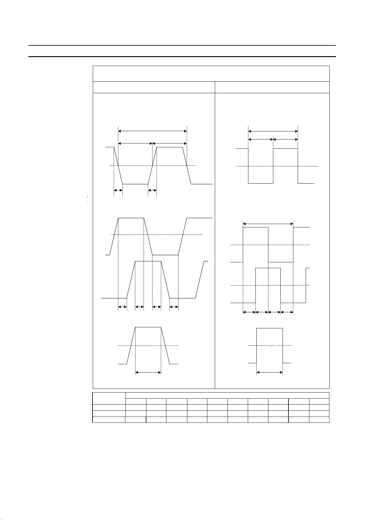
Counter Inputs A, B, Z and Digital Inputs
5/12/24V input signals RS-422 Line Driver signals
Counter inputs A and B
Input pulses with a duty factor of 50%
C
BB
On
Counter Inputs A, B and Z
50%
Off
ts A and B
uty factor of 50%
Relationship between A and B phases with phase
Phase A
B
On
50%
Off
Phase B
phases with phase
uts
On
50%
Off
Z
* Maximum allowed frequency of Z-pulses is 1 kHz * Maxim um allowed frequency of Z-pulses is 1 kHz
differential inputs
DDDD
Counter Input Z * / Digital Inputs (24V)
RS-422 Line Driver signalssignals
AA
On
0V
Off
Relationship between A and B phases with phase
On
0V
Off
Phase A
On
E
0V
Off
Counter inputs A and B
Input pulses with a duty factor of 50%
F
GG
differential inputs
H
On
0V
Off
Relationship between A and B phases with phase
On
0V
Off
Phase A
On
0V
Off
Phase B
Counter inputs A and B
Input pulses with a duty factor of 50%
F
GG
differential inputs
H
II
Counter Input Z *
On
0V
Off
Z
I
I
J
$%
Filter
Selection
10 kHz
50 kHz
500 kHz
<3
>50<3
>10<3
>2
>100
>20
>4
Timing requirement [µs]
>1
>10>4.5
>10
>20
>2
>50>100>10>23
>10
>1
>100
>20
>4
>23
>4.5
JIHGFEDCBA
>10
>10
>10>1
Note As a general guideline it can be stated that if you want the timing requirements for
the Counter Inputs to satisfy the above mentioned specifications, you must pay
attention to the type of output driver of the encoder being used, the length of the
encoder cable and the frequency of the count pulses generated. For example, if
you use an E6B2-type Open Collector encoder (e.g. E6B2-CWZ6C) at 24 V with
10 m cable, you can typically generate count pulses up to 20 kHz. Therefore, if you
Page 28
34#$(1($%'()*+-%*.-05%"%$'#"(+'($+ Section 1-3
want to generate count pulses with higher frequencies, you should use a different
type of encoder (e.g. E6B2-CWZ1X with Line Driver output or a fast push-pull 24
V encoder, e.g. E6C2-CWZ5GH) or reduce the length of the encoder cable.
1-3-4 Output Specifications
Item Specification
Driver Type Open Collector (NPN/PNP selectable)
Operating Voltage Range 12-24V (10.2 to 26.4V)
Maximum Switching Capacity 46 mA at 10.2V to 100 mA at 26.4V (400 mA maximum/common)
(see picture below)
Minimum Switching Current 5 mA
Output ON-delay 100 µs max.
Output OFF-delay 100 µs max.
Leakage Current 0.1 mA max.
Residual Voltage 1.5 V max.
Short Circuit Protection No
Maximum Switching
Capacity
Note 1. Every Digital Output has 2 Output drivers available: NPN and PNP (available
as separate pins on the front connectors). Every Output can be separately (DM-)
configured for NPN or PNP. By default the Outputs are configured as NPN-output
(refer to 3-5-4 "Output Control Configuration").
2. The Digital Outputs are insulated from the I/O-bus but not from each other.
They are not short circuit protected.
3. The Output current must not exceed 400 mA per common (i.e. per 4 Digital Outputs) otherwise the unit will be damaged.
4. The Outputs can be automatically or manually controlled (DM-setting) by using
Force ON/OFF bits in CIO (refer to 3-5 "Output Control").
5. The state control of the 32 Outputs, in case the operating mode of the PLCCPU is changed from RUN/MONITOR → PROGRAM, an I/O Bus error or an
Overflow/Underflow error occurs, can be configured (refer to 3-5-4 "Output
Control Configuration").
The maximum switching current depends upon the power supply voltage, as
shown below.
100
Maximum Switchign Capacity (mA)
46
10.2 20.4 26.4
External Supply Voltage (VDC)
$&
Page 29
6&($7-3'%"'-84-9#1#"#*$#-:&(.# Section 1-4
Power Supply
Characteristics
The power supplied to the Unit, to feed the Digital Outputs, has to be supplied
externally and should be a double insulated class II (over-voltage) type with ratings from 12 to 24 VDC (10.2 to 26.4 VDC). Characteristics of the Power Supply
Input circuitry are summarized in the following table.
Item Specification
Operating Voltage Range 10.2-26.4 VDC
Current Consumption 30 mA max. (load current excluded)
Internal Fault Protection Two 1A (not replaceable) internal fuses in Power Supply lines
Reverse Polarity Protection Yes
1-4 Quick Start Up Reference Guide
Operation and
Configuration
Every Counter of the High-speed Counter Unit can be configured as Simple, Circular or Linear Counter (refer to the next section 1-5 "Operating Procedure Guide-
lines" for quick start up information).
Counters configured as Circular/Linear Counter can use all the functions and features that the Unit offers to you, while Counters configured as Simple Counter only
offer you a limited subset instead. The diagram below shows you all the functional
blocks that the Unit has available to you to operate and configure the Unit (refer to
"Operation and Configuration"). The numbers in grey refer to the table on page 16
to indicate which functions are supported for Simple Counters and which functions
for Circular/Linear Counters.
Capture
2, 3 2, 3
Register
Counter Inputs
1
(A, B, Z)
Simple
Counter*
1, 2, 3, 4
Counter
Start/Stop
9
Measurement
Circular
Linear
Rate
I0
Digital Inputs
3
(I0, I1, I2, I3)
11
Noise Filter
Time-Window
* Diagram is valid for every Counter 1, 2, 3 and 4
I1
I2
I3
2, 3 2, 3, 7
Preset
Register
Counter
Reset
8
Output State
5
Automatic
4
Output Control
4
Output Control
10
Rate History
Log File
Programmable
Output Pulse
Control
Manual
Hysteresis
NPN/PNP
Digital Outputs
6
(O0, O1, O2, O3)
$'
Page 30
6&($7-3'%"'-84-9#1#"#*$#-:&(.# Section 1-4
Exchanging data with CPU The diagram below shows you all the functional blocks that the Unit has available
to you to exchange data with the CS1-CPU (refer to "Exchanging Data with
CPU").
CS1-CPU
13
13
14
15
IOWR
IORD
Interrupts
Interrupts
CS1W-CT021/
CT041
Unit Output Pattern
O3
O2
O1
O0
I0
I1
I2
I3
$(
Page 31

6&($7-3'%"'-84-9#1#"#*$#-:&(.# Section 1-4
Simple Counter Circular / Linear Counter Reference
section
1 Input Signal Types 3-3
• Phase Differential (x1) (=default) • Phase Differential (x1, x2, x4) 3-3-1
• Up & Down 3-3-2
• Pulse & Direction 3-3-3
2 Counter Control using CIO- software bits 3-4
• Open Gate / Start Counter
• Close Gate / Stop Counter
• Preset Counter
• Reset Counter
• Capture Counter Value
3 Digital Input Functions 3-4
• No Function (=default) • No Function
• Open Gate / Start Counter
• Close Gate / Stop Counter
• Preset Counter
• Reset Counter
• Capture Counter Value
• Gate Positive
• Gate Negative
• Preset Rising Edge
• Preset Falling Edge
• Reset Rising Edge
• Reset Falling Edge
• Capture Rising Edge
• Capture Falling Edge
• Stop, Capture and Continue
• Stop, Capture and Continue (inverted)
• Stop, Capture, Reset and Continue
• Stop, Capture, Reset and Continue
(inverted)
• Capture-Reset Rising Edge
• Capture-Reset Falling Edge
• Enable Reset
• Disable Reset
3-4
3-4
4 Output Control 3-5
• Automatic Output Control in:
! Range Mode 3-5-1
! Comparison Mode 3-5-2
• Manual Output Control • Manual Output Control 3-5-3
5 Output State Control 3-5-4
• No (=default) • Yes 3-5-4
6 Output Driver Configuration 3-5-4
• NPN (=default) • NPN
• PNP
3-5-4
$)
Page 32

6&($7-3'%"'-84-9#1#"#*$#-:&(.# Section 1-4
Simple Counter Circular / Linear Counter Reference
section
7 Reset Signals 3-6
• Software Reset Bit • Software Reset Bit
3-6
• Digital Input
• Z-signal
8 Programmable Output Pulses 3-7-1
• No
(=default) • Yes 3-7-1
9 Rate Measurement 3-7-2
• No (=default) • Yes 3-7-2
10 Hysteresis 3-7-3
• No (=default) • Yes 3-7-3
11 Noise Filtering Digital Inputs and Counter Inputs 3-7-4
3-7-4
• 50 kHz (=default)
• 10 kHz
• 50 kHz
• 500 kHz *
1
12 Initial Counter Value 3-7-5
• No (=default) • Yes 3-7-5
13 Supported IORD / IOWR-instructions to read / write 4-5
• DM-data 4-5-1
• Range- and Comparison Data 4-5-2
• Captured Counter Value • Captured Counter Value 4-5-3-1
• Rate History Log File data 4-5-3-2
• Counter Value • Counter Value 4-5-3-3
• (Re) Configure Unit 4-5-3-4
• Error Clear • Error Clear 4-5-3-5
14 Interrupts of Outputs 4-6-1
2
• No*
(=default) • Yes 4-6-1
15 Interrupts of Digital Inputs 4-6-2
3
• No*
(=default) • Yes 4-6-2
*1The 500 kHz filter can only be configured for the Counter Inputs (not for the Dig-
ital Inputs).
2
If in a mixed configuration of Simple/Circular/Linear Counters one or more of
*
the Digital Outputs have been configured to have Interrupt functionality, then
this functionality is applied to the Outputs, both if they are controlled manually
as well as automatically.
3
If in a mixed configuration of Simple/Circular/Linear Counters one or more of
*
the Digital Inputs have been configured to have Interrupt functionality, then this
functionality is applied to the Inputs on a rising or falling edge depending on the
Digital Input Function for which the Digital Inputs have been configured.
$*
Page 33

6&($7-3'%"'-84-9#1#"#*$#-:&(.# Section 1-4
1-4-1 Configuring the High-speed Counter Unit
Configuration Configuring every Counter starts with choosing the Counter Type (Simple, Circu-
lar or Linear).
Simple Counter For Simple Counters you do not have to make any DM-configuration settings,
since for Simple Counters all default (DM-) settings are used. You can choose to
use Simple Counters if you intend to use the Counter only with basic counting
functionality (refer to 3-2-1 "Simple Counter" for details and to 1-5 “Operating Pro-
cedure Guidelines” for a quick start up procedure)
Circular/Linear Counter If you want to use the full available functionality for a Counter, you must configure
it for Circular or Linear Counter (refer to 3-2-2 "Circular Counter" and 3-2-3 "Linear
Counter" for details and to 1-5 "Operating Procedure Guidelines" for a quick start
up procedure).
Next the Input Signal Type (Phase Differential, Up/Down, or Pulse & Direction) for
every Counter has to be defined. Depending on the requirements of the application
one or more (maximum 4) Digital Inputs can be assigned to a Counter. To configure
the Digital Input(s) a choice can be made out of 17 available modes (e.g. Gate,
Enable Reset or Combination Modes, see 3-4 "Digital Input Functions"). During
operation of the Counter, the Counter can be Started, Stopped, Reset, Captured
or Preset by using the Digital Input(s) or the corresponding bits in CIO.
Indirect Addressing for
Circular and Linear
Counters
Controlling the Outputs is done by choosing the Output Control Mode (Range or
Comparison Mode). Furthermore 4 additional control mechanisms are available to
control the Outputs (Programmable Output Pulse, Output State Control, Manual
Control and Hysteresis). Refer to 3-5 "Output Control".
In case the Counter Input Signals (A, B, Z) and the Digital Input Signals (I0 to I3)
are exposed to electromagnetic noise, a noise filter can be configured (10 kHz, 50
kHz (=default) or 500 kHz) to suppress this noise. The 500 kHz noise filter is only
available for the Counter Input Signals and not for the Digital Input Signals. Refer
to 3-7-4 "Noise Filtering".
As background calculation, executed in parallel to operating the Counters, Rate
Measurement can be configured by choosing the appropriate Time-Window [1 to
9999 ms]. The calculated Rate Values are stored in the corresponding Rate History Log File inside the Unit and can be retrieved by issuing an IORD-command
from the PLC Ladder Program. Rate Measurement can be enabled/disabled for
every Counter. Refer to 3-7-2 "Rate Measurement".
The CS1W-CT021/CT041 High-speed Counter Unit is allocated 400 DM-words in
the Special I/O Unit DM-Area and a block of 40 CIO-words in the Special I/O Unit
Area of the PLC. The configuration of the Unit is done by making the appropriate
DM-settings in the Special I/O Unit DM-Area that is allocated to the Unit.
$+
CS1W-CT021:
For the CT021 the Special I/O Unit DM-Area is divided in an area of 30 words to
make the General Unit Settings and 2 blocks of 45 DM-words each to make the
Counter Specific Settings, which are unique for every Counter. The remaining 287
Page 34

6&($7-3'%"'-84-9#1#"#*$#-:&(.# Section 1-4
words of the 400 DM-words can be used as work-words in the PLC Ladder Program.
CS1W-CT041:
For the CT041 the Special I/O Unit DM-Area is divided in an area of 30 words to
make the General Unit Settings and 4 blocks of 45 DM-words each used to make
the Counter Specific Settings, which are unique for every Counter. The remaining
197 words of the 400 DM-words can be used as work-words in the PLC Ladder
Program.
Depending on the Output Control Mode, for every Counter Range- or Comparison
Data can be set. Like this, for every Counter, up to a maximum of 32 Ranges or
Comparison Values can be assigned. You can set the Range- or Comparison Data
in a part of DM or EM which is not being used. If you only intend to use a limited
number of Ranges or Comparison Values then it is also possible to use the workwords of the Special I/O Unit DM-Area to store the Range- or Comparison Data
(197 work-words for the CT041 and 287 work-words for the CT021 are available).
Therefore, at the end of every block with Counter Specific Settings, you can specify an Indirect Address. This Indirect Address points to the actual memory location
where the Range- or Comparison Settings of that specific Counter are stored.
For a detailed description about the CIO- and DM-Memory Allocation refer to 4-2
"Memory Allocation".
Note During operation of the Unit, for Circular and Linear Counters run-time configura-
tion is possible by using the IOWR-instruction from the PLC Ladder Program (refer
to 4-5 "Supported IOWR/IORD-Instructions"). Additionally, the Digital Inputs and
Outputs can be configured to generate interrupts to the PLC by setting the appropriate Interrupt Masks in DM. (refer to 4-6 "Interrupts")
$,
Page 35

;4#"%'(*2-!")$#.&"#-:&(.#<(*#+ Section 1-5
1-5 Operating Procedure Guidelines
The DIP switch at the back of the Unit can be used to operate every Counter as
Simple Counter or as Circular/Linear Counter. Setting the DIP switch in the appropriate position defines the Counter Type.
The Operation Procedure Guidelines consists of 5 steps. In step 1 of the
Operating Procedure Guidelines for every Counter the Type has to be set with
the DIP switch into one of the following configurations:
Configuration 1 All Counters as Simple Counter
Configuration 2 All Counters as Circular/Linear Counter
Configuration 3 Mixed configuration of Simple/Circular/Linear Counters
Next you must execute step 2, 3, 4, and 5. Once the I/O table is created in step 5,
the Unit must be configured if you have chosen for Configuration 2 or 3. If you have
chosen for Configuration 1 the Unit is ready to operate. Consequently guidelines
to be followed after step 5 will depend on the Configuration made in step 1.
Setting Counter Type
1, 2, 3… 1. Set the Counter Type for every Counter at the back of the Unit. Refer to 2-1-3
"Counter Type Switch" for further details.
Counter Type Switch:
OFF = Simple Counter
ON = Circular/Linear Counter
2. Set the Machine Number. Refer to 2-1-4 "Machine Number Switch" for further
details.
Machine Number Switch:
MACH
No.
Set between 00 - 92
%-
Page 36

;4#"%'(*2-!")$#.&"#-:&(.#<(*#+ Section 1-5
3. Install and wire the Unit. Refer to 2-2 "Installation" and 2-3 "Wiring" for further
details.
4. Turn ON the Power to the PLC.
Power ON
5. Create the I/O table. The I/O table can be created by using CX-Programmer
Support Software or a Programming Console.
CX-Programmer
Programming Console
Unit Configuration After the I/O table is created in step 5, you have to configure the Unit if you have
chosen for Configuration 2 or 3 in step 1. Configuration is done by making the
appropriate DM-settings. The Unit can be configured by using CX-Programmer
Support Software or a Programming Console. Two Programming Consoles can be
used with the CS1-series CPU Units: the C200H-PRO27-E and the CQM1PRO01-E. CS1W-KS001 Key Sheet must be used for both.
Depending on the Configuration (1, 2 or 3) that you specified in step 1, you should
continue with the corresponding step of the configuration-process:
%$
Page 37

;4#"%'(*2-!")$#.&"#-:&(.#<(*#+ Section 1-5
Configuration 1 All Counters as Simple Counters:
1, 2, 3… 1. No (DM-) configuration settings can be made. The Unit is ready to count and
will use all default DM-values. All data related to the Simple Counter is now
being exchanged between the PLC and the Unit in CIO-memory and available
for usage in the PLC Ladder Program.
2. Create and RUN a Ladder Program in the PLC. Refer to section 4 "Exchanging
Data with CPU" for details on the interface between the High-speed Counter
Unit and the CPU. Section 6-1 “Flow Control” describes an application example
using the Simple Counter.
Refer to 3-2-1 "Simple Counter" for more details about the Simple Counter.
Configuration 2 All Counters as Circular or Linear Counter:
1, 2, 3… 1. Every Counter can now be separately (DM-) configured. For this purpose you
can use a Programming Console or CX-Programmer Support Software. The
configuration of the Counter Type (Linear or Circular Counter) is done by DMsetting. Refer to section 3 "Operation and Configuration" for detailed information about configuring the Unit.
2. Power up the PLC again or turn the Special I/O Unit Restart Bit to ON and then
OFF again (to transfer the DM-settings). All data related to Circular /Linear
Counters is now being exchanged between the PLC and the Unit in CIO-memory and available for usage in the Ladder Program.
3. Create and RUN a Ladder Program in the PLC. Refer to section 4 "Exchanging
Data with CPU" for details on the interface between the CS1W-High-speed
Counter Unit and the CPU. Refer to sections 6-2 to 6-5 for application examples
using Circular and Linear Counters.
Refer to 3-2-2 "Circular Counter" and 3-2-3 "Linear Counter" for more details
about both Counter Types. Refer to 4-1-2 "Special I/O Units Restart bits" for more
information about restarting the Unit.
Configuration 3 Mixed Configuration Simple/Circular/Linear Counters:
1, 2, 3… 1. Every Counter that has been set to Circular/Linear Counter can now be (DM-)
configured. For this purpose you can use a Programming Console or CX-Programmer Support Software. The configuration of the Counter Type (Linear or
Circular Counter) is done by DM-setting. Refer to section 3 "Operation and
Configuration" for detailed information about configuring the Unit. For the
Counters that have been configured for Simple Counter no (DM-) configuration
has to be done since the default (=0000) DM-settings are used for these
Counters.
2. Power up the PLC again or turn the Special I/O Unit Restart Bit to ON and then
OFF again (to transfer the DM-settings). All data related to Circular/Linear
Counters is now being exchanged between the PLC and the Unit in CIO-memory and available for usage in the PLC Ladder Program.
3. Create and RUN a Ladder Program in the PLC. Refer to section 4 "Exchanging
Data with CPU" for details on the interface between the High-speed Counter
Unit and the CPU. Refer to sections 6-2 to 6-5 for application examples using
Circular and Linear Counters.
Refer to 3-2-1 "Simple Counter", 3-2-2 "Circular Counter" and 3-2-3 "Linear Coun-
ter" for more details about the Counter Types. Refer to 4-1-2 "Special I/O Units
Restart bits" for more information about restarting the Unit.
%%
Page 38

=44<($%'()*-="#%+ Section 1-6
Note For using Simple Counters you do not have to clear the corresponding DM-set-
tings to zero (=0000), since the Unit does not use this information and always uses
the default (=0000) settings.
1-6 Application Areas
The main application areas of the High-speed Counter Unit is where signals with
high frequencies are counted and high-speed responses have to be triggered at
predefined Counter Values. Application areas include:
• Packaging and Sorting plants
• Dosing or proportioning plants
• Process Industry
Typical applications in which the CS1W-CT021/CT041 can be used:
• (CAM)-Positioning (refer to 6-3 "Positioning" and 6-4 "CAM-positioning")
• Position Monitoring
• Length Measurement (refer to 6-2 "Length Measurement")
• Speed Control (refer to 6-5 "Speed Control")
• Flow Control (refer to 6-1 "Flow Control")
• Energy Measurement
Section 6 "Application Examples" describes typical application examples in which
the High-speed Counter can be used, including sample ladder programs.
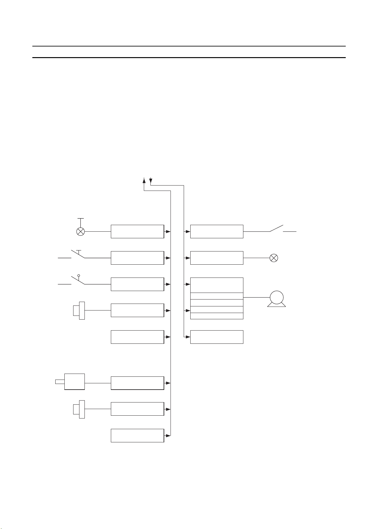
Section 6-2 "Length Measurement", for example, describes the following application:
Photo-electric
sensor (D2)
Pusher
Conveyer beld 2 Conveyer beld 1
Encoder (E2)
Motor 2
Photo-electric
sensor (D1)
Encoder (E1)
CH1
CH2
CH3
CH4
MACH
No.
CT041
RUN
A
A
A
A
20
AB AB
ERC
B
Z
I0
B
Z
I1
B
Z
I2
B
Z
I3
1
X10
ERH
O0
O1
O2
O3
0
X10
1201
CN1CN2
Motor 1
PS204S
Power
%&
Page 39

Page 40

SECTION 2
Components, Installation and Wiring
This section provides details of the components, switch settings and other information required to install and operate
CS1W-CT021/CT041 High-speed Counter Units.
2-1 Components and Switch Settings............................................................................................................................ 26
2-1-1 Components ............................................................................................................................................... 26
2-1-2 Indicators ................................................................................................................................................... 27
2-1-3 Counter Type Switch ................................................................................................................................. 28
2-1-4 Machine Number Switch ........................................................................................................................... 29
2-2 Installation............................................................................................................................................................... 30
2-3 Wiring...................................................................................................................................................................... 32
2-3-1 Connector Pin-layout ................................................................................................................................. 32
2-3-2 Connector Wiring Methods ....................................................................................................................... 33
2-3-3 Important Wiring Considerations .............................................................................................................. 36
2-3-4 Internal Circuitry ....................................................................................................................................... 37
2-3-5 Digital I/O Circuit Configurations............................................................................................................. 39
2-3-6 Counter Input Configurations.................................................................................................................... 41
%(
Page 41

0)>4)*#*'+-%*.-3?('$5-3#''(*2+ Section 2-1
2-1 Components and Switch Settings
2-1-1 Components
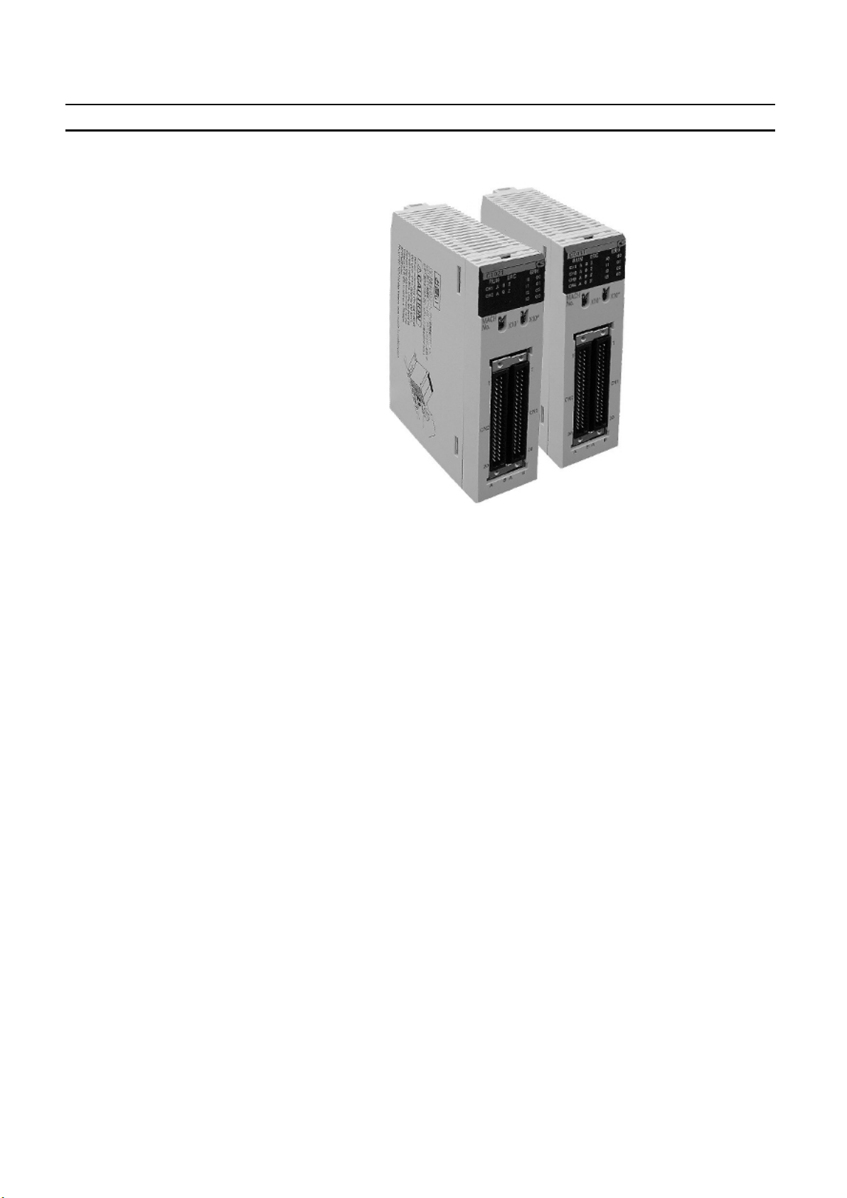
Front and Rear View
Indicators
Machine
Number Switch
CT021
RUN
CH1
CH2
MACH
NO
AABBZ
ERC
ZI0I1
X10
ERH
I2
I3
1
X10
CT041
RUN
ERC
ERH
I0
O0
CH1
A
B
CH2
A
CH3
CH4
MACH
No.
B
A
B
A
B
O1
O2
O3
0
O0
Z
Z
I1
O1
Z
I2
O2
Z
I3
X10
O3
1
0
X10
Counter Mode
Switch
Side View
1
20
A B A B
35 mm
1
1
1
130 mm
CN1CN2
CN1CN2
Bus
Connector
20
20
A B A B
35 mm
20
35 mm
Hook
%)
130 mm
Bus
Connector
100 mm
Page 42

0)>4)*#*'+-%*.-3?('$5-3#''(*2+ Section 2-1
2-1-2 Indicators
The indicators on the LED-display show the operating status of the Unit. The following table shows the meaning of the indicators.
LED Colour State Description
RUN Green ON Unit is in operation (i.e. Unit has initialised
normally after (re-) starting the Unit).
OFF Unit is not in operation (i.e. Unit was not able
to initialise normally after (re-) starting the
Unit or the power to the Unit is switched OFF).
ERC Red ON Unit has operational failure due to a detected
error. (For a list of all the errors that can cause
an operational failure, see 5-2 "Error codes"”.)
OFF Unit has no operational failure.
ERH Red ON CPU Unit has operational failure. (For a list of
all the errors that can occur at the CPU Unit
see 5-1 "Error Indicators")
OFF CPU Unit has no operational failure.
CH1/2/3/4 Green ON Channel 1/2/3/4 (i.e. Counter 1/2/3/4) is ready
to count (the corresponding counting gate is
open).
OFF Counter 1/2/3/4 is not ready to count (the
corresponding counting gate is closed).
A/B/ Z Yellow ON Physical Input A/B/Z has turned ON.
(Every Counter is characterised by the signals
A/B/Z.)
OFF Physical Input A/B/Z is turned OFF.
I0/I1/I2/I3 Yellow ON Digital Input (I0/I1/I2/I3) is turned ON.
OFF Digital Input (I0/I1/I2/I3) is turned OFF.
O0/O1/O2/
O3
Yellow ON Digital Output (O0/O1/O2/O3) is turned ON.
OFF Digital Output (O0/O1/O2/O3) is turned OFF.
%*
Page 43

0)>4)*#*'+-%*.-3?('$5-3#''(*2+ Section 2-1
2-1-3 Counter Type Switch
The Counter Type Switch, at the back of the Unit, is used to set the Counter Type
for every individual Counter separately. By default all Counters are set to Simple
Counter.
ON Position
OFF Position
The following table shows how the Counters can be configured:
Pin Counter Position Type
1 #1 ON Circular/Linear Counter
OFF Simple Counter
2 #2 ON Circular/Linear Counter
OFF Simple Counter
3* #3 ON Circular/Linear Counter
OFF Simple Counter
4* #4 ON Circular/Linear Counter
OFF Simple Counter
* CS1W-CT041 High-speed Counter Unit only.
After having set the DIP switch of the Counter to ON, further selection between
Circular and Linear Counter, is done by DM-setting. Counters that are configured
for Circular/Linear Counter can make use of all the features that the High-speed
Counter Unit offers. More information on Circular and Linear Counters can be
found in 3-2-2 "Circular Counter" and 3-2-3 "Linear Counter" respectively.
The Simple Counter is an extra feature of the High-speed Counter Unit, that enables an easy and fast set-up of the Unit since no (DM-) configuration settings have
to be made (all default (=0000) DM-settings are used). Consequently for Simple
Counters only a reduced subset of all the features that the Unit offers are available. For further details about the Simple Counter and the features supported, see
3-2-1 "Simple Counter".
!Caution Since the Counter Type Switch is located at the back of the Unit, always turn OFF
the power to the PLC before installing or removing the Unit.
%+
Page 44

0)>4)*#*'+-%*.-3?('$5-3#''(*2+ Section 2-1
2-1-4 Machine Number Switch
The CPU Unit and the High-speed Counter Unit exchange data via the Special
I/O Unit Area (CIO) and the Special I/O Unit DM Area. The High-speed Counter
Unit is allocated the words for 4 Units. This means that 40 words in the Special
I/O Unit Area (CIO) and 400 words in the Special I/O Unit DM Area are allocated.
The allocation of these words is done according to the Machine Number set. The
Machine Number is set by using the two Machine Number rotary switches on the
front panel of the Unit.
Always turn OFF the power before setting the Machine Number. Use a flat-blade
screwdriver, being careful not to damage the switch. Be sure not to leave the
switch midway between settings.
Note The Machine Number determines which words in the CPU Unit’s Special I/O Unit
Area (CIO 2000 to CIO 2959 and DM 20000 to DM 29599) are allocated to the
High-speed Counter Unit. Since the Unit is allocated 400 DM-words and 40 CIOwords, the Machine Number can only be set between 00 and 92. The Machine
Numbers 93, 94 and 95 can not be set.
Switch
Setting
0 #0 CIO 2000 to CIO 2039 D20000 to D20399
1 #1 CIO 2010 to CIO 2049 D20100 to D20499
2 #2 CIO 2020 to CIO 2059 D20200 to D20599
3 #3 CIO 2030 to CIO 2069 D20300 to D20699
4 #4 CIO 2040 to CIO 2079 D20400 to D20799
5 #5 CIO 2050 to CIO 2089 D20500 to D20899
6 #6 CIO 2060 to CIO 2099 D20600 to D20999
7 #7 CIO 2070 to CIO 2109 D20700 to D21009
8 #8 CIO 2080 to CIO 2119 D20800 to D21199
9 #9 CIO 2090 to CIO 2129 D20900 to D21299
10 #10 CIO 2100 to CIO 2139 D21000 to D21399
…… … …
n #n CIO 2000 + (n * 10) to
…… … …
92 #92 CIO 2920 to CIO 2959 D29200 to D 29599
93 Cannot be
94 Cannot be
95 Cannot be
Machine
Number
set
set
set
I/O Refresh Data Area
Addresses
CIO 2000 + (n * 10) + 39
Not Applicable Not Applicable
Not Applicable Not Applicable
Not Applicable Not Applicable
Special I/O Unit DM
Area Addresses
D 20000 + (n * 100) to
D 20000 + (n * 100) + 399
%,
Page 45

@*+'%<<%'()* Section 2-2
Note 1. If two or more Special I/O Units are assigned the same Machine Number, a fatal
error “Unit No. Duplication Error” (in the PLC-CPU) will be generated (A40113
will turn ON) and the PLC will not operate.
2. The High-speed Counter Unit is allocated the words for 4 Units. If you use Special I/O Units that are allocated more than 100 DM-words and 10 CIO-words,
like the CS1W-CT021/CT041 High-speed Counter Unit, you should make sure
that no memory overlapping occurs. If the Machine Number for the High-speed
Counter Unit is set to ‘n’ the Machine Number of the consecutive Special I/O
Unit should be set to ‘n+4’, in order to avoid memory overlapping. In case two
or more Special I/O Units have set Machine Numbers that cause an overlapping of allocated memory a fatal error “Unit No. Duplication Error” (in the PLCCPU) will be generated (A40113 will turn ON) and the PLC will not operate.
3. Besides the memory that is allocated to the High-speed Counter Unit in the
Special I/O Unit DM Area, for every Counter additional memory can be allocated in DM/EM. This extra allocated amount of memory is used to make the
Counter Specific Settings related to Range or Comparison Mode. Memory is
allocated by specifying an Indirect Address for every Counter in the Special I/
O Unit DM Area. For details about Indirect Addressing refer to 4-2-2 "Indirect
Addressing".
2-2 Installation
!Caution Leave the protective label on top of the Unit as long as the Unit is not mounted
!Caution Be sure to turn OFF the power supply to the PLC before installing or removing
Note Before you start mounting the Unit to the backplane, make sure that the Counter
1, 2, 3… 1. Hook the top of the High-speed Counter Unit into the slot on the Backplane and
and wired completely, in order to prevent wire clippings or other materials from
getting inside the Unit. When the mounting and wiring has been completed, the
label must be removed to allow air circulation and heat radiation.
Units or connecting or disconnecting connectors.
Type switch, at the back of the Unit, is set in the appropriate position.
Use the following procedure to mount CS1W-CT021/CT041 High-speed Counter
Units to the backplane.
rotate the Unit downwards as shown in the following figure.
Hook
Backplane
&-
Page 46

@*+'%<<%'()* Section 2-2
2. While making sure to align the Unit properly with the (bus-) connectors, tighten
the mounting screws securely using a flat-blade screwdriver with a maximum
tightening torque of 0.4 Nm.
Mounting screw
Note To remove the Unit, first loosen the mounting screws.
Leave enough space below each Rack, as shown in the following diagram to be
able to mount or remove Units in a later stage.
Flat-blade screwdriver
20 mm min.
Backplane
20 mm min.
&$
Page 47

A("(*2 Section 2-3
2-3 Wiring
2-3-1 Connector Pin-layout
The two 40-pins connectors (CN1 and CN2) on the front of the Unit are both
divided in Row A and Row B, each row containing 20-pins as indicated on front of
the Unit. The Digital Outputs, Digital Inputs and the Counter Inputs of the Unit are
logically grouped together and allocated to the pins of connector 1 and 2. The following table lists the allocation of the external signals to the respective pins.
Item Connector 2 (CN2) Pin
Row A Row B Row A Row B
Power Supply (to
feed the outputs)
Digital Outputs
[0-3] (NPN/PNP)
Spare 4 4
Digital Inputs
[0-3]
Spare 7 7
Counter 1 &
Counter 2
Spare 14 14
-PS: 0V +PS: 12 to 24V 1 -PS: 0V +PS:12 to 24V 1
O2: NPN O2: PNP 2 O0: NPN O0: PNP 2
O3: NPN O3: PNP 3 O1: NPN O1: PNP 3
I2: 0V I2: 24V 5 I0: 0V I0: 24V 5
I3: 0V I3: 24V 6 I1: 0V I1: 24V 6
A
CH2: LD- / 0V CH2: LD+ 8 CH1: LD- / 0V CH1: LD+ 8
CH2: 12V CH2: 24V 9 CH1: 5V CH1: 24V 9
B
CH2: LD- / 0V CH2: LD+ 10 CH1: LD- / 0V CH1: LD+ 10
CH2: 12V CH2: 24V 11 CH1: 5V CH1: 24V 11
Z
CH2: LD- / 0V CH2: LD+ 12 CH1: LD- / 0V CH1: LD+ 12
CH2: 12V CH2: 24V 13 CH1: 5V CH1: 24V 13
No.
Connector 1 (CN1) Pin
No.
Counter 3 &
Counter 4*
Power Supply External power has to be applied to the Power Supply pins in order to feed the Dig-
A
CH4: LD- / 0V CH4: LD+ 15 CH3: LD- / 0V CH3: LD+ 15
CH4: 12V CH4: 24V 16 CH3: 5V CH3: 24V 16
B
CH4: LD- / 0V CH4: LD+ 17 CH3: LD- / 0V CH3: LD+ 17
CH4:12V CH4: 24V 18 CH3: 5V CH3: 24V 18
Z
CH4: LD- / 0V CH4: LD+ 19 CH3: LD- / 0V CH3: LD+ 19
CH4:12V CH4: 24V 20 CH3: 5V CH3: 24V 20
* CS1W-CT041 High-speed Counter Unit only.
ital Outputs. Depending on what your application requires you can apply an external voltage between 12 to 24VDC. The Power Supply lines (+PS) of CN1 and CN2
are internally connected, as are the 0V lines (-PS). In this way the power only has
to be applied to one pair of +PS/-PS lines on CN1 or CN2. In case the Digital Outputs are not used in your application, no external power has to be supplied.
&%
Page 48

A("(*2 Section 2-3
Digital Outputs Every single Digital Output (O0, O1, O2 and O3) can be used in a NPN- or PNP-
configuration depending on your application needs. This configuration is done by
making the corresponding DM-setting (refer to 3-5-4 "Output Control Configura-
tion" for more details). After you have configured the Digital Outputs for NPN or PNP
you should make sure to use the corresponding physical NPN or PNP output pin.
Digital Inputs The Digital Inputs should be supplied with 24 VDC signals. Every Digital Input (I0,
I1, I2 and I3) is equipped with a separate Ground Signal (0V) and has its own electronic input circuitry. This gives you the opportunity to connect sensors either with
a NPN- or PNP-output driver. By making the appropriate DM-setting it is possible
to assign multiple Digital Inputs to single Counters (refer to 3-4 "Digital Input Func-
tions" for more details).
Counter Inputs To the Counter Inputs of the High-speed Counter Unit signals can be applied orig-
inating from one of the following driver types:
• RS-422 Line Driver
• 5, 12 and 24VDC signals from NPN- or PNP Drivers
The Unit allows you to connect Line Driver signals and 24VDC signals to any
Counter. To the CS1W-CT021, 5VDC and 12VDC signals can be applied only to
Counters 1 and 2 respectively. The CS1W-CT041 allows connecting 5VDC and
12VDC signals only to Counter 1 and 3 and Counter 2 and 4 respectively. The following table gives an overview of which driver signals can be applied to which
Counters:
Counter 1
Counter 2
Counter 3*
Counter 4*
* CS1W-CT041 High-speed Counter Unit only.
2-3-2 Connector Wiring Methods
!Caution Do not remove the label on top of the High-speed Counter Unit until the wiring
has finished. Not doing could cause wire cuttings and other materials falling into
the Unit or short circuit the internal circuitry, resulting in malfunctioning or burning. Be sure to remove the label after wiring the connectors to allow air circulation
and heat radiation.
!Caution Be sure that all the connectors are wired correctly and properly connected to the
High-speed Counter Unit, to prevent the Unit from malfunctioning.
To wire the CS1W-CT021/CT041 in order to connect the external signals (Power
Supply, the Digital I/O and the Counter Inputs) two methods are available:
1. Directly connecting the wires and cables to the external connector, which is
standard delivered with the High-speed Counter Unit
Line Driver 5VDC 12VDC 24VDC
• • •
• • •
• • •
• • •
&&
Page 49

A("(*2 Section 2-3
2. Indirectly connecting the wires and cables to the screw terminals of a Terminal
Block Unit. The Terminal Block Unit is connected to the Unit with a standard
(flat-) cable. Both parts can be ordered separately.
External Connector The connector has to be assembled from the separate parts that it exists of and
that are supplied together with the Unit. Most important part is the connector jack
(FCN-361J040) that contains 40 soldering terminals to which the wires have to be
soldered.
Wiring the soldering
terminals
A B
A B
1
5
20
B1
B2
B3
B4
B5
B6
B19
B20
Insulating tube
Wire
(cross section: 0,3 mm
Connector (jack) with soldering terminals
2
max.)
A1
A2
A3
A4
A5
A6
A19
A20
Cable separation
Numbering of the soldering terminals on connector (jack).
For an overview of the connector Pin-layout refer to
Input and/or Output cable
Encoder cable
2-3-1 "Connector Pin-layout".
&'
Page 50

A("(*2 Section 2-3
Assembling Connectors
Three, M2 pan-head screws
(8 mm long)
Case
Connector jack
Case
Three M2 nuts
Two, M2.6 long screws
One M2.6
pan-head screw
(6 mm long)
Cable clamp
One, M2.6 nut
Note 1. The cross section of the signal wires that can be connected to each soldering
terminal must be ≤ 0.3 mm
2
2. Do not short circuit any terminals when soldering. Recommended is to cover
every soldered wire with an insulated tube.
3. When using multi-conductor cables, separate the input- and output cables.
Terminal Block Unit
Besides direct connection as described above, it is also possible to make all the
connections for the external signals to screw-terminals. This is easier and less
time-consuming than soldering the wires to the external connector. For this purpose you should use a Terminal Block Unit. The following Terminal Block Units are
recommended for using together with the CS1W-CT021/CT041 High-speed
Counter Unit:
• XW2B-40G4, which has 40 screw -terminals (M2.4) available
• XW2B-40G5, which has 40 screw -terminals (M3.5) available
These Terminal Block Units can be mounted to a DIN-rail or can be mounted using
screws. The connectors (CN1 and CN2) on front of the Unit should each be connected to a Terminal Block Unit through a standard (40 wire) cable. For this purpose you can use the standard available cables with product-number XW2Z-xxxB.
&(
Page 51

A("(*2 Section 2-3
The length of the cable is indicated by ‘xxx’ in centimetres. The following cables
are available:
• XW2Z-050B (0.5 m)
• XW2Z-100B (1 m)
• XW2Z-150B (1.5 m)
• XW2Z-200B (2 m)
• XW2Z-300B (3 m)
• XW2Z-500B (5 m)
The next figure shows how to use the Terminal Block Unit in a typical configuration
together with the CS1W-CT021/CT041 High-speed Counter:
Refer to Appendix B "Using Terminal Block Units with Screw-terminals" for infor-
mation on the numbering of the screw-terminals. You need this information in case
you want to connect the external signals via Terminal Block Units to the Highspeed Counter Unit.
2-3-3 Important Wiring Considerations
Use the following guidelines when planning the system wiring of the Unit:
• Disconnect the power to the PLC-system before wiring the Unit.
• Make sure the PLC-system is properly grounded.
• Use shielded, twisted pair cables and ground the shield when wiring the Coun-
ter Inputs (A, B, Z) and the Digital Inputs. When grounding the shield at the side
of the Unit, use the same reference as the ground terminal of the PLC-Power
Supply is connected to.
• Make the wiring for the Counter Inputs A, B and Z as short as possible and do
not route the wires parallel to lines that produce a lot of noise, such as high-voltage power lines.
• Try to use a separate stabilised Power Supply for the High-speed Counter Unit
and another Power Supply for other Units.
&)
Page 52

A("(*2 Section 2-3
2-3-4 Internal Circuitry
Digital Input Circuitry
Counter Input Circuitry
Phase A
Phase B
24V
0V
24V
5V/12V
LD+
0V/LD-
24V
5V/12V
LD+
0V/LD-
Digital Input IO:
B5 (24V)
A5 (0V)
Digital Input I1: Digital Input I2: Digital Input I3:
B6 (24V)
B5 (24V)
A6 (0V) A5 (0V)
Connector
CN1
Connector
CN2
B6 (24V)
A6 (0V)
Counter 1: Counter 2: Counter 3: Counter 4:
B9 (24V) B9 (24V) B16 (24V) B16 (24V)
A9 (5V) A9 (12V) A16 (5V) A16 (12V)
B8 (LD+) B8 (LD+) B15 (LD+) B15 (LD+)
A8 (0V/LD-) A8 (0V/LD-) A15 (0V/LD-) A15 (0V/LD-)
Counter 1: Counter 2: Counter 3: Counter 4:
B11 (24V) B11 (24V) B18 (24V) B18 (24V)
A11 (5V) A11 (12V) A18 (5V) A18 (12V)
B10 (LD+) B10 (LD+) B17 (LD+) B17 (LD+)
A10 (0V/LD-) A10 (0V/LD-) A17 0V/LD-) A17 (0V/LD-)
Phase Z
Counter 1: Counter 2: Counter 3: Counter 4:
24V
B13 (24V) B13 (24V) B20 (24V) B20 (24V)
5V/12V
A13 (5V) A13 (12V) A20 (5V) A20 (12V)
LD+
B12 (LD+) B12 (LD+) B19 (LD+) B19 (LD+)
0V/LD-
A12 (0V/LD-) A12 (0V/LD-) A19 0V/LD-) A19 (0V/LD-)
Connector
CN1
Connector
CN2
Connector
CN1
Connector
CN2
&*
Page 53

A("(*2 Section 2-3
Digital Output Circuitry
High-speed Counter
Fuse
B1 (CN1 and CN2):
PS+: 12-24 V DC Power Supply
for Digital Outputs O0 - O3
B2 (CN1): Digital Output O0 (PNP)
B3 (CN1): Digital Output O1 (PNP)
B2 (CN2): Digital Output O2 (PNP)
B3 (CN2): Digital Output O3 (PNP)
A2 (CN1): Digital Output O0 (NPN)
A3 (CN1): Digital Output O1 (NPN)
A2 (CN2): Digital Output O2 (NPN)
Internal Circuitry (galvanically isolated from Digital Output Circuitry
A3 (CN2): Digital Output O3 (NPN)
Fuse
NPN
Digital Output O0
PNP
NPN
Digital Output O1
PNP
NPN
Digital Output O2
PNP
NPN
Digital Output O3
PNP
Software witches for every Digital Output
A1 (CN1 and CN2): PS-: 0V COM
for Digital Outputs O0-O3
&+
The Power Supply feeds the Digital Outputs, for both NPN- as PNP-configuration.
Page 54

A("(*2 Section 2-3
2-3-5 Digital I/O Circuit Configurations
The following examples make clear how to wire the Digital Inputs and the Digital
Outputs.
24 VDC NPN Sensor
24 VDC PNP Sensor
NPN Sensor
PNP Sensor
0V
+ 24 V
Shielded twisted-pair cable
+ 24 V
0V
Shielded twisted-pair cable
24 V DC Power Supply
24 V DC Power Supply
High-speed Counter
B5
A5
Digital Input I0 on Connector CN1
High-speed Counter
B5
A5
Digital Input I0 on Connector CN1
&,
Page 55

A("(*2 Section 2-3
Wiring example NPN/PNP
Digital Output
Internal Circuitry
Fuse (1A)
B1 (CN1 or CN2): PS+
B2 (CN1): O0 (PNP)
B2 (CN2): O2 (PNP)
Load
12 to 24 V DC Power Suply
-12 to 24 V
0V
Load
A3 (CN1): O1 (NPN)
A3 (CN2): O3 (NPN)
Load Load
Fuse (1A)
NPN
Digital Output O0 (PNP)
PNP
NPN
Digital Output O1 (NPN)
PNP
NPN
Digital Output O2 (PNP)
PNP
NPN
Digital Output O3 (NPN)
PNP
Set the software switches for every Digital Output in the appropriate position
A1 (CN1 or CN2): PS-
'-
Page 56

A("(*2 Section 2-3
2-3-6 Counter Input Configurations
The following examples make clear how to wire the Counter Inputs in different configurations according to the output-driver of the encoder or proximity switch that
you want to use. The configurations that are shown here, related to a specific output-driver, can also be referred to in case you want to use other pulse generating
equipment with similar output-drivers.
5/12/24 VDC NPN Open
Collector
Black: Phase A
Encoder
White: Phase B
Orange: Phase Z
High-speed Counter
Terminals (CN1)
B9 (Phase A 24V)
A8 (Phase A 0V)
B11 (Phase B 24V)
A10 (Phase B 0V)
B13 (Phase Z 24V)
A12 (Phase Z 0V)
Power Supply
Ex E6C2-CWZ6C
NPN Open-Collector outputs
0V
+24V
Shielded twisted-pair cable
A
I
I
Phase A
B
I
I
Phase B
Brown: + Vcc
Blue: 0V (COM)
24V DC
Power Supply
24V DC Power Supply
Counter 1
0V
+24V
High-speed Counter
B9
A8
B11
A10
B13
Encoder
Z
I
I
Phase Z
A12
Connector CN1
'$
Page 57

A("(*2 Section 2-3
5/12/24 VDC PNP Open
Collector
Encoder
Black: Phase A
White: Phase B
Orange: Phase Z
High-speed Counter
Terminals (CN2)
B9 (Phase A 24V)
A8 (Phase A 0V)
B11 (Phase B 24V)
A10 (Phase B 0V)
B13 (Phase Z 24V)
A12 (Phase Z 0V)
Power Supply
Ex E6C2-CWZ5B
PNP Open-Collector outputs
+24V
0V
Shielded twisted-pair cable
I
A
Phase A
I
B
Phase B
Brown: + Vcc
Blue: 0V (COM)
0V
+24V
24V DC
Power Supply
24V DC Power Supply
Counter 2
High-speed Counter
B9
A8
B11
A10
B13
'%
Encoder
I
Z
Phase Z
A12
Connector CN1
Page 58

A("(*2 Section 2-3
Line Driver (RS422)
High-speed Counter
Terminals (CN1)
Encoder
Black: Phase A+
Black/red: Phase A-
White: Phase B+
White/red: Phase B-
Orange: Phase Z+
Orange/red: Phase Z-
B15 (Phase A+, LD+)
A15 (Phase A-, LD-)
B17 (Phase B+, LD+)
A17 (Phase B-, LD-)
B19 (Phase Z+, LD+)
A19 (Phase Z-, LD-)
Ex. E6B2-CWZ1X
Line Driver outputs
Power Supply
A+
A-
B+
B-
Z+
Brown: 5V DC
Blue: 0V (COM)
Shielded twisted-pair cable
Counter 3
0V
+5V
5V DC
Power Supply
High-speed Counter
B15
A15
B17
A17
B19
Z-
A19
Connector CN1Encoder
'&
Page 59

A("(*2 Section 2-3
''
Page 60

SECTION 3
Operation and Configuration
This section describes how to configure the CS1-CT021/CT041 High-speed Counter Unit and how to operate the Unit
according to the specific requirements of your application.
3-1 Overview ................................................................................................................................................................. 46
3-2 Counter Types ......................................................................................................................................................... 47
3-2-1 Simple Counter .......................................................................................................................................... 47
3-2-2 Circular Counter ........................................................................................................................................ 52
3-2-3 Linear Counter ........................................................................................................................................... 53
3-3 Input Signal Types................................................................................................................................................... 55
3-3-1 Phase Differential ...................................................................................................................................... 55
3-3-2 Up & Down ............................................................................................................................................... 56
3-3-3 Pulse & Direction ...................................................................................................................................... 57
3-4 Digital Input Functions............................................................................................................................................ 58
3-5 Output Control......................................................................................................................................................... 65
3-5-1 Range Mode............................................................................................................................................... 67
3-5-1-1 Range Mode Overview ............................................................................................................. 69
3-5-1-2 Configuration and operation in Range Mode ........................................................................... 70
3-5-2 Comparison Mode ..................................................................................................................................... 72
3-5-2-1 Comparison Mode Overview.................................................................................................... 74
3-5-2-2 Configuration and operation in Comparison Mode.................................................................. 75
3-5-3 Manual Output Control.............................................................................................................................. 77
3-5-4 Output Control Configuration ................................................................................................................... 78
3-6 Reset Signals ........................................................................................................................................................... 79
3-7 Extra Functions ....................................................................................................................................................... 81
3-7-1 Programmable Output Pulses .................................................................................................................... 81
3-7-2 Rate Measurement ..................................................................................................................................... 83
3-7-3 Hysteresis................................................................................................................................................... 88
3-7-4 Noise Filtering ........................................................................................................................................... 89
3-7-5 Initial Counter Value.................................................................................................................................. 90
'(
Page 61

;B#"B(#? Section 3-1
3-1 Overview
After you have installed and wired the CS1W-CT021/CT041 High-speed Counter
Unit as described in 2-2 "Installation" and 2-3 "Wiring", you have to configure the
Unit by making DM-settings. Only Counters that have been configured for Circular/
Linear Counter (corresponding DIP switch at the back of the Unit in the ON-position) can be DM-configured. For Simple Counters the default DM-settings are
used and no DM-settings can be made.
In this section you will learn how to configure the CS1W-CT021/CT041 Highspeed Counter Unit in order to adjust the behaviour of the Unit according to the
specific requirements of your application (refer to 1-4 "Quick Start Up Reference
Guide" for an overview of the configuration items for every Counter). Also throughout this section, the CIO-words that are relevant to operate the Unit from the PLC
ladder program are mentioned (refer to 4-2-3 "CIO-Memory Mapping" for an over-
view). For an overview of all the DM-settings that can be made refer to 4-2-4 "DM-
Memory Mapping".
All the features and functions that the High-speed Counter Unit offers are (DM-)
configurable (except the configuration of the Simple Counter which is done by DIP
switch). In the Special I/O Unit DM-area that is allocated to the High-speed Counter after the Unit has been properly installed (see 1-5 "Operating Procedure
Guidelines"), all the available features and functions of the Unit are represented by
their corresponding DM-words. You are free to choose the sequence in which you
configure the different functions. However, you are recommended to follow the
sequence of configuring the features and functions in the order as described in
this section.
Note 1. Throughout this section for the DM- and CIO- addresses an offset is defined
with respect to the physical address of the first word of the block that is allocated to the High-speed Counter Unit (N = Machine Number):
• m = DM20000 + (Nx100), address of the first word of the block of 400 DM-
words that are allocated to the Unit
• n = CIO2000 + (Nx10), address of the first word of the block of 40 CIO-
words that are allocated to the Unit
Example: m+2 indicates the DM-word located at DM20000 +(Nx100) + 2.
2. Double words are indicated as for example “n+22, n+23” (double word in CIO)
or “m+57, m+58” (double word in DM). How to distinguish between the leastand most significant words (LSW and MSW) within double words, you should
refer to the section called “About this Manual” at the beginning of this Manual.
')
Page 62

0)&*'#"-CD4#+ Section 3-2
3-2 Counter Types
Every single Counter of the High-speed Counter Unit can be set independently to
one of the following Counter Types (for an overview of the differences between
Simple and Circular/Linear Counters refer to 1-4 "Quick Start Up Reference
Guide"):
• Simple Counter (refer to section 3-2-1 "Simple Counter")
• Circular Counter (refer to section 3-2-2 "Circular Counter")
• Linear Counter (refer to section 3-2-3 "Linear Counter")
The configuration starts by setting each Counter’s DIP switch at the back of the
Unit in the appropriate position. By default this switch is in the OFF position which
selects the Simple Counter. To select a Circular or Linear Counter set the switch
in the ON position. After you have set the DIP switch in the ON position you can
configure every Counter as Circular or Linear Counter by giving the corresponding
word in DM the appropriate setting:
CNT1: CNT2: CNT3: CNT4:
m+30 m+75 m+120 m+165
15 14 13 12 11 10 9 8 7 6 5 4 3 2 1 0
0 = Circular Counter
1 = Linear Counter
For Circular and Linear Counters all the functions and features of the High-speed
Counter Unit are available and configurable. For Simple Counters only the default
functions and features are supported since the Unit ignores the DM-settings for
Simple Counters.
Counter Value For all Counter Types the 32-bit Counter Value is reflected in CIO.
CNT1: CNT2: CNT3: CNT4:
n+22 n+27 n+32 n+37
n+23 n+28 n+33 n+38
15 14 13 12 11 10 9 8 7 6 5 4 3 2 1 0
Simple Counter: between 80000000
Circular Counter: between 00000000H and FFFFFFFF
Linear Counter: between 80000000
and 7FFFFFFF
H
and 7FFFFFFF
H
Counter Type:
Counter Value
H
H
H
3-2-1 Simple Counter
The advantage of using a Counter as a Simple Counter is that you do not have to
make any DM-configuration settings. Instead, all default DM-settings are used. As
a consequence Simple Counters can only be used in a default configuration. If you
intend to use the High-speed Counter Unit only with Simple Counters the information as described in this section “Simple Counter”, covers all the default features
and functions that are important and available to you.
'*
Page 63

0)&*'#"-CD4#+ Section 3-2
If you want to use all the available features and functions of the High-speed Counter Unit you must configure a Counter not as Simple Counter but as Circular or Linear Counter. For detailed information on Circular and Linear Counters refer to 32-2 "Circular Counter" and 3-2-3 "Linear Counter".
Simple Counter
Configuration
The following features and functions are supported for Simple Counters in a
default configuration:
• A Simple Counter can count up and down over the full (32-bits) counting range
(comparable to a Linear Counter, refer to 3-2-3 "Linear Counter").
• By using CIO-bits the Counter Value of a Simple Counter can be Preset, Reset
or Captured and the Gate can be Opened or Closed to allow counting pulses
or not.
• Only Phase Differential (multiplication x1) Signals can be connected to a Sim-
ple Counter. The Z-signal cannot be used to trigger a Reset, only its status is
reported in CIO (and can be used to trigger a reset indirectly via the PLC ladder-program).
• The Noise Filters for the Simple Counter and the Digital Inputs are fixed at 50
kHz. This means that the maximum frequency of the count pulses up to 50
kHz is guaranteed.
• The Digital Outputs of the High-speed Counter Unit can only be controlled
manually using the corresponding bits in CIO.
• The Digital Inputs and Outputs can generate Interrupts if Interrupts have been
enabled (in a mixed configuration with Simple/Circular/Linear Counters).
• The four Digital Outputs use an NPN-Output Driver.
• The Digital Inputs cannot be assigned to individual Counters and the Function
of the Digital Inputs cannot be configured. Only the status of the Digital Inputs
is reported in CIO. For information on assigning Functions to Digital Inputs for
Circular and Linear Counters refer to 3-4 "Digital Input Functions".
• Three IORD/IOWR-commands are supported: read Captured Counter Value
(refer to 4-5-3-1 “Captured Counter Value”), read/write Counter Value (refer to
4-5-3-3 "Counter Value") and write Error Clear Command (refer to 4-5-3-5
"Error Clear Command").
• Errors are normally reported in CIO (refer to 5-2 "Error codes").
'+
The following features and functions are not supported for Simple Counters:
• IORD and IOWR-instructions to change DM-settings cannot be addressed to
Simple Counters and will generate an error (refer to 5-2-2 "IOWR/IORDinstruction errors"). Only the three above mentioned IORD/IOWR-instructions
are supported for Simple Counters.
• Rate Measurement.
Note 1. The CPU exchanges data with the Simple Counter via the I/O Refresh Data
Area (CIO).
2. If a Counter is configured for Simple Counter, it is indicated in CIO.
3. All the DM-words that are allocated to a Simple Counter to make the Counter
Specific Settings, can be used as work-words.
Page 64

0)&*'#"-CD4#+ Section 3-2
Controlling Simple
Counters via CIO
Simple Counters can be controlled from CIO. For an overview of all control bits
and words refer to 4-2-3 "CIO-Memory Mapping".
The following gives a detailed description of all the features and functions for Simple Counters that are available in CIO:
32 Bits Counting Range A Simple Counter has the full counting range (=32 bits) available to count up- or
downwards over the positive and negative counting range between the Lower
Count Limit (–2,147,483,648) and the Upper Count Limit (+2,147,483,647).
Reporting Overflow and
Underflow and indicating
Simple Counter
Lower Count Limit
-2,147,483,648
(=80000000
H)
Up Counting
0
Counter Value
Down Counting
If the Counter Value goes above the Upper Count Limit or below the Lower Count
Limit an Overflow- and Underflow will be generated respectively. These are
reported in CIO for every Counter in the corresponding bits. At Over- and Under-
Upper Count Limit
-2,147,483,647
(=7FFFFFFFH)
OverflowUnderflow
flow the Counter Value will be frozen at the Upper- and Lower Count Limit respectively and received count pulses will have no effect. The Over- and Underflow flags
can be cleared by forcing a Preset or a Reset.
CNT1: CNT2: CNT3: CNT4:
n+24 n+29 n+34 n+39
15 14 13 12 11 10 9 8 7 6 5 4 3 2 1 0
Counter Overflow:
0 = No Overflow
1 = Overflow
Counter Underflow:
0 = No Underflow
1 = Underflow
Simple Counter Indication:
0 = Circular/Linear Counter
1 = Simple Counter
Gating of a Simple Counter The Gate of a Simple Counter can be opened and closed using the “Open Gate
Bit” and “Close Gate Bit” in CIO. If the Gate of the Simple Counter is Open the
Counter is ready to count pulses. If the Gate of the Simple Counter is Closed the
Counter will not count pulses. A rising edge of the Open- or Close Gate Bit triggers
the corresponding action in the next I/O Refresh Cycle.
Initially, after the High-speed Counter Unit has been powered up or restarted, the
Gate of the Simple Counter is closed and must be opened first (by setting the
Open Gate bit to ‘1’) to enable counting.
',
Page 65

0)&*'#"-CD4#+ Section 3-2
CNT1: CNT2: CNT3: CNT4:
n+2 n+5 n+8 n+11
Presetting a Simple
Counter
CNT1: CNT2: CNT3: CNT4:
n+2 n+5 n+8 n+11
15 14 13 12 11 10 9 8 7 6 5 4 3 2 1 0
Open Gate:
0→1 = Open Gate
Close Gate:
0→1 = Close Gate
A rising edge of the "Open Gate Bit" opens the Gate regardless of the state of the "Close Gate
Bit". A rising edge of the "Close Gate Bit" closes the Gate regardless of the state of the "Open
Gate Bit". At a simultaneous rising edge of both bits, the state of the Gate is unchanged.
The Unit is equipped with a Preset Register that contains the Preset Value for
every (Simple) Counter. To change the Preset Value you can change the Preset
Value in CIO of the corresponding Counter. The Counter Value is overwritten with
the Preset Value at a rising edge of the Preset Counter Bit of the corresponding
Counter. A rising edge of the Preset Counter Bit triggers a preset in the next I/O
Refresh Cycle.
15 14 13 12 11 10 9 8 7 6 5 4 3 2 1 0
Preset Counter:
0→1 = Preset Counter
CNT1: CNT2: CNT3: CNT4:
n+3 n+6 n+9 n+12
n+4 n+7 n+10 n+13
15 14 13 12 11 10 9 8 7 6 5 4 3 2 1 0
Preset Value
Set Preset Value for Simple Counter between 80000000H and 7FFFFFFFH.
Resetting a Simple Counter For every Simple Counter the Software Reset Bit can be used to trigger a Reset.
A rising edge of the Software Reset Bit triggers a Reset in the next I/O Refresh
Cycle.
CNT1: CNT2: CNT3: CNT4:
n+2 n+5 n+8 n+11
Status Digital Inputs of
Simple Counter
General Setting:
n+16
15 14 13 12 11 10 9 8 7 6 5 4 3 2 1 0
Bits 0, 1, 2 and 3 correspond to the Physical Digital Inputs I0, I1, I2 and I3.
15 14 13 12 11 10 9 8 7 6 5 4 3 2 1 0
Software Reset Bit:
0→1 = Reset Counter
The status of the four Digital Inputs is reflected by their corresponding bits in CIO.
You can use these bits as event flags in the Ladder Program.
I3 I2 I1
I0
Digital Input Status:
0 = Input is OFF
1 = Input is ON
(-
Page 66

0)&*'#"-CD4#+ Section 3-2
Forcing ON/OFF Digital
Outputs
General Setting:
15 14 13 12 11 10 9 8 7 6 5 4 3 2 1 0
n
Bits 0, 1, 2 and 3 correspond to the Physical Digital Outputs O0, O1, O2 and O3.
* Automatic Output Control is available for Circular- and Linear Counters in Range- or
Comparison Mode (refer to 3-5
Status Digital Outputs of
Simple Counter
General Setting:
n+14
15 14 13 12 11 10 9 8 7 6 5 4 3 2 1 0
After you have set the Automatic/Manual Selection bit to Manual Output Control
(=1), the four Digital Outputs can be forced ON and OFF using the corresponding
bits in CIO.
O3 O2 O1 O0
Manual Output Control:
0 = Force Output OFF
1 = Force Output ON
Selection Automatic*/Manual:
0 = Automatic Output Control
1 = Manual Output Control
“Output Control”
for more details).
The current status of the four Digital Outputs is reported in CIO.
O3 O2 O1 O0
Digital Output Status:
0 = Output is OFF
1 = Output is ON
Bits 0, 1, 2 and 3 correspond to the Physical Digital Outputs O0, O1, O2 and O3.
($
Page 67

0)&*'#"-CD4#+ Section 3-2
3-2-2 Circular Counter
Configuring Circular
Counters
CNT1: CNT2: CNT3: CNT4:
m+30 m+75 m+120 m+165
15 14 13 12 11 10 9 8 7 6 5 4 3 2 1 0
Counter Type:
0 = Circular Counter
A Circular Counter has 32-bits (the full counting range) available to count up- or
downwards over the positive counting range between 0 and the Upper Count
Limit.
≤
1 Upper Count Limit 4,294,967,295
00000001 Upper Count Limit FFFFFFFF
≤
≤≤
Up
Counting
H
Rollover
0
(=00000000
)
H
Down
Counting
Configuring Upper Count
Limit
CNT1: CNT2: CNT3: CNT4:
m+33 m+78 m+123 m+168
m+34 m+79 m+124 m+169
Counter Value
The Upper Count Limit can be configured between 1 and 4,294,967,295
(=FFFFFFFF
ble count limit of FFFFFFFF
). By default the Upper Count Limit is equal to the maximum possi-
H
.
H
For Circular Counters the Counter automatically rolls over to 0 if the Counter Value
exceeds the Upper Count Value and continues counting. If the Counter Value
goes below 0 the Counter rolls over to the Upper Count Value and continues
counting.
15 14 13 12 11 10 9 8 7 6 5 4 3 2 1 0
Upper Count Limit
Set Upper Count Limit for Circular Counters between 00000001H and FFFFFFFFH.
Per default (=00000000
) the Upper Count Limit is equal to FFFFFFFFH.
H
(%
Page 68

0)&*'#"-CD4#+ Section 3-2
3-2-3 Linear Counter
Configuring Linear
Counters
CNT1: CNT2: CNT3: CNT4:
m+30 m+75 m+120 m+165
15 14 13 12 11 10 9 8 7 6 5 4 3 2 1 0
A Linear Counter has the full counting range (=32 bits) available to count up- or
downwards over the positive and negative counting range between the Minimum
Count Limit and the Maximum Count Limit. By default the Minimum and Maximum
Count Limits are set to the maximum counting limits (i.e. –2,147,483,648 and
+2,147,483,647 respectively).
-2,147,483,648 ≤ Lowercount Limit ≤ -1
80000000 ≤ Lowercount Limit ≤ FFFFFFFF
Up Counting
Underflow Overflow
0
HH
Counter Value
≤
00000001 Uppercount Limit 7FFFFFFF
Down Counting
1 Uppercount Limit +2,147,483,647
≤
≤≤
Counter Type:
1 = Linear Counter
H
If the Counter Value goes above the Upper Count Limit or below the Lower Count
Limit an Overflow- and Underflow flag will be set respectively. These are reported
in CIO for the corresponding Counter.
On occurrence of an Overflow- or Underflow every Counter can be configured to
report a corresponding error-code. You can use Overflow/Underflow Error-Code
Generation to store Overflow- and underflow errors in the EEPROM inside the
Unit (refer to 5-2-3 "Overflow/Underflow errors"). Another reason to use Overflow/
Underflow Error-Code Generation is that you are now able to predefine the status
of the Outputs at the occurrence of an Overflow- or Underflow. For this purpose
you should use the Output State Control function (refer to 3-5-4 "Output Control
Configuration" for more information).
(&
Page 69

0)&*'#"-CD4#+ Section 3-2
Configuring Upper and
Lower Count Limits
The Upper Count Limit must be positive and the Lower Count Limit must be negative (zero is not allowed as Count Limit). To set the Maximum and Minimum
Count Limits refer to the following:
CNT1: CNT2: CNT3: CNT4: Upper Count Limit
m+33 m+78 m+123 m+168
m+34 m+79 m+124 m+169
m+35 m+80 m+125 m+170
m+36 m+81 m+126 m+171
Configuring Error-Code
Generation
CNT1: CNT2: CNT3: CNT4:
m+32 m+77 m+122 m+167
15 14 13 12 11 10 9 8 7 6 5 4 3 2 1 0
Lower Count Limit
Set Upper Count Limit for Linear Counters between 00000001
(=00000000
Counters between 80000000
equal to 80000000
) the Upper Count Limit is equal to 7FFFFFFF
.
H
and FFFFFFFF
. By default (=00000000) the Lower Count Limit is
and 7FFFFFFF
. Set Lower Count Limit for Linear
. By default
To configure Overflow/Underflow Error Code Generation for a Linear Counter refer
to the following:
15 14 13 12 11 10 9 8 7 6 5 4 3 2 1 0
Overflow/Underflow Error-Code
0 = No Error-Code generation
1 = Error-Code generation
generation:
Reporting Overflow and
Underflow
CNT1: CNT2: CNT3: CNT4:
n+24 n+29 n+34 n+39
An Overflow or Underflow of a Linear Counter is reported in the corresponding bits
in CIO.
15 14 13 12 11 10 9 8 7 6 5 4 3 2 1 0
Counter Overflow:
0 = No Overflow
1 = Overflow
Counter Underflow:
0 = No Underflow
1 = Underflow
('
Page 70

@*4&'-3(2*%<-CD4#+ Section 3-3
3-3 Input Signal Types
The type of input you require for your application is selected by means of four bits
in the Signal Type Word in DM. For every Counter the Signal Type can be selected
individually.
CNT1: CNT2: CNT3: CNT4:
m+31 m+76 m+121 m+166
15 14 13 12 11 10 9 8 7 6 5 4 3 2 1 0
3-3-1 Phase Differential
Phase Differential Signals are connected to the inputs A, B and Z of every Counter. The count direction is determined by the phase angle between input A and
input B. If signal A leads to B, the counter increments. If signal B leads to A, the
counter decrements.
Incremental encoder
Signal Type:
0 = Phase Differential (multiplication x1)
1 = Phase Differential (multiplication x2)
2 = Phase Differential (multiplication x4)
4 = Up & down
8 = Pulse & Direction
Counter
A
B
Input A
Input B
Phase A
Phase B
Multiplication x1
Multiplication x2
Multiplication x4
Z
(Reset input)
Input Z
Forward rotation (CW) Reverse rotation (CCW)
123
123456 543210
123456789101112 11109876543210
210
((
Page 71

@*4&'-3(2*%<-CD4#+ Section 3-3
Multiplication x1 By default the Counter is configured for Multiplication by 1. If the counter is up-
counting (signal A leads to signal B) pulses are taken into account by the Counter
on the rising edges of signal A. If the Counter is down-counting pulses are taken
into account on the falling edges of input A.
Multiplication x2 To increase the resolution of the incremental encoder the Counter can be config-
ured for Multiplication by 2. If the Counter is up-counting (signal A leads to signal
B) pulses are taken into account by the Counter on the rising- and falling edges of
signal A. If the Counter is down-counting pulses are also taken into account on the
rising- and falling edges of signal A.
Multiplication x4 To further increase the resolution of the incremental encoder Multiplication *4
should be selected. If the Counter is up-counting (signal A leads to signal B)
pulses are taken into account by the Counter on the rising- and falling edges of
signal A and signal B. If the counter is down-counting pulses are also taken into
account on the rising- and falling edges of signal A and B.
Note For Counter Reset options (Z-input included) refer to 3-6 "Reset Signals".
3-3-2 Up & Down
Increment pulse
Decrement pulse
With this Signal Type the Counter increments on the rising edge of pulses applied
to input A and decrements on the rising edge of pulses applied to input B.
Incremental encoder
or other pulse
generator
Incremental encoder
or other pulse
generator
123
210
Increment pulse
Decrement pulse
Input A
Input B
Input Z
12
Note For Counter Reset options refer to 3-6 "Reset Signals".
Counter
()
Page 72

@*4&'-3(2*%<-CD4#+ Section 3-3
3-3-3 Pulse & Direction
In this configuration, count pulses are applied to input A. The direction of counting
is controlled by the level of the signal applied to input B. If input B is high, the
Counter increments on the rising edges of input A. If input B is low, the Counter
decrements on the rising edges of input A.
Counter
Count pulse
Direction control:
High = Increment
Low = Decrement
Note For Counter Reset options refer to 3-6 "Reset Signals".
Incremental encoder
or other pulse
generator
Sensor or
switch
Count pulse
Direction
control
312 2123
Input A
Input B
Input Z
(*
Page 73

E(2('%<-@*4&'-,&*$'()*+ Section 3-4
3-4 Digital Input Functions
Assigning multiple Digital
Inputs to single Counters
Note Every Digital Input can be configured to generate an Interrupt to the CPU. For
The High-speed Counter Unit is equipped with four Digital Inputs allowing every
Counter to be controlled by a Digital Input. For applications that require a Counter
to be controlled by more than one Digital Input, multiple Digital Inputs (i) can be
assigned to a Counter (i ≤ 4). Digital Inputs can only be assigned to single
Counters. Consequently, if all Digital Inputs are assigned to one Counter, they are
not available anymore for the other Counters.
Digital Input 0
Digital Input 1
Digital Input 2
Digital Input 3
assigned to
assigned to
assigned to
assigned to
Counter 'c'
Counter 'c'
c = 1, 2, 3 or 4
Counter 'c'
Counter 'c'
details refer to 4-6-2 "Digital Inputs Generating Interrupts".
(+
Page 74

E(2('%<-@*4&'-,&*$'()*+ Section 3-4
Digital Input Functions Furthermore, the function of every Digital Input can be selected from one out of 17
available functions. Every function performs its unique action on the Counter to
which it is assigned. The action can be performed on the rising or on the falling
edge of the Digital Input signal. Depending on the requirements of your application
you must select the corresponding Function. By default no function is assigned to
the Digital Inputs and no action is performed on a rising or falling edge of the Digital Input signal (only the status of the Digital Input is reported in CIO).
I0 I1 I2 I3
m+17 m+18 m+19 m+20
1514131211109876543210
10
= Stop, Capture and Continue (inverted)
(BCD)
11
= Stop, Capture, Reset and Continue
(BCD)
12
= Stop, Capture, Reset and Continue (inverted
(BCD)
Digital Input Function:
00
= No Function
(BCD)
01
= Gate Positive
(BCD)
02
= Gate Negative
(BCD)
03
= Preset Rising Edge
(BCD)
04
= Preset Falling Edge
(BCD)
05
= Reset Rising Edge
(BCD)
06
= Reset Falling Edge
(BCD)
07
= Capture Rising Edge
(BCD)
08
= Capture Falling Edge
(BCD)
09
= Stop, Capture and Continue
(BCD)
13
= Capture-Reset Rising Edge
(BCD)
14
= Capture-Reset Falling Edge
(BCD)
15
= Enable Reset
(BCD)
16
= Disable Reset
(BCD)
Counter:
01
= Counter 1
(BCD)
02
= Counter 2
(BCD)
03
= Counter 3
(BCD)
04
= Counter 4
(BCD)
Note Every Digital Input can be configured to generate an Interrupt to the CPU. For
details refer to 4-6-2 "Digital Inputs Generating Interrupts".
(,
Page 75

E(2('%<-@*4&'-,&*$'()*+ Section 3-4
Gate Function The Gate Function should be assigned to a Digital Input in case you want to use
that Digital Input as a Gate. When the Gate is open, the Counter is able to count
pulses. When the Gate is closed, the Counter will not count pulses. The Positive
Gate Function (01) results in an open Gate when the level of the signal applied to
the Digital Input is high and a closed Gate when the level of the signal applied to
the Digital Input is low. For the Negative Gate Function (02) the same functionality
is applied to the Counter for inverted signals.
Gate Closed Gate Open Gate Closed Gate Closed Gate Open Gate Closed
CNT1: CNT2: CNT3: CNT4:
n+2 n+5 n+8 n+11
Function 01:
Gate Positive
Function 02:
Gate Negative
The Gate of a Counter can also be opened and closed by using the “Open Gate
Bit” and “Close Gate Bit” in CIO.
15 14 13 12 11 10 9 8 7 6 5 4 3 2 1 0
Open Gate:
0→1 = Open Gate
Close Gate:
0→1 = Close Gate
A rising edge of the "Open Gate Bit" opens the Gate regardless of the state of the "Close Gate
Bit". A rising edge of the "Close Gate Bit" closes the Gate regardless of the state of the "Open
Gate Bit". At a simultaneous rising edge of both bits, the state of the Gate is unchanged.
Note Initially, at power up or restart of the Unit, for all counter types (i.e. Simple-, Circu-
lar-, and Linear Counters) the Gate is closed and counting is disabled. In order to
enable counting you must open the Gate first.
Preset Function A Digital Input configured to have Preset functionality will preset the Counter with
the Preset Value on a rising edge (Preset Rising Edge, Function 03) or falling edge
(Preset Falling Edge, Function 04) of the Digital Input signal. This will cause the
Counter Value to be overwritten with the Preset Value.
Function 03:
Preset Rising Edge
Load Counter with
Preset Value
Function 03:
Preset Rising Edge
Load Counter with
Preset Value
The Unit is equipped with a Preset Register for every Counter that contains the
Preset Value. To change the Preset Value you can change the (32-bits) Preset
Value in CIO of the corresponding Counter. The Counter Value is overwritten with
)-
Page 76

E(2('%<-@*4&'-,&*$'()*+ Section 3-4
the Preset Value at a rising edge of the Preset Counter Bit of the corresponding
Counter.
CNT1: CNT2: CNT3: CNT4:
n+2 n+5 n+8 n+11
15 14 13 12 11 10 9 8 7 6 5 4 3 2 1 0
Preset Counter:
0→1 = Preset Counter
CNT1: CNT2: CNT3: CNT4:
n+3 n+6 n+9 n+12
n+4 n+7 n+10 n+13
15 14 13 12 11 10 9 8 7 6 5 4 3 2 1 0
Set between 00000000H and FFFFFFFFH (Circular Counter)
Set between 80000000
Preset Value
and 7FFFFFFFH (Linear Counter)
H
Reset Function A Digital Input configured to have Reset functionality will reset the Counter to zero
on a rising edge (Reset Rising Edge, Function 05) or falling edge (Reset Falling
Edge, Function 06) of the Digital Input signal.
Function 05:
Reset Rising Edge
Function 06:
Reset Falling Edge
CNT1: CNT2: CNT3: CNT4:
n+2 n+5 n+8 n+11
Reset Counter
Value to zero
Reset Counter
Value to zero
To reset a Counter with Function 05 or 06, the Software Enable Reset Bit must
be set to 1. A Counter can also be reset by using the “Software Reset Bit” in CIO.
Setting this bit to ‘1’ causes a forced reset of the corresponding Counter.
Refer to 3-6 "Reset Signals" for detailed information about resetting Counters.
15 14 13 12 11 10 9 8 7 6 5 4 3 2 1 0
0 = Resetting by Digital Input Disabled
Software Reset Bit:
→
0 1 = Reset counter
Software Reset Enable Bit:
1 = Resetting by Digital Input
)$
Page 77

E(2('%<-@*4&'-,&*$'()*+ Section 3-4
Capture Function A Digital Input configured to have Capture functionality will capture the current
Counter Value into the Capture Register on a rising edge (Capture Rising Edge,
Function 07) or falling edge (Capture Falling Edge, Function 08) of the Digital Input
signal. The Unit is equipped with a Capture Register for every Counter. Every time
that a Counter Value is captured the contents of the Capture Register are overwritten with the new Captured Value and the old Captured Value is lost.
Function 07:
Capture Rising Edge
Function 08:
Capture Falling Edge
Capture current Counter Value
into Capture Register
Capture current Counter Value
into Capture Register
The Counter Value can also be captured by using the “Capture Counter Value Bit”
in CIO.
CNT1: CNT2: CNT3: CNT4:
n+2 n+5 n+8 n+11
15 14 13 12 11 10 9 8 7 6 5 4 3 2 1 0
Capture Counter Value:
0→1 = Capture Counter Value
If you want to use the Captured Value in your Ladder Program, you must use the
IORD-instruction. This instruction reads the Captured Value from the Unit into a
specified location in the memory of the PLC. For more details on using the IORDinstruction and reading the Captured Value refer to 4-4 "IORD-Instruction".
Stop, Capture and Continue A Digital Input configured to have Stop, Capture and Continue functionality will
Stop the Counter (= close the Gate) and Capture the current Counter Value into
the Capture Register on a rising edge of the signal applied to the Digital Input
(Stop, Capture and Continue, Function 09). On the next falling edge the Counter
will continue counting (= open the Gate). For the Stop, Capture and Continue
(Inverted) Function (10) the same functionality is applied to the Counter for
inverted signals.
)%
Function 09:
Stop, Capture and Continue
Gate Closed
Gate Open
Stop counting and Capture
current Counter Value into
Capture Register
Gate Open
Continue Counting
Function 10:
Stop, Capture and Continue (Inverted)
Gate Open Gate Closed Gate Open
Stop counting and Capture
current Counter Value into
Capture Register
Continue Counting
Page 78

E(2('%<-@*4&'-,&*$'()*+ Section 3-4
Stop, Capture, Reset and
Continue
A Digital Input configured to have Stop, Capture, Reset and Continue functionality
will Stop the Counter (= close the Gate) and Capture the Counter Value into the
Capture Register on a rising edge of the signal applied to the Digital Input (Stop,
Capture, Reset and Continue, Function 11). On the next falling edge the Counter
Value will be Reset to zero and continue counting (= open the Gate). For the Stop,
Capture, Reset and Continue (Inverted) Function (12) the same functionality is
applied to the Counter for inverted signals.
Function 11:
Stop, Capture, Reset and Continue
Gate Closed Gate Open
Gate Open
Stop counting and
Capture Counter Value
into Capture Register
Gate Open
Reset Counter Value
to zero and Continue
Counting
Stop, Capture, Reset and Continue (Inverted)
Stop counting and
Capture Counter Value
into Capture Register
Function 12:
Gate Closed Gate Open
Reset Counter Value
to zero and Continue
Counting
To reset a Counter with Function 11 or 12, the Software Enable Reset Bit must be
set to 1. Refer to 3-6 "Reset Signals" for detailed information about resetting
Counters.
Capture and Reset A Digital Input configured to have Capture and Reset functionality will capture the
current Counter Value into the Capture Register and Reset the Counter to zero on
a rising edge (Capture-reset Rising Edge, Function 13) or falling edge (CaptureReset Falling Edge, Function 14) of the signal applied to the Digital Input.
\
Function 13:
Capture-Reset Rising Edge
Capture current Counter Value
into Capture Register and
Reset Counter to zero
Capture-Reset Falling Edge
Function 14:
Capture current Counter Value
into Capture Register and
Reset Counter to zero
To reset a Counter with Function 13 or 14, the Software Enable Reset Bit must be
set to 1. Refer to 3-6 "Reset Signals" for detailed information about resetting
Counters.
)&
Page 79

E(2('%<-@*4&'-,&*$'()*+ Section 3-4
Enable, Disable Reset A Digital Input configured to have Enable Reset Functionality (Function 15) or Dis-
able Reset Functionality (Function 16) can be used to Enable/Disable resetting a
Counter by an external reset signal. The external reset signal can originate from
another Digital Input that is configured to have reset functionality (Function 5, 6,
11, 12, 13 or 14) or from the Z-input.
External Reset
Disabled
Function 15:
Enable Reset
External Reset
Enabled
External Reset
Disabled
External Reset
Enabled
Function 16:
Disable Reset
External Reset
Disabled
External Reset
Enabled
In order to be able to reset a Counter with Function 5, 6, 11, 12, 13 or 14, resetting
must be Enabled by setting the Software Enable Reset Bit. Refer to 3-6 "Reset
Signals" for detailed information about resetting Counters.
Digital Input Status The status of the four Digital Inputs is reflected by their corresponding bits in CIO.
You can use these bits as event flags in the Ladder Program.
General Setting:
n+16
15 14 13 12 11 10 9 8 7 6 5 4 3 2 1 0
I3 I2 I1 I0
Digital Input Status:
0 = Input is OFF
1 = Input is ON
Bits 0, 1, 2 and 3 correspond to the Physical Digital Inputs I0, I1, I2 and I3.
The above-mentioned Digital Input Status Word reflects the status of all Digital
Inputs. However, very short pulses on the Digital Inputs (shorter than the PLCcycle), may not be seen in the Digital Status Word.
Action Status The Preset, Reset and Capture actions can be detected via CIO. Each action has
a corresponding bit which is ON for exactly one PLC-cycle-time after the occurrence of that action. You can use these bits in the Ladder Program to take the
appropriate action.
Z-Input Status For each counter the Z-input status is reflected in CIO. The bit is ON for exactly
one PLC-cycle-time after the Z-input has been activated.
)'
Page 80

;&'4&'-0)*'")< Section 3-5
Counting Direction For every Counter the (up or down) counting direction is indicated and can be
used in the Ladder Program.
CNT1: CNT2: CNT3: CNT4:
n+24 n+29 n+34 n+39
15 14 13 12 11 10 9 8 7 6 5 4 3 2 1 0
The Reset, Preset, Capture and Z-signal Activated Bits are ON for exactly one PLC-cycle after
the occurrence of a (short) pulse which was detected since the previous I/O Refresh.
3-5 Output Control
Gate Open/Closed:
0 = Gate Closed
1 = Gate Open
Counting Direction:
0 = Counter counts down
1 = Counter counts up
Preset Activated:
ON for exactly one PLC-cycle
Reset Activated:
ON for exactly one PLC-cycle
Capture Activated:
ON for exactly one PLC-cycle
Z-signal Activated:
ON for exactly one PLC-cycle
Output Control Mode The 32 Outputs of the High-speed Counter Unit can be controlled automatically in
two ways:
• Range Mode. In Range Mode you can define up to a maximum of 32 Ranges
per Counter. The Outputs are controlled according to the Counter Value being
within Range Limits. For a detailed description about Range Mode refer to 3-51 "Range Mode".
• Comparison Mode. In Comparison Mode you can define up to a maximum of
32 Comparison Values per Counter. The Outputs are controlled according to
the direction in which the Counter Value crosses the Comparison Value. For a
detailed description about Comparison Mode refer to 3-5-2 "Comparison
Mode".
If the Unit is configured for Range Mode all four Counters will operate in Range
Mode. If the Unit is configured for Comparison Mode all four Counters will operate
in Comparison Mode.
Besides automatically, the Digital Outputs can also be controlled manually (refer
to 3-5-3 "Manual Output Control").
General Setting:
15 14 13 12 11 10 9 8 7 6 5 4 3 2 1 0
m
Output Control Mode:
0 = Range Mode
1 = Comparison Mode
)(
Page 81

;&'4&'-0)*'")< Section 3-5
Unit Output Pattern Both in Range and Comparison Mode the 32 Outputs of the Unit are represented
by the Unit Output Pattern. The Unit uses the Unit Output Pattern internally to control the Outputs. The Unit Output Pattern consists of 28 Soft Outputs and 4 Digital
Outputs. The four Digital Outputs represent the Physical Outputs O0, O1, O2 and
O3 of the Unit.
31 4 3 2 1 0
Unit Output Pattern:
(for Unit internal use only)
Output Status The status of the Digital Outputs is reflected by their corresponding bits in CIO and
31 30 29 16 15 14 6 5 4 O3 O2 O1 O0
Digital Outputs 0-3
Soft Outputs 4-31
Digital Outputs 0-3 correspond with the Physical Digital Outputs O0, O1, I2 and O3.
can be used as event flags in the Ladder Program. The Soft Outputs for instance
can be used in the Ladder Program to control outputs of an external Digital Output
Unit.
General Setting:
n+14
n+15 31 30 29 28 27 26 25 24 23 22 21 20 19 18 17 16
15 14 13 12 11 10 9 8 7 6 5 4 3 2 1 0
15 14 13 12 11 10 9 7 7 6 5 4 O3 O2 O1 O0
= Digital Output
(corresponding with Digital Outputs O0, O1, O2 and O3)
= Soft Output
(corresponding with Soft Outputs 4-31)
8
4
Note Every Soft and Digital Output can be configured to generate an Interrupt to the
CPU. For details refer to 4-6-1 "Outputs Generating Interrupts".
Output Status
0 = Output is OFF
1 = Output is ON
))
Page 82

;&'4&'-0)*'")< Section 3-5
3-5-1 Range Mode
If the Unit is configured to control the Outputs in Range Mode, this Mode can be
applied to Circular Counters or Linear Counters (refer to 3-2-2 "Circular Counter"
and 3-2-3 "Linear Counter" for more information).
Example Range Mode with
Linear Counter
Minimum Count Limit
-2,147,483,648
(=80000000
Output 0
Output 1
)
H
Range 0 Range 1
0
Counter Value
Range 2
Current
Counter Value
Range 3
Maximum Count Limit
+2,147,483,647
(=7FFFFFFFH)
Output 2
Output 3
Range Lower Range Limit Upper Range Limit Output ON
0
1
2
3
-20,000
-1,000
-5,000
6,000
-10,000
+19,000
11,000
+25,000
0
1, 3
2
0, 3
In this example four Ranges are specified. The configuration data of the Counter
shows that:
• Output 0 must be ON for Counter Values within Range 0.
• Both the Outputs 1 and 3 must be ON for Counter Values within Range 1.
• Output 2 must be ON for Counter Values within Range 2.
• Both the Outputs 0 and 3 must be ON for Counter Values within Range 3.
In the above example the Counter Value is within Range 1 and 3 and consequently
the Outputs 0, 1 and 3 are turned ON.
)*
Page 83

;&'4&'-0)*'")< Section 3-5
Example Range Mode with
Circular Counter
Range 2
Maximum Count Limit
4,294,967,295
(=FFFFFFFF
Range 3
Range Lower Range Limit Upper Range Limit Output ON
0
1
2
3
60,000
37,000,000
99,000
H
500
)
Rollover
Counter Value
0
(=00000000 )
80,500
45000
6000
150,000
H
Range 1
Range 0
0
1, 3
2
0, 3
)+
This example shows the Range Mode applied to a Circular Counter.
Page 84

;&'4&'-0)*'")< Section 3-5
3-5-1-1 Range Mode Overview
The following figure gives an overview on configuring Counters in Range Mode.
Upper Range Limit
Lower Range Limit
Upper Range Limit
Lower Range Limit
Upper Range Limit
Lower Range Limit
Upper Range Limit
Lower Range Limit
Upper Range Limit
Lower Range Limit
Range 0
E/D
Range 31
E/D
Range 0
E/D
Range 31
E/D
Range 0
E/D
Output Pattern
Output Pattern
Output Pattern
Output Pattern
Output Pattern
Counter 1
OR Output Pattern
Counter 2
OR Output Pattern
Counter 3
OR/
AND
Unit Output Pattern
Upper Range Limit
Lower Range Limit
Upper Range Limit
Lower Range Limit
Upper Range Limit
Lower Range Limit
Range 31
E/D
Range 0
E/D
Range 31
E/D
E/D
OR
Output Pattern
Output Pattern
OR
Output Pattern
= Range Enabled/Disabled
Output Pattern
Counter 4
Output Pattern
How to configure Counters in Range Mode is described on the next pages.
),
Page 85

;&'4&'-0)*'")< Section 3-5
3-5-1-2 Configuration and operation in Range Mode
Specifying Range-Data In Range Mode every Counter can be assigned up to a maximum of 32 Ranges.
The Data of every Range is contained by 3 double words:
• Lower Range Limit, specifying the Lower Limit of the Range
• Upper Range Limit, specifying the Upper Limit of the Range
• Output Pattern, specifying which Outputs have to be activated when that
Range is active
The Counter Type (Circular or Linear) determines the range in which the Upper
and Lower Limits can be set. For Circular Counters this range is 00000000
FFFFFFFF
and for Linear Counters this range is 80000000H-7FFFFFFFH. For
H
Linear Counters the Upper Range Limit must be greater than the Lower Range
Limit. The Unit will generate an error if the Upper Range Limit ≤ Lower Range Limit
(refer to 5-2 "Error codes" for more details).
To configure a Counter in Range Mode for every Range that you want to use the
Range-Data must be set. Each data-item is specified by two words (=32 bits). For
the exact memory location to set the Range-Data refer to 4-2-1 "Memory Map-
ping".
H
-
15 14 13 12 11 10 9 8 7 6 5 4 3 2 1 0
Lower Range Limit
Range Data Upper Range Limit
15 14 13 12 11 10 9 8 7 6 5 4 O3 O2 O1 O0
31 30 29 28 27 26 25 24 23 22 21 20 19 18 17 16
In the Output Pattern the Outputs are represented by:
= Digital Outputs 0-3
(corresponding with Physical Digital Outputs O0, O1, O2 and O3)
= Soft Outputs 4-31
Output Pattern
In the Output Pattern of the Range every single Output can be configured to turn
ON when that Range is active. To configure an Output to turn ON you must set the
corresponding bit to 1. If multiple Ranges of a Counter are active at the same time,
the Output Patterns of those Ranges are logically OR’ed to become the Output
Pattern of that Counter.
*-
Note 1. The Counter Range-Data can also be changed during actual operation using
the IOWR-instruction. Refer to 4-3 "IOWR-Instruction" for more details.
2. In Range Mode it is possible to apply Hysteresis to Ranges in order to prevent
Digital Outputs from toggling due to unwanted oscillating of an encoder. Refer
to 3-7-3 "Hysteresis" for detailed information.
3. If Range Mode is used with Ring Counter Mode, a maximum ring value of 3 or
more should be set up. Note that a value of 1 or 2 will not generate an error
message.
Page 86

;&'4&'-0)*'")< Section 3-5
Reflecting Active / Not
Active Ranges
CNT1: CNT2: CNT3: CNT4:
n+20 n+25 n+30 n+35 15 14 13 12 11 10 9 8 7 6 5 4 3 2 1 0
n+21 n+26 n+31 n+36 31 30 29 28 27 26 25 24 23 22 21 20 19 18 17 16
Enabling and Disabling of
Ranges
A Range becomes active if: Lower Range Limit ≤ Counter Value ≤ Upper Range
Limit. Whether or not a Range is active is reflected in CIO for each Counter.
15 14 13 12 11 10 9 8 7 6 5 4 3 2 1 0
= Range 0-31 0 = Range not Active
Range Active: Lower Range Limit ≤ Counter Value ≤ Upper Range Limit
Range not Active: Counter Value < Lower Range Limit
Counter Value > Upper Range Limit
Every single Range can be enabled or disabled. If a Range is disabled (by default)
its Output Pattern will be ignored in the Unit Output Pattern calculation. If a Range
is enabled the Output Pattern of that Range will be applied to the Output Pattern
of the corresponding Counter when that Range becomes active. To Enable/Disable Ranges of Counters refer to the following:
CNT1: CNT2: CNT3: CNT4:
m+57 m+102 m+147 m+192 15 14 13 12 11 10 9 8 7 6 5 4 3 2 1 0
m+58 m+103 m+148 m+193 31 30 29 28 27 26 25 24 23 22 21 20 19 18 17 16
15 14 13 12 11 10 9 8 7 6 5 4 3 2 1 0
= Range 0-31 0 = Range Disabled
Active Ranges:
1 = Range Active
Range Enable Data:
1 = Range Enabled
Note Enabling/Disabling of Ranges can also be done on the fly by using IOWR-instruc-
Logically AND/OR Counter
Output Patterns
General Setting:
m
tions. Refer to 4-3 "IOWR-Instruction" for more details.
If the Unit is in Range mode, the Output Patterns of the four Counters are (by
default) logically OR’d and consecutively applied to the Unit Output Pattern.
Depending on the requirements of your application you can also choose to AND
the Counter Output Patterns before they are applied to the Unit Output Pattern.
If multiple Counters are used together to control an application, you have the
option to logically AND or OR the Counter Output Patterns to become the Unit
Output Pattern. In this way it is possible to turn Outputs ON or OFF depending on
Ranges being active of multiple Counters. For instance, it is possible to turn an
Output ON when both a Range of Counter 1 and a Range of Counter 2 are active.
To configure the Unit to AND the Counter Output Patterns refer to the following.
15 14 13 12 11 10 9 8 7 6 5 4 3 2 1 0
AND/OR Counter Output Patterns:
0 = Logically OR Counter Output Patterns
1 = Logically AND Counter Output Patterns
*$
Page 87

;&'4&'-0)*'")< Section 3-5
Note 1. The Counter Output Patterns of Counters which are configured to use no (i.e.
zero) Ranges, are ignored in the AND-calculation of the Unit Output Pattern.
Like this, Counters that you do not want to use, do not influence the AND-calculation of the Unit Output Pattern.
2. In case all Counters are configured without ranges, the Unit Output Pattern will
be zero.
3-5-2 Comparison Mode
If the Unit is configured to control the Outputs in Comparison Mode, this Mode can
be applied to Circular Counters or Linear Counters (refer to 3-2-2 "Circular Coun-
ter" and 3-2-3 "Linear Counter" for more information).
Example Comparison Mode
with Linear Counter
Minimum Count Limit
-2,147,483,648
(=80000000
CV1 CV2 CV3 CV4 CV5 CV6 CV7
Output 0
Output 1
Output 2
Output 3
= Set in positive (+) direction
= Set in negative (-) direction
CV Value CV Crossing Out0 Out1 Out2 Out3
1
2
3
4
5
6
7
)
H
-87,000
-56,000
-15,000
+18,000
+46,000
+70,000
+108,000
Counter Value
+CV crossing
-CV crossing
+CV crossing
-CV crossing
+CV crossing
-CV crossing
+CV crossing
-CV crossing
+CV crossing
-CV crossing
+CV crossing
-CV crossing
+CV crossing
-CV crossing
0
= Reset in positive (+) direction
= Reset in negative (-) directuib
S
Maximum Count Limit
+2,147,483,648
(=7FFFFFFF
R
R
S
SR
S
R
)
H
R
S
R
*%
In this example 7 Comparison Values are specified. On reaching a Comparison
Value an Output can be Set or Reset depending on the crossing direction. If the
Page 88

;&'4&'-0)*'")< Section 3-5
CV is crossed in the positive counting direction (+CV crossing) or negative counting direction (-CV crossing), one or multiple Outputs can be Set (S) or Reset (R).
For example Output 0 is Set on crossing CV5 in the positive counting direction and
Reset on crossing CV7 in the negative counting direction. The crossing of CV3 in
the positive counting direction results in the Setting of Output 2 and the Resetting
of Output 1.
Example Comparison Mode
with Circular Counter
Maximum Count Limit
4,294,967,295
(=FFFFFFFF
)
H
0
(=00000000
)
H
CV1
Down-counting:
negative (-) direction
CV6
Out3
Out2
= Set in positive (+) direction
= Set in negative (-) direction
CV Value CV Crossing Out0 Out1 Out2 Out3
1
2
3
4
5
6
7
CV7
Out0
Out1
Out2
CV5
750
1,800
59,000
85,000
90,000
108,000
125,000
Rollover
Counter Value
Out0
CV4
+CV crossing
-CV crossing
+CV crossing
-CV crossing
+CV crossing
-CV crossing
+CV crossing
-CV crossing
+CV crossing
-CV crossing
+CV crossing
-CV crossing
+CV crossing
-CV crossing
Out2
= Reset in positive (+) direction
= Reset in negative (-) directuib
S
S
R
S
CV2
Out3
Out3
Out0
Up-counting:
positive (+) direction
R
S
RR
S
R
R
CV3
Out1
This example shows the Comparison Mode applied to a Circular Counter.
*&
Page 89

;&'4&'-0)*'")< Section 3-5
3-5-2-1 Comparison Mode Overview
The following figure gives an overview on configuring Counters in Comparison
Mode.
Comparison Value 0
Comparison Value 31
Comparison Value 0
Comparison Value 31
Comparison Value 0
E/D
E/D
E/D
E/D
E/D
+Set Pattern CV0
+Reset Pattern CV0
-Set Pattern CV0
-Reset Pattern CV0
+Set Pattern CV31
+Reset Pattern CV31
-Set Pattern CV31
-Reset Pattern CV31
+Set Pattern CV0
+Reset Pattern CV0
-Set Pattern CV0
-Reset Pattern CV0
+Set Pattern CV31
+Reset Pattern CV31
-Set Pattern CV31
-Reset Pattern CV31
+Set Pattern CV0
+Reset Pattern CV0
-Set Pattern CV0
-Reset Pattern CV0
Counter 1
Counter 2
Counter 3
(*1)
event
Output Set Pattern
Output Reset Pattern
event
(*2)
Unit Output Pattern
Comparison Value 31
Comparison Value 0
Comparison Value 31
+Set Pattern CV31
E/D
E/D
E/D
E/D = Comparison Value Enabled/Disabled
+Reset Pattern CV31
-Set Pattern CV31
-Reset Pattern CV31
+Set Pattern CV0
+Reset Pattern CV0
-Set Pattern CV0
-Reset Pattern CV0
+Set Pattern CV31
+Reset Pattern CV31
-Set Pattern CV31
-Reset Pattern CV31
Counter 4
(*1) Event = Crossing of Comparison Value
(*2) Event = Preset or Reset Action
How to configure Counters in Comparison Mode is described on the next pages.
*'
Page 90

;&'4&'-0)*'")< Section 3-5
3-5-2-2 Configuration and operation in Comparison Mode
Specifying ComparisonData
In Comparison Mode every Counter can be assigned up to a maximum of 32 Comparison Values. The Data of every Comparison Value (CV-Data) is contained by 5
double words:
• Comparison Value (can be set between 80000000
Counter and between 00000000
– FFFFFFFFH for a Circular Counter)
H
– 7FFFFFFFH for a Linear
H
• Output Set Pattern for the positive counting direction (+Set Pattern CV‘n’),
specifying which Outputs must be Set on reaching that CV in the positive
counting direction (0 = No Change, 1 = Set Output)
• Output Reset Pattern for the positive counting direction (+Reset Pattern
CV’n’), specifying which Outputs must be Reset on reaching that CV in the
positive counting direction (0 = No Change, 1 = Reset Output)
• Output Set Pattern for the negative counting direction (-Set Pattern CV’n’),
specifying which Outputs must be Set on reaching that CV in the negative
counting direction (0 = No Change, 1 = Set Output)
• Output Reset Pattern for the negative counting direction (-Reset Pattern
CV’n’), specifying which Outputs must be Reset on reaching that CV in the
negative counting direction (0 = No Change, 1 = Reset Output)
To configure a Counter in Comparison Mode for every Comparison Value that you
want to use the CV-Data must be set. Each data-item is specified by two words
(=32 bits). For the exact memory location of the CV-Data, refer to 4-2-1 "Memory
Mapping".
Comparison Data
15 14 13 12 11 10 9 8 7 6 5 4 3 2 1 0
15 14 13 12 11 10 9 7 7 6 5 4 O3 O2 O1 O0
31 30 29 28 27 26 25 24 23 22 21 20 19 18 17 16
15 14 13 12 11 10 9 7 7 6 5 4 O3 O2 O1 O0
31 30 29 28 27 26 25 24 23 22 21 20 19 18 17 16
15 14 13 12 11 10 9 7 7 6 5 4 O3 O2 O1 O0
31 30 29 28 27 26 25 24 23 22 21 20 19 18 17 16
15 14 13 12 11 10 9 7 7 6 5 4 O3 O2 O1 O0
31 30 29 28 27 26 25 24 23 22 21 20 19 18 17 16
In the +/- Set and Reset Patterns the Outputs are represented by:
= Digital Outputs 0-3
(corresponding with Physical Digital Outputs O0, O1, O2 and O3)
= Soft Outputs 4-31
On reaching the Comparison Value:
+ and – Set Patterns: + and – Reset Patterns:
0 = No Change
1 = Set Output
8
8
8
8
0 = No Change
1 = Reset Output
Comparison Value
+Set Pattern
+Reset Pattern
-Set Pattern
-Reset Pattern
*(
Page 91

;&'4&'-0)*'")< Section 3-5
Note 1. Multiple Comparison Values of a specific Counter may not have the same
value. The Unit will generate an error if multiple CV’s have the same value
(refer to 5-2 "Error codes" for more details).
2. CV-Data can also be changed on the fly. Refer to 4-3 "IOWR-Instruction" for
more details.
3. The Digital Outputs are Set/Reset in the chronological order of reaching the
CV’s. After reaching a (new) CV the (old) Unit Output Pattern is updated.
4. In case for a CV both a Set and a Reset in one and the same counting direction
for a specific Output are defined, the Reset has priority.
5. You should prevent quick changes in the counting direction near a CV. A quick
change of direction might cause the High-speed Counter Unit to miss the positive and negative crossing of that CV.
6. If Comparison Mode is used with Ring Counter Mode, a maximum Ring Value
2 or more should be set up. Note that a value 1 will not generate an error message.
Reflecting Active / Not
Active Comparison Values
A Comparison Value becomes active if the Counter Value is greater than or equal
to that Comparison Value. Whether or not a CV is active is reflected in CIO for
each Counter.
CNT1: CNT2: CNT3: CNT4:
n+20 n+25 n+30 n+35 15 14 13 12 11 10 9 8 7 6 5 4 3 2 1
n+21 n+26 n+31 n+36 31 30 29 28 27 26 25 24 23 22 21 20 19 18 17
15 14 13 12 11 10 9 8 7 6 5 4 3 2 1 0
= Comparison Value 0-31 0 = Comparison Value not Active
Comparison Value Active: Counter Value ≥ Comparison Value
Comparison Value not Active: Counter Value < Comparison Value
Note Each time a CV is crossed (in positive or negative counting direction) an Output
can be Set, Reset or remain Unchanged. In this way, every Counter is able to
change the Unit Output Pattern. Therefore, the Unit Output Pattern is updated by
all four Counters in the chronological order of crossing the CV’s.
Enable / Disable
Comparison Values
Every single CV can be enabled or disabled. If a CV is disabled (by default) no
action will be taken on reaching that CV. If a CV is enabled, depending on the
direction of counting, the Set/Reset Output Patterns will be applied to the Unit Output Pattern on reaching that CV. To Enable/Disable CV’s of Counters refer to the
following:
0
16
Active Comparison Values:
1 = Comparison Value Active
CNT1: CNT2: CNT3: CNT4:
m+57 m+102 m+147 m+192 15 14 13 12 11 10 9 8 7 6 5 4 3 2 1
m+58 m+103 m+148 m+193 31 30 29 28 27 26 25 24 23 22 21 20 19 18 17
15 14 13 12 11 10 9 8 7 6 5 4 3 2 1 0
= Comparison Value 0-31 0 = Comparison Value Disabled
Note Enabling/Disabling of CV’s can also be done on the fly by using IOWR-instruc-
tions. Refer to 4-3 "IOWR-Instruction" for more details.
*)
0
16
Comparison Value Enable Data:
1 = Comparison Value Enabled
Page 92

;&'4&'-0)*'")< Section 3-5
Updating Unit Output
Pattern with Preset or Reset
Action
Besides by crossing CV’s the Unit Output Pattern can also be updated by a Preset
or a Reset action. To trigger a Preset or Reset action refer to 3-4 "Digital Input
Functions" and 3-6 "Reset Signals". Every Preset or Reset Action will then update
the Unit Output Pattern according to the predefined Output Set and Output Reset
Patterns. You can define an Output to be Set, Reset or remain Unchanged (similar
as on reaching a Comparison Value).
CNT1: CNT2: CNT3: CNT4:
m+59 m+104 m+149 m+194
m+60 m+105 m+150 m+195 31 30 29 28 27 26 25 24 23 22 21 20 19 18 17 16
m+61 m+106 m+151 m+196 15 14 13 12 11 10 9 7 7 6 5 4 O3 O2 O1 O0
m+62 m+107 m+152 m+197 31 30 29 28 27 26 25 24 23 22 21 20 19 18 17 16
15 14 13 12 11 10 9 8 7 6 5 4 3 2 1 0
15 14 13 12 11 10 9 7 7 6 5 4 O3 O2 O1 O0
= Digital Outputs 0-3
(corresponding with Physical Digital Outputs O0, O1, O2 and O3)
= Soft Outputs 4-31
On triggering a Preset or Reset action:
Output Set Pattern: Output Reset Pattern:
0 = No Change
1 = Set Output
8
8
0 = No Change
1 = Reset Output
Output Set Pattern
Output Reset Pattern
Note In case for a Preset or Reset action for a specific Output both a Set and a Reset
is defined the Reset has priority.
3-5-3 Manual Output Control
Manual or Automatic
Control
General Setting:
The Digital Outputs of the High-speed Counter Unit can be controlled automatically or manually. Automatic control of the Digital Outputs results in the automatic
update of the Unit Output Pattern. The Unit Output Pattern will then be updated
according to the Mode for which the Unit is configured (Range Mode or Comparison Mode). By default (=0) the Unit is configured for Automatic Output Control.
To control the Physical Outputs (0-3) manually, Manual Output Control must be
selected by setting the Automatic/Manual Output Control Bit to 1. Now it is possible to force ON and OFF the Physical Digital Outputs by setting and resetting the
corresponding bits respectively. Manual Output Control can be used for test purposes (wiring) when the Unit is being installed.
15 14 13 12 11 10 9 8 7 6 5 4 3 2 1 0
n
Bits 0, 1, 2 and 3 correspond to the Physical Digital Outputs O0, O1, O2 and O3
Manual Output Control:
0 = Force Output OFF
1 = Force Output ON
Selection Automatic/Manual:
0 = Automatic Output Control
1 = Manual Output Control
**
Page 93

;&'4&'-0)*'")< Section 3-5
→
3-5-4 Output Control Configuration
NPN or PNP Output Driver Every single Digital Output (0-3) can be used in a NPN- or PNP-configuration
depending on your application needs. By setting the corresponding bit in DM a
selection can be made between a NPN- or PNP Output Driver. By default the NPN
Output Driver is selected.
General Setting:
m+6
15 14 13 12 11 10 9 8 7 6 5 4 3 2 1 0
O3 O2 O1 O0
Physical Output Driver:
0 = NPN-Output Driver
1 = PNP-Output Driver
Output State Control
→
(RUN/MONITOR
Bits 0, 1, 2 and 3 correspond to the Physical Digital Outputs O0, O1, O2 and O3.
PROGRAM, I/O Bus error, Overflow/Underflow error):
0 = Continue automatic updating Output states
1 = Freeze Output states
2 = Predefine Output states
Output State Control The state control of the 32 Outputs, in case the operating mode of the PLC-CPU
is changed from RUN/MONITOR → PROGRAM, an I/O Bus error or an Overflow/
Underflow error occurs, can be configured. By default (=0) the Unit will continue to
update the state of the Outputs automatically according to the mode in which the
Unit is (Range Mode or Comparison Mode). You can also choose to freeze the
state of the Outputs (=1) in which case the last state of the Outputs, as they were
just before the operating mode is changed or just before an I/O Bus- or Overflow/
Underflow error occurs , is applied to the Outputs. If you choose to predefine the
state of the Outputs (=2), an Output pattern can be (pre-) defined that will be
applied to the Outputs when the operating mode is changed or when an I/O Busor Overflow/Underflow error occurs.
*+
General Setting:
m+21
m+22 31 30 29 28 27 26 25 24 23 22 21 20 19 18 17 16
15 14 13 12 11 10 9 8 7 6 5 4 3 2 1 0
15 14 13 12 11 10 9 7 7 6 5 4 O3 O2 O1 O0
= Digital Outputs 0-3
(corresponding with Physical Digital Outputs O0, O1, O2 and O3)
= Soft Outputs 4-31
After changing the operating mode from RUN/MONITOR → PROGRAM and after an I/O Bus- or
Overflow/Underflow error has occurred :
0 = Output is turned OFF
1 = Output is turned ON
8
Predefined
Output Pattern
Page 94

9#+#'-3(2*%<+ Section 3-6
3-6 Reset Signals
For every Counter a reset of the Counter Value to zero can be triggered by the following Sources:
• Software Reset Bit
• Digital Input
• Z-signal
In order for a Digital Input or the Z-Signal to trigger a Reset this must be enabled
by the Software Reset Enable Bit. Additionally a Digital Input can be assigned the
function of Reset Enable (Function 15, refer to 3-4 "Digital Input Functions").
Reset sources
Software Reset Bit
Digital Input
Reset Enable sources:
Software Reset Enable Bit
Software Reset Bit as Reset
Source
CNT1: CNT2: CNT3: CNT4:
n+2 n+5 n+8 n+11
Digital Input as Reset
Source
Z-Signal
Digital Input Optional
OR
OR
AND
Reset
Trigger
For every Counter the Software Reset Bit can be used to trigger a Reset. The Software Reset Bit has priority over all other Reset Sources. Setting the Software
Reset Bit triggers a Reset in the next I/O Refresh Cycle.
15 14 13 12 11 10 9 8 7 6 5 4 3 2 1 0
Software Reset Bit:
0→
1 = Reset Counter
In order to use a Digital Input as Reset Source you must assign Function 5, 6, 11,
12, 13 or 14 to the corresponding Digital Input. Refer to 3-4 "Digital Input Func-
tions" for more information.
Z-Input Signal as Reset
Source
CNT1: CNT2: CNT3: CNT4:
m+32 m+77 m+122 m+167
If you want to use the Z-Signal of an incremental encoder as a Reset Source this
must first be enabled in DM. Using the Z-Signal can be enabled for every Counter.
15 14 13 12 11 10 9 8 7 6 5 4 3 2 1 0
Z-Signal Control:
0 = Z-Signal Reset Disabled
1 = Z-Signal Reset Enabled
*,
Page 95

9#+#'-3(2*%<+ Section 3-6
Software Reset Enable Bit
as Reset Enable Source
CNT1: CNT2: CNT3: CNT4:
n+2 n+5 n+8 n+11
Digital Input as Reset
Enable Source
Resetting the Counter Value to zero by Digital Input or Z-Signal must be enabled.
Enabling can be done by setting the Software Reset Enable Bit in CIO for the corresponding Counter to 1.
15 14 13 12 11 10 9 8 7 6 5 4 3 2 1 0
Software Reset Enable Bit:
0 = Resetting by Digital Input or Z-Signal Disabled
1 = Resetting by Digital Input or Z-Signal Enabled
In order to use a Digital Input as Reset Enable Source you must assign Function
15 or 16 (= Enable/Disable Reset) to the corresponding Digital Input. Refer to 3-4
"Digital Input Functions" for more information.
+-
Page 96

FG'"%-,&*$'()*+ Section 3-7
3-7 Extra Functions
3-7-1 Programmable Output Pulses
Depending on the requirements of your application, the timing characteristics of
the four Digital Outputs of the High-speed Counter Unit can be modified. The Unit
can be either in Range Mode or in Comparison Mode. The following functionality
can be assigned to the Digital Outputs:
• Normal Functionality (= default)
• Output Turn ON Delay [1 ms to 9999 ms], to delay turning ON an Output
• Output Pulse Duration [1 ms to 9999 ms], to generate an Output pulse of a
specified duration
• Combination of Output Turn ON Delay + Output Pulse Duration
The corresponding action is triggered by a rising edge of the Output (0-3) of the
Unit Output Pattern and consequently applied to the corresponding Digital Output.
31 4 3 2 1 0
Unit Output Pattern:
31 30 29 16 15 14 6 5 4 O3 O2 O1 O0
Rising edge Output (0-3)
Corresponding Digital Output (0-3)
Normal Functionality
Reset
ON-Delay
ON-DelayPulse Duration Pulse Duration
ON-Delay
Reset
ON-Delay
time
Output Pulse ON-Delay
Output Pulse Duration
Output Pulse
ON-Delay and Duration
ON-Delay
Pulse Duration
ON-Delay ON-Delay
ON-Delay
Pulse Duration Pulse Duration
Normal Functionality A Digital Output that is configured to have Normal Functionality will turn ON imme-
diately after the corresponding bit of the Unit Output Pattern turns ON.
Output Pulse ON-Delay A Digital Output that is configured to have an Output Pulse ON-Delay will turn ON
after the ON-Delay has elapsed.
+$
Page 97

FG'"%-,&*$'()*+ Section 3-7
Output Pulse Duration A Digital Output that is configured to have an Output Pulse Duration turns ON
immediately and will stay ON for the specified Pulse Duration. After the Pulse
Duration has elapsed the Digital Output turns OFF.
Note The status of the Outputs is reflected in CIO (words n+14, n+15). If a Digital Out-
put is configured to have Programmable Output Pulse functionality, the actual
physical status of the Output (Turn ON Delay and/or Pulse Duration included) is
reflected in the corresponding bit in CIO.
Configuring Programmable
Output Pulses
O0: O1: O2: O3:
m+9 m+11 m+13
O0: O1: O2: O3:
m+10 m+12 m+14
m+15
m+16
Note 1. A Digital Output to which an Output ON-Delay or Output Pulse is applied will
15 14 13 12 11 10 9 8 7 6 5 4 3 2 1 0
Output Pulse ON-Delay:
0000
= Normal Functionality
(BCD)
0001-9999
15 14 13 12 11 10 9 8 7 6 5 4 3 2 1 0
0001-9999
= Output Pulse ON-Delay in milliseconds
(BCD)
Output Pulse Duration:
0000
= Normal Functionality
(BCD)
= Output Pulse Duration in milliseconds
(BCD)
turn OFF immediately after the corresponding Output (0-3) of the Output Pattern has turned OFF. An Output Pulse ON-Delay or Output Pulse Duration in
progress will be reset immediately and the Digital Output is turned OFF or stays
OFF.
2. If an Output is switched ON manually (refer to 3-5-3 "Manual Output Control")
and Programmable Output Pulse functionality has been assigned to that Output, then this functionality will not be applied to the Output. Instead, the Output
is switched ON immediately.
3 Once the output has turned OFF after the specified pulse duration, the status
in CIO n+14/n+15 may differ from the internal UNIT OUTPUT PATTERN (refer
to 3-5 "Output Control") where the output may still be ON.
Referring to 3-5-1-1 "Range Mode Overview" this implies that the output will
stay OFF while the counter value is still inside the range that activated the output or, before leaving the current range, enters a new range that activate the
output because the output is already ON in the internal UNIT OUTPUT PATTERN. If you want the output to generate an output pulse again, the counter
value first needs to exit all ranges that set this output. Only this way the output
is turned OFF in the UNIT OUTPUT PATTERN.
Referring to 3-5-2-1 "Comparison Mode Overview" this implies that the output
will not turn ON if a comparison value (e.g. the same comparison value that
caused the output to turn ON) is crossed that would set this output because the
output is already ON in the internal UNIT OUTPUT PATTERN. If you want the
output to generate an output pulse again, the counter value first needs a new
event (e.g. cross a comparison value) that resets this output. Only this way the
output is turned OFF in the UNIT OUTPUT PATTERN.
+%
Page 98

FG'"%-,&*$'()*+ Section 3-7
3-7-2 Rate Measurement
For every Counter the Rate of the incoming pulses can be measured, for Units
either in Range Mode or Comparison Mode. The measured Rate Values can be
used in the Ladder Program for Frequency or Rotational Speed calculations or for
monitoring purposes. Additionally, for every Counter two Rate Ranges can be configured, both consisting of a Lower- and Upper Rate Range Limit. For every Rate
Range an Output Set & Reset Pattern can be defined to control all 32 outputs
accordingly. Set/Reset actions as defined in this Output Set & Reset Pattern to
control the Outputs, overrule the Unit Output Pattern for the corresponding Outputs. This allows you to detect too high or too low frequencies (and speeds) and
enables you to control the Outputs accordingly.
Rate Value Calculation If you want to use Rate Measurement for a Counter you must start by defining the
Time Window. You can set the Time Window between 1 ms and 9999 ms, in steps
of 1 ms (BCD). The number of pulses which are received during the Time Window
are automatically calculated by subtracting the Counter Value at the beginning of
the Time Window from the Counter Value at the end of the Time Window.
Count Pulses
Time Base
T0 T1 T2
Time Window Time Window
Current
Counter Value (T0)
Rate Value 1 = CCV ( T1) - CCV ( T0)
Rate Value 2 = CCV ( T2) - CCV ( T1)
...
Rate Value n = CCV ( Tn) - CCV (T(n-1))
CCV = Current Counter Value
Time Window = [ 1, 9999 m s]
Current
Counter Value (T1)
Current
Counter Value (T2)
Rate Measurement can be done for all Input Signal Types (refer to 3-3 "Input Signal Types"). Calculating the Rate Value in this way implies that a change of the
counting direction during the Time-Window is reflected in the Rate Value. For illustration refer to the next example:
The Counter Value (T0) at the beginning of the Time-Window is +5. During the
Time-Window 5 up counts and 15 down counts are received. The Counter Value
(T1) at the end of the Time-Window will then be –5. The Rate Value is –10.
Note 1. For Phase Differential Signals (multiplication x2 and x4) pulses are counted on
both edges of A or both edges of A and B respectively. If you want to calculate
the pulse Rate Value for these signals, you must divide the measured Rate Values by 2 and 4 respectively.
2. The Rate Value that is calculated after a Preset or Reset of a Counter, will be
replaced by the Rate Value calculated before the Preset or Reset took place.
+&
Page 99

FG'"%-,&*$'()*+ Section 3-7
3. In case of Circular Mode (refer to 3-2-2 "Circular Mode" for more information),
the Rate Value calculated after a Rollover, will be corrected to take this Rollover
into account.
Rate History Log File The Rate Values, which are calculated during consecutive Time Windows, are
stored in the Rate History Log File inside the Unit. The Rate History Log File can
contain a maximum number of 64 most recent Rate Values.
Rate History Log File:
Oldest Rate Value
Youngest Rate Value
(The Rate Values occupy 2 words each)
Rate Value 1
Rate Value 2
Rate Value 3
Rate Value R
R <= 64
The Rate Values can be read into your Ladder Program for further usage, by issuing an IORD-instruction. Like this, one or multiple Rate Values (with a maximum of
64) can be read. If you specify to read only one Rate Value the youngest Rate
Value will be returned. If the Rate History Log File is full a new (youngest) Rate
Value will overwrite the oldest Rate Value. Refer to 4-5-3-2 "Rate History Log File
data" for detailed information.
Frequency Measurement After the Rate Value is read into the Ladder Program this value can be used to cal-
culate the Frequency [Hz] of the applied signals. The Frequency of the incoming
pulses can be calculated by using the following formula:
Frequency [Hz] =
Rate Value
Time-Window [s]
Rotational Speed
Measurement
+'
If for example the Time-Window is set to 2 seconds (= 2000 ms) and during the
Time-Window 20,000 up counts are received (i.e. Rate Value = 20,000) the corresponding Frequency is 10,000 Hz.
After the Rate Value is read into the Ladder Program this value can also be used
to calculate the Rotational Speed [rpm]. The Rotational Speed can indicate the
speed of a motor in rotations per minute [rpm]. The Rotational Speed can be calculated by using the following formula:
Rotational Speed [rpm] =
Rate Value
Encoder Resolution [P/R] Time-Window [s]
60
If you want to calculate the Rotational Speed you need to know the number of
Pulses per motor or encoder revolution [P/R]. If for example the Time-Window is
set to 1 second (= 1000 ms), the Encoder Resolution is 2,000 P/R and during the
Time-Window 50,000 up counts are received (i.e. Rate Value = 50,000) the corresponding Rotational Speed is 1,500 rpm.
Page 100

FG'"%-,&*$'()*+ Section 3-7
Configuring Rate
Measurement
Rate Measurement can be configured by setting the Time-Window between 1 ms
and 9999 ms (BCD). By default (=0) the Counters are configured to have no Rate
Measurement.
CNT1: CNT1: CNT1: CNT1:
m+39 m+84 m+129
m+174
15 14 13 12 11 10 9 8 7 6 5 4 3 2 1 0
0001-9999
Time-Window:
0000
= No Rate Measurement
(BCD)
= Time-Window in milliseconds
(BCD)
Rate Ranges Besides the capability to measure (positive and negative) Rate Values for every
Counter two Rate Ranges (Rate Range 0 and 1) can be configured. The Rate
Ranges offer you the opportunity to undertake specific action (i.e. control the Unit
Output Pattern) when the measured Rate Values have entered a Rate Range.
Rate Ranges can represent Frequency Ranges or Rotational Speed Ranges,
making it possible to undertake action at (too high or too low Alarm) Frequencies
or Rotational Speeds.
Rate Value
Rate Range 0 Upper Limit
Alarm-Area
Rate Range 0 Lower Limit
Rate Range 1 Upper Limit
Alarm-Area
Rate Range 1 Lower Limit
Time-Window
Time
Time
The Data of every Rate Range is contained by 4 double words:
• Lower Rate Range Limit, specifying the Lower Rate Limit of the Rate Range
• Upper Rate Range Limit, specifying the Upper Rate Limit of the Rate Range
• Output Set Pattern, specifying which Outputs must be Set if the measured
Rate Value is within the Lower- and Upper Rate Range Limits
• Output Reset Pattern, specifying which Outputs must be Reset if the meas-
ured Rate Value is within the Lower- and Upper Rate Range Limits
The Upper Rate Range Limit must be greater than the Lower Rate Range Limit.
The Unit will generate an error if the Upper Rate Range Limit ≤ Lower Rate Range
Limit (refer to 5-2 "Error codes" for more details). Every Rate Range can be ena-
+(
 Loading...