


Cat. No. W309-E1-07
SYSMAC
CS1W-CLK21-V1
CJ1W-CLK21-V1
C200HW-CLK21
CVM1-CLK21
CQM1H-CLK21
(CS1W-RPT01/02/03 Repeater Units)
Controller Link Units
OPERATION MANUAL

CS1W-CLK21-V1
CJ1W-CLK21-V1
C200HW-CLK21
CVM1-CLK21
CQM1H-CLK21
(CS1W-RPT01/02/03 Repeater Units)
Controller Link Units
Operation Manual
Revised June 2003

iv

Notice:
OMRON products are manufactured for use according to proper procedures by a qualified operator
and only for the purposes described in this manual.
The following conventions are used to indicate and classify precautions in this manual. Always heed
the information provided with them. Failure to heed precautions can result in injury to people or damage to property.
!DANGER Indicates an imminently hazardous situation which, if not avoided, will result in death or
serious injury.
!WARNING Indicates a potentially hazardous situation which, if not avoided, could result in death or
serious injury.
!Caution Indicates a potentially hazardous situation which, if not avoided, may result in minor or
moderate injury, or property damage.
OMRON Product References
All OMRON products are capitalized in this manual. The word “Unit” is also capitalized when it refers to
an OMRON product, regardless of whether or not it appears in the proper name of the product.
The abbreviation “Ch,” which appears in some displays and on some OMRON products, often means
“word” and is abbreviated “Wd” in documentation in this sense.
The abbreviation “PLC” means Programmable Controller. “PC” is used, however, in some Programming Device displays to mean Programmable Controller.
Visual Aids
The following headings appear in the left column of the manual to help you locate different types of
information.
OMRON, 1997
All rights reserved. No part of this publication may be reproduced, stored in a retrieval system, or transmitted, in any form, or
by any means, mechanical, electronic, photocopying, recording, or otherwise, without the prior written permission of
OMRON.
No patent liability is assumed with respect to the use of the information contained herein. Moreover, because OMRON is constantly striving to improve its high-quality products, the information contained in this manual is subject to change without
notice. Every precaution has been taken in the preparation of this manual. Nevertheless, OMRON assumes no responsibility
for errors or omissions. Neither is any liability assumed for damages resulting from the use of the information contained in
this publication.
Note Indicates information of particular interest for efficient and convenient opera-
tion of the product.
1,2,3...
1. Indicates lists of one sort or another, such as procedures, checklists, etc.
v

vi

TABLE OF CONTENTS
PRECAUTIONS . . . . . . . . . . . . . . . . . . . . . . . . . . . . . . . . . . . xiii
1 Intended Audience . . . . . . . . . . . . . . . . . . . . . . . . . . . . . . . . . . . . . . . . . . . . . . . . . . . . . . . . xiv
2 General Precautions . . . . . . . . . . . . . . . . . . . . . . . . . . . . . . . . . . . . . . . . . . . . . . . . . . . . . . . xiv
3 Safety Precautions. . . . . . . . . . . . . . . . . . . . . . . . . . . . . . . . . . . . . . . . . . . . . . . . . . . . . . . . . xiv
4 Operating Environment Precautions . . . . . . . . . . . . . . . . . . . . . . . . . . . . . . . . . . . . . . . . . . . xv
5 Applications Precautions. . . . . . . . . . . . . . . . . . . . . . . . . . . . . . . . . . . . . . . . . . . . . . . . . . . . xvi
6 Conformance to EC Directives . . . . . . . . . . . . . . . . . . . . . . . . . . . . . . . . . . . . . . . . . . . . . . . xviii
SECTION 1
Features and System Configuration . . . . . . . . . . . . . . . . . . . 1
1-1 Overview. . . . . . . . . . . . . . . . . . . . . . . . . . . . . . . . . . . . . . . . . . . . . . . . . . . . . . . . . . . . . . . . 2
1-2 Specifications and Configurations . . . . . . . . . . . . . . . . . . . . . . . . . . . . . . . . . . . . . . . . . . . . 11
1-3 Selection of Communications Functions . . . . . . . . . . . . . . . . . . . . . . . . . . . . . . . . . . . . . . . 25
1-4 Basic Procedures . . . . . . . . . . . . . . . . . . . . . . . . . . . . . . . . . . . . . . . . . . . . . . . . . . . . . . . . . . 26
1-5 Application Precautions . . . . . . . . . . . . . . . . . . . . . . . . . . . . . . . . . . . . . . . . . . . . . . . . . . . . 27
SECTION 2
Basic Procedures. . . . . . . . . . . . . . . . . . . . . . . . . . . . . . . . . . . 31
2-1 Data Links Procedures . . . . . . . . . . . . . . . . . . . . . . . . . . . . . . . . . . . . . . . . . . . . . . . . . . . . . 32
2-2 Message Service Procedure . . . . . . . . . . . . . . . . . . . . . . . . . . . . . . . . . . . . . . . . . . . . . . . . . 40
SECTION 3
Installation and Wiring . . . . . . . . . . . . . . . . . . . . . . . . . . . . . 43
3-1 Component Names and Functions . . . . . . . . . . . . . . . . . . . . . . . . . . . . . . . . . . . . . . . . . . . . 44
3-2 Unit Installation. . . . . . . . . . . . . . . . . . . . . . . . . . . . . . . . . . . . . . . . . . . . . . . . . . . . . . . . . . . 58
3-3 Wiring . . . . . . . . . . . . . . . . . . . . . . . . . . . . . . . . . . . . . . . . . . . . . . . . . . . . . . . . . . . . . . . . . . 65
3-4 Constructing Networks with Repeater Units . . . . . . . . . . . . . . . . . . . . . . . . . . . . . . . . . . . . 77
SECTION 4
Preparations for Communications . . . . . . . . . . . . . . . . . . . . 83
4-1 CS-series Controller Link Units . . . . . . . . . . . . . . . . . . . . . . . . . . . . . . . . . . . . . . . . . . . . . . 84
4-2 CJ-series Controller Link Units . . . . . . . . . . . . . . . . . . . . . . . . . . . . . . . . . . . . . . . . . . . . . . 87
4-3 C200HX/HG/HE Controller Link Units . . . . . . . . . . . . . . . . . . . . . . . . . . . . . . . . . . . . . . . . 91
4-4 CVM1 and CV-series Controller Link Units. . . . . . . . . . . . . . . . . . . . . . . . . . . . . . . . . . . . . 95
4-5 CQM1H-series Controller Link Units. . . . . . . . . . . . . . . . . . . . . . . . . . . . . . . . . . . . . . . . . . 98
4-6 Repeater Units. . . . . . . . . . . . . . . . . . . . . . . . . . . . . . . . . . . . . . . . . . . . . . . . . . . . . . . . . . . . 100
vii

TABLE OF CONTENTS
SECTION 5
Data Links . . . . . . . . . . . . . . . . . . . . . . . . . . . . . . . . . . . . . . . . 103
5-1 What Are Data Links? . . . . . . . . . . . . . . . . . . . . . . . . . . . . . . . . . . . . . . . . . . . . . . . . . . . . . . 104
5-2 Setting Data Links . . . . . . . . . . . . . . . . . . . . . . . . . . . . . . . . . . . . . . . . . . . . . . . . . . . . . . . . . 110
5-3 Starting and Stopping Data Links . . . . . . . . . . . . . . . . . . . . . . . . . . . . . . . . . . . . . . . . . . . . . 150
5-4 Checking Data Link Status . . . . . . . . . . . . . . . . . . . . . . . . . . . . . . . . . . . . . . . . . . . . . . . . . .153
SECTION 6
Message Service. . . . . . . . . . . . . . . . . . . . . . . . . . . . . . . . . . . . 163
6-1 Introduction . . . . . . . . . . . . . . . . . . . . . . . . . . . . . . . . . . . . . . . . . . . . . . . . . . . . . . . . . . . . . . 164
6-2 Selecting Communications Instructions . . . . . . . . . . . . . . . . . . . . . . . . . . . . . . . . . . . . . . . . 184
6-3 Using the Message Service . . . . . . . . . . . . . . . . . . . . . . . . . . . . . . . . . . . . . . . . . . . . . . . . . .187
6-4 FINS Commands and Responses. . . . . . . . . . . . . . . . . . . . . . . . . . . . . . . . . . . . . . . . . . . . . . 197
6-5 Commands and Responses for Controller Link Units . . . . . . . . . . . . . . . . . . . . . . . . . . . . . . 199
6-6 Commands and Responses for C200HX/HG/HE and CQM1H-series PLCs . . . . . . . . . . . . 210
6-7 Response Codes. . . . . . . . . . . . . . . . . . . . . . . . . . . . . . . . . . . . . . . . . . . . . . . . . . . . . . . . . . . 223
SECTION 7
Network Interconnections . . . . . . . . . . . . . . . . . . . . . . . . . . . 231
7-1 What is Network Interconnection? . . . . . . . . . . . . . . . . . . . . . . . . . . . . . . . . . . . . . . . . . . . . 232
7-2 Remote Programming and Monitoring . . . . . . . . . . . . . . . . . . . . . . . . . . . . . . . . . . . . . . . . . 234
7-3 Routing Tables . . . . . . . . . . . . . . . . . . . . . . . . . . . . . . . . . . . . . . . . . . . . . . . . . . . . . . . . . . . . 237
7-4 Setting Routing Tables. . . . . . . . . . . . . . . . . . . . . . . . . . . . . . . . . . . . . . . . . . . . . . . . . . . . . . 238
SECTION 8
Communications Timing . . . . . . . . . . . . . . . . . . . . . . . . . . . . 245
8-1 Communications Mechanism . . . . . . . . . . . . . . . . . . . . . . . . . . . . . . . . . . . . . . . . . . . . . . . . 246
8-2 Communications Cycle Time . . . . . . . . . . . . . . . . . . . . . . . . . . . . . . . . . . . . . . . . . . . . . . . . 249
8-3 Data Link I/O Response Time . . . . . . . . . . . . . . . . . . . . . . . . . . . . . . . . . . . . . . . . . . . . . . . . 251
8-4 Message Delay Times . . . . . . . . . . . . . . . . . . . . . . . . . . . . . . . . . . . . . . . . . . . . . . . . . . . . . . 263
SECTION 9
Troubleshooting and Maintenance . . . . . . . . . . . . . . . . . . . . 271
9-1 Troubleshooting Using Indicators . . . . . . . . . . . . . . . . . . . . . . . . . . . . . . . . . . . . . . . . . . . . . 272
9-2 Status Area and Troubleshooting. . . . . . . . . . . . . . . . . . . . . . . . . . . . . . . . . . . . . . . . . . . . . . 288
9-3 Error Log . . . . . . . . . . . . . . . . . . . . . . . . . . . . . . . . . . . . . . . . . . . . . . . . . . . . . . . . . . . . . . . . 309
9-4 Cleaning and Inspection . . . . . . . . . . . . . . . . . . . . . . . . . . . . . . . . . . . . . . . . . . . . . . . . . . . . 316
9-5 Handling Precautions. . . . . . . . . . . . . . . . . . . . . . . . . . . . . . . . . . . . . . . . . . . . . . . . . . . . . . . 317
viii

TABLE OF CONTENTS
SECTION 10
Adding Nodes and Editing Active Data Link Tables . . . . . 323
10-1 Adding Nodes Using a Repeater Unit. . . . . . . . . . . . . . . . . . . . . . . . . . . . . . . . . . . . . . . . . . 324
10-2 Changing the Data Link Tables with Active Data Links . . . . . . . . . . . . . . . . . . . . . . . . . . . 328
Appendices
A Standard Models . . . . . . . . . . . . . . . . . . . . . . . . . . . . . . . . . . . . . . . . . . . . . . . . . . . . . . . . . . 335
B Memory Areas . . . . . . . . . . . . . . . . . . . . . . . . . . . . . . . . . . . . . . . . . . . . . . . . . . . . . . . . . . . 339
C Using the Relay Terminal Block . . . . . . . . . . . . . . . . . . . . . . . . . . . . . . . . . . . . . . . . . . . . . 357
Index . . . . . . . . . . . . . . . . . . . . . . . . . . . . . . . . . . . . . . . . . . . . 361
Revision History . . . . . . . . . . . . . . . . . . . . . . . . . . . . . . . . . . . 365
ix

TABLE OF CONTENTS
x

About this Manual:
This manual describes the installation, setup, and operation of the C200HW-CLK21, CS1W-CLK21V1, CJ1W-CLK21-V1, CVM1-CLK21, and CQM1H-CLK21 Controller Link Units for C200HX/HG/HE,
CS/CJ-series, CVM1, CQM1H-series, and CV-series PLCs, and includes the sections described
below. The Controller Link Units are used to connect these PLCs to a Controller Link Network. Information is also provided in this manual on CS1W-RPT01/02/03 Repeater Units. The following three
manuals are directly related to application of the Controller Link Network.
Name Contents Cat. No.
SYSMAC CS1W-CLK21, CJ1W-CLK21,
C200HW-CLK21, CVM1-CLK21.
CQM1H-CLK21 Controller Link Units
Operation Manual (this manual)
3G8F7-CLK12-E-V1/CLK52-E-V1/
CLK21-E-V1 Controller Link Support
Boards for PCI Bus
Operation Manual
3G8F7-CLK12-E/CLK52-E/CLK21-E Controller Link Support Boards for PCI Bus
Installation Guide
3G8F5-CLK11-E, 3G8F5-CLK21-E Controller Link Support Boards for ISA Bus
Operation Manual
CS1W-CLK12, CVM1-CLK12 Optical
Ring Controller Link Units
Operation Manual
C200HW-ZW3AT2-E-V2 Controller Link
Support Software
Operation Manual
Installation, setup, and operating procedures for the Controller Link Units. Controller Link Units are used to connect
PLCs to a Controller Link Network.
Operating procedures for Controller Link Support Boards
for PCI bus connections. Controller Link Support Boards
are used to connect IBM PC/ATs or compatibles to a Controller Link Network.
Installation and setup procedures for Controller Link Support Boards for PCI bus connections. Controller Link Support Boards are used to connect IBM PC/ATs or
compatibles to a Controller Link Network.
Installation, setup, and operating procedures for Controller
Link Support Boards for ISA bus connections. Controller
Link Support Boards are used to connect IBM PC/ATs or
compatibles to a Controller Link Network.
Installation, setup, and operating procedures for the Optical
Ring Controller Link Units. Controller Link Units are used to
connect C200HX/HG/HE CV-series, and CS1-series PLCs
to a Controller Link Network.
Installation and operating procedures for the Controller
Link Support Software. The Controller Link Support Software enables manually set data links and other procedures
for a Controller Link Network.
(suffixes omitted)
W309
W383
W388
W307
W370
W369
Depending on the system, you may also need the SYSMAC or CV Support Software, the CX-Programmer, or a Programming Console. Refer to the body of this manual for details. Please read this manual
and related manuals carefully and be sure you understand the information provided before attempting
to install and operate a Controller Link Unit.
Precautions provides general precautions for using the Controller Link Unit and related devices.
Section 1 provides basic information on Controller Link Networks, and will give the reader an overview
of what Controller Link Networks can do and how best to use them.
Section 2 describes the basic procedures to use the Controller Link Unit. The settings necessary for
using each of the functions are also explained briefly. For more details, refer to the following sections
on individual functions.
Section 3 describes how to install a Controller Link Unit and how to wire the Controller Link Network.
Details are also provided on installation, wiring, and basic operating procedures of Repeater Units,
including information on using them to construct networks.
Section 4 describes the settings required for starting communications. These basic settings are
required for both data links function and the message service. Carry out the settings described here
before turning on power to the Controller Link Unit.
Section 5 describes how to use data links in a Controller Link Network. Refer to SECTION 2 Basic
Procedures for an outline of data link application.
Section 6 explains how to use the message service provided by a Controller Link Unit. It also explains
the FINS commands and responses supported by Controller Link Units and those supported by
C200HX/HG/HE, CVM1, and CV-series PLCs.
xi

Section 7 describes the method used to connect multiple networks through CS/CJ-series, CVM1, and
CV-series PLCs. The section also describes remote programming and monitoring with Programming
Devices.
Section 8 explains details on Controller Link Network communications. Refer to this section for network communications that require accurate communications timing.
Section 9 provides information on troubleshooting errors that occur during Controller Link Unit operation, as well as daily inspection, cleaning, and other maintenance procedures.
Section 10 provides information on functions that can be performed without turning OFF the PLC
power to the existing network, such as adding nodes to the Controller Link Network using a Repeater
Unit and changing data link tables while the data links are active.
Appendix A provides a list of standard OMRON products related to Controller Link Networks.
Appendix B provides easy reference to the words in PLC memory areas used by Controller Link Net-
works.
Appendix C provides information on how to use the CJ1W-TB101 Wired Controller Link Unit Relay
Terminal Block, including details on connection and replacement.
!WARNING Failure to read and understand the information provided in this manual may
result in personal injury or death, damage to the product, or product failure.
Please read each section in its entirety and be sure you understand the information provided in the section and related sections before attempting any of
the procedures or operations given.
xii

PRECAUTIONS
This section provides general precautions for using the Controller Link Unit and related devices.
The information contained in this section is important for the safe and reliable application of the Controller Link
Unit. You must read this section and understand the information contained before attempting to set up or operate
a Controller Link Unit.
1 Intended Audience . . . . . . . . . . . . . . . . . . . . . . . . . . . . . . . . . . . . . . . . . . . . . xiv
2 General Precautions . . . . . . . . . . . . . . . . . . . . . . . . . . . . . . . . . . . . . . . . . . . . xiv
3 Safety Precautions. . . . . . . . . . . . . . . . . . . . . . . . . . . . . . . . . . . . . . . . . . . . . . xiv
4 Operating Environment Precautions . . . . . . . . . . . . . . . . . . . . . . . . . . . . . . . . xv
5 Applications Precautions. . . . . . . . . . . . . . . . . . . . . . . . . . . . . . . . . . . . . . . . . xvi
6 Conformance to EC Directives . . . . . . . . . . . . . . . . . . . . . . . . . . . . . . . . . . . . xviii
xiii

Intended Audience 1
1 Intended Audience
This manual is intended for the following personnel, who must also have
knowledge of electrical systems (an electrical engineer or the equivalent).
• Personnel in charge of installing FA systems.
• Personnel in charge of designing FA systems.
• Personnel in charge of managing FA systems and facilities.
2 General Precautions
The user must operate the product according to the performance specifications described in the operation manuals.
Before using the product under conditions which are not described in the
manual or applying the product to nuclear control systems, railroad systems,
aviation systems, vehicles, combustion systems, medical equipment, amusement machines, safety equipment, and other systems, machines, and equipment that may have a serious influence on lives and property if used
improperly, consult your OMRON representative.
Make sure that the ratings and performance characteristics of the product are
sufficient for the systems, machines, and equipment, and be sure to provide
the systems, machines, and equipment with double safety mechanisms.
This manual provides information for programming and operating OMRON
PLCs and related devices. Be sure to read this manual before attempting to
use the software and keep this manual close at hand for reference during
operation.
!WARNING It is extremely important that a PLC and all PLC Units be used for the speci-
fied purpose and under the specified conditions, especially in applications that
can directly or indirectly affect human life. You must consult with your OMRON
representative before applying a PLC System to the above mentioned applications.
3 Safety Precautions
!WARNING Do not attempt to take any Unit apart while the power is being supplied. Doing
so may result in electric shock.
!WARNING Do not touch any of the terminals or terminal blocks while the power is being
supplied. Doing so may result in electric shock.
!WARNING Provide safety measures in external circuits (i.e., not in the Programmable
Controller), including the following items, to ensure safety in the system if an
abnormality occurs due to malfunction of the PLC or another external factor
affecting the PLC operation. Not doing so may result in serious accidents.
• Fail-safe measures must be taken by the customer to ensure safety in the
event of incorrect, missing, or abnormal signals caused by broken signal
lines, momentary power interruptions, or other causes.
• Emergency stop circuits, interlock circuits, limit circuits, and similar safety
measures must be provided in external control circuits.
xiv

Operating Environment Precautions 4
• The PLC will turn OFF all outputs when its self-diagnosis function detects
any error or when a severe failure alarm (FALS) instruction is executed.
As a countermeasure for such errors, external safety measures must be
provided to ensure safety in the system.
• The PLC outputs may remain ON or OFF due to deposition or burning of
the output relays or destruction of the output transistors. As a countermeasure for such problems, external safety measures must be provided
to ensure safety in the system.
• When the 24-VDC output (service power supply to the PLC) is overloaded
or short-circuited, the voltage may drop and result in the outputs being
turned OFF. As a countermeasure for such problems, external safety
measures must be provided to ensure safety in the system.
!Caution Execute online edit only after confirming that no adverse effects will be
caused by extending the cycle time. Otherwise, the input signals may not be
readable.
!Caution Confirm safety at the destination node before transferring a program to
another node or changing contents of the I/O memory area. Doing either of
these without confirming safety may result in injury.
4 Operating Environment Precautions
!Caution Do not operate the control system in the following locations:
• Locations subject to direct sunlight.
• Locations subject to temperatures or humidity outside the range specified
in the specifications.
• Locations subject to condensation as the result of severe changes in temperature.
• Locations subject to corrosive or flammable gases.
• Locations subject to dust (especially iron dust) or salts.
• Locations subject to exposure to water, oil, or chemicals.
• Locations subject to shock or vibration.
!Caution Take appropriate and sufficient countermeasures when installing systems in
the following locations:
• Locations subject to static electricity or other forms of noise.
• Locations subject to strong electromagnetic fields.
• Locations subject to possible exposure to radioactivity.
• Locations close to power supplies.
!Caution The operating environment of the PLC System can have a large effect on the
longevity and reliability of the system. Improper operating environments can
lead to malfunction, failure, and other unforeseeable problems with the PLC
System. Be sure that the operating environment is within the specified conditions at installation and remains within the specified conditions during the life
of the system.
xv

Applications Precautions 5
5 Applications Precautions
Observe the following precautions when using the Controller Link Unit.
!WARNING Failure to abide by the following precautions could lead to serious or possibly
fatal injury. Always heed these precautions.
• Always ground the system to 100
protect against electrical shock.
• Always turn OFF the power supply or the backup power supply to the PLC
or the computer before attempting any of the following. Performing any of
the following with the power supply turned ON may lead to electrical
shock:
• Installing or removing the Controller Link Unit.
• Assembling the Units.
• Setting DIP or rotary switches.
• Connecting or disconnecting any cables or wiring.
• Connecting or disconnecting any terminal block.
!Caution Failure to abide by the following precautions could lead to faulty operation or
the PLC or the system or could damage the PLC or PLC Units. Always heed
these precautions.
• Always use the power supply voltages specified in the operation manuals.
An incorrect voltage may result in malfunction or burning.
• Take appropriate measures to ensure that the specified power with the
rated voltage and frequency is supplied. Be particularly careful in places
where the power supply is unstable. An incorrect power supply may result
in malfunction.
• Install external breakers and take other safety measures against short-circuiting in external wiring. Insufficient safety measures against short-circuiting may result in burning.
• Disconnect the functional ground terminal when performing withstand
voltage tests. Not disconnecting the functional ground terminal may result
in burning.
• Do not attempt to disassemble, repair, or modify any Units. Any attempt to
do so may result in malfunction, fire, or electric shock.
• Install the Units properly as specified in the operation manuals. Improper
installation of the Units may result in malfunction.
• Be sure that all the mounting screws, terminal screws, and cable connector screws are tightened to the torque specified in the relevant manuals.
Incorrect tightening torque may result in malfunction.
• Leave the label attached to the Unit when wiring. Removing the label may
result in malfunction if foreign matter enters the Unit.
• Remove the label after the completion of wiring to ensure proper heat dissipation. Leaving the label attached may result in malfunction.
• Use crimp terminals for wiring. Do not connect bare stranded wires
directly to terminals. Connection of bare stranded wires may result in
burning.
Ω or less when installing the system to
xvi

Applications Precautions 5
• Double-check all wiring and switch settings before turning ON the power
supply. Incorrect wiring may result in burning.
• Wire all connections correctly.
• Mount Units only after checking terminal blocks completely.
• Be sure that the Bus Connection Units and other items with locking
devices are properly locked into place. Improper locking may result in
malfunction.
• Use special packing box when transporting the Controller Link Unit. Handle the product carefully so that no excessive vibration or impact is
applied to the product during transportation.
• Check the user program for proper execution before actually running it on
the Unit. Not checking the program may result in an unexpected operation.
• Confirm that no adverse effect will occur in the system before attempting
any of the following. Not doing so may result in an unexpected operation.
• Changing the operating mode of the PLC.
• Force-setting/force-resetting any bit in memory.
• Changing the present value of any word or any set value in memory.
• Inappropriate settings in data link tables or routing tables can cause unexpected system operation. Always check table settings before starting
operation, and always test the settings in trial operation before starting or
stopping the data links in actual operation.
• CPU Bus Units will be automatically restarted when routing tables are
transferred from a Programming Device to the CPU Unit. Resetting is
required to use the new tables. Confirm that restarting the CPU Bus Units
will not adversely affect system operation before transferring routing
tables.
• Observe the following precautions when wiring the communications
cables.
• Separate the cables from the power lines or high-tension lines.
• Do not bend the cables.
• Do not pull on the cables.
• Do not place heavy objects on top of the cables.
• Route cables inside conduits.
• Before touching the Unit, be sure to first touch a grounded metallic object
in order to discharge any static build-up.
xvii
Conformance to EC Directives 6
6 Conformance to EC Directives
The Controller Link Units conform to EMC and Low Voltage Directives as follows:
EMC Directives
OMRON devices that comply with EC Directives also conform to the related
EMC standards so that they can be more easily built into other devices or the
overall machine. The actual products have been checked for conformity to
EMC standards (see the following note). Whether the products conform to the
standards in the system used by the customer, however, must be checked by
the customer.
EMC-related performance of the OMRON devices that comply with EC Directives will vary depending on the configuration, wiring, and other conditions of
the equipment or control panel on which the OMRON devices are installed.
The customer must, therefore, perform the final check to confirm that devices
and the overall machine conform to EMC standards.
Note Applicable EMS (Electro-Magnetic Susceptibility) and EMI (Electro-Magnetic
Interference) standards in the EMC (Electro-Magnetic Compatibility) standards are as follows:
EMS EMI
CQM1H-CLK21
C200HW-CLK21
CVM1-CLK21
CS1W-CLK21(-V1)
CJ1W-CLK21(-V1) EN61000-6-2
EN61131-2 EN50081-2
EN61000-6-4
1,2,3...
Low Voltage Directive
Always ensure that devices operating at voltages of 50 to 1,000 VAC and 75
to 1,500 VDC meet the required safety standards for the PLC (EN61131-2).
The Controller Link Units that comply with EC Directives (CVM1-CLK21,
C200HW-CLK21, CS1W-CLK21(-V1), CJ1W-CLK21(-V1), and CQM1HCLK21) must be installed as follows:
1. The Controller Link Units are designed for installation inside control panels. All Controller Link Units must be installed within control panels.
2. Use reinforced insulation or double insulation for the DC power supplies
used for the communications power supply and I/O power supplies.
3. The Controller Link Units that comply with EC Directives also conform to
the Common Emission Standard (EN50081-2 or EN61000-6-4). Radiated
emission characteristics (10-m regulations) may vary depending on the
configuration of the control panel used, other devices connected to the
control panel, wiring, and other conditions. You must therefore confirm that
the overall machine or equipment complies with EC Directives.
xviii

SECTION 1
Features and System Configuration
This section provides basic information on Controller Link Networks, and will give the reader an overview of what
Controller Link Networks can do and how best to use them.
1-1 Overview. . . . . . . . . . . . . . . . . . . . . . . . . . . . . . . . . . . . . . . . . . . . . . . . . . . . . 2
1-1-1 What Is the Controller Link? . . . . . . . . . . . . . . . . . . . . . . . . . . . . . . 2
1-1-2 Features. . . . . . . . . . . . . . . . . . . . . . . . . . . . . . . . . . . . . . . . . . . . . . . 8
1-2 Specifications and Configurations . . . . . . . . . . . . . . . . . . . . . . . . . . . . . . . . . 11
1-2-1 System Configuration. . . . . . . . . . . . . . . . . . . . . . . . . . . . . . . . . . . . 11
1-2-2 General Specifications . . . . . . . . . . . . . . . . . . . . . . . . . . . . . . . . . . . 13
1-2-3 Communications Specifications . . . . . . . . . . . . . . . . . . . . . . . . . . . . 14
1-2-4 Controller Link Unit Models and PLCs . . . . . . . . . . . . . . . . . . . . . . 16
1-2-5 Devices for Connection . . . . . . . . . . . . . . . . . . . . . . . . . . . . . . . . . . 18
1-2-6 Programming Devices . . . . . . . . . . . . . . . . . . . . . . . . . . . . . . . . . . . 21
1-3 Selection of Communications Functions . . . . . . . . . . . . . . . . . . . . . . . . . . . . 25
1-4 Basic Procedures . . . . . . . . . . . . . . . . . . . . . . . . . . . . . . . . . . . . . . . . . . . . . . . 26
1-5 Application Precautions . . . . . . . . . . . . . . . . . . . . . . . . . . . . . . . . . . . . . . . . . 27
1
Overview Section 1-1
pp
1-1 Overview
1-1-1 What Is the Controller Link?
The Controller Link is an FA network that can send and receive large data
packets flexibly and easily among the OMRON C200HX/HG/HE Programmable Controllers (PLCs), CS-series PLCs, CJ-series PLCs, CVM1 PLCs, CVseries PLCs, CQM1H-series PLCs, and IBM PC/AT or compatible computers.
The Controller Link supports data links that enable data sharing and a message service that enables sending and receiving data when required. Data
link areas can be freely set to create a flexible data link system and effectively
use data areas.
High-volume data transmissions are possible at high speed and so a wide
range of networks, from low-level systems to high, can be easily created.
There are two types of networks: networks connected with shielded twistedpair cable and networks connected with optical fiber cable. Using a Repeater
Unit in networks connected with twisted-pair cable makes it possible to use a
variety of different wiring configurations, such as T-branch wiring, long-distance wiring, and partial conversion to optical fiber. (Refer to the CS1W-
CLK12, CVM1-CLK12 Optical Ring Controller Link Units Operation Manual
(W370) for detail on optical fiber connections.)
The functions of a Controller Link Network are illustrated below.
Wired System
(Twisted-pair Cable)
CS1W-CLK21-V1
Controller Link Unit
CS-series
PLC
C
P
U
CJ-series PLC
CS-series, CJ-series, C200HX/HG/HE, CVM1, CV-series, and CQM1H-series
PLCs
CJ1W-CLK21-V1
Controller Link Unit
C
P
U
Controller Link
C200HW-CLK21
Controller Link Unit
C200HX/HG/HE
PLC
Data link
Message service
RAS functions Status area function
CVM1-CLK21
Controller Link Unit
CVM1, CV-series
PLC
C
P
U
Twisted-pair cable
CQM1H-series
PLC
C
P
U
Manual settings
Automatic settings
SEND/RECV instructions
CMND instruction
Error log function
Polling node backup
CQM1H-CLK21
Controller Link Unit
C
P
U
IBM PC/AT or
compatible
3G8F7-CLK21-E-V1
Controller Link
ort Board
Su
2

Overview Section 1-1
Connecting Repeater Units Using Twisted-pair Cable (Wired Units)
T-Branch Wiring
Wired Controller Link Unit Wired Controller Link Unit
CS1W-RPT01
Repeater Units
Twisted-pair cable
Twisted-pair cable
Long-distance Wiring
Wired Controller Link Unit
Twisted-pair cable
500 m max.
(See note.)
CS1W-RPT01
Repeater Units
Twisted-pair
cable
500 m max.
(See note.)
Wired Controller Link Unit
Twisted-pair cable
500 m max. (See note.)
Note: At 2 Mbit/s
Converting Part of the Transmission Line to Optical Fiber
Wired Controller Link Unit Wired Controller Link Unit
CS1W-RPT02 or
CS1W-RPT03
Repeater Units
Twisted-pair cableTwisted-pair cable
Optical cable (H-PCF or GI)
Two Repeater Units of the same model must be used when part of the transmission line uses optical fiber.
3
Overview Section 1-1
Maximum 62-node Configuration
Wired Controller Link Unit
Note 1. The network will not operate correctly unless all nodes within the network
Connecting Repeater
Units Using H-PCF Optical
Fiber Cable
Twisted-pair cable
31 nodes max.
CS1W-RPT01
Repeater Unit
Wired Controller Link Unit
Twisted-pair cable
31 nodes max.
The following Controller Link Units/Support Boards must be used to construct
a network with more than 32 nodes:
CS1W-CLK21-V1
CJ1W-CLK21-V1
3G8F7-CLK21-V1
use the above Units/Boards.
2. Only node addresses 1 through 32 can be used on networks for which 62
nodes have not been enabled.
CS-series and CVM1/CV-series PLCs only.
Token Ring Mode
Backup
power supply
(DC24V)
CS1W-CLK12-V1
Controller Link Unit
(token ring mode)
C
P
U
H-PCF Optical fiber cable
(ring connection)
C
P
U
CS1W-CLK12-V1
Controller Link Unit
(token ring mode)
CVM1-CLK12
Controller Link Unit
(token ring mode)
CVM1/CV-series PLCCS-series PLC
CVM1/CV-series PLCCS-series PLC
CVM1-CLK12
Controller Link Unit
(token ring mode)
Personal computer
C
P
U
C
P
U
3G8F7-CLK12-V1
Controller Link Support Board
for PCI Bus (token ring mode)
4
Overview Section 1-1
Token Bus Mode
Personal
CS1W-CLK12-V1
Controller Link Unit
(token bus mode)
CS1W-CLK11
Controller Link Unit
CS-series PLC CS-series PLC
C
P
U
CVM1/CV-series
PLC
C
P
U
CVM1-CLK12
Controller Link Unit
(token bus mode)
C
P
U
computer
PC/AT or
compatible
Personal computer
Backup
power supply
(24 V DC)
Connecting Repeater
Units Using GI Optical
Fiber Cable
Backup
power supply
(24 V DC)
H-PCF Optical
fiber cable
(daisy chain
connection)
CS-series and CVM1/CV-series PLCs only.
Token Ring Mode
CS1W-CLK52-V1
Controller Link Unit
(token ring mode)
CS-series PLC CVM1/CV-series PLC
C
C
P
P
U
U
GI Optical fiber cable
(ring connection)
C
P
U
CS-series PLC CVM1/CV-series PLC
CVM1-CLK52
Controller Link Unit
(token ring mode)
3G8F5-CLK11
Controller Link
Support Board for
ISA Bus
Personal computer
C
C
P
P
U
U
3G8F7-CLK52-V1
C
P
U
Controller Link
Support Board
for PCI Bus
(token ring mode)
3G8F7-CLK12-V1
Controller Link
Support Board
for PCI Bus
(token bus mode)
CS1W-CLK52-V1
Controller Link Unit
(token ring mode)
Token Bus Mode
CS1W-CLK52-V1
Controller Link Unit
(token bus mode)
CS-series PLC CS-series PLC
C
P
U
Backup
power supply
(24 V DC)
CS1W-CLK52-V1
Controller Link Unit
(token bus mode)
CVM1-CLK52
Controller Link Unit
(token ring mode)
CVM1-CLK52-V1
Controller Link Unit
(token bus mode)
CVM1/CV-series
PLC
C
P
U
GI Optical fiber cable
(daisy chain
connection)
Personal computer
C
P
U
3G8F7-CLK52-V1
Controller Link
Support Board
for PCI Bus
(token bus mode)
5
Overview Section 1-1
ge (
g)
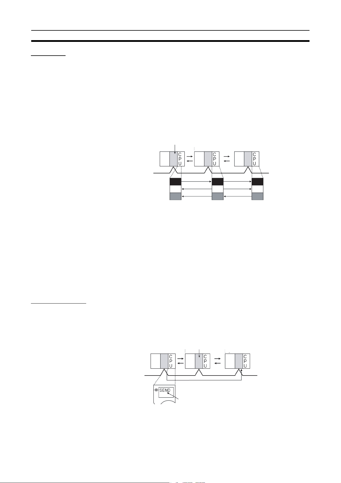
Data Links
Data links allow the constant sharing of data in predetermined data areas
between nodes, between PLCs, or between a PLC and an IBM PC/AT or
compatible computer on the network. Data links do not require the use of
communications programs on the PLC (CPU Unit) or IBM PC/AT or compatible computer. Data written in the send area of the local node will be automatically sent to the receive area of other nodes.
The I/O area (CIO area), link area (LR area), DM Area area (DM area), and
extended DM Area area (EM area) can be freely set in the send or receive
area. (The area used for sending or receiving data using the data link function
is called “data link area.”)
The data link area can be set automatically or manually.
Controller Link Unit
PLC
Constant data exchan
PLC
PLC
sharin
Automatic Setting Used for simple data link processing. Data link can be performed by simply
setting parameters in the DM area of the PLC.
Send data size per node is the same for all nodes. All nodes participating in
the data link share the same data.
Manual Setting Used for flexible data link processing depending on each system.
Using the Controller Link Support Software, individual data link tables can be
set for each node and the data link area can be freely allocated for each node.
Send data size per node can be freely set. It is also possible to set nodes for
only send or receive data. With the Controller Link Unit, the data link can be
set to receive only a part of the data link area of other nodes.
Message Service
This function controls data transmission with particular nodes, reading or writing of status data, changing of operation modes, etc., by executing communications instructions on a program. The communications instructions include
SEND/RECV instructions for data transmission and CMND instructions for
issuing various commands.
PLC
Controller Link Unit
PLC
PLC
Data transmission (under certain conditions)
as required
Communications instruction
User program
6
Overview Section 1-1
k
SEND/RECV The SEND or RECV instruction sends or receives data in an area of a particu-
lar node.
The SEND instruction sends data from an area of the local node and writes to
an area in the designated node.
The RECV instruction requests the designated node to send area data and
writes the data to the local node.
CMND The CMND instruction issues a command to read or write data of other nodes,
control, or read error logs. With the Controller LInk Unit, OMRON’s command
protocol called “FINS commands” is used.
Note Since the C200HX/HG/HE PLCs do not support the CMND instructions, arbi-
trary commands cannot be issued.
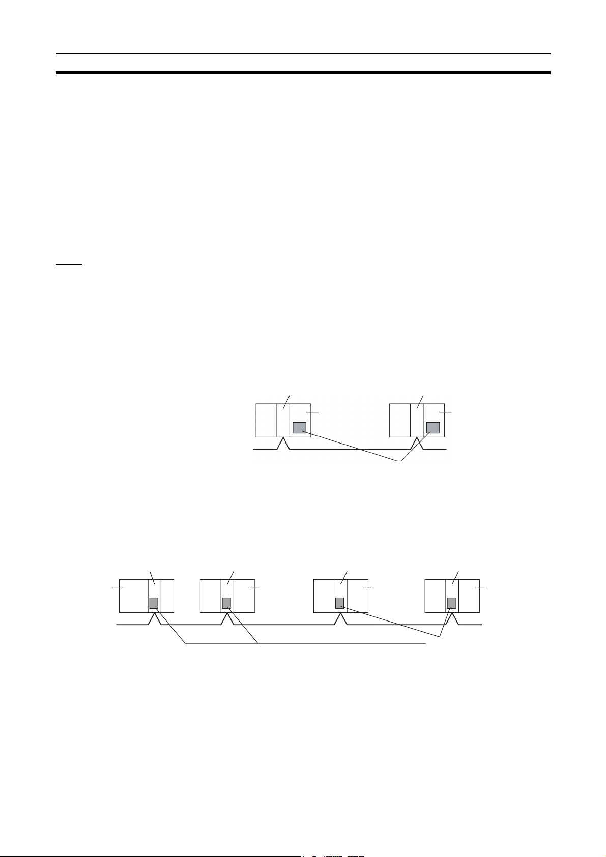
RAS
RAS performs real-time monitoring of the network status. If an error occurs in
the network, RAS records and displays the time and contents of the error.
Status Area Data Link Status Area
When the data link function is used, the data link status is reflected in the data
link status area of the PLC.
Network Status Area Other than the Data Link:
The network status such as the state of node participation is reflected in the
status area of the PLC.
Controller Link Unit
CPU Unit
Controller Link Unit
CPU Unit
Status Area
• Data link status
• Status other than the data lin
Error Log The error log function records contents (codes) and times of errors that occur
in the network into the RAM or EEPROM, up to the maximum of 39 errors.
The recorded errors can be read using the Controller Link Support Software
or the message service function.
Controller Link UnitController Link Unit Controller Link UnitController Link Unit
CJ-series
CPU Unit
CS-series
CPU Unit
C200HX/HG/
HE CPU Unit
Error log table
CVM1, CVseries CPU
Unit
7

Overview Section 1-1
1-1-2 Features
The Controller Link Network has the following features to meet the various
requirements of FA sites.
Data Links
Flexible and efficient data links can be created for large capacities of data as
listed below.
Item Specifications
Number of send words
per node
Number of send and
receive words per node
Data links can be automatically set, or they can be set by the user to freely
change the sizes of the data areas used. A data link can also be created so
that one node receives only part of the data sent from another node. This
function enables users to receive only the required data, thereby increasing
data link efficiency.
Message Service
The message service can send and receive up to 2,012 bytes of data (including the FINS header), allowing high volumes of data to be sent and received
without having to split it up.
1,000 max.
C200HX/HE/HG, CVM1, CV-series, and CQM1H-series PLCs: 8,000 max.
CS/CJ-series PLCs: 12,000 max.
IBM PC/AT or compatible: 32,000 max. (PCI or ISA Board)
Twisted-pair Cable or Optical Fiber Cable Connection
The Controller Link Units can be connected to the network using either
shielded twisted-pair cables or optical fiber cables. Select the system that
suits your application.
Features of Twisted-pair Cable
Twisted-pair cable is easy to connect and maintain. The cable can be processed much more easily than coaxial or optical cable, thereby reducing the
cost of tools and assembly time.
Connections are made to a terminal block on the Controller Link Unit and to a
special connector on the Controller Link Support Board for easy system
assembly and modification.
The network is equipped with the required terminating resistance built into the
Units allowing the terminating resistance to be easily set at both ends of the
network using a simple switch.
Features of Optical Fiber Cable
Optical Fiber Cable has superior noise resistance, so this system can provide
highly reliable communications even in very noisy conditions.
The communications distance can be up to 20 km total (1 km max. between
nodes) if H-PCF cable is used and up to 30 km total (2 km max. between
nodes) if GI cable is used, which allows long-distance or large-scale networks.
Once the Optical Fiber Cable has been fitted with special connectors, the
cables can be easily connected or disconnected.
8

Overview Section 1-1
Compatible with Different Node Configurations
The following Controller Link Units are available for communications between
different models. It must be noted, however, that the wired system and optical
system cannot exist in one Controller Link Network.
Wired System
• Controller Link Unit for CS/CJ-series Programmable Controllers
• Controller Link Unit for C200HX/HG/HE Programmable Controllers
• Controller Link Unit for CVM1 and CV-series Programmable Controllers
• Controller Link Unit for CQM1H-series Programmable Controllers
• Controller Link Support Board for IBM PC/ATs or compatibles (ISA or
PCI bus)
Flexible Inter-network Connections
The Controller Link Network can connect to other networks (Ethernet, SYSMAC NET, SYSMAC LINK, and another Controller Link network) via CVM1,
CV-series, CS-series, or CJ-series PLCs. By installing a Communications Unit
for the Ethernet, SYSMAC NET or SYSMAC LINK on the same CS/CJ-series
or CV-series PLC as a Controller Link Unit, a message service can be created
with nodes in interconnected networks through the CVM1 or CV-series PLC.
Up to three network levels are possible.
Note CS/CJ-series PLC cannot be connected directly to SYSMAC NET networks
and CJ-series PLC cannot be connected directly to SYSMAC LINK networks
The programming and monitoring of other PLCs on the network can be conducted from Programming Devices connected to the PLC’s CPU Unit. Internetwork connections are possible in this case also and can cover up to three
network levels.
Improved Error Handling
An error log enables quick handling of errors by recording the time the error
occurred and error details. The current Controller Link Unit and Support Board
status are also available, as are the data link and network status.
When an error occurs in the polling node that controls the Controller Link Network, another node automatically becomes the polling node. This prevents an
error at a single node from influencing other nodes on the network, achieving
a highly reliable system.
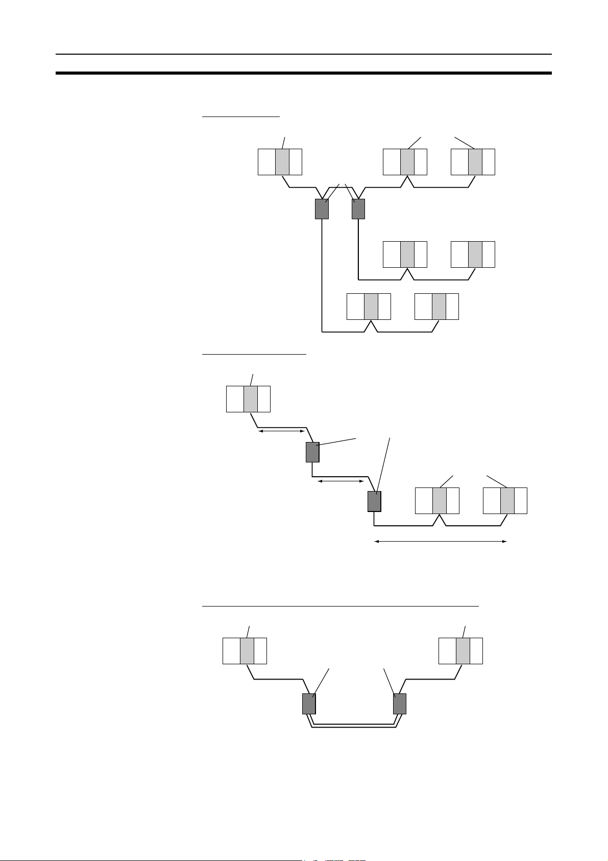
Using Repeater Units for T-Branches, Network Extensions, Network Expansions,
Converting Network Sections to Optical Fiber, and Device Modularization
T-Branches enable greater wiring freedom during layout, restructuring, and expansion of
networks.
Wire-to-Wire Repeater Units enable Controller Link T-Branches. T-Branches
provide the following advantages:
• Cabling can conform to the layout of equipment.
• It is possible to add nodes by adding or inserting Repeater Units at
branch points of an existing wired Controller Link system.
• If Repeater Units are installed at likely future branch points in the network
in advance, new nodes can be added by simply connecting them to these
Repeater Units.
9

Overview Section 1-1
The total length of wired networks can be extended.
At a baud rate of 2 Mbps, conventional wired networks can be up to 500 m
long. By using two Repeater Units, this can be extended to a maximum of
1.5 km.
The maximum number of nodes can be extended to 62 for wired networks.
By combining version-1 Controller Link Units/Support Boards and a Repeater
Unit, it is possible to construct networks containing up to 62 nodes.
Improved noise resistance through the use of optical cabling.
By installing two Wire-to-Optical Repeater Units, optical cabling can be used
for sections of the network that are the source of noise.
Devices can be modularized.
• Devices can be modularized according to Repeater Units, making wiring
easier when adding, removing, or modifying devices.
• When starting up devices, components can be added to the network and
debugged as they are completed.
Features and Functions of Version-1 Models
The following features and functions apply to the CS1W-CLK21-V1 and
CJ1W-CLK21-V1 Controller Link Units and the 3G8F7-CLK21-V1 Controller
Link Support Board only.
Up to 62 nodes can be connected.
Overview
When a CS1W-RPT01 Repeater Unit is used, the maximum number of nodes
that can be used in the network increases to 62. (The previous limit was 32.)
Method
Use Repeater Units and turn ON bit 11 (Wired Network 62 Node Enable Bit) in
the DM Parameter Area software switch D30000 + 100
to enable a maximum of 62 nodes.
Restrictions
The maximum 62 nodes cannot be achieved if version-1 models and pre-version-1 models are used together in the same network.
Automatic data link creation is possible with 1:N allocations.
Overview
It is possible to perform unequal 1:N allocations of data between nodes with
automatic data link creation. This makes it easy to perform data links that formerly required the user to manually edit data link parameters.
The following four automatic data link creation patterns can be used:
• Equality layout (the previous pattern)
• 1:N allocation, common type
• 1:N allocation, 1 to 1 type
• 1:N allocation, chain type
× Unit No. of all nodes
10
Method
Allocation addresses and sizes are all specified using the Automatic Data Link
Creation Parameters (D30000
Area. These values can be set using the CX-Net in the CX-Programmer version 3.2 or later.
× Unit No. + 12 to 20) in the DM Parameter
Specifications and Configurations Section 1-2
pp
Objective
This function is effective in applications that collect data from slave PLCs into
a master PLC.
Restrictions
Automatic data link creation with 1:N allocations cannot be performed if version-1 models and pre-version-1 models are used together in the same network.
Change manually created data link tables during data link operation.
Overview
It is possible to modify a manually created data link table while data links are
running.
Note This is possible only with manually created data link tables. Any attempt to
change automatically created data link tables when data links are running will
fail with an error message saying that the tables cannot be edited during data
link operation will be displayed.
Method
This function can be set using the CX-Net in CX-Programmer version 3.2 or
later.
Objectives
• In systems that operate non-stop and cannot be turned OFF, this function
makes it possible to change the data link table to accommodate the addition of new nodes and to transfer data link tables without having to stop
manually set data link communications.
• If this function is combined with the use of Repeater Units to add network
nodes, it becomes possible to construct systems of greater flexibility.
Operation
When a node is being modified online, this function temporarily stops refreshing of data link data until modifications have been completed.
Nodes will participate in data links after changes to the data link table have
been completed.
1-2 Specifications and Configurations
1-2-1 System Configuration
Wired Systems Wired systems can be used to connect CS/CJ-series PLCs, C200HX/HG/HE
PLCs, CVM1 PLCs, CV-series PLCs, and IBM PC/AT or compatible computers.
CS1W-CLK21-V1
Controller Link Unit
CS-series
PLC
C
P
U
CJ1W-CLK21-V1
Controller Link Unit
CJ-series PLC
C200HX/HG/HE
PLC
C
P
U
C200HW-CLK21
Controller Link Unit
CVM1, CV-series
PLC
C
P
U
CVM1-CLK21
Controller Link Unit
C
P
U
CQM1H-CLK21
Controller Link Unit
CQM1H-series
PLC
C
P
U
IBM PC/AT or
compatible
Twisted-pair cable
3G8F7-CLK21-E-V1
Controller Link
ort Board
Su
11
Specifications and Configurations Section 1-2
Connecting Repeater Units Using Twisted-pair Cable in Wired Systems
T-Branch Wiring
Wired Controller Link Unit Wired Controller Link Unit
CS1W-RPT01
Repeater Units
Twisted-pair cable
Twisted-pair cable
Long-distance Wiring
Wired Controller Link Unit
Twisted-pair cable
500 m max.
(See note.)
500 m max.
(See note.)
CS1W-RPT01
Repeater Units
Twisted-pair
cable
Wired Controller Link Unit
Twisted-pair cable
500 m max. (See note.)
Note: At 2 Mbit/s
Converting Part of the Transmission Line to Optical Fiber
Wired Controller Link Unit Wired Controller Link Unit
CS1W-RPT02 or
CS1W-RPT03
Repeater Units
12
Twisted-pair cableTwisted-pair cable
Optical cable (H-PCF or GI)
Two Repeater Units of the same model must be used when part of the transmission line uses optical fiber.
Specifications and Configurations Section 1-2
Maximum Configuration of 62 Nodes
Wired Controller Link Unit
The following Controller Link Units/Support Boards must be used to construct
a network with more than 32 nodes:
CS1W-CLK21-V1
CJ1W-CLK21-V1
3G8F7-CLK21-E-V1
Note 1. The network will not operate correctly unless all nodes within the network
use the above Units/Boards.
2. Only node addresses 1 through 32 can be used on networks for which 62
nodes have not been enabled.
1-2-2 General Specifications
Twisted-pair cable
32 nodes max.
CS1W-RPT01
Repeater Unit
Wired Controller Link Unit
Twisted-pair cable
32 nodes max.
General specifications are the same for the C200HX/HG/HE, CS-series, CJseries, CVM1, CV-series, and CQM1H-series PLCs.
13

Specifications and Configurations Section 1-2
1-2-3 Communications Specifications
Wired System
Items Specifications
Communications method N:N token bus
Code Manchester code
Modulation Baseband code
Synchronization Flag synchronization (conforms to HDLC frames)
Transmission path form Multi-drop bus
Baud rate and maximum
transmission distance
Media Specified shielded twisted-pair cable
Node connection method PLC: Connected to a terminal block
Maximum number of nodes 32 or 62 nodes (See note 2.)
Communications functions Data links and message service
Number of data link words
Data link areas Bit-access areas (IR, AR, LR, CIO), DM Area (DM), and extended DM Area (EM)
Message length 2,012 bytes max. (including the header)
RAS functions Polling node backup function
Error control Manchester code check
The maximum transmission distance varies with the baud rate as follows:
2 Mbps: 500 m
1 Mbps: 800 m
500 Kbps: 1 km
Number of signal lines: 2, shield line: 1
IBM PC/AT or compatible: Connected via a special connector (included)
Transmission area per node: 1,000 words (2,000 bytes) max.
Data link area in one C200HX/HG/HE, CVM1, CV-series, or CQM1H-series PLC (send/
receive): 8,000 words (16,000 bytes) max.
Data link area in one CS/CJ-series PLC (send/receive):
12,000 words (24,000 bytes) max.
Data link area in one IBM PC/AT or compatible (transmission/reception):
32,000 words (64,000 bytes) max.
Number of data link words in one network (total transmission):
32,000 words (64,000 bytes) max.
Self-diagnosis function (hardware checking at startup)
Echoback test and broadcast test (using the FINS command)
Watchdog timer
Error log function
16
CRC check (CCITT X
+ X12 + X5 + 1)
14
Note 1. The maximum distance between nodes depends on the connector and ca-
ble processing methods.
2. At least one Repeater Unit is required to construct networks that uses a
node address higher than 32. The following Controller Link Units/Support
Boards must also be used, and the Wired Network 62 Node Enable Bit of
the DM Parameter Area software switch of all nodes must be turned ON
(62 nodes max.).
CS1W-CLK21-V1, CJ1W-CLK21-V1, and 3G8F7-CLK21-V1
3. Only node addresses 1 through 32 can be used on networks for which 62
nodes have not been enabled.

Specifications and Configurations Section 1-2
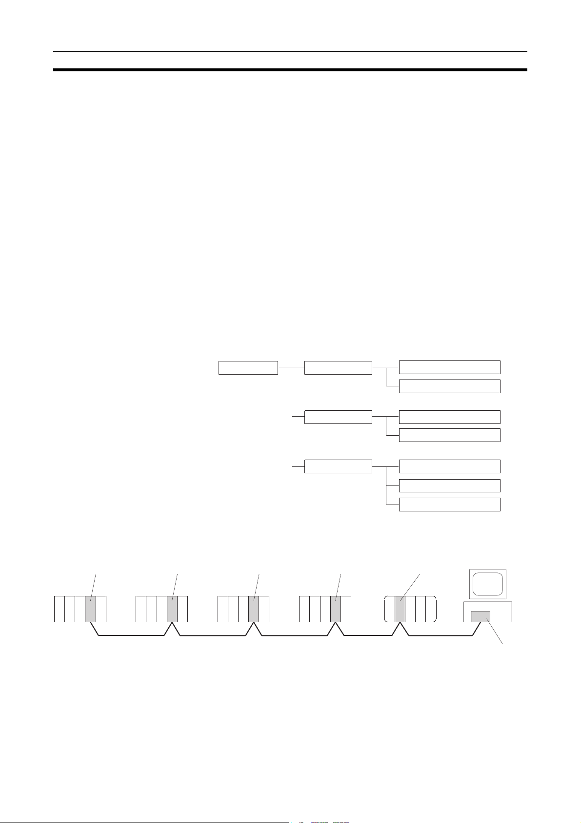
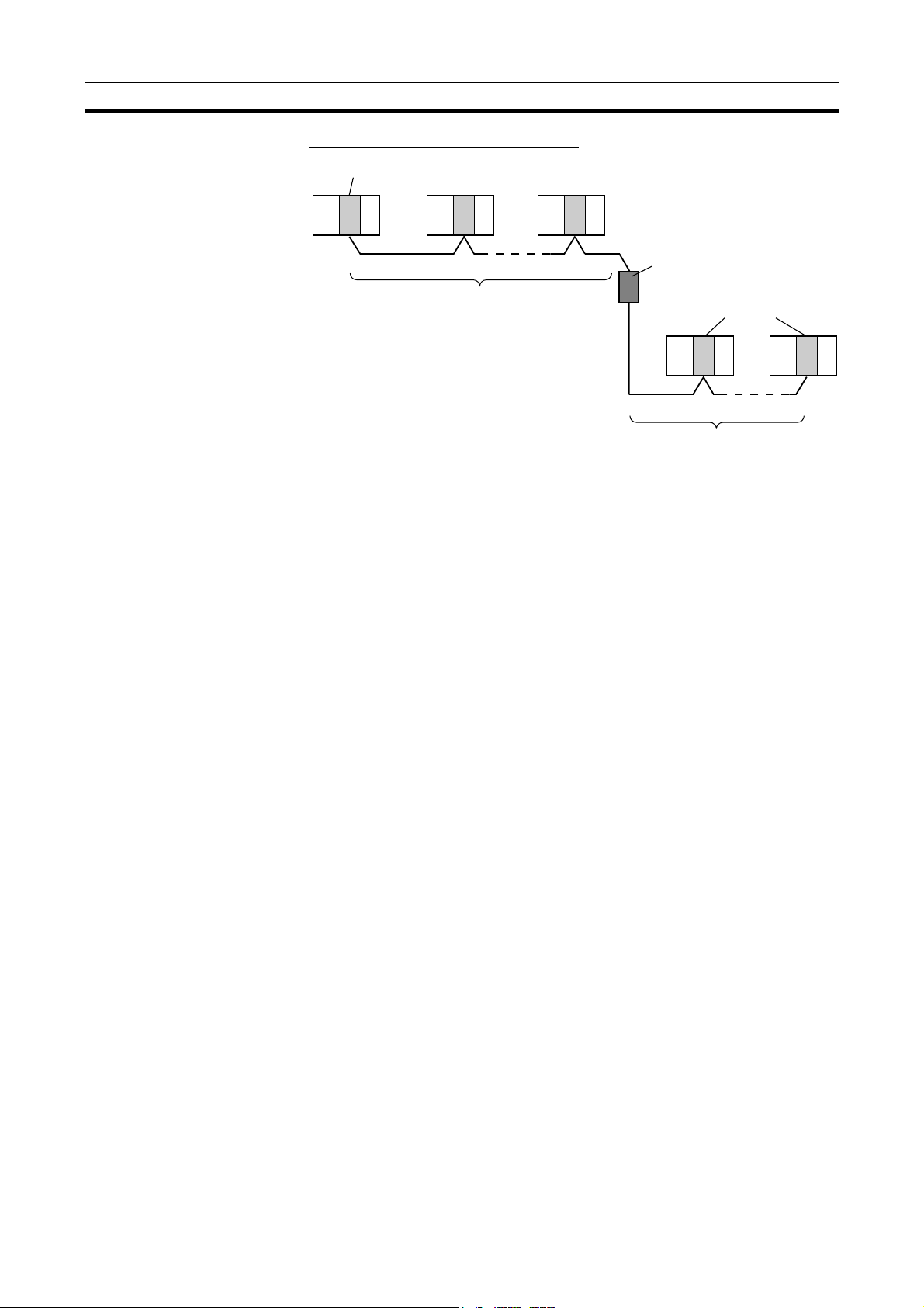
Communications Specifications when Using the CS1W-RPT01 Repeater Unit in a Wired
Network
Item Within 1 segment (See
note 1.)
Transmission path form Multi-drop Tree type (Connection of
Baud rate and maximum transmission distance (See note 2.)
Maximum number of nodes Total number of Control-
Maximum number of Repeater
stages (See note 4.)
2 Mbps: 500 m
1 Mbps: 800 m
500 Kbps: 1 km
ler Link Units + Repeater
Units: 32 nodes (See
note 5.)
--- 2 stages
Note 1. Specifications within a segment are identical to the specifications of a
Wired Controller Link Network.
2. Maximum transmission distance: Total length of cables in the longest path
connecting any two nodes.
3. A maximum of 62 nodes is possible only when using CS1W-CLK21-V1,
CJ1W-CLK21-V1 and 3G8F7-CLK21-V1 Units.
4. Maximum number of Repeater stages: The maximum number of Repeater
Units that can be inserted into the path connecting any two nodes. For
wire-to-optical connection, two Repeater Units make up a single set, which
is counted as a single Repeater stage.
5. The Repeater Units each have a unique node address. Up to 32 Units,
consisting of Controller Link Units and Repeater Units, can be connected
within a single segment.
Entire network
segments with Repeaters)
2 Mbps: 1.5 km
1 Mbps: 2.4 km
500 Kbps: 3.0 km
Controller Link Units/Support Boards (See note 3.):
62 nodes
Wire
Optical
fiber
cable
: Controller Link Unit/Support
Board
: Wire-to-wire Repeater Unit
: Wire-to-optical Repeater Unit
(two Units used in a pair)
: Range of a single segment
Note: The Repeater Unit will be
counted in the number of
nodes for each segment that
it is connected to.
Specifications of Optical Fiber Cables Used with Wire-to-Optical
Connections
Item H-PCF type GI type
Optical fiber cable H-PCF 200/230 µm two-
Maximum transmission
distance (See note 2.)
core cable
Adhesion-polished: 1 km
Crimp cut: 800 m
GI 50/125 µm two-core cable
or GI 62.5/125 µm two-core
cable
50/125 µm: 1 km
62.5/125 µm: 2 km
15

Specifications and Configurations Section 1-2
1-2-4 Controller Link Unit Models and PLCs
Wired System
There are five Controller Link Units: One for CVM1 and CV-series PLCs, one
each for CS-series and CJ-series PLCs, one for the C200HX/HG/HE PLC,
and one for CQM1H-series PLCs.
Item Specifications
Model CS1W-CLK21-V1 CJ1W-CLK21-V1 C200HW-CLK21
External appearance
C
L
K
2
1
RUN
ERC
INS
SD
TER
ERH
M/A
LNK
RD
4
5
3
6
2
7
1
8
U
N
IT
0
9
F
A
E
B
D
C
No.
3
2
4
1
5
NODE
0
6
9
7
8
No.
1
x10
3
2
4
1
5
0
6
9
7
8
ON
0
x10
1
ON
SW1
2
1
BAUD
RATE
2
TER SW
ON
BD H
BD L
SHLD
Installation
devices
None required. None required. C200HW-COM01/04 Commu-
nications Board and
C200HW-CE001/002/012 Bus
Connection Unit
PLC CS-series PLCs CJ-series PLCs C200HX/HG/HE PLCs
(Except C200HE-CPU11(-Z))
Max No. of Units
per PLC
Installation site Install onto a CPU Backplane or
Storage location
4 maximum including optical
models
CPU
CPU Backplane
Unit
4 maximum on CPU or Expansion Rack
2 maximum
CPU Backplane
2 max.
2/3/5/8/10 slots
Expansion
Of these
slots,
installation
is possible
in up to 4
slots.
Backplane
3/5/8/10 slots
CS-series Expansion Backplane
(Classified as a CPU Bus Unit.)
Install onto a CPU Rack or
Expansion Rack (Classified as a
CPU Bus Unit.)
Install onto a CPU Backplane. (Classified as a Special
I/O Unit for communications.)
CPU Bus Unit Area (in the CPU Unit parameter area) Controller Link Unit
CPU
Unit
for network
parameters
Storage location
for routing tables
CPU Unit parameter area DM 6450 to DM 6499 in CPU
Unit
Weight 400 g 110 g 400 g
Current con-
330 mA 350 mA 300 mA
sumption
16

Specifications and Configurations Section 1-2
Item Specifications
Model CVM1-CLK21 CQM1H-CLK21
External
appearance
Installation
None required. None required.
devices
PLC CVM1 and CV-series PLCs CQM1H-CPU51/61
Max No. of
Units per PLC
Installation site Install onto a CPU Backplane or
Storage location for net-
4 maximum 1 maximum
CPU Backplane
3/5/10 slots
Expansion CPU
Backplane
11 slots
CPU
Unit
Of these
14, 16, or
21 slots,
installa
tion is
possible
in up to 4
slots.
Power Supply
Unit
Connect
here.
Connected as a CommuniExpansion CPU Backplane (Classified as a CPU Bus Unit.)
CPU Bus Unit Area (in the CPU Unit
cations Unit between Power
Supply Unit and CPU Unit.
Controller Link Unit
parameter area)
CPU
Unit
work
parameters
Storage location for routing
CPU Unit parameter area DM 6450 to DM 6499 in
CPU Unit
tables
Weight 550 g 200 g
Current con-
300 mA 290 mA
sumption
Note A Controller Link Support Board can be installed into an IBM PC/AT or com-
patible computer to connect the computer to the network. Refer to the Controller Link Support Boards Operation Manual (W307) for details.
17

Specifications and Configurations Section 1-2
Functional Differences between Version-1 and Pre-version-1 Models
Item Pre-version-1 models Version-1 models
Model Controller Link
Unit
Controller Link
Support Board
Automatic data link creation
Changing manually created data link tables during operation
Maximum number of
nodes that can be connected
Combined usage Possible (See note.)
Note Automatic data link creation with 1:N allocation and 62-node configurations
cannot be used if version-1 models are used together with pre-version-1 models.
CS1W-CLK21 and
CJ1W-CLK21
3G8F7-CLK21 3G8F7-CLK21-V1
Equality layout only Either equality layout or 1:N allo-
Not supported. Supported (The data link tables
32 nodes 62 nodes
CS1W-CLK21-V1 and CJ1WCLK21-V1
cation (common type, 1 to 1 type,
or chain type) can be selected.
can be changed with active data
links.)
A CS1W-PRT01 Repeater Unit is
required.
1-2-5 Devices for Connection
Communications Cables
Note Use the special connector provided with the Board to connect the Controller
To set up a Controller Link Network, the following devices are needed in addition to a Controller Link Unit and a PLC.
The following shielded twisted-pair cables are recommended for Wired Controller Link Network connections.
Model Manufacturer Remarks
Li2Y-FCY2 x 0.56 qmm Kromberg & Schubert,
Komtec Department
1 x 2 x AWG
Tr.CUSN + PVC
#9207 Belden USA company
ESVC 0.5 x 2 C-1362 Bando Densen Co. Japanese company
ESNC 0.5 x 2 C-99-087B Nihon Electric Wire &
– 20PE +
Draka Cables Industrial Spanish company
Cable Co.
German company
Japanese company
Link Support Board to the network.
18

Specifications and Configurations Section 1-2
Repeater Units (when Required)
The following Repeater Units can be used to facilitate the use of T-Branch wiring, long-distance wiring, and the addition or removal of nodes.
Three types of Repeater Unit are available for use with different transmission
line types (i.e., connection methods).
Item Specifications
Model CS1W-RPT01 CS1W-RPT02 CS1W-RPT03
External appearance
Supported Units/
Boards
Transmission line Twisted-pair cable H-PCF cable (optical
All Controller Link Units/Boards for wired networks.
Note To construct a network that can contain up to 62 nodes, it is necessary to use version-1
models, which support 62 nodes.
two-core cable)
GI cable (optical twocore cable; 62.5/125 µm,
50/125 µm)
19

Specifications and Configurations Section 1-2
Item Specifications
Transmission line
format
Multi-drop
Tr ee
T-Branch Wiring
Repeater Unit
Long-distance Wiring
500 m max.
(at 2 Mbit/s)
Repeater Unit
500 m max.
(at 2 Mbit/s)
1:1 type 1:1 type
Partial Conversion to Optical
Wire cable Wire cable
Repeater Unit
Optical cable
Repeater Unit
62-node Configuration
31 nodes max.
Repeater Unit
31 nodes max.
Installation Units are not mounted on the PLC, but are attached to DIN Track or screw-mounted.
Weight 126 g 113 g (excluding mount-
ing bracket)
116 g (excluding mounting bracket)
Current consumption 24 V DC at 60 mA max. 24 V DC at 60 mA max. 24 V DC at 70 mA max.
Power supply volt-
24 V DC
age
Allowable power
20.4 to 26.4 V DC (24 V DC −15 to 10%)
supply voltage range
Inrush current 2.5 A max. at 24 V DC (5 ms after startup)
Note 1. Repeater Units do not use a node address.
2. See
Connection Procedure for an explanation of how Repeater Units are
used.
3. The following Power Supply Unit is recommended: OMRON S82K Series
Relay Terminal Blocks
The following Relay Terminal Block can be used to make maintenance easier
by facilitating replacement of the Controller Link Unit after system operation
has begun.
Name Model Remarks
Relay Terminal Block for
Wired Controller Link Units
CJ1W-TB101 Cannot be used on the nodes
on the ends of the network
20

Specifications and Configurations Section 1-2
k
Note Normally, the communications cable must be disconnected from a Wired Con-
troller Link Unit to replace it. Doing this, however, will interrupt communications on the network, requiring that all node be turned OFF to ensure safety
before replacing a Unit. With the above Relay Terminal Block, a Controller
Link Unit can be replaced by turning OFF only the specific Unit being
replaced, i.e., without turning OFF any other Units. The communications
cables are left connected to the Relay Terminal Block and only the Relay Terminal Block is removed from the Controller Link Unit. (The built-in terminating
resistance connected at the Units at the end of the network prevents using the
Relay Terminal Block on the end Units.) Refer to
Terminal Block
for details on using the Terminal Relay Block.
Appendix C Using the Relay
1-2-6 Programming Devices
A Programming Device for the PLC, the Controller Link Support Software, or
CX-Programmer are needed to use a Controller Link Network.
Programming Device for the PLC
One of the following Programming Devices is necessary when using the automatically setting data links or the message service.
Programming
Console
Start-up node
or
CPU Unit
Controller Lin
+
IBM PC/AT or
compatible
CX-Programmer
Software switches (DM Area)
The following operations are possible.
• Selecting manual or automatic setting for data links.
• Setting the data link mode to “automatic” (software switch setting).
• Starting/stopping data links (Start Bit: ON/OFF)
• Programming for the message service.
• Reading (monitoring) the network status.
Programming
Device
CX-Programmer
(for PLC)
SYSMAC Support
Software (for PLC)
CV Support Software (for PLC)
SYSMAC-CPT
(for PLC)
External
appearance
Model Applicable PLCs
WS02-CXP
C500-ZL3AT1-E C200HX/HG/HE and
CV500-ZS3AT1-EV2 CVM1 and
WS01-CPTB1-E C200HX/HG/HE and
@@-E
CS/CJ-series,
C200HX/HG/HE,
CVM1-series, and
CQM1H-series PLCs
CVM1 PLCs
CV-series PLCs
CVM1 PLCs
21

Specifications and Configurations Section 1-2
Programming
Device
Programming
Console
External
appearance
Note For automatic data link creation with 1:N allocations or when changing data
link tables while the data link is active (CS1W-CLK21-V1 and CJ1W-CLK21V1), use the CX-Net in CX-Programmer version 3.2 or later.
Controller Link Support Software (Version 2.00)
The Controller Link Support Software can be used to manually set data links,
to set Controller Link parameters, and to monitor the Controller Link Network.
The Controller Link Support Software is run on a personal computer connected to a C200HX/HG/HE, CVM1, or CV-series PLC or a personal computer in which a Controller Link Support Board has been mounted.
• Setting the data link mode to “manual” (creating and storing data link
tables).
• Starting/stopping data links.
• Reading (monitoring) network status.
• Reading error logs.
• Setting routing tables.
• Testing the Network.
• Changing network parameters.
• Reading the network connection configuration data and status (in tokenring mode only).
Model Applicable PLCs
CQM1-PRO01-E
C200H-PRO27-E
CVM1-PRS21-EV1 CVM1 and
C200HX/HG/HE,
C200H/C200HS,
CQM1, and
CQM1H-series PLCs
CV-series PLCs
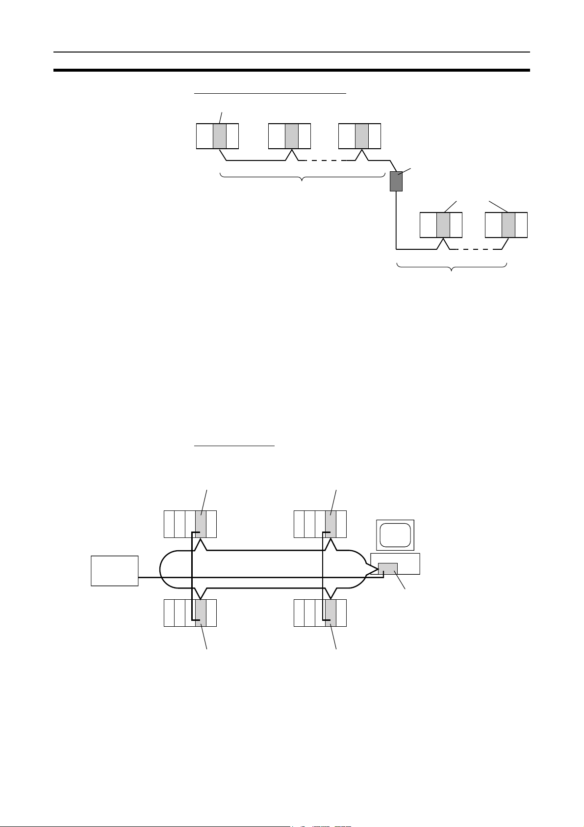
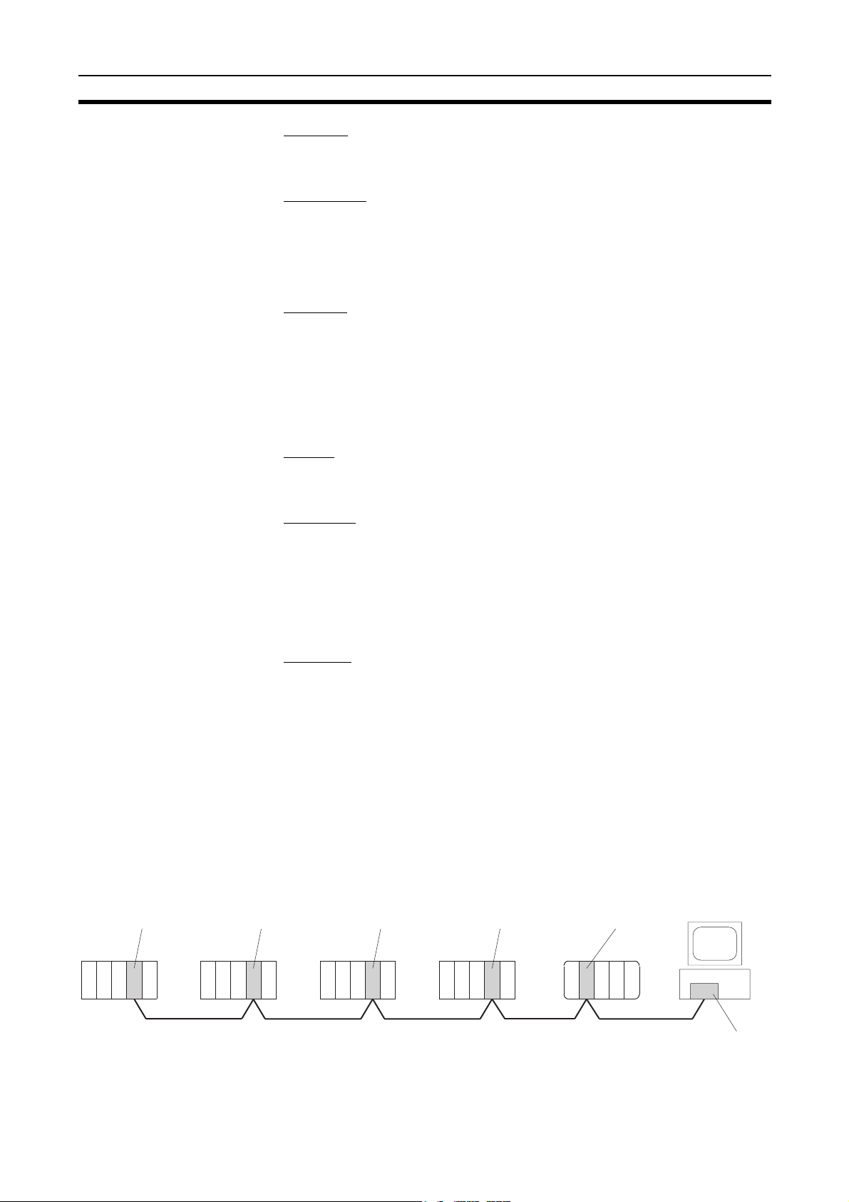
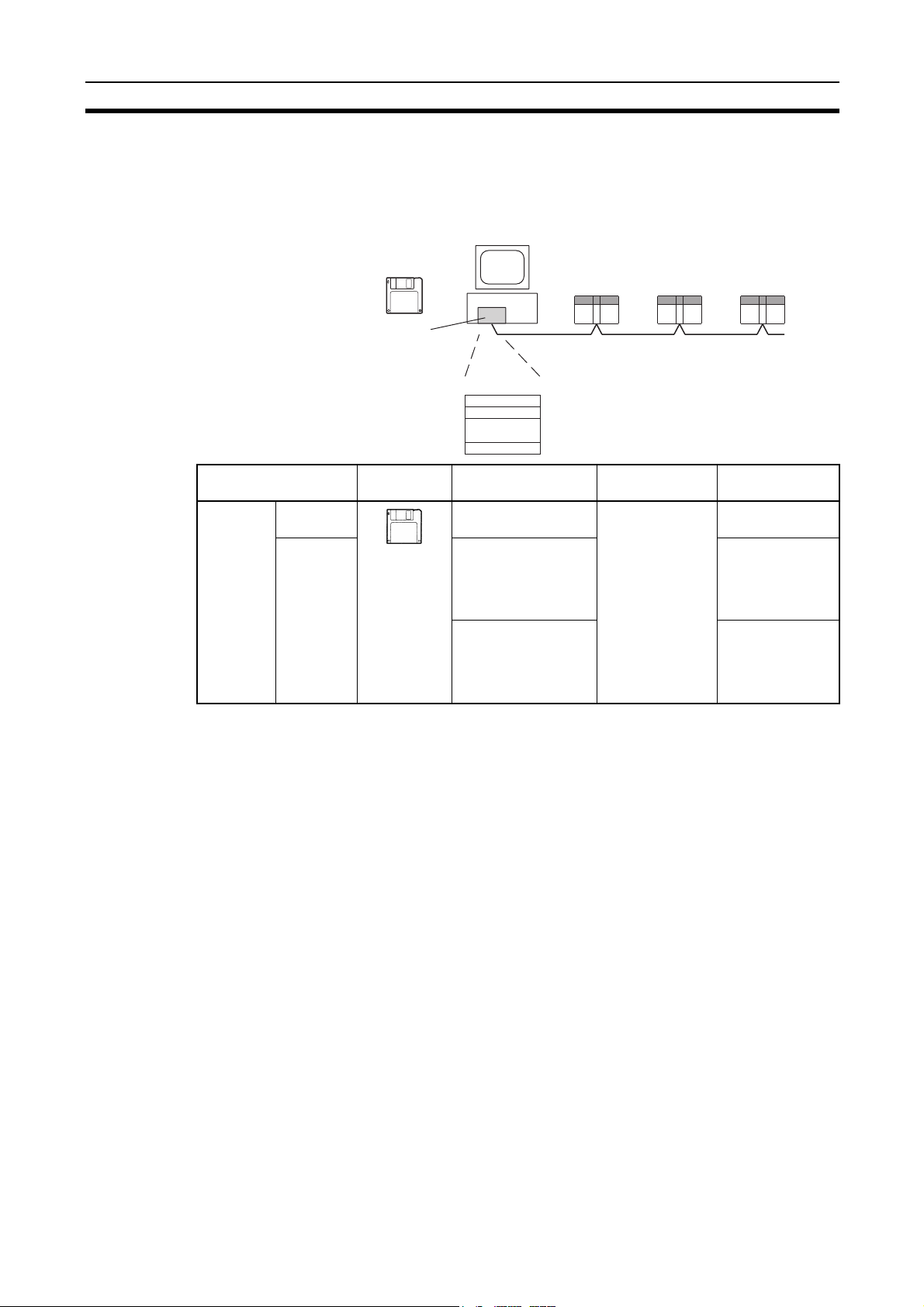
Using an Independent
Computer
IBM PC/AT or
compatible
Setting data link tables
…
A computer that is not part of the Network can be used to control the Controller Link Network.
C200HX/HG/HE and
+
Controller Link
Support Software
Nodes
RS-232C
Transmissions
CS1-series PLCs
Nodes
RS-232C
C200HX/HG/HE,
CVM1, and CV-series
PLCs
CQM1H-series PLCs
Controller
Link Unit
CPU Unit
Controller
Link Unit
CPU Unit
CVM1 and CV-series PLCs
Nodes
CS1-series PLC
Controller
Link Unit
CPU Unit
Note 1. The Controller Link Support Software cannot be connected to a CS/CJ-se-
ries PLC. It is possible to monitor and set a Controller Link Unit on a CS/
CJ-series via the network by connecting the computer running the Controller Link Support Software to a C200HX/HG/HE, CVM1, CV-series, or
CQM1H-series PLC.
22
Specifications and Configurations Section 1-2
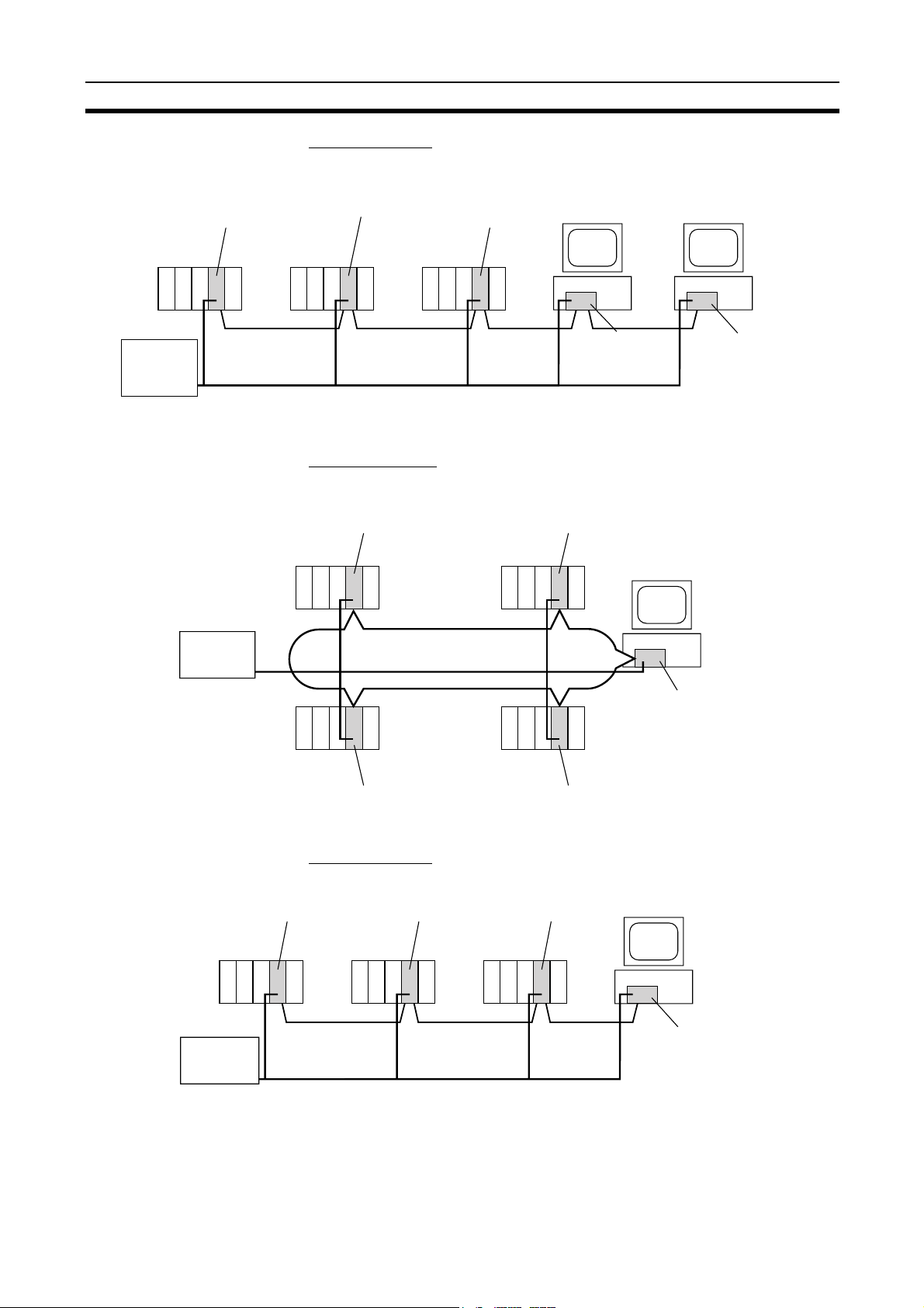
2. The Controller Link Support Software can be used as a part of the SYSMAC Support Software.
Using a Computer Node A computer that is a node on the Network can also be used to control the
Controller Link Network.
IBM PC/AT or compatible
Controller Link
Support Software
+
Controller Link
Support Board
Setting data link tables
…
Software External
Controller
Link Support Software
Purchased
separately
Provided
with Controller Link
Support
Board
Note Use Controller Link Support Software version 1.1 for an ISA Controller Link
Support Board.
The Controller Link Support Software can also be used with the Controller
Link Support Board.
appearance
Model Applicable PLCs Remarks
C200HW-ZW3AT2EV2
3G8F5-CLK21-EV2 For Controller
3G8F5-CLK11-E For IBM PC/AT or
CS/CJ, C200HX/
HG/HE, CVM1,
CV-series, or
CQM1H-series
PLC
For IBM PC/AT or
compatible
Link Support
Board (included
with the Board)
(Wired systems)
compatible
(included with the
Board) (Optical
systems)
23

Specifications and Configurations Section 1-2
g
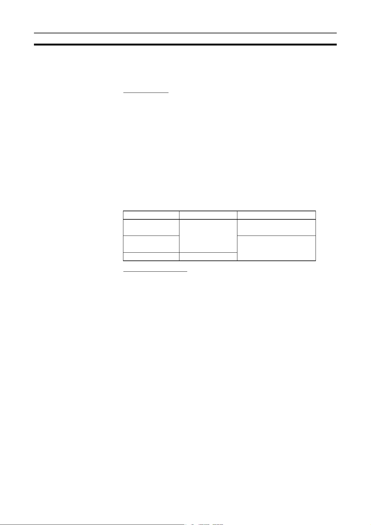
Controller Link Support Software Menu Overview
•
Menu items: •
Data Link
Set Network parameters
Edit table
•
Copy table
•
Save table
•
Retrieve table
Print table
•
Start/Stop
Routing tables
Echoback test
Broadcast test
Monitor Network
Display Error log
Display Node status
Display Board setup
Maintenance
Connection Info*
Edit PC ID
System setup
• Initialize table
• Check table
• Unit backup
• Board backup
• Initialize network parameters
• Transfer table
• Delete table
*Optical Rin
• Monitor status
• Device info set
Link Systems only.
Note 1. Refer to the Controller Link Support Software Operation Manual (W308)
for detailed operating procedures.
2. For automatic data link creation with 1:N allocations or when changing
data link tables while the data link is active (CS1W-CLK21-V1 and CJ1WCLK21-V1), use the CX-Net in CX-Programmer version 3.2 or later. Controller LInk Support Software cannot be used to perform these functions.
CX-Programmer
The CX-Net operations within the CX-Programmer is required when using
user-set data links, or when setting or monitoring detailed settings of the Controller Link Unit. This software can be used with a CS/CJ-series PLC and is
ideal for the following applications.
• Setting the data link mode to “manual” (creating and storing data link
tables).
• Starting/stopping data links.
• Reading (monitoring) network status.
• Reading error logs.
• Setting routing tables.
• Testing the Network.
• Changing network parameters.
24

Selection of Communications Functions Section 1-3
When Operating on Personal Computer as Peripheral Software
+
IBM PC/AT or
compatible
Setting data link tables
…
CX-Net in
CX-Programmer
Transmissions
When Operating on Personal Computer Connected as a Node
IBM PC/AT or compatible
CX-Net in
CX-Programmer
+
Controller Link
Support Board
Setting data link tables
…
Nodes
RS-232C
Controller
Link Unit
CPU Unit
Software External
appearance
CX-Programmer
WS02-CXP
Model Applicable PLCs
Note 1. For further details about the CX-Programmer, refer to the WS02-CXP@@-
E CX-Programmer Operation Manual.
2. Use version 1.54 or later of CX-Net in version 2.04 or later of the CX-Programmer for the CJ-series Controller Link Unit.
3. For automatic data link creation with 1:N allocations or when changing
data link tables while the data link is active (CS1W-CLK21-V1 and CJ1WCLK21-V1), use the CX-Net in CX-Programmer version 3.2 or later.
1-3 Selection of Communications Functions
Select the data link function if alarm or status data (in bits) must be constantly
shared between PLCs or between a PLC and an IBM PC/AT or compatible
computer or if the present value or set value data (in words) must be constantly shared between PLCs or between a PLC and an IBM PC/AT or compatible computer.
Select the message service function (SEND/RECV instructions or CMND
instructions) if data (in words) must be sent (or received) from one PLC to
@@-E-V3@
CS/CJ-series,
C200HX/HG/HE,
CVM1, CV-series,
and CQM1H-series
PLCs
25

Basic Procedures Section 1-4
other PLCs in other nodes or from one PLC to IBM PC/AT or compatible computers.
1-4 Basic Procedures
Preparations C200HX/HG/HE and CQM1H-series PLCs
1,2,3... 1. Perform mounting and wiring.
• Mount to the PLC.
• Connect the communications cables.
2. Set the node address on the front rotary switches.
• 01 to 32
3. Set the baud rate and operating level on the front DIP switch.
• 2 M, 1 M, or 500 Kbps
• Operating level 0 or operating level 1 (C200HX/HG/HE PLCs only)
4. Set the terminating resistance on the sliding switch.
• ON or OFF (Only the end nodes are set to ON.)
5. Connect power to all nodes.
6. Connect the Programming Device to the PLC.
7. Create I/O tables (not necessary for C200HX/HG/HE and CQM1Hseries PLCs and not necessary for CJ-series PLCs unless user-created
I/O tables have been specified).
8. Register routing tables as required.
CVM1, CV-series, and CS/CJ-series PLCs
1,2,3... 1. Perform mounting and wiring.
• Mount to the PLC.
• Connect the communications cables.
2. Set the Unit number on the front rotary switches.
• 00 to 15 (0 to F: CS/CJ-series display is in hexadecimal)
3. Set the node address on the front rotary switches.
• 01 to 32 (01 to 62) (See note a.)
4. Set the baud rate and operating level on the front DIP switch.
• 2 M, 1 M, or 500 Kbps (wired systems only)
5. Set the terminating resistance on the front slide switch.
• ON or OFF (Only the terminal node is set to ON.)
6. Connect power to all nodes.
7. Connect the Programming Device to the PLC.
8. Create I/O tables (not necessary for C200HX/HG/HE and CQM1Hseries PLCs and not necessary for CJ-series PLCs unless user-created I/
O tables have been specified).
9.
Set the Wired Network 62 Node Enable Bit in the DM Parameter Area software switches. (See note b.)
• ON (62 nodes max.) or OFF (32 nodes max.)
10. Register routing tables.
Note a) Setting 62 nodes is possible only with the CS1W-CLK21-V1 and
CJ1W-CLK21-V1.
DM Parameter Area software switches must be set.
The Wired Network 62 Node Enable Bit in the
26

Application Precautions Section 1-5
b) This setting is valid only with the CS1W-CLK21-V1 and CS1W-
CLK21-V1. Reset the power to the PLC after setting.
Data Link Procedure Set the data link mode in the data link parameters in the DM area of the star-
tup node to either automatic or manual data link creation using the Programming Device.
Manually Setting Data Links
1,2,3... 1. Register data link tables for all nodes using the Controller Link Support
Software or CX-Programmer.
2. Start the data links either using the Controller Link Support Software, CXProgrammer, or by turning ON the Start Bit from the Programming Device.
Automatically Setting Data Links
1,2,3... 1. Set the DM area of the startup node using the Programming Device.
2. Start the data links by turning ON the Start Bit from the Programming Device.
Message Service
Execute communications instructions in the program.
Procedure
1-5 Application Precautions
• Turn ON the terminating resistance switch only for the nodes at both ends
of the network and turn OFF the switch for all other nodes.
• Turn OFF the power of all the nodes on the network before connecting or
disconnecting a cable.
• Use the specified cable only.
• Set the same baud rate for all nodes on the same network.
• Be sure to set routing tables for CVM1 and CV-series PLCs. When a
CVM1 or CV-series PLC is connected to the network, set routing tables at
all the nodes.
C
C
L
P
U
K
C200HX/HG/HE PLC CVM1 or
Note Routing tables are not required if all of the CVM1 and CV-series CPU Units if
the Controller Link Network were manufactured on or after May 1996.
C
C
L
P
U
K
C200HX/HG/HE PLC
C
L
K
CV-series PLC
C
P
U
Routing tables are necessary
at all the nodes.
CLK: Controller Link Unit
CVM1 or
CV-series PLC
Manufactured after May 1996
Independent Controller Link Network
C200HX/
C
C
C
L
P
K
U
C
P
L
HG/HE
U
K
PLC
CVM1 or
CV-series PLC
C
L
K
Routing tables not
C
necessary
P
U
Manufactured after May 1996
Note The manufacturing date can be determined from the four-digit lot number on
the side of the CPU Unit.
27
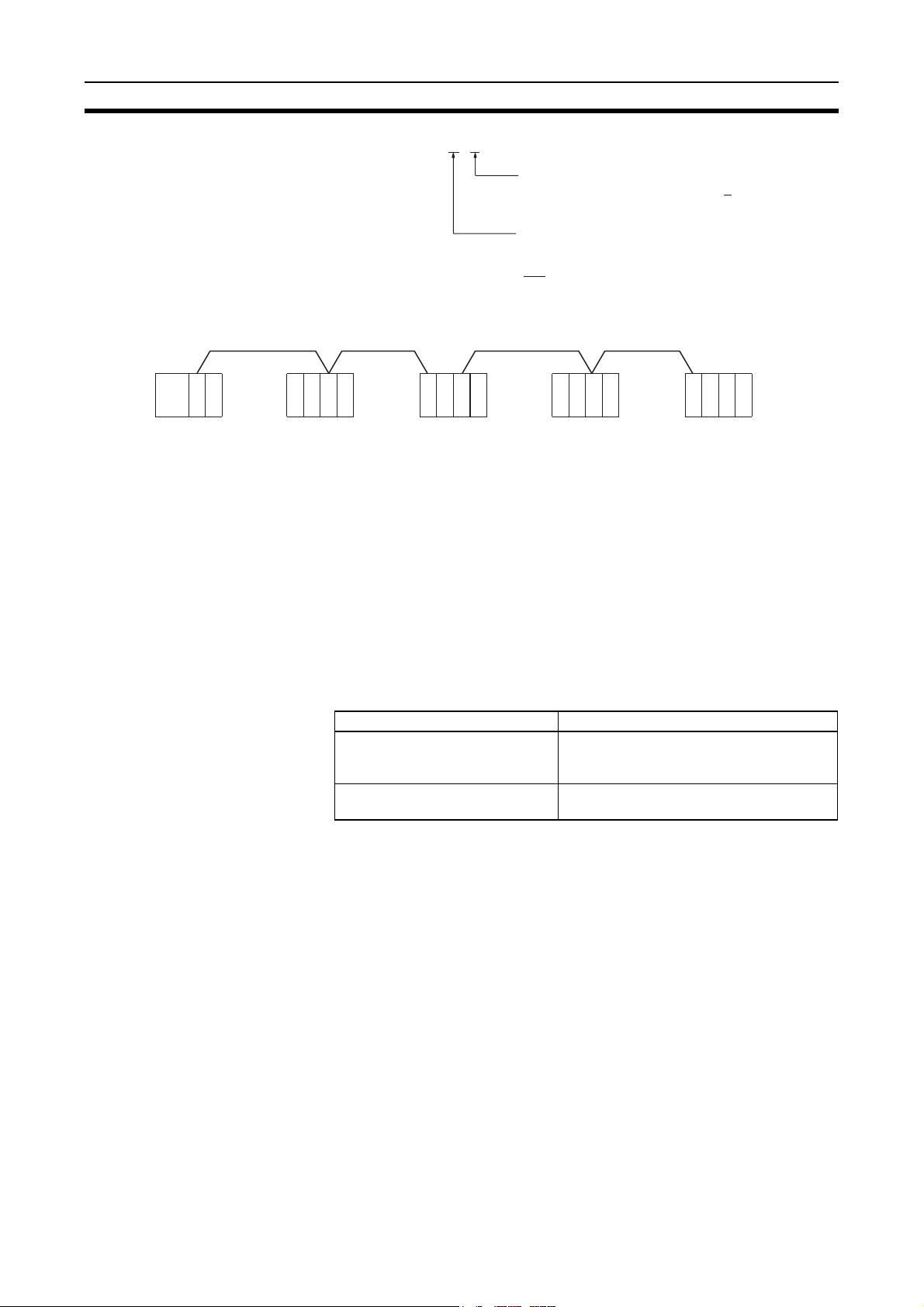
Application Precautions Section 1-5
g
Lot No.: @ @ 5 6 .....Manufactured in May 1996
Indicates the last digit of the manufacturing
year. In this example, the year is 1996.
Indicates the month of manufacture. October,
November, and December are indicated by x, y,
and z respectively. In this example, the month is
May.
• Set routing tables at all the nodes in all the networks when multiple networks are connected.
C
C
P
L
U
K
CVM1 or
CV-series PLC
Controller Link Network 1
C
C
L
P
U
K
C200HX/HG/HE PLC
tables are necessary at all the nodes regardless.
Routin
• When using the SEND/RECV or CMND instructions on a PLC for which
routing tables have been set, be sure to specify the network addresses
that are set in the routing tables.
• When using manually set data links, delete the data link tables from all
nodes not participating in the data links.
• Do not transfer (write) routing tables when data links are active (i.e.,
started). CPU Bus Units and Communications Units are reset when routing tables are transferred.
• Do not restart or reset the polling node while data links are active.
• The following table shows the status of the data link refresh areas when a
node registered in the data link table generates a communications error.
Communications error type Data link areas
A node separates from the network while a data link is running.
A node does not join the network
after the data links start.
C
C
L
K
CVM1 or
CV-series PLC
C
L
P
K
U
Controller Link Network 2
C
C
L
P
K
U
C200HX/HG/HE PLC
Data received immediately prior to the error
continues to be refreshed in the data link
areas of the relevant nodes.
Zero (0) data continues to be refreshed in
the data link areas of the relevant nodes.
C
C
L
K
CVM1 or
CV-series PLC
C
L
P
K
U
28
• When CS1W-CLK21-V1 and CJ1W-CLK21-V1 Units are used with other
models in the same network, set the node addresses of all nodes to
between 1 and 32. It is not possible to construct a network that uses a
node address higher than 32 in a network that includes pre-version-1
models.
Turn OFF the Wired Network 62 Node Enable Bit (bit 11 of D30000 + 100
× Unit No.) in the DM Parameter Area software switch of all CS1WCLK21-V1 and CJ1W-CLK21-V1 Units to restrict the network to 32 nodes
max. If a different value is specified, the network will be incorrectly configured.
• To construct a network that uses a node address higher than 32, it is necessary for all nodes to be CS1W-CLK21-V1 or CJ1W-CLK21-V1 Units.
In addition, the Wired Network 62 Node Enable Bit in the DM Parameter
Area software switches of all nodes must turned ON to enable 62 nodes
maximum. If a different value is specified, the network will not be correctly
configured.

Application Precautions Section 1-5
• The Wired Network 62 Node Enable Bit in the DM Parameter Area software switches of CS1W-CLK21-V1 and CJ1W-CLK21-V1 Units is read
when the Unit is restarted.
• When using automatic data link creation with 1:N allocation, all nodes
must be CS1W-CLK21-V1 or CJ1W-CLK21-V1 Controller Link Units.
Other models cannot participate in data links that employ 1:N allocations.
29

Application Precautions Section 1-5
30

SECTION 2
Basic Procedures
This section describes the basic procedures to use the Controller Link Unit. The settings necessary for using each of the
functions are also explained briefly. For more details, refer to the following sections on individual functions.
2-1 Data Links Procedures . . . . . . . . . . . . . . . . . . . . . . . . . . . . . . . . . . . . . . . . . . 32
2-1-1 Manually Setting Data Links . . . . . . . . . . . . . . . . . . . . . . . . . . . . . . 32
2-1-2 Automatically Setting Data Links . . . . . . . . . . . . . . . . . . . . . . . . . . 34
2-2 Message Service Procedure . . . . . . . . . . . . . . . . . . . . . . . . . . . . . . . . . . . . . . 40
31

Data Links Procedures Section 2-1
2-1 Data Links Procedures
2-1-1 Manually Setting Data Links
When the data link mode is set for manual data link table creation, the data
link tables can be input using the Controller Link Support Software or CX-Programmer. Use the following procedure.
1,2,3... 1. Install and wire the Units.
Contents Method Nodes Page
a. Mount the Units to
the PLCs.
b. Wire the Network.
2. Prepare for communications.
Contents Method Nodes Page
a. Set the unit num-
ber.
b. Set the node
address.
c. Set the baud rate.
d. Set the operating
level.
e. Set the terminal
resistance
--- All nodes 59
--- All nodes 65
Use the front rotary
switches.
Use the front rotary
switches.
Use the DIP switch. All nodes 93, 97
Use the DIP switch. C200HX/HG/HE PLCs
Use the front switch
for CVM1, CV-series,
CS/CJ-series, and
CQM1H-series PLCs
or the bottom switch
for C200HX/HG/HE
PLCs.
CS/CJ-series, CVM1,
and CV-series PLCs
only
All nodes 92,96
only
All nodes
End nodes on the net-
work: ON
All other nodes: OFF
96
93
94, 97
3. Turn ON the power to the PLC.
Contents Method Nodes Page
Turn ON the power to
the PLC.
--- All nodes ---
4. Connect the Programming Device.
Contents Method Nodes Page
Connect the Programming Console or Controller Link Support
Software.
Use the special connection cable.
5. Create I/O tables.
Contents Method Nodes Page
Input the I/O tables. Use the SYSMAC
Support Software or
Programming Console.
CS/CJ-series, CVM1,
and CV-series PLCs
CS/CJ-series, CVM1,
and CV-series PLCs
only
21
---
32

Data Links Procedures Section 2-1
6. Set the data link mode.
Contents Method Nodes Page
Enable 62 nodes for a
wired network.
Set data link mode to
manual.
Set the data link status
storage format. (CS/
CJ Series only)
Note a) When using fewer than 33 nodes, make sure that the Wired Net-
work 62 Node Enable Bit if the DM Parameter Area software
switch is turned OFF to restrict the network to 32 nodes maximum.
To construct a network that uses a node address higher than 32,
all nodes must use the CS1W-CLK21-V1 or CJ1W-CLK21-V1.
b) Only node addresses 1 through 32 can be used on networks for
which 62 nodes have not been enabled.
c) Be sure that the data link mode in the data link parameters in the
DM Area is set to 00 when using manually set data links.
d) When using the 8-bit storage format, make sure that the relevant
locations in the DM Parameter Area are set to 0. The storage format used by all models other than CS1W-CLK21-V1, CS1WCLK21, CJ1W-CLK21-V1, and CJ1W-CLK21 is fixed at 8-bit, regardless of the setting.
7. Register the data link tables by making the following settings for each
node.
Contents Method Nodes Page
First data link status word Use the Controller
Data link nodes
Area 1First data link sta-
tus words
Numbers of data
link words
Data link offsets
Area 2First data link sta-
tus words
Numbers of data
link words
Data link offsets
Use Suppor t Software
for the PLC or the Programming Console.
Use Suppor t Software
for the PLC or the Programming Console.
(See note b.)
Use Suppor t Software
for the PLC or the Programming Console.
Link Support Software or CX-Programmer.
All nodes
Note: This setting
must be made to construct a network that
uses a node address
higher than 32 (See
note a.)
Data link startup node
only
The node that is used
to start the data links
is called the startup
node. It is necessary
to decide beforehand
which node will be the
startup node.
Data link startup node
only (See note c.)
All nodes within the
network
Delete from the data
link tables all nodes
that are not in a data
link.
77
110
157
112
Note Offsets are used to control where data is placed within the receive
area.
33

Data Links Procedures Section 2-1
8. Start the data links.
Contents Method Nodes Page
Start the data links. Switch the Data link
Start/Stop Bit (listed
below) from OFF to
ON using either the
Programming Device,
the user program, the
Controller Link Support Software or CXProgrammer.
Note a) Data link Start/Stop Bit (N= unit number):
CS/CJ Series: Word 0 of DM30000 + 100
C200HX/HG/HE: AR 0700 (operating level #0),
AR 0704 (operating level #1)
CVM1/CV Series: Word 0 of DM 2000 + 100
CQM1H Series: AR 0700
b) The data links will not start if there is an error in the data link
tables in the startup node.
9. Stop the data links.
Contents Method Nodes Page
Stop the data links. Switch the Data link
Start/Stop Bit (listed
below) from OFF to
ON using either the
Programming Device,
the user program, the
Controller Link Support Software or CXProgrammer.
Data link startup node
(The Start Bit can be
turned ON in more
then one node to
make sure the data
links start even when
the startup node is
down.)
× N
× N
Any node that is active
in the data link
150
150
Note Data link Start/Stop Bit (N= unit number):
CS/CJ Series: Word 0 of DM30000 + 100
C200HX/HG/HE: AR 0700 (operating level #0),
CVM1/CV Series: Word 0 of DM 2000 + 100
CQM1H Series: AR 0700
2-1-2 Automatically Setting Data Links
Data link tables can be automatically created by setting the data link mode to
automatic data link table creation. Use the following procedure.
1,2,3... 1. Install and wire the Units.
Contents Method Nodes Page
a. Mount the Units to
the PLCs.
b. Wire the Network.
× N
AR 0704 (operating level #1)
× N
--- All nodes 59
--- All nodes 65
34

Data Links Procedures Section 2-1
2. Prepare for communications.
Contents Method Nodes Page
a. Set the unit num-
ber.
b. Set the node
address.
c. Set the baud rate.
d. Set the operating
level.
e. Set the terminal
resistance
Use the front rotary
switches.
Use the front rotary
switches.
Use the DIP switch. All nodes 93, 97
Use the DIP switch. C200HX/HG/HE PLCs
Use the front switch
for CVM1, CV-series,
CS/CJ-series, and
CQM1H-series PLCs
or the bottom switch
for C200HX/HG/HE
PLCs.
3. Turn ON the power to the PLC.
Contents Method Nodes Page
Turn ON the power to
the PLC.
--- All nodes ---
CS/CJ-series, CVM1,
and CV-series PLCs
only
All nodes 93, 97
only
All nodes
End nodes on the net-
work: ON
All other nodes: OFF
96
93
94, 97
4. Connect the Programming Device.
Contents Method Nodes Page
Connect the Programming Console or Controller Link Support
Software.
Use the special connection cable.
5. Create I/O tables.
Contents Method Nodes Page
Create the I/O tables. Use the SYSMAC
Support Software or
Programming Console.
6. Set the data link mode.
Contents Method Nodes Page
Enable 62 nodes for a
wired network.
Set data link mode to
manual.
Set the data link status
storage format. (CS/
CJ Series only)
Use Suppor t Software
for the PLC or the Programming Console.
Use Suppor t Software
for the PLC or the Programming Console.
(See note b.)
Use Suppor t Software
for the PLC or the Programming Console.
CS/CJ-series, CVM1,
and CV-series PLCs
only
CS/CJ-series, CVM1,
and CV-series PLCs
only
All nodes
Note: This setting
must be made to construct a network that
uses a node address
higher than 32 (See
note a.)
Data link startup node
only
The node that is used
to start the data links
is called the startup
node. It is necessary
to decide beforehand
which node will be the
startup node.
Data link startup node
only (See note c.)
21
---
77
110
157
35

Data Links Procedures Section 2-1
Note a) When using fewer than 33 nodes, make sure that the Wired Net-
work 62 Node Enable Bit if the DM Parameter Area software
switch is turned OFF to restrict the network to 32 nodes maximum.
To construct a network containing more than 32 nodes, all nodes
must use the CS1W-CLK21-V1 or CJ1W-CLK21-V1.
b) Be sure that the data link mode in the data link parameters in the
DM Area is set to 00 when using manually set data links.
c) When using the 8-bit storage format, make sure that the relevant
locations in the DM Parameter Area are set to 0. The storage format used by all models other than CS1W-CLK21-V1, CS1WCLK21, CJ1W-CLK21-V1, and CJ1W-CLK21 is fixed at 8-bit, regardless of the setting.
7. Set the parameters for automatic data link creation.
• Equality layout: Previous automatic creation method (Compatible with
CS1W-CLK21-V1, CJ1W-CLK21-V1, CS1W-CLK21, CJ1W-CLK21,
C200HW-CLK21, CVM1-CLK21, and CQM1H-CLK21)
Contents Method Nodes Page
a. Set the data link mode
to automatic.
Area
b. Set the area
1
c. Set the data
link start word
d. Set the num-
ber of data link
words
Area
e. Set the area
2
f. Set the data
link start word
g. Set the num-
ber of data link
words
h. Set the first data link
status word
i. Set the nodes to par-
ticipate in the data
links.
Use the SYSMAC
Support Software
or Programming
Console.
Data link startup node
only
The node that is used
to start the data link is
called the startup
node. It is necessary
to decide beforehand
which node will be
the startup node.
Data link startup node
only
Only when Area 1 is
used
Data link startup node
only
Only when Area 2 is
used
Data link startup node
only
(This setting may be
omitted.)
Data link startup node
only
110
127
36

Data Links Procedures Section 2-1
• 1:N allocation (Compatible with CS1W-CLK21-V1 and CJ1W-CLK21V1)
Common Type
Contents Method Nodes Page
a. Set the data link mode
to automatic.
b. 1:N setting Data link startup node
Area
c. Set the area
1
d. Set the data
link start word
e. Set the num-
ber of send
words per master node
f. Set the num-
ber of send
words per slave
node
Area
g. Set the area
2
h. Set the data
link start word
i. Set the num-
ber of send
words per master node
j. Set the num-
ber of send
words per slave
node
k. Set the first data link
status word
l. Set the nodes to par-
ticipate in the data
links.
Use Support Software for the PLC
including Programming Console (see
note).
Data link startup node
only
The node that is used
to start the data link is
called the startup
node. It is necessary
to decide beforehand
which node will be
the startup node.
only
Data link startup node
only
Only when Area 1 is
used
Data link startup node
only
Only when Area 2 is
used
Data link startup node
only
Data link startup node
only
110
131
Note For automatic data link creation with 1:N allocations, use the CX-Net
in CX-Programmer version 3.2 or later.
37

Data Links Procedures Section 2-1
1 to 1 Type
Contents Method Nodes Page
a. Set the data link mode
to automatic.
b. 1:N creation Data link startup node
c. Set the area
d. Set the data link start
word
e. Set the number of
common send words
per master node
f. Se the number of indi-
vidual send words per
master node
g. Set the number of
send words per slave
node
h. Set the first data link
status word
i. Set the nodes to par-
ticipate in the data
links.
Use Support Software for the PLC
including Programming Console (see
note).
Data link startup node
only
The node that is used
to start the data link is
called the startup
node. It is necessary
to decide beforehand
which node will be
the startup node.
only
110
135
Note For automatic data link creation with 1:N allocation, use CX-Net in
CX-Programmer version 3.2 or later.
38

Data Links Procedures Section 2-1
Chain Type
Contents Method Nodes Page
a. Set the data link mode
to automatic.
b. 1:N creation Data link startup node
c. Set the area
d. Set the data link start
word
e. Set the number of
common send words
per master node
f. Set the number of
send and receive
words per node
g. Set the first data link
status word
h. Set the nodes to par-
ticipate in the data
links.
Use Support Software for the PLC
including Programming Console (see
note).
Data link startup node
only
The node that is used
to start the data link is
called the startup
node. It is necessary
to decide beforehand
which node will be
the startup node.
only
110
138
Note For automatic data link creation with 1:N allocations, use the CX-Net
in CX-Programmer version 3.2 or later.
8. Start the data links.
Contents Method Nodes Page
Start the data links. Switch the Data link
Start/Stop Bit (listed
below) from OFF to
ON using either the
Programming Device,
or the user program.
Data link startup node
(The Start Bit can be
turned ON in more
then one node to
make sure the data
links start even when
the startup node is
down.)
Note Data link Start/Stop Bit (N= unit number):
CS/CJ Series: Word 0 of DM30000 + 100
× N
C200HX/HG/HE: AR 0700 (operating level #0),
AR 0704 (operating level #1)
CVM1/CV Series: Word 0 of DM 2000 + 100
× N
CQM1H Series: AR 0700
9. Stop the data links.
Contents Method Nodes Page
Stop the data links. Switch the Data link
Start/Stop Bit (listed
below) from OFF to
ON using either the
Programming Device,
or the user program.
Any node that is active
in the data link
150
150
Note Data link Start/Stop Bit (N= unit number):
CS/CJ Series: Word 0 of DM30000 + 100
× N
39

Message Service Procedure Section 2-2
C200HX/HG/HE: AR 0700 (operating level #0),
AR 0704 (operating level #1)
CVM1/CV Series: Word 0 of DM 2000 + 100
× N
CQM1H Series: AR 0700
Note The data links will not start if there is an error in the data link tables
in the startup node. Data links can be started and stopped using the
Controller Link Support Software.
2-2 Message Service Procedure
The following steps outline the basic procedure for using the message service.
1,2,3... 1. Install and wire the Units.
Contents Remarks Page
a. Mount the Units to the PLCs.
b. Wire the Network.
2. Prepare for communications.
Contents Remarks Page
a. Set the unit number.
b. Set the node address.
c. Set the baud rate.
d. Set the operating level.
e. Set the terminal resistance.
--- 59
--- 65
CS/CJ-series, CVM1, and CVseries PLCs only
--- 92, 96
--- 93, 97
C200HX/HG/HE PLCs only 93
--- 94, 97
96
3. Turn ON the power to the PLC.
Contents Remarks Page
Turn ON the power to the PLC. --- ---
4. Create the I/O tables.
Contents Remarks Page
Create the I/O tables. CS/CJ-series, CVM1, and CV-
series PLCs only
5. Register routing tables if using inter-network connections.
Contents Remarks Page
a. Set the local network table
b. Set the relay network table
Note
Routing tables are required if any of the CVM1 and CV-series CPU Units
in the Network has been manufactured on or before April 1996.
Lot No.: @ @ 4 6 .....Manufactured in April 1996
--- 235
---
Indicates the last digit of the manufacturing
year. In this example, the year is 1996.
Indicates the month of manufacture. October,
November, and December are indicated by x, y,
and z respectively. In this example, the month is
April.
---
40

Message Service Procedure Section 2-2
6. Set the data link mode.
Contents Method Nodes Page
Enable 62 nodes for a
wired network.
Note When using fewer than 33 nodes, make sure that the Wired Network
62 Node Enable Bit in the DM Parameter Area software switches is
turned OFF to restrict the network to 32 nodes maximum. To construct a network containing more than 32 nodes, all nodes must use
the CS1W-CLK21-V1 or CJ1W-CLK21-V1.
7. Create the user program.
Contents Remarks Page
a. Prepare the send and receive
data in memory.
b. Prepare the control data for the
communications instruction.
c. Check the conditions for exe-
cuting the SEND/RECV or
CMND instruction.
d. Execute the SEND/RECV or
CMND instruction.
e. Execute other instructions are
required for the results of the
communications instruction,
(e.g., retry or error processing
if an error occurs).
Use Suppor t Software
for the PLC or a Programming Console.
Stored in the memory areas of the
source node
The standard input conditions are
the Active Node Flags for the
source and destination nodes, and
the Port Enabled Flag.
---
The standard input condition is the
Port Error Flags.
C200HX/HG/HE PLCs have 1
communications port for each
operating level. When 2 or more
communications instructions are
executed at the same time, exclusive control is necessary.
CS-series, CJ-series, CVM1, and
CV-series PLCs have 8 communications ports. When 9 or more
communications instructions are
executed at the same time, exclusive control is necessary.
CQM1H-series PLCs have only 1
communications port. When 2 or
more communications instructions
are executed at the same time,
exclusive control is necessary.
All nodes
This setting must be
made when constructing a network that
uses a node address
higher than 32 (See
note.)
77
164
187
41

Message Service Procedure Section 2-2
42

SECTION 3
Installation and Wiring
This section describes how to install a Controller Link Unit and how to wire the Controller Link Network.
3-1 Component Names and Functions . . . . . . . . . . . . . . . . . . . . . . . . . . . . . . . . . 44
3-1-1 CS-series Controller Link Units . . . . . . . . . . . . . . . . . . . . . . . . . . . . 44
3-1-2 CJ-series Controller Link Units . . . . . . . . . . . . . . . . . . . . . . . . . . . . 46
3-1-3 C200HX/HG/HE Controller Link Unit . . . . . . . . . . . . . . . . . . . . . . 49
3-1-4 CVM1 and CV-series Controller Link Unit . . . . . . . . . . . . . . . . . . . 51
3-1-5 CQM1H-series Controller Link Unit . . . . . . . . . . . . . . . . . . . . . . . . 53
3-1-6 Wire-to-Wire Repeater Unit . . . . . . . . . . . . . . . . . . . . . . . . . . . . . . . 54
3-1-7 Wire-to-Optical (H-PCF) Repeater Unit. . . . . . . . . . . . . . . . . . . . . . 56
3-1-8 Wire-to-Optical (GI) Repeater Unit . . . . . . . . . . . . . . . . . . . . . . . . . 57
3-2 Unit Installation. . . . . . . . . . . . . . . . . . . . . . . . . . . . . . . . . . . . . . . . . . . . . . . . 58
3-2-1 Mounting Controller Link Units. . . . . . . . . . . . . . . . . . . . . . . . . . . . 59
3-2-2 Mounting a Repeater Unit . . . . . . . . . . . . . . . . . . . . . . . . . . . . . . . . 63
3-3 Wiring . . . . . . . . . . . . . . . . . . . . . . . . . . . . . . . . . . . . . . . . . . . . . . . . . . . . . . . 65
3-3-1 Communications Cables . . . . . . . . . . . . . . . . . . . . . . . . . . . . . . . . . . 65
3-3-2 Repeater Units . . . . . . . . . . . . . . . . . . . . . . . . . . . . . . . . . . . . . . . . . 70
3-4 Constructing Networks with Repeater Units . . . . . . . . . . . . . . . . . . . . . . . . . 77
3-4-1 Segments. . . . . . . . . . . . . . . . . . . . . . . . . . . . . . . . . . . . . . . . . . . . . . 78
3-4-2 Number of Repeater Units . . . . . . . . . . . . . . . . . . . . . . . . . . . . . . . . 79
3-4-3 Terminating Resistance. . . . . . . . . . . . . . . . . . . . . . . . . . . . . . . . . . . 81
43

Component Names and Functions Section 3-1
(
3-1 Component Names and Functions
This section describes the names and functions of the Controller Link Unit
components. This section also describes the operation of the indicators.
3-1-1 CS-series Controller Link Units
CLK21-V1
Indicators
LED indicators that display the Unit and network status.
Unit number switch
One rotary switch. The unit number is set in single-digit
hexadecimal for the network to which the PLC is connected.
Node address switches
Two rotary switches. The node address of the Unit on the
Controller Link Network is set in 2-digit decimal.
Baud rate switch
A four-pin DIP switch. The following setting is made.
Pins 1, 2: Baud rate
Pins 3, 4: Not used (always OFF)
Terminating resistance switch
A slide switch. Use this switch to set the terminating resistance to ON for
nodes at both ends of the Controller Link Network.
Terminal block for the communications cable
Terminals to connect to the Controller Link Network communications
cable
(Refer to p.45 and 272)
(Refer to p.84)
(Refer to p.85)
(Refer to p.86)
(Refer to p.87)
(Refer to p.65)
twisted-pair cable).
44

Component Names and Functions Section 3-1
Wired Unit Indicators
Name Color Status Meaning
RUN
(operating)
ERC (communications error)
ERH
(PLC error)
INS
(network participation)
SD
(send)
RD
(receive)
M/A
(data link mode)
LNK
(data link)
TER
(terminating resistance)
Green Lit Unit operating normally.
Not lit Unit error.
Red Lit Communications error, node address
Not lit Normal operation
Red Lit PLC error, PLC interface error, EEPROM
Not lit No error.
Yellow Lit Unit is participating (inserted) in the net-
Not lit Unit is not participating (inserted) in the
Yellow Lit Data transmission.
Not lit No data transmission.
Yellow Lit Data reception.
Not lit No data reception.
Yellow Lit Manual
Not lit Automatic
Yellow Lit Data links participating.
Flashing Error in data link table.
Not lit Not in a data link or data link inactive.
Yellow Lit Terminating resistance switch ON.
Not lit Terminating resistance switch OFF.
setting error (same address set twice), or
hardware error.
error, unit number error, or I/O table not
set
work.
network.
(see note)
Note:
M/A is always not lit
when data links are not
active in the network.
Note Even when the local node does not participate in the data link, the
indicator will be lit if there are manually set data links active on the
network.
For details refer to
9-1 Troubleshooting Using Indicators.
45

Component Names and Functions Section 3-1
Dimensions (Unit: mm)
CLK21-V1
130
35
3-1-2 CJ-series Controller Link Units
CLK21-V1
RUN
ERC INS
ERH M/A LNK RD
TER
ON
1
ON
2
SW1
ON
BD H
BD L
SHLD
TER SW
3
2
1
0
F
E
2
1
0
9
2
1
0
9
1
2
5
4
6
7
8
9
A
B
C
D
3
4
5
6
7
8
3
4
5
6
7
8
BAUD
RATE
SD
UNIT
No.
NODE
No.
1
x10
0
x10
101
Indicators (Refer to pages 45, 272)
LED indicators that display the Unit and network status.
Unit Number Switch (Refer to page 84)
One rotary switch. The unit number is set in single-digit hexadecimal for the network to which the PLC is connected.
Node address switches (Refer to page 85)
Two rotary switches. The node address of the Unit on the
Controller Link Network is set in 2-digit hexadecimal.
Baud rate switch (Refer to page 86)
A 2-pin DIP switch used to set the baud rate.
Terminating resistance switch (Refer to page 87)
A slide switch. Use this switch to set the terminating resistance
to ON for nodes at both ends of the Controller Link Network.
Terminal block for the communications cable (Refer to
page 63)
Terminals to connect the Controller Link Network communications cable (twisted-pair cable).
46

Component Names and Functions Section 3-1
Wired Unit Indicators
Name Color Status Meaning
RUN
(operating)
TER
(terminating resistance)
ERC (communications error)
ERH
(PLC error)
INS
(network participation)
SD
(send)
RD
(receive)
M/A
(data link mode)
LNK
(data link)
Green Lit Unit operating normally.
Not lit Unit error.
Yellow Lit Terminating resistance switch is ON.
Not lit Terminating resistance switch is OFF.
Red Lit Communications error, node address
Not lit Normal operation
Red Lit PLC error, PLC interface error, EEPROM
Not lit No error.
Yellow Lit Unit is participating (inserted) in the net-
Not lit Unit is not participating (inserted) in the
Yellow Lit Data transmission.
Not lit No data transmission.
Yellow Lit Data reception.
Not lit No data reception.
Yellow Lit Manual
Not lit Automatic
Yellow Lit Data links participating.
Flashing Error in data link table.
Not lit Not in a data link or data link inactive.
setting error (same address set twice), or
hardware error.
error, unit number error, or I/O table not
set
work.
network.
(see note)
Note:
M/A is always not lit
when data links are not
active in the network.
Note Even when the local node does not participate in the data link, the M/
A indicator will be lit if there are manually set data links active on the
network.
For details, refer to
9-1 Troubleshooting Using Indicators.
47

Component Names and Functions Section 3-1
Dimensions (Unit: mm)
82
65
90 2.72.7
CLK21-V1
RUN
ERC INS
ERH M/A LNK RD
TER
ON
1
ON
2
SW1
ON
BD H
31
5
4
3
2
1
0
F
E
D
3
2
1
0
9
8
3
2
1
0
9
8
1
2
TER SW
UNIT
6
7
8
9
A
No.
B
C
NODE
4
5
6
No.
7
x10
4
5
6
7
x10
BAUD
RATE
SD
1
0
BD L
SHLD
48

Component Names and Functions Section 3-1
3-1-3 C200HX/HG/HE Controller Link Unit
CLK21
RUN
ERC
INS
SD
NODE NO.
1
X10
ON
SW1
ON
BD H
BD L
SHLD
Terminating resistance switch (underneath the Unit)
A slide switch. Use this switch to set the terminating resistance to ON for
nodes at both ends of the Controller Link Network.
TER
ERH
M/A
LNK
RD
234
1
#0, #1
34RSV
2
BAUD
RATE
1
X10
01
Indicators
(Refer to p. 49 and 272)
LED indicators that display the Unit and network status.
0
Node address switches
(Refer to p. 92)
Two rotary switches. The node address of the Unit on the
Controller Link Network is set in 2-digit decimal.
Baud rate and operating level settings
(Refer to p. 93)
A four-pin DIP switch. The following settings are made.
Pins 1, 2: Baud rate
Pin 3: Not used (leave set to OFF)
Pin 4: Operating level
Bus Connection Unit Connector
(Refer to p. 59)
Connector used for connection to the CPU Unit.
TER
SW
Terminal block for the communications cable
(Refer to p. 65)
Terminals to connect to the Controller Link Network communications
cable (twisted-pair cable).
(Refer to p. 94)
Wired Unit Indicators
Name Color Status Meaning
RUN
(operating)
TER
(terminating
resistance)
ERC (communications error)
Green Lit Unit operating normally.
Not lit Unit error.
Yellow Lit Terminating resistance switch ON.
Not lit Terminating resistance switch OFF.
Red Lit Communications error, node address
setting error (same address set twice), or
hardware error.
Not lit Normal operation
ERH
(PLC error)
Red Lit PLC error, PLC interface error, EEPROM
error, or PLC model setting error.
Not lit No error.
INS
(network
participation)
Yellow Lit Unit is participating (inserted) in the net-
work.
Not lit Unit is not participating (inserted) in the
network.
M/A
(data link mode)
Yellow Lit Manual
(see note)
Not lit Automatic
LNK
(data link)
Yellow Lit Data links participating.
Flashing Error in data link table.
Not lit Not in a data link or data link inactive.
SD
(send)
Yellow Lit Data transmission.
Not lit No data transmission.
Note:
M/A is always not lit
when data links are not
active in the network.
49

Component Names and Functions Section 3-1
Name Color Status Meaning
RD
(receive)
Note Even when the local node does not participate in the data link, the
indicator will be lit if there are manually set data links active on the
network.
For details refer to
Dimensions (Unit: mm)
Yellow Lit Data reception.
Not lit No data reception.
9-1 Troubleshooting Using Indicators.
CLK21
RUN
ERC
INS
SD
NODE NO.
1
X10
01
ON
SW1
ON
BD H
BD L
SHLD
34.5
RD
234
1
#0, #1
34RSV
2
BAUD
RATE
1
TER
ERH
M/A
LNK
X10
125
0
130
TER
SW
32
15
50

Component Names and Functions Section 3-1
3-1-4 CVM1 and CV-series Controller Link Unit
CLK21
RUN
ERC
INS
SD
X101
UNIT
NO.
1
00
X10
NODE
NO.
1
X10
ON
SW1
BAUD RATE
BIT2 BIT1 RATE
OFF
OFF
ON
BDH
BDL
SHLD
OFF
ON
OFF
TER
ERH
M/A
LNK
RD
10
1
2
3
4
2MBP
1MBP
500KBP
TER SW
BAUD
RATE
RSV
RSV
Indicators
(Refer to p. 51 and 283)
LED indicators that display the Unit and network status.
Unit number switches
(Refer to p. 96)
Two rotary switches. The unit number is set in 2-digit decimal
for the Network to which the PLC is connected.
0
X10
0
X10
Node address switches
(Refer to p. 96)
Two rotary switches. The node address of the Unit on the
Controller Link Network is set in 2-digit decimal.
Baud rate switch
(Refer to p. 97)
A four-pin DIP switch. The following setting is made.
Pins 1, 2: Baud rate
Pins 3, 4: Not used (always OFF)
Terminating resistance switch
(Refer to p. 97)
A slide switch. Use this switch to set the terminating resistance to ON for
nodes at both ends of the Controller Link Network.
Terminal block for the communications cable
(Refer to p. 65)
Terminals to connect to the Controller Link Network communications
cable (twisted-pair cable).
Wired Unit Indicators
Name Color Status Meaning
RUN
(operating)
TER
(terminating
resistance)
ERC (communications error)
Green Lit Unit operating normally.
Not lit Unit error.
Yellow Lit Terminating resistance switch ON.
Not lit Terminating resistance switch OFF.
Red Lit Communications error, node address
setting error (same address set twice), or
hardware error.
Not lit Normal operation
ERH
(PLC error)
Red Lit PLC error, PLC interface error, EEPROM
error, unit number error, or I/O table not
set
Not lit No error.
INS
(network
participation)
Yellow Lit Unit is participating (inserted) in the net-
work.
Not lit Unit is not participating (inserted) in the
network.
M/A
(data link mode)
Yellow Lit Manual
(see note)
Not lit Automatic
LNK
(data link)
Yellow Lit Data links participating.
Flashing Error in data link table.
Not lit Not in a data link or data link inactive.
Note:
M/A is always not lit
when data links are not
active in the network.
51

Component Names and Functions Section 3-1
Name Color Status Meaning
Dimensions (Unit: mm)
SD
(send)
RD
(receive)
Note Even when the local node does not participate in the data link, the
indicator will be lit if there are manually set data links active on the
network.
For details refer to
CLK21
RUN
ERC
INS
SD
UNIT
NO.
0
1
X10
NODE
NO.
1
X10
ON
SW1
BAUD RATE
BIT2 BIT1 RATE
OFF
OFF
OFF
ON
ON
OFF
Yellow Lit Data transmission.
Not lit No data transmission.
Yellow Lit Data reception.
Not lit No data reception.
9-1 Troubleshooting Using Indicators.
9534.5
TER
ERH
M/A
LNK
RD
0
0
X10
0
10
X10
1
BAUD
2
RATE
3
RSV
4
RSV
2MBP
1MBP
500KBP
250
52
BD H
BD L
SHLD
TER SW
42
15

Component Names and Functions Section 3-1
3-1-5 CQM1H-series Controller Link Unit
Wired Unit Indicators
bit/s
k
RUN
(operating)
TER
(terminating
resistance)
ERC (communications error)
ERH
(PLC error)
INS
(network
participation)
M/A
(data link mode)
LNK
(data link)
SD
(send)
RD
(receive)
Indicators
LED indicators that display the Unit and network status.
Node address switches
Two rotary switches. The node address of the Unit on the
Controller Link Network is set in 2-digit decimal.
Baud rate switch
Terminating resistance switch
A slide switch. Use this switch to set the terminating resistance to ON for
the nodes at both ends of the Controller Link Network.
Terminal block for the communications cable
Terminals to connect to the Controller Link Network communications
cable (twisted-pair cable).
(Refer to p. 53 and 272)
(Refer to p. 99)
(Refer to p. 99)
(Refer to p. 100)
(Refer to p. 65)
Name Color Status Meaning
Green Lit Unit operating normally.
Not lit Unit error.
Yellow Lit Terminating resistance switch ON.
Not lit Terminating resistance switch OFF.
Red Lit Communications error, node address
setting error (same address set twice), or
hardware error.
Not lit Normal operation
Red Lit PLC error, PLC interface error, or
EEPROM error
Not lit No error.
Yellow Lit Unit is participating (inserted) in the net-
work.
Not lit Unit is not participating (inserted) in the
network.
Yellow Lit Manual
(see note)
Not lit Automatic
Note:
M/A is always not lit
when data links are not
active in the network.
Yellow Lit Participating in data links.
Flashing Error in data link tables.
Not lit Not in a data link or data link inactive.
Yellow Lit Data transmission.
Not lit No data transmission.
Yellow Lit Data reception.
Not lit No data reception.
53

Component Names and Functions Section 3-1
Note Even when the local node does not participate in the data link, the
indicator will be lit if there are manually set data links active on the
network.
For details refer to
Dimensions (Unit: mm)
9-1 Troubleshooting Using Indicators.
bit/s
32
122.8
110
k
15.8
3-1-6 Wire-to-Wire Repeater Unit
BD H
ON
SW1
BD L
SHLD
BAUD
RATE12
BD H
BD L
SHLD
1
2
SL1 Terminal Block for Communications
Cable
Terminals to connect to the Controller
Link Network communications cable
(twisted-pair cable).
Baud rate switch
Power Terminal Block
Terminals to connect to the
power supply (24 V DC) that
drives the Repeater Unit.
O
N
CS1W-RPT01
PWR
T/R1
T/R2
SL1
TER SW
2
ON
1
O
N
TER SW
SL2
+
DC24V
INPUT
−
Indicators
LED indicators that display the status of the
Unit and communications.
Terminating Resistance Switch for SL1
Turn ON this switch when the Repeater Unit is
connected to the SL1 communications cable
terminal block at either end of the Controller
Link Network.
Terminating Resistance Switch for SL2
Turn ON this switch when the Repeater Unit is
connected to the SL2 communications cable
terminal block at either end of the Controller
Link Network.
SL2 Terminal Block for Communications
Cable
Terminals to connect to the Controller
Link Network communications cable
(twisted-pair cable).
54

Component Names and Functions Section 3-1
Repeater Unit Indicators
Name Color Status Meaning
PWR
(Power supply)
T/R1
(SL1 communicating)
TR2
(SL2 2 communicating
Dimensions (Unit: mm)
Two, 4.5 dia.
Green Lit Power supply is ON.
Not lit Power supply is OFF.
Yellow Lit Transmission signal is being sent or
received.
Not lit No transmission signal.
Yellow Lit Transmission signal is being sent or
received.
Not lit No transmission signal.
30
21
81
73.3
90
8
59
75.6
(Unit: mm)
55

Component Names and Functions Section 3-1
3-1-7 Wire-to-Optical (H-PCF) Repeater Unit
SL1 Terminal Block for Communications
Cable
Terminals to connect to the Controller
Link Network communications cable
(twisted-pair cable).
Baud rate switch
Power Terminal Block
Terminals to connect to the
power supply (24 V DC) that
drives the Repeater Unit.
Repeater Unit Indicators
ON
SW1
BD H
BD L
SHLD
BAUD
RATE12
N
1
2
O
CS1W-RPT02
PWR
T/R1
T/R2
SL1
TER SW
2
ON
1
O
N
SL2
Indicators
LED indicators that display the status of the
Unit and communications.
Terminating Resistance Switch for SL1
Turn ON this switch when the Repeater Unit is
connected to the SL1 communications cable
terminal block at either end of the Controller Link
Network.
Optical Connector SL2
+
DC24V
INPUT
−
Connects to communications cable
(H-PCF optical fiber cable) of the
Controller Link Network.
Name Color Status Meaning
PWR
(Power supply)
T/R1
(SL1 communicating)
TR2
(SL2 2 communicating)
Green Lit Power supply is ON.
Not lit Power supply is OFF.
Yellow Lit Transmission signal is being sent or
received.
Not lit No transmission signal.
Yellow Lit Transmission signal is being sent or
received.
Not lit No transmission signal.
56

Component Names and Functions Section 3-1
Dimensions (Unit: mm)
30
Two, 4.5 dia.
21
81
90
75.6
73.3
3-1-8 Wire-to-Optical (GI) Repeater Unit
CS1W-RPT03
PWR
T/R1
T/R2
BD H
SL1 Terminal Block for Communications
Cable
Terminals to connect to the Controller
Link Network communications cable
(twisted-pair cable).
Baud rate switch
ON
SW1
BD L
SHLD
BAUD
RATE12
O
N
1
2
SL1
TER SW
2
ON
1
O
N
SL2
59
8
(Unit: mm)
Indicators
LED indicators that display the status of the
Unit and communications.
Terminating Resistance Switch for SL1
Turn ON this switch when the Repeater Unit is
connected to the SL1 communications cable
terminal block at either end of the Controller Link
Network.
Power Terminal Block
Terminals to connect to the
power supply (24 V DC) that
drives the Repeater Unit.
Optical Connector SL2
+
DC24V
INPUT
−
Connects to communications cable
(GI optical fiber cable) of Controller
Link Network.
57

Unit Installation Section 3-2
Repeater Unit Indicators
Name Color Status Meaning
PWR
(Power supply)
T/R1
(SL1 communicating)
TR2
(SL2 2 communicating)
Dimensions (Unit: mm)
Two, 4.5 dia.
Green Lit Power supply is ON.
Not lit Power supply is OFF.
Yellow Lit Transmission signal is being sent or
received.
Not lit No transmission signal.
Yellow Lit Transmission signal is being sent or
received.
Not lit No transmission signal.
(30)
21
3-2 Unit Installation
• The Controller Link Unit is mounted onto a CPU Backplane or Expansion
• Repeater Units are not mounted to the PLC. They are mounted sepa-
• A Repeater Unit is not mounted to a PLC Rack, but rather is mounted to
81
90
8
73.3
59
75.6
(Unit: mm)
CPU Backplane for use. For detailed information on into a PLC installation
procedures, refer to the PLC Installation Guide.
rately with screws or onto a DIN Track.
DIN Track or screw-mounted.
58
Note 1. Always turn off power to the PLC before mounting the Controller Link Unit
into the Backplane or connecting the Bus Connection Unit.
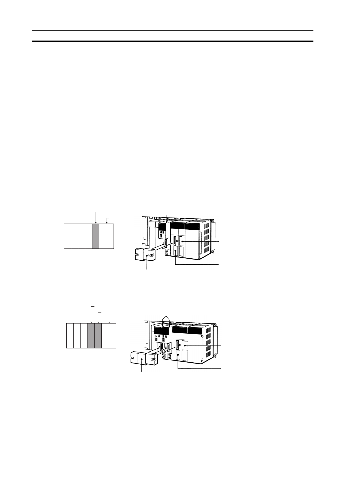
Unit Installation Section 3-2
(
)
2. Be sure that all screws on the Backplane, the Bus Connection Unit, the terminal block, and cables are tightened firmly. If screws work loose, a malfunction may occur as a result of vibration.
3. A label has been placed over the upper surface of the Controller Link Unit
to prevent scraps of wire from entering the Unit. Conduct wiring and installation with this label in place. If wire scraps get into the Unit, it will malfunction.
4. Remove the label after wiring and installing the Controller Link Unit to prevent overheating. Overheating will cause the Unit to malfunction.
3-2-1 Mounting Controller Link Units
C200HX/HG/HE PLCs
Up to two C200HX/HG/HE Controller Link Units can be mounted on the CPU
Rack. Controller Link Units cannot be mounted to an Expansion I/O Rack or a
Slave Rack.
Note Tighten the screws on the Backplane to a torque of 1.2 N • m.
Tighten the screws on the Bus Connection Unit to a torque of 0.4 N • m.
Installing One Controller Link Unit
Mount the Unit in the slot on the left of the CPU Unit.
CPU Backplane
CPU Backplane
Controller Link Unit
CPU Unit
C200HW-CE001 Bus Connection Unit
For one Unit
Installing Two Controller Link Units
Mount the Units in the two slots on the left of the CPU Unit.
Controller Link Unit
Controller Link Unit
CPU Unit
C200HW-CE002 Bus Connection Unit
(For two Units)
C200HW-CLK21
Controller Link Unit
C200HW-CLK21
Controller Link Unit
CPU Unit
(C200HE-CPU32/42-(Z)E
C200HG-CPU33/43/53/63-(Z)E
C200HX-CPU34/44/54/64-(Z)E
C200HW-COM01/04
Communications Board
CPU Unit
(C200HE-CPU32/42-(Z)E
C200HG-CPU33/43/53/63-(Z)E
C200HX-CPU34/44/54/64-(Z)E
C200HW-COM01/04
Communications Board
59

Unit Installation Section 3-2
Installing with Another Communications Unit
When installing a Controller Link Unit along with another Communications
Unit, such as a SYSMAC LINK Unit or a SYSMAC NET LINK Unit mount both
Units in the 2 slots on the left of the CPU Unit.
CPU Backplane
Install the Controller Link
Unit in one slot and the
other Unit in the other slot.
CPU Unit
C200HW-CE002 Bus Connection Unit
(For two Units)
Installing with a PC Card Unit
When installing a Controller Link Unit along with a PC Card Unit, mount the
Controller Link Unit in the first slot on the left of the CPU Unit. Use the
C200HW-CE012 Bus Connection Unit.
PC Card Unit
Controller Link Unit
CPU Unit
Other Communications Unit
C200HW-CLK21
Controller Link Unit
C200HW-PCU01
PC Card Unit
C200HW-CLK21
Controller Link Unit
CPU Unit
(C200HE-CPU32/42-(Z)E
C200HG-CPU33/43/53/63-(Z)E
C200HX-CPU34/44/54/64-(Z)E
C200HW-COM01/04
Communications Board
CPU Unit
(C200HE-CPU32/42-(Z)E
C200HG-CPU33/43/53/63-(Z)E
C200HX-CPU34/44/54/64-(Z)E
CVM1 and CV-series PLCs
Note Tighten the screws on the Backplane to a torque of 1.2 N • m.
C200HW-COM01/04
C200HW-CE012 Bus Connection Unit
Communications Board
Up to four Controller Link Units for CVM1 and CV-series PLCs can be
installed in a CPU Backplane or a Expansion CPU Rack (including both Optical and Wired Units). Controller Link Units cannot be installed on an Expansion I/O Rack, a SYSMAC BUS Slave Rack, or a SYSMAC BUS/2 Slave
Rack.
The CVM1 and CV-series Controller Link Unit is classified as a CPU Bus Unit
and must be mounted in a CPU bus slot.
Tighten the fixed screws on the CPU Unit to a torque of 0.9 N • m.
60

Unit Installation Section 3-2
CPU Backplane
CV500-BC101, CVM1-BC103/CV500-BC051, CVM1-BC053/CV500-BC031
I
O
C
CPU Rack
The Unit can be mounted to the 3/5/10 slots
C
P
shown in the diagram on the right. (It cannot
P
S
be mounted to the leftmost slot even if an
U
Expansion CPU Rack is not used.)
(CV500/CV1000/CV2000/CVM1)
Expansion CPU Rack
CV500/BI111
I
O
I
CPU Backplane
F
2/3/5/8/10 slots
I
O
I
Expansion
F
Backplane
3/5/8/10 slots
CS-series PLCs
3/5/10 slots
CPU
Unit
11 slots
Of these
slots,
installation
is possible
in up to 4
slots.
Install in four of
these 14, 16, or
21 slots.
Expansion CPU Rack
Any of the 11 slots shown in the illustration
P
can be used. The leftmost slot cannot be
S
used.
Expansion I/O Rack
Controller Link Units cannot be mounted to
P
Expansion I/O Racks.
S
PS: Power Supply Unit
CPU: CPU Unit
IOC: I/O Control Unit
IOIF: I/O Interface Unit
Up to a total of four Controller Link Units (wired, optical, and optical ring) for
CS-series PLCs can be installed in a CPU Backplane or a CS Expansion
Rack. Controller Link Units cannot be installed on an C200H Expansion I/O
Rack or a SYSMAC BUS Slave Rack.
Note Tighten the screws on the Backplane to a torque of 0.9 N • m.
Tighten the fixed screws on the CPU Unit to a torque of 0.4 N • m.
CPU Backplane
CS1W-BC103, CS1W-BC083, CS1W-BC053, CS1W-BC033, CS1W-BC023
2/3/5/8/10 slots
CS Expansion Backplane
CS1W-BI108, CS1W-BI083, CS1W-BI053, CS1W-BI033
3/5/8/10 slots
C200H Expansion I/O Backplane
CPU Rack
The Unit can be mounted to the 2/3/5/8/10
slots shown in the diagram on the right.
CS Expansion Backplane
Slots 3/5/8/10 shown in the illustration can be
used.
C200H Expansion I/O Backplane
Controller Link Units cannot be mounted to
Expansion I/O slots.
PS: Power Supply Unit
CPU: CPU Unit
Install in four of
these slots.
61

Unit Installation Section 3-2
Note When installing several CS-series CPU Bus Units at the same time, a total of
16 CS-series CPU Bus Units maximum may be installed.
CJ-series PLCs
Up to a total of four Controller Link Units for CJ-series PLCs can be connected
in a CPU Rack or a Expansion Rack. (Be sure to secure the Units with the top
and bottom sliders.)
CPU Rack
PSC
P
U
CJ-series Expansion
Rack
P
S
CJ-series Expansion
Rack
P
S
CJ-series Expansion
Rack
P
S
I
C
End Cover
10 Unit max.
I
I
End Cover
10 Unit max. Up to 4 Controller Link Unit can
be mounted to these positions.
I
I
End Cover
10 Unit max.
I
I
62
End Cover
10 Unit max.
PS: Power Supply Unit
CPU: CPU Unit
IC: I/O Control Unit
II: I/O Interface Unit
Note When installing several CJ-series CPU Bus Units at the same time, a total of
16 CJ-series CPU Bus Units maximum may be installed.

Unit Installation Section 3-2
CQM1H-series PLCs
Only one Controller Link Unit can be connected in a CQM1H-series PLC.
Connect the Controller Link Unit to the left side of the CPU Unit and then connect the Power Supply Unit to the left of the Controller Link Unit.
After the Units have been connected, secure them with the slide locks on the
top and bottom of the Units.
CQM1H-CLK21
Controller Link Unit
CPU
CPU Backplane
Unit
Power Supply Unit
3/5/10 slots
Expansion CPU
Backplane
Note The CQM1H-CLK21 Controller Link Unit can be connected only to the
CQM1H-CPU51/61 CPU Unit. It cannot be connected to the CQM1H-CPU11/
21 CPU Unit.
3-2-2 Mounting a Repeater Unit
Repeater Units can be either mounted on a DIN Track or screw-mounted.
11 slots
Of these
14, 16, or
21 slots,
installa
tion is
possible
in up to 4
slots.
CQM1H-CPU51/61
CPU Unit
63

Unit Installation Section 3-2
Screw-mounting a Repeater Unit
Use M4 × 15 screws to mount the Unit as shown in the following diagram.
Two, M4
81 mm
Mounting a Repeater Unit on DIN Track
1,2,3... 1. Unlock the DIN Track mounting pins located on the rear of the Repeater
Unit.
2. Attach the Repeater Unit by hooking it onto the DIN Track from above (1)
and then pressing it into place (2).
3. Lock all DIN Track mounting pins.
4. Secure the Repeater Unit by mounting one End Plate on each side of the
Unit. End Plates are attached by hooking first the bottom (1) then the top
of the Plate onto the DIN Track and pulling down (2). Use the screw on the
each End Plate to fasten it in place.
21 mm
8 mm
DIN Track mounting pin
DIN Track
64
Mount the Repeater Unit to DIN Track. Use at least three screws to attach the
DIN Track to the control panel.
DIN Track: PFP-50N (50 cm), PFP-100N (100 cm), PFP-100N2 (100 cm)
The DIN Track should be attached within the control panel using M4 screws
spaced not more than 210 mm (not more than 6 holes) apart. Attach a DIN
Track in at least 3 points for the longest DIN Track length. Tightening torque
should be 1.2 N·m.

Wiring Section 3-3
PFP-100N2
PFP-100N/50N
End Plate: PFP-M (2 Plates required per Repeater Unit)
3-3 Wiring
3-3-1 Communications Cables
Using the specified twisted-pair cable, connect all nodes using the multidrop
method.
Terminating resistance
switch (ON)
Communications Cables
The following shielded twisted-pair cables should be used for Controller Link
Network connections.
Li2Y-FCY2 x 0.56 qmm Kromberg & Schubert,
1 x 2 x AWG
#9207 Belden
ESVC 0.5 x 2 C Bando Densen Co.
ESNC0.5X2C-99-087B Japan Electric Wire & Cable Co.
– 20PE + Tr.CUSN + PVC
Controller Link Unit
Terminating resistance
switch (OFF)
Model Manufacturer
Terminating resistance
switch (OFF)
Komtec Department
Draka Cables Industrial
Terminating resistance
switch (ON)
BD
BD
SHLD
g
H
#
L
Note 1. Use the specified cable only.
2. Keep communications cables separated from power lines or a high-tension
lines to prevent influences from electronic noise.
65

Wiring Section 3-3
3. Do not connect the shield cable of the communications cable to a ground
that is also being used for power-system devices, such as inverters.
4. Ground the shield line of the communications cable at one end of the network. Do not ground the shield at both ends.
5. Do not run wiring outdoors. If outdoor wiring is necessary, take protective
measures against lightning, such as underground wiring or wiring inside
pipes.
6. The minimum length of the communications cable between nodes is 1 m.
Prepare the communications cables at a length of 1 m or more.
7. Use the multidrop method for connecting nodes. Normal communications
will not be possible with T branches.
8. Turn ON the terminating resistance switch at the nodes at both ends of the
network to connect terminating resistance. Turn OFF the terminating resistance switch at all other nodes.
9. A label has been placed over the upper surface of the Controller Link Unit
to prevent scraps of wire from entering the Unit. Conduct wiring and installation with this label in place. If wire scraps get into the Unit, it will malfunction (C200HW-CLK21, CS1W-CLK21-V1, CJ1W-CLK21-V1, and CQM1HCLK21 only).
10. Remove the label after wiring to avoid overheating. Overheating will cause
the Unit to malfunction (C200HW-CLK21, CS1W-CLK21-V1, CJ1WCLK21-V1, and CQM1H-CLK21 only).
Connecting the Shield Line
Terminal Block Connections
Connect both ends of the shield line to the terminal blocks and earth the terminal block at the one end of the network.
g
H
BD
#
L
BD
SHLD
Not Unit a Relay Terminal Block
C200HW-CLK21
(End node)
BD H
BD L
SHLD
Terminating
resistance
(ON)
CVM1-CLK21
Terminating
resistance
(OFF)
TER
SW
Ҵ
ON
BD H
BD L
SHLD
TER SW
Ҵ
ON
Terminating
resistance
(ON)
CS1W-CLK21-V1
CJ1W-CLK21-V1
(End node)
Ҵ
TER SW
ON
BD H
BD L
SHLD
66
Ground
Note Use the recommended crimp terminals when connecting the cable’s signal
lines or shield line to the terminal blocks. Short circuits can damage the Units.

Wiring Section 3-3
Using a Relay Terminal Block
Ground
CVM1-CLK21
C200HW-CLK21
(End node)
BD H
BD L
SHLD
Terminating
resistance
(ON)
Relay
Terminal
Block (see
note 1.)
TER
SW
Ҵ
ON
Terminating
resistance
(OFF)
BD H
BD L
SHLD
TER SW
Ҵ
ON
Terminating
resistance
(ON)
Note 1. Mounting and dismounting during communications is not possible for Re-
lay Terminal Blocks connected to the nodes at the ends of the network (i.e.:
the nodes with terminating resistance).
2. Use the recommended crimp terminals when connecting the cable’s signal
lines or shield line to the terminal blocks. Short circuits can damage the
Units.
CS1W-CLK21-V1
CJ1W-CLK21-V1
(End node)
Ҵ
TER SW
ON
BD H
BD L
SHLD
Connecting the Communications Cables
Use crimp terminals when connecting communications cables to a Controller
Link Unit. Use the following procedure to connect communications cables to a
terminal block.
1,2,3... 1. Peel back the cover of the cable for about 50 mm without scratching the
mesh of the shield. Do not peel too much because it may cause a shortcircuit.
2. Twist the mesh of the shield to form a line.
3. Leave the tip of the wire created by twisting the shield exposed and cover
the remaining section with a heat-shrinking tube.
Cover with a
heat-shrinking
tube
Approx. 50 mm
Wire created by
twisting the shield
Exposed portion for
crimp terminal
connection
4. Remove enough of the cover from the signal lines to allow the crimp terminals to be connected, taking care not to damage the signal lines. Damage
to the signal lines could cause the cable to break.
67

Wiring Section 3-3
5. Twist firmly the portion of the signal lines that are exposed.
6. Apply vinyl tape or heat-shrinking tube to the end of the cover that was
peeled in step 1.
Apply vinyl tape or a
heat-shrinking tube.
7. Mount the crimp terminal onto the signal lines and the shield line. Use M3
crimp terminals.
8. Connect the signal lines and the shield line to the terminal block using the
markings on the terminal block.
Communications cable
from the previous node
Shield line
Communications cable
to the next node
Communications data
High signal
Communications data
Low signal
Note a) You can change the length of the signal lines as shown in the fol-
lowing diagrams to make wiring a lot easier.
Approx. 30 mm
Approx. 40 mm
Approx. 50 mm
68

Wiring Section 3-3
b) The approximate dimension for when the cable has been wired
from the terminal block along the front of the Unit is shown in the
following diagram.
25 mm max.
Note 1. Always turn OFF the power to the PLC before connecting the communica-
tions cables.
2. Always use a crimp terminal for wiring. If a wire that has only been twisted
is connected directly to a terminal block, short circuit, malfunction and
product damage will result.
3. Use the recommended crimp terminals.
4. When mounting the crimp terminal, always use the appropriate tools for
each crimp terminal and follow the appropriate installation procedures.
Contact the crimp terminal manufacturer for details on the appropriate
tools and procedures. Failure to use the appropriate tools and procedures
could cause cables to break.
5. Measure the length of peeled cable during installation according to the
crimp terminal used and make sure that the peeled length is not too long.
Cover the compressed section of the crimp terminal and cable with vinyl
tape or heat-shrinking tube.
6. Be sure not to confuse the signal lines and shield line connections.
7. Tighten the screws on the terminal block firmly. The correct tightening
torque is 0.5 N·m.
8. If a signal line disconnects from the terminal, either the Unit will be unable
to communicate with other nodes on the network or that section of the network will be isolated from other nodes. Be sure not to pull on the signal
lines.
Controller Link Unit
Isolated
(Transmission not possible)
9. Do not pull on a communication cable.
Transmission
not possible
69

Wiring Section 3-3
10. When bending a communications cable, allow 60 mm or more for the bending radius (R).
11. Do not place any object on the communications cable.
12. Supply power only after checking the wiring thoroughly.
13. Connect the terminal block only after checking it thoroughly.
14. Marks are provided on the terminal block for the signal lines. Connect the
signal lines according to the marks. The marks correspond to signal lines
as listed below.
Mark Signal name Line color
g
@
None SHLD (shield) ---
BDH (communications data high) Black
BDL (communications data low) White
3-3-2 Repeater Units
Power Supply Wiring
Repeater Units must be supplied with DC power. The procedure for wiring the
power supply is the same for all Repeater Units (CS1W-RPT01/02/03).
Use the following procedure to wire the power supply to Repeater Units.
1,2,3... 1. Attach the following crimp terminal to each of the two power lines.
Crimp terminal: AI Series manufactured by Phoenix Contact
Crimp terminal Cable
Insert the cable and then crimp the terminal.
The following specialized tool is available for this purpose:
ZA3 manufactured by Phoenix Contact
2. Insert the crimp terminals on the positive and negative power lines into the
orange power connectors located near the bottom of the front panel of the
Repeater Unit. Insert the positive line in the top and the negative line in the
bottom.
3. Use a small, flat-blade screwdriver to fasten the crimp terminals in place.
Note 1. Supply power to the Repeater Unit using a power supply installed specifi-
cally for the Repeater Unit. Do not supply power to the Repeater Unit from
an I/O power supply, motor power supply, or control power supply.
2. To prevent the power supply from being affected by noise, wire and install
the power supply away from power lines and high-voltage lines.
3. Attach special-purpose crimp terminals to the power cables.
4. Do not connect the positive and negative lines to the wrong connectors.
5. The power cable screws should be fastened to a tightening torque of
0.2 N·m.
6. Do not pull on the power cable.
7. Do not bend the power cable past its natural bending radius.
70
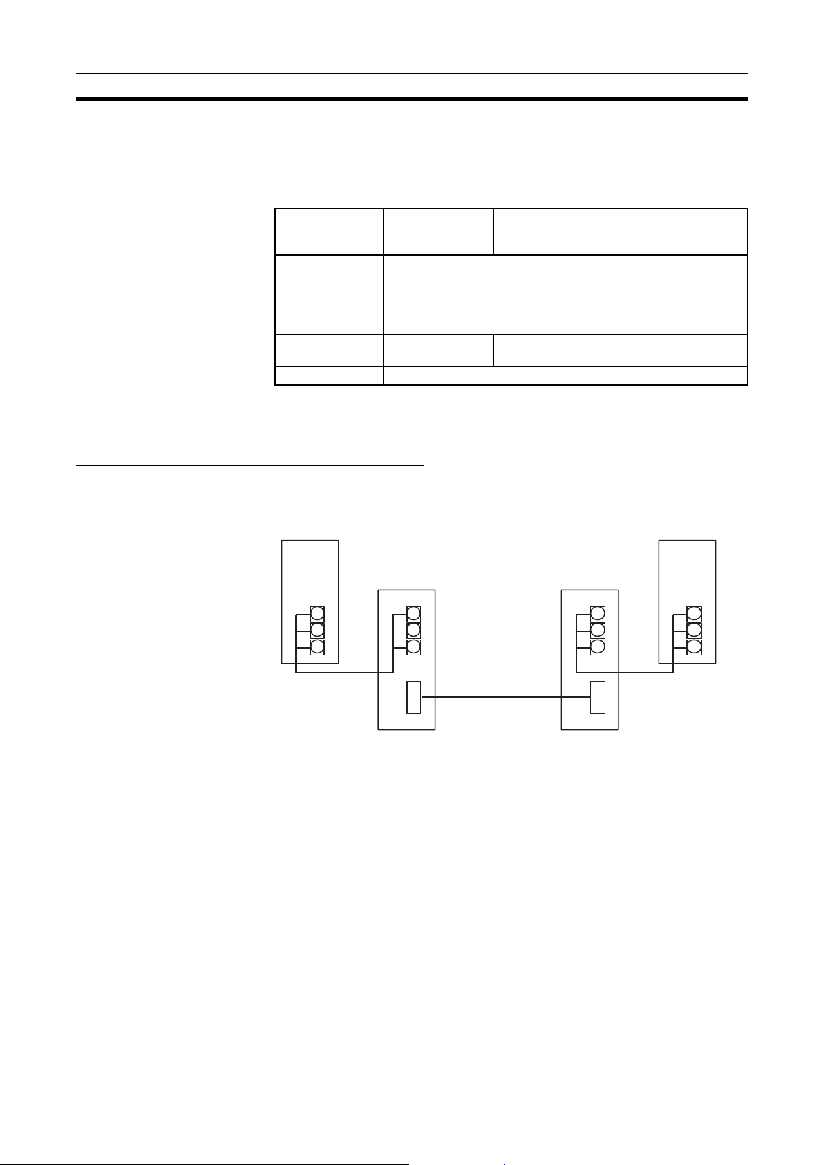
Wiring Section 3-3
8. Do not place any object on the power cable.
9. Check that connectors are correctly attached before using the Unit.
Power Supply Specifications
The power supply to the Repeater Unit must meet the following specifications.
Item CS1W-RPT01
Power supply voltage
Allowable power
supply voltage
range
Current consumption
Inrush current 2.5 A max. (24 V DC with rise time 5 ms)
Wire-to-Wire
Repeater Unit
24 V DC
20.4 to 26.4 V DC (24 V DC, −15% to 10%)
24 V DC at 60 mA
max.
The following Power Supply Unit is recommended:
OMRON S82K Series
CS1W-RPT02
Wire-to-Optical (H-
PCF) Repeater Unit
24 V DC at 60 mA
max.
CS1W-RPT03
Wire-to-Optical (GI)
Repeater Unit
24 V DC at 70 mA
max.
Laying Optical Cable (CS1W-RPT02/03 Only)
Optical fiber cable (H-PCF or GI) can be used to create an optical connection
in part of a wired network.
CS1W-RPT02 (H-PCF)
Wired Controller
Link Unit
CS1W-RPT02
Repeater Unit
SL1
H-PCF cable
SL2
SL1
Wired Controller
Link Unit
SL2
CS1W-RPT02
Repeater Unit
Note 1. Always use the specified Optical Fiber Cables.
2. The maximum distance between nodes depends on how the cable is connected. For details, refer to the applicable Optical Fiber Cable (H-PCF)
manual.
Connection Procedure Use the following procedure to connect Optical Fiber Cables to a Unit.
1,2,3... 1. Tighten screws in the mounting brackets so that the through-holes on the
terminal are on the top and bottom and then affix hexagonal nuts from the
opposite side of the terminal.
2. Insert bushing to the mounting bracket and secure the Unit with screws.
3. Pass the tension member through the through-holes, and tighten the terminal screws to affix the tension member.
4. Affix the cable to the mounting bracket so that it is clamped by the bracket.
71

Wiring Section 3-3
5. Move the cable connector so that the loose ends are on the left-hand side,
and insert the Unit’s optical connector as far as it will reach.
Example: Connections for Duplex Operation of Communications Units
Mounting bracket
Tension member
Terminal
CS1W-RPT02
P
W
R
T
/
R
1
T
/
R
2
B
D
H
B
D
L
S
L
1
S
H
L
D
T
E
R
S
W
O
N
O
N
S
W
1
1
B
A
U
D
2
R
A
T
E
S
L
2
+
D
C
2
4
V
IN
P
U
T
−
• Insert the connectors completely and always check that the connectors
are locked before starting operation.
Even in token-ring mode, the network will be broken and communications may
be disrupted if disconnections occur at two or more places. Be sure not to
allow connectors to be disconnected during communications.
• Do not pull on the Optical Fiber Cable too forcefully.
The maximum tension that can be applied to the cord is 10 kg and the
maximum tension that can be applied to the cable is 50 kg.
Cord
Cable
• Do not bend the cable too sharply. The minimum radius for bends is
10 cm.
• To prevent the Optical Fiber Cable from being pulled too forcefully, always
use the cable securing bracket and provide space below the Unit as
shown in the following diagram. Do not exceed the maximum tension for
the cord and cable:
Cord: 0 kg (Do not apply any tension.)
Cable: 5 kg
Cord Cable
• Do not place objects on top of the Optical Fiber Cable. The maximum
pressure that can be placed on the cord and cable is as follows:
Cord: 30 kg/10 cm
Cable: 50 kg/10 cm
• Inspect the connector before installing it.
72

Wiring Section 3-3
Communications Cables
Optical Bus or Optical
Ring System (H-PCF
Cable)
The following devices are required for the Optical Bus or Optical Ring (H-PCF)
Controller Link Network. The cable and connectors are the same as those
used for Optical SYSMAC LINK Networks.
Optical Fiber Cables (Indoor Use Only)
Use the following Optical Fiber Cables (Hard Plastic-clad Fiber: H-PCF).
Name Specifications Model
H-PCF cables Black 10 m S3200-HCCB101
50 m S3200-HCCB501
100 m S3200-HCCB102
500 m S3200-HCCB502
1,000 m S3200-HCCB103
Orange 10 m S3200-HCCO101
50 m S3200-HCCO501
100 m S3200-HCCO102
500 m S3200-HCCO502
1,000 m S3200-HCCO103
Note The Optical Fiber Cable model numbers are as follows.
S3200-H@@@@@@@
Tensioner option
None: Standard (with tension member)
N: Without tension member
Cable length
@@@
A B
(A/10) x 10
Cable color
B: Black
O: Orange
Cable specification
L: With power supply line
C: Without power supply line
Type
B: Cord
C: Cable
Name Model Specifications
Connector S3200-COCF2011 Use to connect a cable to a node.
(Full-lock connector for crimp-cut cable.)
S3200-COCF2511 Use to connect a cable to a node.
(Half-lock connector for crimp-cut cable.)
Inline Adapter S3200-COIAT2000 Use to connect or extend cables.
(Use one adapter for each connection.)
B
m
Note 1. Either full-lock or half-lock connectors can be used in a Controller Link Net-
work, but we recommend full-lock connectors to prevent accidental disconnections during operation.
2. The maximum distance between nodes is slightly shorter for connectors
with crimp-cut cables compared to connectors assembled with adhesive.
Also, the maximum distance is reduced due to extension loss when Inline
Adapters are used to extend cables.
73

Wiring Section 3-3
Optical Fiber Cables with Connectors (Indoor Use Only)
The following Optical Fiber Cables are available with Connectors already
attached.
Specifications Length Model
Optical Fiber Cable Connectors:
S3200-COCF2011
ß
S3200-COCF2011
Optical Fiber Cable Connectors:
S3200-COCF2011
ß
S3200-COCF2511
Optical Fiber Cable Connectors:
S3200-COCF2511
ß
S3200-COCF2511
2 m S3200-CN201-20-20
5 m S3200-CN501-20-20
10 m S3200-CN102-20-20
15 m S3200-CN152-20-20
20 m S3200-CN202-20-20
Over 20 m S3200-CN-20-20
(Specify length (m) when ordering.)
2 m S3200-CN201-20-25
5 m S3200-CN501-20-25
10 m S3200-CN102-20-25
15 m S3200-CN152-20-25
20 m S3200-CN202-20-25
Over 20 m S3200-CN-20-25
(Specify length (m) when ordering.)
2 m S3200-CN201-25-25
5 m S3200-CN501-25-25
10 m S3200-CN102-25-25
15 m S3200-CN152-25-25
20 m S3200-CN202-25-25
Over 20 m S3200-CN-25-25
(Specify length (m) when ordering.)
Note 1. Consult a specialist tradesman if cables with outdoor specifications are re-
quired.
2. The cables listed above are black and have power supply lines and tension
members, although the power supply lines aren’t used in the Controller
Link Network.
3. All of the cables listed above are attached to the connectors with adhesive.
4. Special training is required to assemble Optical Fiber Cables and connectors with adhesive.
Optical Fiber Cable Accessories
Use the following accessories to assemble and test Optical Fiber Cables.
Name Model Specifications
Optical Fiber Assembly Tool
Optical Power Tester S3200-CAT2700 With S3200-CAT2702 Head Unit and
Master Fiber Set S3200-CAT2001H One meter cable for use with the
S3200-CAK1062 Crimp-cut tool for the S3200-
COCF2011/2511 Connectors
adapter for the S3200-COCF2011/
2511 Connectors
S3200-CAT2702 Head Unit
This manual does not provide details on Optical Fiber Cable preparation. For
details, refer to the instructions provided with the S3200-CAK1062 Assembly
Tool.
74

Wiring Section 3-3
CS1W-RPT03 (GI)
Wired Controller
Link Unit
CS1W-RPT03
Repeater Unit
SL1
Receive
Send
SL2
GI cable
Receive
Send
CS1W-RPT03
Repeater Unit
SL1
Wired Controller
Link Unit
SL2
Note 1. Always use the specified Optical Fiber Cables.
2. Although the Optical Fiber Cables can be distinguished by the markings or
color, in order to prevent incorrect connection it is recommended that tags
are attached to the cables.
3. The maximum distance between nodes depends on the type of GI cable
(core diameter) that is being used.
62.5/125
50/125
µm cable: Max. distance between nodes = 2 km
µm cable: Max. distance between nodes = 1 km
Connection Procedure Use the following procedure to connect Optical Fiber Cables to a Unit.
1,2,3... 1. Attach the mounting bracket to the Unit with the provided screws.
2. Attach the clamp to the mounting bracket so that it clamps the cable(s).
1. Screw the mounting
bracket to the Unit.
Mounting bracket
2. Attach the clamp to the
mounting bracket so that
the cable(s) are clamped.
Clamp
3. Remove the Optical Connector Covers from the Unit’s connectors shown
in the following diagram if there are covers protecting the connectors.
75

Wiring Section 3-3
Remove the covers from the tips of the cables’ ST connectors if there are
covers protecting the ST connectors.
Optical Connector Cover
Rotate the cover 90°
counterclockwise.
Pull off the cover.
Note To replace the Optical Connector Cover, just reverse the steps shown
in the diagram above.
4. Turn the cable connector so that the tab in the connector faces left and
aligns with the slot in the Unit’s connector. Insert the cable connector fully
into the Unit’s optical connector. Press and turn the cable’s connector
clockwise to lock the connector in place.
Ta b
Cable
connector
Press and turn the metal fitting on
the cable connector until it locks.
Unit's optical
connector
Slot
Align the tab in the cable connector with
the slot in the Unit's connector and fully
insert the cable connector.
Note To remove the connector, just reverse the steps shown in the diagram
above. (Press and turn the cable connector’s metal fitting counterclockwise to unlock the connector.)
5. After installing the Optical Fiber Cable, fix the tension member of the Optical Fiber Cable.
Insert the connectors completely and always check that the connectors are
locked before starting operation.
When installing Optical Fiber Cables, be sure to stay within the specifications
(e.g., tensile strength, bending, lateral pressure) for the cables used.
Optical Fiber Cables
Use Optical Fiber Cables (Graded Index: GI) with the following optical specifications.
50/125
Item Minimum Standard Maximum Unit Conditions
Numerical Aperture (N.A.)
Transmission
loss
Connection loss --- --- 1.0 λ = 0.8 µm, one location
Transmission
bandwidth
--- 0.21 --- --- Theoretical value
--- --- 3.0 Lf dB 0.5 km ≤ Lf λ = 0.8 µm
500 --- --- MHz⋅km λ = 0.85 µm (LD)
µm AGF Cable
3.0 Lf + 0.2 0.2 km ≤ Lf < 0.5 km
3.0 Lf + 0.4 Lf < 0.2 km
76
T
= 25°C
a

Constructing Networks with Repeater Units Section 3-4
Note Lf is fiber length in km, Ta is ambient temperature, and λ is the peak wave-
length of the test light source.
62.5/125
Item Minimum Standard Maximum Unit Conditions
Numerical Aperture (N.A.)
Transmission
loss
Connection loss --- --- 1.0 λ = 0.8 µm, one location
Transmission
bandwidth
--- 0.28 --- --- Theoretical value
--- --- 3.5 Lf dB 0.5 km ≤ Lf λ = 0.8 µm
200 --- MHz⋅km λ = 0.85 µm (LD)
Note L
is fiber length in km, Ta is ambient temperature, and λ is the peak wave-
f
µm AGF Cable
3.5 Lf + 0.2 0.2 km ≤ Lf < 0.5 km
3.5 Lf + 0.4 Lf < 0.2 km
length of the test light source.
Connectors
ST Connector
3-4 Constructing Networks with Repeater Units
Repeater Units can be used to construct flexible networks such as those
shown below.
T-Branch Wiring
Long-distance Wiring
500 m max.
(at 2 Mbit/s)
T
= 25°C
a
CS1W-RPT01
Repeater Unit
62-node Configuration
31 nodes max.
CS1W-RPT01
Repeater Unit
CS1W-RPT01
31 nodes max.
Repeater Unit
Partial Conversion to Optical Cable
Wire cable Wire cable
CS1W-RPT02/03
Repeater Unit
500 m max.
(at 2 Mbit/s)
Optical cable
Note 1. Repeater Units must be supplied with 24-V DC power.
2. Wire-to-Optical Repeater Units (CS1W-RPT02 and CS1W-RPT03) are
used to convert a section of a wired network to optical fiber. Two Units are
always used as a single set.
Wire-to-Optical Repeater Units cannot be connected to Optical Ring/Optical Controller Link Units or Support Boards. If these types of Controller
Link Units or Support Boards are connected by mistake, communications
errors will occur throughout the network.
3. Repeater Units have a baud rate switch and a terminating resistance
switch. The same baud rate must be set for all nodes on the network.
In addition, the terminating resistance switch of Units (Controller Link
CS1W-RPT02/03
Repeater Unit
77
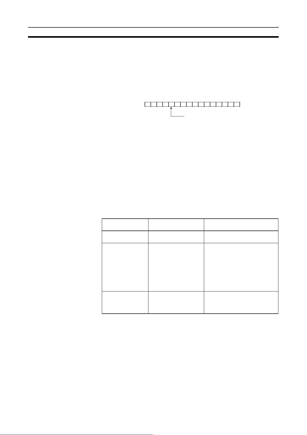
Constructing Networks with Repeater Units Section 3-4
Units/Support Boards or Repeater Units) at both ends of each network
segment created by installing Repeaters must also be turned ON.
To construct a 62-node configuration in a wired network, all network nodes
must consist of one of the following models:
CS1W-CLK21-V1, CJ1W-CLK21-V1, 3G8F7-CLK21-V1
The following Wired Network 62 Node Enable Bit in the DM Parameter
Area software switch on each node must be turned ON to enable using 62
nodes maximum:
Software switch
(D30000+100 ×
unit number)
15 14 13 12 11 10 9 8 7 6 5 4 3 2 1 0
−−−− −−−−−−−−−−
Wired Network 62 Nodes Enable Bit
0: 32 nodes max.
1: 62 nodes max.
−
4. Repeater Units can be connected in a network in advance if new nodes are
to be added to the network after the system has been constructed. When
it becomes necessary to add a node, cabling can be accomplished easily
by simply wiring a T-Branch to the Repeater Unit. This method also allows
nodes to be added without stopping communications over the existing network.
3-4-1 Segments
Repeater Units divide a wired Controller Link network into segments. Segments are comprised of nodes connected in a multi-drop configuration using
wire cables. The specifications of the network within a segment are identical
to the wired Controller Link network itself. The specifications within a single
segment are shown in the following table.
Item Specifications within
Transmission line
type
Baud rate and maximum transmission
distance
Maximum number of
nodes (Units)
each segment
Multi-drop ---
2 Mbps: 500 m
1 Mbps: 800 m
500 Kbps: 1 km
32, including Controller
Link Units, Support
Boards, and Repeater
Units
Because Repeater Units enable
up to 2 stages to be connected,
the maximum transmission distance of a network (i.e., the total
length of the longest path connecting any two nodes) is as follows:
Repeater Units do not use a node
address.
2 Mbps: 1.5 km
1 Mbps: 2.4 km
500 Kbps: 3 km
Remarks
78

Constructing Networks with Repeater Units Section 3-4
Wire
3-4-2 Number of Repeater Units
The number of Repeater Units that can be connected in a Wired Controller
Link Network depends on the mode of connection.
When Repeater Units are used, a maximum of 32 Units, including Controller
Link Units/Support Boards and Repeater Units, can be connected within a
single segment.
Moreover, if Repeater Units are used for T-Branch wiring, long-distance wiring
or partial conversion to optical fiber, up to two repeater stages (see note
below) can be connected. Connect Repeater Units so that they do not exceed
these ranges.
Optical
fiber
cable
: Controller Link Unit/Support
Board
: Wire-to-wire Repeater Unit
: Wire-to-optical Repeater Unit
(two Units used in a pair)
: Range of a single segment
Note: The Repeater Unit will be
counted in the number of
nodes for each segment that
it is connected to.
Note The maximum number of repeater stages refers to the maximum number of
Repeater Units that can be inserted into the path connecting any two nodes.
In other words, it is necessary to connect Repeater Units so that no more than
two Repeater Units (two stages) need to be passed for any node within a network to reach any other node. With Wire-to-Optical Repeater Units, two Units
make up a single set, which is counted as a single stage.
Examples of Correct Repeater Unit Connections
T-Branch Wiring: 2-stage Repeater Unit Connection
Stage 1
Not more than 2 Repeater Units (2 stages) must be passed for any node to
reach any other node
Stage 2
CS1W-RPT01
Repeater Unit
79

Constructing Networks with Repeater Units Section 3-4
Long-distance Wiring: 2-stage Repeater Unit Connection
Stage 2
CS1W-RPT01
Repeater Unit
Not more than 2 Repeater Units (2 stages) must be passed for any node to
reach any other node
Partial Optical Conversion: 2-stage Repeater Unit Connection
Stage 1 Stage 2
Optical
fiber cable
Two Wire-to-Optical Repeater Units make up a single set counted as a single
stage. Therefore, not more than 4 Repeater Units (2 stages) must be passed
for any node to reach any other node.
Examples of Incorrect Repeater Unit Connections
More than 2 Stages of Repeater Units
CS1W-RPT02 or
CS1W-RPT03
Repeater Unit
PLC A
PLC B
CS1W-RPT01
Repeater Unit
The path from PLC A to PLC B travels via 3 Repeater Units (3 stages). This
kind of network is NOT allowed.
More than 2 Stages of Repeater Units
80
CS1W-RPT01
Repeater Unit

Constructing Networks with Repeater Units Section 3-4
The path from one node to another travels via three Repeater Units
(3 stages). This kind of network is NOT allowed.
Note If the Repeater Units are used incorrectly, communications errors may occur,
or nodes may not be able to participate in the network.
3-4-3 Terminating Resistance
In a Wired Controller Link Network, turn ON the terminating resistance
switches only at the nodes at both ends of the network.
When Repeater Units are used to divide the network into multiple segments,
turn ON the terminating resistance switches of the nodes at both ends of each
segment. When a Repeater Unit is connected to the end of a segment, turn
ON the built-in terminating resistance switch of the Repeater Unit itself.
Connection examples are shown below.
T-B r an ch W ir in g
Segment 1
Terminating
resistance: ON
Terminating
resistance: ON
Long-distance Wiring
Terminating
resistance: ON
Terminating
resistance: ON
Terminating
resistance: ON
Terminating resistance is turned ON at both ends of
each segment. (Repeater Units are also equipped
with a built-in terminating resistance switch.)
Terminating
resistance: ON
Segment 1 Segment 2 Segment 3
Terminating
resistance: ON
Segment 2 Segment 3
Terminating
resistance: ON
Terminating
resistance: ON
Terminating
resistance: ON
Terminating
resistance: ON
CS1W-RPT01
Repeater Unit
CS1W-RPT01
Repeater Unit
Terminating
resistance: ON
81

Constructing Networks with Repeater Units Section 3-4
Partial Conversion to Optical Fiber
Terminating
Resistance: ON
Terminating
Resistance: ON
Segment 1 Segment 2
(Optical fiber cable)
Terminating
Resistance: ON
Terminating
Resistance: ON
Repeater Unit
CS1W-RPT02 or
CS1W-RPT03
Combining T-Branch Wiring (2-stage Repeater) and Partial Optical Fiber
Terminating
resistance: ON
Terminating
Segment 1
Terminating
resistance: ON
Terminating
resistance: ON
resistance: ON
Segment 3
Terminating
resistance: ON
CS1W-RPT01
Repeater Unit
CS1W-RPT02 or
CS1W-RPT03
Repeater Unit
Terminating
resistance: ON
Segment 2
Terminating
resistance: ON
Segment 4
Terminating
resistance: ON
Note When constructing a network using Repeater Units, each segment must sat-
isfy all of the following requirements:
• The total number of Controller Link Units, Support Boards, and Repeater
Units within a single segment must not exceed 32.
• The total cable length of a single segment must not exceed the specified
value. (500 m at 2 Mbps; 800 m at 1 Mbps; and 1 km at 500 Kbps.)
• The maximum number of repeater stages that can be inserted into the
path connecting any two nodes is two.
• The node at each end of a segment (including Repeater Units) must have
terminating resistance turned ON.
• The baud rates within each segment must be set to the same value.
82

SECTION 4
Preparations for Communications
This section describes the settings required for starting communications. These basic settings are required for both data
links function and the message service. Carry out the settings described here before turning on power to the Controller Link
Unit.
4-1 CS-series Controller Link Units . . . . . . . . . . . . . . . . . . . . . . . . . . . . . . . . . . . 84
4-1-1 Overview. . . . . . . . . . . . . . . . . . . . . . . . . . . . . . . . . . . . . . . . . . . . . . 84
4-1-2 Unit Number . . . . . . . . . . . . . . . . . . . . . . . . . . . . . . . . . . . . . . . . . . . 84
4-1-3 Node Addresses . . . . . . . . . . . . . . . . . . . . . . . . . . . . . . . . . . . . . . . . 85
4-1-4 Baud Rates . . . . . . . . . . . . . . . . . . . . . . . . . . . . . . . . . . . . . . . . . . . . 86
4-1-5 Terminating Resistance. . . . . . . . . . . . . . . . . . . . . . . . . . . . . . . . . . . 87
4-2 CJ-series Controller Link Units . . . . . . . . . . . . . . . . . . . . . . . . . . . . . . . . . . . 87
4-2-1 Overview. . . . . . . . . . . . . . . . . . . . . . . . . . . . . . . . . . . . . . . . . . . . . . 88
4-2-2 Unit Number . . . . . . . . . . . . . . . . . . . . . . . . . . . . . . . . . . . . . . . . . . . 88
4-2-3 Node Addresses . . . . . . . . . . . . . . . . . . . . . . . . . . . . . . . . . . . . . . . . 89
4-2-4 Baud Rates . . . . . . . . . . . . . . . . . . . . . . . . . . . . . . . . . . . . . . . . . . . . 90
4-2-5 Terminating Resistance. . . . . . . . . . . . . . . . . . . . . . . . . . . . . . . . . . . 90
4-3 C200HX/HG/HE Controller Link Units . . . . . . . . . . . . . . . . . . . . . . . . . . . . . 91
4-3-1 Overview. . . . . . . . . . . . . . . . . . . . . . . . . . . . . . . . . . . . . . . . . . . . . . 92
4-3-2 Node Addresses . . . . . . . . . . . . . . . . . . . . . . . . . . . . . . . . . . . . . . . . 92
4-3-3 Baud Rates and Operating Levels. . . . . . . . . . . . . . . . . . . . . . . . . . . 93
4-3-4 Terminating Resistance. . . . . . . . . . . . . . . . . . . . . . . . . . . . . . . . . . . 94
4-4 CVM1 and CV-series Controller Link Units. . . . . . . . . . . . . . . . . . . . . . . . . . 95
4-4-1 Overview. . . . . . . . . . . . . . . . . . . . . . . . . . . . . . . . . . . . . . . . . . . . . . 95
4-4-2 Unit Number . . . . . . . . . . . . . . . . . . . . . . . . . . . . . . . . . . . . . . . . . . . 96
4-4-3 Node Addresses . . . . . . . . . . . . . . . . . . . . . . . . . . . . . . . . . . . . . . . . 96
4-4-4 Baud Rates . . . . . . . . . . . . . . . . . . . . . . . . . . . . . . . . . . . . . . . . . . . . 97
4-4-5 Terminating Resistance. . . . . . . . . . . . . . . . . . . . . . . . . . . . . . . . . . . 97
4-5 CQM1H-series Controller Link Units. . . . . . . . . . . . . . . . . . . . . . . . . . . . . . . 98
4-5-1 Overview. . . . . . . . . . . . . . . . . . . . . . . . . . . . . . . . . . . . . . . . . . . . . . 98
4-5-2 Node Addresses . . . . . . . . . . . . . . . . . . . . . . . . . . . . . . . . . . . . . . . . 99
4-5-3 Baud Rates . . . . . . . . . . . . . . . . . . . . . . . . . . . . . . . . . . . . . . . . . . . . 99
4-5-4 Terminating Resistance. . . . . . . . . . . . . . . . . . . . . . . . . . . . . . . . . . . 100
4-6 Repeater Units. . . . . . . . . . . . . . . . . . . . . . . . . . . . . . . . . . . . . . . . . . . . . . . . . 100
4-6-1 Wire-to-Wire Repeater Unit . . . . . . . . . . . . . . . . . . . . . . . . . . . . . . . 101
4-6-2 Baud Rates . . . . . . . . . . . . . . . . . . . . . . . . . . . . . . . . . . . . . . . . . . . . 101
4-6-3 Terminating Resistance. . . . . . . . . . . . . . . . . . . . . . . . . . . . . . . . . . . 102
83
 Loading...