

Page 1

Cat. No. W376-E1-06
SYSMAC
CS1W-NC113/213/413/133/233/433
Position Control Units
OPERATION MANUAL
Page 2

CS1W-NC113/213/413/133/233/433 Position Control Units
Operation Manual
Revised February 2008
Page 3

iv
Page 4

Notice:
r
f
OMRON products are manufactured for use according to proper procedures by a qualified operator
and only for the purposes described in this manual.
The following conventions are used to indicate and classify precautions in this manual. Always heed
the information provided with them. Failure to heed precautions can result in injury to people or damage to property.
!DANGER Indicates an imminently hazardous situation which, if not avoided, will result in death or
serious injury. Additionally, there may be severe property damage.
!WARNING Indicates a potentially hazardous situation which, if not avoided, could result in death or
serious injury. Additionally, there may be severe property damage.
!Caution Indicates a potentially hazardous situation which, if not avoided, may result in minor or
moderate injury, or property damage.
OMRON Product References
All OMRON products are capitalized in this manual. The word “Unit” is also capitalized when it refers to
an OMRON product, regardless of whether or not it appears in the proper name of the product.
The abbreviation “Ch,” which appears in some displays and on some OMRON products, often means
“word” and is abbreviated “Wd” in documentation in this sense.
The abbreviation “PLC” means Programmable Controller. “PC” is used, however, in some Programming Device displays to mean Programmable Controller.
Visual Aids
The following headings appear in the left column of the manual to help you locate different types of
information.
OMRON, 2000
All rights reserved. No part of this publication may be reproduced, stored in a retrieval system, or transmitted, in any form, o
by any means, mechanical, electronic, photocopying, recording, or otherwise, without the prior written permission o
OMRON.
No patent liability is assumed with respect to the use of the information contained herein. Moreover, because OMRON is constantly striving to improve its high-quality products, the information contained in this manual is subject to change without
notice. Every precaution has been taken in the preparation of this manual. Nevertheless, OMRON assumes no responsibility
for errors or omissions. Neither is any liability assumed for damages resulting from the use of the information contained in
this publication.
Note Indicates information of particular interest for efficient and convenient opera-
tion of the product.
1,2,3... 1. Indicates lists of one sort or another, such as procedures, checklists, etc.
v
Page 5
Unit Versions of CS-series Position Control Units
9
8
7
6
5
4
3
2
1
0
9
8
7
6
5
4
3
2
1
0
Unit Versions A “Unit version” has been introduced to manage Position Control Units in the
CS Series according to differences in functionality accompanying Unit
upgrades.
Notation of Unit Versions
on Products
CS-series Position Control Unit
NC113
CS
R
U
N
E
R
C
E
R
H
S
E
N
S
D
A
T
A
X
MACH
No.
1
X
10
0
X
10
1
1
24
24
Confirming Unit Versions
with Support Software
1,2,3... 1. In the IO Table Window, right-click the Position Control Unit and select Unit
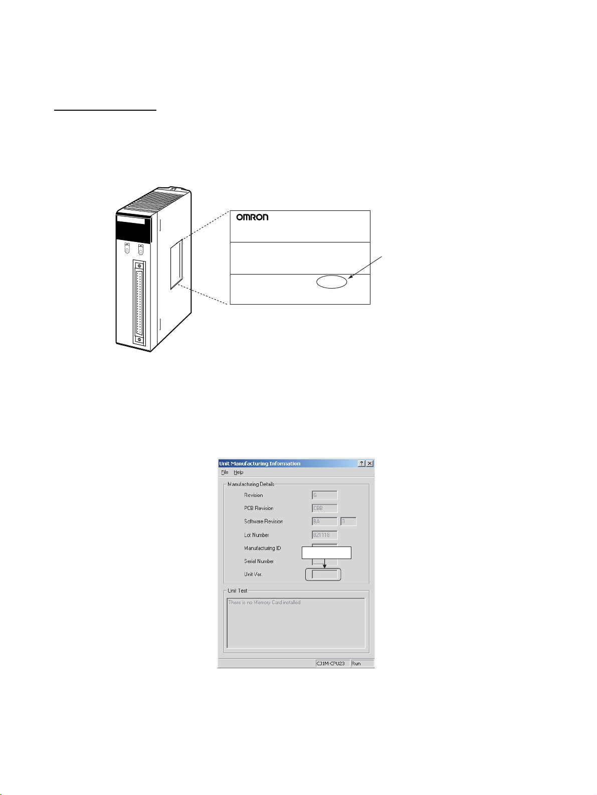
The Unit version is given to the right of the lot number on the nameplate of the
applicable Position Control Units, as shown below.
Product nameplate
CS1W-NC113
NC UNIT
Unit version
Example for Unit version 2.3
Lot No. 031001 0000 Ver.2.3
OMRON Corporation MADE IN JAPAN
The Unit version of the Position Control Units begins at version 2.0.
The Unit version can be confirmed in Unit Manufacturing Information of CXProgrammer version 4.0 or higher using the following procedure.
Manufacturing information.
2. The following Unit Manufacturing information Dialog Box will be displayed.
Unit version
2.3
Example: Unit version 2.3 will be displayed in the Unit Manufacturing
information Dialog Box.
Use the above display to confirm the Unit version of the Position Control
Unit.
vi
Page 6

Using the Unit Version
Label
The following Unit version label is provided with the Position Control Unit.
This label can be attached to the front of the Position Control Unit to differentiate between Position Control Units of different Unit versions.
Unit Version Notation
In this manual, the Unit version of a Position Control Unit is given as shown in
the following table.
Product nameplate Notation used in this manual Special remarks
Ver. 2.0 or later number
shown to the right of the
lot number
Blank to the right of lot
number
CS-series Position Control Unit Ver. 2.0 or later Information without refer-
ence to specific Unit versions applies to all versions
Pre-Ver. 2.0 CS-series Position Control Unit
of the Unit.
Functions Supported by Each Unit Version of Position Control Unit
Unit Version Pre-Ver. 2.0 Ver. 2.0 Ver. 2.1 Ver. 2.2 Ver. 2.3
Internal system software version
CS-series Position Control Units CS1W-NC113/133/213/233/413/433
Functions
Support Software CX-Position Ver.
Changing the acceleration for a multiple
start during relative
movement or absolute movement in
direct operation
Changing acceleration/deceleration time
during jog operation
Setting acceleration/deceleration time
for axis parameters
until the target speed
is reached
Easy backup function Not supported Supported Supported Supported Supported
Setting number of
unused axes
Setting CW/CCW
pulse output direction
Setting origin search
pattern
Position data setting
when origin signal
stops
Setting jog operation Not supported Not supported Not supported Not supported Supported
Setting deviation
counter reset output
signal
Checking parameters
and data at startup
1.0 2.0 2.1 2.2 2.3
Not supported Supported Supported Supported Supported
Not supported Supported Supported Supported Supported
Not supported Supported Supported Supported Supported
Not supported Not supported Supported Supported Supported
Not supported Not supported Not supported Supported Supported
Not supported Not supported Not supported Supported Supported
Not supported Not supported Not supported Supported Supported
Not supported Not supported Not supported Not supported Supported
Not supported Not supported Not supported Not supported Supported
1.0 or later
CX-Position Ver.
1.0 (See note 2.)
CX-Position Ver.
2.0 or later
CX-Position Ver.
1.0 (See note 2.)
CX-Position Ver.
2.0 or later
CX-Position Ver.
1.0 (See note 2.)
CX-Position Ver.
2.0 (See note 2.)
CX-Position Ver.
2.1 or later
CX-Position Ver.
1.0 (See note 2.)
CX-Position Ver.
2.0 (See note 2.)
CX-Position Ver.
2.1 (See note 2.)
CX-Position Ver.
2.2 or later
Note 1. The Position Control Unit must be installed with CS1-H CPU Unit to use
the above functions supported for Position Control Unit Ver. 2.0. These
functions cannot be used if the Position Control Unit is installed with a CS1
CPU Unit (with -V1 suffix).
vii
Page 7

2. With CX-Position Ver. 1.0, new functions added to Position Control Units
Ver. 2.0 or higher cannot be used.
Checking Position Control Unit Version and Internal System Software Version
Position Control Units have an internal system software version in addition to
the Unit version used by CS/CJ-series Units to distinguish functions. The following table shows the relationship between the Position Control Unit’s Unit
version and internal system software version.
Version type Unit version Internal system software version
Details Version code for distinguishing functions sup-
ported for CS/CJ-series Units.
Checking method The Unit version code is displayed to the right
of the lot number on the nameplate attached
to the Position Control Unit.
The Unit version code can also be checked
from CX-Programmer Ver. 4.0 in Unit Manu-
facturing information of the I/O Table Window.
Correlation Pre-Ver. 2.0 1.0
Ver. 2.0 2.0
Ver. 2.1 2.1
Ver. 2.2 2.2
Ver. 2.3 2.3
Version code for internal system software.
Press the Ctrl + V Keys while the CX-Position
NC Monitor Screen is displayed.
viii
Page 8

Version Upgrade Information
The following tables outline changes made for the most recent version upgrade for SYSMAC CSSeries Position Control Units.
■ Enhanced Functions for Unit Version 2.0
Changing Multiple-start Acceleration for Relative and Absolute Movement during Direct Operation
Previous version Present version (Ver. 2.0 or later)
When executing multiple starts during direct
operation, the acceleration/deceleration times
set for the first start were used.
Changing Accelerations/Decelerations and Changing Deceleration Following Interrupt Inputs for Interrupt Feeding during Direct Operation
Previous version Present version (Ver. 2.0 or later)
The speed command could be changed as
long as it was done before the interrupt signal
was input. If an acceleration/deceleration time
was changed, the change would not be effective until the next interrupt feed command. The
acceleration/deceleration times set for the first
start were used for speed changes. The deceleration time set for the first start was used after
interrupt signal input.
Allowing Changes to Acceleration/Deceleration Time during Jogging
Previous version Present version (Ver. 2.0 or later)
The only speed changes allowed during jogging were those made with the speed command. If acceleration/deceleration times
changed, the changes were not effective until
the next JOG command. The deceleration time
set when the JOG operation was started was
used for accelerations/decelerations for speed
changes as well as for JOG stops or deceleration stops.
When executing multiple starts during direct operation, the acceleration time set for each of the multiple starts is used and the deceleration time set for the first start is used.
The acceleration/deceleration times can be changed and changes
can be made with the speed command as long as the changes are
made before the interrupt signal is input. The acceleration/deceleration times can also be changed during acceleration and deceleration. The deceleration time set for when the interrupt input occurs is
used following interrupt signal input.
In addition to changes made during JOG operation with the speed
command, speed changes can also be made during JOG operation
by changing the acceleration/deceleration times. Accelerations/decelerations can also be changed during acceleration/deceleration. Accelerations/decelerations can also be changed during
acceleration/deceleration to a fixed speed. The deceleration time
set when the stopping the JOG operation is executed is used for
JOG stops or deceleration stops.
Setting Acceleration/Deceleration Time in Axis Parameters as Time Required to Reach Target Speed
Previous version Present version
Acceleration/deceleration times could be set
only as the time required for each axis to go
from the initial speed to the maximum speed.
The acceleration/deceleration time can be set in one of the following ways.
• Set as the time required for each axis to go from the initial
speed to the maximum speed (previous setting method).
• Set as the time required for each axis to go from the present
speed to the target speed. (This simplifies calculating acceleration/deceleration times.)
Addition of Easy Backup Function
Previous version Present version
There was no easy backup function. The easy backup function of the CPU Unit can be used to automat-
ically back up and restore the following data from/to flash memory
in the PCU along with all data from the CPU Unit using a Memory
Card in the CPU Unit. It can also compare the data. This makes it
easier to back up all PLC data or to prepare backup data in case
Units are replaced.
• Axis parameters
• Sequence data
• Speed data
• Acceleration/deceleration time data
• Dwell time data
• Zone data
Note Data for all Unit axes is stored at the same time.
ix
Page 9

■ Enhanced Functions in the Upgrade from Unit Version 2.0 to
Unit Version 2.1
Setting the Number of Unused Axes
Previous version Present version (Ver. 2.1 or later)
Emergency stop input wiring was also required
for unused axes.
Setting the number of unused axes in the common parameters
eliminates the need for emergency stop input wiring for unused
axes.
■ Enhanced Functions in the Upgrade from Unit Version 2.1 to
Unit Version 2.2
Setting the CW/CCW Pulse Output Direction
Previous version Present version (Ver. 2.2 or later)
The pulse output direction could not be
changed.
Addition of Origin Search Pattern Setting
Previous version Present version (Ver. 2.2 or later)
Operation was uneven if a return was performed at the origin proximity and operation
immediately stopped at the origin input signal.
Setting the Position Data When the Origin Signal Stops
Previous version Present version (Ver. 2.2 or later)
The stopping point was always 0. The value of the stopping point can be set. Applications in which
Bits for reversing the output direction have been added to the axis
parameter areas. Specifying reversal reverses the output section
and is effective for applications using the same wiring but reversed
coordinates.
Reverse mode 3 has been added to enable stopping at the origin
signal at the proximity speed when a return is performed at the origin proximity.
the stopping point is not 0 do not require presetting the present
position.
■ Enhanced Functions in the Upgrade from Unit Version 2.2 to
Unit Version 2.3
Jog Operation Setting
Previous version Present version (Ver. 2.3 or later)
Axes could not be controlled from the CX-Position.
Deviation Counter Reset Output Signal Setting
Previous version Present version (Ver. 2.3 or later)
The deviation counter reset output could not
be turned ON and OFF from the CX-Position.
Checking Parameters and Data at Startup
Previous version Present version (Ver. 2.3 or later)
Parameters and data were not checked at startup.
The following operations are possible in combination with CX-Position version 2.2 (included with CX-One version 1.1).
• Setting parameters for jog operations (acceleration/deceleration
time and RUN signal allocation)
• Resetting errors
• Turning the RUN signal ON/OFF
• Jogging forward and backward (+jog/
• Monitoring the present position, limit sensor, and other functions
while jog operations are being performed
The following operations are possible in combination with CX-Position version 2.2 (included with CX-One version 1.1).
• Turning ON and OFF the deviation counter reset output
Parameters and data for up to four axes can be checked and up to
four errors (i.e., one per axis) can be detected and output.
−jog)
x
Page 10

TABLE OF CONTENTS
PRECAUTIONS . . . . . . . . . . . . . . . . . . . . . . . . . . . . . . . . xxi
1 Intended Audience . . . . . . . . . . . . . . . . . . . . . . . . . . . . . . . . . . . . . . . . . . . . . . . . . xxii
2 General Precautions . . . . . . . . . . . . . . . . . . . . . . . . . . . . . . . . . . . . . . . . . . . . . . . . xxii
3 Safety Precautions. . . . . . . . . . . . . . . . . . . . . . . . . . . . . . . . . . . . . . . . . . . . . . . . . . xxii
4 Operating Environment Precautions . . . . . . . . . . . . . . . . . . . . . . . . . . . . . . . . . . . . xxiii
5 Application Precautions . . . . . . . . . . . . . . . . . . . . . . . . . . . . . . . . . . . . . . . . . . . . . xxiv
6 Conformance to EC Directives . . . . . . . . . . . . . . . . . . . . . . . . . . . . . . . . . . . . . . . . xxvi
SECTION 1
Introduction. . . . . . . . . . . . . . . . . . . . . . . . . . . . . . . . . . . . 1
1-1 Features . . . . . . . . . . . . . . . . . . . . . . . . . . . . . . . . . . . . . . . . . . . . . . . . . . . . . . . . . . 2
1-2 System Configuration . . . . . . . . . . . . . . . . . . . . . . . . . . . . . . . . . . . . . . . . . . . . . . . 3
1-3 Basic Operations . . . . . . . . . . . . . . . . . . . . . . . . . . . . . . . . . . . . . . . . . . . . . . . . . . . 5
1-4 List of Functions . . . . . . . . . . . . . . . . . . . . . . . . . . . . . . . . . . . . . . . . . . . . . . . . . . . 8
1-5 Specifications . . . . . . . . . . . . . . . . . . . . . . . . . . . . . . . . . . . . . . . . . . . . . . . . . . . . . 9
1-6 Comparison with Existing Models . . . . . . . . . . . . . . . . . . . . . . . . . . . . . . . . . . . . . 11
1-7 Control System Principles. . . . . . . . . . . . . . . . . . . . . . . . . . . . . . . . . . . . . . . . . . . . 13
SECTION 2
Basic Procedures . . . . . . . . . . . . . . . . . . . . . . . . . . . . . . . . 15
2-1 Basic Operational Flow. . . . . . . . . . . . . . . . . . . . . . . . . . . . . . . . . . . . . . . . . . . . . . 16
SECTION 3
Installation and Wiring . . . . . . . . . . . . . . . . . . . . . . . . . . 19
3-1 Nomenclature and Functions . . . . . . . . . . . . . . . . . . . . . . . . . . . . . . . . . . . . . . . . . 20
3-2 Installation. . . . . . . . . . . . . . . . . . . . . . . . . . . . . . . . . . . . . . . . . . . . . . . . . . . . . . . . 22
3-3 External I/O Circuitry . . . . . . . . . . . . . . . . . . . . . . . . . . . . . . . . . . . . . . . . . . . . . . . 26
3-4 Wiring . . . . . . . . . . . . . . . . . . . . . . . . . . . . . . . . . . . . . . . . . . . . . . . . . . . . . . . . . . . 35
3-5 Connection Examples for Different Types of Motor Driver . . . . . . . . . . . . . . . . . . 45
3-6 Connection of Unused Axes . . . . . . . . . . . . . . . . . . . . . . . . . . . . . . . . . . . . . . . . . . 58
3-7 Servo Relay Unit. . . . . . . . . . . . . . . . . . . . . . . . . . . . . . . . . . . . . . . . . . . . . . . . . . . 59
SECTION 4
Data Areas . . . . . . . . . . . . . . . . . . . . . . . . . . . . . . . . . . . . . 63
4-1 Overall Structure . . . . . . . . . . . . . . . . . . . . . . . . . . . . . . . . . . . . . . . . . . . . . . . . . . . 64
4-2 Common Parameter Area . . . . . . . . . . . . . . . . . . . . . . . . . . . . . . . . . . . . . . . . . . . . 69
4-3 Axis Parameter Area . . . . . . . . . . . . . . . . . . . . . . . . . . . . . . . . . . . . . . . . . . . . . . . . 74
4-4 Operating Memory Area . . . . . . . . . . . . . . . . . . . . . . . . . . . . . . . . . . . . . . . . . . . . . 93
4-5 Operating Data Area . . . . . . . . . . . . . . . . . . . . . . . . . . . . . . . . . . . . . . . . . . . . . . . . 97
4-6 Memory Operation Data . . . . . . . . . . . . . . . . . . . . . . . . . . . . . . . . . . . . . . . . . . . . . 100
4-7 Zone Data Area . . . . . . . . . . . . . . . . . . . . . . . . . . . . . . . . . . . . . . . . . . . . . . . . . . . . 103
4-8 Examples of Parameter Settings . . . . . . . . . . . . . . . . . . . . . . . . . . . . . . . . . . . . . . . 104
SECTION 5
Transferring and Saving Data . . . . . . . . . . . . . . . . . . . . . 111
5-1 Transferring and Saving Data . . . . . . . . . . . . . . . . . . . . . . . . . . . . . . . . . . . . . . . . . 112
5-2 Writing Data with the WRITE DATA Bit . . . . . . . . . . . . . . . . . . . . . . . . . . . . . . . . 119
5-3 Reading Data with the READ DATA Bit . . . . . . . . . . . . . . . . . . . . . . . . . . . . . . . . 124
5-4 Writing Data with IOWR . . . . . . . . . . . . . . . . . . . . . . . . . . . . . . . . . . . . . . . . . . . . 129
5-5 Reading Data with IORD . . . . . . . . . . . . . . . . . . . . . . . . . . . . . . . . . . . . . . . . . . . . 136
5-6 Saving Data . . . . . . . . . . . . . . . . . . . . . . . . . . . . . . . . . . . . . . . . . . . . . . . . . . . . . . . 140
5-7 Transferring Data with CX-Position . . . . . . . . . . . . . . . . . . . . . . . . . . . . . . . . . . . . 142
xi
Page 11

TABLE OF CONTENTS
SECTION 6
Defining the Origin . . . . . . . . . . . . . . . . . . . . . . . . . . . . . . 143
6-1 Outline . . . . . . . . . . . . . . . . . . . . . . . . . . . . . . . . . . . . . . . . . . . . . . . . . . . . . . . . . . 144
6-2 Origin Search Procedure . . . . . . . . . . . . . . . . . . . . . . . . . . . . . . . . . . . . . . . . . . . . 145
6-3 Data Settings Required for Origin Search . . . . . . . . . . . . . . . . . . . . . . . . . . . . . . . 146
6-4 Origin Search Operation . . . . . . . . . . . . . . . . . . . . . . . . . . . . . . . . . . . . . . . . . . . . 149
6-5 Origin Search Timing Charts. . . . . . . . . . . . . . . . . . . . . . . . . . . . . . . . . . . . . . . . . 164
6-6 Present Position Preset. . . . . . . . . . . . . . . . . . . . . . . . . . . . . . . . . . . . . . . . . . . . . . 169
6-7 Origin Return. . . . . . . . . . . . . . . . . . . . . . . . . . . . . . . . . . . . . . . . . . . . . . . . . . . . . 170
6-8 Z-phase Margin . . . . . . . . . . . . . . . . . . . . . . . . . . . . . . . . . . . . . . . . . . . . . . . . . . . 172
SECTION 7
Direct Operation . . . . . . . . . . . . . . . . . . . . . . . . . . . . . . . . 175
7-1 Outline . . . . . . . . . . . . . . . . . . . . . . . . . . . . . . . . . . . . . . . . . . . . . . . . . . . . . . . . . . 176
7-2 Direct Operation Procedure. . . . . . . . . . . . . . . . . . . . . . . . . . . . . . . . . . . . . . . . . . 177
7-3 Setting Data for Direct Operation . . . . . . . . . . . . . . . . . . . . . . . . . . . . . . . . . . . . . 177
7-4 Operations With Direct Operation. . . . . . . . . . . . . . . . . . . . . . . . . . . . . . . . . . . . . 179
7-5 Direct Operation Timing Charts . . . . . . . . . . . . . . . . . . . . . . . . . . . . . . . . . . . . . . 182
7-6 Acceleration/Deceleration . . . . . . . . . . . . . . . . . . . . . . . . . . . . . . . . . . . . . . . . . . . 184
7-7 Sample Program. . . . . . . . . . . . . . . . . . . . . . . . . . . . . . . . . . . . . . . . . . . . . . . . . . . 187
SECTION 8
Memory Operation . . . . . . . . . . . . . . . . . . . . . . . . . . . . . . 193
8-1 Outline . . . . . . . . . . . . . . . . . . . . . . . . . . . . . . . . . . . . . . . . . . . . . . . . . . . . . . . . . . 194
8-2 Memory Operation Procedure . . . . . . . . . . . . . . . . . . . . . . . . . . . . . . . . . . . . . . . . 197
8-3 Setting Data for Memory Operation . . . . . . . . . . . . . . . . . . . . . . . . . . . . . . . . . . . 198
8-4 Positioning Sequences . . . . . . . . . . . . . . . . . . . . . . . . . . . . . . . . . . . . . . . . . . . . . . 200
8-5 Completion Codes . . . . . . . . . . . . . . . . . . . . . . . . . . . . . . . . . . . . . . . . . . . . . . . . . 207
8-6 Linear Interpolation . . . . . . . . . . . . . . . . . . . . . . . . . . . . . . . . . . . . . . . . . . . . . . . . 211
8-7 Transferring Positioning Sequences . . . . . . . . . . . . . . . . . . . . . . . . . . . . . . . . . . . 215
8-8 Timing Chart for Memory Operation . . . . . . . . . . . . . . . . . . . . . . . . . . . . . . . . . . 217
8-9 Acceleration/Deceleration . . . . . . . . . . . . . . . . . . . . . . . . . . . . . . . . . . . . . . . . . . . 221
8-10 Sample Program. . . . . . . . . . . . . . . . . . . . . . . . . . . . . . . . . . . . . . . . . . . . . . . . . . . 224
SECTION 9
Other Operations. . . . . . . . . . . . . . . . . . . . . . . . . . . . . . . . 227
9-1 Jogging. . . . . . . . . . . . . . . . . . . . . . . . . . . . . . . . . . . . . . . . . . . . . . . . . . . . . . . . . . 229
9-2 Teaching. . . . . . . . . . . . . . . . . . . . . . . . . . . . . . . . . . . . . . . . . . . . . . . . . . . . . . . . . 231
9-3 Interrupt Feeding . . . . . . . . . . . . . . . . . . . . . . . . . . . . . . . . . . . . . . . . . . . . . . . . . . 233
9-4 Forced Interrupt . . . . . . . . . . . . . . . . . . . . . . . . . . . . . . . . . . . . . . . . . . . . . . . . . . . 236
9-5 Deceleration Stop. . . . . . . . . . . . . . . . . . . . . . . . . . . . . . . . . . . . . . . . . . . . . . . . . . 238
9-6 Override . . . . . . . . . . . . . . . . . . . . . . . . . . . . . . . . . . . . . . . . . . . . . . . . . . . . . . . . . 243
9-7 Error Counter Reset Output and Origin Adjustment Command Output . . . . . . . . 247
9-8 Backlash Compensation. . . . . . . . . . . . . . . . . . . . . . . . . . . . . . . . . . . . . . . . . . . . . 250
9-9 Software Limit. . . . . . . . . . . . . . . . . . . . . . . . . . . . . . . . . . . . . . . . . . . . . . . . . . . . 252
9-10 Stop Function. . . . . . . . . . . . . . . . . . . . . . . . . . . . . . . . . . . . . . . . . . . . . . . . . . . . . 255
9-11 Easy Backup Function (Ver. 2.0 or later). . . . . . . . . . . . . . . . . . . . . . . . . . . . . . . . 256
xii
Page 12

TABLE OF CONTENTS
SECTION 10
Program Examples . . . . . . . . . . . . . . . . . . . . . . . . . . . . . . 261
10-1 Operating Procedures for Program Examples. . . . . . . . . . . . . . . . . . . . . . . . . . . . . 262
10-2 Memory Operation . . . . . . . . . . . . . . . . . . . . . . . . . . . . . . . . . . . . . . . . . . . . . . . . . 264
10-3 Direct Operation . . . . . . . . . . . . . . . . . . . . . . . . . . . . . . . . . . . . . . . . . . . . . . . . . . . 279
10-4 Linear Interpolation. . . . . . . . . . . . . . . . . . . . . . . . . . . . . . . . . . . . . . . . . . . . . . . . . 285
10-5 Origin Search . . . . . . . . . . . . . . . . . . . . . . . . . . . . . . . . . . . . . . . . . . . . . . . . . . . . . 291
10-6 Override. . . . . . . . . . . . . . . . . . . . . . . . . . . . . . . . . . . . . . . . . . . . . . . . . . . . . . . . . . 294
10-7 Transferring and Saving Data . . . . . . . . . . . . . . . . . . . . . . . . . . . . . . . . . . . . . . . . . 297
SECTION 11
Troubleshooting . . . . . . . . . . . . . . . . . . . . . . . . . . . . . . . . 303
11-1 Troubleshooting Tables . . . . . . . . . . . . . . . . . . . . . . . . . . . . . . . . . . . . . . . . . . . . . . 304
11-2 Introduction . . . . . . . . . . . . . . . . . . . . . . . . . . . . . . . . . . . . . . . . . . . . . . . . . . . . . . . 311
11-3 LED Error Indicators . . . . . . . . . . . . . . . . . . . . . . . . . . . . . . . . . . . . . . . . . . . . . . . 312
11-4 Reading Error Codes. . . . . . . . . . . . . . . . . . . . . . . . . . . . . . . . . . . . . . . . . . . . . . . . 315
11-5 Error Code Lists . . . . . . . . . . . . . . . . . . . . . . . . . . . . . . . . . . . . . . . . . . . . . . . . . . . 316
11-6 Releasing Pulse Output Prohibition and Resetting After Errors. . . . . . . . . . . . . . . 333
11-7 Error Display at the CPU . . . . . . . . . . . . . . . . . . . . . . . . . . . . . . . . . . . . . . . . . . . . 336
11-8 Reading Error Information with CX-Position. . . . . . . . . . . . . . . . . . . . . . . . . . . . . 336
SECTION 12
Maintenance and Inspection . . . . . . . . . . . . . . . . . . . . . . 337
12-1 Inspection . . . . . . . . . . . . . . . . . . . . . . . . . . . . . . . . . . . . . . . . . . . . . . . . . . . . . . . . 338
12-2 Routine Inspections. . . . . . . . . . . . . . . . . . . . . . . . . . . . . . . . . . . . . . . . . . . . . . . . . 338
12-3 Handling Precautions . . . . . . . . . . . . . . . . . . . . . . . . . . . . . . . . . . . . . . . . . . . . . . . 339
12-4 Procedure for Replacing a PCU . . . . . . . . . . . . . . . . . . . . . . . . . . . . . . . . . . . . . . . 339
Appendices
A Performance Characteristics . . . . . . . . . . . . . . . . . . . . . . . . . . . . . . . . . . . . . . . . . 341
B Estimating Times and Pulses for Acceleration/Deceleration . . . . . . . . . . . . . . . . . 347
C Common Parameter Area . . . . . . . . . . . . . . . . . . . . . . . . . . . . . . . . . . . . . . . . . . . . 351
D Replacing the C200HW-NC@13 . . . . . . . . . . . . . . . . . . . . . . . . . . . . . . . . . . . . . . 353
E Error Code Lists . . . . . . . . . . . . . . . . . . . . . . . . . . . . . . . . . . . . . . . . . . . . . . . . . . . 357
F Parameter Coding Sheets . . . . . . . . . . . . . . . . . . . . . . . . . . . . . . . . . . . . . . . . . . . . 361
Index. . . . . . . . . . . . . . . . . . . . . . . . . . . . . . . . . . . . . . . . . . 371
Revision History . . . . . . . . . . . . . . . . . . . . . . . . . . . . . . . . 375
xiii
Page 13

xiv
Page 14

About this Manual:
This manual describes the operation of the CS1W-NC113/NC133/NC213/NC233/NC413/NC433 Position Control Units and includes the sections described below.
Please read this manual carefully and be sure you understand the information provided before
attempting to install and operate the CS1W-NC113/NC133/NC213/NC233/NC413/NC433 Position
Control Units.
Section 1 introduces the features of the Position Control Unit and explains the system configuration in
which it is used.
Section 2 gives an overview of the procedures required to use the Position Control Unit.
Section 3 provides information on nomenclature and the function of each part, describes the proce-
dures required for wiring and installation, and gives connection examples. Information on using Servo
Relay Units is also provided.
Section 4 provides an overview of the parameter and data settings used in Position Control Unit operation and provides information on memory allocation.
Section 5 explains how to transfer and save parameters and data using the data transfer bits, the
IOWR and IORD instructions, and CX-Position.
Section 6 explains the origin search and origin return operations.
Section 7 provides an overview of direct operation, describes the parameter and data settings
required to perform direct operation, and gives sample programs.
Section 8 provides an overview of memory operation, describes the parameter and data settings
required to perform memory operation, and gives sample programs.
Section 9 describes the following operations: jogging, teaching, interrupt feeding, forced interrupt,
deceleration stop, override, error counter reset output/origin-adjustment command output, backlash
compensation, and software limits.
Section 10 provides examples of programs for using the Position Control Unit.
Section 11 describes how to diagnose and correct errors that can occur during operation.
Section 12 describes methods for maintaining the Position Control Unit.
The Appendices provide information on estimating times and pulses for acceleration and deceleration, a memory map for the common parameter area, error code lists, information on replacing the
C200HW-NC@13, and parameter coding sheets.
!WARNING Failure to read and understand the information provided in this manual may result in per-
sonal injury or death, damage to the product, or product failure. Please read each section
in its entirety and be sure you understand the information provided in the section and
related sections before attempting any of the procedures or operations given.
xv
Page 15

xvi
Page 16

Read and Understand this Manual
Please read and understand this manual before using the product. Please consult your OMRON
representative if you have any questions or comments.
Warranty and Limitations of Liability
WARRANTY
OMRON's exclusive warranty is that the products are free from defects in materials and workmanship for a
period of one year (or other period if specified) from date of sale by OMRON.
OMRON MAKES NO WARRANTY OR REPRESENTATION, EXPRESS OR IMPLIED, REGARDING NONINFRINGEMENT, MERCHANTABILITY, OR FITNESS FOR PARTICULAR PURPOSE OF THE
PRODUCTS. ANY BUYER OR USER ACKNOWLEDGES THAT THE BUYER OR USER ALONE HAS
DETERMINED THAT THE PRODUCTS WILL SUITABLY MEET THE REQUIREMENTS OF THEIR
INTENDED USE. OMRON DISCLAIMS ALL OTHER WARRANTIES, EXPRESS OR IMPLIED.
LIMITATIONS OF LIABILITY
OMRON SHALL NOT BE RESPONSIBLE FOR SPECIAL, INDIRECT, OR CONSEQUENTIAL DAMAGES,
LOSS OF PROFITS OR COMMERCIAL LOSS IN ANY WAY CONNECTED WITH THE PRODUCTS,
WHETHER SUCH CLAIM IS BASED ON CONTRACT, WARRANTY, NEGLIGENCE, OR STRICT
LIABILITY.
In no event shall the responsibility of OMRON for any act exceed the individual price of the product on which
liability is asserted.
IN NO EVENT SHALL OMRON BE RESPONSIBLE FOR WARRANTY, REPAIR, OR OTHER CLAIMS
REGARDING THE PRODUCTS UNLESS OMRON'S ANALYSIS CONFIRMS THAT THE PRODUCTS
WERE PROPERLY HANDLED, STORED, INSTALLED, AND MAINTAINED AND NOT SUBJECT TO
CONTAMINATION, ABUSE, MISUSE, OR INAPPROPRIATE MODIFICATION OR REPAIR.
xvii
Page 17

Application Considerations
SUITABILITY FOR USE
OMRON shall not be responsible for conformity with any standards, codes, or regulations that apply to the
combination of products in the customer's application or use of the products.
At the customer's request, OMRON will provide applicable third party certification documents identifying
ratings and limitations of use that apply to the products. This information by itself is not sufficient for a
complete determination of the suitability of the products in combination with the end product, machine,
system, or other application or use.
The following are some examples of applications for which particular attention must be given. This is not
intended to be an exhaustive list of all possible uses of the products, nor is it intended to imply that the uses
listed may be suitable for the products:
• Outdoor use, uses involving potential chemical contamination or electrical interference, or conditions or
uses not described in this manual.
• Nuclear energy control systems, combustion systems, railroad systems, aviation systems, medical
equipment, amusement machines, vehicles, safety equipment, and installations subject to separate
industry or government regulations.
• Systems, machines, and equipment that could present a risk to life or property.
Please know and observe all prohibitions of use applicable to the products.
NEVER USE THE PRODUCTS FOR AN APPLICATION INVOLVING SERIOUS RISK TO LIFE OR
PROPERTY WITHOUT ENSURING THAT THE SYSTEM AS A WHOLE HAS BEEN DESIGNED TO
ADDRESS THE RISKS, AND THAT THE OMRON PRODUCTS ARE PROPERLY RATED AND
INSTALLED FOR THE INTENDED USE WITHIN THE OVERALL EQUIPMENT OR SYSTEM.
PROGRAMMABLE PRODUCTS
OMRON shall not be responsible for the user's programming of a programmable product, or any
consequence thereof.
xviii
Page 18

Disclaimers
CHANGE IN SPECIFICATIONS
Product specifications and accessories may be changed at any time based on improvements and other
reasons.
It is our practice to change model numbers when published ratings or features are changed, or when
significant construction changes are made. However, some specifications of the products may be changed
without any notice. When in doubt, special model numbers may be assigned to fix or establish key
specifications for your application on your request. Please consult with your OMRON representative at any
time to confirm actual specifications of purchased products.
DIMENSIONS AND WEIGHTS
Dimensions and weights are nominal and are not to be used for manufacturing purposes, even when
tolerances are shown.
PERFORMANCE DATA
Performance data given in this manual is provided as a guide for the user in determining suitability and does
not constitute a warranty. It may represent the result of OMRON's test conditions, and the users must
correlate it to actual application requirements. Actual performance is subject to the OMRON Warranty and
Limitations of Liability.
ERRORS AND OMISSIONS
The information in this manual has been carefully checked and is believed to be accurate; however, no
responsibility is assumed for clerical, typographical, or proofreading errors, or omissions.
xix
Page 19

xx
Page 20

PRECAUTIONS
This section provides general precautions for using the Position Control Units and related devices.
The information contained in this section is important for the safe and reliable application of the Position Control
Unit. You must read this section and understand the information contained before attempting to set up or operate
a Position Control Unit.
1 Intended Audience . . . . . . . . . . . . . . . . . . . . . . . . . . . . . . . . . . . . . . . . . . . . . xxii
2 General Precautions . . . . . . . . . . . . . . . . . . . . . . . . . . . . . . . . . . . . . . . . . . . . xxii
3 Safety Precautions. . . . . . . . . . . . . . . . . . . . . . . . . . . . . . . . . . . . . . . . . . . . . . xxii
4 Operating Environment Precautions . . . . . . . . . . . . . . . . . . . . . . . . . . . . . . . . xxiii
5 Application Precautions . . . . . . . . . . . . . . . . . . . . . . . . . . . . . . . . . . . . . . . . . xxiv
6 Conformance to EC Directives . . . . . . . . . . . . . . . . . . . . . . . . . . . . . . . . . . . . xxvi
6-1 Applicable Directives . . . . . . . . . . . . . . . . . . . . . . . . . . . . . . . . . . . . . xxvi
6-1-1 Concepts . . . . . . . . . . . . . . . . . . . . . . . . . . . . . . . . . . . . . . . . xxvi
6-1-2 Conformance to EC Directives . . . . . . . . . . . . . . . . . . . . . . . xxvi
6-1-3 Installation Within Control Panel . . . . . . . . . . . . . . . . . . . . . xxvi
xxi
Page 21

Intended Audience 1
1 Intended Audience
This manual is intended for the following personnel, who must also have
knowledge of electrical systems (an electrical engineer or the equivalent).
• Personnel in charge of installing FA systems.
• Personnel in charge of designing FA systems.
• Personnel in charge of managing FA systems and facilities.
2 General Precautions
The user must operate the product according to the performance specifications described in the operation manuals.
Before using the product under conditions which are not described in the
manual or applying the product to nuclear control systems, railroad systems,
aviation systems, vehicles, combustion systems, medical equipment, amusement machines, safety equipment, and other systems, machines, and equipment that may have a serious influence on lives and property if used
improperly, consult your OMRON representative.
Make sure that the ratings and performance characteristics of the product are
sufficient for the systems, machines, and equipment, and be sure to provide
the systems, machines, and equipment with double safety mechanisms.
This manual provides information for using the Position Control Unit. Be sure
to read this manual before attempting to use the Unit and keep this manual
close at hand for reference during operation.
!WARNING It is extreme important that Position Control Units and related devices be used
for the specified purpose and under the specified conditions, especially in
applications that can directly or indirectly affect human life. You must consult
with your OMRON representative before applying Position Control Units and
related devices to the above mentioned applications.
3 Safety Precautions
!WARNING Never attempt to disassemble any Units while power is being supplied. Doing
so may result in serious electric shock.
!WARNING Do not attempt to disassemble, repair, or modify any Units. Any attempt to do
so may result in malfunction, fire, or electric shock.
!WARNING Never touch any of the terminals while power is being supplied. Doing so may
result in serious electric shock.
!WARNING Provide safety measures in external circuits (i.e., not in the Programmable
Controller or Position Control Unit) to ensure safety in the system if an abnormality occurs due to malfunction of the PLC, malfunction of the PCU (Position
Control Unit), or external factors affecting the operation of the PLC or PCU.
Not providing sufficient safety measures may result in serious accidents.
xxii
• Emergency stop circuits, interlock circuits, limit circuits, and similar safety
measures must be provided in external control circuits.
Page 22

Operating Environment Precautions 4
• The PLC will turn OFF all outputs when its self-diagnosis function detects
any error or when a severe failure alarm (FALS) instruction is executed.
As a countermeasure for such errors, external safety measures must be
provided to ensure safety in the system.
• The PLC or PCU outputs may remain ON or OFF due to deposits on or
burning of the output relays, or destruction of the output transistors. As a
countermeasure for such problems, external safety measures must be
provided to ensure safety in the system.
• When the 24-VDC output (service power supply to the PLC) is overloaded
or short-circuited, the voltage may drop and result in the outputs being
turned OFF. As a countermeasure for such problems, external safety
measures must be provided to ensure safety in the system. External
safety measures must also be taken to ensure safety in the event of unexpected operation when connecting or disconnecting the PCU’s connectors.
!Caution When positioning to a position determined using the teaching function, set the
position designation setting in the positioning sequence to absolute positioning. If it is set to relative positioning, positioning will be performed to a position
other than the one obtained with the teaching function.
!Caution Execute online edit only after confirming that no adverse effects will be
caused by extending the cycle time. Otherwise, the input signals may not be
readable.
!Caution Confirm the safety of the destination node before transferring a program to the
node or changing the contents of I/O memory. Doing either of these without
confirming safety may result in injury.
!Caution Do not save data into the flash memory during memory operation or while the
motor is running. Otherwise, unexpected operation may be caused.
!Caution Do not reverse the polarity of the 24-V power supply. The polarity must be cor-
rect. Otherwise, the motor may start running unexpectedly and may not stop.
!Caution Make sure the unit version of the Position Control Unit is 2.2 or later before
using the CW/CCW Pulse Output Selection Function. Otherwise, the pulse
output may be in the opposite direction from what was intended and the
machine may be damaged.
4 Operating Environment Precautions
!Caution Do not operate the control system in the following locations:
• Locations subject to direct sunlight.
• Locations subject to temperatures or humidity outside the range specified
in the specifications.
• Locations subject to condensation as the result of severe changes in temperature.
• Locations subject to corrosive or flammable gases.
• Locations subject to dust (especially iron dust) or salts.
xxiii
Page 23

Application Precautions 5
• Locations subject to exposure to water, oil, or chemicals.
• Locations subject to shock or vibration.
!Caution Take appropriate and sufficient countermeasures when installing systems in
the following locations:
• Locations subject to static electricity or other forms of noise.
• Locations subject to strong electromagnetic fields.
• Locations subject to possible exposure to radioactivity.
• Locations close to power supplies.
!Caution The operating environment of the PLC System can have a large effect on the
longevity and reliability of the system. Improper operating environments can
lead to malfunction, failure, and other unforeseeable problems with the PLC
System. Be sure that the operating environment is within the specified conditions at installation and remains within the specified conditions during the life
of the system.
5 Application Precautions
Observe the following precautions when using the PCU or the PLC.
!WARNING Failure to abide by the following precautions could lead to serious or possibly
fatal injury. Always heed these precautions.
• Always connect to a ground of 100 Ω or less when installing the Units. Not
connecting to a ground of 100
• Always turn OFF the power supply to the PLC before attempting any of
the following. Not turning OFF the power supply may result in malfunction
or electric shock.
• Mounting or dismounting Power Supply Units, I/O Units, CPU Units,
Memory Cassettes, or any other Units.
• Assembling the Units.
• Setting DIP switches or rotary switches.
• Connecting cables or wiring the system.
• Connecting or disconnecting the connectors.
!Caution Failure to abide by the following precautions may lead to faulty operation of
the PLC, the PCU. or the system, or could damage the PLC or PCU. Always
heed these precautions.
• Fail-safe measures must be taken by the customer to ensure safety in the
event of incorrect, missing, or abnormal signals caused by broken signal
lines, momentary power interruptions, or other causes.
• Interlock circuits, limit circuits, and similar safety measures in external circuits (i.e., not in the Programmable Controller) must be provided by the
customer.
• Install external breakers and take other safety measures against short-circuiting in external wiring. Insufficient safety measures against short-circuiting may result in burning.
Ω or less may result in electric shock.
xxiv
Page 24

Application Precautions 5
• Install the PCU as far as possible from devices that generate strong highfrequency noise.
• Be sure that all the mounting screws, terminal screws, and cable connector screws are tightened to the torque specified in the relevant manuals.
Incorrect tightening torque may result in malfunction.
• Always use the power supply voltages specified in the operation manuals.
An incorrect voltage may result in malfunction or burning.
• Take appropriate measures to ensure that the specified power with the
rated voltage and frequency is supplied in places where the power supply
is unstable. An incorrect power supply may result in malfunction.
• Use crimp terminals for wiring. Do not connect bare stranded wires
directly to terminals. Connection of bare stranded wires may result in
burning.
• Leave the label attached to the Unit when wiring. Removing the label may
result in malfunction if foreign matter enters the Unit.
• Remove the label after the completion of wiring to ensure proper heat dissipation. Leaving the label attached may result in malfunction.
• Do not apply voltages to the Input Units in excess of the rated input voltage. Excess voltages may result in burning.
• Do not apply voltages or connect loads to the Output Units in excess of
the maximum switching capacity. Excess voltage or loads may result in
burning.
• Check the user program for proper execution before actually running it on
the Unit. Not checking the program may result in an unexpected operation.
• Be sure that the terminal blocks, Memory Units, expansion cables, and
other items with locking devices are properly locked into place. Improper
locking may result in malfunction.
• Double-check all wiring and switch settings before turning ON the power
supply. Incorrect wiring may result in burning.
• Disconnect the Power Supply Unit’s LG terminal from the GR terminal
when testing insulation resistance and dielectric strength. Not disconnecting the LG and GR terminals may result in burning.
• Confirm that no adverse effect will occur in the system before attempting
any of the following. Not doing so may result in an unexpected operation.
• Changing the operating mode of the PLC (including the setting of the
startup operating mode).
• Force-setting/force-resetting any bit in memory.
• Changing the present value of any word or any set value in memory.
• Resume operation only after transferring to the new CPU Unit the contents of the DM Area, HR Area, and other data required for resuming
operation. Not doing so may result in an unexpected operation.
• Do not pull on the cables or bend the cables beyond their natural limit.
Doing either of these may break the cables.
• Do not place objects on top of the cables or other wiring lines. Doing so
may break the cables.
• Resume operation only after transferring the system parameter data to
the PCU and saving the data to flash memory. Not doing so may result in
an unexpected operation.
• Confirm that set parameters and data operate properly.
xxv
Page 25

Conformance to EC Directives 6
• Check the pin numbers before wiring the connectors.
• Perform wiring according to specified procedures.
• Before touching a Unit, be sure to first touch a grounded metallic object in
order to discharge any static build-up. Not doing so may result in malfunction or damage.
• Do not drop the product or subject it to excessive vibration or shock.
6 Conformance to EC Directives
6-1 Applicable Directives
•EMC Directives
6-1-1 Concepts
EMC Directives
OMRON devices that comply with EC Directives also conform to the related
EMC standards so that they can be more easily built into other devices or
machines. The actual products have been checked for conformity to EMC
standards (see the following note). Whether the products conform to the standards in the system used by the customer, however, must be checked by the
customer.
EMC-related performance of the OMRON devices that comply with EC Directives will vary depending on the configuration, wiring, and other conditions of
the equipment or control panel in which the OMRON devices are installed.
The customer must, therefore, perform final checks to confirm that devices
and the overall machine conform to EMC standards.
Note Applicable EMC (Electromagnetic Compatibility) standards are as follows:
EMS (Electromagnetic Susceptibility): EN61000-6-2
EMI (Electromagnetic Interference): EN61000-6-4
6-1-2 Conformance to EC Directives
The PCUs comply with EC Directives. To ensure that the machine or device in
which an PCU is used complies with EC directives, the PCU must be installed
as follows:
1,2,3...
1. The PCU must be installed within a control panel.
2. Reinforced insulation or double insulation must be used for the DC power
supplies used for the communications and I/O power supplies.
3. PCUs complying with EC Directives also conform to the Common Emission Standard (EN
regulations), countermeasures will vary depending on the devices connected to the control panel, wiring, the configuration of the system, and
other conditions. The customer must, therefore, perform final checks to
confirm that devices and the overall machine conform to EC Directives.
61000-6-4). With regard to the radiated emission (10-m
6-1-3 Installation Within Control Panel
Unnecessary clearance in cable inlet or outlet ports, operation panel mounting holes, or in the control panel door may cause electromagnetic wave leakage or interference. In this case, the product may fail to meet EC Directives. In
order to prevent such interference, fill clearances in the control panel with conductive packing. (In places where conductive packing comes in contact with
the control panel, ensure electrical conductivity by removing the paint coating
or masking these parts when painting.)
(Radiated emission: 10-m regulations)
xxvi
Page 26

SECTION 1
Introduction
This section introduces the features of the Position Control Unit and explains the system configuration in which it is used.
1-1 Features . . . . . . . . . . . . . . . . . . . . . . . . . . . . . . . . . . . . . . . . . . . . . . . . . . . . . . 2
1-1-1 Functions. . . . . . . . . . . . . . . . . . . . . . . . . . . . . . . . . . . . . . . . . . . . . . 2
1-2 System Configuration . . . . . . . . . . . . . . . . . . . . . . . . . . . . . . . . . . . . . . . . . . . 3
1-2-1 CS1W-NC413 System Configuration Example . . . . . . . . . . . . . . . . 4
1-3 Basic Operations . . . . . . . . . . . . . . . . . . . . . . . . . . . . . . . . . . . . . . . . . . . . . . . 5
1-3-1 Position Control . . . . . . . . . . . . . . . . . . . . . . . . . . . . . . . . . . . . . . . . 5
1-3-2 Speed Control . . . . . . . . . . . . . . . . . . . . . . . . . . . . . . . . . . . . . . . . . . 7
1-3-3 Other Operations. . . . . . . . . . . . . . . . . . . . . . . . . . . . . . . . . . . . . . . . 7
1-4 List of Functions . . . . . . . . . . . . . . . . . . . . . . . . . . . . . . . . . . . . . . . . . . . . . . . 8
1-5 Specifications . . . . . . . . . . . . . . . . . . . . . . . . . . . . . . . . . . . . . . . . . . . . . . . . . 9
1-5-1 Basic Specifications . . . . . . . . . . . . . . . . . . . . . . . . . . . . . . . . . . . . . 9
1-5-2 Performance Specifications . . . . . . . . . . . . . . . . . . . . . . . . . . . . . . . 10
1-6 Comparison with Existing Models . . . . . . . . . . . . . . . . . . . . . . . . . . . . . . . . . 11
1-7 Control System Principles. . . . . . . . . . . . . . . . . . . . . . . . . . . . . . . . . . . . . . . . 13
1-7-1 Data Flow . . . . . . . . . . . . . . . . . . . . . . . . . . . . . . . . . . . . . . . . . . . . . 13
1-7-2 Control System Principles . . . . . . . . . . . . . . . . . . . . . . . . . . . . . . . . 14
1-7-3 Basic Positioning System Design . . . . . . . . . . . . . . . . . . . . . . . . . . . 14
1
Page 27

Fe at ur e s Section 1-1
1-1 Features
Position Control Unit
CS1W-NC4(3
(4-axis control)
These Position Control Units are CS-series Special I/O Units. The Units
receive instructions from the Programming Controller’s Work Area and output
pulse trains to various motor drivers for positioning.
CS1W-NC2(3
(2-axis control)
CS1W-NC1(3
(1-axis control)
1-1-1 Functions
High-speed Response The Position Control Unit (PCU) responds to instructions from the CPU Unit
within 2 ms. (For more details on the conditions required, refer to
Performance Characteristics
.)
Appendix A
Memory Operation and
Direct Operation
Number of Control Axes
and Output Type
Motor Driver Selectable by
Axis
Interrupt Feeding When an interrupt is input during pulse output, positioning is continued for
Position and Speed
Control Ranges
There are two different control methods. The first is memory operation, in
which the data required for positioning is transferred to the PCU and then
specified for position control, and the second is direct operation, in which the
target position and target speed are set each time from the CPU Unit.
The PCU is available with 1, 2, or 4 control axes. With 2-axis and 4-axis models, linear interpolation is possible for all axes. Either open collector output or
line driver output is available for any number of control axes. Choose the most
appropriate model according to the number of controlled axes and the desired
output type.
A stepping motor driver and a pulse train input type Servo Drive can be connected to the PCU. It is possible to set different operating modes for different
axes allowing the combined use of different types of motor driver.
only a specified amount and then stopped.
Positioning can be performed for positions in the range –1,073,741,823 to
1,073,741,823 pulses and speeds in the range 1 to 500,000 pps in 1-pulse
units. This means that positioning is possible over a wide range with speed
precision.
2
Page 28

System Configuration Section 1-2
Data Capacity and Backup The amounts of data that can be set for memory operation are shown in the
following table:
Type of data Number of data items per axis
Positioning sequences, speeds, positions 100
Acceleration times, deceleration times 9
Dwell times 19
Zones 3
These data items are transferred to the PCU for use. Once they have been
transferred to the PCU they can be saved to the PCU’s flash memory, so there
is no need for battery maintenance.
Note There is a limit to the service life of the flash memory. A total of up to 100,000
data saving operations can be performed.
CX-Position The PCU is compatible with the Windows-based NC Support Tool (CX-Posi-
tion) that enables setting of the PCUs in a Windows environment. Using the
CS-series single-port multi-access function, creation and transfer of parameters and data for PCUs as well as operation monitoring are possible from the
same environment as the software used for CPU Unit ladder programming
(CX-Programmer).
Simple Programming
Using Function Blocks
(See note.)
Note Refer to the following documents for details on function blocks.
Function blocks can be used to simplify operation of the PCU in programming
complicated diagrams. There are function blocks for origin searches, ABSOLUTE MOVEMENT commands, and RELATIVE MOVEMENT commands.
• Using Function Blocks for the First Time
Function Block Introduction Guide (R133)
• Using Function Blocks for Specific Devices
OMRON FB Library Start-up Guide (R123)
OMRON FB Library Reference Manual (W442)
1-2 System Configuration
The PCU receives control signals (CW limit, CCW limit, origin, origin proximity, emergency stop, and external interrupt input signals) from devices and a
control panel, and outputs pulse trains to stepping motor drivers and Servo
Drives.
3
Page 29
System Configuration Section 1-2
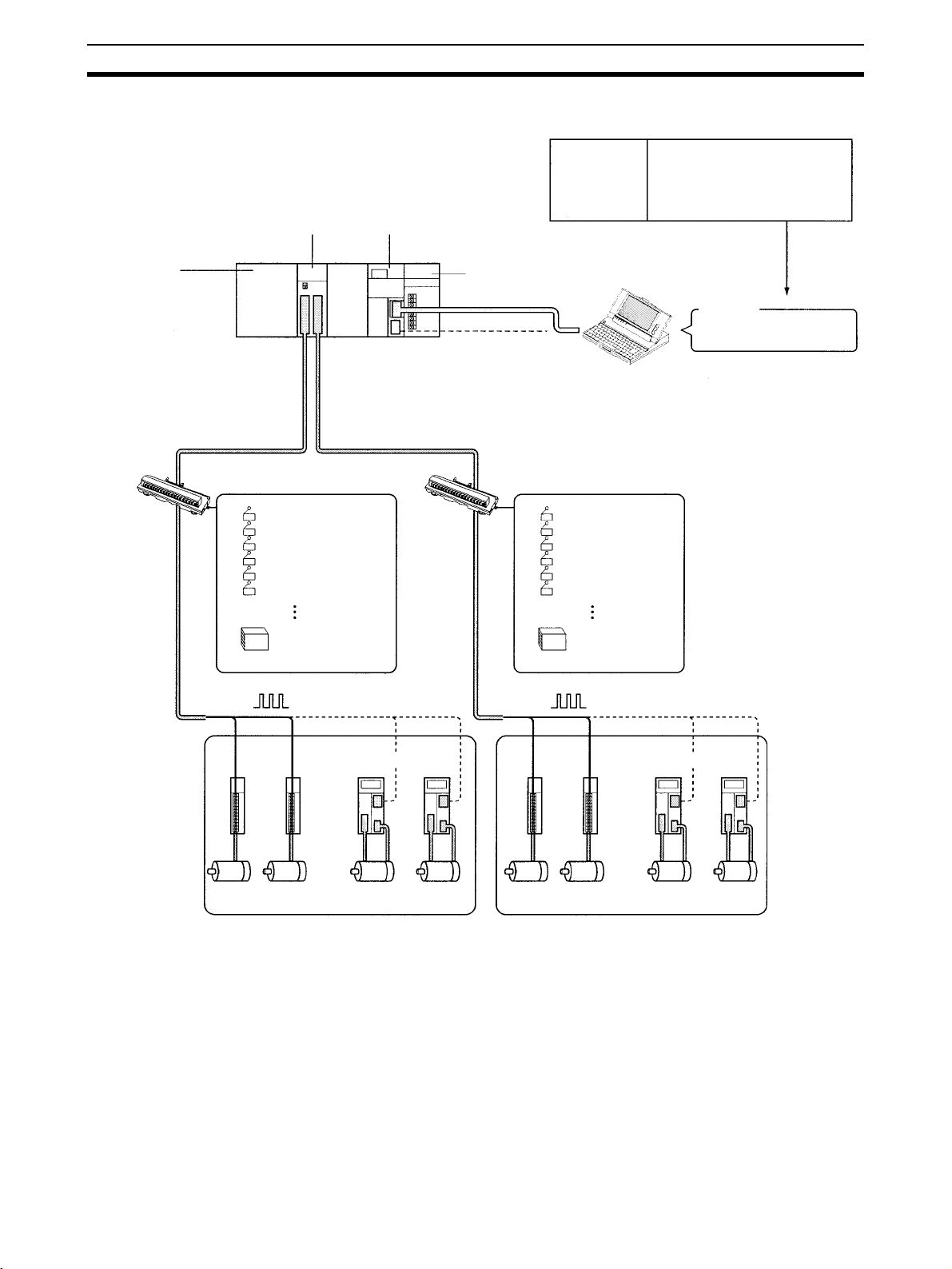
1-2-1 CS1W-NC413 System Configuration Example
Backplane
Dedicated
terminal block
(See note 1.)
CS1W-NC413
Position Control Unit
External input signals
CCW limit
CW limit
Origin (See note 2.)
Origin proximity
Emergency stop
External interrupt
CS1G/CS1H
CPU Unit
Dedicated
terminal block
Use for
setting data and
monitoring.
Power Supply Unit
Connection to peripheral port
Connection to
RS-232C port
External input signals
CCW limit
CW limit
Origin (See note 2.)
Origin proximity
Emergency stop
External interrupt
Editing parameters and data.
Monitoring status.
File management.
Computer:
CX-Position
CX-Programmer
Pulse output
Stepping
motor
drivers
Stepping motors
24-VDC power
supply for I/F
See
note 2.
or
Servo Drives
Servomotors
Pulse output
Stepping motors
24-VDC power
supply for I/F
Stepping
motor
drivers
See
note 2.
Servo Drives
or
Servomotors
Note (1) A dedicated cable is available for connecting the PCU to the dedicated
terminal block.
(2) Origin input signals cannot be used as external connection terminals with
dedicated terminal blocks. Connect the Z-phase signal to the Servo Drive
using the dedicated cable. The connecting cable required between the
PCU or dedicated terminal block and stepping motor driver is not provided.
4
Page 30

Basic Operations Section 1-3
1-3 Basic Operations
The PCU’s operations are as follows:
Position
Control Unit
functions
Position control Memory
operation
Direct operation
Interrupt feeding
Speed control
Other operations Origin search
Independent
Automatic
Continuous
Jogging
Teaching
Override
Present position
preset
Backlash
compensation
Zone setting
Deceleration stop
1-3-1 Position Control
Positioning can be executed with either an absolute value (i.e., to an absolute
position from the origin) or with an incremental value (i.e., to a relative position
from the present position).
There are two methods for positioning: memory operation and direct operation. Interrupt feeding, in which operation proceeds for a specified amount
after an interrupt input, is also possible.
Direct Operation With direct operation, positions and speeds are set directly from the CPU Unit
(ladder program), and positioning is executed according to operating commands. It is also possible to change the speed and send commands to move
5
Page 31

Basic Operations Section 1-3
to different positions while positioning is being performed. Linear interpolation,
however, is not possible during direct operation.
New target position
Speed
Position changed
Target position before
position changed
Start
Start
Time
Speed changed
Memory Operation With memory operation, positioning sequences (i.e., individual positioning
operations, which include data such as positions and speeds) are transferred
to the PCU in advance, and then positioning is executed from the CPU Unit by
specifying those positioning sequences by number. Depending on the completion code that is set, positioning sequences can be executed using independent positioning, automatic positioning, or continuous positioning. In the
following illustrations, “#0” “#1” “#2” and “#3” indicate positioning sequence
numbers.
P ecuted in Order
ositioning Sequences Ex
Speed
Independent
Positioning
Automatic
Positioning
Continuous
Positioning
"#0" "#1" "#2" "#3"
Time
Start
Stop
Start
Pauses for length
of dwell time that
is set.
Does not stop.
Interrupt Feeding When an interrupt input signal is received, positioning is continued for the
specified amount of pulses and then stopped.
Interrupt input signal
Speed
Specified amount
of pulses
Time
6
Page 32

Basic Operations Section 1-3
1-3-2 Speed Control
When a start is executed once, pulses are continuously output at a constant
rate. The pattern depends on the completion code that is set for “memory
operation” positioning sequences. To stop the sequence, use the STOP command.
Speed
Start
STOP
Time
1-3-3 Other Operations
Origin Search The origin search operation finds the origin for the designated axis.
Jogging The jogging operation moves a specified axis at a designated speed and then
stops it.
Teaching The teaching operation takes the present position for the specified positioning
sequence.
Origin
Present position
Specified positioning sequence number
Override When the override is enabled during positioning, the target speed is changed
to the override speed.
Changing the Present
Position
Speed
A x 1.5
A
Override enable
1
0
The PRESENT POSITION PRESET command changes the present position
to a specified position.
Override setting: 150%
Time
Backlash Compensation This operation compensates for the amount of mechanical play, or “loose-
ness,” present in gears.
7
Page 33

List of Functions Section 1-4
Zones A zone is a range of positions which can be defined so that flags are turned
ON whenever the present position is within the range.
CCW CW
Zone setting
Zone Flag
ON
OFF
Deceleration Stop The STOP command decelerates positioning to a stop.
STOP
Speed
1
0
Time
1-4 List of Functions
Group Name Function Page
Origin determination Origin search Starts the motor and establishes the origin. 145
Present position preset Sets the position at which the motor is stopped to a spec-
Origin return Returns the axis to the origin. 170
Direct operation Absolute/relative move-
ment
Interrupt feeding Designates position, speed, and acceleration/decelera-
Memory operation Absolute/relative move-
ment
Linear interpolation Continuously performs positioning by linear interpolation
Interrupt feeding Performs interrupt feeding according to positioning
Speed control Outputs pulses at a fixed speed according to positioning
Forced interrupt Stops the positioning operation currently being performed
Data saving/transfer High-speed transfer Transfers data between the CPU Unit and the PCU in a
Batch transfer Transfers a large amount of data in one operation
Saving Saves parameters, position data, and speed data to non-
ified value, and establishes the origin.
Designates position, speed, and acceleration/deceleration times, and carries out absolute or relative positioning.
tion times, and after the interrupt signal turns ON, moves
a specified amount before stopping.
Continuously performs absolute or relative positioning
according to positioning sequences previously set in the
PCU.
according to positioning sequences previously set in the
PCU.
sequences previously set in the PCU.
sequences set in the PCU.
and performs another positioning operation.
short time using the IOWR and IORD instructions in the
ladder program.
between the CPU Unit and the PCU.
volatile memory (flash memory) in the PCU.
169
176
233
194
211
233
210
236
129,
136
119,
124
140
8
Page 34

Specifications Section 1-5
Group Name Function Page
Common to direct operation and memory operation
Jogging Outputs pulses at a fixed speed in the CW or CCW direc-
Teaching Reads the currently stopped position as position data. 231
Deceleration stop Decelerates axes to a stop during positioning. Axes can-
Override Changes the axis speed during positioning. 243
Error counter reset Clears the error counter of the Servo Drive to 0. 247
Backlash compensation Increases positioning accuracy by compensating for play
Software limit In order to prevent damage to external devices due to
Zones Notifies the CPU whether or not the position is within a
Acceleration/deceleration curve, acceleration/
deceleration time designations
Initial pulse Starts pulse output in a short time in response to an oper-
Stop function Detects an error either at the CPU Unit or the PCU and
Release prohibit/error
reset
tion.
not be moved while the STOP Bit is ON.
in the mechanical system.
unexpected positioning caused by malfunction, in addition
to CW and CCW limit input signals, positioning is also
monitored using the software.
set region. This function is used when interlocking or performing simultaneous control with peripheral devices.
Performs acceleration/deceleration according to the basic
trapezoidal curve, or an S-curve that greatly helps to
reduce mechanical vibration. Specifies the method for
setting the acceleration/deceleration times.
ating command from the CPU Unit.
stops pulse output either with or without a deceleration
curve.
Releases the pulse output prohibit status and at the same
time clears the error code to 0.
229
238
250
252
103
86
92
255
333
1-5 Specifications
1-5-1 Basic Specifications
Item Model
CS1W-NC113/133 CS1W-NC213/233 CS1W-NC413/433
Power supply voltage 5 VDC (for the PCU itself)
24 VDC (external power supply)
5 VDC (external power supply; line driver output only)
Allowable power supply voltage range
Internal current consumption 250 mA max. at 5 VDC 250 mA max. at 5 VDC 360 mA max. at 5 VDC
Current consumption of
external power supply
External dimensions 130 (H) × 35 (W) × 101 (D) (all models)
Weight 250 g max. 250 g max. 300 g max.
Safety standards UL, CSA, EC (EMC Directive)
4.75 to 5.25 VDC (for the PCU itself)
21.6 to 26.4 VDC (external power supply)
4.75 to 5.25 VDC (external power supply; line driver output only)
NC113: 30 mA max. at
24 VDC
NC133: 10 mA max. at
24 VDC
NC133: 60 mA max. at
5VDC
NC213: 50 mA max. at
24 VDC
NC233: 20 mA max. at
24 VDC
NC233: 120 mA max. at
5VDC
NC413: 90 mA max. at
24 VDC
NC433: 30 mA max. at
24 VDC
NC433: 220 mA max. at
5VDC
Note Specifications not listed above conform to CS Series general specifications.
9
Page 35

Specifications Section 1-5
1-5-2 Performance Specifications
Item Model
CS1W-NC113/133 CS1W-NC213/233 CS1W-NC413/433
Applicable PLC models CS-series PLCs
I/O requirements Words 5 words 10 words 20 words
Slots 1 slot
Controlled driver Pulse-train input-type Servo Drive or stepping motor driver
NC113/213/413 models have open collector output.
NC133/233/433 models have line driver output.
Control Control system Open-loop control by pulse train output
Number of control
axes
Control unit Pulse
Positioning operations Two types: memory operation and direct operation
Independent 1 axis 2 independent axes 4 independent axes
Linear interpolation None 2 axes max. 4 axes max.
Speed control 1 axis 2 independent axes 4 independent axes
Interrupt feeding 1 axis 2 independent axes 4 independent axes
Positions Range –1,073,741,823 to 1,073,741,823 pulses (See note.)
Data items 100/axis
Speeds Range 1 pps to 500 Kpps
Data items 100/axis
Acceleration and
deceleration times
Functions and settings Origin search Origin proximity input signal: selectable (absent, N.O. or N.C. contact).
Range 0 to 250 s, until maximum speed is reached.
Data items 9/axis for acceleration and deceleration each
Jogging Jogging can be executed at a specified speed.
Dwell times 19/axis can be set from 0 to 9.99 s (unit: 0.01 s).
Acceleration/
deceleration curves
Zones Zone Flag turns ON when present position is within a specified zone.
Software limits Can be set within a range of –1,073,741,823 to 1,073,741,823 pulses.
Backlash compensation
Teaching With a command from the PLC, the present position can be taken as the
Deceleration stop The STOP command causes positioning to decelerate to a stop accord-
Emergency stop Pulse outputs are stopped by an external emergency stop command.
1 axis 2 axes 4 axes
Origin input signal: selectable (N.O. or N.C. contact)
Origin compensation: –1,073,741,823 to 1,073,741,823 pulses
Origin search speed: High-speed or proximity-speed can be set.
Origin detection method: May be set to stop upon origin input signal
after proximity input signal has turned ON, to stop upon origin input signal after proximity input signal has turned OFF, to stop upon origin input
signal without using proximity input signal, or to stop upon origin input
signal after limit input signal has turned OFF.
N.O. = Normally open
N.C. = Normally closed
Trapezoidal or S-curve (Can be set separately for each axis.)
Three zones can be set for each axis.
0 to 9,999 pulses. Compensation speed can also be set.
position data.
ing to the specified deceleration time.
10
Page 36

Comparison with Existing Models Section 1-6
Item Model
CS1W-NC113/133 CS1W-NC213/233 CS1W-NC413/433
Functions and settings Present position pre-
set
Override When the override enabling command is executed during positioning,
Data saving 1) Saving to flash memory. (Can be written 100,000 times.)
External I/O Inputs Prepare the following inputs for each axis:
Outputs Prepare the following outputs for each axis:
Pulse output distribution period 1-axis operation: 4 ms
Response time Refer to Appendix A Performance Characteristics.
Self-diagnostic function Flash memory check, memory loss check, CPU bus check
Error detection function Overtravel, CPU error, software limit over, emergency stop
The PRESENT POSITION PRESET command can be used to change
the present position to a specified value.
the target speed is changed by applying the override coefficient. Possible to set to a value from 1 to 999% (by an increment of 1%)
2) Reading from PLC area by data reading instruction.
3) Reading by Support Tool and saving to personal computer hard
disk or floppy disk.
CW and CCW limit input signals, origin proximity input signal, origin
input signal, emergency stop input signal, positioning completed signal,
interrupt input signal
Pulse outputs
CW/CCW pulses, pulse outputs and direction outputs can be switched.
Either error counter reset or origin-adjustment command outputs can be
selected depending on the mode.
Linear interpolation: 8 ms
Note (1) The additional functions supported by Unit version 2.0 can be used only
when the PCU is installed with a CS1-H CPU Unit (either CPU Unit Ver.
2.0 or Pre-Ver. 2.0 CPU Unit). These functions cannot be used if the PCU
is installed with a CS1 CPU Unit (with -V1 suffix).
For details on Unit versions, refer to Unit Versions of CS-series Position
Control Units on page vi. For details on additional functions supported for
unit version 2.0, refer to Unit Versions of CS-series Position Control Units
on page vi.
(2) When performing linear interpolation, the distances that can be moved
will vary. For details, refer to 8-6 Linear Interpolation.
1-6 Comparison with Existing Models
The differences between CS1W-NC113/133/213/233/413/433 and OMRON’s
C200HW-NC413/213/113 are given in the following table. When replacing the
C200HW-NC413/213/113 with this model, refer to Appendix D Replacing the
@
C200HW-NC
13.
11
Page 37

Comparison with Existing Models Section 1-6
Item CS1W-NC4@3/2@3/1@3 C200HW-NC413/213/113
Unit number allocation Allocate unit numbers in the range 0 to
Pulse output type 2 types: open collector output and line
Format of data exchanged between
PLC and PCU
Position designation range –1,073,741,823 to 1,073,741,823
Present position range –2,147,483,647 to 2,147,483,647
Zone range –1,073,741,823 to 1,073,741,823
Speed designation range 1 to 500,000 pps, set in pps units 1 to 500,000 pps, set in units of the
CPU Unit scan timeover for END
refresh
CPU Unit scan timeover due to IOWR/
IORD instruction
Time between startup instruction from
the ladder program and pulse output
Operating data area The following 3 areas can be specified:
Corresponding EM banks Banks 0 to C Bank 0 only
Clearing error codes Possible Not possible (only cleared to 0 when
Parameter setting Settings only required for the axes
Mounting on C200H Slave Rack
(remote I/O)
Support Software CX-Position
95.
1-axis and 2-axis PCUs: One unit num-
ber allocated
4-axis PCUs: 2 unit numbers allocated
driver output
Binary format (hexadecimal)
Example: Present position is output to
the PLC in 32-bit signed binary format.
pulses
pulses
pulses
0.5 ms max. per PCU 2.6 to 4.5 ms per PCU
1 ms max. per instruction 2.4 to 62 ms per instruction
2 ms max. (at optimum conditions) 7.51 ms max. (at optimum conditions)
DM Area words allocated to Special I/O
Units, user-specified DM Area words,
and user-specified EM Area words.
being used.
Not possible Possible
(Conversion of parameters and data
created using the SYSMAC-NCT possible.)
Allocate unit numbers in the range 0 to
15.
1-axis and 2-axis PCUs: One unit num-
ber allocated
4-axis PCUs: 2 unit numbers allocated
Open collector output only
BCD format
Example: Present position is output to
the PLC in BCD format.
–9,999,999 to 9,999,999 pulses
–9,999,999 to 9,999,999 pulses
–9,999,999 to 9,999,999 pulses
smallest multiplication factor specified
The following 2 areas can be specified:
User-specified DM Area words and
user-specified EM Area words.
(The DM Area words allocated to Special I/O Units cannot be specified.)
startup instruction is made)
Settings required for all axes.
SYSMAC-NCT
12
Page 38

Control System Principles Section 1-7
1-7 Control System Principles
1-7-1 Data Flow
Position Control Unit
Stepping motor driver
Pulse train
Stepping motor
CPU Unit
PC
BUS
MPU
I/F
Memory
Pulse
generator
I/O
interface
Pulse
generator
I/O connector
Magnetizing distribution circuit
Power
amplifier
External
input
I/O
interface
I/O connector
Pulse train
Servo Drive
Error counter Power amplifier
Servomotor
(Positioning output)
Tachogenerator
Rotary encoder
13
Page 39

Control System Principles Section 1-7
1-7-2 Control System Principles
Open-Loop System In an open-loop system, positioning is controlled according to the number of
input pulses that the motor receives, and no position feedback is provided.
The PCUs all employ pulse-output-type open-loop systems, and the most
commonly used motor for this type of control system is a stepping motor. The
angle of rotation of a stepping motor can be controlled through the number of
pulse signals supplied to the motor driver. The number of rotations of the stepping motor is proportional to the number of pulses supplied by the PCU, and
the rotational speed of the stepping motor is proportional to the frequency of
the pulse train.
Position controller
(e.g., PCU)
Stepping motor or
pulse-train input-type
servomotor
Pulse
train
Reduction gear
Turntable
Ball screw
1-7-3 Basic Positioning System Design
The following diagram and parameters illustrate a simplified positioning system.
M: Reduction ratio
P: Feed screw pitch (mm/revolution)
V: Feed velocity of object being positioned (mm/s)
θ
: Stepping angle per pulse (degree/pulse)
s
N
Stepping motor
Reduction gear
M
Object being
positioned
V
Feed screw pitch
P
The travel distance per pulse sent to the motor driver is called the “pulse rate”
and is calculated according to the following equation:
Pulse rate = P/(pulses per revolution x M)
= P/((360/
= (P x
θ
) x M))
s
θ
)/(360 x M)
s
Using the pulse rate, the number of pulses required to move the object a distance L is given by the following calculation:
No. of pulses = Travel distance
÷ Pulse rate
= L
÷ (P x θ
= L
= (360
× M × L)/(P x θ
÷ Pulse rate
)/(360 x M)
s
)
s
The pulse speed required to move the object with a feed speed of V mm/s is
given by the following calculation:
Pulse speed = Feed speed
÷ Pulse rate
= V
÷ (P x θ
= V
= (360
× M × V)/(P x θ
÷ Pulse rate
)/(360 x M)
s
)
s
The PCU performs positioning control by providing the number of pulses and
the pulse speed in the form of position instructions and speed instructions.
14
Page 40

Basic Procedures
This section gives an overview of the procedures required to use the Position Control Unit.
2-1 Basic Operational Flow. . . . . . . . . . . . . . . . . . . . . . . . . . . . . . . . . . . . . . . . . . 16
SECTION 2
15
Page 41

Basic Operational Flow Section 2-1
2-1 Basic Operational Flow
The following table shows the basic flow of operation for the PCU.
Flow of operation Reference
Installation SECTION 3 Installation and Wir-
Mount the PCU.
Set the unit number of the PCU.
START
ing
3-2 Installation
3-3 External I/O Circuitry
Wiring 3-4 Wiring
--- ---
Setting the
PCU
Connect the PCU to the external input device(s).
Connect the motor and the motor driver.
Connect the motor driver and the PCU.
Turn ON power to the CPU Unit.
Create I/O tables for the PC.
Set the common parameters for the PCU in
the DM Area of the CPU Unit.
(See note 3.)
When operating
according to the axis
parameters saved in
the PCU.
Set the axis parameters saved in the PCU.
Read the axis parameters saved in the PCU.
Write the axis parameters to the PCU.
Save the written axis parameters in the PCU.
Enable the set parameters by either turning the
power OFF and ON, or by restarting the PCU.
When operating according to the axis
parameters in the CPU Unit's DM Area.
Set the axis parameters for the PCU
in the CPU Unit's DM Area.
(See note 1.)
(See note 2.)
SECTION 4 Data Areas
4-2 Common Parameter Area
4-3 Axis Parameter Area
SECTION 5 Transferring and
Saving Data
5-3 Reading Data with the
READ DATA Bit
5-5 Reading Data with IORD
5-2 Writing Data with the
WRITE DATA Bit
5-4 Writing Data with IOWR
5-6 Saving Data
5-7 Transferring Data with
CX-Position
16
(Continued on next page.)
Page 42

Basic Operational Flow Section 2-1
Flow of operation Reference
Programming
and test operation
(Continued from previous page.)
Establish the origin of the motor axis
for operation.
SECTION 6 Defining the Origin
Directly set the target position and speed
from the CPU Unit and start the motor.
Record a positioning sequence (including
positions and speeds) and operate the
motor in accordance with this sequence.
Read the sequence data saved in the PCU.
Write the sequence data to the PCU.
Save the written sequence data in the PCU.
Execute other PCU functions, such as
jogging or teaching.
Debugging SECTION 11 Troubleshooting
Is there an error?
No
Check the LED indicators on the
front of the PCU.
Ye s
SECTION 7 Direct Operation
SECTION 8 Memory Operation
SECTION 9 Other Operations
Read the PCU's error code.
Remove the cause of the error
and clear the error status.
Operation SECTION 10 Program Exam-
Start PC (and PCU) operation.
Maintenance SECTION 12 Maintenance and
Perform regular inspections.
END
ples
Inspection
Note 1. Perform wiring according to instructions given in the motor and motor driv-
er’s operation manuals.
2. Refer to the operation manual for the CPU Unit.
3. Use the axis parameter designation setting in the common parameter area
to specify whether for operation is performed according to axis parameters
saved in the PCU or the axis parameters set in the CPU Unit’s DM Area.
17
Page 43

Basic Operational Flow Section 2-1
18
Page 44

SECTION 3
Installation and Wiring
This section provides information on nomenclature and the function of each part, describes the procedures required for
wiring and installation, and gives connection examples. Information on using Servo Relay Units is also provided.
3-1 Nomenclature and Functions . . . . . . . . . . . . . . . . . . . . . . . . . . . . . . . . . . . . . 20
3-1-1 Area Allocation. . . . . . . . . . . . . . . . . . . . . . . . . . . . . . . . . . . . . . . . . 22
3-2 Installation. . . . . . . . . . . . . . . . . . . . . . . . . . . . . . . . . . . . . . . . . . . . . . . . . . . . 22
3-2-1 System Configuration Considerations . . . . . . . . . . . . . . . . . . . . . . . 22
3-2-2 Mounting the Unit. . . . . . . . . . . . . . . . . . . . . . . . . . . . . . . . . . . . . . . 23
3-2-3 Precautions When Handling the PCU. . . . . . . . . . . . . . . . . . . . . . . . 24
3-2-4 Dimensions . . . . . . . . . . . . . . . . . . . . . . . . . . . . . . . . . . . . . . . . . . . . 25
3-3 External I/O Circuitry . . . . . . . . . . . . . . . . . . . . . . . . . . . . . . . . . . . . . . . . . . . 26
3-3-1 Connector Pin Arrangement . . . . . . . . . . . . . . . . . . . . . . . . . . . . . . . 26
3-3-2 External I/O Connector Arrangement. . . . . . . . . . . . . . . . . . . . . . . . 29
3-3-3 I/O Circuitry . . . . . . . . . . . . . . . . . . . . . . . . . . . . . . . . . . . . . . . . . . . 31
3-3-4 I/O Electrical Specifications . . . . . . . . . . . . . . . . . . . . . . . . . . . . . . . 34
3-4 Wiring . . . . . . . . . . . . . . . . . . . . . . . . . . . . . . . . . . . . . . . . . . . . . . . . . . . . . . . 35
3-4-1 Output Connection Examples. . . . . . . . . . . . . . . . . . . . . . . . . . . . . . 35
3-4-2 Connecting Input Signals . . . . . . . . . . . . . . . . . . . . . . . . . . . . . . . . . 41
3-4-3 Connecting Origin and Positioning Completed Input Signals . . . . . 42
3-4-4 Wiring Precautions . . . . . . . . . . . . . . . . . . . . . . . . . . . . . . . . . . . . . . 43
3-5 Connection Examples for Different Types of Motor Driver . . . . . . . . . . . . . . 45
3-6 Connection of Unused Axes . . . . . . . . . . . . . . . . . . . . . . . . . . . . . . . . . . . . . . 58
3-6-1 Using Only the X Axis and Not the Y Axis on the CS1W-NC213/
NC233 (with Unit Version 2.1 or Later). . . . . . . . . . . . . . . . . . . . . . 58
3-6-2 CS1W-NC213/NC233 – X Axis Only (Unit Versions Earlier Than 2.1) 59
3-7 Servo Relay Unit. . . . . . . . . . . . . . . . . . . . . . . . . . . . . . . . . . . . . . . . . . . . . . . 59
19
Page 45

Nomenclature and Functions Section 3-1
3-1 Nomenclature and Functions
CS1W-NC4 3 CS1W-NC2 3 CS1W-NC1 3
LED indicators
Show the PCU's
operating status.
Unit number setting
switch
Sets the unit number
for the PCU.
X axis
X/Y axis connector
connector
X/Y axis
connector
Connect to
stepping
motor driver
or Servo
Drive. (Controls 2 axes).
Z/U axis connector
Connect to stepping
motor driver or Servo
Drive. (Controls 2
axes).
Note The orientation of connectors for 2-axis and 4-axis PCUs is the opposite to
that of the C200HW-NC213/413 connectors.
20
Page 46

Nomenclature and Functions Section 3-1
LED Indicators
Name Color Status Explanation
RUN Green Lit Lit during normal operation.
Not lit Hardware error, or PLC notified of PCU error.
ERC Red Lit An error has occurred.
Not lit No error has occurred.
ERH Red Lit An error has occurred IN the CPU Unit.
Not lit No error has occurred at the CPU Unit.
SENS Yellow Lit Either a CW/CCW limit signal or an emergency stop input signal is being input. At
Flashing Either a parameter loss, a data loss, or an operating data area designation error
Not lit None of the above has occurred.
DATA Yellow Lit Data is incorrect (e.g., the parameters or positions transferred are out of the per-
Flashing The check of all data (parameters, positions, etc.) following power up shows that
Not lit None of the above has occurred.
X Orange Lit Pulses are being output to the X axis (either forward or reverse).
Flashing An error has occurred, such as incorrect cable type for the X axis or faulty data.
Not lit None of the above has occurred.
Y Orange Lit Pulses are being output to the Y axis (either forward or reverse).
Flashing An error has occurred, such as incorrect cable type for the Y axis or faulty data.
Not lit None of the above has occurred.
Z Orange Lit Pulses are being output to the Z axis (either forward or reverse).
Flashing An error has occurred, such as incorrect cable type for the Z axis or faulty data.
Not lit None of the above has occurred.
U Orange Lit Pulses are being output to the U axis (either forward or reverse).
Flashing An error has occurred, such as incorrect cable type for the U axis or faulty data.
Not lit None of the above has occurred.
Note For details regarding errors, refer to SECTION 11 Troubleshooting.
this time the LED indicator for the relevant axis (X to U) will flash.
has occurred.
missible range). At this time the LED indicator for the relevant axis (X to U) will
flash.
data is lost or corrupted.
Unit Number Setting
Switch
• For the CS1W-NC113/NC133, this applies only to the X axis; for the
CS1W-NC213/NC233, it applies only to the X and Y axes.
• When not all of the axes are used for the CS1W-NC213/NC233/ NC413/
NC433, either connect the CW/CCW limit inputs for the unused axes to
the input power supply and turn them ON or set the contact logic to N.O.
Connect the emergency stop to the input common and turn it ON. If it is
not connected, the ERC indicator will light. Operation will be normal, however, for all axes that are used.
This switch sets the unit number (i.e., the machine number) for the PCU as a
Special I/O Unit.
Memory is allocated to the PCU from the CPU Unit’s Special I/O Unit Area
according to the unit number setting.
CS1W-NC113/NC133/NC213/NC233 models are allocated 10 words and
CS1W-NC413/NC433 models are allocated 20 words. The following unit number settings are possible:
21
Page 47

Installation Section 3-2
• CS1W-NC113/NC133/NC213/NC233: 0 to 95
• CS1W-NC413/NC433: 0 to 94
As long as the unit number settings do not overlap with those of other Special
I/O Units, any unit numbers in the ranges given above can be set.
!Caution Be sure to turn OFF the power supply before making the settings.
3-1-1 Area Allocation
DM Area for Special I/O
Units
CS1W-NC113/NC133/NC213/NC233 PCUs occupy 100 words each and
CS1W-NC413/NC433 PCUs occupy 200 words each from D20000 to D29599
in the DM Area as shown below.
CS1W-NC113/NC133/NC213/NC233 CS1W-NC413/NC433
D20000 to D20099 Unit #0
D20100 to D20199 Unit #1
D20200 to D20299 Unit #2
D20300 to D20399 Unit #3
: :
D29300 to D29399 Unit #93
D29400 to D29499 Unit #94
D29500 to D29599Unit #95
Unit #0 D20000 to D20199
Unit #1 D20100 to D20299
Unit #2 D20300 to D20399
Unit #3 D20400 to D20499
: :
Unit #93 D29300 to D29499
Unit #94 D29400 to D29599
Unit #95 Setting not possible.
Word address
m to m+3
m+4 to m+31
m+32 to m+59
m+60 to m+87
m+88 to m+115
m: D20000+100 x unit number
Contents
Common parameters
Axis
parameters
For X axis
For Y axis
For Z axis
For U axis
Special I/O Unit Area CS1W-NC113/NC133/NC213/NC233 PCUs occupy 10 words, and CS1W-
NC413/NC433 PCUs occupy 20 words in the Special I/O Unit Area.
CS1W-NC113/NC133/NC213/NC233 CS1W-NC113/NC133
Unit #0
Unit #1
Unit #2
Unit #3
Unit #93
Unit #94
Unit #95
CS1W-NC413/NC433 CS1W-NC413/NC433
CIO 2000 to CIO 2009
CIO 2010 to CIO 2019
CIO 2020 to CIO 2029
CIO 2030 to CIO 2039
:
CIO 2930 to CIO 2939
CIO 2940 to CIO 2949
CIO 2950 to CIO 2959
CIO 2000 to CIO 2019 Unit #0
CIO 2010 to CIO 2029 Unit #1
CIO 2020 to CIO 2039 Unit #2
CIO 2030 to CIO 2049Unit #3
:
CIO 2930 to CIO 2949 Unit #93
CIO 2940 to CIO 2959Unit #94
Setting not possible.Unit #95
:
:
I/O
Output
I/O
Output
Input
Word address Axis
n to n+1
n+2 to n+4 Input X axis
Word address Axis
n to n+1 X axis
n+2 to n+3 Y axis
n+4 to n+5 Z axis
n+8 to n+10 X axis
n+11 to n+13 Y axis
n+14 to n+16 Z axis
n+17 to n+19 U axis
X axis
CS1W-NC213/NC233
I/O
Output
Input
n: CIO 2000+10 x unit number
U axisn+6 to n+7
Word address Axis
n to n+1 X axis
n+2 to n+3 Y axis
n+4 to n+6 X axis
Y axisn+7 to n+9
Note 1. The CS1W-NC413/NC433 occupies the space for two unit numbers, i.e.,
the unit number that is set and also the following number.
2. Be sure to set the unit numbers so that they do not overlap with the unit
numbers of other Special I/O Units.
3. Since the CS1W-NC413/433 occupies the space for two unit numbers, unit
number 95 cannot be set.
3-2 Installation
3-2-1 System Configuration Considerations
• The additional functions supported by Unit version 2.0 can be used only
when the PCU is installed with a CS1-H CPU Unit (either CPU Unit Ver.
2.0 or Pre-Ver. 2.0 CPU Unit). These functions cannot be used if the PCU
is installed with a CS1 CPU Unit (with -V1 suffix).
For details on Unit versions, refer to Unit Versions of CS-series Position
22
Page 48

Installation Section 3-2
Control Units on page vi. For details on additional functions supported for
unit version 2.0, refer to Unit Versions of CS-series Position Control Units
on page vi.
• The I/O bits allocated to a particular Special I/O Unit are determined by
the unit number that is set by the switch on the front panel of the Unit, and
not by the slot in which the Unit is mounted.
• The PCU can be mounted to CS1W-BC@@3 CPU Backplanes or CS1WBI@@3 Expansion Backplanes.
3-2-2 Mounting the Unit
Follow the procedure outlined below to mount the Position Control Unit.
1,2,3... 1. Hook the top of the PCU into the slot in the Backplane.
Hook
Duct
PCU
Duct
Phillips-head screwdriver
Backplane
2. Carefully insert the PCU into the connector on the Backplane.
3. Tighten the screw on the bottom with a Phillips-head screwdriver. Provide
enough space around the PCU to enable easy mounting and dismounting,
and to ensure good ventilation as shown below.
20 mm min.
Backplane
20 mm min.
Note Tighten the screw at the bottom of the PCU to a torque of 0.4 N
4. To remove the PCU, use a Phillips-head screwdriver to loosen the screw
at the bottom of the PCU, and rotate the PCU upwards before dismounting.
•m.
23
Page 49

Installation Section 3-2
3-2-3 Precautions When Handling the PCU
• Before installing or disconnecting the PCU or connecting cable, be sure to
first turn off both the Programmable Controller and the power supply.
• To minimize any influence from noise, place I/O wiring, high-voltage lines,
and power lines in separate ducts.
• Wire clippings tend to get scattered around during wiring, so leave the
label in place on top of the PCU to prevent any clippings from getting
inside the PCU. Once the wiring has been completed, be sure to remove
the label to provide ventilation.
Remove the label after
completing the wiring.
24
Page 50
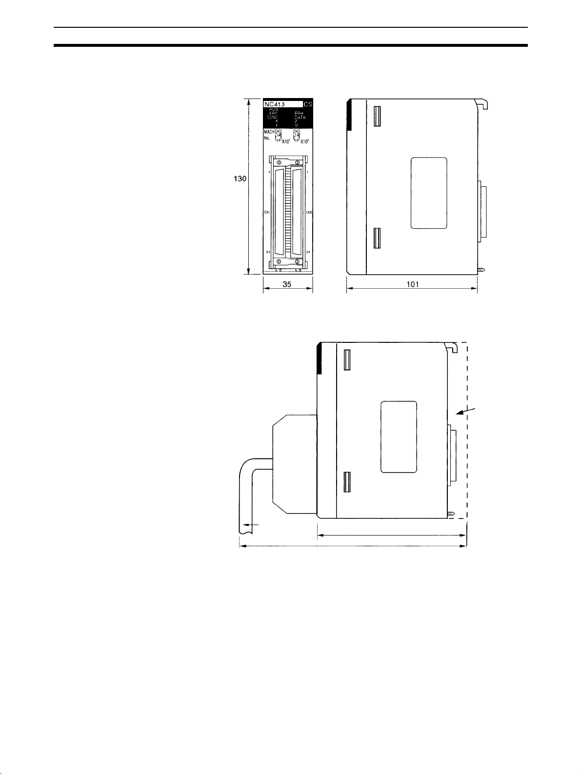
Installation Section 3-2
3-2-4 Dimensions
CS1W-NC113/NC133/NC213/NC233/NC413/NC433
Note The above diagram is for the CS1W-NC413.
Mounted Dimensions
Connecting
cable
Backplane
117
Approx. 230
25
Page 51

External I/O Circuitry Section 3-3
3-3 External I/O Circuitry
3-3-1 Connector Pin Arrangement
X/Y axis Z/U axis X/Y axis X axis
CS1W-NC413/433 CS1W-NC213/233 CS1W-NC113/133
26
Page 52

External I/O Circuitry Section 3-3
CS1W-NC113/213/413 (Pulse Open Collector Output)
Connector pin arrangement for X and Z axes Connector pin arrangement for Y and U axes
Pin
I/O Designation Pin
No.
A1 IN Output power supply, 24 VDC B1 IN Output power supply, 24 VDC
A2 IN Output GND, 24 VDC B2 IN Output GND, 24 VDC
A3 --- Not used B3 --- Not used
A4 --- Not used B4 --- Not used
A5 OUT CW pulse output B5 OUT CW pulse output
A6 OUT CW pulse output with 1.6-kΩ resistance B6 OUT CW pulse output with 1.6-kΩ resistance
A7 OUT CCW pulse/direction output B7 OUT CCW pulse/direction output
A8 OUT CCW pulse/direction output with 1.6-kΩ
resistance
A9 --- Not used B9 --- Not used
A10 OUT Error counter reset output/origin-adjustment
command output
A11 OUT Error counter reset output with 1.6-kΩ resis-
tance
Origin-adjustment command output with 1.6kΩ resistance
A12 IN Positioning completed input signal B12 IN Positioning completed input signal
A13 --- Not used B13 --- Not used
A14 IN Origin common B14 IN Origin common
A15 IN Origin input signal (24 V) B15 IN Origin input signal (24 V)
A16 IN Origin input signal (5 V) B16 IN Origin input signal (5 V)
A17 --- Not used B17 --- Not used
A18 --- Not used B18 --- Not used
A19 IN Interrupt input signal B19 IN Interrupt input signal
A20 IN Emergency stop input signal B20 IN Emergency stop input signal
A21 IN Origin proximity input signal B21 IN Origin proximity input signal
A22 IN CW limit input signal B22 IN CW limit input signal
A23 IN CCW limit input signal B23 IN CCW limit input signal
A24 IN Input common B24 IN Input common
No.
B8 OUT CCW pulse/direction output with 1.6-kΩ
B10 OUT Error counter reset output/origin-adjustment
B11 OUT Error counter reset output with 1.6-kΩ resis-
I/O Designation
resistance
command output
tance
Origin-adjustment command output with 1.6kΩ resistance
27
Page 53

External I/O Circuitry Section 3-3
CS1W-NC133/233/433 (Line Driver Output)
Connector pin arrangement for X and Z axes Connector pin arrangement for Y and U axes
Pin
No.
A1 IN Output power supply, 24 VDC B1 IN Output power supply, 24 VDC
A2 IN Output GND, 24 VDC B2 IN Output GND, 24 VDC
A3 IN Pulse output GND, 5 VDC* B3 IN Pulse output GND, 5 VDC*
A4 IN Pulse output power supply, 5 VDC* B4 IN Pulse output power supply, 5 VDC*
A5 OUT CW pulse output (+) B5 OUT CW pulse output (+)
A6 OUT CW pulse output (–) B6 OUT CW pulse output (–)
A7 OUT CCW pulse/direction output (+) B7 OUT CCW pulse/direction output (+)
A8 OUT CCW pulse/direction output (–) B8 OUT CCW pulse/direction output (–)
A9 --- Not used B9 --- Not used
A10 OUT Error counter reset output/origin-adjustment
A11 OUT Error counter reset output with 1.6-kΩ resis-
A12 IN Positioning completed input signal B12 IN Positioning completed input signal
A13 --- Not used B13 --- Not used
A14 IN Origin common B14 IN Origin common
A15 IN Origin input signal (24 V) B15 IN Origin input signal (24 V)
A16 IN Origin input signal (5 V) B16 IN Origin input signal (5 V)
A17 --- Not used B17 --- Not used
A18 --- Not used B18 --- Not used
A19 IN Interrupt input signal B19 IN Interrupt input signal
A20 IN Emergency stop input signal B20 IN Emergency stop input signal
A21 IN Origin proximity input signal B21 IN Origin proximity input signal
A22 IN CW limit input signal B22 IN CW limit input signal
A23 IN CCW limit input signal B23 IN CCW limit input signal
A24 IN Input common B24 IN Input common
I/O Designation Pin
No.
B10 OUT Error counter reset output/origin-adjustment
command output
B11 OUT Error counter reset output with 1.6-kΩ resis-
tance
Origin-adjustment command output with
1.6-kΩ resistance
* Be sure to wire the 5-VDC pulse output power supply with the correct polar-
ity.
I/O Designation
command output
tance
Origin-adjustment command output with 1.6kΩ resistance
28
Note 1. Use either the 24-V origin input signal or the 5-V origin input signal, but not
both.
2. Use 24
3. Use 5
±10% VDC as the output power supply.
±5% VDC as the output power supply.
4. Do not use the 24-VDC output power supply or the 5-VDC pulse output
power supply together with the power supply for another input or output.
5. Be sure to wire the 5-VDC pulse output power supply with the correct polarity. Wiring with the polarity reversed will result in damage to internal elements.
6. The leakage current must be less than 1.0 mA when two-wire-type sensors
are used.
7. Be sure to connect a load to the output terminals. If the load is short-circuited, it will damage the PCU’s internal components.
8. The 24-V output power supply (A1 and B1) and the 24-V output ground (A2
and B2) for all axes are connected in the PCU, and are shared by all axes.
9. The 5-V pulse output power supply (A4 and B4) and the 5-V pulse output
ground (A3 and B3) for all axes are connected in the PCU, and are shared
by all axes.
Page 54

External I/O Circuitry Section 3-3
10. When installing connectors to the PCU, tighten the connector screws to a
torque of 0.34 N·m.
• The commons for all outputs are connected to the 24-V output ground.
• The commons for all inputs except for the 24-V and 5-V origin input signals and positioning completed input signals are connected to the input
common.
• The common for the positioning completed input signal is connected to
the 24-V output power supply via a diode.
• Use the origin common as a pair with the 24-V origin input signal or the 5V origin input signal.
3-3-2 External I/O Connector Arrangement
• The connectors that are included with this PCU are solder-type connectors.
• Use wires with cross-sectional areas of 0.2 mm
• Be careful not to short-circuit neighboring terminals when soldering.
• Cover the soldered part of the wire with insulation tubing.
Wiring Power Lines
2
or less.
Connector Pin Numbers
Pin number marks
A1
A2
A3
A4
A5
A6
A23
A24
Outline of connector
(rear panel)
(Connector viewed from unit side.)
5 1
Insulator
Lead
Connector
AB
B1
B2
B3
B4
B5
B6
B23
B24
29
Page 55

External I/O Circuitry Section 3-3
Assembling Connectors Supplied with the PCU
M2x8 pan-head screws (two)
Connector
The following connectors (Fujitsu 360 Jack) can be used:
1,2,3... 1. FCN-361J048-AU (solder-type)
FCN-360C048-D (connector cover)
2. FCN-363J048 (crimp-type housing)
FCN-363J-AU/S (contact)
FCN-360C048-D (connector cover)
3. FCN-367J048-AU (crimp type)
Cover Dimensions
Cable holder
M2 nut (four)
M2x6 pan-head screws (two)
Cable holder (two)
Case
Screw (two)
30
Page 56

External I/O Circuitry Section 3-3
3-3-3 I/O Circuitry
Outputs (Open Collector Output)
Constant
voltage
circuit
1.6k Ω (1/2W)
1.6 kΩ (1/2W)
Output power supply, 24 VDC
Output GND, 24 VDC
CW pulse/pulse output
(with 1.6 kΩ resistance)
CW pulse output
CCW pulse/direction output
(with 1.6 kΩ resistance)
CCW pulse/direction output
See
note.
Note Output switching depends on the
axis parameter settings.
(Refer to 4-3 Axis Parameter
Area)
1.6 kΩ (1/2W)
Error counter reset output (with 1.6 kΩ
resistance)
Origin-adjustment command output (with
1.6 kΩ resistance)
Error counter reset output
Origin-adjustment command output
Note Output Circuits:
The pulse output and error counter reset circuitry of the PCU are provided
with two types of terminals: terminals with 1.6 k
Ω (1/2 W) limit resistance and
terminals with no resistance. Select the terminals in accordance with the
power requirements and the specifications of the motor driver to be used.
!Caution Connect a load of 7 to 30 mA (or 7 to 16 mA for terminals with 1.6-k
resistance) to the output section. If a current greater than this is used, it will
cause damage to the PCU’s internal components. Also, be sure to use the
CW/CCW output method when using pulse output terminals with limit resistance.
Ω limit
31
Page 57

External I/O Circuitry Section 3-3
Open collector output Open collector output with 1.6 kΩ series resistance
7 to 30 mA
Output transistor
(Circuit example)
PCU
Output
Output
7 to 16 mA
Add bypass resistance for loads less than 7 mA.
24 VDC
power
supply
7 mA
1 mA
Bypass resistance
6 mA
Driver
Outputs (Line Driver Output)
Note Error counter reset output is open collector output.
!Caution Connect a load of 20 mA max. to the output section. If a current greater than
!Caution Be sure to wire the 5-VDC pulse output power supply with the correct polarity.
Pulse output power supply, 5 VDC
A4/B4
Pulse output GND, 24 VDC
A3/B3
CW pulse output (+)
A5/B5
CW pulse output (–)
A6/B6
CCW pulse/direction output (+)
A7/B7
CCW pulse/direction output (–)
A8/B8
this is used, it will cause damage to the PCU’s internal components.
Wiring with the polarity reversed will result in damage to internal elements.
32
Page 58

External I/O Circuitry Section 3-3
Inputs
Output power supply, 24 VDC
680 Ω
680 Ω 4.7 kΩ (1/2W)
680 Ω 4.7 kΩ (1/2W)
680 Ω 4.7 kΩ (1/2W)
4.7 kΩ (1/2W)
Positioning completed input signal
Input common
External interrupt input (N.O. contact)
Emergency stop (N.C. contact)
(see note)
Origin proximity input
(N.O./N.C. contact) (see
note)
680 Ω 4.7 kΩ (1/2W)
CW limit input (N.O./N.C.
contact) (see note)
680 Ω
680 Ω
4.7 kΩ (1/2W)
4.7 kΩ (1/2W)
150 Ω
CCW limit input (N.O./N.C.
contact) (see note)
Origin input signal (24 V)
(N.O./N.C. contact) (see note)
Origin input signal
(N.O./N.C. contact) (see
note)
Origin common
Line driver output
For details on connecting origin input signals, refer to 42.
!Caution Use either the 24-VDC origin input signal or the 5-VDC origin input signal, but
not both. If both are connected it will damage the internal circuitry.
Do not connect the 5-VDC origin input signal input to any output circuit except
the line driver.
33
Page 59

External I/O Circuitry Section 3-3
3-3-4 I/O Electrical Specifications
Input Specifications
Item Specification
Voltage 24 VDC ±10%
Current 4.66 to 5.15 mA (at 24 V) typ.
ON voltage 17 VDC min.
OFF voltage 5.0 VDC max.
Origin-signal Input
Specifications
ON response time 1 ms max. (0.1 ms max.: Interrupt input
OFF response time 1 ms max.
Item Connection
External signal is
open collector
signal
External signal is
line driver signal
Ter m inal
X/Z Axis A15
A14
Y/U Axis B15
B14
X/Z Axis A16
A14
Y/U Axis B16
B14
and origin input)
Specification Response
Conform to above input
specifications
Signal is a line driver output
signal corresponding to
Am26LS31
Time
N.O. contact:
0.1 ms max.
N.C. contact:
1 ms max.
N.O. contact:
0.1 ms max.
N.C. contact:
1 ms max.
Output Specifications
CW/CCW Pulse Output
Specifications (Open
Collector Output)
Item Specification
Open collector output
Line driver output Corresponds to Am26LS31.
External power supply 24 VDC ±10% NC413: 90 mA max.
Maximum switching
capacity
Minimum switching
capacity
Leakage current 0.1 mA max.
Residual voltage 0.6 V max. (pulse output)
30 mA at 4.75 to 26.4 VDC (NPN open collector)
(16 mA: Terminals with 1.6-kΩ limit resistance)
7 mA at 4.75 to 26.4 VDC (NPN open collector)
1.0 V max. (error counter reset output)
Maximum output current: 20 mA
NC213: 50 mA max.
NC113: 30 mA max.
NC433: 30 mA max.
NC233: 20 mA max.
NC133: 10 mA max.
5 VDC±5% NC433: 220 mA max.
NC233: 120 mA max.
NC133: 60 mA max.
The minimum CW/CCW pulse widths are shown below.
The OFF and ON refer to the output transistor.
The output transistor is ON at level “L.”
34
B
OFF
90%
10%
ON
A
Page 60

Wiring Section 3-4
Pulse
frequency
50 Kpps 9.7 µs min. 9.7 µs min. 9.8 µs min. 9.8 µs min. 9.7 µs min. 9.7 µs min. 9.7 µs min. 9.7 µs min.
100 Kpps 4.7 µs min. 4.7 µs min. 4.8 µs min. 4.8 µs min. 4.7 µs min. 4.7 µs min. 4.8 µs min. 4.8 µs min.
200 Kpps 2.3 µs min. 2.3 µs min. 2.3 µs min. 2.3 µs min. 2.2 µs min. 2.2 µs min. 2.3 µs min. 2.3 µs min.
500 Kpps 0.76 µs
7 mA/5 VDC±5% 30 mA/5 VDC±5% 7 mA/24 VDC±10%
ABABABAB
min.
0.82 µs
min.
Open or close current / Loaded power-source voltage
(1.6-kΩ resistance)
0.77 µs
min.
0.88 µs
min.
0.74 µs
min.
0.72 µs
min.
16 mA/24 VDC±10%
(1.6-kΩ resistance)
0.76 µs
min.
0.85 µs
min.
Note 1. The load in the above table is the net resistance load, and the connecting
cable impedance with the load is not considered.
2. Due to distortions in pulse waveforms as a result of connecting cable impedance, pulse widths during actual usage may be smaller than those
shown in the above table.
3-4 Wiring
This section provides motor driver connection examples. When actually connecting a motor driver, be sure to first check the specifications of the motor
driver to be used.
The maximum length of the wiring between the PCU and the motor driver is 2
m for open collector output models and 5 m for line driver output models.
3-4-1 Output Connection Examples
Pulses are not output when the output transistor in the pulse output section is
OFF. (For direction output, OFF indicates CCW.)
Do not use a 24-VDC/5-VDC power supply for pulse output in common with
the power supply for other I/O.
ON
Output transistor
OFF
CW/CCW Pulse Outputs
CW
CCW
Pulse and Direction Outputs
During pulse output
CW CCW
CW CCW
Pulses
Direction
Output ON
Output OFF
35
Page 61

Wiring Section 3-4
Outputting CW and CCW
Pulses, Example 1
Position Control Unit
(open collector output)
24-VDC
input
CW pulse
output
CCW pulse
output
1.6 kΩ
1.6 kΩ
In this example, a 5-VDC photocoupler input motor driver is used for outputting CW and CCW pulses.
24-VDC
power
supply
+–
A1/B1
A6/B6
Approx.
12 mA
A8/B8
Approx.
12 mA
A2/B2
Motor driver (for 5-VDC input)
(For example R=220 Ω)
+
–
+
–
Note In this example, the 1.6 k
power supply to be used with a motor driver rated at 5 VDC.
When wiring your system, carefully note the current required by the motor
driver in order to avoid damaging the input circuitry of the motor driver.
Ω resistors of the PCU are used to allow a 24-VDC
36
Page 62

Wiring Section 3-4
Outputting CW and CCW
Pulses, Example2
Position Control Unit
(open collector output)
24-VDC
input
CW pulse
output
CCW pulse
output
1.6 kΩ
1.6 kΩ
In this example, a 5-VDC photocoupler input motor driver is used for outputting CW and CCW pulses.
24-VDC
power
supply
+–
A1/B1
A5/B5
A7/B7
A2/B2
5-VDC
power
supply
+–
Motor driver (for 5-VDC input)
+
–
+
–
Position Control Unit
(line driver output)
5-VDC input
CW pulse or
pulse
(CW+CCW)
output
CCW pulse or
direction output
5-VDC
power
supply
Motor driver (for 5-VDC input)
37
Page 63

Wiring Section 3-4
Outputting Pulse and
Direction Signals
Position Control Unit
(open collector output)
24-VDC
input
Pulse
(CW+CCW)
output
Direction
output
1.6 kΩ
1.6 kΩ
In this example, a 5-VDC input motor driver is used for outputting pulse and
direction signals.
24-VDC
power
supply
Motor driver (for 5-VDC input)
Direction input
Pulse input
A1/B1
A5/B5
A7/B7
A2/B2
+
7 to 30 mA
7 to 30 mA
–
When voltage-level output is used, the level is L for output ON, and H for output OFF.
38
Page 64

Wiring Section 3-4
Outputting CW and CCW
Pulses or Pulse and
Direction Signals
Position Control Unit
(line driver output)
5-VDC input
CW pulse or
pulse
(CW+CCW)
output
CCW pulse or
direction output
In this example, a motor driver with a line receiver input is used and either CW
and CCW pulses or pulse and direction signals are output.
5-VDC
power
supply
SG
Motor driver
(line receiver input
specifications)
(See note.)
Note: When connecting a line receiver,
connect the signal ground (SG) of
the motor driver's line receiver input
to the ground (GND) of the 5-VDC
power supply.
!Caution Be sure to wire the 5-VDC pulse output power supply with the correct polarity.
Wiring with the polarity reversed will result in damage to internal elements.
39
Page 65
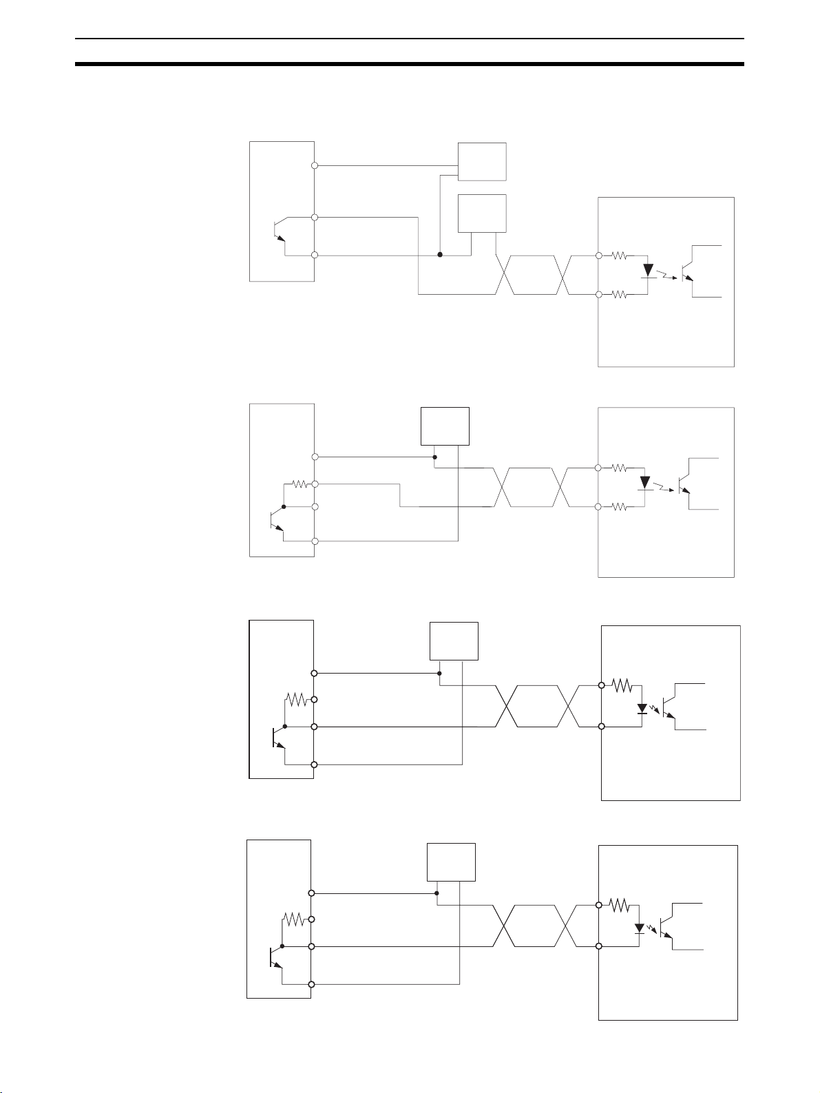
Wiring Section 3-4
Error Counter Reset
Output
There is approximately 20 ms of output when origin search is completed in
modes 1 or 2.
Position Control Unit
24-VDC
24-VDC
power
supply for
output
Position Control Unit
24-VDC
power
supply for
output
1.6 kΩ
A1/B1
A10/B10
A2/B2
A1/B1
A11/B11
A2/B2
+
power
supply
−
5-VDC
power
supply
24-VDC
power
supply
+–
OMRON R88D-WT
Servo Drive
+−
+ECRST
15
14
−ECRST
OMRON R88D-WT
Servo Drive
+ECRST
15
14
−ECRST
Position Control Unit
24-VDC
power
supply for
output
1.6 kΩ
Position Control Unit
24-VDC
power
supply for
output
1.6 kΩ
A1/B1
A10/B10
A2/B2
A1/B1
A10/B10
A2/B2
OMRON R88D-GT
Servo Drive
24-VDC
power
supply
−+
+24VIN
7
30
ECRST
OMRON R7D-BP
Servo Drive
24-VDC
power
supply
−+
+24VIN
1
4
ECRST
40
Page 66

Wiring Section 3-4
3-4-2 Connecting Input Signals
!Caution If the switching capacity is too low it may cause damage to the switch. Con-
nect a switch with a switching capacity of at least 5 mA for each input.
With N.C. inputs, be sure to connect a power supply for unused terminals and
turn them on.
This section shows examples of connecting interrupt, emergency stop, and
CW/CCW limit input signals.
The input section has both N.O. and N.C. inputs. Either can be used depending on the axis parameter settings. For details regarding axis parameters,
refer to 4-3 Axis Parameter Area.
Depending on the setting of the origin search operation pattern, the point at
which the origin proximity signal or the CW/CCW limit signal changes from
ON to OFF is used as the timing for origin signal detection. In this case, use a
sensor with no chattering, such as a photoelectric sensor, for the input. Using
a switch with contacts may cause the position of the origin to be displaced due
to chattering. For details on setting operation patterns for origin searches,
refer to 149.
Name Connection type
External interrupt input signal N.O.
Emergency stop input signal N.C.
Origin proximity input signal N.C. or N.O.
CW limit input signal N.C. or N.O.
CCW limit input signal N.C. or N.O.
41
Page 67
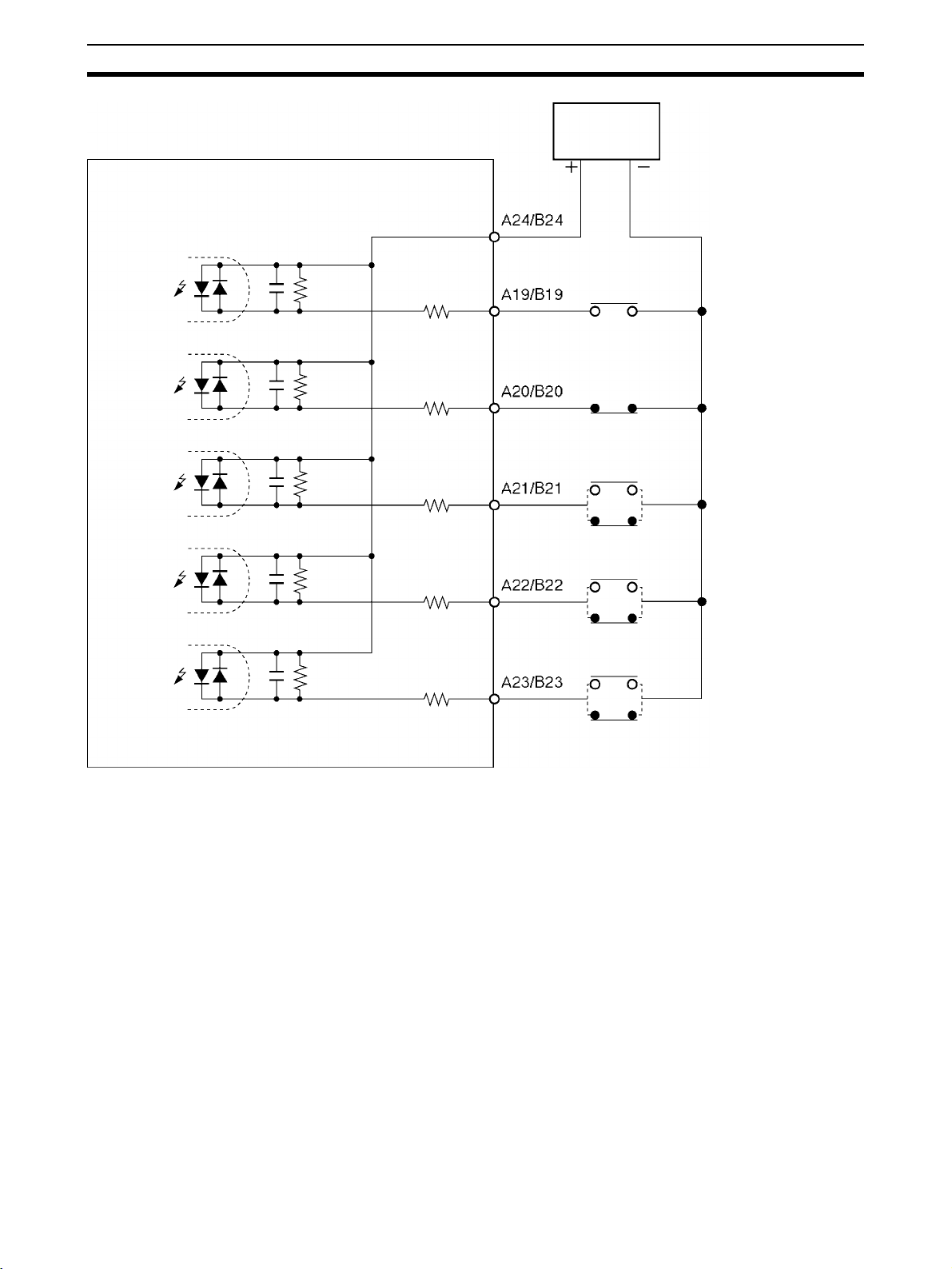
Wiring Section 3-4
24-VDC
Position Control Unit
power
supply
External
interrupt
input signal
Emergency
stop input
signal
Origin
proximity
input signal
CW limit
input signal
CCW limit
input signal
680 Ω
680 Ω
680 Ω
680 Ω
680 Ω
4.7 kΩ (1/2W)
4.7 kΩ (1/2W)
4.7 kΩ (1/2W)
4.7 kΩ (1/2W)
4.7 kΩ (1/2W)
Switch (N.O. contact)
Switch (N.C. contact)
Switch
(N.O./N.C. contact)
Switch
(N.O./N.C. contact)
Switch
(N.O./N.C. contact)
3-4-3 Connecting Origin and Positioning Completed Input Signals
The examples below show input connections when open collector sensor output and the encoder’s Z-phase line driver output are used.
Use a sensor with no chattering, such as a photoelectric sensor, for the origin
input signal.
!Caution Connect a switch with a switching capacity of at least 5 mA to the 24-V origin
input signal terminal.
!Caution Do not connect the 5-VDC origin input signal input to any output circuit except
the line driver.
!Caution Use either the 24-V origin input signal or the 5-V origin input signal, but not
both. Also, be sure not to connect them to the wrong terminal. Using both signals or connecting them to the wrong terminal will result in damage to internal
circuitry.
42
Page 68

Wiring Section 3-4
Origin Input Signal (24 V)
Position Control Unit
150 Ω
4.7 kΩ
A15/B15
24-VDC power
supply
+ –
Example:
OMRON E2R-A01 Proximity
Sensor (NPN output type)
+v
A14/B14
680 Ω
Origin Input Signal (5 V) (Line Driver Input)
Position Control Unit
4.7 kΩ
680 Ω
Positioning Completed
Input Signal
150 Ω
The positioning completed input signal is also used as an origin search completed signal in modes 2 and 3. Adjust the setting of the Servo Drive so that
A16/B16
A14/B14
this signal always turns off while the servomotor is operating, and on when the
motor is stopped.
An origin search operation cannot be completed unless the positioning completed input signal turns ON after positioning has been completed.
Signal
0 V
OMRON R88D-GT
Servo Drive
23
+z
24
–z
Switch
circuitry
Position Control Unit
680 Ω
4.7 kΩ
(1/2W)
3-4-4 Wiring Precautions
Operational errors such as dislocation can occur in most electronic control
devices if they are subjected to electronic noise from nearby power lines or
loads. Recovery from such errors is usually very difficult and time consuming.
A1/B1
A12/B12
24-VDC
power supply
+
–
INPCOM
OMRON R88D-GT
Servo Drive
39
INP
38
43
Page 69

Wiring Section 3-4
To avoid such noise-generated operational errors and improve system reliability, always observe the following precautions in wiring the system.
Be sure to use the sizes and materials indicated in the specifications when
connecting power lines and cables.
Power lines (e.g., AC power supply, motor power line) and control lines (e.g.,
pulse output lines, external I/O signal lines) must be wired separately. Never
put these lines into the same duct or make them into a single bundle.
• Attach a multi-layer ceramic capacitor of a thickness of less than 1
the pulse output power supply to improve noise resistance.
• Do not use a 24-VDC or 5-VDC power supply for pulse output in common
with the power supply for other I/O.
• Use shielded cable for control lines.
• Connect the shielded cable to the frame ground at both the PCU and the
driver.
• Attach a surge absorber to all inductive loads, such as relays, solenoids,
and solenoid valves.
DC relays AC relays
+
µF to
DC
–
Solenoids, etc.
Solenoid Surge absorber
Diode for surge
absorption
AC Surge
RYRY
absorber
Note Connect the diode and surge absorber as close as possible to the relay. Use a
diode capable of withstanding a voltage five times higher than the circuit voltage.
• Insert a noise filter into the power supply inlet if noise enters the power
line (e.g., when it is connected to the same power supply as an electric
welder or an electric spark machine or when there is any supply generating high frequency noise).
• Connect to a ground of 100
greater than 1.25 mm
2
Ω or less and use the thickest possible wire,
.
• Twisted-pair cable is recommended for power lines.
44
Page 70

Connection Examples for Different Types of Motor Driver Section 3-5
3-5 Connection Examples for Different Types of Motor Driver
This section provides examples of wiring the X and Y axes. If the Y and U
axes are also to be used, check the connector pin numbers in 3-3 External I/O
Circuitry and wire them in the same way.
Note 1. Be sure to connect a power supply for unused N.C. input terminals and turn
them on.
2. Use shielded wire for connecting to stepping motor drivers and Servo
Drives. Connect the shielded cable to an FG at both the PCU and the driver.
Example 1: Mode 0 Connection
This example shows the use of a stepping motor with an external sensor signal connected to the origin input signal.
Position Control Unit
(open collector outputs
on the CS1W-NC@13)
CW output
(with 1.6-k
resistance)
CCW output
(with 1.6-k
resistance)
24-V power supply
for output
24-V GND
for output
Origin proximity input signal
Origin Input
signal
Input common
CCW limit
input signal
CW limit input
signal
Emergency
stop input
signal
A6
A8
A1
A2
A21
A15
A14
A24
A23
A22
A20
FG
+
24 VDC
24 VDC
+
Shield
N.O. contact
0 V
24 V
Signal
N.C. contact
Example:
DFU1514W stepping motor driver, made by Oriental Motor Co.
+CW
– CW
+CCW
– CCW
FG
N.C. contact
N.C. contact
PK564AW stepping motor
OMRON E2R-A01
Proximity Sensor
(NPN-output model).
45
Page 71
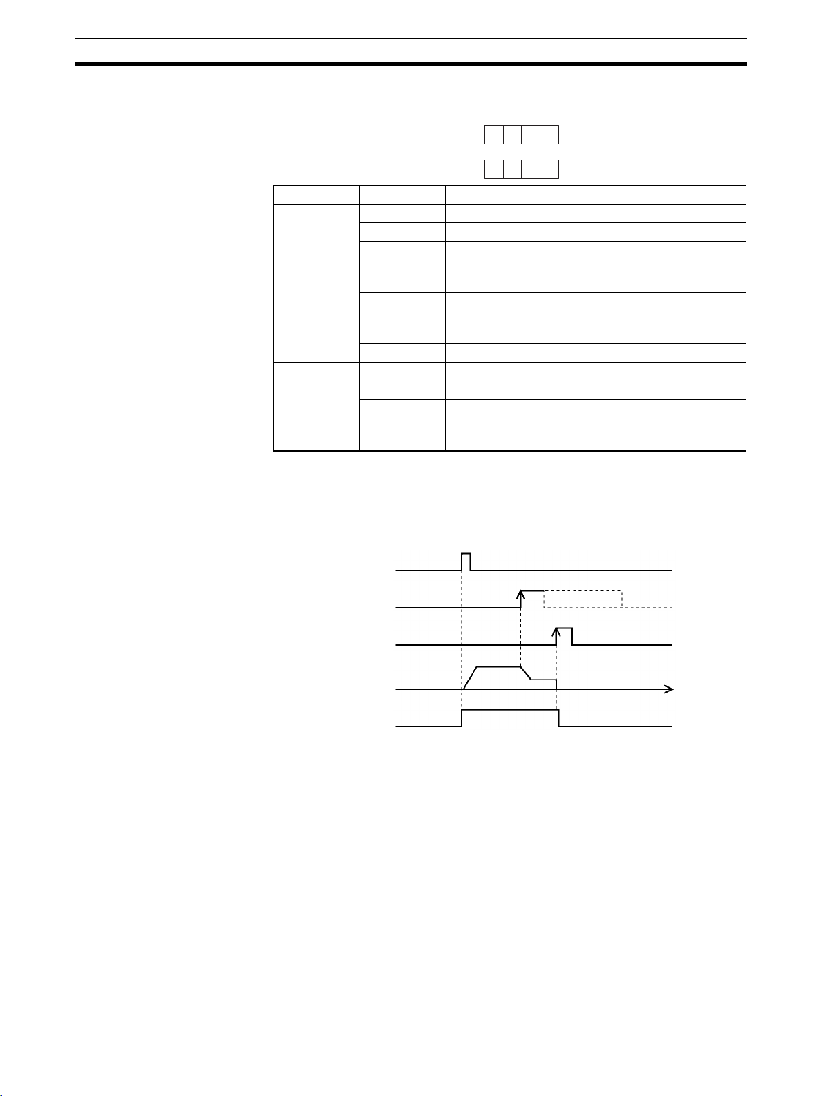
Connection Examples for Different Types of Motor Driver Section 3-5
Parameter Setting Example
15 0
0 0 6 0
m+4
0 1 0 0
m+5
Word Bits Setting Contents
m+4 00 0 CW/CCW output
01 to 03 0 ---
04 0 Limit input: N.C. contact
05 1 Origin proximity input signal: N.O.
06 1 Origin input signal: N.O. contact
07 0 Pulse output stopped with emergency
08 to 15 0 ---
m+5 00 to 03 0 Mode 0
04 to 07 0 Reverse mode 1
08 to 11 1 Takes origin input signal after origin
12 to 15 0 Search direction: CW
contact
stop input signal.
proximity input signal is received.
Note “m” is the beginning DM word allocated when the unit number is set.
Origin Search Operation
The origin search operation is completed with the rising edge of the origin
input signal after the rising edge of the origin proximity input signal.
ORIGIN
SEARCH
Origin proximity
input signal
Origin input
signal
Pulse output
Busy Flag
Time
46
Page 72

Connection Examples for Different Types of Motor Driver Section 3-5
Example 2: Mode 1 Connection
In this example, a Servo Drive is employed and the Z-phase of the encoder is
connected to the origin line driver input terminal and used as the origin input
signal. An OMRON G-Series Servo Drive is used.
Open Collector Output (CS1W-NC113/NC213/NC413)
Position Control Unit
(open collector outputs
on the CS1W-NC@13)
CW output
(with 1.6-kΩ
resistance)
CCW output
(with 1.6-k Ω
resistance)
A6
A8
Shield
OMRON R88D-GT@@@
Servo Drive
R88M-G@
3
+CW
4
−CW
5
+CCW
6
−CCW
Servomotor
24-V power
supply for
output
24-V GND f or
output
Error counter
reset output
Origin input
signal
Input common
Origin pro ximity
input signal
A1
A2
A10
A16
A14
A24
A21
+
24 VDC
FG
24 VDC
+
N.O. contact
N.O. contact
7
29
30
23
24
Shell
+24VIN
RUN
ECRST
+Z
−Z
FG
CCW limit
input signal
CW limit input
signal
Emergency stop
input signal
A23
A22
A20
N.C. contact
N.C. contact
N.C. contact
47
Page 73

Connection Examples for Different Types of Motor Driver Section 3-5
Parameter Setting Example
This example is explained in terms of the X axis. For more details, refer to 4-3
Axis Parameter Area.
15 0
0 0 E 0
m+4
0 0 0 1
m+5
Word Bits Setting Contents
m+4 00 0 CW/CCW output
01 to 03 0 ---
04 0 Limit input: N.C. contact
05 1 Origin proximity: N.O. contact
06 1 Origin input signal: N.O. contact
07 1 Pulse output stopped by emergency
08 to 15 0 ---
m+5 00 to 03 1 Mode 1
04 to 07 0 Reverse mode 1
08 to 11 0 Takes origin input signal after rising
12 to 15 0 Motor direction: CW
stop input signal; error counter reset
signal output.
and falling edge of origin proximity
signal.
Note “m” is the beginning DM word allocated when the unit number is set.
Origin Search Operation
The origin search operation stops on the rising edge of the first Z-phase signal after the origin proximity signal has turned from ON to OFF, and after
deceleration has ended.
ORIGIN SEARCH
Origin proximity
signal
Z-phase signal
Pulse output
Error counter
reset output
Approx. 20ms
Busy Flag
Time
48
Page 74

Connection Examples for Different Types of Motor Driver Section 3-5
Line Driver Output (CS1W-NC133/NC233/NC433)
Position Control Unit
(line driver outputs on
the CS1W-NC@33)
5-V GND
for pulse
output
5-V power
supply for
pulse
output
CW (+)
output
CW (–)
output
CCW (+)
output
CCW (–)
output
24-V
power
supply for
output
24-V GND
for output
A3
A4
A5
A6
A7
A8
A1
A2
+
5 VDC
+
24 VDC
Shield
N.O. contact
Example:
OMRON R88DServo Drive
3
+CW
4
−CW
5
+CCW
6
−CCW
+24VIN
7
RUN
29
GT@@@
Error
counter
reset
output
Origin
input
signal
A10
A16
A14
FG
30
23
24
Shell
ECRST
+Z
−Z
FG
49
Page 75

Connection Examples for Different Types of Motor Driver Section 3-5
Example 3: Mode 2 Connection
In this example, as in example 2, a Servo Drive is employed and the Z-phase
of the encoder is connected to the origin line driver input terminal and used as
the origin input signal. OMRON Servo Drive are used.
In contrast to mode 1, the positioning completed signal (INP) of the Servo
Drive serves as both the origin search completed and the positioning completed signals.
Set the Servo Drive so that the positioning completed signal turns OFF during
motor operation and ON while the motor is stopped.
An origin search operation cannot be completed if the positioning completed
input signal from the Servo Drive is not properly connected or set.
W-series Servo Drive (CS1W-NC113/NC213/NC413)
Position Control Unit
(open collector outputs
on the CS1W-NC@13)
CW output
(with 1.6-kΩ
resistance)
CCW output
(with 1.6-kΩ
resistance)
24-V power
supply for
output
24-V GND
for output
A6
A8
A1
A2
24
VDC
Shield
N.O. contact
OMRON R88D-WT@@@@
Servo Drive
R88M-W
Servomotor
11
12
47
40
7
8
+CW
–CW
+CCW
–CCW
+24
VIN
RUN
Error counter
reset output
Origin input
signal
Positioning
completed
input signal
Input
common
Origin
proximity
input signal
CCW limit
input signal
CW limit
input signal
Emergency
stop input
signal
A11
A16
A14
A12
A24
A21
A23
A22
A20
FG
24 VDC
+
N.O. contact
N.C. contact
N.C. contact
N.C. contact
15
14
19
20
25
26
Shell
+ECRST
–ECRST
+Z
–Z
+INP
–INP
FG
50
Page 76

Connection Examples for Different Types of Motor Driver Section 3-5
Parameter Setting Example
This example is explained in terms of the X axis. For more details, refer to 4-3
Axis Parameter Area.
15 0
0 0 E 0
m+4
0 0 0 2
m+5
Word Bits Setting Contents
m+4 00 0 CW/CCW output
01 to 03 0 ---
04 0 Limit input: N.C. contact
05 1 Origin proximity: N.O. contact
06 1 Origin input signal: N.O. contact
07 1 Pulse output stopped by emergency
08 to 15 0 ---
m+5 00 to 03 2 Mode 2
04 to 07 0 Reverse mode 1
08 to 11 0 Takes origin input signal after rising
12 to 15 0 Search direction: CW
stop input signal; error counter reset
signal output.
and falling edge of origin proximity
input signal.
Note “m” is the beginning DM word allocated when the unit number is set.
Origin Search Operation
The origin search operation stops on the rising edge of the first Z-phase signal after the origin proximity signal has turned from ON to OFF, and after
deceleration has ended. The Busy Flag turns OFF with the positioning completed input signal.
ORIGIN
SEARCH
Origin proximity
signal
Z phase signal
Pulse output
Error counter
reset output
Approx. 20ms
Busy Flag
Positioning completed
input signal
Time
51
Page 77

Connection Examples for Different Types of Motor Driver Section 3-5
G-series or U-series Servo Drive (CS1W-NC113/NC213/NC413)
Position Control Unit
(open collector outputs
on the CS1W-NC@13)
CW output
(with 1.6-kΩ
resistance)
A6
CCW output
(with 1.6-kΩ
A8
resistance)
Shield
OMRON R88D-GT@@@
Servo Drive
R88M-G
3
+CW
4
−CW
5
+CCW
6
−CCW
Servomotor
24-V power
supply for
output
24-V GND
for output
Error counter
reset output
Origin input
signal
Positioning
completed
input signal
Input
common
Origin
proximity
input signal
A1
A2
A10
A16
A14
A12
A24
A21
+
24 VDC
FG
24 VDC
+
N.O. contact
N.O. contact
+24VIN
7
RUN
29
30
ECRST
23
+Z
24
−Z
+INP
3839INPCOM
FG
Shell
52
CCW limit
input signal
CW limit
input signal
Emergency
stop input
signal
A23
A22
A20
N.C. contact
N.C. contact
N.C. contact
Page 78

Connection Examples for Different Types of Motor Driver Section 3-5
Connection to Line Driver (CS1W-NC133/NC233/NC433)
Position Control Unit
(line driver outputs on
the CS1W-NC@33)
5-V GND
for pulse
output
5-V power
supply for
pulse
output
CW (+)
output
CW (–)
output
CCW (+)
output
CCW (–)
output
24-V
power
supply for
output
24-V GND
for output
Error
counter
reset
output
Origin
input
signal
A3
A4
A5
A6
A7
A8
A1
A2
A10
A16
A14
+
5 VDC
+
24 VDC
Shield
N.O. contact
Example:
OMRON R88DServo Drive
3
+CW
4
−CW
5
+CCW
6
−CCW
+24VIN
7
RUN
29
30
ECRST
+Z
23
24
−Z
GT@@@
R88M-G@
Servomotor
Positioning
completed
input signal
A12
FG
INP
3839INPCOM
FG
Shell
53
Page 79

Connection Examples for Different Types of Motor Driver Section 3-5
SMARTSTEP2-series or U-series Servo Drive (CS1W-NC113/NC213/NC413)
Position Control Unit
(open collector outputs
on the CS1W-NC@13)
CW output
(with 1.6-kΩ
A6
resistance)
CCW output
(with 1.6-k Ω
A8
resistance)
Shield
OMRON R7D-BP@@@
Servo Drive
22
+CW
23
−CW
24
+CCW
25
−CCW
R88M-G@
Servomotor
24-V power
supply for
output
24-V GND f or
output
Error counter
reset output
Origin input
signal
Positioning
completed
input signal
A1
A2
A10
A16
A14
A12
+
24 VDC
FG
N.O. contact
+24VIN
1
RUN
2
4
ECRST
19
+Z
20
−Z
INP
13100GND
FG
Shell
54
Page 80

Connection Examples for Different Types of Motor Driver Section 3-5
Connection to Line Driver (CS1W-NC133/NC233/NC433)
Position Control Unit
(line driver outputs on
the CS1W-NC@33)
5-V GND
for pulse
output
5-V power
supply for
pulse
output
CW (+)
output
CW (–)
output
CCW (+)
output
CCW (–)
output
24-V
power
supply for
output
24-V GND
for output
Error
counter
reset
output
A3
A4
A5
A6
A7
A8
A1
A2
A10
+
5 VDC
+
24 VDC
Shield
N.O. contact
Example:
OMRON R7D-BP
Servo Drive
22
+CW
23
−CW
24
+CCW
25
−CCW
+24VIN
1
RUN
2
4
ECRST
@@@
R88M-G@
Servomotor
Origin
input
signal
Positioning
completed
input signal
A16
A14
A12
FG
+Z
19
20
−Z
INP
13100GND
FG
Shell
55
Page 81

Connection Examples for Different Types of Motor Driver Section 3-5
SMARTSTEP A-series Servo Drive (CS1W-NC113/NC213/NC413)
Position Control Unit
(open collector outputs
on the CS1W-NC@13)
CW output
(with 1.6-kΩ
resistance)
CCW output
(with 1.6-kΩ
resistance)
24-V
power
supply for
output
24-V GND
for output
Error
counter
reset
output
24-V
origin
input
signal
A6
A8
A1
A2
A11
A15
A14
+
24 VDC
Shield
Example:
OMRON R7D-AP@@@
Servo Drive
1
2
3
4
13
N.O.
contact
14
5
6
32
33
+CW
−CW
+CCW
−CCW
+24VIN
RUN
+ECRST
−ECRST
Z
ZCOM
R7M-A@
Servomotor
Positioning
completed
input signal
A12
FG
8
10
Shell
INP
0GND
FG
56
Page 82

Connection Examples for Different Types of Motor Driver Section 3-5
Connection to Line Driver (CS1W-NC133/NC233/NC433)
Position Control Unit
(line driver outputs on
the CS1W-NC@33)
5-V GND
for pulse
output
5-V power
supply for
pulse
output
CW (+)
output
CW (–)
output
CCW (+)
output
CCW (–)
output
24-V
power
supply for
output
24-V GND
for output
A3
A4
A5
A6
A7
A8
A1
A2
+
5 VDC
+
24 VDC
Shield
Example:
OMRON R7D-AP@@@
Servo Drive
1
2
3
4
N.O.
13
contact
14
+CW
−CW
+CCW
−CCW
+24VIN
RUN
R7M-A@
Servomotor
Error
counter
reset
output
24-V origin
input
signal
Positioning
completed
input
signal
A11
A15
A14
A12
FG
5
6
32
33
8
10
Shell
+ECRST
−ECRST
Z
ZCOM
INP
0GND
FG
57
Page 83

Connection of Unused Axes Section 3-6
3-6 Connection of Unused Axes
This section provides connection examples for the CS1W-NC213, CS1WNC233, CS1W-NC413, and CS1W-NC433 in applications where not all axes
are used.
3-6-1 Using Only the X Axis and Not the Y Axis on the CS1W-NC213/
NC233 (with Unit Version 2.1 or Later)
On PCUs with unit version 2.1 or later, wiring is not required for the CW/CCW
limit input signal and the emergency stop input signal for specified unused
axes.
The following figure, based on Example 2: Mode 1 Connection in 3-5 Connec-
tion Examples for Different Types of Motor Driver, shows an example of connecting external I/O when only the X axis and not the Y axis is used on the
CS1W-NC213/NC233. The limit input signal for the X axis is assumed to be
set as an N.C. connection.
Position Control Unit
Input
common
Origin
proximity
input
signal
CCW limit
input signal
CW limit
input signal
Emergency
stop input
signal
X axis (used)
Y axis
(not used; no wiring required)
X axis (used)
Y axis
(not used; no wiring required)
X axis (used)
Y axis
(not used; no wiring required)
X axis (used)
Y axis
(not used; no wiring required)
24 VDC
N.O. contact
N.C. contact
N.C. contact
N.C. contact
To set only the X axis as the axis to be used, set the number of unused axes
to 01 in Axis Parameter Designation of 4-2 Common Parameter Area.
The following table shows the relation for each Unit between the number of
unused axes and the settings.
Setting 1-axis Unit 2-axis Unit 4-axis Unit
0 All axes used. All axes used. All axes used.
1 Error 0013 occurs. Axis Y not used. Axis U not used.
2 Error 0013 occurs. Error 0013 occurs. Axes Z and U not used.
3 Error 0013 occurs. Error 0013 occurs. Axes Y, Z, and U not used.
58
Making this setting eliminates the need to perform wiring for the Y axis.
If other parameters are used in their default settings, the CW/CCW limit input
signal will be set to a N.C. contact input. Therefore, current will flow for the signal when the power supply for the inputs is connected.
Page 84

Servo Relay Unit Section 3-7
3-6-2 CS1W-NC213/NC233 – X Axis Only (Unit Versions Earlier Than
2.1)
On PCUs with a unit version earlier than 2.1, unused axes require only the
emergency stop input signal to be wired.
Based on Example 2: Mode 1 Connection on page 47, the following example
shows the connections for the CS1W-NC213/NC233 when only the X axis
(and not the Y axis) is used. In this example, the limit input signals for both
axes are set to N.C. contacts. With the CS1W-NC413/NC433, if the Z axis is
used and the U axis is not used, the connection will be the same with X and Y
replaced by Z and U respectively.
Position Control Unit
Input
common
Origin
proximity
input
signal
CCW limit
input signal
CW limit
input signal
Emergency
stop input
signal
X axis (used)
Y axis
(not used; no wiring required)
X axis (used)
Y axis (not used)
X axis (used)
Y axis (not used)
X axis (used)
Y axis (not used)
24 VDC
N.O. contact
N.C. contact
N.C. contact
N.C. contact
When there is an unused axis, connect the emergency stop input signal (N.C.
contact) and the CW/CCW limit input signals (N.C./N.O. switchable) for that
axis so that they are ON. If the parameters are at their default settings, the
CW/CCW limit input signals are N.C. contact inputs and so connect an input
power supply and keep power ON.
If the emergency stop input signal and the CW/CCW limit input signals for an
unused axis are not ON, a sensor input error (error codes 6000, 6100, or
6101) will be generated for the axis, and the ERC and SENS indicators as
well as the LED indicator for the axis will light or flash. The used axis, however, will continue to operate normally even if an error is generated for the
unused axis.
Note If the CW/CCW limit input signals for the unused axis are set to N.O contacts
using the parameter settings, it is not necessary to wire the CW/CCW limit
inputs. For details, refer to 4-3 Axis Parameter Area.
3-7 Servo Relay Unit
• Wiring requirements can be reduced by connecting Servo Drives and
PCUs via a Servo Relay Unit, which provide a connector and a terminal
block in one Unit.
59
Page 85

Servo Relay Unit Section 3-7
• The connecting cable and the type of Servo Relay Unit required will
depend on the Servo Drive model connected. Refer to the tables under
Connection Compatibility given below.
Connections Diagram
Position Control Unit
CS1W-NC113
CS1W-NC213
CS1W-NC413
CS1W-NC133
CS1W-NC233
CS1W-NC433
XW2Z-@@@J-A@
Connecting Cable
XW2Z-@@@J-B@
Connecting Cable
XW2B-@@J6-@
Servo Relay Unit
Servo Drive
R88D-UP@@@
R88D-UT@@@
R88D-WT@@@@
R88D-GT@@@
R7D-AP@@@
R7D-ZP@@@
R7D-BP@@@
Connection Compatibility
CS1W-NC113/NC213/NC413
PCU Cable connected to
CS1W-NC113 XW2Z-@@@J-A6 XW2B-20J6-1B XW2Z-@@@J-B1 R88D-UP@@@
XW2Z-@@@J-A8 XW2B-20J6-1B XW2Z-@@@J-B5 R7D-AP@@@
CS1W-NC213
CS1W-NC413
XW2Z-@@@J-A7 XW2B-40J6-2B XW2Z-@@@J-B1 R88D-UP@@@
XW2Z-@@@J-A9 XW2B-40J6-2B XW2Z-@@@J-B5 R7D-AP@@@
XW2Z-@@@J-A9 XW2B-40J6-4A XW2Z-@@@J-B7 R7D-AP@@@
PCU
Servo Relay Unit Cable connected to
Servo Relay Unit
XW2Z-@@@J-B4 R88D-UT@@@
XW2Z-@@@J-B25 R88D-GT@@@
XW2Z-@@@J-B29 R7D-BP@@@
XW2Z-@@@J-B17 R7D-ZP@@@
XW2Z-@@@J-B4 R88D-UT@@@
XW2Z-@@@J-B25 R88D-GT@@@
XW2Z-@@@J-B29 R7D-BP@@@
XW2Z-@@@J-B17 R7D-ZP@@@
Servo Drive
R88D-WT@@@@
R88D-WT@@@@
(when using RS-422)
60
Page 86

Servo Relay Unit Section 3-7
CS1W-NC133/NC233/NC433
PCU Cable connected to
CS1W-NC133 XW2Z-@@@J-A10 XW2B-20J6-1B XW2Z-@@@J-B1 R88D-UP@@@
XW2Z-@@@J-A12 XW2B-20J6-1B XW2Z-@@@J-B5 R7D-AP@@@
CS1W-NC233
CS1W-NC433
XW2Z-@@@J-A11 XW2B-40J6-2B XW2Z-@@@J-B1 R88D-UP@@@
XW2Z-@@@J-A13 XW2B-40J6-2B XW2Z-@@@J-B5 R7D-AP@@@
XW2Z-@@@J-A13 XW2B-40J6-4A XW2Z-@@@J-B7 R7D-AP@@@
PCU
• The cable length for PCU Connecting Cables is indicated in the “@@@”.
050: 0.5 m
100: 1 m
• The cable length for Servo Drive Connecting Cables is indicated in the
“@@@”.
100: 1 m
200: 2 m
• When using the CS1W-NC413/433, 2 Servo Relay Units and 2 PCU Connecting Cables are required.
• When using in combination with the CS1W-NC213/NC233 (2-axis control), 2 Servo Drive Connecting Cables are required.
• When using in combination with the CS1W-NC413/NC433 (4-axis control), 4 Servo Drive Connecting Cables are required.
Servo Relay Unit Cable connected to
Servo Relay Unit
XW2Z-@@@J-B4 R88D-UT@@@
XW2Z-@@@J-B25 R88D-GT@@@
XW2Z-@@@J-B29 R7D-BP@@@
XW2Z-@@@J-B17 R7D-ZP@@@
XW2Z-@@@J-B4 R88D-UT@@@
XW2Z-@@@J-B25 R88D-GT@@@
XW2Z-@@@J-B29 R7D-BP@@@
XW2Z-@@@J-B17 R7D-ZP@@@
Servo Drive
R88D-WT@@@@
R88D-WT@@@@
(when using RS-422)
61
Page 87

Servo Relay Unit Section 3-7
62
Page 88

SECTION 4
Data Areas
This section provides an overview of the parameter and data settings used in Position Control Unit operation and provides
information on memory allocation.
4-1 Overall Structure . . . . . . . . . . . . . . . . . . . . . . . . . . . . . . . . . . . . . . . . . . . . . . . 64
4-1-1 Data Areas . . . . . . . . . . . . . . . . . . . . . . . . . . . . . . . . . . . . . . . . . . . . 66
4-2 Common Parameter Area . . . . . . . . . . . . . . . . . . . . . . . . . . . . . . . . . . . . . . . . 69
4-2-1 Outline . . . . . . . . . . . . . . . . . . . . . . . . . . . . . . . . . . . . . . . . . . . . . . . 70
4-2-2 Details . . . . . . . . . . . . . . . . . . . . . . . . . . . . . . . . . . . . . . . . . . . . . . . . 70
4-3 Axis Parameter Area . . . . . . . . . . . . . . . . . . . . . . . . . . . . . . . . . . . . . . . . . . . . 74
4-3-1 Outline . . . . . . . . . . . . . . . . . . . . . . . . . . . . . . . . . . . . . . . . . . . . . . . 74
4-3-2 Details . . . . . . . . . . . . . . . . . . . . . . . . . . . . . . . . . . . . . . . . . . . . . . . . 77
4-3-3 Operation Modes . . . . . . . . . . . . . . . . . . . . . . . . . . . . . . . . . . . . . . . 80
4-4 Operating Memory Area . . . . . . . . . . . . . . . . . . . . . . . . . . . . . . . . . . . . . . . . . 93
4-4-1 Outline . . . . . . . . . . . . . . . . . . . . . . . . . . . . . . . . . . . . . . . . . . . . . . . 93
4-5 Operating Data Area . . . . . . . . . . . . . . . . . . . . . . . . . . . . . . . . . . . . . . . . . . . . 97
4-5-1 Outline . . . . . . . . . . . . . . . . . . . . . . . . . . . . . . . . . . . . . . . . . . . . . . . 97
4-6 Memory Operation Data . . . . . . . . . . . . . . . . . . . . . . . . . . . . . . . . . . . . . . . . . 100
4-6-1 Outline . . . . . . . . . . . . . . . . . . . . . . . . . . . . . . . . . . . . . . . . . . . . . . . 100
4-7 Zone Data Area . . . . . . . . . . . . . . . . . . . . . . . . . . . . . . . . . . . . . . . . . . . . . . . . 103
4-7-1 Zone Function. . . . . . . . . . . . . . . . . . . . . . . . . . . . . . . . . . . . . . . . . . 103
4-7-2 Zone Data Settings . . . . . . . . . . . . . . . . . . . . . . . . . . . . . . . . . . . . . . 104
4-8 Examples of Parameter Settings . . . . . . . . . . . . . . . . . . . . . . . . . . . . . . . . . . . 104
4-8-1 Setting Positioning Using Two Axes . . . . . . . . . . . . . . . . . . . . . . . . 104
4-8-2 Setting Positioning Using One Axis. . . . . . . . . . . . . . . . . . . . . . . . . 106
4-8-3 Setting for Continuous Operation in the Same Direction for One Axis 108
63
Page 89

Overall Structure Section 4-1
4-1 Overall Structure
The PCU is used by exchanging data with the CPU Unit as shown below.
CPU Unit
CIO Area
PCU
Special I/O Unit Area
Operating memory area
(output)
(input)
DM or EM Area
User-specified DM or EM words
(specified in common parameters)
Operating data area
(output)
(input)
DM Area words allocated
to Special I/O Units
Common parameter area
Axis parameter area
User-specified DM or EM words
(for data transfer)
Data transfer area
CX-Position
I/O refresh
Power up
or restart
(See note 1.)
Data transfer
Operating commands
Status (flags)
Operating data
Status data
Common parameters
Axis parameters
Memory operation data
Positioning
sequences
Speeds
Positions
Acceleration times
Deceleration times
Dwell times
Zones
Save data
Commands
Settings
Operating data
Result
Flash memory
Command
execution
64
PCU's internal memory
Note The user can select by means of a common parameters setting whether the
axis parameters set in the CPU Unit’s DM Area are to be transferred to the
PCU for use, or whether the axis parameters saved in the PCU’s flash memory are to be used.
Page 90

Overall Structure Section 4-1
The data handled by the PCU can be classified in the way shown below.
Data name Contents Setting area Enable timing
Common parameter area
(Refer to 4-2 Common
Parameter Area.)
Axis parameter area
(Refer to 4-3 Axis Param-
eter Area.)
Operating memory area
(Refer to 4-4 Operating
Memory Area.)
Operating data area
(Refer to 4-5 Operating
Data Area.)
Memory operation data
(Refer to 4-6 Memory
Operation Data.)
Zone data
(Refer to 4-7 Zone Data
Area.)
This area contains the parameters for
settings related to basic PCU operation,
such as allocation of the operating memory area.
The common parameters must be set
when using the PCU.
This area contains the parameters for
settings related to axis operation, such
as pulse output type, logic for input signals, operation modes, and maximum
speed values.
Outputs for controlling PCU operation,
such as for direct operation, memory
operation, jogging, and origin search, are
allocated to this area. Information (see
note) relating to the status of the PCU,
such as busy flags, error flags, and external input are input to this area.
This area is for settings such as positions, speeds, and acceleration/deceleration times for direct operation, origin
searches and jogging, as well as positioning sequence numbers for memory
operation. It also contains PCU status
data (see note), such as present positions and the number of the currently
executed positioning sequence.
This area is for settings related to memory operation, such as operation
sequences, positions, speeds, and acceleration/deceleration times. The memory
operation area contains the following six
types of data:
• Positioning sequences
• Speeds
• Positions
• Acceleration times
• Deceleration times
• Dwell times
This data determines zones for the
present positions of axes controlled by
the PCU.
DM Area words in the
CPU Unit allocated to
Special I/O Units
DM Area words in the
CPU Unit allocated to
Special I/O Units
PCU’s flash memory
(See note on previous
page.)
CPU Unit’s Special I/O
Unit Area
CPU Unit’s DM or EM
area (determined by
common parameter setting)
PCU’s internal memory
(can be saved to PCU’s
flash memory)
PCU’s internal memory
(can be saved to PCU’s
flash memory)
The settings are transferred from the CPU Unit
to the PCU at power up
or restart and enabled.
These settings are transferred from the CPU
Unit’s DM Area or the
PCU’s flash memory to
the PCU’s internal memory at power up or
restart and enabled.
Operating commands
are sent from the CPU
Unit to the PCU and status data is sent from the
PCU to the CPU Unit
with every I/O refresh.
Data is updated with
every I/O refresh. The
set data is enabled and
used with the startup of
each operation.
Data is read from the
PCU’s flash memory to
the internal memory at
power up or restart. Settings are updated when
data is transferred. The
set data is enabled and
used with the startup of
each memory operation.
Data is read from the
PCU’s flash memory to
the internal memory at
power up or restart. Settings are updated when
data is transferred.
Note Error codes are input to the operating memory area.
Using these settings, the PCU executes operation (1) using the data/parameter areas specified in the common parameters and axis parameters (2)
according to the operating commands received from the operating memory
area and (3) based on operating data, memory operation data, and zone data.
The common parameters and axis parameters are basic settings for the PCU
and the axes to be controlled. It is necessary to make these settings when
using the PCU. Make settings for operating data, memory operation data, and
zone data according to the kind of operation required.
65
Page 91

Overall Structure Section 4-1
4-1-1 Data Areas
The following tables give the addresses (bit/word addresses in the CPU Unit
and addresses in the PCU’s internal memory) for the parameters and data
handled by the PCU. For more details, refer to the relevant sections.
Note Do not write to unused areas in parameters and data. Doing so may cause,
malfunctions.
Common Parameter Area (refer to page 69)
Beginning word of common parameter area, m = D20000 + 100 × unit number.
Word (same for all models) Name Data size
m Operating data area designation 1 word
m+1 Beginning word of operating data area 1 word
m+2 Axis parameter designation 1 word
m+3 Not used 1 word
Axis Parameter Area (refer to page 74)
Word (address in PCU) Name Data size
X axis Y axis Z axis U axis
m+4 (0004) m+32 (0020) m+60 (003C) m+88 (0058) I/O settings 1 word
m+5 (0005) m+33 (0021) m+61 (003D) m+89 (0059) Operation mode selection 1 word
m+6 (0006) m+34 (0022) m+62 (003E) m+90 (005A) Maximum speed 2 words
m+8 (0008) m+36 (0024) m+64 (0040) m+92 (005C) Initial speed 2 words
m+10 (000A) m+38 (0026) m+66 (0042) m+94 (005E) Origin search high speed 2 words
m+12 (000C) m+40 (0028) m+68 (0044) m+96 (0060) Origin search proximity speed 2 words
m+14 (000E) m+42 (002A) m+70 (0046) m+98 (0062) Origin compensation 2 words
m+16 (0010) m+44 (002C) m+72 (0048) m+100 (0064) Backlash compensation 1 word
m+17 (0011) m+45 (002D) m+73 (0049) m+101 (0065) Backlash compensation speed 2 words
m+19 (0013) m+47 (002F) m+75 (004B) m+103 (0067) Acceleration/Deceleration curves, accel-
eration/deceleration time designations
m+20 (0014) m+48 (0030) m+76 (004C) m+104 (0068) Origin search acceleration time 2 words
m+22 (0016) m+50 (0032) m+78 (004E) m+106 (006A) Origin search deceleration time 2 words
m+24 (0018) m+52 (0034) m+80 (0050) m+108 (006C) Positioning monitor time 2 words
m+25 (0019) m+53 (0035) m+81 (0051) m+109 (006D) CCW software limit 2 words
m+27 (001B) m+55 (0037) m+83 (0053) m+111 (006F) CW software limit 2 words
m+31 (001F) m+59 (003B) m+87 (0057) m+115 (0073) Initial pulse designation 1 word
1 word
66
Page 92

Overall Structure Section 4-1
Operating Memory Area (refer to page 93)
Beginning word of operating memory area, n = 2000 + 100 × unit number.
Words Bits Operation
1 axis 2 axes 4 axes
X axis X axis Y axis X axis Y axis Z axis U axis
n n n+2 n n+2 n+4 n+6 00 Sequence Number Enable
01 START
02 INDEPENDENT START
03 ABSOLUTE MOVEMENT
04 RELATIVE MOVEMENT
05 INTERRUPT FEEDING
06 ORIGIN SEARCH
07 ORIGIN RETURN
08 PRESENT POSITION PRESET
09 JOG
10 Direction designation
11 TEACH
12 RELEASE PROHIBIT/ERROR RESET
13 Error counter reset output/origin-adjustment command
output
14 Override Enable
15 STOP
n+1 n+1 n+3 n+1 n+3 n+5 n+7 00 to 07Not used
08 FORCED INTERRUPT
09 to 11Not used
12 WRITE DATA
13 READ DATA
14 SAVE DATA
15 Not used
n+2 n+4 n+7 n+8 n+11 n+14 n+17 00 to 03Not used
04 Waiting For Memory Operation Flag
05 Positioning Completed Flag
06 No Origin Flag
07 Origin Stop Flag
08 Zone 0 Monitor Flag
09 Zone 1 Monitor Flag
10 Zone 2 Monitor Flag
11 Teaching Completed Flag
12 Error Flag
13 Busy Flag
14 Data Transferring Flag
15 Deceleration Stop Execution Flag
67
Page 93

Overall Structure Section 4-1
Words Bits Operation
1 axis 2 axes 4 axes
X axis X axis Y axis X axis Y axis Z axis U axis
n+3 n+5 n+8 n+9 n+12 n+15 n+18 00 to 07Not used
08 CW limit input signal
09 CCW limit input signal
10 Origin proximity input signal
11 Origin input signal
12 Interrupt input signal
13 Emergency stop input signal
14 Positioning completed signal
15 Error counter reset output/origin-adjustment command
output
n+4 n+6 n+9 n+10 n+13 n+16 n+19 00 to 15Error code
Operating Data Area (refer to page 97)
Beginning word of operating data area, I = word specified in common parameters (m, m+1).
Words Name Data size
1 axis 2 axes 4 axes
X axis X axis Y axis X axis Y axis Z axis U axis
I I I Number of write
words
I+1 I+1 I+1 Write source area 1 word
I+2 I+2 I+2 Write source word 1 word
I+3 I+3 I+3 Write destination
address
I+4 I+4 I+4 Number of read
words
I+5 I+5 I+5 Read source
address
I+6 I+6 I+6 Read destination
area
I+7 I+7 I+7 Read destination
word
I+8 I+8 I+20 I+8 I+20 I+32 I+44 Position 2 words
I+10 I+10 I+22 I+10 I+22 I+34 I+46 Speed 2 words
I+12 I+12 I+24 I+12 I+24 I+36 I+48 Acceleration time 2 words
I+14 I+14 I+26 I+14 I+26 I+38 I+50 Deceleration time 2 words
I+16 I+16 I+28 I+16 I+28 I+40 I+52 Positioning
sequence
I+17 I+17 I+29 I+17 I+29 I+41 I+53 Override 1 word
I+18 I+18 I+30 I+18 I+30 I+42 I+54 Teaching address 1 word
I+19 I+19 I+31 I+19 I+31 I+43 I+55 Not used 1 word
I+20 I+32 I+36 I+56 I+60 I+64 I+68 Present position 2 words
I+22 I+34 I+38 I+58 I+62 I+66 I+70 Positioning
sequence
I+23 I+35 I+39 I+59 I+63 I+67 I+71 Output code 1 word
1 word
1 word
1 word
1 word
1 word
1 word
1 word
1 word
68
Page 94

Common Parameter Area Section 4-2
Memory Operation Data (refer to page 100)
PCU internal address Name Data size
X axis Y axis Z axis U axis
1000 2000 3000 4000 Positioning
sequence numbers 0 to 99
112C 212C 312C 412C Speed numbers 0
to 99
11F4 21F4 31F4 41F4 Position numbers
0 to 99
12BE 22BE 32BE 42BE Acceleration time
numbers 1 to 9
12D2 22D2 32D2 42D2 Deceleration time
numbers 1 to 9
12E5 22E5 32E5 42E5 Dwell time num-
bers 1 to 19
Zone Data Area (refer to page 103)
PCU internal address Name Data size
X axis Y axis Z axis U axis
12F8 22F8 32F8 42F8 Zone 0, CCW 2 words
12FA 22FA 32FA 42FA Zone 0, CW 2 words
12FC 22FC 32FC 42FC Zone 1, CCW 2 words
12FE 22FE 32FE 42FE Zone 1, CW 2 words
1300 2300 3300 4300 Zone 2, CCW 2 words
1302 2302 3302 4302 Zone 2, CW 2 words
3 words
2 words
2 words
2 words
2 words
1 word
4-2 Common Parameter Area
The common parameter settings determine the areas used to set the operating data (the operating data area) and axis parameters (the axis parameter
area) required for axis control. The common parameters must be set before
using the PCU.
69
Page 95

Common Parameter Area Section 4-2
4-2-1 Outline
Memory from the area allocated to Special I/O Units in the CPU Unit’s DM
Area is allocated to the common parameters. The beginning word of the allocated area is determined by the unit number set for the PCU according to the
following equation.
Beginning word of common parameter area, m = D20000 + 100
ber.
After the common parameter settings have been made, they will go into effect
the next time the PCU is powered up or restarted.
The settings for the common parameters are explained below.
× unit num-
Word
(same for all models)
m Operating data area designation Designate the memory area to which the
m+1 Beginning word of operating data area Designate the beginning word of the
m+2 Axis parameter designation Designate the location of the data to be
m+3 Not used This area is not used. Leave set to 0000. 72
Name Configuration/Explanation Page
70
operating data is to be set. Select one
from the following.
0000: DM Area words allocated to Special I/O Units (fixed)
000D: User-specified DM Area words
0X0E: User-specified EM Area words (X:
bank number)
operating data area. If 000D (user-specified DM Area words) or 0X0E (user-specified EM Area words) is set for the
operating data area designation, specify
the beginning word of the area to be allocated as the operating data area in hexadecimal.
70
used as axis parameters. Select one from
the following.
• Axis parameter data saved in the
PCU’s flash memory.
• Axis parameter data set in the CPU
Unit’s DM Area.
• PCU’s default setting.
• Settings for unused axes (supported
on PCUs with unit version 2.1 or later).
4-2-2 Details
The details of the common parameters settings are given below.
Designation and Beginning Word of Operating Data Area
Word Address and Enable
Timing
Bit Configuration The bit configurations for the word addresses in the above table are shown
70
The word addresses and enable timing for the beginning word of operating
data area and operating data area designation settings are shown below.
Word Name Enable tim ing
NC1@3 NC2@3 NC4@3
m Operating data area des-
ignation
m+1 Beginning word of oper-
ating data area
At power up or restart
below.
Page 96

Common Parameter Area Section 4-2
15 0008 07
m
m+1
Settings The following settings are available.
Word m: 0000, 000D, 0X0E (X = 0 to 9, A, B, or C)
Word m+1: 0000 to 7FXX Hex (settings possible for “XX” will depend on
Explanation The meanings of each of the settings are given below.
Area Designation (Word m, Bits 00 to 07)
Designate the area in CPU Unit memory to be used for setting operating data.
The following settings are available.
00: DM Area Words Allocated to Special I/O Units
Memory from the area allocated to Special I/O Units in the CPU Unit’s DM
Area will be allocated according to the unit number set for the PCU. The following words will be allocated consecutively to common parameters and axis
parameters.
NC1@3: m+32 to m+55
NC2@3: m+60 to m+99
NC4@3: m+116 to m+187
0D: User-specified DM Area Words
Words within the DM Area starting from the beginning word specified in word
m+1 will be allocated.
0E: User-specified EM Area Words
Words within the EM Area starting from the beginning word specified in word
m+1 will be allocated. Specify the bank number in the bank designation setting (word m, bits 08 to 15).
Bank designation Area designation
Beginning word of operating data area (Hex)
the model)
Bank Designation (Word m, Bits 08 to 15)
If user-specified EM Area words (0E) are designated as the location for the
operating data area using the area designation setting (word m, bits 00 to 07),
use this setting to designate a bank number. The following bank numbers can
be designated: 0 (00) to 9 (09), A (0A), B (0B), C (0C). Do not, however, select
a bank that is being used as PLC file memory. If the DM Area words allocated
to Special I/O Units (00) or user-specified DM Area words (0D) are designated as the location of the operating memory area, set the bank designation
to 0 (00). Any other setting will result in an operating data area specification
error (error code 0010).
Note Do not set a bank number for a bank that is being used as PLC file memory. If
a bank that is being used as PLC file memory is set, the operating data area
settings will not be reflected in PCU operation and this will result in malfunction. When there are several PCUs mounted to the same PLC, be sure to set
the operating data areas for the PCUs so that they do not overlap with each
other. The PCU will not detect an error if operating data areas overlap, and
this may result in malfunction.
For details on the EM Area banks and how to use them as PLC file memory,
refer to the SYSMAC CS/CJ Series Programmable Controllers Programming
Manual (W394).
71
Page 97

Common Parameter Area Section 4-2
Beginning Word of Operating Data Area (Word m+1)
If user-specified DM Area words (0D) or user-specified EM Area words (0E)
are designated as the location for the operating data area using the area designation setting (word m, bits 00 to 07), use this setting to designate the
beginning word of the operating data area. The beginning word is set in hexadecimal. The following settings are possible (varies with the model):
NC1@3: 0000 to 7FE8 Hex (0 to 32744)
NC2@3: 0000 to 7FD8 Hex (0 to 32728)
NC4@3: 0000 to 7FB8 Hex (0 to 32696)
If DM Area words allocated to Special I/O Units (00) are designated as the
location for the operating data area, this setting will not be used.
Example 1
0m0 0 D
1
m+1
The area in the CPU Unit’s DM Area beginning with word 1F40 Hex (8000) is
designated as the operating data area. The following words are allocated (varies with the model):
NC1@3:D8000 to D8023
NC2@3:D8000 to D8039
NC4@3:D8000 to D8071
F 4 0
Example 2
0m2 0 E
m+1
3
9 8
A
The area in bank 2 of the CPU Unit’s EM Area beginning with word 3A98 Hex
(15000) is designated as the operating data area. The following words are
allocated (varies with the model):
NC1@3: E2_15000 to E2_15023
NC2@3: E2_15000 to E2_15039
NC4@3: E2_15000 to E2_15071
Axis Parameter Designation
Word Address and Enable
Timing
Bit Configuration The bit configuration for the word address in the above table is shown below.
The word address and enable timing for the axis parameter designation setting is shown below.
Word Name Enable tim ing
NC1@3 NC2@3 NC4@3
m+2 Axis parameter designa-
15 0008 07
Specified unused axes
m+2
12 11
Axis designation Parameter designation
tion
At power up or restart
Settings The following settings are available.
Word m+2: 0X00, 0X01 (X = 0 to 9, A to F)
Explanation The meanings of each of the settings are given below.
Parameter Designation (Word m+2, Bits 00 to 07)
Specify the axis parameters to use during PCU operation. The following settings are available.
72
Page 98

Common Parameter Area Section 4-2
00: The PCU will operate according to the axis parameters saved in the
PCU’s flash memory.
01: The PCU will operate according to the axis parameters set in the DM
Area words allocated to Special I/O Units (m+4 onwards).
Axis Designation (Word m+2, Bits 08 to 11)
If DM Area words allocated to Special I/O Units (01) are designated as the
location of axis parameters in the parameter designation setting (bits 00 to
07), use this setting to designate the axes to be set from the DM Area.
11 10 09 08
U axis
designation
Z axis
designation
Y axis
designation
X axis
designation
On PCUs with unit version 2.1 or later, setting is not required for axes specified as unused in the unused axis setting.
The meanings of the individual axis settings are as follows:
0: The axis parameter settings in the DM Area words allocated to Special
I/O Units will be used.
1: The default axis parameter settings will be used. The settings in the
DM Area words allocated to Special I/O Units will not be used.
If the PCU’s flash memory (00) is designated as the location of the axis
parameters in the parameter designation setting, the above settings will not
be used.
When using a 1-axis or 2-axis PCU, set 0 for the other axes (i.e., those not
controlled by the PCU). Setting to a value other than 0 will result in a parameter designation error (error code 0013).
Note The settings in the DM Area words allocated to Special I/O Units will not be
used for any axes that are set to 1. This means that when control is not
required for all axes (e.g., when a 4-axis PCU is used to control 3 axes), if
uncontrolled axes are set to 1, there is no need to make settings for those
axes in the DM Area.
Specified Unused Axes (Word m+2, Bits 12 to 15; Supported for Unit
Version 2.1 or Later)
This parameter is used to specify unused axes. Parameter setting and wiring
(e.g., CW, CCW, and emergency stop) are not required for the specified
unused axes.
Setting 1-axis Unit 2-axis Unit 4-axis Unit
00 All axes used. All axes used. All axes used.
01 Error 0013 occurs. Axis Y not used. Axis U not used.
02 Error 0013 occurs. Error 0013 occurs. Axes Z and U not used.
03 Error 0013 occurs. Error 0013 occurs. Axes Y, Z, and U not used.
Example 1
0 0 0 0m+2
The PCU will operate according to the axis parameters saved in the PCU’s
flash memory.
Example 2
0 A 0 1m+2
(when using a 4-axis PCU)
73
Page 99

Axis Parameter Area Section 4-3
Operation for the X and Z axes will be performed according to the axis parameters set in the following DM Area words allocated to Special I/O Units.
X-axis parameter area: words m+4 to m+31
Z-axis parameter area: words m+60 to m+87
The default settings will be used for the Y and U axes.
4-3 Axis Parameter Area
The axis parameters are used for settings that include the pulse output type,
input signal logic, and operation modes for axes subject to PCU control.
4-3-1 Outline
The axis parameter settings used will be selected from the following, according to the common parameter settings.
• The axis parameters saved in the PCU’s non-volatile (flash) memory
(when 00 is set for the parameter designation (word m+2, bits 00 to 07) in
the common parameters)
• The axis parameters set in the DM Area words allocated to Special I/O
Units
(for axes for which the axis specification (word m+2, bits 08 to 11) is set to
0 when 01 is set for the parameter designation (m+2, bits 00 to 07) in the
common parameters)
• The default axis parameters
(for axes for which the axis specification (word m+2, bits 08 to 11) is set to
1 when 01 is set for the parameter designation (m+2, bits 00 to 07) in the
common parameters)
The axis parameters are read into the PCU’s internal memory at power up or
restart. Also, by using data transfer, changes in the axis parameters other
than the I/O settings and the operation mode can be reflected in subsequent
operating commands.
When the axis parameters are set from the DM Area words allocated to Special I/O Units, the setting area (i.e., the axis parameter area) will follow on from
the area used for the common parameters. The beginning word will depend
on the unit number set for the PCU in the way shown below.
Beginning word of axis parameter area = m+4 (where m = D20000 + 100
unit number)
The following tables list the data set by the axis parameters. The tables give
the memory allocations for when the axis parameters in the DM Area words
allocated to Special I/O Units are used as well as the addresses in the PCU’s
internal memory used for data transfer. For details on data transfer, refer to
SECTION 5 Transferring and Saving Data. The DM Area word allocations and
the PCU’s internal memory addresses are the same for all models. There are,
×
74
Page 100

Axis Parameter Area Section 4-3
however, no Y, Z, or U-axis parameters when using 1-axis PCUs, and no Z or
U-axis parameters when using 2-axis PCUs.
Word
(PCU internal address)
NC1@3 NC2@3 NC4@3
X axis Y axis Z axis U axis
m+4
(0004)
m+5
(0005)
m+6
(0006)
m+7
(0007)
m+8
(0008)
m+9
(0009)
m+10
(000A)
m+11
(000B)
m+12
(000C)
m+13
(000D)
m+14
(000E)
m+15
(000F)
m+16
(0010)
m+17
(0011)
m+18
(0012)
m+32
(0020)
m+33
(0021)
m+34
(0022)
m+35
(0023)
m+36
(0024)
m+37
(0025)
m+38
(0026)
m+39
(0027)
m+40
(0028)
m+41
(0029)
m+42
(002A)
m+43
(002B)
m+44
(002C)
m+45
(002D)
m+46
(002E)
m+60
(003C)
m+61
(003D)
m+62
(003E)
m+63
(003F)
m+64
(0040)
m+65
(0041)
m+66
(0042)
m+67
(0043)
m+68
(0044)
m+69
(0045)
m+70
(0046)
m+71
(0047)
m+72
(0048)
m+73
(0049)
m+74
(004A)
m+88
(0058)
m+89
(0059)
m+90
(004A)
m+91
(005B)
m+92
(005C)
m+93
(005D)
m+94
(005E)
m+95
(005F)
m+96
(0060)
m+97
(0061)
m+98
(0062)
m+99
(0063)
m+100
(0064)
m+101
(0065)
m+102
(0066)
Name Configuration/Explanation Page
I/O settings Specifies the following items
related to I/O:
• Output pulse selection
(CW/CCW output, pulse/
direction output)
• Contact types (N.O./N.C.)
for limit input signal, origin
proximity input signal, and
origin input signal
• Error counter reset output
control when emergency
stop signal is input
• Origin undefined designation when emergency stop
signal or limit signal is
input
Operation mode selection Sets the operation mode
Maximum speed (rightmost word)
(leftmost word)
Initial speed (rightmost word)
(leftmost word)
Origin search high
speed
Origin search
proximity speed
Origin compensation value
Backlash compensation Specifies the number of
Backlash compensation speed
(rightmost word)
(leftmost word)
(rightmost word)
(leftmost word)
(rightmost word)
(leftmost word)
(rightmost word)
(leftmost word)
used for the motor driver and
specifies the origin detection
method.
Specifies the maximum
speed for each of the axes.
Specifies the initial speed for
each of the axes.
Specifies the origin search
high speed for each of the
axes.
Specifies the origin search
proximity speed for each of
the axes.
Specifies the amount of compensation after the origin
input signal is detected by an
origin search operation.
pulses output for backlash
compensation.
Specifies the speed for outputting the backlash compensation.
77
79
82
83
83
84
84
85
86
75
 Loading...