

Page 1

Cat. No. W342-E1-14
SYSMAC CS/CJ/CP Series
SYSMAC One NSJ Series
Communications Commands
REFERENCE MANUAL
Page 2

Page 3

SYSMAC CS/CJ/CP Series
CS1G/H-CPU@@H
CS1G/H-CPU@@-EV1
CS1D-CPU@@H
CS1D-CPU@@S
CS1W-SCB@@-V1
CS1W-SCU@@-V1
CJ2H-CPU6@-EIP
CJ2H-CPU6@
CJ1H-CPU@@H-R
CJ1G/H-CPU@@H
CJ1G-CPU@@P
CJ1G-CPU@@
CJ1M-CPU@@
CJ1W-SCU@@-V1
CP1H-X@@@@-@
CP1H-XA@@@@-@
CP1H-Y@@@@-@
CP1L-M/L@@@-@
CP1E-E@@D@-@
CP1E-N@@D@-@
SYSMAC One NSJ Series
NSJ@-@@@@(B)-G5D
NSJ@-@@@@(B)-M3D
Communications Commands
Reference Manual
Revised July 2009
Page 4

iv
Page 5

Notice:
f
OMRON products are manufactured for use according to proper procedures
by a qualified operator and only for the purposes described in this manual.
The following conventions are used to indicate and classify precautions in this
manual. Always heed the information provided with them. Failure to heed precautions can result in injury to people or damage to property.
!DANGER Indicates an imminently hazardous situation which, if not avoided, will result in death or
serious injury. Additionally, there may be severe property damage.
!WARNING Indicates a potentially hazardous situation which, if not avoided, could result in death or
serious injury. Additionally, there may be severe property damage.
!Caution Indicates a potentially hazardous situation which, if not avoided, may result in minor or
moderate injury, or property damage.
OMRON Product References
All OMRON products are capitalized in this manual. The word “Unit” is also
capitalized when it refers to an OMRON product, regardless of whether or not
it appears in the proper name of the product.
The abbreviation “Ch,” which appears in some displays and on some OMRON
products, often means “word” and is abbreviated “Wd” in documentation in
this sense.
The abbreviation “PLC” means Programmable Controller. “PC” is used, however, in some Programming Device displays to mean Programmable Controller.
Visual Aids
© OMRON, 1999
All rights reserved. No part of this publication may be reproduced, stored in a retrieval system, or transmitted, in any form, or
by any means, mechanical, electronic, photocopying, recording, or otherwise, without the prior written permission o
OMRON.
No patent liability is assumed with respect to the use of the information contained herein. Moreover, because OMRON is constantly striving to improve its high-quality products, the information contained in this manual is subject to change without
notice. Every precaution has been taken in the preparation of this manual. Nevertheless, OMRON assumes no responsibility
for errors or omissions. Neither is any liability assumed for damages resulting from the use of the information contained in
this publication.
The following headings appear in the left column of the manual to help you
locate different types of information.
Note Indicates information of particular interest for efficient and convenient opera-
tion of the product.
1,2,3... 1. Indicates lists of one sort or another, such as procedures, checklists, etc.
v
Page 6

CJ Series
CJ2 CPU Units
CJ2H-CPU6@-EIP
CJ2H-CPU6@
CJ1-H CPU Units
CJ1H-CPU@@H-R
CJ1H-CPU@@H
CJ1G-CPU@@H
CJ1G-CPU@@P
(Loop CPU Units)
CJ1M CPU Units
CJ1M-CPU@@
CJ1 CPU Units
CJ1G-CPU@@
NSJ Series
NSJ Controllers
NSJ5-TQ@@(B)-G5D
NSJ5-SQ@@(B)-G5D
NSJ8-TV@@(B)-G5D
NSJ10-TV@@(B)-G5D
NSJ12-TS@@(B)-G5D
NSJ Controllers
NSJ5-TQ@@(B)-M3D
NSJ5-SQ@@(B)-M3D
NSJ8-TV@@(B)-M3D
CS Series
CS1-H CPU Units
CS1H-CPU@@H
CS1G-CPU@@H
CS1D CPU Units
CS1D CPU Units for
Duplex Systems
CS1D-CPU@@H
CS1D CPU Units for
Simplex Systems
CS1D-CPU@@S
CS1D Process-control CPU Units
CS1D-CPU@@P
CS1 CPU Units
CS1H-CPU@@(-V)
CS1G-CPU@@ (-V)
CP Series
CP1E CPU Units
CP1E-E@@D@-@*2
CP1E-N@@D@-@*3
CP1L CPU Units
CP1L-L @@D@-@
CP1L-M@@D@-@
CP1H CPU Units
CP1H-X@@D@-@
CP1H-XA@@D@-@
CP1H-Y@@DT-D
CP-series Expansion I/O Units
CP-series Expansion Units
CJ-series Basic I/O Units
CJ-series Special I/O Units
CJ-series CPU Bus Units
CJ-series Power Supply Units
NSJ-series Expansion Units
CS-series Basic I/O Units
CS-series Special I/O Units
CS-series CPU Bus Units
CS-series Power Supply Units
Note: A special Power Supply Unit
must be used for CS1D CPU Units.
CJ-series Special I/O Units*1
CJ-series CPU Bus Units*1
*1 Can only be used with the CP1H CPU unit.
*2 Indicated as "E-type" in some parts of this manual.
*3 Indicated as "N-type" in some parts of this manual.
vi
Page 7

TABLE OF CONTENTS
PRECAUTIONS . . . . . . . . . . . . . . . . . . . . . . . . . . . . . . . . . . . xv
1 Intended Audience . . . . . . . . . . . . . . . . . . . . . . . . . . . . . . . . . . . . . . . . . . . . . . . . . . . . . . . . xvi
2 General Precautions . . . . . . . . . . . . . . . . . . . . . . . . . . . . . . . . . . . . . . . . . . . . . . . . . . . . . . . xvi
3 Safety Precautions. . . . . . . . . . . . . . . . . . . . . . . . . . . . . . . . . . . . . . . . . . . . . . . . . . . . . . . . . xvi
4 Operating Environment Precautions . . . . . . . . . . . . . . . . . . . . . . . . . . . . . . . . . . . . . . . . . . . xviii
5 Application Precautions . . . . . . . . . . . . . . . . . . . . . . . . . . . . . . . . . . . . . . . . . . . . . . . . . . . .xix
SECTION 1
Introduction . . . . . . . . . . . . . . . . . . . . . . . . . . . . . . . . . . . . . . 1
1-1 Overview of Communications Commands . . . . . . . . . . . . . . . . . . . . . . . . . . . . . . . . . . . . . . 2
1-2 C-mode Commands. . . . . . . . . . . . . . . . . . . . . . . . . . . . . . . . . . . . . . . . . . . . . . . . . . . . . . . .2
1-3 FINS Commands. . . . . . . . . . . . . . . . . . . . . . . . . . . . . . . . . . . . . . . . . . . . . . . . . . . . . . . . . . 4
SECTION 2
Overview of C-mode Commands . . . . . . . . . . . . . . . . . . . . . 7
2-1 C-mode Commands. . . . . . . . . . . . . . . . . . . . . . . . . . . . . . . . . . . . . . . . . . . . . . . . . . . . . . . .8
2-2 Command/Response Formats . . . . . . . . . . . . . . . . . . . . . . . . . . . . . . . . . . . . . . . . . . . . . . . . 9
2-3 Application Example. . . . . . . . . . . . . . . . . . . . . . . . . . . . . . . . . . . . . . . . . . . . . . . . . . . . . . . 14
2-4 Precautions when Reusing Programs from Earlier Models . . . . . . . . . . . . . . . . . . . . . . . . . 15
SECTION 3
Overview of FINS Commands. . . . . . . . . . . . . . . . . . . . . . . . 27
3-1 FINS Commands. . . . . . . . . . . . . . . . . . . . . . . . . . . . . . . . . . . . . . . . . . . . . . . . . . . . . . . . . . 28
3-2 Using FINS Commands . . . . . . . . . . . . . . . . . . . . . . . . . . . . . . . . . . . . . . . . . . . . . . . . . . . . 30
3-3 FINS Command and Response Frames . . . . . . . . . . . . . . . . . . . . . . . . . . . . . . . . . . . . . . . . 32
3-4 Settings for Sending FINS Commands . . . . . . . . . . . . . . . . . . . . . . . . . . . . . . . . . . . . . . . . . 34
3-5 FINS Commands with Host Link Protocol . . . . . . . . . . . . . . . . . . . . . . . . . . . . . . . . . . . . . . 43
3-6 Serial Gateway Overview . . . . . . . . . . . . . . . . . . . . . . . . . . . . . . . . . . . . . . . . . . . . . . . . . . . 66
3-7 Communications Frames. . . . . . . . . . . . . . . . . . . . . . . . . . . . . . . . . . . . . . . . . . . . . . . . . . . . 86
SECTION 4
C-mode Commands . . . . . . . . . . . . . . . . . . . . . . . . . . . . . . . . 99
4-1 C-mode Command List. . . . . . . . . . . . . . . . . . . . . . . . . . . . . . . . . . . . . . . . . . . . . . . . . . . . . 100
4-2 End Codes . . . . . . . . . . . . . . . . . . . . . . . . . . . . . . . . . . . . . . . . . . . . . . . . . . . . . . . . . . . . . . . 103
4-3 C-mode Command Details . . . . . . . . . . . . . . . . . . . . . . . . . . . . . . . . . . . . . . . . . . . . . . . . . . 105
SECTION 5
FINS Commands . . . . . . . . . . . . . . . . . . . . . . . . . . . . . . . . . . 149
5-1 Command Lists . . . . . . . . . . . . . . . . . . . . . . . . . . . . . . . . . . . . . . . . . . . . . . . . . . . . . . . . . . . 150
5-2 Designating Command Parameters. . . . . . . . . . . . . . . . . . . . . . . . . . . . . . . . . . . . . . . . . . . . 163
5-3 FINS Commands. . . . . . . . . . . . . . . . . . . . . . . . . . . . . . . . . . . . . . . . . . . . . . . . . . . . . . . . . . 170
Index . . . . . . . . . . . . . . . . . . . . . . . . . . . . . . . . . . . . . . . . . . . . 237
Revision History . . . . . . . . . . . . . . . . . . . . . . . . . . . . . . . . . . . 241
vii
Page 8

viii
Page 9

About this Manual:
This manual describes the C-series (Host Link) and FINS communications commands used with CS/
CJ-series and CP-series Programmable Controllers (PLCs) and NSJ Controllers, and includes the
sections described below.
Please read this manual and all related manuals listed in the following table and be sure you understand information provided before attempting to design or implement communications for CS/CJ-series
or CP-series Programmable Controllers (PLCs) or NSJ Controllers.
Name Cat. No. Contents
SYSMAC CS/CJ/CP/NSJ Series
CS1G/H-CPU@@-EV1, CS1G/H-CPU@@H,
CS1D-CPU@@H, CS1D-CPU@@S, CJ1H-CPU@@H-R,
CJ1G-CPU@@, CJ1M-CPU@@, CJ1G-CPU@@P,
CJ1G/H-CPU@@H, CJ2H-CPU6@-EIP, CJ2H-CPU6@,
CS1W-SCU@@-V1, CS1W-SCB@@-V1, CJ1W-SCU@@-V1,
CP1H-X@@@@-@, CP1H-XA@@@@-@, CP1H-Y@@@@-@,
CP1L-M/L@@@-@, CP1E-E@@D@-@,
CP1E-N@@D@-@, NSJ@-@@@@(B)-G5D,
NSJ@-@@@@(B)-M3D
Communications Commands Reference Manual
SYSMAC CS/CJ/NSJ Series
CS1G/H-CPU@@-EV1, CS1G/H-CPU@@H, CS1DCPU@@H, CS1D-CPU@@S, CJ2H-CPU6@-EIP, CJ2HCPU6@, CJ1H-CPU@@H-R, CJ1G-CPU@@, CJ1MCPU@@, CJ1G-CPU@@P, C J 1G /H -C P U @@H, NSJ@-
@@@@(B)-G5D, NSJ@-@@@@(B)-M3D
Programmable Controllers Instructions Reference Manual
SYSMAC CS/CJ/NSJ Series
CS1G/H-CPU@@-EV1, CS1G/H-CPU@@H,
CS1D-CPU@@H, CS1D-CPU@@S, CJ1G-CPU@@,
CJ1M-CPU@@, CJ1G-CPU@@
NSJ@-@@@@(B)Programmable Controllers Programming Manual
SYSMAC CS Series
CS1D-CPU@@H CPU Units
CS1D-CPU@@S CPU Units
CS1D-DPL01 Duplex Unit
CS1D-PA207R Power Supply Unit
Duplex System Operation Manual
SYSMAC CS Series
CS1G/H-CPU@@-EV1, CS1G/H-CPU@@H
Programmable Controllers Operation Manual
SYSMAC CJ Series
CJ1G-CPU@@, CJ1M-CPU@@, CJ1G-CPU@@P, CJ 1G / H CPU@@H
Programmable Controllers Operation Manual
SYSMAC CJ Series
CJ1M-CPU@@
Built-in I/O Operation Manual
G5D, NSJ@-@@@@(B)-M3D
P, CJ 1G /H - C P U @@H,
W342 Describes the communications commands used
with CS-series, CJ-series, and CP-series PLCs
and NSJ Controllers. (This manual)
W474 Describes the ladder diagram programming
instructions supported by CS/CJ-series PLCs and
NSJ Controllers.
W394 This manual describes programming and other
methods to use the functions of the CS/CJ-series
PLCs and NSJ Controllers.
W405 Provides an outline of and describes the design,
installation, maintenance, and other basic operations for a Duplex System based on CS1D CPU
Units.
W339 Provides an outlines of and describes the design,
installation, maintenance, and other basic operations for the CS-series PLCs.
W393 Provides an outlines of and describes the design,
installation, maintenance, and other basic operations for the CJ-series PLCs.
W395 Describes the functions of the built-in I/O for
CJ1M CPU Units.
ix
Page 10

Name Cat. No. Contents
SYSMAC CJ Series CJ2H-CPU6@-EIP, CJ2H-CPU6@
CPU Unit Software User’s Manual
SYSMAC CJ Series CJ2H-CPU6@-EIP, CJ2H-CPU6@
CPU Unit Hardware User’s Manual
SYSMAC CS/CJ Series CS1W-EIP21, CJ1W-EIP21,
CJ2H-CPU6@-EIP
EtherNet/IP Units Operation Manual
SYSMAC One NSJ Series
NSJ5-TQ@@(B)-G5D, NSJ5-SQ@@(B)-G5D, NSJ8TV@@(B)-G5D, NSJ10-TV@@(B)-G5D, NSJ12-TS@@(B)-
G5D, NSJ5-TQ@@(B)-M3D, NSJ5-SQ@@(B)-M3D, NSJ8-
TV@@(B)-M3D, NSJW-ETN21, NSJW-CLK21-V1, NSJWIC101
NSJ Controllers Operation Manual
SYSMAC CP Series
CP1H-X40D@-@, CP1H-XA40D@-@,
CP1H-Y20DT-D
CP1H CPU Unit Operation Manual
SYSMAC CP Series
CP1H-X@@@@-@, CP1H-XA@@@@-@,
CP1H-Y@@@@-
CP1H CPU Uni
SYSMAC CP Series
CP1L-L10D@-@,
CP1L-L14D@-@,
CP1L-L20D@-@,
CP1L-M30D@-@,
CP1L-M40D@-@,
CP1L-M60D@-@
CP1L CPU Unit Operation Manual
SYSMAC CP Series CP1E CPU Unit Hardware User's
Manual
CP1E-E@@D@-@
CP1E-N@@D@-@
@
t Programming Manual
W473 Describes the following for CJ2 CPU Units:
• CPU Unit operation
• Internal memory
• Programming
• Settings
• Function built into the CPU Unit
Also refer to the Hardware User's Manual (W472)
W472 Describes the following for CJ2 CPU Units:
• Overview and features
• Basic system configuration
• Part nomenclature and functions
• Mounting and setting procedure
• Remedies for errors
Also refer to the Software User's Manual (W473)
W465 Describes the built-in EtherNet/IP port and Ether-
Net/IP Units.
Describes basic settings, tag data links, FINS
communication, and other functions.
W452 Provides basic specifications on NSJ Controllers,
including an overview, designing, installation, and
maintenance.
W450 Provides basic specifications on CP-series CP1H
PLCs, including an overview, designing, installation, and maintenance.
W451 Provides information on programming CP-series
PLCs.
W462 Provides basic specifications on CP-series CP1L
PLCs, including an overview, designing, installation, and maintenance.
W479 Describes the following information for CP1E
PLCs.
• Overview and features
• Basic system configuration
• Part names and functions
• Installation and settings
• Troubleshooting
x
Page 11

Name Cat. No. Contents
SYSMAC CP Series CP1E CPU Unit Software User's
Manual
CP1E-E@@D@-@
CP1E-N@@D@-@
SYSMAC CP Series CP1E CPU Unit Instructions
Reference Manual
CP1E-E@@D@-@
CP1E-N@@D@-@
SYSMAC CXONE-AL@@C-V@/AL@@D-V@
CX-One FA Integrated Tool Package Setup Manual
SYSMAC
CXONE-AL@@C-V@/, CXONE-AL@@D-V@, CS/CJ/CP/
NSJ Series
CX-Integrator Operation Manual
SYSMAC
WS02-CX@@-V@
CX-Programmer Operation Manual
SYSMAC CX-Programmer
WS02-CX@@-V@
Operation Manual: Function Blocks/Structured Text
SYSMAC
WS02-CX@@-V@
CX-Programmer Operation Manual: SFC
W480 Describes the following information for CP1E
PLCs.
• CPU Unit operation
• Internal memory
• Programming
• Settings
• CPU Unit built-in functions
• Interrupts
• High-speed counter inputs
• Pulse outputs
• Serial communications
• Other functions
W483 Describes each programming instruction in detail.
W463 Provides an overview of the CX-One FA Inte-
grated Tool Package and CX-One installation procedures.
W464 Describes setting and monitoring networks.
W446 Describes operating procedures for the CX-Pro-
grammer Support Software running on a Windows computer.
W447 Describes specifications and procedures required
to use function blocks/structured text.
W469 Describes specifications and procedures required
to use SFC programming functions.
Section 1 introduces the C-mode commands and FINS commands, and explains the relationship
between them.
Section 2 provides an overview of C-mode commands.
Section 3 provides an overview of FINS commands.
Section 4 provides detailed descriptions of the C-mode commands.
Section 5 provides detailed descriptions of the FINS commands.
!WARNING Failure to read and understand the information provided in this manual may result in per-
sonal injury or death, damage to the product, or product failure. Please read each section
in its entirety and be sure you understand the information provided in the section and
related sections before attempting any of the procedures or operations given.
xi
Page 12

Read and Understand this Manual
Please read and understand this manual before using the product. Please consult your OMRON
representative if you have any questions or comments.
Warranty and Limitations of Liability
WARRANTY
OMRON's exclusive warranty is that the products are free from defects in materials and workmanship for a
period of one year (or other period if specified) from date of sale by OMRON.
OMRON MAKES NO WARRANTY OR REPRESENTATION, EXPRESS OR IMPLIED, REGARDING NONINFRINGEMENT, MERCHANTABILITY, OR FITNESS FOR PARTICULAR PURPOSE OF THE
PRODUCTS. ANY BUYER OR USER ACKNOWLEDGES THAT THE BUYER OR USER ALONE HAS
DETERMINED THAT THE PRODUCTS WILL SUITABLY MEET THE REQUIREMENTS OF THEIR
INTENDED USE. OMRON DISCLAIMS ALL OTHER WARRANTIES, EXPRESS OR IMPLIED.
LIMITATIONS OF LIABILITY
OMRON SHALL NOT BE RESPONSIBLE FOR SPECIAL, INDIRECT, OR CONSEQUENTIAL DAMAGES,
LOSS OF PROFITS OR COMMERCIAL LOSS IN ANY WAY CONNECTED WITH THE PRODUCTS,
WHETHER SUCH CLAIM IS BASED ON CONTRACT, WARRANTY, NEGLIGENCE, OR STRICT
LIABILITY.
In no event shall the responsibility of OMRON for any act exceed the individual price of the product on which
liability is asserted.
IN NO EVENT SHALL OMRON BE RESPONSIBLE FOR WARRANTY, REPAIR, OR OTHER CLAIMS
REGARDING THE PRODUCTS UNLESS OMRON'S ANALYSIS CONFIRMS THAT THE PRODUCTS
WERE PROPERLY HANDLED, STORED, INSTALLED, AND MAINTAINED AND NOT SUBJECT TO
CONTAMINATION, ABUSE, MISUSE, OR INAPPROPRIATE MODIFICATION OR REPAIR.
xii
Page 13

Application Considerations
SUITABILITY FOR USE
OMRON shall not be responsible for conformity with any standards, codes, or regulations that apply to the
combination of products in the customer's application or use of the products.
At the customer's request, OMRON will provide applicable third party certification documents identifying
ratings and limitations of use that apply to the products. This information by itself is not sufficient for a
complete determination of the suitability of the products in combination with the end product, machine,
system, or other application or use.
The following are some examples of applications for which particular attention must be given. This is not
intended to be an exhaustive list of all possible uses of the products, nor is it intended to imply that the uses
listed may be suitable for the products:
• Outdoor use, uses involving potential chemical contamination or electrical interference, or conditions or
uses not described in this manual.
• Nuclear energy control systems, combustion systems, railroad systems, aviation systems, medical
equipment, amusement machines, vehicles, safety equipment, and installations subject to separate
industry or government regulations.
• Systems, machines, and equipment that could present a risk to life or property.
Please know and observe all prohibitions of use applicable to the products.
NEVER USE THE PRODUCTS FOR AN APPLICATION INVOLVING SERIOUS RISK TO LIFE OR
PROPERTY WITHOUT ENSURING THAT THE SYSTEM AS A WHOLE HAS BEEN DESIGNED TO
ADDRESS THE RISKS, AND THAT THE OMRON PRODUCTS ARE PROPERLY RATED AND INSTALLED
FOR THE INTENDED USE WITHIN THE OVERALL EQUIPMENT OR SYSTEM.
PROGRAMMABLE PRODUCTS
OMRON shall not be responsible for the user's programming of a programmable product, or any
consequence thereof.
xiii
Page 14

Disclaimers
CHANGE IN SPECIFICATIONS
Product specifications and accessories may be changed at any time based on improvements and other
reasons.
It is our practice to change model numbers when published ratings or features are changed, or when
significant construction changes are made. However, some specifications of the products may be changed
without any notice. When in doubt, special model numbers may be assigned to fix or establish key
specifications for your application on your request. Please consult with your OMRON representative at any
time to confirm actual specifications of purchased products.
DIMENSIONS AND WEIGHTS
Dimensions and weights are nominal and are not to be used for manufacturing purposes, even when
tolerances are shown.
PERFORMANCE DATA
Performance data given in this manual is provided as a guide for the user in determining suitability and does
not constitute a warranty. It may represent the result of OMRON's test conditions, and the users must
correlate it to actual application requirements. Actual performance is subject to the OMRON Warranty and
Limitations of Liability.
ERRORS AND OMISSIONS
The information in this manual has been carefully checked and is believed to be accurate; however, no
responsibility is assumed for clerical, typographical, or proofreading errors, or omissions.
xiv
Page 15

PRECAUTIONS
This section provides general precautions for using the CS/CJ-series Programmable Controllers (PLCs) and related devices.
The information contained in this section is important for the safe and reliable application of Programmable
Controllers. You must read this section and understand the information contained before attempting to set up or
operate a PLC system.
1 Intended Audience . . . . . . . . . . . . . . . . . . . . . . . . . . . . . . . . . . . . . . . . . . . . . xvi
2 General Precautions . . . . . . . . . . . . . . . . . . . . . . . . . . . . . . . . . . . . . . . . . . . . xvi
3 Safety Precautions. . . . . . . . . . . . . . . . . . . . . . . . . . . . . . . . . . . . . . . . . . . . . . xvi
4 Operating Environment Precautions . . . . . . . . . . . . . . . . . . . . . . . . . . . . . . . . xviii
5 Application Precautions . . . . . . . . . . . . . . . . . . . . . . . . . . . . . . . . . . . . . . . . . xix
xv
Page 16

Intended Audience 1
1 Intended Audience
This manual is intended for the following personnel, who must also have
knowledge of electrical systems (an electrical engineer or the equivalent).
• Personnel in charge of installing FA systems.
• Personnel in charge of designing FA systems.
• Personnel in charge of managing FA systems and facilities.
2 General Precautions
The user must operate the product according to the performance specifications described in the operation manuals.
Before using the product under conditions which are not described in the
manual or applying the product to nuclear control systems, railroad systems,
aviation systems, vehicles, combustion systems, medical equipment, amusement machines, safety equipment, and other systems, machines, and equipment that may have a serious influence on lives and property if used
improperly, consult your OMRON representative.
Make sure that the ratings and performance characteristics of the product are
sufficient for the systems, machines, and equipment, and be sure to provide
the systems, machines, and equipment with double safety mechanisms.
This manual provides information for programming and operating the Unit. Be
sure to read this manual before attempting to use the Unit and keep this manual close at hand for reference during operation.
!WARNING It is extremely important that a PLC and all PLC Units be used for the speci-
fied purpose and under the specified conditions, especially in applications that
can directly or indirectly affect human life. You must consult with your OMRON
representative before applying a PLC System to the above-mentioned applications.
3 Safety Precautions
!WARNING The CPU Unit refreshes I/O even when the program is stopped (i.e., even in
PROGRAM mode). Confirm safety thoroughly in advance before changing the
status of any part of memory allocated to I/O Units, Special I/O Units, or CPU
Bus Units. Any changes to the data allocated to any Unit may result in unexpected operation of the loads connected to the Unit. Any of the following operation may result in changes to memory status.
• Transferring I/O memory data to the CPU Unit from a Programming
Device.
• Changing present values in memory from a Programming Device.
• Force-setting/-resetting bits from a Programming Device.
• Transferring I/O memory files from a Memory Card or EM file memory to
the CPU Unit.
• Transferring I/O memory from a host computer or from another PLC on a
network.
xvi
!WARNING Do not attempt to take any Unit apart while the power is being supplied. Doing
so may result in electric shock.
Page 17

Safety Precautions 3
!WARNING Do not touch any of the terminals or terminal blocks while the power is being
supplied. Doing so may result in electric shock.
!WARNING Do not attempt to disassemble, repair, or modify any Units. Any attempt to do
so may result in malfunction, fire, or electric shock.
!WARNING Provide safety measures in external circuits (i.e., not in the Programmable
Controller), including the following items, to ensure safety in the system if an
abnormality occurs due to malfunction of the PLC or another external factor
affecting the PLC operation. Not doing so may result in serious accidents.
• Emergency stop circuits, interlock circuits, limit circuits, and similar safety
measures must be provided in external control circuits.
• The PLC will turn OFF all outputs when its self-diagnosis function detects
any error or when a severe failure alarm (FALS) instruction is executed.
As a countermeasure for such errors, external safety measures must be
provided to ensure safety in the system.
• The PLC outputs may remain ON or OFF due to deposition or burning of
the output relays or destruction of the output transistors. As a countermeasure for such problems, external safety measures must be provided
to ensure safety in the system.
• When the 24-V-DC output (service power supply to the PLC) is overloaded or short-circuited, the voltage may drop and result in the outputs
being turned OFF. As a countermeasure for such problems, external
safety measures must be provided to ensure safety in the system.
!Caution Confirm safety before transferring data files stored in the file memory (Mem-
ory Card or EM file memory) to the I/O area (CIO) of the CPU Unit using a
peripheral tool. Otherwise, the devices connected to the output unit may malfunction regardless of the operation mode of the CPU Unit.
!Caution Fail-safe measures must be taken by the customer to ensure safety in the
event of incorrect, missing, or abnormal signals caused by broken signal lines,
momentary power interruptions, or other causes. Serious accidents may
result from abnormal operation if proper measures are not provided.
!Caution Execute online edit only after confirming that no adverse effects will be
caused by extending the cycle time. Otherwise, the input signals may not be
readable.
!Caution The CS1-H, CJ1-H, CJ1M, or CS1D CPU Unit automatically backs up the
user program and parameter data to flash memory when these are written to
the CPU Unit. I/O memory (including the DM, EM, and HR Areas), however, is
not written to flash memory. The DM, EM, and HR Areas can be held during
power interruptions with a battery. If there is a battery error, the contents of
these areas may not be accurate after a power interruption. If the contents of
the DM, EM, and HR Areas are used to control external outputs, prevent inappropriate outputs from being made whenever the Battery Error Flag (A402.04)
is ON.
!Caution Confirm safety at the destination node before transferring a program to
another node or changing contents of the I/O memory area. Doing either of
these without confirming safety may result in injury.
xvii
Page 18

Operating Environment Precautions 4
!Caution Tighten the screws on the terminal block of the AC Power Supply Unit to the
torque specified in the operation manual. Loose screws may result in burning
or malfunction.
!Caution Do not touch the Power Supply Unit when power is being supplied or immedi-
ately after the power supply is turned OFF. The Power Supply Unit will be hot
and you may be burned.
!Caution Be careful when connecting personal computers or other peripheral devices
to a PLC to which is mounted a non-insulated Unit (CS1W-CLK12/52(-V1) or
CS1W-ETN01) connected to an external power supply. A short-circuit will be
created if the 24 V side of the external power supply is grounded and the 0 V
side of the peripheral device is grounded. When connecting a peripheral
device to this type of PLC, either ground the 0 V side of the external power
supply or do not ground the external power supply at all.
4 Operating Environment Precautions
!Caution Do not operate the control system in the following places:
• Locations subject to direct sunlight.
• Locations subject to temperatures or humidity outside the range specified
in the specifications.
• Locations subject to condensation as the result of severe changes in temperature.
• Locations subject to corrosive or flammable gases.
• Locations subject to dust (especially iron dust) or salts.
• Locations subject to exposure to water, oil, or chemicals.
• Locations subject to shock or vibration.
!Caution Take appropriate and sufficient countermeasures when installing systems in
the following locations:
• Locations subject to static electricity or other forms of noise.
• Locations subject to strong electromagnetic fields.
• Locations subject to possible exposure to radioactivity.
• Locations close to power supplies.
!Caution The operating environment of the PLC System can have a large effect on the
longevity and reliability of the system. Improper operating environments can
lead to malfunction, failure, and other unforeseeable problems with the PLC
System. Be sure that the operating environment is within the specified conditions at installation and remains within the specified conditions during the life
of the system.
xviii
Page 19

Application Precautions 5
5 Application Precautions
Observe the following precautions when using the PLC System.
• You must use the CX-Programmer (programming software that runs on
Windows) if you need to program more than one task. A Programming
Console can be used to program only one cyclic task plus interrupt tasks.
A Programming Console can, however, be used to edit multitask programs originally created with the CX-Programmer.
!WARNING Always heed these precautions. Failure to abide by the following precautions
could lead to serious or possibly fatal injury.
• Always connect to a class-3 ground (to 100 Ω or less) when installing the
Units. Not connecting to a class-3 ground may result in electric shock.
• A class-3 ground (to 100 Ω or less) must be installed when connecting the
GR and LG terminals on the Power Supply Unit.
• Always turn OFF the power supply to the PLC before attempting any of
the following. Not turning OFF the power supply may result in malfunction
or electric shock.
• Mounting or dismounting Power Supply Units, I/O Units, CPU Units, Inner Boards, or any other Units.
• Assembling the Units.
• Setting DIP switches or rotary switches.
• Connecting cables or wiring the system.
• Connecting or disconnecting the connectors.
!Caution Failure to abide by the following precautions could lead to faulty operation of
the PLC or the system, or could damage the PLC or PLC Units. Always heed
these precautions.
• The user program and parameter area data in the CS1-H, CS1D, CJ1-H,
and CJ1M CPU Units are backed up in the built-in flash memory. The
BKUP indicator will light on the front of the CPU Unit when the backup
operation is in progress. Do not turn OFF the power supply to the CPU
Unit when the BKUP indicator is lit. The data will not be backed up if
power is turned OFF.
• When using a CS-series CS1 CPU Unit for the first time, install the
CS1W-BAT01 Battery provided with the Unit and clear all memory areas
from a Programming Device before starting to program. (Not required for
CS1-H, CJ1, CJ1-H, CJ1M, or CS1D CPU Units.)
• When using the internal clock for a CS-series CS1 CPU Unit, turn ON
power after installing the battery and set the clock from a Programming
Device or using the DATE(735) instruction. The clock will not start until the
time has been set. (Not required for CS1-H, CJ1, CJ1-H, CJ1M, or CS1D
CPU Units.)
• When using a CS1-H, CJ1, CJ1-H, CJ1M, or CS1D CPU Unit, the PLC
Setup is set to specify using the mode set on the Programming Console,
and a Programming Console is not connected, the CPU Unit will start in
RUN mode. This is the default setting in the PLC Setup. A CS1 CPU Unit
will start in PROGRAM mode under the same conditions.
xix
Page 20

Application Precautions 5
• When creating an AUTOEXEC.IOM file from a Programming Device (a
Programming Console or the CX-Programmer) to automatically transfer
data at startup, set the first write address to D20000 and be sure that the
size of data written does not exceed the size of the DM Area. When the
data file is read from the Memory Card at startup, data will be written in
the CPU Unit starting at D20000 even if another address was set when
the AUTOEXEC.IOM file was created. Also, if the DM Area is exceeded
(which is possible when the CX-Programmer is used), the remaining data
will be written to the EM Area.
• Always turn ON power to the PLC before turning ON power to the control
system. If the PLC power supply is turned ON after the control power supply, temporary errors may result in control system signals because the
output terminals on DC Output Units and other Units will momentarily turn
ON when power is turned ON to the PLC.
• Fail-safe measures must be taken by the customer to ensure safety in the
event that outputs from Output Units remain ON as a result of internal circuit failures, which can occur in relays, transistors, and other elements.
• Fail-safe measures must be taken by the customer to ensure safety in the
event of incorrect, missing, or abnormal signals caused by broken signal
lines, momentary power interruptions, or other causes.
• Interlock circuits, limit circuits, and similar safety measures in external circuits (i.e., not in the Programmable Controller) must be provided by the
customer.
• Do not turn OFF the power supply to the PLC when data is being transferred. In particular, do not turn OFF the power supply when reading or
writing a Memory Card. Also, do not remove the Memory Card when the
BUSY indicator is lit. To remove a Memory Card, first press the memory
card power supply switch and then wait for the BUSY indicator to go out
before removing the Memory Card.
• If the I/O Hold Bit is turned ON, the outputs from the PLC will not be
turned OFF and will maintain their previous status when the PLC is
switched from RUN or MONITOR mode to PROGRAM mode. Make sure
that the external loads will not produce dangerous conditions when this
occurs. (When operation stops for a fatal error, including those produced
with the FALS(007) instruction, all outputs from Output Unit will be turned
OFF and only the internal output status will be maintained.)
• The contents of the DM, EM, and HR Areas in the CPU Unit are backed
up by a Battery. If the Battery voltage drops, this data may be lost. Provide
countermeasures in the program using the Battery Error Flag (A402.04)
to re-initialize data or take other actions if the Battery voltage drops.
• When supplying power at 200 to 240 VAC for CS-series PLCs, always
remove the metal jumper from the voltage selector terminals. The product
will be destroyed if 200 to 240 VAC is supplied while the metal jumper is
attached.
• Always use the power supply voltages specified in the operation manuals.
An incorrect voltage may result in malfunction or burning.
• Take appropriate measures to ensure that the specified power with the
rated voltage and frequency is supplied. Be particularly careful in places
where the power supply is unstable. An incorrect power supply may result
in malfunction.
• Install external breakers and take other safety measures against short-circuiting in external wiring. Insufficient safety measures against short-circuiting may result in burning.
xx
Page 21

Application Precautions 5
• Do not apply voltages to the Input Units in excess of the rated input voltage. Excess voltages may result in burning.
• Do not apply voltages or connect loads to the Output Units in excess of
the maximum switching capacity. Excess voltage or loads may result in
burning.
• Separate the line ground terminal (LG) from the functional ground terminal (GR) on the Power Supply Unit before performing withstand voltage
tests or insulation resistance tests. Not doing so may result in burning.
• Install the Units properly as specified in the operation manuals. Improper
installation of the Units may result in malfunction.
• With CS-series PLCs, be sure that all the Unit and Backplane mounting
screws are tightened to the torque specified in the relevant manuals.
Incorrect tightening torque may result in malfunction.
• Be sure that all the mounting screws, terminal screws, and cable connector screws are tightened to the torque specified in the relevant manuals.
Incorrect tightening torque may result in malfunction.
• Leave the label attached to the Unit when wiring. Removing the label may
result in malfunction if foreign matter enters the Unit.
• Remove the label after the completion of wiring to ensure proper heat dissipation. Leaving the label attached may result in malfunction.
• Use crimp terminals for wiring. Do not connect bare stranded wires
directly to terminals. Connection of bare stranded wires may result in
burning.
• Wire all connections correctly.
• Double-check all wiring and switch settings before turning ON the power
supply. Incorrect wiring may result in burning.
• Mount Units only after checking terminal blocks and connectors completely.
• Be sure that the terminal blocks, Memory Units, expansion cables, and
other items with locking devices are properly locked into place. Improper
locking may result in malfunction.
• Check switch settings, the contents of the DM Area, and other preparations before starting operation. Starting operation without the proper settings or data may result in an unexpected operation.
• Check the user program for proper execution before actually running it on
the Unit. Not checking the program may result in an unexpected operation.
• Confirm that no adverse effect will occur in the system before attempting
any of the following. Not doing so may result in an unexpected operation.
• Changing the operating mode of the PLC (including the setting of the
startup operating mode).
• Force-setting/force-resetting any bit in memory.
• Changing the present value of any word or any set value in memory.
• Do not pull on the cables or bend the cables beyond their natural limit.
Doing either of these may break the cables.
• Do not place objects on top of the cables or other wiring lines. Doing so
may break the cables.
• Do not use commercially available RS-232C personal computer cables.
Always use the special cables listed in this manual or make cables
xxi
Page 22

Application Precautions 5
according to manual specifications. Using commercially available cables
may damage the external devices or CPU Unit.
• Never connect pin 6 (5-V power supply) on the RS-232C port on the CPU
Unit to any device other than an NT-AL001 or CJ1W-CIF11 Adapter. The
external device or the CPU Unit may be damaged.
• When replacing parts, be sure to confirm that the rating of a new part is
correct. Not doing so may result in malfunction or burning.
• Before touching a Unit, be sure to first touch a grounded metallic object in
order to discharge any static built-up. Not doing so may result in malfunction or damage.
• When transporting or storing circuit boards, cover them in antistatic material to protect them from static electricity and maintain the proper storage
temperature to protect the LSIs, ICs, and other components.
• Do not touch circuit boards or the components mounted to them with your
bare hands. There are sharp leads and other parts on the boards that
may cause injury if handled improperly.
• Do not short the battery terminals or charge, disassemble, heat, or incinerate the battery. Do not subject the battery to strong shocks. Doing any
of these may result in leakage, rupture, heat generation, or ignition of the
battery. Dispose of any battery that has been dropped on the floor or otherwise subjected to excessive shock. Batteries that have been subjected
to shock may leak if they are used.
• UL standards required that batteries be replaced only by experienced
technicians. Do not allow unqualified persons to replace batteries.
• Dispose of the product and batteries according to local ordinances as
they apply. Have qualified specialists properly dispose of used batteries
as industrial waste.
• With a CJ-series PLC, the sliders on the tops and bottoms of the Power
Supply Unit, CPU Unit, I/O Units, Special I/O Units, and CPU Bus Units
must be completely locked (until they click into place). The Unit may not
operate properly if the sliders are not locked in place.
• With a CJ-series PLC, always connect the End Plate to the Unit on the
right end of the PLC. The PLC will not operate properly without the End
Plate.
• Unexpected operation may result if inappropriate data link tables or
parameters are set. Even if appropriate data link tables and parameters
have been set, confirm that the controlled system will not be adversely
affected before starting or stopping data links.
• CPU Bus Units will be restarted when routing tables are transferred from
a Programming Device to the CPU Unit. Restarting these Units is required
to read and enable the new routing tables. Confirm that the system will
not be adversely affected before allowing the CPU Bus Units to be reset.
xxii
Page 23

SECTION 1
Introduction
This section introduces the C-mode commands and FINS commands, and explains the relationship between them.
1-1 Overview of Communications Commands . . . . . . . . . . . . . . . . . . . . . . . . . . . 2
1-2 C-mode Commands. . . . . . . . . . . . . . . . . . . . . . . . . . . . . . . . . . . . . . . . . . . . . 2
1-3 FINS Commands. . . . . . . . . . . . . . . . . . . . . . . . . . . . . . . . . . . . . . . . . . . . . . . 4
1
Page 24

Overview of Communications Commands Section 1-1
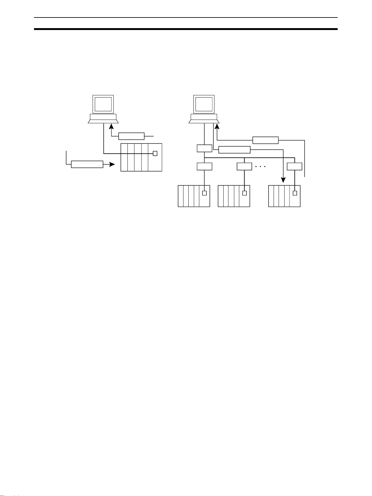
1-1 Overview of Communications Commands
Communications Commands Addressed to CS/CJ/CP/NSJ-series Units
A CS/CJ/CP-series CPU Unit or NSJ Controller can receive the following
communications commands.
C-mode commands via Host Link
Communications commands
FINS commands
C-mode Commands C-mode commands are specialized Host Link communications commands.
They are issued by a host computer and sent to a CPU Unit. The devices that
can be connected for serial communications are the CPU Unit, a Serial Communications Unit, and a Serial Communications Board.
FINS Commands FINS commands are message service communications commands. They do
not depend on a particular transmission path. They can be used for communications on various networks (Controller Link, Ethernet, etc.) and for serial
communications (Host Link). They can be issued from a CPU Unit, Special I/O
Unit, or host computer, and they can also be sent to any of these. The specific
commands that can be sent depend on the destination.
This manual explains commands sent to CS/CJ/CP-series CPU Units and
NSJ Controllers, when the commands are issued from a CPU Unit or a host
computer connected by Host Link.
Via CMND(490)/SEND(090)/RECV(098)
Via Host Link
Note When the source of the commands is a CPU Unit, the FINS commands are
sent by means of CMND(490)/SEND(090)/RECV(098). When the source is a
host computer, the FINS commands are issued using Host Link protocol.
1-2 C-mode Commands
The following table lists the C-mode (Host Link) commands. For details, refer
to SECTION 4 C-mode Commands.
Type Header
I/O memory
reading
code
RR CIO AREA READ Reads the specified number of words beginning with the
RL LR AREA READ Reads the specified number of words beginning with the
RH HR AREA READ Reads the specified number of words beginning with the
RC TIMER/COUNTER PV READ Reads the specified number of words of the timer/counter
RG TIMER/COUNTER STATUS
READ
RD DM AREA READ Reads the specified number of words beginning with the
RJ AR AREA READ Reads the specified number of words beginning with the
RE EM AREA READ Reads the specified number of words beginning with the
Name Function
designated CIO word.
designated LR word.
designated HR word.
PV beginning with the designated word.
Reads the specified number of words of the timer/counter
status beginning with the designated word.
designated DM word.
designated AR word.
designated EM word.
2
Page 25

C-mode Commands Section 1-2
Type Header
I/O memory
writing
Timer/counter SV
reading
Timer/counter SV
changing
CPU Unit status MS STATUS READ Reads the CPU Unit’s operating conditions (operating
Forced
set/reset
PLC model code
reading
Testing TS TEST Returns, just as it is, a single block that was sent from the
Program area
accessing
code
WR CIO AREA WRITE Writes the specified data in word units beginning with the
WL LR AREA WRITE Writes the specified data in word units beginning with the
WH HR AREA WRITE Writes the specified data in word units beginning with the
WC TIMER/COUNTER PV WRITE Writes the specified timer/counter PV data in word units
WD DM AREA WRITE Writes the specified data in word units beginning with the
WJ AR AREA WRITE Writes the specified data in word units beginning with the
WE EM AREA WRITE Writes the specified data in word units beginning with the
R# TIMER/COUNTER SV READ 1Reads in four digits BCD the constant SV that is written as
R$ TIMER/COUNTER SV READ 2Finds the specified timer/counter instruction, beginning
R% TIMER/COUNTER SV READ 3Finds the specified timer/counter instruction, beginning
W# TIMER/COUNTER SV
CHANGE 1
W$ TIMER/COUNTER SV
CHANGE 2
W% TIMER/COUNTER SV
CHANGE 3
SC STATUS CHANGE Changes the CPU Unit’s operating mode.
MF ERROR READ Reads the CPU Unit’s error information (i.e., all fatal or
KS FORCED SET Forcibly sets one designated bit.
KR FORCED RESET Forcibly resets one designated bit.
FK MULTIPLE FORCED
SET/RESET
KC FORCED SET/RESET CAN-
CEL
MM PLC MODEL READ Reads the model code of the CPU Unit.
RP PROGRAM READ Reads, in one batch, the contents of the CPU Unit’s user
WP PROGRAM WRITE Writes into the CPU Unit’s user program area the
Name Function
designated CIO word.
designated LR word.
designated HR word.
beginning with the designated word.
designated DM word.
designated AR word.
designated EM word.
an operand of the designated timer/counter instruction.
with the designated program address, and reads the constant SV in four digits or the word in which the SV is
stored.
with the designated program address, and reads the constant SV in four digits (BCD) or the word in which the SV
is stored.
Changes the SV of the specified timer/counter instruction
to a new constant SV.
Finds the specified timer/counter instruction, beginning
with the designated program address in the user program,
and changes the constant SV in four digits (BCD) or the
word in which the SV is stored to a new constant SV or
storage word.
Finds the specified timer/counter instruction, beginning
with the designated program address in the user program,
and changes the constant SV in four digits (BCD) or the
word in which the SV is stored to a new constant SV or
storage word.
mode, forced set/reset status, and fatal errors).
non-fatal errors currently in effect).
Forcibly sets/resets/cancels multiple designated bits.
Cancels all forced set/reset status.
host computer.
program at the machine language (object) level.
machine language (object) sent from the host computer.
3
Page 26

FINS Commands Section 1-3
Type Header
I/O table creation MI I/O TABLE CREATE Creates an I/O table with the contents of the actual I/O
I/O memory area
registration and
reading
Host Link communications
processing
code
QQMR REGISTER I/O MEMORY Registers the I/O memory words or bits that are to be
QQIR READ I/O MEMORY Reads the registered I/O memory words/bits all at once.
XZ ABORT (command only) Aborts the operation being performed by a Host Link com-
** INITIALIZE (command only) Initializes the transfer control procedures for all Host Link
IC Undefined command
(response only)
Name Function
configuration.
read.
mand, and then returns to the initial status.
Units.
This is the response when the command header code
cannot be decoded.
1-3 FINS Commands
The following table lists the FINS commands. For details, refer to SECTION 5
FINS Commands.
Type Command
I/O memory area
access
Parameter area
access
Program area
access
Operating mode
changes
Machine configuration reading
Status reading 06 01 CPU UNIT STATUS READ Reads the status of the CPU Unit.
Time data access 07 01 CLOCK READ Reads the present year, month, date,
code
MR SR
01 01 MEMORY AREA READ Reads the contents of consecutive I/O mem-
01 02 MEMORY AREA WRITE (See
note.)
01 03 MEMORY AREA FILL (See note.) Writes the same data to the specified range
01 04 MULTIPLE MEMORY AREA READ Reads the contents of specified non-consec-
01 05 MEMORY AREA TRANSFER (See
note.)
02 01 PARAMETER AREA READ Reads the contents of consecutive parame-
02 02 PARAMETER AREA WRITE (See
note.)
02 03 PARAMETER AREA FILL (CLEAR)
(See note.)
03 06 PROGRAM AREA READ Reads the UM (User Memory) area.
03 07 PROGRAM AREA WRITE (See
note.)
03 08 PROGRAM AREA CLEAR (See
note.)
04 01 RUN (See note.) Changes the CPU Unit’s operating mode to
04 02 STOP (See note.) Changes the CPU Unit’s operating mode to
05 01 CPU UNIT DATA READ Reads CPU Unit data.
05 02 CONNECTION DATA READ Reads the model numbers of the device cor-
06 20 CYCLE TIME READ Reads the maximum, minimum, and average
07 02 CLOCK WRITE (See note.) Changes the present year, month, date,
Name Function
ory area words.
Writes the contents of consecutive I/O mem-
ory area words.
of I/O memory area words.
utive I/O memory area words.
Copies the contents of consecutive I/O mem-
ory area words to another I/O memory area.
ter area words.
Writes the contents of consecutive parame-
ter area words.
Clears the specified range of parameter area
words.
Writes to the UM (User Memory) area.
Clears a specified range of the UM (User
Memory) area.
RUN or MONITOR.
PROGRAM.
responding to addresses.
cycle time.
minute, second, and day of the week.
minute, second, or day of the week.
4
Page 27

FINS Commands Section 1-3
Type Command
Message display 09 20 MESSAGE READ/CLEAR Reads and clears messages, and reads
Access rights 0C 01 ACCESS RIGHT ACQUIRE (See
Error log 21 01 ERROR CLEAR (See note.) Clears errors or error messages.
FINS write access
log
File memory 22 01 FILE NAME READ Reads file device data.
Debugging 23 01 FORCED SET/RESET (See note.) Force-sets or force-resets bits, or releases
code
MR SR
note.)
0C 02 ACCESS RIGHT FORCED
ACQUIRE
0C 03 ACCESS RIGHT RELEASE Releases the access right that has been
21 02 ERROR LOG READ Reads the error log.
21 03 ERROR LOG CLEAR (See note.) Clears all error log records.
21 40 FINS WRITE ACCESS LOG READ The CPU Unit automatically keeps a log of
21 41 FINS WRITE ACCESS LOG
CLEAR (See note.)
22 02 SINGLE FILE READ Reads a specified length of file data from a
22 03 SINGLE FILE WRITE (See note.) Writes a specified length of file data from a
22 04 FILE MEMORY FORMAT (See
note.)
22 05 FILE DELETE (See note.) Deletes specified files stored in the file
22 07 FILE COPY (See note.) Copies files from one file device to another
22 08 FILE NAME CHANGE (See note.) Changes a file name.
22 0A MEMORY AREA–FILE TRANSFER
(See note.)
22 0B PARAMETER AREA–FILE TRANS-
FER (See note.)
22 0C PROGRAM AREA–FILE TRANS-
FER (See note.)
22 15 DIRECTORY CREATE/DELETE
(See note.)
22 20 MEMORY CASSETTE TRANS-
FER (CP1H/CP1L CPU Units only)
23 02 FORCED SET/RESET CANCEL
(See note.)
Name Function
FAL/FALS messages.
Acquires the access right as long as no other
device holds it.
Acquires the access right even if another
device already holds it.
acquire.
any access for FINS write commands. This
command reads this log.
Clears the FINS write access log.
specified position within a single file.
specified position within a single file.
Formats (initializes) the file device.
device.
file device in the same system.
Transfers or compares data between the I/O
memory area and the file device.
Transfers or compares data between the
parameter area and the file device.
Transfers or compares data between the UM
(User Memory) area and the file device.
Creates or deletes a directory.
Transfers and verifies data between a Memory Cassette and the CPU Unit.
force-set status.
Cancels all bits that have been force-set or
force-reset.
Note These commands will not be accepted and an end code of 2102 hex (cannot
write due to protection) will be returned if the Write Protection from FINS
Commands Sent to CPU Units via Networks option is selected in the PLC
Setup for a CS/CJ-series CPU Unit with unit version 2.0 or later, for a CPseries CPU Unit, or for an NSJ Controller.
5
Page 28

FINS Commands Section 1-3
6
Page 29

Overview of C-mode Commands
This section provides an overview of C-mode (Host Link) commands.
2-1 C-mode Commands. . . . . . . . . . . . . . . . . . . . . . . . . . . . . . . . . . . . . . . . . . . . . 8
2-2 Command/Response Formats . . . . . . . . . . . . . . . . . . . . . . . . . . . . . . . . . . . . . 9
2-3 Application Example. . . . . . . . . . . . . . . . . . . . . . . . . . . . . . . . . . . . . . . . . . . . 14
2-4 Precautions when Reusing Programs from Earlier Models . . . . . . . . . . . . . . 15
2-4-1 C-series Host Link Units with 1:N Host Link Format Selected . . . . 15
2-4-2 C-series Host Link Units with 1:1 Host Link Format Selected . . . . 20
2-4-3 C-mode Command Support . . . . . . . . . . . . . . . . . . . . . . . . . . . . . . . 22
SECTION 2
7
Page 30
C-mode Commands Section 2-1
2-1 C-mode Commands
C-mode (Host Link) commands form a command/response system for serial
communications (Host Link Mode) to perform various control operations
between a CPU Unit and a host computer directly connected to it. These
operations include reading from and writing to I/O memory, changing operating modes, executing forced set and forced reset operations, and so on.
C-mode command
Response
C-mode command
Response
Note 1. There are two Host Link formats: the 1:N Host Link (with N ≥ 1) and the 1:1
Host Link.
• The 1:1 Host Link is the earlier Host Link format supported by C-series
PLCs, such as the C200H, C1000H, and C2000H.
• The built-in peripheral and RS-232C ports of CS/CJ-series CPU Units,
built-in serial ports of N-type CP1E CPU Units, serial port C on NSJ
Controllers, and serial ports 1 and 2 on the Option Board for CP-series
CPU Units support only the 1:N Host Link format. When a Serial Communications Board or Unit (version 1.2 or later) is being used, a 1:1
Host Link program created for a C-series PLC (C200H/C1000H/
C2000H) can be reused by selecting the Host Link 1:1 format.
In this manual, the term “Host Link” generally indicates the 1:N Host Link.
2. Unlike FINS commands, C-mode commands can only be addressed to a
CPU Unit, and they cannot be used for message service outside of the local network. They cannot be used for functions such as file operations.
C-mode (Host Link) commands can be sent from a host computer connected
to a CS/CJ-series Host Link Unit. Up to 32 PLCs (Host Link Units) can be connected to a single host computer. For identification, each Host Link Unit is
assigned a unit number from 0 to 31.
The length of a single unit of a command or response exchange is called a
“frame.” A single frame contains a maximum of 131 characters of data. Characters are sent and received as ASCII.
Note For a CS/CJ-series PLC, a “Host Link Unit” can be the CPU Unit, a Serial
Communications Unit, or a Serial Communications Board.
A maximum of 30 words of data can be transferred for the first command
frame and a maximum of 31 words of data can be transferred for other command frames when reading or writing word data in I/O memory. When reading/writing more than 30 words of data, the data transfer will be processed in
multiple transmissions, with 30 words in the first and up to 31 words in each of
8
Page 31

Command/Response Formats Section 2-2
)
the following transmissions until the number of words set in the command has
been processed.
The frame formats for Host Link commands sent from a host computer and
responses returned by the PLC receiving the commands are explained in the
following section.
2-2 Command/Response Formats
Single-frame Commands If a command is not more than 131 characters long, communications can be
completed by sending a single command frame. This is called a “single-frame
command.”
Command Frame Format
Terminator
Header code
Unit number (BCD)
Te xt
FCS
• @: Must be attached at the beginning of the command.
• Unit number: Set in BCD from 0 to 31 for each Host Link Unit.
• Header code: Specified in two characters.
• Text: Set parameters corresponding to command code.
• FCS: Calculate 2-character FCS (frame check sequence) at host
computer. For details on calculating FCS, refer to FCS Cal-
culations later in this section.
• Terminator: Set “*” and CR (CHR$(13)) as two characters to indicate
the end of the command.
Single-frame Response If a response is not more than 131 characters long, the communications can
be completed by returning one response frame. This is called a “single-frame
response.”
Response Frame Format
Header code
Unit number (BCD
End code (hexadecimal)
Te xt
FCS
• @: Must be attached at the beginning of the response.
• Unit number: Set in BCD from 0 to 31 for each Host Link Unit.
• Header code: The command code that was received is returned.
• End code: The results (error status, etc.) of command execution is
returned.
• Text: Returned only if there is read data.
Terminator
9
Page 32

Command/Response Formats Section 2-2
• FCS: The 2-character FCS (frame check sequence) is returned.
• Terminator: Two characters indicating the end of the command, “*” and
CR (CHR$(13)), are returned.
Error Response Formant If a reception error or an error in executing the command occurs, a response
is returned with no text.
Terminator
FCS
End code (hexadecimal)
Header code
Unit number (BCD)
Partitioned Commands If a command is longer than 131 characters, the command’s text is partitioned
by sending a delimiter [CR code, CHR$(13)] instead of a terminator at the end
of each command frame until the last one. A terminator is sent at the end of
the last frame. The procedure is given below for three command frames.
Note When sending command frames for writing (WR, WL, WC, WD, etc.), be care-
ful not to partition into separate frames data that is to be written into the same
word.
1,2,3... 1. From the host computer, attach a delimiter (CR) at the end of command
frame 1 and send the frame.
2. When the PLC receives this delimiter (CR), it will return only a delimiter
(CR) to the host computer.
3. From the host computer, attach a delimiter (CR) at the end of command
frame 2 and send the frame.
4. When the PLC receives this delimiter (CR), it will return only a delimiter
(CR) to the host computer.
5. From the host computer, attach a terminator (*CR) at the end of command
frame 3 and send the frame.
6. When the PLC receives this terminator (*CR), it will return the response
format with a terminator (*CR) attached to the end.
10
Page 33

Command/Response Formats Section 2-2
p
The following diagram shows the command format when there are more than
131 characters.
Command frame 1 Command frame 2 Command frame 3
Host
Computer
Header code
@Unit number
PLC
Te xt
FCS
Delimiter
128 characters max. 128 characters max.
Delimiter
FCS
Te xt
Delimiter
Delimiter
FCS
Te xt
Terminator
Te xt
FCS
Terminator
Header code
@Unit number
End code
Res
onse frame
Note A “delimiter” is a CR code [CHR$(13)] sent as a single character to indicate
the middle of a command or response.
Partitioned Responses If a response is more than 131 characters long, the response from the PLC is
partitioned by returning a delimiter (CR code, CHR$(13)) instead of a terminator at the end of each frame until the last one. A terminator is returned at the
end of the last frame.
In the following example procedure, the response is partitioned into three
frames.
1,2,3... 1. When the PLC receives the command frame from the host computer, it re-
turns response frame 1 with a delimiter (CR) at the end to the host computer.
2. Only a delimiter (CR) is sent from the host computer to the PLC.
3. When the PLC receives this delimiter (CR), it returns response frame 2
with a delimiter (CR) at the end to the host computer.
4. Only a delimiter (CR) is sent from the host computer to the PLC.
5. When the PLC receives this delimiter (CR), it returns response frame 3
with a terminator (*CR) at the end to the host computer.
11
Page 34

Command/Response Formats Section 2-2
The following diagram shows the response format when there are more than
131 characters.
Command frame
Te xt
FCS
Header code
Host computer
@Unit number
131 characters max.
Terminator
Delimiter
Delimiter
PLC
Te xt
End code
Header code
@Unit number
Response frame 1
FCS
Delimiter
Te xt
FCS
Delimiter
Response frame 2
128 characters max. 128 characters max.
Te xt
FCS
Terminator
Response frame 3
Note 1. Frames in partitioned commands or responses must have not more than
128 characters including the delimiter/terminator.
2. Delimiters from the host computer are detected by the presence of a CR
code. The delimiter will be detected even if there is data in front of it.
12
Page 35

Command/Response Formats Section 2-2
FCS Calculations The PLC calculates the FCS (Frame Check Sequence) value for each com-
mand frame it receives, and it checks for errors by comparing that value with
the FCS value sent with the command frame. The host computer must calculate the FCS value when sending a command frame.
Also, when checking for errors in response frames, the host computer must
calculate the FCS value for each response frame it receives and compare that
value to the FCS value sent in the response frame.
Header code
Unit number
FCS calculation range
ASCII
Code
@ 40 0100 0000
EOR
1 31 0011 0001
EOR
0 30 0011 0000
EOR
R 52 0101 0010
1 31 0011 0001
0100 0010
Calculation result
(See note.)
4 Hex
Te xt
•
•
•
Note The FCS is an 8-bit value converted into two ASCII characters. The 8-bit
value is the result of an exclusive OR sequentially performed between each
character in a transmission, from the first character in the frame to the last
character of the text in that frame. Non-ASCII data, however, may sometimes
be sent in the text data. If the data length is 7 bits, the leftmost bit of each
character is masked before the FCS is calculated.
2 Hex
Terminator
FCS
The value is converted to hexadecimal
and handled as ASCII.
13
Page 36

Application Example Section 2-3
2-3 Application Example
Sending a Host Link Command from a Host Computer
In this example program, a Host Link command is sent from a host computer
and a response is received.
10 ’CS1 SAMPLE PROGRAM FOR EXCEPTION
20 CLOSE
30 CLS
40 OPEN “COM:E73”AS#1
50 *KEYIIN
60 INPUT ”DATA
70 IF S$=””THEN GOTO 190
80 PRINT ”SEND DATA=”;S$
90 ST$=S$
100 INPUT ”SEND OK? Y or N?=”,BS
110 IF B$=”Y” THEN GOTO 130 ELSE GOTO *KEYIN
120 S$=ST$
130 PRINT #T,S$ Sends command to PLC.
140 INPUT #1,R$ Receives command from PLC.
150 PRINT ”RECV DATA=”;R$
160 IF MID$(R$,4,2)=”EX”THEN GOTO 210 Identifies command.
170 IF RIGHT$(R$,1)<>”*”THEN S$=””:GOTO 130
180 GOTO *KEYIN
190 CLOSE 1
200 END
210 PRINT ”EXCEPTION!!DATA”
220 GOTO 140
–”,S
Explanation
1,2,3... 1. The host computer’s transmission/reception program is started up, and the
Host Link command is input.
2. The Host Link command that was input is sent to the PLC, and the data
that is received is displayed on the screen.
Note The example program up to this point does not include an error processing
routine in case reception is not normal (e.g., if there is no FCS). Include error
processing routines when creating an actual program.
400 *FCSCHCK
410 L=LEN(RESPONSE$) Transmission/reception data
420 Q=0:FCSCK$=””
430 A$=RIGHT$(RESPONSE$,1)
440 PRINT RESPONSE$,A$,L
450 IF A$=”*”THEN LENGS=LEN(RESPONSE$)
ELSE LENGS=LEN(RESPONSE$)
460 FCSP$=MID$(RESPONSE$,LENGS+1,2) FCS data that is received
470 FOR I=1 TO LENGS Number of characters in FCS calculation
480 Q=ASC(MID$(RESPONSE$1,1))XOR Q
490 NEXT 1
500 FCSD$=HEX$(Q)
510 IF LEN(FCSD$) =1 THEN FCSD$=”0”+FCSD$ FCS calculation result
520 IF FCSD$<>FCSP$ THEN FCSCK$=”ERR”
530 PRINT ”FCSD$=”;FCSD$,”FCSP$=”;FCSP$,”FCSCK$=”;FCSCK$
Normal FCS reception: “ ” (space); abnormal FCS reception: “ERR”
540 RETURN
–2
–3
14
Page 37

Precautions when Reusing Programs from Earlier Models Section 2-4
2-4 Precautions when Reusing Programs from Earlier Models
Observe the following precautions when reusing host computer programs created for communications with C-series Host Link Units.
2-4-1 C-series Host Link Units with 1:N Host Link Format Selected
Using the CPU Unit's Built-in Peripheral Port or RS-232C Port
Number of Data Words per Frame
When I/O memory data is read with the following commands, the number of
data words in each response frame is different for a C-series Host Link Unit
compared to the built-in peripheral and RS-232C ports on CS/CJ-series CPU
Units, serial port C on NSJ Controllers, built-in serial ports of N-type CP1E
CPU Units, and serial ports 1 and 2 on the Option Board for CP-series CPU
Units.
With a C-series Host Link Unit, the first frame can contain up to 29 words of
data (text) and the following frames can contain up to 30 words of data (text).
With the built-in peripheral and RS-232C ports on CS/CJ-series CPU Units,
serial port C on NSJ Controllers, built-in serial ports of N-type CP1E CPU
Units, and serial ports 1 and 2 on the Option Board for CP-series CPU Units,
the first frame can contain up to 30 words of data (text) and the following
frames can contain up to 31 words of data (text).
Header code Name
RR CIO AREA READ
RL LR AREA READ
RH HR AREA READ
RC TIMER/COUNTER PV READ
RG TIMER/COUNTER STATUS READ
Note: The number of data words per response frame is different
for the RG command than for the other C-mode commands.
For details, see the table Words per Frame for C-mode RG
Command below.
RD DM AREA READ
RJ AR AREA READ
Because the Units do not have the same number of words per response
frame, the data may not be read properly if a host computer program originally
used with a C-series Host Link Unit is reused with a CS-series CPU Unit, CJseries CPU Unit, CP-series CPU Unit, or NSJ Controller. In this case, be sure
to edit the host computer program so that it is compatible with the frame format.
Note Serial Communications Boards and Units with version numbers 1.2 and later
are equipped with a Host Link model compatibility selection function that
changes the Host Link function's specifications to match the frame format of
other Units in the Host Link. It is not necessary to edit an existing program if
the Host Link model compatibility selection function is set to match the Host
Link format used in the program. For details, see Using a Serial Communica-
tions Board or Unit with Version Number 1.2 or Later below.
15
Page 38

Precautions when Reusing Programs from Earlier Models Section 2-4
Words per Frame for C-mode Commands (Except RG Command)
Units C Series CS/CJ Series CVM1 and CV Series Data words per frame
C-series
Host Link
Units
Other
Boards and
Units
C200H-LK101/LK201/
LK202 Host Link Units
C500-LK103/LK203
Host Link Units
3G2A5-LK101/LK201
Host Link Units
3G2A6-LK101/LK201/
LK202 Host Link Units
SRM1 built-in ports
CPM1 built-in ports
CPM1A built-in ports
CQM1-CPU
ports
C200HS-CPU
in ports
C200HX/HG/HE-
CPU
C200HW-COM@@
Communications Board
ports
@@ built-in
@@ built-
@@ built-in ports
st
frame
1
--- --- 29 words 30 words
CS2H-CPU
built-in ports
CS1G/H-CPU
built-in ports
CS1G/H-CPU
built-in ports
CS1D-CPU
in ports
CJ1G/H-CPU
built-in ports
CJ1G-CPU@@ built-in
ports
CJ1M-CPU@@ built-in
ports
CS1W-SCB21-V1/
41-V1 (unit version:
Pre-Ver. 1.2) Serial
Communications Board
ports
CS1W-SCU21-V1 (unit
version: Pre-Ver. 1.2)
Serial Communications Unit ports
CJ1W-SCU21/41 (unit
version: Pre-Ver. 1.2)
Serial Communications Unit ports
@@(-EIP)
@@H
@@-EV1
@@H built-
@@H
CVM1-CPU
ports
CV-CPU
ports
CV500-LK201 Host
Link Unit
@@ built-in
@@ built-in
30 words 31 words
Other frames
16
Page 39

Precautions when Reusing Programs from Earlier Models Section 2-4
Words per Frame for C-mode RG Command
Units C Series CS/CJ Series CVM1 and CV Series Data words per frame
C-series
Host Link
Units
Other
Boards and
Units
C200H-LK101/LK201/
LK202 Host Link Units
C500-LK103/LK203
Host Link Units
3G2A5-LK101/LK201
Host Link Units
3G2A6-LK101/LK201/
LK202 Host Link Units
SRM1 built-in ports
CPM1 built-in ports
CPM1A built-in ports
CQM1-CPU
ports
CQM1H-CPU
in ports
CQM1H-SCB
in ports
C200HX/HG/HE-
CPU
C200HW-COM
Communications Board
ports
@@ built-in
@@ built-
@@ built-
@@ built-in ports
@@
st
frame
1
--- --- 89 words 89 words
--- --- 89 words 60 words
CS2H-CPU@@(-EIP)
built-in ports
CS1G/H-CPU
built-in ports
CS1G/H-CPU
built-in ports
CS1D-CPU
in ports
CJ1G/H-CPU
built-in ports
CJ1G-CPU@@ built-in
ports
CJ1M-CPU
ports
CS1W-SCB21-V1/41V1 (unit version: PreVer. 1.2) Serial Communications Board
ports
CS1W-SCU21-V1 (unit
version: Pre-Ver. 1.2)
Serial Communications Unit ports
CJ1W-SCU21/41 (unit
version: Pre-Ver. 1.2)
Serial Communications Unit ports
@@H
@@-EV1
@@H built-
@@H
@@ built-in
CVM1-CPU
ports
CV-CPU
ports
CV500-LK201 Host
Link Unit
@@ built-in
@@ built-in
121 words 125 words
Other frames
Note There are several exceptions to the number of words per frame values shown
in the table above:
The following responses are returned when reading 246 words of Timer/
Counter Completion Flags through CS/CJ-series CPU Unit built-in ports, CS/
CJ-series Serial Communications Units/Boards, C200HX/HG/HE CPU Unit
built-in ports, or C200HS CPU Unit built-in ports.
1st frame 2nd frame 3rd frame
121 words 124 words 1 word
The second-to-last frame contains 124 data words and the last frame contains
1 word. This also applies when the number of words is 246 + a multiple of 125
(i.e., 371 words, 496 words, 621 words, etc.).
The following responses are returned when reading 121 words of Timer/
Counter Completion Flags through CS/CJ-series Unit built-in ports.
st
1
frame 2nd frame
120 words 1 word
17
Page 40

Precautions when Reusing Programs from Earlier Models Section 2-4
The following responses are returned when reading 121 words or 246 words
through CVM1 and CV-series CPU Unit built-in ports or CVM1/CV-series Host
Link Units.
Number of Words = 121
1st frame 2nd frame
121 words 0 words (terminator only)
Number of Words = 246
st
frame 2nd frame 3rd frame
1
121 words 125 words 0 words (terminator only)
The second-to-last frame contains 125 data words and the last frame contains
the terminator only. This also applies when the number of words is 246 + a
multiple of 125 (i.e., 371 words, 496 words, 621 words, etc.). For responses
containing the terminator only, “00*CR” (00 = FCS, CR = carriage return) is
returned.
Response Format for MS Command
With the MS command (STATUS READ), the response data format when
using CVM1 or CV-series built-in ports or Host Link Units, is different from the
response data format when using other Units.
When a CVM1/CV CPU Unit's built-in Host Link port or CVM1/CV Series Host
Link Unit is used and an FAL or FALS instruction has not been executed,
spaces (ASCII code 20 hex) will be included in the response data for the FAL/
FALS message. With all other Host Link Units, the FAL/FALS message data is
included in the response only when an FAL or FALS instruction has been executed.
Using a Pre-Ver. 1.2 Serial Communications Board or Unit
The response formats are the same as described above under the heading
Using the CPU Unit's Built-in Peripheral Port or RS-232C Port.
Using a Serial Communications Board or Unit with Version Number 1.2 or Later
The Serial Communications Board or Unit’s Host Link function can be made
completely compatible with the existing PLC’s Host Link function by setting
the appropriate Host Link mode (1:N or 1:1 Host Link) and the Host Link
model compatibility mode.
Host Link Model Compatibility Selection Function
Serial Communications Boards and Units with version Ver. 1.2 and later are
equipped with a Host Link model compatibility selection function. This function
switches the Board or Unit’s Host Link specifications to match the specifications of an existing Host Link program that is being reused. The following
specifications can be switched by the Host Link model compatibility function.
• Words per Response Frame
Sets the number of data words per response frame when receiving the fol-
lowing I/O memory read commands (RR, RL, RH, RC, RD, RJ, or RG).
• Sets the response frame format for the STATUS READ command (MS),
which varies when an FAL or FALS instruction has not been executed.
18
Page 41

Precautions when Reusing Programs from Earlier Models Section 2-4
Host Link Model Compatibility Modes
Host link
model
compatibility
mode
A mode
(CS, CJ, and
C)
B mode
(CVM1/CV)
C mode
(C200H)
D mode
(C500/C120)
Host link model
(Model used as basis for host
computer’s program)
C Series
SRM1 built-in ports
CPM1 built-in ports
CPM1A built-in ports
CQM1-CPU
C200HS-CPU
C200HX/HG/HE-CPU
C200HW-COM@@ Communications
Board ports
CS/CJ Series
CS2H-CPU
CS1G/H-CPU
CS1G/H-CPU
CS1D-CPU@@H built-in ports
CJ1G/H-CPU
CJ1G-CPU@@ built-in ports
CJ1M-CPU@@ built-in ports
CS1W-SCB21-V1/41-V1 (unit version:
Pre-Ver. 1.2) Serial Communications
Board ports
CS1W-SCU21-V1 (unit version: Pre-Ver.
1.2) Serial Communications Unit ports
CJ1W-SCU21/41 (unit version: Pre-Ver.
1.2) Serial Communications Unit ports
CVM1-CPU
CV-CPU@@ built-in ports
CV500-LK201 Host Link Unit
C200H-LK101/LK201/LK202 Host Link
Units
C500-LK103/LK203 Host Link Units
3G2A5-LK101/LK201 Host Link Units
3G2A6-LK101/LK201/LK202 Host Link
Units
@@ built-in ports
@@ built-in ports
@@ built-in ports
@@(-EIP) built-in ports
@@H built-in ports
@@-EV1 built-in ports
@@H built-in ports
@@ built-in ports
RR, RL, RH, RC, RD,
and RJ commands
Data words per response frame Response
st
1
frame 2nd frame 1st frame 2nd frame
30 words 31 words 121
29 words 30 words 89 words 89 words Variable
RG command MS
125
words
89 words 60 words
words
command
(see note)
data format
Var iable
length
Fixed length
length
Note When the MS command reads the CPU Unit’s status data and an FAL or
FALS instruction has not been executed, spaces (ASCII code 20 hex) are
included as the FAL/FALS message in the response frame for some models
(fixed length response in the table above). In the other models, no data is
included as the FAL/FALS message in the response frame (variable length
response frame) if an FAL or FALS instruction has not been executed.
19
Page 42

Precautions when Reusing Programs from Earlier Models Section 2-4
Relationship to the 1:N Host Link/1:1 Host Link Setting
The following table shows the allowed Host Link format (1:N Host Link/1:1 Host
Link) settings for each Host Link model compatibility setting.
Host link model
compatibility mode
A mode (CS, CJ, and C)
and B mode (CVM1/CV)
C mode (C500/C120)
and D mode (C200H)
Settings for an Example Unit Replacement
Use the following settings when the existing host computer was created for a
system with C500-LK103/LK203 Host Link Units and/or 3G2A5-LK101/LK201
Host Link Units, a new Serial Communications Board or Unit (Ver. 1.2 or later)
is being used, and the Host Link format is 1:1 Host Link.
• Host link 1:N format/1:1 format setting: 1 (1:1 Host Link format)
• Host link model compatibility mode setting: 3 (C mode (C500/C120))
Only the 1:N Host Link format can be used.
Either the 1:N Host Link format or 1:1 Host Link format
can be selected.
Host link format
2-4-2 C-series Host Link Units with 1:1 Host Link Format Selected
Using the CPU Unit's Built-in Peripheral Port or RS-232C Port
Only the 1:N Host Link format is supported by the CPU Unit’s built-in peripheral port and RS-232C port. A host computer program cannot be used if it was
developed for a 1:1 Host Link.
Using a Pre-Ver. 1.2 Serial Communications Board or Unit
Only the 1:N Host Link format is supported by Pre-Ver. 1.2 Serial Communications Boards and Units. A host computer program cannot be used if it was
developed for a 1:1 Host Link.
Using a Serial Communications Board or Unit with Version Number 1.2 or Later
The Serial Communications Boards and Units with version number 1.2 or later
can be set to operate in 1:1 Host Link mode, so a host computer program
developed for a 1:1 Host Link with C-series PLCs (C200H, C1000H, and
C2000H) can be reused in a CS/CJ Series Host Link. (The 1:1 Host Link for-
20
Page 43

Precautions when Reusing Programs from Earlier Models Section 2-4
mat can be selected with the 1:N format/1:1 format setting in the allocated DM
Area settings.)
Host link
format
1:N format With this Host Link
1:1 format With this Host Link
Usage Applicable PLC models Remarks
format, the connection configuration
(host: PLC) can be
either 1:1 or 1:N.
Earlier versions of
these Boards/Units
supported only the
1:N format.
format, the connection configuration
(host: PLC) can be
1:1 only.
C Series
SRM1 built-in ports
CPM1 built-in ports
CPM1A built-in ports
CQM1-CPU
C200HS-CPU
C200HX/HG/HE-CPU@@ built-in ports
C200HW-COM
Board ports
CS/CJ Series
CJ2H-CPU
CS1G/H-CPU
CS1G/H-CPU
CS1D-CPU
CJ1G/H-CPU
CJ1G-CPU@@ built-in ports
CJ1M-CPU@@ built-in ports
Earlier versions (unit version: Pre-Ver. 1.2)
CS1W-SCB21-V1/41-V1 Serial Communications Board ports
CS1W-SCU21-V1 Serial Communications
Unit ports
CJ1W-SCU21/41 Serial Communications
Unit ports
CVM1/CV Series
CVM1-CPU
CV-CPU
CV500-LK201 Host Link Unit
C Series
C500-LK103/LK203 Host Link Units
3G2A5-LK101/LK201 Host Link Units
3G2A6-LK101/LK201/LK202 Host Link
Units
C Series
C200H-LK101/LK201/LK202 Host Link
Units
C Series
C500-LK103/LK203 Host Link Units
3G2A5-LK101/LK201 Host Link Units
3G2A6-LK101/LK201/LK202 Host Link
Units
C Series
C200H-LK101/LK201/LK202 Host Link
Units
@@ built-in ports
@@ built-in ports
@@ Communications
@@(-EIP) built-in ports
@@H built-in ports
@@-EV1 built-in ports
@@H built-in ports
@@H built-in ports
@@ built-in ports
@@ built-in ports
Only the 1:N Host Link format is supported by the built-in ports on CPU
Units of CS/CJ, C200HS, C200HX/HG/
HE, CPM
as the ports on Host Link Units and
Serial Communications Boards.
Earlier versions of the Serial Communications Boards/Units support only the
1:N Host Link format.
Only the 1:N Host Link format is supported by the built-in ports on CPU
Units of CVM1/CV Series PLCs as well
as the ports on Host Link Units and
Serial Communications Units/Boards.
Either the 1:N Host Link or 1:1 Host
Link format can be selected with these
C-series Host Link Units.
Either the 1:N Host Link or 1:1 Host
Link format can be selected with these
C-series Host Link Units.
@, and CQM1@ PLCs as well
Note The following diagrams show the differences in the command and response
frames with the 1:N Host Link format and 1:1 Host Link format.
21
Page 44

Precautions when Reusing Programs from Earlier Models Section 2-4
r
r
1:N Format
• Command
0 R D
0
@
××
*
CR
Unit number
in host link
Header
code
• Response
0 R D 0 0
0
Unit number
in host link
Header
code
1:1 Format
As shown in the following diagrams, the 1:1 format is equivalent to the 1:N format without the @ character, Host Link unit number, and FCS byte.
• Command format
R D CR
Header
code
• Response format
R D 0 0 CR
Header
code
End
code
2-4-3 C-mode Command Support
code
*
Terminator
*
Terminato
FCS
Terminato
××
FCS
*
CR@
TerminatorEnd
Use the following table as reference when reusing programs for host computers developed for earlier Host Link models.
• If a command is not supported for the new model of PLC, consider using
another C-mode or FINS command.
• Even if the command is supported, differences may exist in the data sizes
that can be processed or in the meaning of the values if the models or
Series vary.
• Refer to the applicable operation manuals for details.
22
Page 45

Precautions when Reusing Programs from Earlier Models Section 2-4
Note Refer to information on the previous page for commands with “Caution” in the
Frame data size column.
Frame
Header
data
code
size
Cau-
RR CIO AREA
tion
Cau-
RL LR AREA
tion
Cau-
RH HR AREA
tion
Cau-
RC TIMER/
tion
Cau-
RG TIMER/
tion
Cau-
RD DM AREA
tion
Cau-
RJ AR AREA
tion
OK RE EM AREA
NA RX FILE MEM-
NA RF FILE MEM-
NA CR DM AREA
NA GM DM SIZE
Cau-
WR CIO AREA
tion
Cau-
WL LR AREA
tion
Cau-
WH HR AREA
tion
Cau-
WC TIMER/
tion
Cau-
WD DM AREA
tion
Cau-
WJ AR AREA
tion
OK WE EM AREA
NA R# TIMER/
NA R$ TIMER/
NA R% TIMER/
NA W# TIMER/
Name CS/CJ
READ
READ
READ
COUNTER PV
READ
COUNTER
STATUS READ
READ
READ
READ
ORY DELUXE
READ
ORY READ
READ (FIXED)
CHANGE
WRITE
WRITE
WRITE
COUNTER PV
WRITE
WRITE
WRITE
WRITE
COUNTER SV
READ 1
COUNTER SV
READ 2
COUNTER SV
READ 3
COUNTER SV
CHANGE 1
Series
C200HE
CPU Unit or Serial
Communications Board or Unit
--- --- --- --- --- --- --- --- None
C200HS C120 C200H
/HG/HX
CPU Unit or
Communications Board
CPU Unit
C120 (3G2A6) Host Link Unit
C200HS
C200HE/
HG/HX
C Series CVM1 and
C500 C1000H
C200H Host Link Unit
C2000H
C500F C1000HF CQM1 SRM1
C500 (3G2A5) Host Link Unit
CPM1
CPM1A
CPU Unit
CPU Unit
or V1
CV Series
CPU Unit
CPU Unit
V2 ---
Ye s Ye s Ye s Ye s Ye s Ye s Ye s Ye s Ye s Ye s Ye s Ye s Ye s Yes
Ye s Ye s Ye s Ye s Ye s Ye s Ye s Ye s Ye s Ye s Ye s N o Ye s N o
Ye s Ye s Ye s Ye s Ye s Ye s Ye s Ye s Ye s Ye s Ye s N o Ye s N o
Ye s Ye s Ye s Ye s Ye s Ye s Ye s Ye s Ye s Ye s Ye s Ye s Ye s Yes
Ye s Ye s Ye s Ye s Ye s Ye s Ye s Ye s Ye s Ye s Ye s Ye s Ye s Yes
Ye s Ye s Ye s Ye s Ye s Ye s Ye s Ye s Ye s Ye s Ye s Ye s Ye s Yes
Ye s Ye s Ye s N o Ye s N o Ye s N o Ye s Ye s Ye s Ye s Y e s Y e s
Yes Yes No No No No No No No No No No No No
No No No No No No Yes No Yes No No No No No
No No No No No No Yes No Yes No No No No No
No No No No No No Yes No Yes No No No Yes No
No No No No No No No Yes Yes No No No No No
Ye s Ye s Ye s Ye s Ye s Ye s Ye s Ye s Ye s Ye s Ye s Ye s Ye s Yes
Ye s Ye s Ye s Ye s Ye s Ye s Ye s Ye s Ye s Ye s Ye s N o Ye s N o
Ye s Ye s Ye s Ye s Ye s Ye s Ye s Ye s Ye s Ye s Ye s N o Ye s N o
Ye s Ye s Ye s Ye s Ye s Ye s Ye s Ye s Ye s Ye s Ye s Ye s Ye s Yes
Ye s Ye s Ye s Ye s Ye s Ye s Ye s Ye s Ye s Ye s Ye s Ye s Ye s Yes
Ye s Ye s Ye s N o N o No Ye s N o Ye s Ye s Ye s Y e s Ye s Yes
Yes Yes No No No No No No No No No No No No
Ye s Ye s Ye s Ye s Ye s Ye s Ye s Ye s Ye s Ye s Ye s N o Ye s N o
Ye s Ye s Ye s Ye s Ye s Ye s Ye s Ye s Ye s Ye s Ye s N o Ye s N o
Ye s Ye s Ye s Ye s Ye s Ye s Ye s Ye s Ye s Ye s N o N o Ye s No
s Ye s Ye s Ye s Ye s Ye s Ye s Ye s Ye s Ye s Ye s N o Ye s No
Ye
CV500 Host Link Unit
23
Page 46

Precautions when Reusing Programs from Earlier Models Section 2-4
Frame
Header
data
code
size
NA W$ TIMER/
NA W% TIMER/
N A M S S TATU S R EA D Ye s Ye s Ye s Ye s Ye s Ye s Ye s Ye s Ye s Ye s Yes Ye s Ye s Ye s
NA SC STATUS
N A M F ER RO R R EA D Ye s Ye s Ye s Ye s Ye s Ye s Ye s Ye s Ye s Ye s Yes Ye s Ye s Ye s
NA KS FORCED SET Yes Yes Yes Yes Yes Yes Yes Yes Yes Yes Yes Yes Yes Yes
NA KR FORCED
NA FK MULTIPLE
NA FR MULTIPLE
NA KC FORCED SET/
NA MM PLC MODEL
N A T S T E S T Yes Ye s Ye s Ye s Ye s Ye s Ye s Ye s Ye s Ye s Ye s Ye s Y e s Y e s
NA RP PROGRAM
NA WP PROGRAM
NA MI I/O TABLE
NA QQMR/
QQIR
NA XZ ABORT (com-
NA ** INITIALIZE
NA IC Undefined
NA EX TXD
NA FA FINS MES-
NA OF FINS MES-
Name CS/CJ
COUNTER SV
CHANGE 2
COUNTER SV
CHANGE 3
CHANGE
RESET
FORCED SET/
RESET
FORCED SET/
RESET STATUS READ
RESET CANCEL
READ
READ
WRITE
CREATE
REGISTER/
READ I/O
MEMORY
mand only)
(command
only)
command
(response only)
RESPONSE
(response only)
SAGE
SAGE (slaveinitiated)
Series
C200HE
/HG/HX
CPU Unit or Serial
Communications Board or Unit
--- --- --- --- --- --- --- --- None
C200HS C120 C200H
CPU Unit or
Communications Board
CPU Unit
C120 (3G2A6) Host Link Unit
C200HS
C200HE/
HG/HX
C Series CVM1 and
C200H Host Link Unit
C500 C1000H
C2000H
C500F C1000HF CQM1 SRM1
C500 (3G2A5) Host Link Unit
CPM1A
CPU Unit
CPM1
CPU Unit
or V1
CV Series
CPU Unit
V2 ---
CPU Unit
CV500 Host Link Unit
Ye s Ye s Ye s Ye s Ye s Ye s Ye s Ye s Ye s Ye s Ye s N o Ye s N o
Ye s Ye s Ye s Ye s Ye s Ye s Ye s Ye s Ye s Ye s N o N o Ye s No
Ye s Ye s Ye s Ye s Ye s Ye s Ye s Ye s Ye s Ye s Ye s Ye s Ye s Yes
Ye s Ye s Ye s Ye s Ye s Ye s Ye s Ye s Ye s Ye s Ye s Ye s Ye s Yes
Yes Yes Yes No Yes No No No No Yes Yes No Yes No
No Yes Yes No Yes No No No No No No No No No
Ye s Ye s Ye s Ye s Ye s Ye s Ye s Ye s Ye s Ye s Ye s Ye s Ye s Yes
Ye s Ye s Ye s Ye s Ye s Ye s Ye s Ye s Ye s Ye s Ye s Ye s Ye s Yes
Ye s Ye s Ye s Ye s Ye s Ye s Ye s Ye s Ye s Ye s Ye s Ye s Ye s Yes
Ye s Ye s Ye s Ye s Ye s Ye s Ye s Ye s Ye s Ye s Ye s Ye s Ye s Yes
Ye s Ye s Ye s Ye s Ye s Ye s Ye s Ye s Ye s N o N o Ye s Ye s Ye s
Ye s Ye s Ye s Ye s Ye s Ye s Ye s Ye s Ye s Ye s Ye s Ye s Ye s Yes
Ye s Ye s Ye s Ye s Ye s Ye s Ye s Ye s Ye s Ye s Ye s Ye s Ye s Yes
Ye s Ye s Ye s Ye s Ye s Ye s Ye s Ye s Ye s Ye s Ye s Ye s Ye s Yes
Ye s Ye s Ye s Ye s Ye s Ye s Ye s Ye s Ye s Ye s Ye s Ye s Ye s Yes
NoYesNoNoNo NoNoNoNo NoNoNoNoNo
YesNo NoNoNo NoNoNoNo NoNoYesYesYes
YesNo NoNoNo NoNoNoNo NoNoYesYesYes
24
Note When using CVM1 or CV-series built-in ports or Host Link Units, the response
data format for the MS command (STATUS READ) is different from the format
for other Units. For details, refer to 4-3-23 STATUS READ – – MS.
Page 47

Precautions when Reusing Programs from Earlier Models Section 2-4
Manuals for Host Link Operations
PLC Product Model (suffixes omitted) Manual type Catalog No.
CS/CJ Series Communications
commands (Cmode and FINS)
Serial Communications Unit/Board CS1W-SCB21-V1/41-V1
C200HX/HG/HE CPU Unit
C200HS CPU Unit
C Series Host Link Units C200H-LK101/201/202
CQM1 CPU Unit
CPM1 CPU Unit
CPM1A CPU Unit
SRM1 CPU Unit
CVM1 and
CV Series
CPU Unit
Host Link Unit CV500-LK201
CPU Unit
Serial Communications Unit/
Board
CJ2H-CPU
CS1G/H-CPU
CS1G/H-CPU@@-EV1
@@(-EIP)
@@H
CS1D-CPU@@H
CJ1M-CPU@@
CJ1G/H-CPU@@H
CJ1G-CPU
CS1W-SCB21-V1/41-V1
CS1W-SCU21-V1
CJ1W-SCU21/41
CS1W-SCU21-V1
CJ1W-SCU21/41
C200HX/HG/HE-CPU
C200HX/HG/HE-CPU
C200HS-CPU
C500-LK201/203
3G2A5-LK101/103
3G2A6-LK101/201/202
CQM1-CPU
CPM1-
CPM1A-
SRM1-C
CVM1/CV-CPU
@@
@@
@@-Z
@@
@@
@@@@@
@@@@@
@@
@@
Reference
Manual
Operation
Manual
Operation
Manual
Operation
Manual
Operation
Manual
System
Manual
Programming
Manual
Operation
Manual
Operation
Manual
Operation
Manual
Operation
Manual
W342-E1
W336-E1
W303-E1
W322-E1
W235-E1
W143-E1
W228-E1
W262-E1
W317-E1
W318-E1
W205-E1
25
Page 48

Precautions when Reusing Programs from Earlier Models Section 2-4
26
Page 49

Overview of FINS Commands
This section provides an overview of FINS commands.
3-1 FINS Commands. . . . . . . . . . . . . . . . . . . . . . . . . . . . . . . . . . . . . . . . . . . . . . . 28
3-2 Using FINS Commands . . . . . . . . . . . . . . . . . . . . . . . . . . . . . . . . . . . . . . . . . 30
3-2-1 Issuing and using any command (CMND (490) instruction) . . . . . . 31
3-2-2 Using with respect to a host computer connected by Host Link . . . 31
3-3 FINS Command and Response Frames . . . . . . . . . . . . . . . . . . . . . . . . . . . . . 32
3-3-1 FINS Command Frame Configuration . . . . . . . . . . . . . . . . . . . . . . . 32
3-3-2 FINS Response Frame Configuration. . . . . . . . . . . . . . . . . . . . . . . . 32
3-3-3 Individual Items in Command/Response Frames . . . . . . . . . . . . . . . 33
3-4 Settings for Sending FINS Commands . . . . . . . . . . . . . . . . . . . . . . . . . . . . . . 34
3-4-1 FINS Command and Response Formats. . . . . . . . . . . . . . . . . . . . . . 35
3-4-2 Addresses in FINS Commands. . . . . . . . . . . . . . . . . . . . . . . . . . . . . 36
3-4-3 Other FINS Command Settings . . . . . . . . . . . . . . . . . . . . . . . . . . . . 41
3-4-4 CMND(490) Setting Example . . . . . . . . . . . . . . . . . . . . . . . . . . . . . 42
3-5 FINS Commands with Host Link Protocol . . . . . . . . . . . . . . . . . . . . . . . . . . . 43
3-5-1 Connection Configurations. . . . . . . . . . . . . . . . . . . . . . . . . . . . . . . . 43
3-5-2 Overview of Command and Response Frames. . . . . . . . . . . . . . . . . 44
3-5-3 Sending Commands from the Computer to the CPU Unit . . . . . . . . 45
3-5-4 Sending FINS Commands to the Host Computer from the CPU Unit 49
3-5-5 Sending Commands from the CPU Unit . . . . . . . . . . . . . . . . . . . . . 50
3-5-6 Command Format Received by the Host Computer. . . . . . . . . . . . . 55
3-5-7 Response Format Returned by the Host Computer . . . . . . . . . . . . . 57
3-5-8 Flags for Network Communications. . . . . . . . . . . . . . . . . . . . . . . . . 58
3-5-9 Timing of Commands to Host Computers . . . . . . . . . . . . . . . . . . . . 59
3-5-10 Programming Example. . . . . . . . . . . . . . . . . . . . . . . . . . . . . . . . . . . 62
3-6 Serial Gateway Overview . . . . . . . . . . . . . . . . . . . . . . . . . . . . . . . . . . . . . . . . 66
3-6-1 Overview. . . . . . . . . . . . . . . . . . . . . . . . . . . . . . . . . . . . . . . . . . . . . . 66
3-6-2 Types of Protocol Conversion . . . . . . . . . . . . . . . . . . . . . . . . . . . . . 67
3-6-3 Converting FINS to CompoWay/F. . . . . . . . . . . . . . . . . . . . . . . . . . 67
3-6-4 Converting FINS to Modbus-RTU . . . . . . . . . . . . . . . . . . . . . . . . . . 70
3-6-5 Converting from FINS to Modbus-ASCII . . . . . . . . . . . . . . . . . . . . 73
3-6-6 Converting from FINS to Host Link FINS . . . . . . . . . . . . . . . . . . . . 74
3-6-7 Treating Serial Communications Paths as Networks . . . . . . . . . . . . 78
3-6-8 Using a PLC as the Target . . . . . . . . . . . . . . . . . . . . . . . . . . . . . . . . 79
3-6-9 Using a non-PLC Component as the Target . . . . . . . . . . . . . . . . . . . 81
3-6-10 Explanation. . . . . . . . . . . . . . . . . . . . . . . . . . . . . . . . . . . . . . . . . . . . 84
3-7 Communications Frames. . . . . . . . . . . . . . . . . . . . . . . . . . . . . . . . . . . . . . . . . 86
3-7-1 CompoWay/F . . . . . . . . . . . . . . . . . . . . . . . . . . . . . . . . . . . . . . . . . . 86
3-7-2 Modbus-RTU . . . . . . . . . . . . . . . . . . . . . . . . . . . . . . . . . . . . . . . . . . 87
3-7-3 Modbus-ASCII . . . . . . . . . . . . . . . . . . . . . . . . . . . . . . . . . . . . . . . . . 88
3-7-4 Host Link FINS. . . . . . . . . . . . . . . . . . . . . . . . . . . . . . . . . . . . . . . . . 89
3-7-5 Sending Commands Using the CMND(490) Instruction . . . . . . . . . 90
SECTION 3
27
Page 50

FINS Commands Section 3-1
3-1 FINS Commands
FINS commands form a command system for message services across different OMRON networks. They can be used for various control operations, such
as sending and receiving data, changing operating modes, executing forced
set and forced reset operations, performing file operations, and so on. FINS
commands make it possible to freely communicate with Units in various networks and on CPU Racks by simply specifying the network, node, and unit.
FINS commands have the following features:
1,2,3... 1. They are defined in the application level and do not depend on lower levels
(i.e., the physical and data link levels). This allows them to be used across
a variety of networks and CPU buses. Specifically, they can be used with
Ethernet, Controller Link, and Host Link networks, and between CPU Units
and CPU Bus Units.
Note FINS commands can be sent with UDP/IP headers when using
Ethernet and with Host Link command headers when using Host
Link.
2. FINS commands can be used to access various kinds of devices besides
CPU Units. Devices such as CPU Units, CPU Bus Units, personal computers (boards), and Inner Boards can be identified and specified by their unit
addresses.
CPU Bus Unit
Inner Board
CPU Unit
Personal computer board
3. FINS commands support network relay operations, so they can pass
through a network hierarchy to access devices on up to three network levels (including the local network).
Network 2
Network 1
Network 3
Note With CS/CJ-series CPU Units with unit version 2.0 or later, CP-series CPU
Units, or NSJ Controllers, devices can be accessed on up to 8 network levels.
When the destination of a FINS command is a CPU Unit, the command can
be sent through as many as 8 network levels. When the destination of a FINS
command is a node other than a CPU Unit, the command can be sent through
a maximum of 3 network levels.
28
Page 51

FINS Commands Section 3-1
r
• The following table shows the maximum number of network levels that
can be crossed by various PLC models.
PLC model Network levels
CS/CJ-series CPU Unit with
unit version 3.0
CP-series CPU Unit *1,
NSJ Controller
CS/CJ-series CPU Unit with
unit version 2.0
Pre-Ver. 20. CS/CJ-series
CPU Units and CVM1/CVseries CPU Units
*1: Not possible with a CP1E CPU unit.
• When crossing up to 3 network levels, the CS/CJ-series CPU Units with
unit version 2.0 and later, CP-series CPU Units, and NSJ Controllers can
be combined with other models. When crossing 4 to 8 network levels,
configure the system with only unit version 2.0 and later CS/CJ-series
CPU Units, CP-series CPU Units, and NSJ Controllers. (Other models
cannot be combined in the network with CS/CJ-series CPU Units with unit
version 2.0 and later, CP-series CPU Units, and NSJ Controllers.) If earlier models are used, a routing error (end codes 0501 to 0504) will occur
and the response may not be returned to the node that sent the command.
For details, refer to 1-4-2 Communications through a Maximum of 8 Network
Levels in the CS Series PLC Operation Manual or the CJ Series PLC Operation Manual.
(Gateway counter setting)
It is possible to select a maximum of either 8 lev-
els or 3 levels. (Set with CX-Programmer Ver.
5.0.)
Setting fixed at 8 levels max.
Setting fixed at 3 levels max.
Types of FINS Commands There are basically two kinds of FINS commands: Those addressed to CPU
Units and those addressed to CPU Bus Units. Among FINS commands for
CPU Units, there are commands addressed to the various models of CPU
Unit, such as the CS/CJ/CP-series CPU Units, NSJ Controllers, CV-series
CPU Units, C200HX/HG/HE CPU Units, and so on. The basic code system is
the same, but the detailed specifications vary according to the CPU Unit.
Among FINS commands for CPU Bus Units, there are commands addressed
to Controller Link Units, to DeviceNet Master Units, to Ethernet Units, and so
on.
FINS Commands
Addressed to CS/CJ/CPseries CPU Units and NSJ
Controllers
PLC on another network CS/CJ-series PLC
CPU
Unit
Computer
CS/CJ/CP-series CPU Units and NSJ Controllers can receive FINS commands from a PLC (CS/CJ, CVM1/CV, or C200HX/HG/HE(-Z) CPU Unit) or
computer on another network or from a host computer connected directly to
the local network.
Host compute
FINS command
CPU Unit
FINS command
29
Page 52

Using FINS Commands Section 3-2
1,2,3... 1. A FINS command sent from a PLC or computer on another network is
transmitted to the CPU Unit from the Backplane of the CPU Rack, via a
Communications Unit (Controller Link Unit, Ethernet Unit, etc.)
2. FINS commands sent from a host computer to a CPU Unit are sent with a
Host Link header code and a terminator (as in the Host Link communications mode).
Host computer
Communications
Unit
CS1-series
CPU Unit
Serial communications (Host Link mode)
FINS command
FINS command
Communications Unit
CPU Unit
PLC on network
Network (Controller Link, Ethernet, etc.)
Computer on network
Communications Board
The FINS commands available for CS/CJ/CP-series CPU Units and NSJ Controllers fall into the following broad categories. (Refer to the relative operation
manuals for FINS commands addressed to other Units and Boards.)
• I/O memory area reading and writing
• Parameter area reading and writing
• Program area reading and writing
• Operating mode changes
• Machine configuration reading
• CPU Unit status reading
• Time data access
• Message reading and clearing
• Access rights acquisition and release
• Error log reading and clearing
• File operations
• Forced set/reset
Note When the Ethernet option board (CP1W-CF41) is used, a FINS command
issued from a PLC or computer on the network can be received via the
Ethernet option board, but cannot be issued via the Ethernet option board.
3-2 Using FINS Commands
FINS commands addressed to CPU units are issued to CS/CJ/CP-series
CPU units and NSJ Controllers by executing the instruction for the FINS command (SEND/RECV/CMND instruction) from a program of another PLC (CPU
unit) on the network.
Executing a FINS command addressed to a CPU unit can be used for the following:
• Issuing and using any command (CMND instruction)
• Using with respect to a host computer connected by Host Link
30
Page 53

Using FINS Commands Section 3-2
3-2-1 Issuing and using any command (CMND (490) instruction)
The procedure for execution by CMND instruction is described below.
1,2,3... 1. Store the command format of the FINS command (i.e., the command data)
in an I/O memory area, such as the DM area.
2. In the same way, store the control data (number of bytes of transmission
data, destination address, etc.) in an I/O memory area, such as the DM area.
3. Designate S (first command word), D (first response word), and C (first
control word) for the CMND(490) operands, and execute the instruction.
4. When the FINS response is returned from the destination node (a CS/CJ/
CP-series CPU Unit or an NSJ Controller), the data will be stored according to the response format beginning at the first response word.
1 byte
CMND(490) execution
1 byte
Word
@CMND
S
D
C
Communications Unit
(Controller Link Unit,
etc.)
Command
Response
1 byte 1 byte
Word
CS/CJ-series CPU Unit
Command format data
Response format data
Command frame
FINS header
Automatically attached.
Response frame
FINS header
Automatically attached.
2 bytes
Command
code
2 bytes 1,998 bytes max.2 bytes
Command
code
End
code
Control data
2,000 bytes max.
Tex t
Tex t
Designates where to send, etc.
CS/CJ-series
CPU Unit
Note FINS commands and responses are handled as binary data, and data is sent
and received in binary format. (Host Link communications, however, are basically in ASCII.)
3-2-2 Using with respect to a host computer connected by Host Link
With Host Link communications, a FINS command frame with a Host Link
header and a terminator is sent from a host computer to a CS/CJ/CP-series
CPU Unit or NSJ Controller. The basic frame formats are shown below.
Note Host Link communications handle ASCII data, so data is sent and received in
ASCII. For that reason, FINS command and response frames must also be
sent and received in ASCII when they are handled using Host Link communications.
31
Page 54

FINS Command and Response Frames Section 3-3
Command Frame
Host Link header FINS command frame (See note.)
Host Link
FCS
Note A FINS command frame also consists of the destination node address, the
source node address, and other FINS command format data.
The CS/CJ/CP-series CPU Unit or NSJ Controller that receives the command
will return the following response frame to the host computer.
Response Frame
Host Link header
FINS response frame (See note.)
Host Link
FCS
Note A FINS response frame also consists of the contents set (e.g., requested) at
the time of transmission and the FINS command response format data.
It is also possible to send a FINS command frame with a Host Link header
and terminator from a CS/CJ/CP-series (not possible from a CP1E CPU unit)
CPU Unit or NSJ Controller to a host computer connected by Host Link System (unsolicited communications initiated by a slave).
3-3 FINS Command and Response Frames
If the data from the command code onwards is set in the words specified with
S when a FINS command is sent by means of CMND(490), a FINS header will
be generated automatically and attached, and the FINS command frame will
be sent. When the FINS response frame is received, the FINS header will be
automatically removed and the response data from the command code
onwards will be stored as specified in the words specified with operand D.
When a FINS command is sent by Host Link communications, the header is
attached before the FINS frame, and the FCS and terminator are attached
after it.
Host Link terminator
Host Link terminator
3-3-1 FINS Command Frame Configuration
Command
code
FINS header (automatically attached for CMND(490))
*With Host Link communications, the header, FCS, and terminator are attached before and after the frame.
*Set in word specified for CMND(490) operand S onwards.
3-3-2 FINS Response Frame Configuration
End
code
32
Command
code
FINS header (deleted automatically for CMND(490))
*With Host Link communications, the header, FCS, and terminator are added before and after the frame.
*Set in word specified for CMND(490) operand D onwards.
Te xt
Te xt
Page 55

FINS Command and Response Frames Section 3-3
3-3-3 Individual Items in Command/Response Frames
ICF
The ICF (Information Control Field) is configured as shown in the following
diagram.
Bit
Always 0. (See note.)
Response (0: Required; 1: Not required)
Data classification (0: Command; 1: Response)
Bridges (0: Not used; 1: Used)
Always 1.
Note Set bits 01 to 05 to 0 when sending a FINS command. Do not access these
bits when receiving a FINS response.
RSV
RSV (Reserved) is always 00 hex. These bits are used by the system. Do not
access them in the response.
GCT
When communicating across up to 8 network layers with CPU Unit with unit
version 2.0 or later, set the GCT (Gateway Count: Number of Bridges Passed
Through) to 07 hex when sending a FINS command. Otherwise, set the GCT
to 02 hex (see note) when sending. When receiving a FINS response, GCT is
decremented one for each bridge (network) that is passed through and the
resulting value is received. This value is for system use; do not access it.
Note
For a CS/CJ-series CPU Unit with unit version 2.0 or later, CP-series CPU Unit,
or NSJ Controller, CX-Programmer version 4.0 or higher can be used to set routing tables that start the GCT at 07 hex. For a CS/CJ-series CPU Unit with unit
version 3.0 or later, CX-Programmer (CX-Net) Ver. 5.0 or higher can be used to
set routing tables that start the GCT at either 07 Hex or 02 Hex. For details, refer
to 1-4-2 Communications through a Maximum of 8 Network Levels in the CS
Series PLC Operation Manual or the CJ Series PLC Operation Manual.
DNA
Destination network address. Specify within the following ranges (hex).
00: Local network
01 to 7F: Remote network address (decimal: 1 to 127)
DA1
Destination node address. Specify within the following ranges (hex).
00: Internal communications in PLC
01 to 20: Node address in Controller Link Network (1 to 32 decimal)
01 to FE: Ethernet (1 to 254 decimal,
for Ethernet Units with model numbers ending in ETN21)
FF: Broadcast transmission
DA2
Destination unit address. Specify within the following ranges (hex).
00: CPU Unit
FE: Controller Link Unit or Ethernet Unit connected to network
10 to 1F: CPU Bus Unit
E1: Inner Board
SNA
Source network address. Specify within the following ranges (hex).
00: Local network
01 to 7F: Remote network (1 to 127 decimal)
33
Page 56

Settings for Sending FINS Commands Section 3-4
SA1
Source node address. Specify within the following ranges (hex).
00: Internal communications in PLC
01 to 20: Node address in Controller Link Network (1 to 32 decimal)
01 to FE: Ethernet (1 to 254 decimal,
for Ethernet Units with model numbers ending in ETN21)
SA2
Source unit address. Specify within the following ranges (hex).
00: CPU Unit
10 to 1F: CPU Bus Unit
SID
Service ID. Used to identify the process generating the transmission. Set the
SID to any number between 00 and FF
Note 1. The unit address for a CPU Bus Unit is 10 (hexadecimal) plus the unit num-
ber set on the front panel of the CPU Bus Unit.
2. With a CS/CJ-series CPU Unit with unit version 2.0, CP-series CPU Unit,
or NSJ Controller, the GCT (Gateway Count: Number of Bridges Passed
Through) in FINS command/response frames is decremented from to 07
hex (variable). The GCT was previously decremented from 02 hex. For CS/
CJ-series CPU Unit with unit version 3.0 or later, the GCT (Gateway Count:
Number of Bridges Passed Through) in FINS command/response frames
is decremented from to 02 hex by default. If the user specified CX-Net for
this CPU Unit version, the GCT will be decremented from 07 hex. With a
CS/CJ-series CPU Unit with unit version 3.0 or later, NSJ Controller, or CPseries CPU Unit, the GCT will be decremented from 02 hex by default and
from 07 hex if the user selects CX-Net.
3. The GCT (Gateway Count: Number of Bridges Passed Through) in the
FINS header in FINS command/response frames should not be checked
in the user applications, e.g., in the host computer. The GCT is for system
use only and verification may fail if attempted from a user application. This
is particularly important for CS/CJ-series CPU Unit with unit version 2.0 or
later, CP-series CPU Unit, or NSJ Controller.
3-4 Settings for Sending FINS Commands
Command format
Settings for sending
FINS commands
Address
Other
Note 1. Set these as operands when executing CMND(490).
2. Do not set the gateway count when using CMND(490).
34
Network address
Node address
Unit address
Response required/not required
Number of retries (See note 1.)
Communications port No. (See note 1.)
Response monitor time (See note 1.)
Gateway count (See note 2.)
Page 57

Settings for Sending FINS Commands Section 3-4
3-4-1 FINS Command and Response Formats
Command Format As shown below, the command format basically consists of the command
code (four digits hexadecimal) and parameters (text).
Command code (See note.)
4 digits hexadecimal
(2 bytes)
Text (Various kinds of data)
The length depends on the command code.
Note The command code is a 2-byte code that expresses the content of the com-
mand. A FINS command must begin with a 2-byte command code. If there is
also text, it is added after the command code.
Example: Command for Reading I/O Memory
01 01 Hex
Memory area
code
Command code
Beginning read
address
Te xt
Number of
read elements
The following data would read 10 words starting from D00010.
01 01 Hex
Command
code
Memory area
code
First read
address
Parameters
000A Hex00 0A 00 Hex82 Hex
Number of
read elements
Response Format As shown below, the response format basically consists of the command code
(four digits hexadecimal), end code, and parameters (text).
Command code
4 digits hexadecimal
(2 bytes)
Note The end code is a 2-byte code that shows the command execution result.
End code (See note.)
Text (Various kinds of data)
The length depends on the command code.
(The first byte shows the general category, and the second byte shows the
detailed results.)
Example: Response from Reading I/O Memory
01 01 Hex
Command code
End code
End code
Read data
Te xt
Actual response data would be as follows:
01 01 Hex
00 00 Hex
Command
code
Response
code
Text: 10 words (20 bytes)
of read data.
35
Page 58

Settings for Sending FINS Commands Section 3-4
3-4-2 Addresses in FINS Commands
FINS commands are transmitted across networks and to various devices (via
network nodes). Designate the addresses as follows:
• Designate the device from which the command is to be sent, the network
that the device is on, and the node through which the command is to transit.
• Designate the device to which the command is to be sent, the network the
device is on, and the node through which command is to transit.
Addresses must be provided for the network, node, and device (unit) to identify them. FINS commands include these addresses (the transmission source
and destination addresses) in the command/response frames.
Addresses for FINS Commands
Address Values Designation method
Network address 1 to 127 (01 to 7F Hex)
Node address 1 to 254 (01 to FE Hex) (See note.)
Local node address: 00 Hex
Note The node addresses differ for each
network.
Internal Communications in PLC: 00 Hex
For Controller Link: 01 to 3E Hex (1 to 62)
For Ethernet Units with model numbers
ending in ETN21
: 01 to FE Hex (1 to 254)
For Ethernet Units with other model
numbers
Unit address •CPU Unit: 00 Hex
•CPU Bus Unit: Unit No.+ 10 Hex
•Special I/O Unit: Unit No.+ 20 Hex
•Inner Board: E1 Hex
•Computer: 01 Hex
•Unit connected to network: FE Hex
: 01 to 7E Hex (1 to 126)
CMND(490) operand
designation
Ye s Ye s
Ye s Ye s
Ye s Ye s
Designation in frame
when frame is created
Devices on the Same Network
Example
Node address 1
Address Source address (See note 1.) Destination address
FINS command
symbol
Network address SNA 00 Hex DNA 00 Hex
Node address SA1 01 Hex DA1 03 Hex
Unit address SA2 00 Hex DA2 00 Hex
Example value FINS command
Node address 2
PLCPLC
symbol
Node address 3
PLC
For CPU Unit
(00 Hex)
(See note 2.)
Example value
Note 1. The transmission source address will be automatically incorporated into
the frame if the FINS command is sent with CMND(490). If sending the
36
Page 59

Settings for Sending FINS Commands Section 3-4
FINS command by Host Link communications, then put the source address in the message.
2. Set the transmission destination address in the control code (C) operand
if sending the FINS command with CMND(490). If sending the FINS command by Host Link communications, then put the destination address in
the message.
Devices on Different Networks
Example
Node address 1
PLC
Network address 1
Address level Source address (See note 1.) Destination address
FINS command
symbol
Network address SNA 01 Hex DNA 02 Hex
Node address SA1 01 Hex DA1 05 Hex
Unit address SA2 00 Hex DA2 00 Hex
PLC
Example value FINS command
PLC
Network address 2
symbol
Node address 5
PLC
For CPU Unit
(00 Hex)
(See note 2.)
Example value
Note 1. The transmission source address will be automatically incorporated into
the frame if the FINS command is sent with CMND(490). If sending the
FINS command by Host Link communications, then put the source address in the message.
2. Set the transmission destination address in the control code (C) operand
if sending the FINS command with CMND(490). If sending the FINS command by Host Link communications, then put the destination address in
the message.
Unit Addresses Set the unit address for the following purposes:
• To identify the Unit when there is more than one device connected at the
same node on a network.
• To identify the type of device (CPU Unit, CPU Bus Unit, etc.) at the destination.
Note The meanings of FINS commands will vary depending on the Unit at the des-
tination even when the commands have the same command code. This is why
the Unit at the destination must be identified by the unit address.
Unit addresses are as follows:
• CPU Unit: 00 Hex
• CPU Bus Unit: Unit number + 10 hex
• Special I/O Unit:
Unit number + 20 hex
• Inner Board: E1 Hex (CS Series only)
• Computer: 01 Hex
• Communications Unit with the specified node address connected to network with the specified network address (Controller Link or Ethernet):
FE Hex
37
Page 60
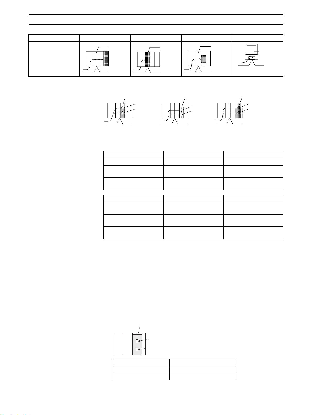
Settings for Sending FINS Commands Section 3-4
Unit address 00 Hex Unit No. + 10 Hex E1 Hex 01 Hex
Contents
Node
address
Node
address
Note It is also possible to set the serial port (No. 1 to 4) for the destination device.
Node
address
Node
address
Unit Addresses for
Computers Connected to
Serial Ports
Serial Communications Unit
Serial port 1
Serial port 2
Serial Communications
Board
Serial port 1
Serial port 2
CPU Unit
The unit addresses for host computers connected to a CS/CJ/CP/NSJ serial
port (e.g., on a CPU Unit, Option Board, Serial Communications Unit, or
Serial Communications Board) are shown in the following table.
Unit/Board Peripheral port RS-232C port
CS/CJ-series CPU Unit FD Hex (253 decimal) FC Hex (252 decimal)
NSJ Controller --- FC Hex (Serial port C on
Controller Section)
Built-in serial ports of
N-type CP1E CPU Units
Unit/Board Serial port 1 Serial port 2
CS/CJ -series Serial
Communications Board
CS/CJ-series Serial
Communications Unit
CP-series Option Board
(See Note.)
Note
A FINS command to a host computer cannot be issued from a CP1E CPU unit.
--- ---(See note.)
E4 Hex E5 Hex
80 Hex + 04 Hex x unit
number
FD Hex FC Hex
81 Hex + 04 Hex x unit
number
Serial port 1
Serial port 2
Unit Addresses for Serial
Ports on Serial
Communications Boards
and Units
38
For the SEND, RECV, and CMND instructions, the CPU Unit will add the proper unit
address based on the unit address of the Unit/Board and the specified serial port. It
is not necessary to consider these addresses in the ladder-diagram program.
The network address and serial port's unit address must be allocated and the routing table's local
network table must be created for Several settings are required when making network settings
(FINS command system settings) for serial communications through a serial port on a CS Series
Serial Communications Board or CS/CJ Series Serial Communications Unit. The network
address and the serial port's unit address (permanent) must be allocated and the routing table's
local network table must be created. The following diagrams show serial port's unit address.
• Example 1: Serial Communications Board
Serial Communications Board
Serial port 1
Serial port 2
Serial port on Board Serial port's unit address
Serial port 1 E4 hex (228 decimal)
Serial port 2 E5 hex (229 decimal)
Page 61
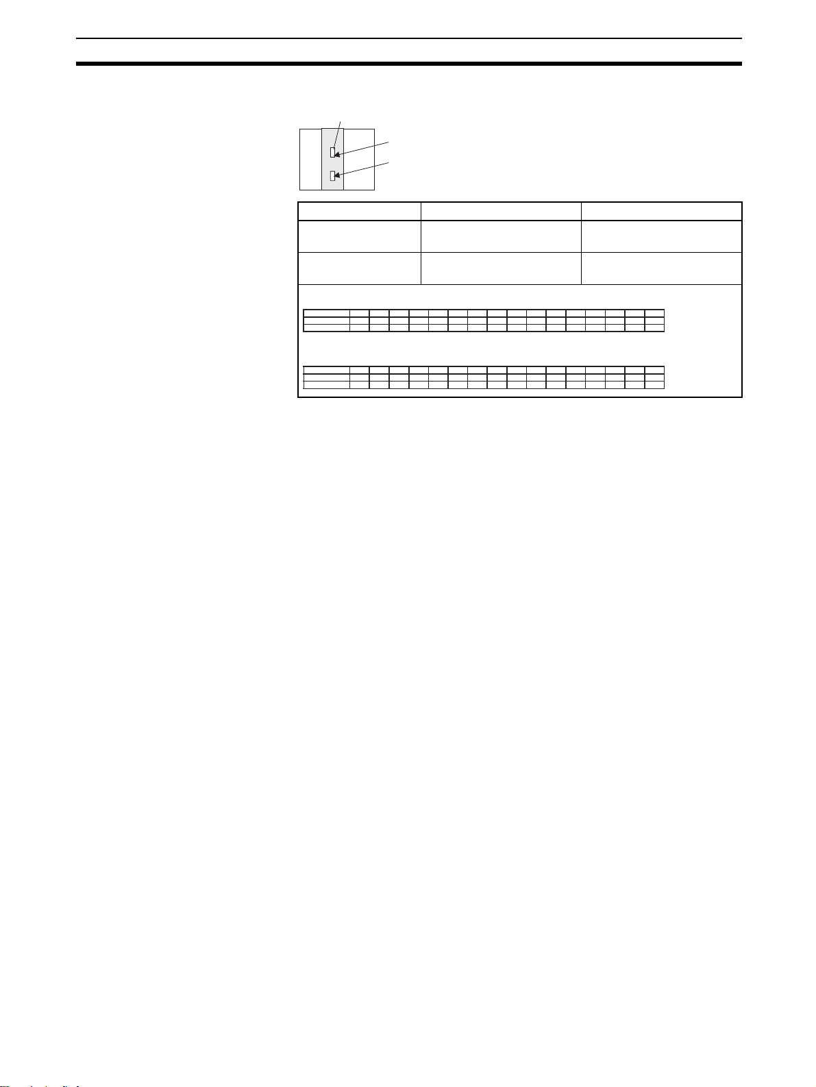
Settings for Sending FINS Commands Section 3-4
2
• Example 2: Serial Communications Unit
Serial Communications Unit
Serial port 1
Serial port
Serial port on Unit Serial port's unit address Example: Unit number 1
Serial port 1 80 hex + 04 hex × unit num-
ber
Serial port 2 81 hex + 04 hex × unit num-
ber
Unit addresses for serial port 1:
Unit number
Hexadecimal
Decimal
0 1 2 3 4 5 6 7 8 9 A B C D E F
88
80 84 8C 90 94 98 9C A0 A4 A8 AC B0 B4 B8 BC
128 132 136 140 144 148 152 156 164 168 172 176 180 184 188
160
Unit addresses for serial port 2:
Unit number
Hexadecimal
Decimal
0 1 2 3 4 5 6 7 8 9 A B C D E F
81
85
8D 91
95 99
129 133 137 141 145 149 153
89
9D A1 A5 A9 AD B1 B5 B9 BD
157 161
165 173 177 181 185 189
Summary of Addresses The three addresses used in FINS commands can be summarized as follows
(refer to the following diagram):
Network Address
An address that identifies the entire network. All nodes on the same network
have the same network address.
Node Address
An address that identifies an individual node on a network, such as a PLC or
host computer.
80 hex + 04 hex × 1 = 84
hex (132 decimal)
81 hex + 04 hex × 1 = 85
hex (132 decimal)
169
39
Page 62
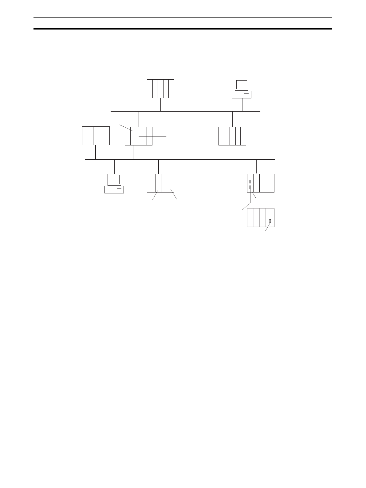
Settings for Sending FINS Commands Section 3-4
Unit Address
For a PLC, an address that identifies the specific Unit that is participating in
the communication in the PLC. For a host computer, an address that identifies
the specific application that is participating in the communication in the computer.
PLC
Node address: 5
Computer
Node address: 1
PLC
Node address: 8
Computer
Node address: 11
Controller Link Unit
Unit address: 12 Hex
Communications Unit
(Controller Link Unit)
Unit address: 12 Hex
Node address: 8
PLC
Node address: 7
Ethernet Unit
Unit address:
15 Hex
Controller Link Network
Network address 2
PLC
Node address: 3
CPU Unit
Unit address:
0 Hex
Serial
communications
(Host Link)
Unit address of
serial port 2 of the
Serial Communications Unit: 81
Hex + 04 Hex ×
unit number
Ethernet network
Network address 1
PLC
Node address: 2
PLC
Node address: 5
Serial Communications Unit
PLC
Node address: (Host
Link unit number (0
to 31) + 1
RS-232C port on
CPU Unit
40
Page 63

Settings for Sending FINS Commands Section 3-4
3-4-3 Other FINS Command Settings
Aside from the addresses, the following data must be set.
Setting Content Values Designation method
Number of retries Number of times to retry sending
the command.
Port No. Logical communications port. CS/
CJ/CP-series CPU Units have 8
communications ports, so 8 communications commands can be
executed simultaneously. To execute 9 or more commands, simultaneously, it is necessary to set up
exclusive control.
Serial port No. Specifies the number of the serial
Response monitor time
Response
required/ not
required
(ICF bit 0)
Gateway count Designates the number of net-
port of the Unit with Host Link
capabilities.
Monitors the time it takes to return
a response. If a response is not
returned within the designated
time, a response timeout is generated.
Designates whether or not a
response is required.
works that can be accessed.
CMND(490)
operand
designation
0 to F Hex (0 to 15 times) Yes No
0 to 7 Hex Yes No
0: Unit/Board
1: Serial port 1 for Serial
Communications Board/
Unit or Peripheral port for
CPU Unit
2: Serial port 2 for Serial
Communications Board/
Unit or RS-232C port for
CPU Unit
0001 to FFFF Hex (0.1 to
6,553.5 seconds)
0 or 1 (bit) Yes Yes
00 to 07 Hex No Yes
Ye s N o
Ye s N o
Designation in
frame when
frame is created
Note 1. Unit address are fixed for Units and Boards, as well as for serial ports. For
the SEND(090), RECV(098), and CMND(490) instructions, the CPU Unit
will add the proper unit address based on the unit address of the Unit/
Board and the specified serial port. It is not necessary to consider these
addresses in the ladder-diagram program.
Serial Port 1:
80 Hex + 04 Hex x unit number for Serial Communications Units, E4 Hex for
Serial Communications Boards, and FC Hex (CPU Unit’s RS-232C or serial port 2 on CP1H Option Board)
Serial Port 2:
81 Hex + 04 Hex x unit number for Serial Communications Units, E5 Hex for
Serial Communications Boards, and FD Hex (CPU Units peripheral port or
serial port 1 on CP1H Option Board)
2. The gateway count is decremented one for each bridge (network) that is
passed through.
41
Page 64

Settings for Sending FINS Commands Section 3-4
3-4-4 CMND(490) Setting Example
The designated number of bytes of FINS command data from the first command word designated by operand S is sent to the designated unit address
via the node address on the network address designated by operand C, and
the response is stored for the number of bytes of data received starting from
D.
S: First command word
D: First response word
C: First control word
In this example, a command (MEMORY AREA READ: 0101 Hex) for reading
D00010 to D00019 of the PLC at node 02 is sent using CMND(490).
D00010: Memory area code (82 Hex), address 000A00
Number of elements read: 10 = 0A Hex
S: First command word
0101
Command code
0082
Memory area code
0A 00
Beginning read address
0A00
Number of elements read
D: First response word
0101
Control code
Beginning read address
C: First control word
0800
Number of command data bytes
1800
Number of response data bytes
0000
Destination network address
Serial port No.
0002
Destination unit address
Destination node address
0300
Number of retries
Communications port number
Response required/not required
0000
42
0000
End code
Read data
Read data
Response monitor time
Page 65

FINS Commands with Host Link Protocol Section 3-5
t
3-5 FINS Commands with Host Link Protocol
FINS commands can be sent and received using the Host Link protocol
between interconnected host computers and PLCs.
3-5-1 Connection Configurations
One of the following two methods can be used to send and receive FINS commands using the Host Link protocol.
Sending from a Computer to a CPU Unit
Note The host computer can be connected to the peripheral port or RS-232C port
on the CPU Unit or to a serial ports on a Serial Communications Unit/Board.
The Host Link protocol must be used regardless of the point of connection.
CPU Unit Directly Connected to Host Computer
CPU Uni
Host Link
FINS command
CPU Units on a Network
Host Link
FINS command
Network (Controller Link, Ethernet, etc.)
Sending from a CPU Unit to a Computer (Slave Initiation)
Note 1. Slave initiation is not possible from a CP1E CPU.
2. The host computer can be connected to the peripheral port or RS-232C
port on the CPU Unit or to a serial ports on a Serial Communications Unit/
Board. The Host Link protocol must be used regardless of the point of connection.
CPU Unit Directly Connected to Host Computer
CPU Unit CPU Unit
SEND(090)
RECV(098)
CMND(490)
CPU Unit
Host Link
FINS command
43
Page 66

FINS Commands with Host Link Protocol Section 3-5
CPU Unit Directly Connected to Host Computer on a Network
SEND(090)
RECV(098)
CMND(490)
CPU Unit
Host Link
FINS command
Network (Controller Link, Ethernet, etc.)
Note 1. Host Link communications handle ASCII data, so data is sent and received
in ASCII. Hexadecimal values in FINS command and response frames
must, therefore, also be sent and received in ASCII when they are handled
using Host Link communications.
2. When a FINS command sent from a host computer or the CPU Unit (with
the CMND instruction) is received by a Serial Communications Board or
Unit with version number Ver. 1.2 or later, that PLC acts as the Host Link
Master and it can send the FINS command to a Slave PLC through the
Host Link system.
3. When the Ethernet option board (CP1W-CF41) is used, a FINS command
cannot be issued to Host Link via the Ethernet option board.
CPU Unit
Serial Communications Unit
Ver. 1.2 or later
Serial
Gateway
PLC (Host link Master)
FINS
FINS
Host link
header
CMND
Host link
terminator
Sends FINS command
FINS
Host link
header
PLC (Host link Slave)
Host link
terminator
3-5-2 Overview of Command and Response Frames
When FINS commands and responses are sent or received using Host Link
communications, the frame must be preceded by a Host Link header and followed by a Host Link FCS and terminator as shown below.
Command Frame Use the following format to send FINS command frames.
Host Link header FINS command frame (See note.)
Host Link
FCS
Host Link terminator
44
Note A FINS command frame also consists of the response wait time, the destina-
tion node address, the source node address, and other FINS command format data.
Page 67

FINS Commands with Host Link Protocol Section 3-5
Response Frame The CS/CJ/CP-series CPU Unit or NSJ Controller that receives the command
will return the following response frame to the host computer.
Host Link header
FINS response frame (See note.)
Host Link
FCS
Host Link terminator
Note A FINS response frame also consists of the contents set at the time of trans-
mission and the FINS command response format data.
3-5-3 Sending Commands from the Computer to the CPU Unit
Command Format from Host Computer
Use the following command format to send FINS commands from the host
computer to the CPU Unit.
Note The length of the command must be not more than 1,114 characters. FINS
commands cannot be partitioned into separate frames for sending.
Sending Commands to a CPU Unit Directly Connected to the Host Computer
Note The following format is also applicable for a host computer connected to a
Serial Communications Board or a Serial Communications Unit.
xx xx
Unit No.
Header
code
x
Response
wait time
ICF DA2 SA2 SID
FINS command code
Sending Commands to a CPU Unit on a Network
Note The following format can also be used to send FINS commands to a CPU Unit
connected to the host computer.
xx x
Unit No.
xx xxxxxx
DA2 SNA SA1 SA2 SID
xx
FCS
Header
code
*
Terminator
Response
wait time
ICF RSV GCT DNA DA1
Host Link Settings @
The @ symbol must be attached to the beginning of the command.
Unit Number
The unit number set is that of the destination CPU Unit connected to the host
Text
(1,080 characters = 540 bytes max.)
xxxx
7
FINS command code Text
(1,080 characters =
540 bytes max.)
xxxxxx
FCS
*
Terminator
45
Page 68

FINS Commands with Host Link Protocol Section 3-5
computer. When the host computer is connected to a CPU Unit, the unit number is designated in the PLC Setup.
When the host computer is connected to a Serial Communications Board or a
Serial Communications Unit, the unit number is the designated in the Setup
for the Board or Unit.
Header Code
The header code distinguishes between different types of commands. Set
“FA” (ASCII: 46, 41) when using FINS commands.
Response Wait Time
The response wait time sets the time from when the CPU Unit receives a
command block until it starts to return a response. It can be set from 0 to F in
hexadecimal, in units of 10 ms.
Example:
If F(15) is set, the response will begin to be returned 150 ms (15 × 10 ms)
after the command block was received.
ICF (Information Control Field)
Specifies whether or not there are network relays. Set “80” (ASCII: 38,30)
when sending an FINS command to a CPU Unit on a network. Set “00”
(ASCII: 30,30) when sending to a CPU Unit connected directly to the host
computer.
RSV (Reserved)
Set “00” (ASCII: 30,30). Setting RSV is required only when sending to a CPU
Unit on a network.
GCT (Gateway Count)
This is the number of networks through which the transmission can be
relayed. Set “07” (ASCII: 30, 37). Setting GCT is required only when sending
to a CPU Unit on a network.
DNA, DA1, DA2
Set the destination network, node, and unit addresses.
DNA (Destination Network Address)
Set between 00 and 7F Hex (0 and 127 decimal). Setting DNA is required
only when sending to a CPU Unit on a network.
DA1 (Destination Node Address)
Set within the following ranges. Setting DA1 is required only when sending
to a CPU Unit on a network.
Ethernet Units with model numbers ending in ETN21:
01 to FE hex (1 to 254)
Ethernet Units with other model numbers:
01 to 7E hex (1 to 126)
Controller Link Unit: 01 to 20 hex (1 to 32 decimal)
SYSMAC NET: 01 to 7E hex (1 to 126 decimal)
SYSMAC LINK: 01 to 3E hex (1 to 62 decimal)
DA2 (Destination Unit Address)
Refer to 3-4-2 Addresses in FINS Commands for details on unit addresses.
In Host Link mode, it is assumed that the destination unit is the CPU Unit,
so set “00” (ASCII: 30, 30).
SNA (Source Network Address), SA1 (Source Node Address)
Set the source network and node addresses. Set both to “00” (ASCII: 30, 30)
regardless of whether or not there is a network relay.
46
Page 69

FINS Commands with Host Link Protocol Section 3-5
y
Setting SNA and SN1 is required only when sending to a CPU Unit on a network.
SA2 (Source Unit Address)
Set the unit address of the Unit physically connected to the host computer.
The setting changes depending on the connected Unit.
When connected to the CPU Unit, Serial Communications Board, or a Serial
Communications Unit, set “00” to indicate the CPU Unit (ASCII: 30, 30).
SID (Source ID)
The SID is used as a counter when resending. It should normally be set to
“00” (ASCII: 30, 30).
Command Code, Text
Set the command code and text according to the FINS command and
response formats.
FCS (Frame Check Sequence)
Set a 2-character FCS. Refer to FCS Calculations under 2-2 Command/
Response Formats for the FCS calculation method.
Terminator
The terminator is a required delimiter at the end of a command. Set the terminator to *CR (ASCII: 2A, 0D).
Response Format from a CPU Unit
The following response format is used to return responses from the CPU Unit
to the host computer.
Note The length of the response must be not more than 1,115 characters. Of this,
the response data without the response code is 1,076 characters (538 bytes).
Responses from a CPU Unit Directly Connected to the Host Computer
xx xx
Unit No.
xxxxxxxx xx
FINS command code Data
Header
code
FINS response code
ICF DA2 SA2 SID
Responses from a CPU Unit on a Network
xx
Unit No.
Header
code
xxxxxxxxxxxxxxxx
ICF RSV GCT DNA DA1
xx
(1,076 characters
= 538 bytes)
FCS
*
Terminator
DA2 SNA SA1 SA2 SID
Data
(1,076 characters
= 538 b
tes)
xx
FCS
*
Terminator
FINS command code
FINS response code
47
Page 70

FINS Commands with Host Link Protocol Section 3-5
Host Link Settings @
The @ symbol must be attached to the beginning of the response.
Unit Number and Header Code
The same unit number and header code specified in the FINS command that
was received will be returned.
ICF (Information Control Field)
For a CPU Unit on a network, “C0” (ASCII: 43, 30) will be returned. For a CPU
Unit connected directly to the host computer, “40” (ASCII: 34,30) will be
returned.
RSV (Reserved)
This section is reserved for the system. Do not access the RSV.
GCT (Gateway Count)
This section is reserved for the system. Do not access the GCT. The same
GCT that was specified in the command that was received will be returned.
Setting GCT is required in the response format only from a CPU Unit on a network.
DNA (Destination Network Address), DA1 (Destination Node Address),
DA2 (Destination Unit Address)
The same contents specified for SNA, SA1, and SA2 in the command that
was received will be returned.
Setting DNA and DA1 is required for response formats only from a CPU Unit
on a network.
SNA (Source Network Address), SA1 (Source Node Address), SA2
(Source Unit Address)
The same contents specified for DNA, DA1, and DA2 in the command that
was received will be returned.
Setting SNA and SN1 is required for response formats only from a CPU Unit
on a network.
SID (Source ID)
The SID that was specified in the command that was received will be
returned.
Command Code, Response Code, Text
The command code, response code, and text corresponding to the FINS command and response formats will be returned.
FCS (Frame Check Sequence)
A 2-character FCS will be returned. Refer to FCS Calculations under 2-2
Command/Response Formats for the FCS calculation method.
Terminator
The terminator is a required delimiter at the end of a command. The terminator *CR (ASCII: 2A, 0D) will be returned.
Example: FINS Command Settings for Sending to CPU Unit on a Network
With Host Link communications, FINS command transmissions and receptions are handled in ASCII, so hexadecimal values in FINS command frames
must be sent as ASCII. For example, the hexadecimal value “0” would be “30
Hex” in ASCII, and the hexadecimal value “A” would be “41 Hex” in ASCII.
The destination network address, node address, and unit number address are
explained using the following network as an example.
48
Page 71

FINS Commands with Host Link Protocol Section 3-5
Host computer
Host Link
Controller Link, network address 5
Ethernet network, network address 10
Controller Link
Ethernet Unit
Node 10
Unit
Node 3
Ethernet Unit
Node 12
PLC (B)PLC (A)
Sending a Command from a Host Computer to PLC (A)
The following addresses are specified to the CPU Unit at network address 5,
node address 3:
Destination network address (DNA): 05 (30, 35)
Destination node address (DA1): 03 (30, 33)
Destination unit address (DA2): 00 (30, 30)
(Command addressed to CPU Unit)
Sending a Command from a Host Computer to PLC (B)
The following addresses are specified to the CPU Unit at network address 10,
node address 12:
Destination network address (DNA): 0A (30, 41)
Destination node address (DA1): 0C (30, 43)
Destination unit address (DA2): 00 (30, 30)
(Command addressed to CPU Unit)
3-5-4 Sending FINS Commands to the Host Computer from the CPU
Unit
With normal Host Link communications, FINS commands are sent from the
host computer to the CPU Unit. Commands can also be sent, however, from
the CPU Unit to the host computer. Any FINS command can be sent to the
host computer using SEND(090), which sends CPU Unit data to the host
computer, RECV(098), which receives data from the host computer, or
CMND(490).
Slave-initiated communications allows the host computer to be notified (unsolicited communications) when an error is generated, for example, on a production line controlled by a CPU Unit. Since the host computer no longer needs to
regularly communicate with the CPU Unit, the load on the host computer is
reduced.
When an Ethernet Unit or Controller Link Unit are mounted to the Backplane
of the CPU Unit, commands can be sent to the host computer from a CPU
Unit on a network on another level (up to three network levels).
Note In principle, send commands to the host computer only when one host com-
puter is connected to one CPU Unit. If more than one CPU Unit is connected
to the host computer, the commands may collide with each other and prevent
normal communications. Create a program that will exclusively control commands that are being sent to a host computer to which multiple CPU Units are
connected.
Considerations when Sending Commands from a CPU Unit
Consider the following items when using instructions (SEND(090),
RECV(098), and CMND (490)) to send commands from the CPU Unit.
49
Page 72

FINS Commands with Host Link Protocol Section 3-5
1,2,3... 1. SEND(090), RECV(098), and CMND (490) executed by the CPU Unit are
converted to the same format for FINS commands that are sent to CPU
Units on networks.
2. A program must be created to process the commands received by the host
computer.
3. When instructions (SEND(090), RECV(098), and CMND (490)) are executed in a CPU Unit, some of the control data settings will be different. Refer to the relevant instruction specifications.
3-5-5 Sending Commands from the CPU Unit
When controls are being implemented by sending commands from the local
CPU Unit or another CPU Unit on a network to a host computer, three instructions can be used in the user program: SEND(090), RECV(098), and
CMND(490).
Send(090) Memory area data can be sent from the CPU Unit to the host computer by
using SEND(090).
Command Format Received by the Host Computer
The FINS command transmitted to the host computer when SEND(090) is
executed is MEMORY AREA WRITE (command code 0102). The command
format received by the host computer is as shown in the following diagram.
Refer to MEMORY AREA WRITE: 0102 in Section 5 FINS Commands for
details.
xx x x xxxxx
Unit No. Header
DA2 SNA SA1 SA2 SID Command code Memory area
Beginning
write address
code
Response
wait time
ICF RSV GCT
Number of write
elements
xx
DNA DA1
xxxxxxxxxx xx
Write data
(1,068 characters max.)
FCS Terminator
xxxxxxxxxxxx
code
*
Control Words
Control data must be set before SEND(090) is executed. The control data is
written in the following format, starting from the first control word.
Word Bits 00 to 07 Bits 08 to 15
C Number of send words
C+1 Destination network address Bits 08 to 10: Serial port number
C+2 Destination unit address Destination node address
C+3 Bits 00 to 03: No. of retries Bits 08 to 10: Comm. port number
C+4 Response monitor time (unit: 0.1 s)
Bit 15: Response setting
50
Number of Send Words
Set the total number of words of data to be transferred to the host computer.
Page 73

FINS Commands with Host Link Protocol Section 3-5
Serial Port Number
Set the serial port number to which the host computer is connected.
Destination Network Address
Set the network address of the destination node. Set “00” to send communications within the local network.
Destination Node Address
Set the node address of the destination node. Set “00” when transmitting
within the local PLC.
Destination Unit Address
Set the unit address of the Unit to which the host computer is connected.
Response Setting
Normally this bit is set to 0 to require a response. When a response is not
required, set this bit to 1.
Communications Port Number
Set the port number in the CPU Unit which will transmit SEND(090).
Number of Retries
Set the maximum number of times SEND(090) is to be resent if no response is returned.
Response Monitor Time
If the Response Setting is set to require a response, set the response monitor time.
Control Word Settings
The setting range for each item is shown on the following table.
Item Setting
Number of send words 0001 to 010B (1 to 267 words)
Serial port number 00: Do not set.
01: Port 1
02: Port 2
Destination network
address
Destination node address 00: Internal communications in PLC
Destination unit address 00: CPU Unit
Response setting 0: Required
Communications port
number
Number of retries 0 to F (0 to 15)
Response monitor time
00: Local network
01 to 7F:
01 to FE: Node address of Ethernet Unit with model
01 to 7E: Node address of Ethernet Unit with other
01 to 20: Node address (1 to 32) for Controller Link
10 to 1F: Serial Communications Unit (unit address 0 to
E1: Inner Board (Serial Communications Board)
1: Not required
0 to 7 (0 to 7)
0000: Default
0001 to FFFF: 0.1 to 6,553.5 s (unit 0.1 s)
Network address (1 to 127)
number ending in ETN21 (1 to 254)
model number (1 to 126)
15)
51
Page 74

FINS Commands with Host Link Protocol Section 3-5
Note To execute SEND(090) normally, programming needs to be written to process
the data received by the host computer and return the proper response.
RECV(098) By using RECV(098), data from the host computer can be written to a mem-
ory area in the CPU Unit.
Command Format Received by the Host Computer
The FINS command transmitted to the host computer when RECV(098) is
executed is MEMORY AREA READ (command code 0101). The command
format received by the host computer is shown in the following diagram.
Refer to MEMORY AREA READ: 0101 in Section 5 FINS Commands for
details
xx xxxxxxx
Unit No. Header
xxxxxxxxxx xx
DA2 SNA SA1 SA2 SID Command code
xxxxxxxxxxxx
Beginning
read address
code
Response
wait time
ICF RSV GCT DNA DA1
Number of read
elements
xx
FCS Terminator
Memory area
code
*
Control Words
Control data must be set before RECV(098) is executed. The control data is
written in the following format, starting from the first control word.
Word Bits 00 to 07 Bits 08 to 15
C Number of read words
C+1 Destination network address Bits 08 to 10: Serial port number
C+2 Destination unit address Destination node address
C+3 Bits 00 to 03: No. of retries Bits 08 to 10: Comm. port number
C+4 Response monitor time (unit: 0.1 s)
Number of Read Words
Set the total number of words of data to be read from the host computer.
52
Serial Port Number
Set the serial port number to which the host computer is connected.
Destination Network Address
Set the network address of the destination node (i.e., the computer). Set
“00” to send communications within the local network.
Destination Node Address
Set the node address of the destination node (i.e., the computer). Set “00”
when transmitting within the local PLC.
Destination Unit Address
Set the unit address of the Unit to which the host computer is connected.
Communications Port Number
Set the port number in the CPU Unit which will transmit RECV(098).
Page 75

FINS Commands with Host Link Protocol Section 3-5
Number of Retries
Set the maximum number of times RECV(098) is to be resent if no response is returned.
Response Monitor Time
Set the time to wait for a response
Control Word Settings
The setting range for each item is shown on the following table.
Item Setting
Number of read words 0001 to 010D (1 to 269 words)
Serial port number 00: CPU Unit, Inner Board, CPU Bus Unit
01: Port 1
02: Port 2
Destination network
address
Destination node address 00: Internal communications in PLC
Destination unit address 00: CPU Unit
Response required/not
required
Communications port
number
Number of retries 0 to F (0 to 15)
Response monitor time 0000: Default
00: Local network
01 to 7F:Network address (1 to 127)
01 to FE: Node address of Ethernet Unit with model
number ending in ETN21 (1 to 254)
01 to 7E: Node address of Ethernet Unit with other
model number (1 to 126)
01 to 3E: Node address (1 to 62) for Controller Link
10 to 1F: Serial Communications Unit (unit address 0 to
15)
E1: Inner Board (Serial Communications Board)
0: Response required
1: Response not required
0 to 7 (0 to 7)
0001 to FFFF: 0.1 to 6,553.5 s (unit 0.1 s)
Note To execute RECV(098) normally, programming needs to be written to process
the command received by the host computer and return the proper data.
CMND(490) By using CMND(490), controls can be implemented by sending FINS com-
mands to the host computer.
Command Format Received by the Host Computer
CMND(490) can be used to send any FINS command to the host computer
The command format received by the host computer is shown in the following
diagram.
53
Page 76

FINS Commands with Host Link Protocol Section 3-5
xx xxxxx
Unit No. Header
code
xxxxxxxxxxxxxx
DA2 SNA SA1 SA2 SID Command code Data (1,080
xx
FCS Terminator
*
Response
wait time
ICF RSV GCT DNA DA1
xx
characters
max.)
Control Words
Control data must be set before CMND(490) is executed. The control data is
written in the following format, starting from the first control word.
Word Bits 00 to 07 Bits 08 to 15
C Number of bytes of command data
C+1 Number of bytes of response data
C+2 Destination network address Bits 08 to 10: Serial port number
C+3 Destination unit address Destination node address
C+4 Bits 00 to 03: No. of retries Bits 08 to 10: Comm. port number
Bits 15: Response setting
C+5 Response monitor time
Number of Bytes of Command Data
Set the number of bytes of command data (including the command code)
that are stored from the first command word
Number of Bytes of Response Data
Set the number of bytes of response data (including command code and
end code) that are stored from the first response word.
Serial Port Number
Set the serial port number to which the host computer is connected.
Destination Network Address
Set the network address of the destination node (i.e., the computer). Set
“00” to send communications within the local network.
Destination Node Address
Set the node address of the destination node (i.e., the computer). Set “00”
when transmitting within the local PLC.
Destination Unit Address
Set the unit address of the Unit to which the host computer is connected.
Response Setting
Normally this bit is set to 0 to require a response. When a response is not
required, set this bit to 1.
54
Communications Port Number
Set the port number in the CPU Unit which will transmit CMND(490).
Page 77

FINS Commands with Host Link Protocol Section 3-5
Number of Retries
Set the maximum number of times CMND(490) is to be resent if no response is returned.
Response Monitor Time
If the Response Setting is set to require a response, set the response monitor time.
Note If response data longer than that set in the Number of Bytes of Response
Data is returned, all extra response data will not be stored. If response data
shorter than that set in the Number of Bytes of Response Data is returned,
the response data will be stored, and the remaining area will stay at its previous values.
Control Word Settings
The setting range for each item is shown on the following table.
Item Setting
Number of bytes of command data
Number of bytes of
response data
Serial port number 00: CPU Unit, Inner Board, CPU Bus Unit
Destination network
address
Destination node address 00: Internal communications in PLC
Destination unit address 10 to 1F: Serial Communications Unit (unit address 0 to
Response setting 0: Required
Communications port
number
Number of retries 0 to F (0 to 15)
Response monitor time
0002 to 021E (2 to 542 bytes)
0002 to 021E (2 to 542 bytes)
01: Port 1
02: Port 2
00: Local network
01 to 7F:Network address (1 to 127)
01 to FE: Node address of Ethernet Unit with model
number ending in ETN21 (1 to 254)
01 to 7E: Node address of Ethernet Unit with other
model number (1 to 126)
01 to 3E: Node address (1 to 62) for Controller Link
15)
1: Not required
0 to 7 (0 to 7)
0000: Default (2 s)
0001 to FFFF: 0.1 to 6,553.5 s (unit: 0.1 s)
Note To execute CMND(490) normally, programming needs to be written to process
the command received by the host computer and return the proper response.
3-5-6 Command Format Received by the Host Computer
FINS commands sent to the host computer are received at the host computer
in the format shown below.
55
Page 78

FINS Commands with Host Link Protocol Section 3-5
xx xxxxx
Unit No. Header
code
xxxxxxxxxxxxxx
DA2 SNA SA1 SA2 SID Command code Text (1,080
xx
FCS Terminator
*
Response
wait time
ICF RSV GCT DNA DA1
xx
xx
characters
max.)
Unit Number
The unit number of the Host Link port connected to the host computer is set.
Header Code
The header code in FINS commands sent to the host computer is always set
to “OF” (ASCII: 4F, 46).
Response Wait Time
The response wait time in FINS commands sent to the host computer is fixed
at to “0” (ASCII: 4F, 46).
ICF (Information Control Field)
Specifies whether or not a response is required.
Response required: “80” (ASCII: 38,30)
Response not required: “81” (ASCII: 38,31)
RSV (Reserved)
Always set to “00” (ASCII: 30,30) in commands sent to the host computer.
GCT (Gateway Count)
The number of networks through which the command is relayed subtracted
from 2 is set. (See note.)
Number of networks = 0: “02” (ASCII: 30, 32)
Number of networks = 1: “01” (ASCII: 30, 31)
Number of networks = 2: “00” (ASCII: 30, 30)
Number of networks = 7: “07” (ASCII: 30, 37)
56
Note The number of networks is subtracted from 7 for a CS/CJ-series CPU Unit
with unit version 2.0 or later, CP-series CPU Unit, or NSJ Controller.
DNA, DA1, DA2
The addresses for the Host LInk Unit connected to the host computer are set.
DNA (Destination Network Address)
The network address (00 to 7F Hex) of the CPU Unit is set in hexadecimal.
DA1 (Destination Node Address)
The node address (01 to 7E Hex) of the CPU Unit is set in hexadecimal.
DA2 (Destination Unit Address)
The unit address of the Host Link port is set.
SNA, SA1, SA2
The addresses for the source node (e.g., PLC, FA computer) are set.
SNA (Source Network Address)
The network address (00 to 7F Hex) of the source is set in hexadecimal.
Page 79

FINS Commands with Host Link Protocol Section 3-5
SA1 (Source Node Address)
The node address (01 to 7E Hex) of the source is set in hexadecimal.
SA2 (Source Unit Address)
The unit address of the source is set.
SID (Source ID)
Automatically set by the CPU Unit using SEND(090), RECV(098), and
CMND(490).
3-5-7 Response Format Returned by the Host Computer
Responses to FINS commands received by the host computer are returned in
the format shown below.
xx
Unit No.
x
x
DA2 SNA SA1 SA2 SID
Data
(1,076 characters)
x
xx
Header
code
x
xx x
xx
FCS
ICF RSV GCT DNA DA1
xx
x
*
Terminator
ICF (Information Control Field)
“C0” (ASCII: 43, 30) will be returned.
RSV (Reserved)
“00” (ASCII: 30, 30) is returned.
GCT (Gateway Count)
“07” (ASCII: 30, 37) is returned.
DNA (Destination Network Address), DA1 (Destination Node Address),
DA2 (Destination Unit Address)
The same contents specified for SNA, SA1, and SA2 in the command that
was received will be returned.
SNA (Source Network Address), SA1 (Source Node Address), SA2
(Source Unit Address)
The same contents specified for DNA, DA1, and DA2 in the command that
was received will be returned.
SID (Source ID)
The SID that was specified in the command that was received will be
returned.
Command Code
The command code that was specified in the command that was received will
be returned.
7
xxxx
xxxxxxxx
FINS command code
FINS response code
Note The length of the response cannot exceed 1,115 characters. Create
responses so that the response data without the response code is less than
1,076 characters (538 bytes).
57
Page 80

FINS Commands with Host Link Protocol Section 3-5
3-5-8 Flags for Network Communications
This section describes the flags in the Auxiliary Area that are used when executing SEND(090), RECV(098), and CMND(490).
Communications Port
Enabled Flags
Communications Port
Error Flags
A Communications Port Enabled Flag turns ON when SEND(090),
RECV(098), and CMND(490) can be executed. The Flag will turn OFF during
execution of these commands and turn ON again when the command execution is completed. When creating the ladder diagram, use these Flags as input
conditions when executing these instructions.
Word Bit Co ntent
A202 08 to 15 Reserved
07 Communications Port Enabled Flag, Port No. 7
06 Communications Port Enabled Flag, Port No. 6
05 Communications Port Enabled Flag, Port No. 5
04 Communications Port Enabled Flag, Port No. 4
03 Communications Port Enabled Flag, Port No. 3
02 Communications Port Enabled Flag, Port No. 2
01 Communications Port Enabled Flag, Port No. 1
00 Communications Port Enabled Flag, Port No. 0
A Communications Port Error Flag will turn ON in the following cases.
• When an error is generated during execution of SEND(090), RECV(098),
or CMND(490).
• When an error response or retry error has been generated for the port.
These Flags will turn OFF when the corresponding Communications Port
Enabled Flag is turned OFF at the start of operation or at the start of execut-
ing the SEND(090), RECV(098), or CMND(490).
Word Bit Co ntent
A219 15 to 08 Reserved
07 Communications Port Error Flag, Port No. 7
06 Communications Port Error Flag, Port No. 6
05 Communications Port Error Flag, Port No. 5
04 Communications Port Error Flag, Port No. 4
03 Communications Port Error Flag, Port No. 3
02 Communications Port Error Flag, Port No. 2
01 Communications Port Error Flag, Port No. 1
00 Communications Port Error Flag, Port No. 0
58
Page 81

FINS Commands with Host Link Protocol Section 3-5
Communications Port
Completion Codes
Flag Transitions
Communications Port Enabled Flag
Network communications instructions
(SEND(090)/RECV(098)/CMND(490))
Communications Port Error Flag
Communications end code
The Communication Port Completion Code words will contain the FINS end
code after SEND(090), RECV(098), or CMND(490) has been executed.
If the Communications Port Enabled Flag turns OFF when operation is started
or SEND(090), RECV(098), or CMND(490) are executed, the contents of
these words will be cleared.
Word Co ntent
A203 Communications Port Completion Code, Port No. 0
A204 Communications Port Completion Code, Port No. 1
A205 Communications Port Completion Code, Port No. 2
A206 Communications Port Completion Code, Port No. 3
A207 Communications Port Completion Code, Port No. 4
A208 Communications Port Completion Code, Port No. 5
A209 Communications Port Completion Code, Port No. 6
A210 Communications Port Completion Code, Port No. 7
A211 to A218 Reserved
Command 1
being
executed
Command 2
being
executed
Command 3
being
executed
Normal end
End of previous
processing
Normal end
(No unit corresponding to unit address)
3-5-9 Timing of Commands to Host Computers
Commands sent to a host computer are transmitted with the timing shown
below.
Data Received from Host Computer
Response Required
Host computer Command
Serial Communications
Board/Unit
Communications Port
Enabled Flag
Command acknowledged Command completed
No Response Required
Host computer
Serial Communications
Board/Unit
Communications Port
Enabled Flag
(1)
Command
Command
(1)
Command
Response
Response
Response
(2)
(2)
Command acknowledged Command completed
59
Page 82

FINS Commands with Host Link Protocol Section 3-5
Command transmission to the host computer can commence even when the
port is receiving a command from the host computer (1). The transmission of
a response to the command from the host computer is postponed until the
transmission of the command to the host computer is completed (2).
When a response is not required from the host computer, the Communications Port Enabled Flag will turn ON when the command to the host computer
has passed from the CPU Unit to the port.
Host Computer Receiving Data
Response Required
Host computer
Serial Communications Board/Unit
Communications Port Enabled Flag
Command acknowledged
No Response Required
Host computer
Serial Communications Board/Unit
Communications Port Enabled Flag
Command acknowledged Command completed
At (1) in the diagram, the response to a command sent from the host computer is being transmitted from the port. In this case, the command transmission to the host computer is postponed until the response transmission is
completed (2).
When a response is not required from the host computer, the Communications Port Enabled Flag will turn ON when the command to the host computer
has passed from the CPU Unit to the port.
Command
Command
(1)
Response
(1)
Response
(2)
Command
(2)
Command
Response
Command completed
60
Page 83

FINS Commands with Host Link Protocol Section 3-5
Response Wait Time
Response Required
Host computer
Serial Communications Board/Unit
Communications Port Enabled Flag
Command acknowledged
No Response Required
Host computer
Serial Communications Board/Unit
Communications Port Enabled Flag
Command acknowledged
When response wait time has been set in the command format from the host
computer, commands to the host computer will not be transmitted until the
response time has elapsed (1). Transmission of responses to commands from
the host computer will be postponed until the command transmission to the
host computer has been completed.
When a response is not required from the host computer, the Communications Port Enabled Flag will turn ON when the command to the host computer
has passed from the CPU Unit to the port.
Command
Response wait time
Command
Response wait time
(1)
Command
(1)
Command
Command completed
Response
Response
(2)
Command completed
Response
(2)
61
Page 84

FINS Commands with Host Link Protocol Section 3-5
3-5-10 Programming Example
0128
A202
0000
00
0128
01
0128
00
012800A202
012800A219
02
04
(021)
@MOV #000A D00000
(021)
@MOV #0100 D00001
(021)
@MOV #0000 D00002
(021)
@MOV #0405 D00003
(021)
@MOV #0000 D00004
(070)
@XFER #000A 0100 D00010
(090)
@SENDD00010 D00020 D00000
04
04
(011)
KEEP 012800
(013)
DIFU 012801
0002
(1)
(2)
(3)
(4)
00
(5)
Main execution
condition
A202
0000
04
01
0128
03
0128
02
012802A202
04
012802A219
04
0128
0128
03
02
0128
02
A219
04
(011)
KEEP 012802
(021)
@MOV #000A D00100
(021)
@MOV #0201 D00101
(021)
@MOV #0400 D00102
(021)
@MOV #0405 D00103
(021)
@MOV #0030 D00104
(098)
@RECVD01000 D02000 D00100
(013)
DIFU 012801
(070)
XFER #000A D02000 D05030
END
0002
(6)
(7)
(8)
(9)
(10)
01
(11)
(12)
62
1,2,3... 1. When the SEND(090)/RECV(098) Enabled Flag is ON, and the execution
condition CIO 000000 is ON, execution of the instructions for network
transmissions are started. CIO 0128.00 will remain ON from when
SEND(090) is started until execution has been completed.
Page 85

FINS Commands with Host Link Protocol Section 3-5
2. Set the control data.
Number of send words: 10
Serial port 1 (peripheral port)
Destination network address $00 (B network)
Destination node address $00 (B node)
Destination unit address $00 (CPU Unit)
Response required, Communications port No. 4
Number of retries: 5
Response monitor time: 2 s ($0000: Default)
3. Transmit Data Stored
Stores 10 words of data starting from CIO 0100 to D00010 and later.
4. Execute SEND(090).
5. When the instruction for network communications has been completed
(A202.04: ON), CIO 0128.01 will turn ON, and the instruction for sending
on the network is completed.
6. Turns ON when an error is generated during execution of network communications.
7. When the Communications Port Enabled Flag is ON and execution condition CIO 0000.01 is ON, execution of the instruction for receiving via the
network (RECV(098)) is started.
8. Set the control data.
Number of receive words: 10
Serial port 2
Source network address $01
Source node address $04
Source unit address $01 (Inner Board)
Response required, Communications port No. 4
Number of retries: 5
Response monitor time: 4.8 s ($0030)
9. Execute RECV(098).
10. When the execution of network communications instructions has been
completed (A202.04: ON), CIO 0128.03 will turn ON, and the instruction
for receiving via the network is completed.
11. Turns ON when an error is generated during execution of network communications.
12. Reception data processing
When there is no reception error, 10 words of data (starting from D02000)
are stored from D05030 onwards.
63
Page 86

FINS Commands with Host Link Protocol Section 3-5
Programming Example for Host Computer Side (BASIC): Send
10 ’***************************************
20 ’**** CS1W-SCU21 Serial Communications Unit ****
30 ’**** Command to Host Computer (SEND(090)) ****
40 ’**** Sample Send Program ****
50 ’***************************************
60 ’
70 ’============ Initial Settings ============
80 CLOSE 1
90 ON ERROR GOTO *EROPE
100 DIM CHDATA$ (300) :’ Data array declaration
110 OPEN ”COM:E73” AS #1 :’ Opens port.
120 ’
130 ’============ Main Process ============
140 INPUT #1, COMMAND$ :’ Receives data from PLC (line).
150 T$=LEFT$ (COMMAND$, LEN (COMMAND$) -3) :’ Checks FCS.
160 GOSUB *FCS
170 IF FCS$<>MID$ (COMMAND$, LEN (COMMAND$) -2, 2) THEN ENDCODE$=”1004”:GOTO *RESPONSE
180 CMNDCODE$=MID$ (COMMAND$, 27, 4) :’ Checks command code.
190 IF CMNDCODE$<>”0102” THEN ENDCODE$=”0401” :GOTO *RESPONSE
200 FOR I=0 TO VAL (”&H”+MID$ (COMMAND$, 39, 4) ) -1 :’ Sets No. of write elements.
210 CHDATA$ (I) =MID$(COMMAND$, 43+I*4, 4)
220 PRINT “Data”;”:”;CHDATA$(I)
230 NEXT I
240 ENDCODE$=”0000” :’ Sets end code to “0000”.
250 ’==========================================
260 *RESPONSE :’ Creates a response frame.
270 RSV$=MID$ (COMMAND$, 9, 2) :’ Returns received RSV, SID
280 DA$=MID$ (COMMAND$, 19, 6) :’ without change.
290 SA$=MID$ (COMMAND$, 13, 6) :’ Swaps DNA, DA1, DA2
300 SID$=MID$ (COMMAND$, 25, 2) :’ with SNA, SA1, and SA2.
310 T$=”@000F00C0”+RSV$+”02”+DA$+SA$+SID$+CMNDCODE$+ENDCODE$
320 GOSUB *FCS
330 RESPONSE$=T$+FCS$+”*”
340 PRINT #1, RESPONSE$ :’ Transmits data to PLC (line).
350 GOTO 140
360 ’
370 ’===== FCS Calculation Subroutine =====
380 *FCS :’ Adds FCS.
390 L=LEN (T$)
400 A=0
410 FOR J=1 TO L
420 TJ$=MID$ (T$, J, I)
430 A+ASC (TJ$) XOR A
440 NEXT J
450 FCS$=HEX$ (A)
460 IF LEN (FCS$) =1 THEN FCS$=”0”+FCS$
470 RETURN
480 ’
490 ’========== Error processing ==========
500 *EROPE
510 PRINT ”ERL=”:ERL, ”ERR”;ERR
520 CLOSE 1
530 END
64
Page 87

FINS Commands with Host Link Protocol Section 3-5
Programming Example for Host Computer Side (BASIC): Reception
10 ’***************************************
20 ’**** CS1W-SCU21 Serial Communications Unit ****
30 ’**** Command to Host Computer (RECV(098)) ****
40 ’**** Sample Reception Program ****
50 ’***************************************
60 ’
70 ’============ Initial Settings ============
80 CLOSE 1
90 ON ERROR GOTO *EROPE
100 DIM CHDATA$ (300) :’ Data array declaration
110 CHDATA$ (0) =”0000”:CHDATA$ (1) =”1111”:CHDATA$ (2) =”2222”
120 CHDATA$ (3) =”3333”:CHDATA$ (4) =”4444”:CHDATA$ (5) =”5555”
130 OPEN ”COM:E73” AS #1 :’ Opens port.
140 ’
150 ’============ Main Process ============
160 RESPDATA$=””
170 INPUT #1, COMMAND$ :’ Receives data from PLC (line).
180 T$=LEFT$ (COMMAND$, LEN (COMMAND$) -3) :’ Checks FCS.
190 GOSUB *FCS
200 IF FCS$<>MID$ (COMMAND$, LEN (COMMAND$) -2, 2) THEN ENDCODE$=”1004”:GOTO *RESPONSE
210 CMNDCODE$=MID$ (COMMAND$, 27, 4) :’ Checks command code.
220 IF CMNDCODE$<>”0101” THEN ENDCODE$=”0401” :GOTO *RESPONSE
230 FOR I=0 TO VAL (”&H”+MID$ (COMMAND$, 39, 4) ) -1 :’ Sets No. of read elements.
240 RESPDATA$=RESPDATA$+CHDATA$ (I)
250 NEXT I
260 PRINT ”Send data”;RESPDATA$
270 ENDCODE$=”0000” :’ Sets end code to “0000”.
280 ’==========================================
290 *RESPONSE :’ Creates a response frame.
300 RSV$=MID$ (COMMAND$, 9, 2) :’ Returns received RSV, SID
310 DA$=MID$ (COMMAND$, 19, 6) :’ without change.
320 SA$=MID$ (COMMAND$, 13, 6) :’ Swaps DNA, DA1, DA2
330 SID$=MID$ (COMMAND$, 25, 2) :’ with SNA, SA1, and SA2.
340 T$=”@000F00C0”+RSV$+”02”+DA$+SA$+SID$+CMNDCODE$+ENDCODE$+RESPDATA$
350 GOSUB *FCS
360 RESPONSE$=T$+FCS$+”*”
370 PRINT #1, RESPONSE$ :’ Transmits data to PLC (line).
380 GOTO 160
390 ’
400 ’===== FCS Calculation Subroutine =====
410 *FCS :’ Adds FCS.
420 L=LEN (T$)
430 A=0
440 FOR J=1 TO L
450 TJ$=MID$ (T$, J, I)
460 A+ASC (TJ$) XOR A
470 NEXT J
480 FCS$=HEX$ (A)
490 IF LEN (FCS$) =1 THEN FCS$=”0”+FCS$
500 RETURN
510 ’
520 ’========== Error processing ==========
530 *EROPE
540 PRINT ”ERL=”:ERL, ”ERR”;ERR
550 CLOSE 1
560 END
65
Page 88

Serial Gateway Overview Section 3-6
3-6 Serial Gateway Overview
3-6-1 Overview
FINS messages (commands) that are received are automatically converted
into the corresponding protocol and then sent via serial communications. The
responses are also automatically converted. FINS messages can be converted into the following protocols.
• CompoWay/F
• Modbus-RTU
• Modbus-ASCII
• Host Link FINS (FINS commands enclosed in Host Link header and terminator)
Note Serial Communications Boards/Units can receive FINS commands
via a FINS network (including Host Link FINS) or via the CPU bus.
Applicable Units and Serial Communications Ports
Command after
conversion
CompoWay/F CS/CJ-series CPU Unit with unit version 3.0 or later,
Modbus-RTU Serial communications port on Serial Communica-
Modbus-ASCII Serial communications port on Serial CommunicaHost Link FINS
Applicable Units and serial communications
ports
serial port C on the Controller Section of an NSJ
Controller, or serial port 1 or 2 on Option Board of
CP-series CPU Unit (See note)
Serial communications port on Serial Communications Board/Unit with unit version 1.2 or later
tions Board/Unit with unit version 1.2 or later or serial
port 1 or 2 on Option Board of CP-series CPU Unit
(See note)
tions Board/Unit with unit version 1.2 or later
Using the CPU Unit
FINS message (on network or CPU bus)
FINS header
Note Not possible when a CP1E CPU unit is used.
RS-232C or peripheral port
2803
FINS header
Serial gateway is enabled when the serial communications mode of
the RS-232C or peripheral port is set to Serial Gateway Mode.
RS-232C or
peripheral port
on CPU Unit
CompoWay/F command
66
Page 89

Serial Gateway Overview Section 3-6
Using a Serial Communications Board/Unit
FINS message (via network or CPU bus)
FINS header
CompoWay/F command
2803
RS-232C or RS-422A/485
CompoWay/F command
FINS header
FINS header
FINS header
Modbus-RTU command
2804
Modbus-ASCII command
2805
User-
User-specified data
specified
The Serial Gateway is enabled under the following conditions.
• In Serial Gateway mode
• In protocol macro mode with the Serial Gateway Prohibit Switch turned OFF
3-6-2 Types of Protocol Conversion
Type of
conversion
(from FINS)
Converting to
CompoWay/F
Converting to
Modbus-RTU
Converting to
Modbus-ASCII
Converting to
Host Link FINS
Destination
Serial port
number on
Board/Unit
Any address
except Board/
Unit’s serial
port number.
Frame before conversion Processing at
address
FINS
command
FINS data
2803 hex CompoWay/F
command
2804 hex Modbus-RTU
command
2805 hex Modbus-ASCII
command
User-speci-
User-specified Transfers FINS
fied
Serial
Communications
Board/Unit
Board/Unit
CompoWay/F
command with
FINS header
removed sent to
serial port.
Modbus-RTU
command with
FINS header
removed sent to
serial port.
Modbus-ASCII
command with
FINS header
removed sent to
serial port.
command inside
Host Link header
and terminator.
Modbus-RTU command
Modbus-ASCII command
Host Link header
Protocol after
conversion
(using serial
communica-
tions)
CompoWay/F
command
Modbus-RTU
command
Modbus-ASCII
command
FINS command for Host
Link communications
User-specified
FINS command
Terminator
Targ et (commu -
nications part-
ner)
OMRON Component (e.g., Temperature
Controller, Digital
Panel Meter, or
Smart Sensor)
Modbus-RTU
Slave-compatible
device (including
OMRON 3G3JV,
3G3MV, and
3G3RV Inverters)
Modbus-ASCII
Slave-compatible
device (e.g., temperature controller, indicator, or
power monitor)
OMRON PC (CS/
CJ/CP/NSJ
Series, or CVM1/
CV Series)
3-6-3 Converting FINS to CompoWay/F
OMRON Components connected serially to a PC via CompoWay/F can be
accessed from the CPU Unit or PT using CompoWay/F commands enclosed
in FINS messages.
• Sent FINS message: FINS header + FINS command code 2803 hex +
CompoWay/F command
• Message after conversion: CompoWay/F command
67
Page 90

Serial Gateway Overview Section 3-6
CPU Unit
(CMND(490)
instruction) or
PT (Programmable Terminal)
FINS message
FINS header
CompoWay/F command encapsulated
using FINS command 2803 hex
(Via network or CPU bus)
CompoWay/F command
2803
Serial Communications
Unit/Board
CompoWay/F command
CompoWay/F command
(RS-232C or RS-422A/485)
CompoWay/F Slave-compatible Components
Component Model series
Temperature Controllers
Timer/Counters Timers/Counters H8GN (G components)
Digital Panel Meters Digital Panel Meters K3GN (G components)
Smart Sensors ZX Communications Interface
Cam Positioners --- 3F88L-160, 3F88L-162
Safety Controllers --- F3SX
Thermac NEO E5GN (G components)
E5CN
E5EN
E5AN
Thermac R E5AR
E5ER
Plug-in Temperature Control-
E5ZN
lers
Digital Controller Boards E5ZM
Digital Controllers ES100X
K3NX
Digital Load Cell Meters K3NV
Digital Rotary/Pulse Meters K3NR
Digital Incrementing Panel
K3NP
Meters
Digital Time Interval Meters K3NC
Digital Temperature/Process
K3NH
Meters
ZX-SF11
Units
CompoWay/Fcompatible
OMRON
Component
System Configuration Patterns
Sending FINS Messages Using CMND(490) in CPU Unit’s Ladder Program
The Board/Unit converts the FINS messages to CompoWay/F protocol for
sending in this operation.
Access from CPU Unit (on the Same PC)
CPU Bus-to-Serial Details Routing tables to treat serial
communications path as network
Serial Communications Unit/Board
CPU Unit
Protocol
conversion
FINS header
CompoWay/F
command
CompoWay/F
2803
command
CompoWay/F-compatible
OMRON component
CMND(490)
FINS message
RS-485 (CompoWay/F)
OMRON components connected serially to
the Serial Communications Board/Unit
using CompoWay/F can be accessed from
a CPU Unit in the same PC.
Optional
68
Page 91

Serial Gateway Overview Section 3-6
Access from CPU Unit (PC on the Network)
FINS message-to-Serial Details Routing tables to treat serial
communications path as network
CMND(490)
OMRON components connected serially
Optional
to the Serial Communications Board/Unit
using CompoWay/F can be accessed from
a CPU Unit in a PC connected to the network.
FINS header
Serial Communications Unit/Board
CPU Unit
Protocol
conversion
CompoWay/F
command
CompoWay/F-compatible
OMRON component
FINS message
CompoWay/F
2803
command
Network (Ethernet, Controller
Link, DeviceNet)
RS-485 (CompoWay/F)
Executing Smart Active Parts Using an NS-series PT (Sending Internal FINS Messages)
The Board/Unit converts the FINS messages to CompoWay/F protocol for
sending in this operation.
Access from PT on Ethernet or
serial NT Link
NS-series PT
Smart Active Part
FINS message (sent internally)
Ethernet
FINS header
CPU Unit or Serial Communications Unit/Board
CPU Unit
2803
CompoWay/F
command
Access via serial communications using
CompoWay/F is possible from a PT connected to the network by executing a
Smart Active Part that is connected serially, which automatically sends an internal
FINS command.
Details Routing tables to treat serial
communications path as network
Optional
Protocol
conversion
CompoWay/F
command
RS-485 (CompoWay/F)
CompoWay/F-compatible
OMRON component
Note When the NS-series PT is con-
nected serially to the PC using
serial communications mode
(1:N NT Links), and the NSseries PT sends FINS commands encapsulated in NT Link
commands using Smart Active
Parts, the CPU Unit removes the
NT Link header, etc. from the
received command, converting it
to a FINS command, and transfers the command to the Serial
Communications Board/Unit.
The Serial Communications
Board/Unit uses the Serial Gateway to convert the command into
the specified protocol. This operation enables serially connected
devices to access the Serial
Communications Board/Unit
from Smart Active Parts using an
NS-series PT.
Note (1) The FINS header contains the following information.
• Remote destination network address (DNA)
69
Page 92
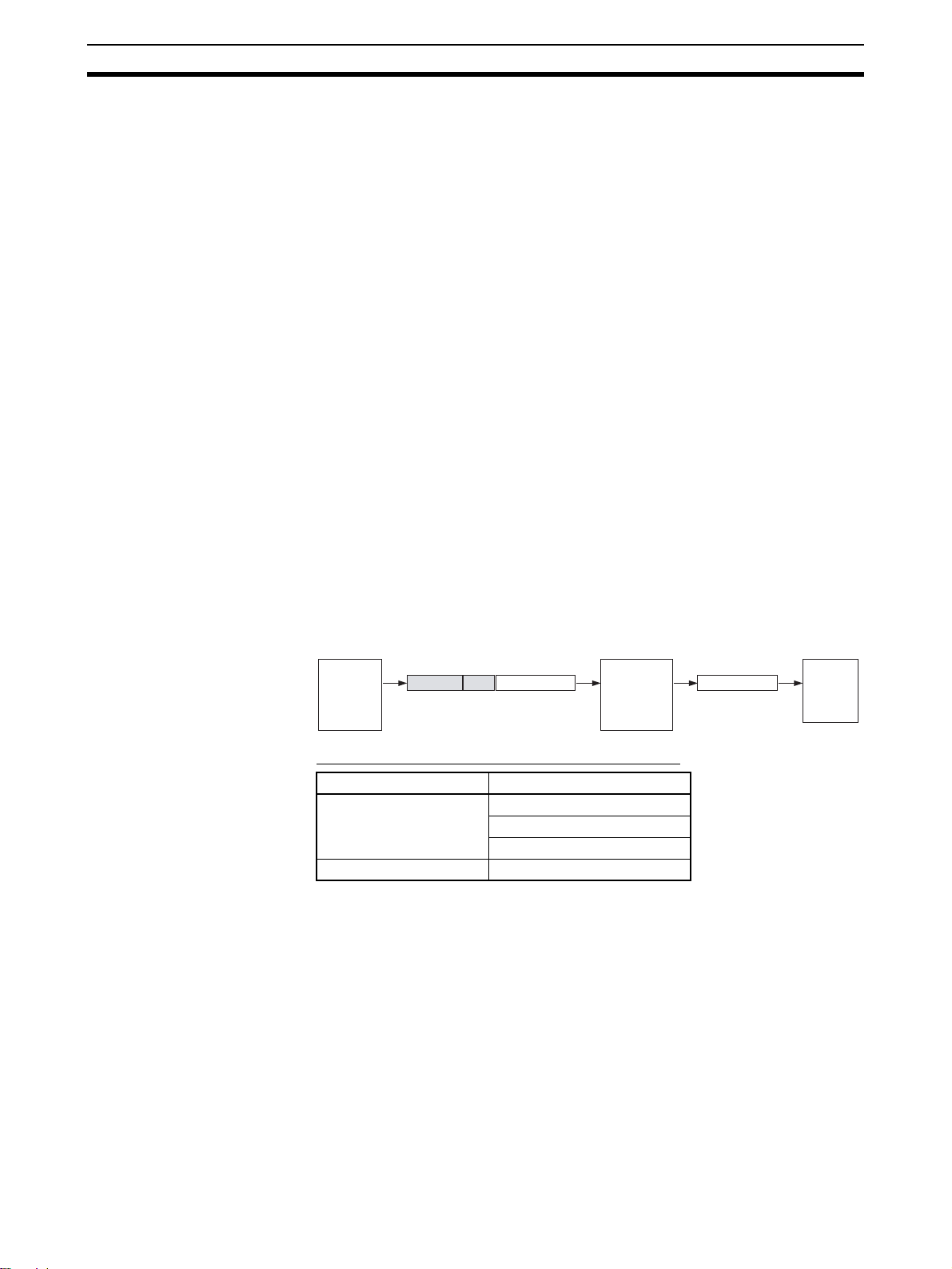
Serial Gateway Overview Section 3-6
• With routing tables that treat serial communications path as a network:
Network address corresponding to serial port in the routing tables.
• Without routing tables that treat serial communications path as a network: Network address for specifying actual remote PC.
• Remote destination node address (DA1)
• With routing tables that treat serial communications path as a network:
00 hex (local PC’s internal communications) (For serial-to-serial-to-serial conversion, increment the Host Link unit number by 1.)
• Without routing tables that treat serial communications path as a network: Node address for specifying actual remote PC (For serial-to-serial-to-serial conversion, increment the Host Link unit number by 1.)
• Remote destination unit address (DA2)
Unit address of serial port
(2) The contents of the CompoWay/F command enclosed in the FINS mes-
sage that is sent is as follows:
Node number + subaddress + SID + command text (ASCII must be used.)
STX, ETX+BCC are not required when sending FINS. They are added
automatically for serial communications.
3-6-4 Converting FINS to Modbus-RTU
Modbus-RTU Slave-compatible devices (including OMRON Inverters) connected serially to a PC via Modbus-RTU can be accessed from the PC or PT
using Modbus-RTU commands enclosed in FINS messages.
• Sent FINS message: FINS header + FINS command code 2804 hex +
Modbus-RTU command
• Message after conversion: Modbus-RTU command
CPU Unit
(CMND(490)
instruction) or
PT (Programmable Terminal)
FINS header
Modbus-RTU command encapsulated
using FINS command 2804 hex
(Via network or CPU bus)
Modbus-RTU command
2804
Serial Communications
Unit/Board
Modbus-RTU command
Modbus-RTU command
(RS-232C or RS-422A/485)
Modbus-RTU
Slavecompatible
device
(OMRON
Inverter, etc.)
Modbus-RTU Slave-compatible OMRON Devices
Type Model series
Inverters 3G3JV
3G3MV
3G3RV
Temperature Controllers E5CN (New version)
70
Page 93

Serial Gateway Overview Section 3-6
System Configuration Patterns
Sending FINS Messages Using CMND(490) in CPU Unit’s Ladder Program
The Board/Unit converts the FINS messages to Modbus-RTU protocol for
sending in this operation.
Access from CPU Unit (on the Same PC)
CPU Bus-to-Serial Details Routing tables to treat serial
communications path as network
Serial Communications Unit/Board
CPU Unit
Protocol
conversion
FINS header
Modbus-RTU
command
Modbus-RTU
Slave device
(e.g, OMRON
Inverter)
2804
CMND(490)
FINS message
Modbus-RTU
command
RS-485 (Modbus-RTU)
OMRON Inverters connected serially to
the Serial Communications Board/Unit
using Modbus-RTU can be accessed from
a CPU Unit in the same PC.
Access from CPU Unit (on Network PC)
FINS message-to-Serial Details Routing tables to treat serial
OMRON Inverters connected serially to
the Serial Communications Board/Unit
using Modbus-RTU can be accessed from
a CPU Unit in a PC connected to the network.
FINS header
Serial Communications Unit/Board
CPU Unit
Protocol
conversion
Modbus-RTU
command
Modbus-RTU
Slave device
(e.g, OMRON
Inverter)
CMND(490)
FINS message
Modbus-RTU
2804
command
RS-485 (Modbus-RTU)
Network (Ethernet,
Controller Link,
DeviceNet)
Optional
communications path as network
Optional
71
Page 94

Serial Gateway Overview Section 3-6
Executing Smart Active Parts Using an NS-series PT (Sending Internal FINS Messages)
The Board/Unit converts the FINS messages to Modbus-RTU protocol for
sending in this operation.
Access from PT on Ethernet or
serial NT Link
NS-series PT
Smart Active Parts
FINS message (sent internally)
Ethernet
Serial Communications Unit/Board
Protocol
conversion
CPU Unit
Modbus-RTU
command
ORMON Inverter
2804FINS header
Modbus-RTU
command
RS-485 (Modbus-RTU)
Note When the NS-series PT is con-
nected serially to the PC using
serial communications mode
(1:N NT Links), and the NSseries PT sends FINS commands encapsulated in NT Link
commands using Smart Active
Parts, the CPU Unit removes the
NT Link header, etc. from the
received command, converting it
to a FINS command, and transfers the command to the Serial
Communications Board/Unit.
The Serial Communications
Board/Unit uses the Serial Gateway to convert the command into
the specified protocol. This operation enables serially connected
devices to access the Serial
Communications Board/Unit
from Smart Active Parts using an
NS-series PT.
Details Routing tables to treat serial
Access via serial communications using
Modbus-RTU is possible from a PT connected to the network by executing a
Smart Active Part that is connected serially, which automatically sends an internal
FINS command.
communications path as network
Optional
72
Note (1) The FINS header contains the following information.
• Remote destination network address (DNA): Same as for CompoWay/F.
• Remote destination node address (DA1): Same as for CompoWay/F.
• Remote unit address (DA2): Same as for CompoWay/F.
(2) The contents of the Modbus-RTU command enclosed in the FINS mes-
sage that is sent is as follows:
Slave address (binary) + FUNCTION code (binary) + Communications
data (binary)
Start and CRC+End are not required when sending FINS. They are added automatically for serial communications.
Page 95

Serial Gateway Overview Section 3-6
3-6-5 Converting from FINS to Modbus-ASCII
Modbus-ASCII Slave-compatible devices connected serially to a PLC via
Modbus-ASCII can be accessed from the PLC using Modbus-ASCII commands enclosed in FINS messages.
• Sent FINS message: FINS header + FINS command code 2805 hex +
Modbus-ASCII command
• Message after conversion: Modbus-ASCII command
CPU Unit
(CMND(490)
instruction)
FINS message
FINS header Modbus-ASCII command
Modbus-ASCII command encapsulated
using FINS command 2805 hex
2805
(Via network or CPU bus)
Serial Communications
Unit/Board
(RS-232C or RS-422A/485)
System Configuration Patterns
Sending FINS Messages Using CMND(490) in CPU Unit’s Ladder Program
The Board/Unit converts the FINS messages to Modbus-ASCII protocol for
sending in this operation.
Access from CPU Unit (on the Same PLC)
CPU Bus-to-Serial Details Routing tables to treat serial
communications path as network
Serial Communications Unit/Board
CPU Unit
Protocol
conversion
FINS header
Modbus-ASCII command
Modbus-ASCII
Slave device
2805
CMND(490)
FINS message
Modbus-ASCII command
RS-485 (Modbus-ASCII)
Slaves connected serially to the Serial
Communications Board/Unit using Modbus-ASCII can be accessed from a CPU
Unit in the same PLC.
Optional
Modbus-ASCII command
Modbus-ASCII command
ModbusASCII Slavecompatible
device
Access from CPU Unit (on Network PLC)
FINS message-to-Serial Details Routing tables to treat serial
communications path as network
FINS header
Serial Communications Unit/Board
CPU Unit
Protocol
conversion
Modbus-ASCII
command
Modbus-ASCII
Slave device
CMND(490)
FINS message
Modbus-ASCII
2805
command
Network (Ethernet, Controller
Link, DeviceNet)
RS-485 (Modbus-ASCII)
Slaves connected serially to the Serial
Communications Board/Unit using Modbus-ASCII can be accessed from a CPU
Unit in a PLC on the network.
Optional
Note (1) The FINS header contains the following information.
• Remote destination network address (DNA): Same as for CompoWay/F.
• Remote destination node address (DA1): Same as for CompoWay/F.
• Remote unit address (DA2): Same as for CompoWay/F.
(2) The contents of the Modbus-ASCII command enclosed in the FINS mes-
sage that is sent is as follows:
Slave address (ASCII) + FUNCTION code (ASCII) + Communications
data (ASCII)
73
Page 96

Serial Gateway Overview Section 3-6
The header “:” (3A hex) and LRC+CR/LF are not required when sending
FINS. They are added automatically for serial communications.
3-6-6 Converting from FINS to Host Link FINS
A PC slave that is connected serially to the PC master via Host Link can be
accessed from the PC master or personal computer (see note) using FINS
messages. Accessing a device on another network via Host Link (serial communications) is also possible by using FINS messages. By converting the
FINS to Host Link FINS, the PC can function as a Host Link master.
Note Applications such as CX-Programmer or CX-Protocol that use CX-
Server as a communications driver.
• Sent FINS message: FINS header + User-specified FINS command (see
note 1)
• Message after conversion: FINS command enclosed in Host Link header
and terminator (see note 2)
CX-Programmer or other
application
using CXServer or
CPU Unit
(CMND(490))
FINS message
User-specified
FINS command
(Via serial, network,
or CPU bus)
Serial Communications
Unit/Board
Host Link header
FINS command encapsulated using Host Link
Host Link FINS command
User-specified FINS
command
(RS-232C or RS-422A/485)
Terminator
OMRON PC (CS/CJ
Series, CVM1/CV
Series)
(To other network)
FINS command
System Configuration Patterns
Access from CX-Programmer (Sending Internal FINS Messages)
The Board/Unit converts the FINS messages to Host Link FINS for sending in
this operation.
Access from Serially Connected CX-Programmer
Serial-to-Serial Details Routing tables to treat serial
Serial Communications Unit/Board
CPU Unit
Protocol
conversion
Used as Host Link Master
Peripheral or RS-232C port
Host Link header
User-specified
Host Link header Terminator
FINS command
CX-Programmer, etc.
User-specified
Terminator
FINS command
RS-422A/485 (Host Link)
CS/CJ-series or CVM1/CV-series PC (Host Link Slave)
Use the following method to access the serially (serial-to-serial) connected
PC from the CX-Programmer.
Personal computers (e.g., CXProgrammer) connected serially (via tool bus or Host Link)
to the PC master can access a
PC slave that is connected
serially to the PC master via
Host Link.
Optional
communications path as network
74
Page 97

Serial Gateway Overview Section 3-6
System Configuration Example
Serial Communications Board/Unit with unit Ver. 1.2 or later
(Select SCU (Unit 0 to 15) in the UNIT field.)
Set the relay PC.
(Select in the Change PLC Dialog Box.)
Serial Gateway function
port (Select port 1/2 in the
PORT field according to
the calculated address.)
Serial
Gate-
way
Host Link FINS
PC name: PC2
1,2,3... 1. Register the PC to be connected serially (using Host Link FINS) in the
project gateway (e.g., PC2).
2. In the Change PLC Dialog Box of the target PC (e.g., PC1), select the relay
PC (gateway PC) in the Network Type pull-down menu (e.g., [PC2] (See
note.)) and click the Settings Button to the right of the Network Type pull-
down menu.
Note The PC name enclosed in square brackets (e.g., [PC2]) indicates the
gateway PC.
CX-Programmer Ver. 5.0 or later
Network type: Select [PC2].
Select the Use SYSWAY with the port option
in the Host Link (SYSWAY) settings.
PC name: PC1
Target PC Host Link unit number
Enter the Host Link unit number in the
Host Link Unit Number field for the target
PC in the Host Link (SYSWAY) settings.
Select the PC to be used as the
relay PC (e.g., [PC2]) in the
Network Type pull-down menu.
3. The Network Settings Dialog Box will be displayed. Click the Guide for Se-
rial Gateway Button.
4. The Serial Gateway Guide Dialog Box will be displayed.
Select the unit and the port number under the Calculate Address Area, the
serial port number address is automatically calculated in the Calculated
Address Field.
Select the Use SYSWAY with the port option, and enter the actual Host
Link unit number for the target (communications partner) PC in the Host
Link Unit Number field (see note).
Finally, click the Apply Button.
75
Page 98

Serial Gateway Overview Section 3-6
(
)
The Serial
Communications port
address is automatically
Select the Unit.
Select the port.
Select this option.
Enter the unit number for the
actual Host Link (values are
incremented by 1 automatically).
Note When using the CX-Programmer, enter the actual Host Link unit number. Do
not add 1 to the value. The CX-Programmer will automatically add 1 internally.
Access from CX-Programmer Connected to Network
Network-to-Serial Details Routing tables to treat serial
Personal computers (e.g., CX-Programmer) connected through the
network to the PC master can
access a PC slave that is connected serially to the PC master
via Host Link.
FINS message
User-specified
FINS command
Serial Communications Unit/Board
CPU Unit
CX-Programmer, etc.
Network (Ethernet, Controller
LInk, DeviceNet)
calculated.
communications path as network
Required
Protocol
conversion
Used as Host
Link Master
User-specified
Host Link header
CS/CJ-series or CVM1/CV-series PC
FINS command
Terminator
RS-422A/485
(Host Link)
Host Link Slave
Note This configuration can be connected to other networks, as shown be-
low.
Network-to-Serial-to-Network Details Routing tables to treat serial
CX-Programmer, etc.
Personal computers (e.g., CX-Programmer) connected through the
network to the PC master can
FINS message
User-specified
FINS command
Serial Communications Unit/Board
Protocol
conversion
Used as Host
Link Master
Network (Ethernet,
Controller LInk, DeviceNet)
CPU Unit
User-specified
Host Link header Terminator
FINS command
User-specified
FINS command
RS-422A/485
(Host Link)
CS/CJ-series
or CVM1/CVseries PC
(Host Link
Slave)
Network (Ethernet,
Controller LInk,
DeviceNet)
access a PC on another network
via a PC slave that is connected
serially to the PC master via Host
Link.
communications path as network
Required
76
Page 99

Serial Gateway Overview Section 3-6
Sending FINS Messages or Sending/Receiving Data Using CMND(490), RECV(098),
SEND(090) in the CPU Unit’s Ladder Program
The Board/Unit converts the FINS messages to Host Link FINS in this operation.
CPU bus-to-Serial Details Routing tables to treat serial
Serial Communications Unit/Board
CPU Unit
FINS
message
Protocol
conversion
Used as Host
Link Master
User-specified FINS
command
Host Link header
CS/CJ-series or CVM1/CV-series PC (Host Link Slave)
Network-to-Serial Details Routing tables to treat serial
Serial Communications Unit/Board
CPU Unit
Protocol
conversion
Host Link header
Used as Host
Link Master
CS/CJ-series or CVM1/CV-series PC (Host Link Slave)
User-specified
FINS command
User-specified
FINS command
CMND(490)
or
SEND(090)/
RECV(098)
Terminator
Terminator
CMND(490)
or
SEND(090)/RECV(098)
FINS message
User-specified
FINS command
Network (Ethernet,
Controller LInk, DeviceNet)
RS-422A/485
(Host Link)
Access from CPU Unit (on the Same PC
Slave PCs connected serially to
the Serial Communications Board/
Unit using Host Link can be
accessed from the CPU Unit in the
same PC.
RS-422A/485
(Host Link)
Access from CPU Unit (on Network PC)
Slave PCs connected serially to
the Serial Communications Board/
Unit using Host Link can be
accessed from a CPU Unit in a PC
connected to the network.
)
communications path as network
Optional
communications path as network
Required
Note This configuration can be connected to other networks, as shown be-
low
Network-to-Serial-to-Network Details Routing tables to treat serial
communications path as network
Serial Communications Unit/Board
CPU Unit
Protocol
conversion
Host Link header
Used as Host
Link Master
User-specified
FINS command
User-specified
FINS command
CMND(490)
or
SEND(090)/
RECV(098)
FINS message
User-specified
FINS command
Network (Ethernet, Controller
LInk, DeviceNet)
Terminator
Network (Ethernet,
Controller LInk, DeviceNet)
RS-422A/485
(Host Link)
CS/CJ-series or
CVM1/CV-series PC
(Host Link Slave)
CPU Units in PCs connected to
the network can access a PC on
another network via a PC slave
that is connected serially to the
Serial Communications Board/Unit
via Host Link.
Required
Note (1) The FINS header contains the following information.
77
Page 100

Serial Gateway Overview Section 3-6
• Remote destination network address (DNA)
• With routing tables that treat serial communications path as a network:
Network address corresponding to serial port in the routing tables.
• Without routing tables that treat serial communications path as a network: Unit address of serial port.
• Remote destination node address (DA1)
• With routing tables that treat serial communications path as a network:
Unit number for Host Link incremented by 1 (1 to 32)
• Without routing tables that treat serial communications path as a network: Unit number for Host Link incremented by 1 (1 to 32)
• Remote destination unit address (DA2)
Any unit address except that for the serial port (The destination for the
FINS message must not be the serial port of the Board/Unit.)
• FINS command code: Any
(2) When creating Host Link FINS command frames using the CMND(490)
instruction, always set the unit number for Host Link incremented by one
(1 to 32) for the remote destination (send destination) node address
(word C+3, bits 08 to 15 of the CMND(490) instruction). Do not set the
unit number of the actual Host Link slave (0 to 31). Using the Host Link
unit number without incrementing by one will access the PC with the entered Host Link unit number less one.
For example, specify the remote PC with Host Link unit number 2 by entering 3 for the remote destination node address. If 2 is entered, the PC
with Host Link unit number 1 will be accessed.
To access a PC on a Host Link FINS network using the Serial Gateway
from CX-Programmer, however, enter the actual Host Link unit number,
without incrementing by one. (Select Change PLC, click the Display Se-
rial Gateway Guide Button, and set unit number in the Host Link
SYSWAY Settings field of the Serial Gateway Guide Dialog Box.
(3) The contents of the FINS command enclosed by the Host Link header
and terminator is as follows:
@+Host Link unit number + Host Link header FA + FINS header + FINS
command + Text + FCS + * + CR
3-6-7 Treating Serial Communications Paths as Networks
When the Serial Gateway is executed, routing tables are either required or
optional as follows:
• Routing tables are required to treat a serial communications path as a
network when converting FINS messages to Host Link FINS for serial
conversion via the network.
• Under other conditions, routing tables are optional.
The details are provided in the following tables.
78
 Loading...