

Page 1

SYSMAC CS/CJ-series
CS1W-PRM21
CJ1W-PRM21
PROFIBUS-DP Master Units
Operation Manual (Draft)
Produced November 17, 2003
Page 2

iv
Page 3

Notice:
OMRON products are manufactured for use by a trained operator and only for the purposes described
in this manual.
The following conventions are used to classify and explain the precautions in this manual. Always
heed the information provided with them.
!DANGER Indicates information that, if not heeded, is likely to result in serious injury or loss of life.
!WARNING Indicates information that, if not heeded, c ould possibly result in serious injur y or loss of
life.
!Caution Indicates information that, if not heeded, could possibly result in minor or relatively serious
injury, damage to the product or faulty operation.
OMRON Product References
All OMRON products are capitalized in this manual. The first letter of the word
when it refers to an OMRON product, regardless of whether it appears in the proper name of the product.
The abbreviation
and is abbreviated as Wd in the documentation.
The abbreviation
Visual Aids
The following headings appear in the left column of the manual to help you locate different types of
information.
Unit
is also cap italiz ed
Ch
appears in som e displays and on some OM RON products. It often means
PLC
means Programmable Logic Controller.
Note Indicates information of par ticular interest for efficient and convenient opera-
tion of the product.
1, 2, 3...Indicates various lists such as procedures, checklists etc.
word
v
Page 4

Trademarks and Copyrights
f
Profibus is a registered trademark of the Profibus International Organization.
Microsoft Windows, Windows 95, Windows 98, Windows NT, Windows 2000, and Windows XP are
registered trademarks of the Microsoft Corporation.
AnyBus is a registered trademark of the Hjassber MicroSystems Sweden
Sycon and CIF are registered trademarks of Hilscher GmbH
Other product names and company names in this manual are trademarks or registered trademark s of
their respective companies.
The copyright of the Profibus Master Unit belongs to OMRON Corporation.
OMRON, 2003
All rights reserv ed. No part of this publica tion may be reproduced, stored in a retrieval system, or transmitted, in any form, or
by any means, mechanical, electronic, photocopying, recording, or otherwise, without the prior written permission o
OMRON.
No patent liability is assumed with respect to the use of the information contained herein. Moreover, because OMRON is constantly striving to improve its high-quality products, the information contained in this manual is subject to change without
notice. Every precaution has been taken in the preparation of this manual. Nevertheless, OMRON assumes no responsibility
for errors or omissions. Neither is any liability assumed for damages resulting from the use of the information contained in
this publication.
vi
Page 5

TABLE OF CONTENTS
About this Manual . . . . . . . . . . . . . . . . . . . . . . . . . . . . . . . . . ix
PRECAUTIONS . . . . . . . . . . . . . . . . . . . . . . . . . . . . . . . . . . . xi
1 Intended Audience . . . . . . . . . . . . . . . . . . . . . . . . . . . . . . . . . . . . . . . . . . . . . . . . . . . . . . . . . xii
2 General Precautions. . . . . . . . . . . . . . . . . . . . . . . . . . . . . . . . . . . . . . . . . . . . . . . . . . . . . . . . xii
3 Safety Precautions . . . . . . . . . . . . . . . . . . . . . . . . . . . . . . . . . . . . . . . . . . . . . . . . . . . . . . . . . xii
4 Operating Environment Precautions . . . . . . . . . . . . . . . . . . . . . . . . . . . . . . . . . . . . . . . . . . . xiii
5 Application Precautions. . . . . . . . . . . . . . . . . . . . . . . . . . . . . . . . . . . . . . . . . . . . . . . . . . . . .xiii
6 Conformance to EC Directives . . . . . . . . . . . . . . . . . . . . . . . . . . . . . . . . . . . . . . . . . . . . . . . xv
SECTION 1
Features and Specifications . . . . . . . . . . . . . . . . . . . . . . . . . . 1
1-1 Overview of PROFIBUS . . . . . . . . . . . . . . . . . . . . . . . . . . . . . . . . . . . . . . . . . . . . . . . . . . . . 2
1-2 Setting up a PROFIBUS-DP Network. . . . . . . . . . . . . . . . . . . . . . . . . . . . . . . . . . . . . . . . . . 7
1-3 PROFIBUS-DP Master Unit . . . . . . . . . . . . . . . . . . . . . . . . . . . . . . . . . . . . . . . . . . . . . . . . . 9
1-4 CX-Profibus Configurator . . . . . . . . . . . . . . . . . . . . . . . . . . . . . . . . . . . . . . . . . . . . . . . . . . .16
1-5 Basic Operating Procedure . . . . . . . . . . . . . . . . . . . . . . . . . . . . . . . . . . . . . . . . . . . . . . . . . .20
SECTION 2
Installation and Wiring . . . . . . . . . . . . . . . . . . . . . . . . . . . . . 23
2-1 Unit Components. . . . . . . . . . . . . . . . . . . . . . . . . . . . . . . . . . . . . . . . . . . . . . . . . . . . . . . . . . 24
2-2 Installing the PROFIBUS-DP Master Unit . . . . . . . . . . . . . . . . . . . . . . . . . . . . . . . . . . . . . . 28
2-3 Initial Setup Procedure . . . . . . . . . . . . . . . . . . . . . . . . . . . . . . . . . . . . . . . . . . . . . . . . . . . . . 31
2-4 Setting up a Network . . . . . . . . . . . . . . . . . . . . . . . . . . . . . . . . . . . . . . . . . . . . . . . . . . . . . . . 33
2-5 Defining PROFIBUS-DP in the Software . . . . . . . . . . . . . . . . . . . . . . . . . . . . . . . . . . . . . . . 37
SECTION 3
Configuration Software . . . . . . . . . . . . . . . . . . . . . . . . . . . . . 39
3-1 Installation . . . . . . . . . . . . . . . . . . . . . . . . . . . . . . . . . . . . . . . . . . . . . . . . . . . . . . . . . . . . . . . 40
3-2 CX-Profibus. . . . . . . . . . . . . . . . . . . . . . . . . . . . . . . . . . . . . . . . . . . . . . . . . . . . . . . . . . . . . . 47
3-3 PROFIBUS-DP Master DTM . . . . . . . . . . . . . . . . . . . . . . . . . . . . . . . . . . . . . . . . . . . . . . . . 60
3-4 Generic Slave Device DTM. . . . . . . . . . . . . . . . . . . . . . . . . . . . . . . . . . . . . . . . . . . . . . . . . . 77
SECTION 4
Allocated CIO and DM Words . . . . . . . . . . . . . . . . . . . . . . . 83
4-1 Overview of Word Allocations . . . . . . . . . . . . . . . . . . . . . . . . . . . . . . . . . . . . . . . . . . . . . . . 84
4-2 Allocated CIO Area Words . . . . . . . . . . . . . . . . . . . . . . . . . . . . . . . . . . . . . . . . . . . . . . . . . . 86
SECTION 5
Fins Commands and Responses. . . . . . . . . . . . . . . . . . . . . . . 99
5-1 FINS Commands and Responses. . . . . . . . . . . . . . . . . . . . . . . . . . . . . . . . . . . . . . . . . . . . . . 100
vii
Page 6

TABLE OF CONTENTS
5-2 Command / Response Reference. . . . . . . . . . . . . . . . . . . . . . . . . . . . . . . . . . . . . . . . . . . . . . 102
SECTION 6
Operation. . . . . . . . . . . . . . . . . . . . . . . . . . . . . . . . . . . . . . . . . 109
6-1 Introduction . . . . . . . . . . . . . . . . . . . . . . . . . . . . . . . . . . . . . . . . . . . . . . . . . . . . . . . . . . . . . . 110
6-2 Setting up a network . . . . . . . . . . . . . . . . . . . . . . . . . . . . . . . . . . . . . . . . . . . . . . . . . . . . . . . 11 0
6-3 Configuring the Slave Stations . . . . . . . . . . . . . . . . . . . . . . . . . . . . . . . . . . . . . . . . . . . . . . . 115
6-4 Configuring the Master . . . . . . . . . . . . . . . . . . . . . . . . . . . . . . . . . . . . . . . . . . . . . . . . . . . . . 119
SECTION 7
Troubleshooting and Maintenance . . . . . . . . . . . . . . . . . . . . 127
7-1 Overview . . . . . . . . . . . . . . . . . . . . . . . . . . . . . . . . . . . . . . . . . . . . . . . . . . . . . . . . . . . . . . . . 128
7-2 Troubleshooting Using LED Indicators. . . . . . . . . . . . . . . . . . . . . . . . . . . . . . . . . . . . . . . . . 129
7-3 Troubleshooting I/O Communication . . . . . . . . . . . . . . . . . . . . . . . . . . . . . . . . . . . . . . . . . . 135
7-4 Troubleshooting Using Error Status . . . . . . . . . . . . . . . . . . . . . . . . . . . . . . . . . . . . . . . . . . . 138
7-5 Troubleshooting using the Error Log. . . . . . . . . . . . . . . . . . . . . . . . . . . . . . . . . . . . . . . . . . . 141
7-6 Troubleshooting FINS Commands . . . . . . . . . . . . . . . . . . . . . . . . . . . . . . . . . . . . . . . . . . . . 143
7-7 Maintenance. . . . . . . . . . . . . . . . . . . . . . . . . . . . . . . . . . . . . . . . . . . . . . . . . . . . . . . . . . . . . . 144
7-8 Replacing the Unit. . . . . . . . . . . . . . . . . . . . . . . . . . . . . . . . . . . . . . . . . . . . . . . . . . . . . . . . . 145
Appendices
A Bus Parameters . . . . . . . . . . . . . . . . . . . . . . . . . . . . . . . . . . . . . . . . . . . . . . . . . . . . . . . . . . . 147
B Slave Diagnostics Message . . . . . . . . . . . . . . . . . . . . . . . . . . . . . . . . . . . . . . . . . . . . . . . . . . 151
C Memory Card Backup Functions . . . . . . . . . . . . . . . . . . . . . . . . . . . . . . . . . . . . . . . . . . . . . 161
D I/O Data Conversions . . . . . . . . . . . . . . . . . . . . . . . . . . . . . . . . . . . . . . . . . . . . . . . . . . . . . . 163
E Configurator Error and Warning Messages . . . . . . . . . . . . . . . . . . . . . . . . . . . . . . . . . . . . . 167
Index. . . . . . . . . . . . . . . . . . . . . . . . . . . . . . . . . . . . . . . . . . . . . 173
Revision History . . . . . . . . . . . . . . . . . . . . . . . . . . . . . . . . . . . 175
viii
Page 7

About this Manual
This manual describes the CS1W-PRM21 and CJ1W-PRM21 PROFIBUS-DP Master Units. It also
describes how to install and operate them. Both Units ser ve the sam e purpose: enable devices of various manufacturers to intercommunicate without making any special interface adaptations. They are
technically the same; they differ only in their physical dimensions and weight and the way they are connected to the backplane.
Please read this manual carefully so that you understand the i nformation provided before installing or
using the PROFIBUS-DP Master Unit. Start with the precautions in the following section. They
describe the operating environment and application safety measures which must be observed prior to
and when using the PROFIBUS-DP Master Unit.
The sections of this manual are as follows:
Section 1
Section 2
Section 3
Section 4
Section 5
Section 6
Section 7
The
introduces the PROFIBUS-DP Master Units and CX-Profibus.
describes the installation and setup of the PROFIBUS-DP Master Units.
describes the installation of CX-Profibus and provides a overview.
describes how the Units interface to the PLC CPU.
describes the FINS commands suppor t ed by the PROFIBUS Master Units.
describes the operational aspects of the PROFIBUS Master Units.
provides procedures for troubleshooting the PROFIBUS-DP network and the Units.
Appendices
contain information supplementar y to the information in the main body of the man-
ual. They are referred to in the various sections as required.
Manual Products Contents Cat. No.
CS-series
Programmab le Controllers
Operation Manual
CJ-series
Programmab le controllers
operation Manual
CS/CJ-series
Programmab le Controllers
Programming Manual
CS/CJ-series
Programmab le Controllers
Instructions Reference Manual
CS/CJ Series Communication
Commands Reference Manual
CX-Programmer
Operation Manual
CX-Server
Run Time User Manual
SYSMAC CS-series
CS1G/H-CPU@@-E
SYSMAC CJ-series
CJ1G-CPU@@
SYSMAC CS/CJ-series
CS1G/H-CPU@@-E, CJ1GCPU@@
SYSMAC CS/CJ-series
CS1G/H-CPU@@-E, CJ1GCPU@@
SYMAC CS1G/H-CPU@@-E
CPU Units
SYSMAC WS02-CXP@@-E
CX-Programmer
CX-Server Provides inf ormation on ho w to use the
Describes the installation and operation of the CS-series PLCs.
Describes the installation and operation of the CJ-series PLCs.
Describes the ladder diagram programming instruc tions supported by
CS/CJ-series PLCs.
Describes the ladder diagram programming instruc tions supported by
CS-series and CJ-series PLCs.
Describes the C-serie s (Host Li nk) and
FINS communications comman ds
used with CS/CJ-series PLCs.
Provides inf ormation on how to use th e
CX-Programmer, programming software which supports CS1/CJ1-series
PLCs.
CX- S e rver c ommun icati on dri ver soft ware which supports CS1/CJ1-series
PLCs.
W339-E1-@
W393-E1-@
W394-E1-@
W340-E1-@
W342-E1-@
W414-E1-@
W391-E2-@
ix
Page 8

Manual Products Contents Cat. No.
C200H-series PROFIBUS-DP
Master Units
Operation Manual
CJ-series PROFIBUS-DP
Slave unit
Operation Manual
GT1-series PROFIBUS-DP
Multiple I/O Terminal
Operation Manual
C200H-series PROFIBUS-DP
Slave unit
Operation Manual
F150-series PROFIBUS-DP
Vision Sensor
Operation Manual
CS/CJ-seri es Ethernet Units
Operation Manual
CS/CJ-series Serial Communi cations Boards and Serial
Communications Units
Operation Manual
CS/CJ1-seri es D evicenet Units
Operation Manual
SYSMAC C200H-series
C200HW-PRM21
SYSMAC CJ1-series
CJ1W-PRT21
PRT1-COM & GT1-series Describes the Installation and Opera-
SYSMAC C200H-series
C200HW-PR T21 PROFIBUS-DP
Slave unit
F150-C15E-3-PRT21 PROFIBUS-DP Vision Sensor
SYSMAC CS/CJ-series
CS1W-ETN01/ETN11
CJ1W-ETN11 Ethernet Units
SYSMAC CS/CJ-series
CS1W-SCB21/41, CS1WSCU21, CJ1W-CSU41
SYSMAC CS/CJ1-series
CS1W-DRM21/CJ1W-DRM21
Describes the Installation and Operation of the C200HW-PRM 21 PROFIBUS-DP Master Units.
Describes the Installation and Operation of the CJ1W-P RT21 PROFIBUSDP Slave Units.
tion of the PROFIBUS-DP PRT1-CO M
and GT1-series I/O Units.
Describes the Installation and Operation of the C200HW-PRT21 PROFIBUS-DP Slave Units.
Describes the Installation and Operation of the F150 PROFIB US Vision
Sensor.
Describes the installation and operation of the CS1W- ETN01 (10Base-5),
CS1W-ETN11 (10Ba se-T), and CJ1WETN11 Ethernet Units.
Describes the use of Serial Communi cations Units and Boards to perform
serial communicat ions with external
devices.
Describes the Installation and Operation of the CS1W-DRM2 1/CJ1WDRM21 Devicenet units.
W349-E2-@
W408-E2-@
W900-E2-@
W901-E2-@
Z143-E1-@
W343-E1-@
W336-E1-@
W380-E2-@
!WARNING Failure to read and understand the information provided in this manual may result in per-
sonal injury or d eath, damage to the product, or product failure. Please read each section
in its entirety and be sure you understand the information provided in the section and
related sections before attempting any of the procedures or operations given.
x
Page 9

PRECAUTIONS
This section provides general precautions for using the PROFIBUS-DP Master Units, Programmable Controllers and
related de vices.
The information contained in this section is important for the safe and reliable operation of the PROFIBUS-DP
Master Units. You must read this section and understand the information contained before attempting to set up or
operate a PROFIB US -DP Mast er Unit and PLC system.
1 Intended Audience . . . . . . . . . . . . . . . . . . . . . . . . . . . . . . . . . . . . . . . . . . . . . xii
2 General Precautions . . . . . . . . . . . . . . . . . . . . . . . . . . . . . . . . . . . . . . . . . . . . xii
3 Safety Precautions. . . . . . . . . . . . . . . . . . . . . . . . . . . . . . . . . . . . . . . . . . . . . . xii
4 Operating Environment Precautions . . . . . . . . . . . . . . . . . . . . . . . . . . . . . . . . xiii
5 Application Precautions . . . . . . . . . . . . . . . . . . . . . . . . . . . . . . . . . . . . . . . . . xiii
6 Conformance to EC Directives . . . . . . . . . . . . . . . . . . . . . . . . . . . . . . . . . . . . xv
6-1 Applicable Directives . . . . . . . . . . . . . . . . . . . . . . . . . . . . . . . . . . . . xv
6-2 Concepts . . . . . . . . . . . . . . . . . . . . . . . . . . . . . . . . . . . . . . . . . . . . . . xv
6-3 Conformance to EC Directives. . . . . . . . . . . . . . . . . . . . . . . . . . . . . xv
xi
Page 10

Intended Audience
1 Intended Audience
This manual is intended for the following personnel, who must a lso have a
knowledge of electrical systems (an electrical engineer or the equivalent).
• Personnel in charge of installing FA systems.
• Personnel in charge of designing FA systems.
• Personnel in charge of managing FA systems and facilities.
2 General Precautions
The user must operate the prod uct according to the performance specifications described in the operation manuals.
Before using the product under conditions which are not described in the
manual or applying the product to nuclear control systems, railroad systems,
aviation systems, vehicles, combustion systems, medical equipment, amusement machines, safety equipment, and other systems, machines, and equipment that may have a serious influence on lives and property if used
improperly, consult your OMRON representative.
Make sure that the ratings and performance characteristics of the product are
sufficient for the systems, machines, and equipment, and be sure to provide
the systems, machines, and equipment with double safety mechanisms.
This manual provides information for programming and operating OMRON
PROFIBUS Master Units. Be sure to read this manual before attempting to
use the Unit and keep this manual close at hand for reference during operation.
1
!WARNING It is extremely important that all PLC Units be used for their specified pur-
poses and under the specified conditions, especially in applications that can
directly or indirectly affect human life. You must consult your OMRON representative before using a PLC System in the above-mentioned applications.
3 Safety Precautions
!WARNING Do not attempt to take any Unit apart while the power is being supplied. Doing
so may result in electric shock.
!WARNING Never touch any of the terminals while power is being supplied. Doing so may
result in serious electrical shock or electrocution.
!WARNING Do not attempt to disass em ble, repair, or modify any Units. Any attempt to do
so may result in malfunction, fire, or electric shock.
!WARNING Do not touch the Power Supply Unit while power is being supplied or imme di-
ately after power has been turned OFF. Doing so may result in electric shock.
!Caution Tighten the screws on the terminal block of the AC Power Supply Unit to the
torque specified in the operation manual. Loose screws may result in burning
or malfunction.
xii
Page 11

Operating Environment Precautions
!WARNING Execute online edits only after confirming that no adverse effects will be
caused by extending the cycle time. Otherwise, the input signals may not be
readable.
4 Operating Environment Precautions
!Caution Do not operate the Unit in the following places:
• Locations subject to direct sunlight.
• Locations subje ct to temperatures or humidities o utside the range specified in the specifications.
• Locations subject to condensation as the result of severe changes in temperature.
• Locations subject to corrosive or flammable gases.
• Locations subject to dust (especially iron dust) or salt.
• Locations subject to exposure to water, oil, or chemicals.
• Locations subject to shock or vibration.
Provide proper shielding when installing in the following locations:
• Locations subject to static electricity or other sources of noise.
• Locations subject to strong electromagnetic fields.
• Locations subject to possible exposure to radiation.
• Locations near to power supply lines.
4
!Caution The operating environment of the PLC system can have a large effect on the
longevity and reliability of the system. Unsuitable operating e nvironments c an
lead to malfunction, failure and other unforeseeable problems with the PLC
system. Ensure that the operating environment is within the specified conditions at installation time and remains that way during the life of the system.
Follow all installation instructions and precautions provided in the operation
manuals.
5 Appli c a tion Precautions
Observe the following precautions when using the PROFIBUS-DP Master
Unit.
!WARNING Failure to abide by the following precautions could lead to serious or possibly
fatal injury. Always heed these precautions.
• Always connect to a class-3 ground (100
Units.
!Caution Failure to abide by the following precautions could lead to faulty operation or
the PLC or the system or could damage the PLC or PLC Units. Always heed
these precautions.
Ω or less) when installing the
xiii
Page 12

Application Precautions
5
• Install double safety mechanisms to ensure safety against incorrect signals that may be produced by broken signal lines or momentary power
interruptions.
• When addin g a new station to th e network, make sure t hat the baud rate
is the same as other nodes.
• Use specified communications cables.
• Do not extend connection distances beyond the ranges given in the specifications.
• Always turn OFF the power supp ly to the personal c omp uter, Slaves, and
Communications Units before attempting any of the following.
• Mounting or dismounting the PROFIBUS-DP Master Unit, Power Supply Units, I/O Units, CPU Units, or any other Units.
• Assembling a Unit.
• Setting DIP switches or rotary switches.
• Connecting or wiring the cables.
• Connecting or disconnect ing connect ors.
• Be sure that the ter minal blocks, connectors, Memory Un its, expansion
cables, and other items with locking devices are properly locked into
place. Improper locking may result in malfunction.
• Be sure that all the mounting screws, terminal screws, Unit mounting
screws, and cable connector screws are tightened to the torque specified
in the relevant manuals. Incorrect tightening torque may result in malfunction.
• Leave the label attached to the Unit when wiring. Removing the label may
result in malfunction if foreign matter enters the Unit.
• Remove the label after the completion of wiring to ensure proper heat dissipation. Leaving the label attached may result in malfunction.
• Always use the power supply voltage specified in this manual.
• Double-check all the wiring and connection o f terminal blocks and connectors before mounting the Units.
• Use crimp terminals for wiring. Do not connect bare stranded wires
directly to terminals.
• Observe the following precautions when wiring the communications
cable.
• Separate the communications cables from the power lines or high-tension lines.
• Do not bend the communications c ables.
• Do not pull on the communications cables.
• Do not place heavy objects on top of the communications cables.
• Be sure to wire communications cable inside ducts.
• Use appropriate communications cables.
• Take appropriate measures to ensure that the specified power with the
rated voltage and frequency is supplied in places where the power supply
is unstable. An incorrect power supply may result in malfunction.
• Install external breakers and take other safety measures against short-circuits in external wiring. Ins ufficient safety measures against short-circuits
may result in burning.
• Double-check all the wiring and switch settings before turning ON the
power supply.
xiv
Page 13

Conformance to EC Directives
6
• Check the user program for proper execution before actually running it on
the Unit. Not checking the program may result in an unexpected operation.
• Confir m that no a dverse effect will occur in the s ystem before attempting
any of the following. Not doing so may result in an unexpected operation.
• Changing the ope rating mode of the PC.
• Force-setting/force-resetting any bit in memory.
• Changing the present value of any word or any set value in memory.
• After replacing Units, resume operation only after transferring to the new
CPU Unit and/or Special I/O Units the contents of the DM Area, HR Area,
and other data required for resuming operation. Not doing so ma y result in
an unexpected operation.
• When transporting or storing the product, cover the PCBs with electrically
conductive materials to prevent LSIs and ICs from being damaged by
static electricity, and also keep the product within the specified storage
temperature range.
• When transporting the Unit, use special packing boxes and protect it from
being exposed to excessive vibration or impacts during transpor tation.
• Do not attempt to disassemble, repair, or modify any Units.
6 Conformance to EC Directives
6-1 Applicable Directives
•EMC Directives
• Low voltage directive EN 61131-2:1994+A12:2000
6-2 Concepts
EMC Directives
OMRON Units complying with EC Directives also conform to related EMC
standards making them eas ie r t o i ncorporate in other Un its or machines. The
actual products have been checked for conformity to EMC standards. (See
the following note.) Whether the products conform to the standards in the system used by the customer, however, must be checked by the customer.
EMC-related performance of OMRON Units complying with EC Directives will
vary depending on the configuration, wiring, and other conditions of the equipment or control panel in which OMRON devices are installed. The customer
must, therefore, perform final checks to confir m th at units a nd th e overall system conforms to EMC standards.
Note Applicable EMS (Electromagnetic Susceptibility) and EMI (Electromagnetic
Interference standards in the EMC (Electromagnetic Compatibility) standards
are as follows:
Unit EMS EMI
CS1W-PRM21 EN 61000-6-2:2001 EN 61000-6-2:2001
CJ1W-PRM21
6-3 Conformance to EC Directives
PROFIBUS-DP Units that meet EC directives must be installed as follows:
xv
Page 14

Conformance to EC Directives
6
Units that meet EC directives also meet the common emission standard
(EN50081-2). The measures necessary to ensure that the standard is met will
vary with the overall configuration. You must therefore confirm that EC directives are met for the overall configuration, par ticularly any radiated emission
requirement (10 m).
xvi
Page 15

SECTION 1
Features and Specifications
This section provides an introductory overview of PROFIBUS, its functions and how to setup and configure a network. It
also addresses the PROFIBUS-DP Master Units and the Configurator, their features and specifications.
1-1 Overview of PROFIBUS. . . . . . . . . . . . . . . . . . . . . . . . . . . . . . . . . . . . . . . . . 2
1-1-1 Introduction. . . . . . . . . . . . . . . . . . . . . . . . . . . . . . . . . . . . . . . . . . . . 2
1-1-2 PROFIBUS Communication Protocol . . . . . . . . . . . . . . . . . . . . . . . 2
1-1-3 Device Types. . . . . . . . . . . . . . . . . . . . . . . . . . . . . . . . . . . . . . . . . . . 4
1-1-4 Bus Access Protocol . . . . . . . . . . . . . . . . . . . . . . . . . . . . . . . . . . . . . 4
1-1-5 Diagnostic functions . . . . . . . . . . . . . . . . . . . . . . . . . . . . . . . . . . . . . 5
1-1-6 Protection Mechanisms. . . . . . . . . . . . . . . . . . . . . . . . . . . . . . . . . . . 6
1-1-7 Network States . . . . . . . . . . . . . . . . . . . . . . . . . . . . . . . . . . . . . . . . . 6
1-2 Setting up a PROFIBUS-DP Network . . . . . . . . . . . . . . . . . . . . . . . . . . . . . . 7
1-2-1 Configuring the PROFIBUS-DP Master . . . . . . . . . . . . . . . . . . . . . 7
1-2-2 FDT/DTM Technology. . . . . . . . . . . . . . . . . . . . . . . . . . . . . . . . . . . 7
1-2-3 GSD file Technology . . . . . . . . . . . . . . . . . . . . . . . . . . . . . . . . . . . . 8
1-3 PROFIBUS-DP Master Unit . . . . . . . . . . . . . . . . . . . . . . . . . . . . . . . . . . . . . . 9
1-3-1 PROFIBUS-DP Master Unit Features . . . . . . . . . . . . . . . . . . . . . . . 9
1-3-2 Specifications . . . . . . . . . . . . . . . . . . . . . . . . . . . . . . . . . . . . . . . . . . 10
1-3-3 Comparison with Previous Model . . . . . . . . . . . . . . . . . . . . . . . . . . 14
1-4 CX-Profibus Configurator. . . . . . . . . . . . . . . . . . . . . . . . . . . . . . . . . . . . . . . . 16
1-4-1 CX-Profibus Features . . . . . . . . . . . . . . . . . . . . . . . . . . . . . . . . . . . . 16
1-4-2 Specifications . . . . . . . . . . . . . . . . . . . . . . . . . . . . . . . . . . . . . . . . . . 18
1-5 Basic Operating Procedure . . . . . . . . . . . . . . . . . . . . . . . . . . . . . . . . . . . . . . . 20
1-5-1 Overview. . . . . . . . . . . . . . . . . . . . . . . . . . . . . . . . . . . . . . . . . . . . . . 20
1-5-2 Preparations for Communications . . . . . . . . . . . . . . . . . . . . . . . . . . 21
1-5-3 Procedures Prior to Starting Communications . . . . . . . . . . . . . . . . . 21
1
Page 16

Overview of PROFIBUS
Section 1-1
1-1 Overview of PROFIBUS
1-1-1 Introduction
Standard EN50170r PROFIBUS (PROcess FIeldBUS) is an open fieldbus standard for a wide
range of applications in manufacturing, processing and building automation.
The Standard, EN 50170 (the Euronorm for field communications), to wh ich
PROFIBUS adheres, guarantees vendor independence and transparen cy of
operation. It enables devices of various manufacturers to intercommunicate
without having to make any special interface adaptations.
The PROFIBUS family comprises three mutually compatible versions:
PROFIBUS-FMS, PROFIBUS-DP a nd PROFIBUS -PA.
PROFIBUS-FMS FMS means Fieldbus Message Specification. This version is the general-pur-
pose solution for high-level extensive and complex communication tasks.
Powerful services open up a wide range of applications and provide great
flexibility.
PROFIBUS-DP DP means Decentralized Periphery. PROFIBUS-DP is optimized for high
speed and low-cost interfacing. It is specially designed for communication
between automation control systems and distributed I/O at the device level.
PROFIBUS-PA PA means Process Automation. It permits sensors and actuators to be con-
nected to one common bus even in areas where intrinsically safe products are
required. It also permits data and power to be supplied over the bus using
2-wire technology according the international standard IEC 1158-2.
Uniform Bus Access
Protocol
!Caution It is not possible to exchange one of these family members by another family
PROFIBUS-DP and PROFIBUS-FMS use the same transmission technology
and uniform bus access protocol. Consequently, both versions can be operated simultaneously on the s am e bus. FMS field devices, however, cannot be
controlled by DP masters and vice versa.
member. This will cause faulty operation.
The rest of this section describes the PROFIBUS-DP Protocol architecture.
1-1-2 PROFIBUS Communication Protocol
OSI reference model
ISO-7498
In general, the PROFIBUS communication protocol is based on the Open
System Interconnection (O SI) reference model in accordance with the international standard ISO-7498 (see the following illustration). It defines c ommunication layers 1, 2, and 7.
• Layer 1, the Physical Layer o f this model, defines the physical transmission characteristics.
• Layer 2, the Data Link Layer of this model, defines the bus access protocol. This protocol also includ es data security and the handling of transmission protocols and telegrams.
2
Page 17

Overview of PROFIBUS
Section 1-1
• Layer 7, the Application Layer of this model, defines the application functions. This Layer is only applic able to PROFIBUS-FMS.
DP-Profiles
DP-Extensions
User Interface Layer DP Basic Functions
(7) Applicati on Layer
(6) Presentation Layer
(5) Session Layer NOT DEFINED
(4) Transport Layer
(3) Network La yer
(2) Data Link Layer Fiel dbus Data Link (FDL)
(1) Physi cal Layer RS485 / Fibre Optics
OSI Layer 1, 2 and user
interface
PROFIBUS-DP uses layers 1 and 2, and the user interface. Layers 3 to 7 are
not defined for PROFIBUS-DP. The User interface Layer defines the interface
functions for specific application areas, i.e. the PROFIBUS-DP basic functions
and communication profiles.This streamlined architecture ensures fast and
efficient data transmission. The appl ication functions whi ch are available to
the user, as well as the system and device behaviour of the various PROFIBUS-DP device types, are specified in the user interface.
OSI Layer 1: T ransmission
medium
RS-485 transmission technology or fibre optics are available for transmission.
RS-485 transmission is the most frequently used transmission technology. Its
application area includes all areas in which h igh transmiss ion spee d and s imple inexpensive installation are required. PROFIBUS modules are interconnected by single twisted-pair shielded copper wires.
RS-485 tech n olo g y The RS-485 transmission technology is very easy to handle. Installation of the
twisted pair cable does not require expert knowledge. The bus structure permits addition and removal of stations or step-by-step commissioning of the
system without influencing the other stations. Later expansions have no effect
on stations which are already in operation.
RS-485 Transmission
speed
Transmission speeds between 9.6 kbit/s and 12 Mbit/s can be selected as
shown in the table below. One unique transmission speed must sel ected for
all devices on the bus (master and slave devices) when the system is commissioned
Baud rate (kbit/s) Distance / segment (m)
9.6 1200
19.2 1200
45.45 1200
93.75 1200
187.5 1000
500 400
1500 200
3000 100
6000 100
12000 100
Cable length The maximum cable length values depend on the transmission speed and are
based on type-A cable (see
Cable Type
). The length can be increased by the
use of repeaters.However, it is not recommended to use more than three
repeaters in series in a PROFIBUS network.
3
Page 18

Overview of PROFIBUS
Section 1-1
1-1-3 Device Types
PROFIBUS distinguishes between master devices and slave devices.
Master devices Master devices determine the data communication on the bus. A Master can
send messages without an external request, as long as it holds the bus
access right (the token). Masters are also referred to as active stations in the
PROFIBUS standard.
There are two types of master devices:
Class 1 Master (DPM1) A PROFIBUS-DP Class 1 Master (DPM1) device is a central controller, which
exchanges information with the decentralized stations (i.e. DP slaves) within a
specified message cycle.
Class 2 Master (DPM2) PROFIBUS-DP class 2 Master (DPM2) devices are programmers, configura-
tion devices or operator panels. They are used during commissioning, for configuration of the DP system, or for operation and monitoring pur poses.
The CS1W-PRM21 and the CJ1W-PRM21 are bot h PROFIBUS-DP Class 1
Master devices.
Slave devices Slave devices are peripheral devices. Typical slave devices include input/out-
put devices, valves, drives, and measuring transmitters. They do not have bus
access rights and they can only acknowledge received messages or send
messages to the master when requested to do so. Slaves are also called passive stations
Device profile To enable the exchange of devices from different vendors, the user data has
to have the same format. The PROFIBUS-DP protocol does not define the
format of user data, it is only responsible for the transmission of this data. The
format of user data may be def ined in so called pro files. Profiles can reduce
engineering costs since the meaning of application-related parameters is
specified precisely. Profiles have been defined for specific areas like drive
technology, encoders, and for sensors / actuators.
1-1-4 Bus Access Protocol
OSI Layer 2: Bus access
protocol
Medium Access Control The Medium Access Control (MAC) specifies the procedures which determine
Token passing The token passing procedure guarantees that the bus access right (the token)
The PROFIBUS bus access protocol is implemented by OSI layer 2. This protocol also includes data security and the ha ndling of the transmission protocols and messages.
when a station is permitted to transmit data. A token passing procedure is
used to handle the bus access between master devices, and a polling procedure is used to h andle the communication b etween a master device and its
assigned slave device(s).
is assigned to each master within a precisely defined time frame. The token
message, a special message for passing access rights from one master to the
next master, must be passed around the logical token ring - once to each
master - within a specified target rotation time. Each master executes this procedure automatically. A user can only change the target rotation time, but is
not recommended.
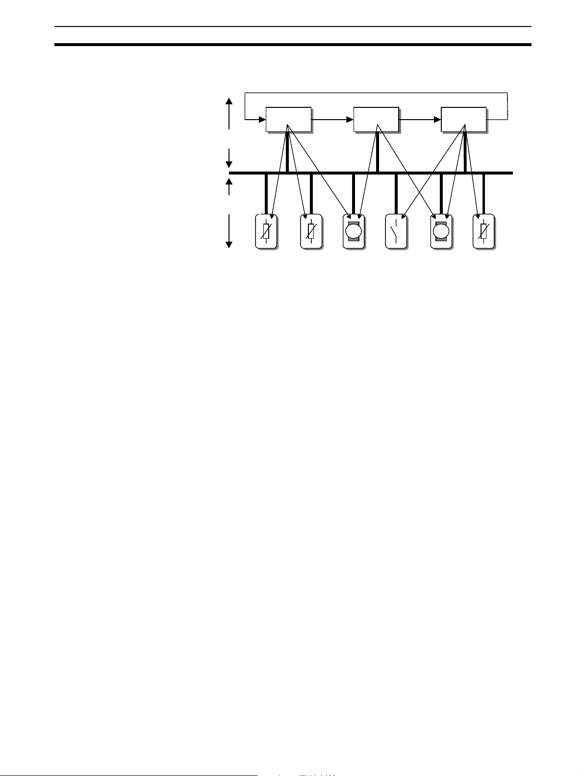
Polling procedure The po lling or m aster-slave proce dure perm its the m aster, currently in pos-
session of the token, to access its assigned slaves. The figure below shows a
possible configuration The configuration shows three active stations (masters) and six passive stations (slaves).
4
Page 19
Overview of PROFIBUS
Section 1-1
To ke n P a ssin g
DPM1 DPM2 DPM1
Active statio n s
Master devices
Polling
PROFIBUS
Passive stations
Slave devices
The three masters form a logical token ring. When an active station receives
the token message, it can perform its master role for a certain period of time.
During this time it can communicate with all assigned slave stations in a master-slave communication relationship, and a DPM 2 master can take th e i nitiative to communicate with DPM1 master stations in a master-master
communication relationship.
Multi-peer communication In addition to logical peer-to-peer data transmission, PROFIBUS-DP provides
multi-peer communication (broadcast and multicast).
Broadcast communication In the case of broadcast communication a master station sends an unac-
knowledged message to all other stations (masters and slaves).
Multicast communication In the case of multicast comm unication a master station s ends an unacknow-
ledged message to a predetermined group of stations (masters and slaves).
1-1-5 Diagnostic functions
Extensive Diagnostics Extensive diagnostic functions defined in PROFIBUS-DP enable the fast loca-
tion of error at slave devices. Diagnostic messages are transmitted over the
bus and collected at the master. Three levels of diagnostic messages are
defined:
Device Related
Diagnostics
Module Related
Diagnostics
Channel Related
Diagnostics
• Messag es conc erning the general operat ional s tatus of the whole device,
e.g. over temperature, low voltage.
• Messages indicating that an error is present in a specific I/O range of a
station, e.g. an 8-bit output module.
• Messages indicating an error at a given input or output, e.g. short circuit
on Output 5.
5
Page 20

Overview of PROFIBUS
Section 1-1
1-1-6 Protection Mechanisms
Monitoring Time PROFIBUS-DP provides effective protection functions against parameteriza-
tion errors or failure of the transmission equipment. Time monitoring is provided both at the master and the slave devices. The monitoring interval is
specified when the system is configured.
Monitoring at the Master The PROFIBUS-DP Master monitors data transmission of the slaves with the
Data-Control-Timer. A separate control timer is used for each slave. This
timer expires if response data is not correctly transmitted by the slave within
the monitoring inter val. The user is informed when this happens. If the automatic error reaction (Auto-CLEAR) has been enabled, the PROFIBUS-DP
master exits its OPERATE state, switches the outputs of all assigned slaves
to the fail-safe status and changes to the CLEAR state.
Monitoring at the Slave Slave devices use a watchdog to detect failures of the master or the bus. If
data communication with the master does not occur wi thin the set watchdog
time interval, a slave automatically switches its outputs to the fail-safe mode.
Also, access protection is provided for the inputs and outputs of the slaves
operating in multi-master systems. Only authorized masters can access their
slaves.
1-1-7 Network States
PROFIBUS-DP distinguishes four different network states:
OFF-LINE • Communi cation with al l PROFIBUS-DP participants (masters and slaves)
is stopped. The Master ceases to access the PROFIBUS network.
STOP • Communica tion bet ween the master and its slaves is stopped. O nly com -
munication between the master and other masters is still possible.
CLEAR • The ma ster tries to s et parameters, check the configuration, and perform
data exchange with its associated slaves. Data exchange involves reading the inputs of the PROFIBUS-DP slaves and writing zeros to the outputs of the slaves.
OPERATE • The master exchanges data with its as signe d s laves, inputs are read a nd
outputs are written. Also, the master cyclically sends its local status to all
its assigned PROFIBUS-DP slaves (using a broadcast message).
Auto-CLEAR
Fail-safe State
If an error occurs during the data exchange phase of the master, the ‘AutoCLEAR’ function determines the subsequent actions. If this function has been
disabled, the master remains in the OPERATE state. If the function has been
enabled, the master automat ically changes the network to the CLEAR state,
in which the outputs of the assigned P ROFIBUS-DP slaves are switched to
zero, i.e. the ‘fail-safe’ state. The master continues to read the inputs of the
slaves.
6
Page 21

Setting up a PROFIBUS-DP Network
Section 1-2
1-2 Setting up a PROFIBUS-DP Network
1-2- 1 Configuring the PROFIBUS-DP Master
In order to operate a PROFIBUS network, each m aster in the ne twork needs
to be configured. This process of PROFIBUS master configuration involves
• setting up the network topology, i.e. assigning the slave stations with
which the master will be exchanging data,
• def ining the para meter iz atio n dat a, w hich t he m ast er w ill se nd to each of
the slave devices, before process data exchange can commence
• defining the c onfiguration data, i.e. defining the process data, which will
be exchanged,
• setting up the bus parameters, which define the baud rate and the bus
timing parameters.
• downloading the configuration setup to the master device.
Configuration technology The configuration process is usually facilitated by a special Com puter based
program, often referred to as a Configurator. The Configurator requires special configuration files, defining the configuration options for each device,
which is to participate in data exchange. The files must be provided by the
manufacturer of the device.
Two types of configuration technology exist:
• Configuration technology based on FDT/DTM technology
• Configuration technology based on GSD-files
1-2-2 FDT/DTM Technology
FDT/DTM technology The newer configuration tools are based on FDT/DTM technology.
FDT/DTM Concept The FDT/DTM concept specifies the interfaces between the enginee ring sys-
tems called Field Device Tools (FDT), and the device-specific software components called Device Type Managers (DTM).
The FDT/DTM concept separates the device dependent functionality (which is
in the DTM) from the application. It opens up interfaces for device configuration, monitoring and maintenanc e solutions, which before were largely manufacturer-specific interfaces. Because of this concept, FDT/DTM technology is
not limited to PROFIBUS applications. In concept, any type of network can be
configured and accessed, provided the appropriate DTMs are available.
FDT Container application A FDT container application facilitates configuration of network devices and
parameterizing and/or manipulating their operational modes. All device
dependent functionality is concentrated in the DTM.
FDT container applications can be stand-alone tools, or can be part of other
engineering tools such web browsers providing FDT interfaces.Since FDT
standardizes the interfaces, it allows devices from different manufacturers to
be integrated in any automation system, regardless of the fieldbus system.
CX-Profibus is an example of a FDT container appl ication. It is described in
detail in the following sections.
Device DTM DTMs are provided by the manufac turer of the device. A DTM is comparable
to a printer driver, which allows interactive configuration and diagnostics.
The DTM provides not only the configuration, manipulation and monitoring
functions for a device including the User interface functions, it also provides
the connection technology to the device.
7
Page 22

Setting up a PROFIBUS-DP Network
DTM properties In general, a DTM is a Microsoft COM-component, which can be executed
from within a FDT container application. A DTM is not a stand-alone tool, it
requires a FDT container application to be executed. The DTM provides a
number of interface functions, through which it can be controlled and
accessed in order to tr ansfer data to or from the DTM.
A DTM provides all the options for configuration and monitoring of a device,
which it can present to the user through its own user interface.
ActiveX User interface The User Interface for a DTM is provided using ActiveX windows. Control of
these windows is done by the DTM, but the FDT containe r application can
request specific user input f rom the DT M, based on which the DTM will provide the necessary ActiveX windows. In general multi-language user interface
windows, including DTM specific Help files are supported by the DTM.
XML based data transfer Data transfer to and from a DTM is provided using XML-documents. The
XML-documents are standardized for the communication between the FDT
container application and for communication between DTMs.
An additional specification covers the definition of X ML-data formats for the
transfer of application specific data, such as PROFIBUS data.
Communication DTM In general, a device configuration DTM is accompanied by a communication
DTM. This specific DTM facilitates device specific communication, e.g. for
downloading a configuration to a PROFIBUS-DP Master Unit and/or for
retrieving monitoring information from PROFIBUS-DP Master Unit. It may
incorporate the specific communication protocol, or rely on other available
drivers.
Section 1-2
CX-Profibus CX-Profibus is a FDT container application. Together with this container appli-
cation, OMRON provides two DTMs:
• A DTM to facilitate configuration of the CS1W-PRM21/CJ1W-PRM21
PROFIBUS Master Units
• A DTM to facilitate integration of GSD file based devices in to CX-Profibus
(see section
1-2-3 GSD file Technology
for more information)
1-2-3 GSD file Technology
GSD file technol ogy The older and most com mon ly us ed co nfiguration tech nology is the bas ed on
GSD files (Gerätestammdaten file). A GSD file is a text file, containing the
characteristic features and configuration options of a device. The device data
base file of each device is loaded in the configurato r and downloaded to the
master device.
GSD files are usually sup plied with e ach unit. Alter natively, GSD files can be
downloaded from the Inter net , either f rom the manufacturer's site, or from the
GSD library of the PROFIBUS Nutzer Organisation at http://www.profibus.com.
GSD file language The language used in the GS D file is indicated by the last letter of the file
extension, *.GS?:
Default = GSD
English = GSE
German = GSG
Itali a n = GSI
Portuguese = GSP
Spanish = GSS
8
Page 23

PROFIBUS-DP Master Unit
The GSD files are prepared individually by the vendor for each type of device,
according to a fixed format. Some parameters are mandatory, some have a
default value and some are optional. The device data base file is divide d into
three parts:
General section • General specifications
This section contains the vendor name, the device name, hardware- and software release versions, station type and identification number, protocol specification and supported baud rates.
DP-master section • DP master-related specifications
This section contains all parameters which onl y apply to DP master devices
(e.g. maximum memory size for the master parameter set, maximum number
of entries in the li st of active stations, or the maximum number of slaves the
master can handle).
DP-slave section • DP slave-related specifications
This section contains all specification related to slaves (e.g. minimum time
between two slave poll cycles, specification of the inputs and outputs, and
consistency of the I/O data).
DTM versus GSD file When comparing the two configuration technologies, a GSD file only provides
information on the device characteristics and conf iguration options. It has no
GUI of its own, nor can it connect to the device itself. A GSD file always
requires a separate configu rator program to interpret t he data. In the FDT/
DTM concept all these device related functions are included in the DTM. The
DTM can be executed from any program, which provides FDT interfaces.
Section 1-3
1-3 PROFIBUS-DP Master Unit
1-3-1 PROFIBUS-DP Master Unit Features
PROFIBUS-DP Master Unit The PROFIBUS-DP Master Unit is a CPU Bus Unit, which can be installed on
a CS1/CJ1 PLC System. Th ere are two available models of the PROFIBUSDP Master unit: the CS1W-PRM21 for connection to a CS1 PLC System and
the CJ1W-PRM21 for connection to a CJ1 PLC System . Both mode ls provide
identical functionality.
CPU Bus Unit A total of up to 16 CPU Bus Units can be mounted on t he CPU Rack or an
Expansion Rack. The total of 16 must include all PROFIBUS-DP Master units
and all other CPU Bus Units
Unit Control and status Up to 25 words of control and status words are exchanged between the
PROFIBUS-DP Master Unit and a dedicated CI O memor y area, of whi ch the
location is related to the Unit Number. Control bits, allow the PLC program to
switch the Unit between OFF-LINE, STOP, CLEAR and OPERATE mode,
which represent the main PROFIBUS-DP modes of operation. The control
words also allow for user initiated transmission of a Global_Con trol messa ge
over the PROFIBUS network to any group of Slave stations.
The remaining CIO words provide status and di agnostics information on the
Unit itself, the PROFIBUS network and the Slave stations allocated to the
PROFIBUS-DP Master unit.
I/O dat a The total size of I/O data however, must not exceed the maximum I/O size of
up to 7168 words, whic h i t ca n exchange wi th th e PLC memor y. The I/O data
9
Page 24

PROFIBUS-DP Master Unit
can be distributed over up to two input areas and 2 output areas. Each of the
input and output areas can be mapped to any location in the DM Area, CIO
Area, WR Area, HR Area, or the EM banks.
FINS messages The PROFIBUS-DP Master Uni t suppor ts FINS message exchange with the
PLC CPU to allow the transfer of Slave diagnostics data, or the Error log.
Also, the user can enable or disable communication with specific allocated
slave stations, so that they can temporarily be taken out of the network for
maintenance, without the PROFIBUS-DP Master Unit reporting an error.
PROFIBUS-DP functions The PROFIBUS-DP Master Unit suppor ts all mandatory ser vices defined in
the PROFIBUS-DP standard EN50170, Volume 2 for Master - Slave Communication. These functions includes the following services:
• Set_Prm
• Chk_Cfg
• Slave_Diag
• Data_Exchange
• Global_Contr o l (FREEZE, UNFREEZE, SYNC, UNSYNC , C LE AR)
The PROFIBUS-DP Master Unit suppor ts cyclic Master - Slave communications for networks with up to 125 Slave stations. With each Slave station it can
exchange up to 244 bytes of input data and up to 244 bytes of output data.
For diagnostics purposes t he PROFIBUS-DP Master Unit collects all Slave
Diagnostics messages, which i t ca n be transferred to the P LC memory, using
FINS commands. From every allocated Slave station it can receive up to 244
bytes of diagnostics data.
Section 1-3
Configuration Before t he P ROFIBUS-DP Ma ster Unit can control the PROFIBUS networ k, it
must be configured, using the dedicated configuration program CX-Profibus.
Without this configuration, the Unit will not be able to achieve data exc hange.
Troubleshooting
Functions
The Configurator is explained in section
The PROFIBUS-DP Master Unit is provided with a variety of troubleshooting
functions for prompt recovery in case of errors:
• Extensive self-diagnostic function at start up
• Data exchange flags, indicating if I/O data is being exchanged with the
slave stations
• Diagnos tics flags, indicating if new Slave diagnostics data is available
• Extensive status and error flags, indicating the status of the Unit and the
PROFIBUS network
• Error log for recording error history data
1-4 CX-Profibus Configurator
1-3-2 Specifications
PROFIBUS-DP Master Unit Model
Applicable PLC Unit classi fication Ty pes of communications Model number
CS Series CPU Bus Unit • Remote I/O communications mast er CS1W-P RM21
CJ Series CJ1W-PRM21
General Specifications General specifications of the CS/CJ-series P ROFIBUS-DP Master Units con-
form to the general specificati o n s for the SYSMAC CS/CJ-series CPU Units.
10
Page 25
PROFIBUS-DP Master Unit
Functional Specifications
Item Specification
PROFIBUS-DP Master Unit types CS1W-PRM21 CJ1W-PRM21
Applicable PLC seri es CS-series CJ-series
Mounting position • CPU Rack,
Unit classification CPU Bus Unit
Applicabl e unit numbers 0 to F (Hex )
Maximum number of Units that can be
mounted per PLC
Current consumpt ion 400 mA max at 5 Vdc
PLC types
Ambient temperat ure Operating: 0 to 55°C
Humidity 10% to 90% (with no condensati on)
Dimensions (W x H x D) 35 x 130 x 101 mm 31 x 90 x 65 mm
Weight 187g (typical) 100g (typical)
Conformance to EMC and environmental
standards
Environment
Settings Unit Number rotary swit ch, range: 0 ~ F (Hex)
Indicators 7 LEDs, indicating Unit status and PROFIBUS status:
PROFIBUS Connector 9-pin sub-D female connector (#4/40 UNC thread)
Front case
CIO Area words allocated for the CPU Bus
Unit
DM Area words allocated for the CPU Bus
Unit.
I/O Data allocations Maximum total size: 7168 words
Memory area allocation
Section 1-3
•CPU Rack,
• CS Expansion Rack (Not including a C200H Expansio n
I/O Rack or SYSMAC BUS
Slave Rack.)
•CS1D Duplex
16
Storage: –20 to 75°C
EN 61000-6-2:2001
EN61131-2:1994+a12:2000
Unit status: RUN (Green LED)
ERC (Red LED)
Host PLC status: ERH (Red LED)
Configuration st atus: PRM (Green LED)
PROFIBUS status: BST (Green LED)
COMM (Green LED)
BF (Red LED)
Fixed all ocation of 25 words per Unit.
CIO 1500 + (25 x Unit number)
CIO words provide:
• 2 words f or software switches
• 1 word for the Global_Control
• 21 words f or the Unit and Slave stat uses
Fixed all ocation of 100 words per Unit.
DM 30000 + (100 x Unit number)
DM Area allocated to the Unit is reserv ed for future use.
I/O Data words can be allocated to up to 2 input areas and 2 output
areas
Input areas and output areas can be mapped to
•CIO Areas
• DM Areas
• WR Areas
• HR Areas
• EM banks
Mapping must be defined through Configurator
• CJ1 Expansion Rack
11
Page 26

PROFIBUS-DP Master Unit
Item Specification
Reading Slav e station diagnostics The MEMOR Y AREA READ (0101) FINS command can be used to
Reading and controlling the error log The internal error log records the history of error events. The Unit
Station state changes Allocated Slave stations can be disabled and enabled in order to
FINS messaging
Error history siz e and stor age The PROFIBUS Master unit supports st orage of up to 80 error
Error lo g
Protocol Specification
Item Specification
Applicabl e standards EN50170, Vol um e 2
Protocol type suppor ted PROFIBUS-DP
PROFIBUS Unit types PROFIBUS-DP Class 1 Master
PROFIBUS Media type RS-485, galvanically i solated from the PLC
PROFIBUS Connector 9-pin sub-D female connector (#4/40 UNC thread)
Unit station address range
Number of slave stations supported
baud rates supported Selectable through Configurator:
Bus timing definitions Calculated by Configurator
PROFIBUS interface
Master Class 1 - Slave cyclic services • Set_Prm
Master Class 1 - Slave acyclic services Not supported
Master Class 1 - Slave services
availabl e t o the PLC
Master - Master services Not supported
PROFIBUS-DP Services
Section 1-3
obtain the last received Slave Diagnostics message.
supports the follo w ing Error Log related FINS commands:
• ERROR LOG READ
• ERROR LOG CLEAR
temporarily rem ov e t hem from dat a e xchan ge servi ces. The int ernal
error log records the history of error ev ents. The Unit supports the
following FINS commands to implement this:
•RUN
•STOP
events, including time stamps in vol atile memory.
16 error events can be logged in non-volatile memory
Termination to be provided by the cable connector according to
EN50170
0 ~ 125, set through Configurator
125 max, address range
• 9.6 kbi t/s
• 19.2 kbit/s
• 45.45 kbit/s
• 93.75 kbit/s
• 187 kbit/s
• 500 kbit/s
• 1.5 Mbit/s
•3 Mbit/s
•6 Mbit/s
• 12 Mbit/s
• Chk_Cfg
• Data_Exchange
• Slave_Diag
• Global_Control - CLEAR
Global_Control, initiated from CIO Word:
Can be addressed to all slave stations or a specified group of
slaves stations
Supported commands:
• SYNC
• UNSYNC
• FREEZE
• UNFREEZE
0 ~ 125
12
Page 27
PROFIBUS-DP Master Unit
RUN
ERC
BST
BF
ISOM
CS
F
E
D
C
B
A
9
8
7
6
5
4
3
2
1
0
RUN
ERC
BST
BF
ERH
PRM
COMM
Item Specification
Number of I/O module definitions 4000 max. ove r al l configured Slave stations
Number of I/O data supported by Master Up to 244 bytes input and 244 bytes output max. per Slave station
Number of diagnostics data supported by
Master
I/O Data
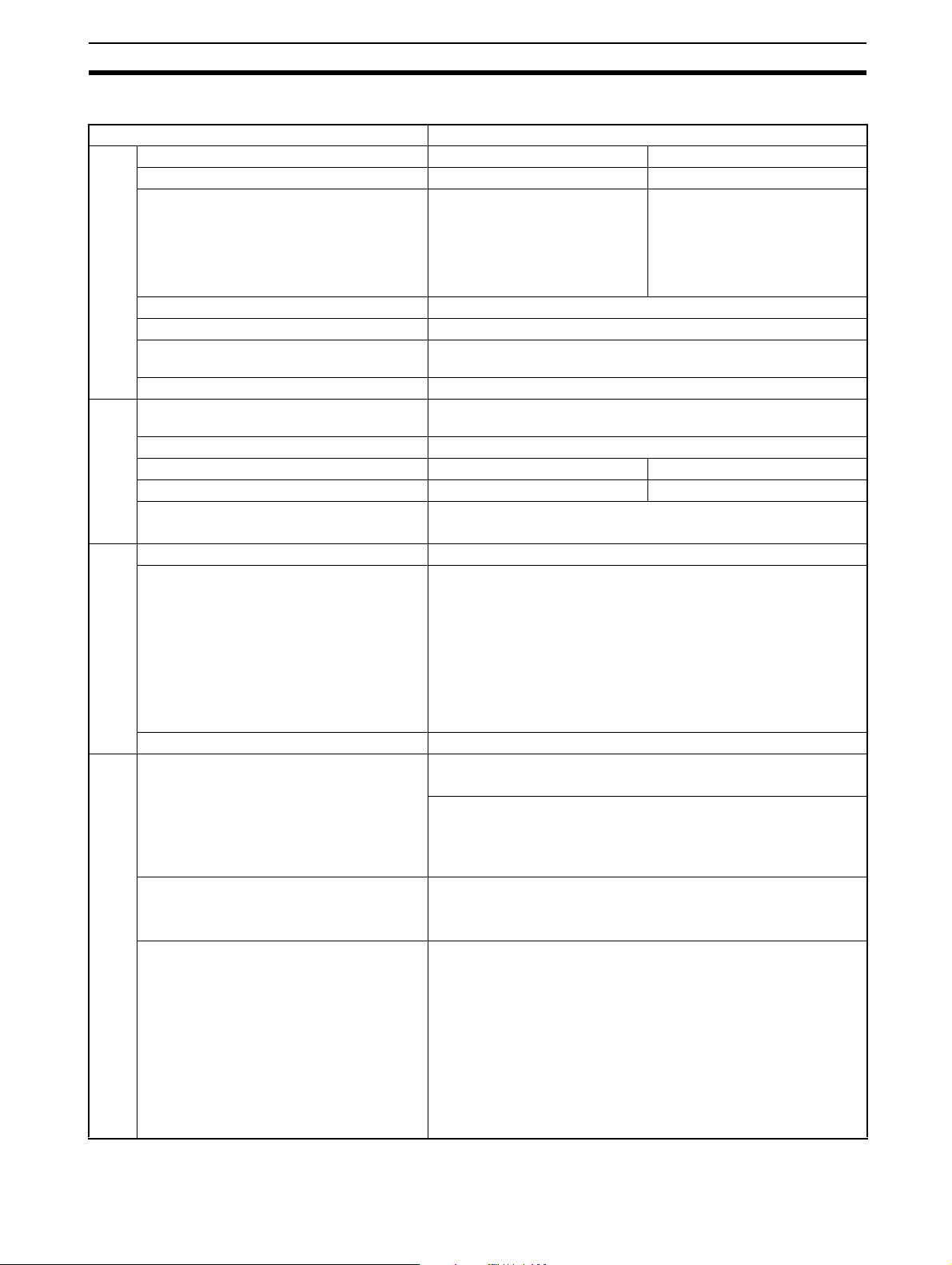
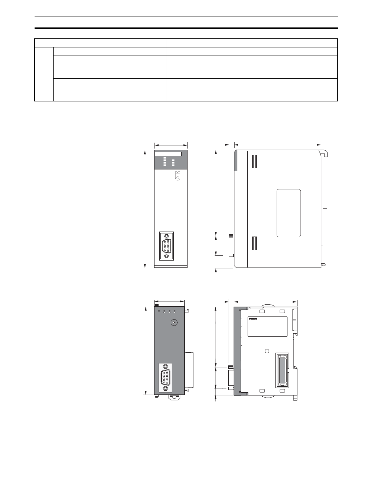
External Dimensions
(defined by Slave station)
Total sum of all I/O Data must not exceed 7168 words
Up to 244 bytes of diagnostics max. per Slave station
Diagnostic data is collected at the Unit, and can be obtained from
the Unit using FINS messaging
CS1W-PRM21
35
Section 1-3
3
101
PRM21
RUN
ERC
BST
BF
UNIT
No.
ERH
PRM
COMM
CS
RUN
ERC
ISOM
BST
BF
94
130
BUS
25
11
(UNIT: mm)
CJ1W-PRM21
PRM21
RUN
31
ERC
COMM
PRM
BST
BF
ERH
UNIT
5
4
6
3
7
2
8
1
9
0
A
NO.
F
B
E
C
D
3
65
54
90
BUS
25
11
(UNIT: mm)
13
Page 28

PROFIBUS-DP Master Unit
1-3-3 Comparison with Previous Model
The following table provides a comparison between the CS1W-PRM21/
CJ1W-PRM21 PROFIBUS-DP Master Units and their predecessor, the
C200HW-PRM21 PROFIBUS-DP Master used in a CS-series PLC
Item C200HW-PRM21 CS1W-PRM21/CJ1W-PRM21
Unit classificati on C200H Special I/O Unit CPU Bus Unit
Mounting position • CPU Rack,
• C200H I/O Expansion Rack,
• CS-series Expan sion Rack
• Can not be mounted on a CS1D PLC
Applicable Unit numbers 0 to F (Hex) 0 to F (Hex)
Maximum number of Units
per PLC
Allocated CIO Area words 2,000 to 2,004 + (10 x unit number)
Allocated DM Area words D20000 to D20017 + (100 x unit number)
I/O Data allocatio ns Maximum total si ze: 300 words per Unit
16 16
Up to 4 CIO words contain:
• Command settings
• Unit Status and err or flags
• Error reporting f rom the PROFIBUS inter-
face
The area contains user defined memory
mapping of I/O data
At start up this area is transferred to the Unit
I/O Da ta words can be allo cate d to up to 2
input areas and 2 output areas
I/O size per are a: up to 200 words
Mapping / area siz e set i n DM words:
• CIO: CIO 0000 to CIO 0235
• CIO: CIO 0300 to CIO 0511
• CIO: CIO 1000 to CIO 1063
• HR: HR000 to HR099
• DM: D00000 to D05999
• CPU Rack,
• CS/CJ-series Expansion Rack
• CS1W -PRM21 can be mounted on CS1D
1,500 to 1,524 + (25 x unit number)
Up to 25 CIO words contain:
• Command settings
• Unit Status and error flags
• PROFIBUS st atus and error flags
• Slave status flags
D30000 to D30099 + (100 x unit n umber)
Not used on the Unit. Reserve d for future
use
Maximum tota l si ze: 7168 words per Unit
I/O Data words can be al located to up to 2
input areas and 2 out put areas
I/O size per area: up to 7168 words
Mapping and area size set by Configurator:
• CIO: CIO 0000 to CIO 6143
• WR: W000 to W511
• HR: HR000 to HR511
• DM: D00000 to D32767
• EM: E00000 to E32767 (Banks 0 to C)
Section 1-3
Default mapping (DM words contain 0000 ):
• Output area: CIO 0050 to CIO 0099
• Input area: CIO 0350 to CIO 0399
• Diagnostic fl ags: CIO 0200 to CIO 0215
Message communications Message communicati on using IOWR and
IORD PLC instructions:
• IOWR to send Global-Control command
• IORD to read slave diagnostics
FINS message communication not supported
Configuration connection
method
PROFIBUS Media type RS-485, galvanically isolated from the PLC RS-485, galvanically isolated from the PLC
Serial connection (RS232) directly to connector on the front of the Unit
Default mapping: Not supported
Note Diagnostics flags: available in allo-
cated CIO Area words
FINS message communi cation. Commands
supported:
• MEMORY AREA READ to read Slave station diagnost ics message
• ERROR LOG READ, to read the Unit’ s
error log
• ERROR LOG CLEAR to clear the Unit’s
error log
• RUN to enable communicati on wit h a
slave station
• STO P to di sable communication with a
slave station
Serial connection directly via PLC CPU, or
via other I/O Units .
No separate connector on the front of the
Unit
14
Page 29

PROFIBUS-DP Master Unit
Item C200HW-PRM21 CS1W-PRM21/CJ1W-PRM21
PROFIBUS Connector 9-pin sub- D female connector (#4/40 UNC
thread)
Termination provided through a switch on
the unit according t o EN50170
Unit station address range
Number of Slave stations
supported on the network
baud rates supported Selectable through Confi gurator:
Bus timing definit ions Calculated by Configurator Calculated b y Configurator
Master Class 1 - Sla v e cyc lic
services
Master Class 1 - Sla ve acyclic services
Master Class 1 - Slave services available to the PLC
Master - Master services Not supported Not supported
Error reporting Error numbers are transferred to CIO word
0 ~ 125, set through Configurator 0 ~ 125, set through Configurator
125 max, address range
• 9.6 kbit/s
• 19.2 kbit/s
• 93.75 kbit/s
• 187 kbit/s
• 500 kbit/s
• 1.5 Mbit/s
• 3 Mbit/s
• 6 Mbit/s
• 12 Mbit/s
• Set_Prm
•Chk_Cfg
• Data_Exchange
• Slave_Diag
• Global_Control - CLEAR
• Get_Cfg
• Set_Slave_Addr
• Rd_In
•Rd-Out
Global_Contro l, initiated from CIO Word:
Can be addressed to one or all slave sta-
tions or a specified group of slaves stations
Supported commands:
• SYNC
• UNSYNC
• FREEZE
• UNFREEZE
• CLEAR
Internal logging not supported
0 ~ 125 125 max, address range 0 ~ 125
9-pin sub-D femal e connector (#4/40 UNC
thread)
Termination must be provided by the cable
connector according to EN50170
Selectable through Configurator:
• 9.6 kbit/s
• 19.2 kbit /s
• 45.45 kbit/s
• 93.75 kbit/s
• 187 kbit/s
• 500 kbit/s
• 1.5 Mbit/s
•3 Mbit/s
•6 Mbit/s
•12 Mbit/s
•Set_Prm
• Chk_Cfg
• Data_Exchange
•Slave_Diag
• Global_Control - CLEAR
Not supported
Global_Contr ol, initiated from CIO Word :
Can be addressed to all slave stations or a
specified group of slaves stations
Supported commands:
• SYNC
• UNSYNC
• FREEZE
• UNFREEZE
80 error events can be logged in volatile
memory.
16 error e v ents can be logged i n non-v o lati le
memory
Errors can be retrieved through FINS messages
Section 1-3
15
Page 30

CX-Profibus Configurator
Section 1-4
1-4 CX-Profibus Configurator
1-4-1 CX-Profibus Fe atu r es
CX-Profibus The PROFIBUS-DP Master Unit requires a configuration before it can
exchange I/O data with the Slave stations. For this purpose OMRON provides
the CX-Profibus Configuration program, which runs under Microsoft Windows™ NT 4.0, Windows™ 2000 or Windows™ XP
Together with the CX-Profibus Container applicat ion, OMRON provides two
DTM COM Objects:
• A DTM to configure the CS1W-PRM21 / CJ1W-PRM21
• A DTM to allow the handling of classic GSD files in CX-Profibus
The following presents a quick overview of the functions.
CX-Profibus FDT
Container application
CS1W-PRM21/CJ1-PRM21
DTM
CX-Profibus provides an FDT environment in which DTMs can be executed.
The main function of CX-Profibus is to facilitate the DTMs and the data
exchange between them. It provides:
• Network setup functions: A tree view shows the relations between the
DTMs, i.e. the relation between the Master and Slave devices.
• Device Catalogue functions: A Device Catalogue con taining the installed
DTMs is maintained, to which the user can add new DTMs or delete
them. Device DTMs can be added to the network from this Catalogue.
• Project maintenance func tions: CX-Profibus provides the functions to create, save and open project files. It also facilitates user access control,
allowing the limitation of use to authorized personnel only, using password protection.
• Additional func tions: CX-Profibus provides additional functions like printing, error logging, FDT Communication logging and help files.
The CS1W-PRM21/CJ1W-PRM21 DTM consists of three parts:
• The Setting s DTM, which handles the configuration for the PROFIBUSDP Master Unit. This includes the bus parameters settings, the I/O data
mappings and Master specific settings. The Settings DTM provides its
own User Interface.
• The Monitoring DTM, which handles the status monitoring and control
over the PROFIBUS-DP Master unit, when it is on-line and communicating over the PROFIBUS network. It provides its own User interface to
read out Master status flags and Error log, as well as Slave status flags
and the Slave diagnostics messages received by the Unit. It also allows
the user to send Global_Control messages over the network and to
change the PROFIBUS-DP Master Unit’s mode on the PROFIBUS network.
• The com munication DTM, which provides the interface between the t wo
DTMs mentioned above and CX-Server. Cox-Server, which is provided
with the CX-Profibus packages is the driver providing communication
between the PC and the PLC CPU.
Generic Slave DTM The Generic Slave DTM allows the handling of classic GSD files of up to GSD
revision 3 within CX-Profibus. Upon allocating a Slave station, for which only
a GSD file is available to a Master Unit in the network, this DTM will be
invoked. This DTM also consists of two parts:
• The Settings D TM will provide the user interface to display the device’s
information and the selectable values, as defined in the GSD. After making the neces sary confi guration settin gs, these will be trans ferred to t he
Master DTM automatically.
16
Page 31

CX-Profibus Configurator
r
Section 1-4
• The monitoring DTM will provide a diagnostics interface to the user,
allowing him to check the Slave’ s status. This DTM obtains the necessary
information from the PROFIBUS-DP Master Unit’s monitoring DTM.
Downloading th e
configuration
After setting up the configuration, it must be downloaded to the PROFIBUSDP Master Unit. The type of serial connection to use for downloading,
depends on the Unit:
• CS1W-PRM21/CJ1W-PRM21: Connection to the Unit is achieved
through the serial port of the PLC CPU, using CX-Server. Cox-Server
also allows routing the download through multiple systems, if supported
by these systems. The CS1W-PRM21/CJ1W-PRM21 Units do not support message routing.
Serial connection to CS/CJ-series
PROFIBUS-DP Master Unit
Cx-Profibus
Configurato
CS/CJ-series
PROFIBUS-DP
Master Unit
COM Port on PC
Peripheral Bus or
Host LINK
OMRON
SYSMAC CS1G
PROGRAMMABLE
CONTROLLER
Peripheral or RS232C
Port of CPU Unit
PROFIBUS Network
17
Page 32

CX-Profibus Configurator
1-4-2 Specifications
Function a l specificati ons
Item Specification
Model number WS02-9094G
Hardware platform • Personal computer: IBM PC/AT or compatible
Operating System • MS Windows NT4.0
Connection to CS1W-PRM21/CJ1WPRM21
Connection to C200HW -PRM21 • RS-232C port of PC with Configuration port on the Unit.
Operating environment
General Proje ct functions File handling: CX-Pr ofibus supports ov erall handling of project files
Network setup functions CX-Profibus provides network tree view, from which hierarchy
Device Catalogue functions The Device Catalogue maintains the installed device DTMs. After
Support functions CX-Profibus provides the following additional support functions:
CX-Profibus
Section 1-4
• Processor: Pentium 500 MHz or hi gher
• Memory: 256 Mbytes
• Hard disk: A minimum of 256 Mbytes
• CD-ROM drive
• Graphics resolution: 800 x 600 pixels minimum
• Serial port: RS-232C; COM1 to COM4 supported
• MS Windows 2000
• MS WindowsXP
• Peripheral or RS-232C port of PC with PLC CPU. Serial communications mode: Peripheral bus, Host Link, Toolbus, supported by
CX-Server.
• Communication cable: Cable CS1W-CN226 to connect to the
peripheral port on the CPU (Not included in package).
as well as network data.
• New: Start a new project.
• Open: Open an existing project fi le.
• Save (As): Save a project file.
• Export: Export project data to HTML.
• Properties: Edit project property information.
User management: Functionality of CX-Profibus can be limited as
defined by several password protected access levels. CX-Profibus
supports separate password definitions and login for:
• Administrator
• Planning engineer
• Maintenance engineer
• Operator
• Observer
between Master and Slave stations can clearly be distinguished.
The following network functions are avail able:
• Network DTMs (i.e. devices) can be add ed or del eted, using drag
and drop from the Devi ce Catalogue.
• Network DTMs can be copied and mo ved from one location to
another in the network view.
• DTM names can be edited by the user.
• Any change to the par ameters of a DTM is clearly marked in the
tree view, until the project is sav ed.
installati on of a new DTM, the user can refresh the data base. The
Device Catal ogue provides the following functions:
• Update Device Catalogue.
• Add device DTMs to the network directly.
• Install a GSD file. This function allows co pying of GSD files to a
specific direct ory, after which they ar e available for the Generic
Slave DTM.
• Context sensitive help function.s.
• Error logging.
• Monitoring of FDT communication between DTMs.
18
Page 33

CX-Profibus Configurator
Item Specification
Device set up Device se tup allows the user to:
Master setup This functi on allows the user to define the Unit’s behavior in case of
Bus parameter setup The bus parameter setup allows the selection of baud rate and cal-
Slave area setup The Slave area setup allows the user to define the I/O Data map-
Monitoring func ti ons • Master status read-out.
Support functions • Context sensitive help functions.
CS1W-PRM21 / CJ1W-PRM21 DTM
General funct ions The Generic Slave DTM reads the contents of a specific GSD file
I/O Configurati on setup The I/O Configuration setup fu nction allows:
Par am eter setup The Para me ter setup function:
Group setting The Group setup function allows defini tio n of the group to which the
Monitoring functions The Monitoring functions provides a display of
Support functions • Context sensitive help functions.
Generic Slav e DTM
Section 1-4
• Set the Unit number related to the actual PROFIBUS-DP Master
unit.
• Configure the com munication link between the PC and the Unit.
This function invokes the User Interface of CX-Server.
• Test the Units communication link and to read out the Unit’s information.
• a network malfunction.
• a PLC mode change between PROGRAM mode and MONITOR/
RUN mode.
It also allows the definition of Auto- addressing, which simp li fies I/O
data mapping.
culation and edi ti ng of specific bus par am eters.
ping of the I/O Data from each of the Sla ve stations on to the PLC
memory areas. This can be done automatical ly, but also allows editing by the user.
• Slave status and slave diagnostics read-out.
• Read-out of the Unit’s error log.
located in a special sub-directory, and displays the setup options to
the user. It supports
• GSD file revisions 1 and 2 (PROFIBUS-DP f unctionality).
• GSD file revi sions 3 (PROFIBUS-DPV1 funct ionality).
• Selection of Station address.
• Enable/disable watchdog.
• Overview of availabl e I/ O modules.
• Selection of I/O modules, including Addition, Insertion and
Removal of mult ip le mo du l es .
• Setting of common as well as module dependent parameters.
• Setting of PROFIBUS-DP Extension parame ters.
associated Slave station will belong.
• Standard Slave diagnostics flags.
• Extended diagnostics messages.
• Multi-language support.
19
Page 34

Basic Operating Procedure
1-5 Basic Operating Procedure
1-5-1 Overview
The following diagram provides an overview of the installation procedures.
For experienced installation engineers, this may provide sufficient information. For others, cross-references are made to various sections of this manual
where more explicit information is given. When reading this manual online, the
flow chart entries provide links to the sections containing detailed information.
Section 1-5
(1)
(2)
(3)
Mount the PROFIBUS-DP Master Unit
on to the PLC.
Select a unique Identity number (0 - F)
for the Unit with the rotary switch on the
front of the Unit.
Connect the PROFIBUS-DP Master Unit
to the PROFIBUS network.
Switch on the power supply for the PLC
(4)
and create a PLC I/O table in
CX-Programmer. See CX-Programmer
User Manual (Reference No. W361).
Configure the PROFIBUS-DP Master
(5)
Unit using Cx-Profibus on the PC.
(6)
Download configuration data to
PROFIBUS-DP Master Unit.
20
PROFIBUS-DP starts communicating,
confirmed by the COMM LED
continuously lit. Check status of other
LEDs. (Section 2 refers.)
Page 35

Basic Operating Procedure
1-5-2 Preparations for Communications
Section 1-5
1,2,3...
1. Mount the Master Unit on the PLC system (refer to
PROFIBUS-DP Master Unit
• Treat the Unit as a CPU Bus Unit.
• It can be mounted to a CPU Rack or Expansion Rack.
• Number of Units: 16 (Max).
2. Set the Unit No. (UNIT No. ) for the PROFIBUS-DP Master Unit (refer to
3-1 Selecting a unit number
3. Connect a PC or a Programming Device to the PLC and turn ON the power
supply to the PLC.
4. Generate the I/O tables and restart the PLC (refer to
table
).
5. Install CX-Profibus, and the DTMs on to the PC.
).
).
1-5-3 Procedures Prior to Starting Communications
Use the following procedure to configure the Unit using CX-Profibus:
1,2,3...
1. Wire the network, to connec t the PROFIBUS-DP Master un it to the slave
stations.
2. Turn ON the PLC power supply and the power supplies of the Slave station
on the network.
3. In CX-Profibus, create a network and define the parameters and I/O configurations for the PROFIBUS-DP Master Unit settings and the allocated
Slave stations. Determine the baud rate and the bus parameter setup.
Make sure that the “Go to OPERA TE mode“ option is selected, to force the
Unit to OPERATE mode upon a PLC mode change t o RUN / MONITOR
mode.
4. Download the network configuration to the PROFIBUS-DP Master Unit. After downloading the configuration, CX-Profibus will restart the PROFIBUSDP Master Unit.
5. After restarting t he PROFIBUS-DP Master Unit it will automatically start
communication.
2-2 Installing the
2-
2-3-2 Creating an I/O
21
Page 36

Basic Operating Procedure
Section 1-5
22
Page 37

SECTION 2
Installation and Wiring
This sect ion sho w s the P R OFI BUS de vic e and identi f ies its c ontrols and i ndi cators . It contai ns the pro cedure s for i nsta lling
the PROFIBUS-DP Master unit on the PLC System a nd setting up the PROFIBUS network.
2-1 Unit Components . . . . . . . . . . . . . . . . . . . . . . . . . . . . . . . . . . . . . . . . . . . . . . 24
2-1-1 Nomenclature . . . . . . . . . . . . . . . . . . . . . . . . . . . . . . . . . . . . . . . . . . 24
2-1-2 Indicators . . . . . . . . . . . . . . . . . . . . . . . . . . . . . . . . . . . . . . . . . . . . . 25
2-1-3 Switch Settings . . . . . . . . . . . . . . . . . . . . . . . . . . . . . . . . . . . . . . . . . 26
2-1-4 PROFIBUS Connector . . . . . . . . . . . . . . . . . . . . . . . . . . . . . . . . . . . 27
2-2 Installing the PROFIBUS-DP Master Unit . . . . . . . . . . . . . . . . . . . . . . . . . . . 28
2-2-1 Handling Precautions . . . . . . . . . . . . . . . . . . . . . . . . . . . . . . . . . . . . 28
2-2-2 Mounting the CS1W-PRM21 . . . . . . . . . . . . . . . . . . . . . . . . . . . . . . 28
2-2-3 Mounting the CJ1W-PRM21 . . . . . . . . . . . . . . . . . . . . . . . . . . . . . . 30
2-3 Initial Setup Procedure . . . . . . . . . . . . . . . . . . . . . . . . . . . . . . . . . . . . . . . . . . 31
2-3-1 Selecting a unit number . . . . . . . . . . . . . . . . . . . . . . . . . . . . . . . . . . 32
2-3-2 Creating an I/O table. . . . . . . . . . . . . . . . . . . . . . . . . . . . . . . . . . . . . 32
2-4 Setting up a Network. . . . . . . . . . . . . . . . . . . . . . . . . . . . . . . . . . . . . . . . . . . . 33
2-4-1 Network Structure. . . . . . . . . . . . . . . . . . . . . . . . . . . . . . . . . . . . . . . 33
2-4-2 Bus Termination . . . . . . . . . . . . . . . . . . . . . . . . . . . . . . . . . . . . . . . . 36
2-4-3 PROFI BUS Cable Connector . . . . . . . . . . . . . . . . . . . . . . . . . . . . . . 36
2-4-4 Shielding Precautions . . . . . . . . . . . . . . . . . . . . . . . . . . . . . . . . . . . . 37
2-5 Defining PROFIBUS-DP in the Software. . . . . . . . . . . . . . . . . . . . . . . . . . . . 37
23
Page 38

Unit Components
CS
F
E
D
C
B
A
9
8
7
6
5
4
3
2
1
0
RUN
ERC
BST
BF
ERH
PRM
COMM
2-1 Unit Components
2-1-1 Nomenclature
The illustration below shows the Status LED indicators, the Unit number
selector switch, and a 9-pin female sub-D connector on the front side of the
CS1W-PRM21 and the CJ1W-PRM21 Units. Each of these compo nents are
explained in the following sections
CS1W-PRM21
Section 2-1
PRM21
RUN
ERC
BST
BF
UNIT
No.
ERH
PRM
COMM
CS
Indicators
Unit number switch
This switch sets the Unit Number of the
PROFIBUS-DP Master Unit as a one-digit
hexadecimal number
PROFIBUS-DP Connector
BUS
9-Pin Sub-D, female connector, #4/40 UNC thread
Connect the PROFIBUS-DP network cable to this
connector. Termination must be provided with the
cable connector
CJ1W-PRM21
PRM21
RUN
ERC
COMM
PRM
BST
BF
ERH
UNIT
4
5
3
6
2
7
1
8
0
9
F
NO.
A
E
B
D
C
Indicators
Unit number switch
This switch sets the Unit Number of the
PROFIBUS-DP Master Unit as a one-digit
hexadecimal number
BUS
PROFIBUS-DP Connector
9-Pin Sub-D, female connector, #4/40 UNC thread
Connect the PROFIBUS-DP network cable to this
connector. Termination must be provided with the
cable connector
24
Page 39

Unit Components
CS
RUN
ERC
BST
BF
ERH
PRM
COMM
2-1-2 Indicators
The PROFIBUS-DP Master Units are each f itted with seven LEDs to indicate
the operational mode and status of the Unit and the PROFIBUS network
CJ1W-PRM21CS1W-PRM21
PRM21
RUN
ERC
COMM
PRM21
RUN
ERC
BST
BF
ERH
PRM
COMM
CS
Indicator specifications
Indicator Color Status Meaning
RUN Green Not lit • Startup test failed, Unit not operat ional.
• Operation stopped, due to a fatal error.
Lit Initialization successful, Unit i s in normal operation.
ERC
(PROFIBUS-DP Master
Unit Error)
ERH
(PLC Error)
PRM
(Param eter database)
BST
(Bus status)
COMM
(I/O Data communicat ion)
BF
(Bus Fail)
Red Not lit Unit is in normal operation.
Lit One of the following errors occurred:
• Startup error.
• Non-vol ati le memory error (checksum failed, write-v erify failed).
• Invalid PROFIBUS parameter configuration set ting.
• Fatal error in program execution.
Red Not lit PLC CPU in normal operation.
Lit One of the following errors occurred:
• PLC CPU Bus error.
• Cyclic Refresh Monitor Time-out.
Green Not lit PROFIBUS Parameter configuration is not availabl e or i ncorrect.
Flashing PROFIBUS P aramet er con figur at ion i s bei ng tr ansf er red to the Uni t and
is not yet available.
Lit PROFIBUS Pa rameter configuration is correct, and operational.
Green Not lit The PROFIBUS-DP Master Unit is in OFFLINE or ST OP mode.
Flashing The PROFIBUS-DP Master Unit is in CLEAR mode.
Lit The PROFIBUS-DP Master Unit is in OPERATE mode.
Green Not lit No PROFIBUS data excha nge wit h any of the allocated slaves.
Flash in g Fatal error oc c u rr ed (E RC LED is ON) . U n it in it ia liz a tion failed.
Lit PROFIBUS data exchange ongoing with at least one all ocated slave.
Red Not lit No PROFIBUS commun ication errors occurred.
Flashing At least one allocated slave is not in data exchange with the Unit.
Lit An error occurred in the PROFIBUS interface of the Unit
(see section
7-2 Troubleshooting Using LED Indicators
ERH
PRM
BST
BF
Section 2-1
).
Note Unless otherwise specified, the frequency of a flashing LED is 1 Hz (50% duty
cycle).
25
Page 40

Unit Components
F
E
D
C
B
A
9
8
7
6
5
4
3
2
1
0
Section 2-1
2-1-3 Switch Settings
Setting the Unit Number The unit number is used to identify individual CPU Bus Units when more than
one CPU Bus Unit is mounted to the same PLC. The unit number must be
unique for each CPU Bus Unit. Selecting a non-unique number for a CPU Bus
Unit will prevent the PLC System from starting correctly.
Note Always turn OFF the power to the PLC CPU before changing the Unit number
Note If the unit number is being set for the first time or changed, then an I/O table
Unit Number and CPU Bus
Unit Word Allocations
CS1W-PRM21
CJ1W-PRM21
Setting range:
0 ~ F (Hexadecimal)
UNIT
UNIT
5
4
6
3
No.
1. Turn OF F the power supply before setting the Unit number.
2. Set the switch to the new Unit number. Use a small screwdriver to make
the setting, taking care not to dama ge the rotary switch. Th e un it number
is fact o ry-set to 0.
3. Turn ON the power again.
setting. The Unit only reads the Unit number setting dur ing the initialization
following a power-up, but not follo wing a software reset.
must be created for the PLC.
With CS/CJ-series PLCs, words are automatically allocated in th e CIO Area
and the DM Area. The PROFIBUS-DP Master Unit uses these words for
receiving control data from the CPU Un it and for notifying the CPU Unit of
PROFIBUS-DP Master Unit and communications status. The word addresses
in the allocated areas for the CPU Bus Unit are impor tant when creating the
user program for using the PROFIBUS-DP M ast er Un it. This must be considered when setting the unit number.
The CIO and DM Word al locations are discuss ed in detail in
CIO Area Words
ber and the allocated CIO Area and DM Area words.
. The tables below show the relation between the unit num-
7
2
8
1
9
0
A
NO.
F
B
E
C
D
4-2 Allocated
Unit No.
(decimal)
0 (0) CIO1500 to CIO15 24 8 (8) CIO1700 to CIO1724
1 (1) CIO1525 to CIO15 49 9 (9) CIO1725 to CIO1749
2 (2) CIO1550 to CIO1574 A (10) CIO1750 to CIO1774
3 (3) CIO1575 to CIO1599 B (11) CIO1775 to CIO1799
4 (4) CI O1600 to CIO1624 C (12) CI O1800 to CIO1824
5 (5) CI O1625 to CIO1649 D (13) CI O1825 to CIO1849
6 (6) CIO1650 to CIO1674 E (14) CIO1850 to CIO1874
7 (7) CIO1675 to CIO1699 F (15) CIO1875 to CIO1899
26
Allocated wor ds Unit No.
(decimal)
Allocated words
Page 41

Unit Components
DM Area Allocations
Unit No.
(decimal)
0 (0) D30000 to D30099 8 (8) D30800 to D30899
1 (1) D30100 to D30199 9 (9) D30900 to D30999
2 (2) D30200 to D30299 A (10) D31000 to D31099
3 (3) D30300 to D30399 B (11) D31100 to D31199
4 (4) D30400 to D30499 C (12) D31200 to D31299
5 (5) D30500 to D30599 D (13) D31300 to D31399
6 (6) D30600 to D30699 E (14) D31400 to D31499
7 (7) D30700 to D30799 F (15) D31500 to D31599
2-1-4 PROFIBUS C onne ct or
The PROFIBUS connector on the font of the Unit is a 9-pin female sub-D connector, as recommended by the PROFIBUS standard EN 50170.
Pin No. Signal Description
9
6
5
1
1 Shield Shield/protective ground
2-3 RxD/TxD-P Receive/Transmit data - plus (B wire)
4 RTS Control signal for repeaters (direction control) (TTL)
5 DGND Data ground (reference potential for VP)
6 VP Supply voltage of the terminator re sistance (5 Vdc)
7-8 RxD/TxD-N Receive/Transmit data - min us (A wire)
9--
Allocated words Unit No.
(decimal)
Section 2-1
Allocated words
The signal RTS (TTL signal) is for the direction control of repeat ers, which do
not have a self-controlling capability.
The signals DGND and V P are used to power the bus ter minator located in
the cable connector.
Note The orientation of the sub-D connector allows the use of PROFIBUS connec-
tors with a 90° angle cable outlet, e.g ERNI, Delconec and Phoenix.
Note The 9-pin sub-D connector uses #4/40 UNC thread, for mechanical fixation of
the cable connector. Make sure that if non-standard PROFIBUS connectors
are used, the corresponding thread is used on the cable connector.
27
Page 42

Installing the PROFIBUS-DP Master Unit
pply
2-2 Installing the PROFIBUS-DP Master Unit
2-2-1 Handling Precautions
When installing the PROFIBUS-DP Master Unit on the PLC system, observe
the following handling precautions
• Always turn OFF the power supply to the P LC before mounting or dismounting a Unit or connecting or disconnecting cables.
• Provide separate condui ts or ducts for the I/O lines to prevent noise from
high-tension lines or power lines.
• Leave the label on top o f the Unit attached when wirin g. Removing the
label prior to wiring may result in malfunction if foreign matter enters the
Unit.
• Remove the label after the completion of wiring to ensure proper heat dissipation. Leaving the label attached may result in malfunction.
2-2-2 Mounting the CS1W-PRM21
The CS1W-PRM21 PROFIBUS-DP Master Unit can be mounted to any slot in
either a CS-series CPU Rack, a CS-series Expansion CPU Rack or a CS1
Duplex CPU Rack. The CS-series PLC supports up to 7 Expansion CPU
Racks, in addition to the CPU rack.
The number of slots to whi ch PROFIBUS-DP Master Uni t can be mo unted
depends on the Backplane. Up to 16 PROFIBUS-DP Master Units can be
mounted to a single PLC system. If it is mounted in com bination with other
CPU Bus Units (e.g., Ethernet Units), the maximum total num ber of CP U Bus
Units that can be mounted is 16.
.
CS1W-BC023 / BC033 / BC053 / BC083 / BC103 CPU Backplane
CS-series CPU Rack
Can mount to any position,
with 2, 3, 5, 8, or 10 slots.
CPU
PS
Section 2-2
28
2, 3, 5, 8, or 10 slots
(Expansion Backplane not possible with 2-slot CPU Backplane.)
CS1W-BI033 / BI053 / BI083 / BI103 CS-series Expansion Backplane
CS-series Expansion Rack
Can mount to any position,
PS
with 3, 5, 8, or 10 slots.
3, 5, 8, or 10 slots
C200H Expansion I/O Backplane
C200H Expansion Rack
PROFIBUS-DP Master Unit cannot be
PS
mounted to any slots.
CPU: CPU Unit
PS: Power Su
Note The CS1W-PRM21 PROFIBUS-DP Master Unit’s maximum current consump-
tion is 400 mA. M ake sure that the total current consumption of all the Units
connected to the same CPU Backplane or Expansion Backplane does not
exceed the output capacity of the Power Supply Unit.
Up to 16 Units can be mounted
to the slots shown in the diagrams
on the left.
Unit
Page 43

Installing the PROFIBUS-DP Master Unit
Section 2-2
Mounting Procedure Mo unt the CS 1W-PRM21 PROFIBUS-DP Master Unit to the Backplane usi ng
the following procedure.
!Caution Always turn OFF the power supply to the PC before mounting or di smou nting
a Unit or connecting or disconnecting cables.
1,2,3...
1. Hook the claw on the top of the Unit onto the Backplane.
Claw
Backplane
2. Insert the Unit i nto Backplane co nnectors and sec urely tighten th e screw
at the bottom of the Unit. Tighten the screws to a torque of 0.4 N•m.
3. When removing the Unit, first loosen the screw at the bottom of the Unit.
Fixing screws
Note When mounting the Unit, provide the clearance shown below to facilitate easy
mounting or dismounting.
Duct
Duct
Philips screwdriver
20 mm min.
Backplane
20 mm min.
29
Page 44

Installing the PROFIBUS-DP Master Unit
/O
ace Unit
2-2-3 Mounting the CJ1W-PRM21
The PROFIBUS-DP Master Unit can be mounted to any slot in either a CJseries CPU Rack, or a CJ-series Expansion CPU Rack. The CJ-ser ies PLC
supports up to 4 Expansion CPU Racks, in addition to the CPU rack.
The number of slots to which PROFIBUS-DP Master Unit can be mounted i n
any of the positions shown be low using the sliders on the top a nd bottom of
the Unit. Up to 16 PROFIBUS-DP M aster Units can be mounted t o a single
PC. If it is mounted in combination with o ther CPU Bus Units (e.g., Ethernet
Units), the maximum total number of CPU Bus Units that can be mounted is
16.
Section 2-2
PLC CPU rack
P
SIC
Expansion Backplane
PSI
Expansion Backplane
PSI
Expansion Backplane
10 Units max.
C
P
U
10 Units max.
I
10 Units max.
I
10 Units max.
End cover
End cover
Up to 16 PROFIBUS-DP M
Units can be mounted.
End cover
End cover
30
PSI
I
PS: Power Supply Unit
CPU: CPU Unit
IC: I/O Control Unit
Interf
II: I
Note The CJ1W-PRM21 PROFIBUS-DP Master Unit’s maximum current consump-
tion is 400 mA. M ake sure that the total current consumption of all the Units
connected to the same CPU Backplane or Expansion Backplane does not
exceed the output capacity of the Power Supply Unit.
Page 45

Initial Setup Procedure
Section 2-3
Mounting Procedure Mount the CJ1W-PRM21 PROFIBUS-DP Master Unit to the PLC using the fol-
lowing procedure.
1. Carefully align the connectors to mount the PROFIBUS-DP Master Unit.
Connector
P
A205R
PO
W
E
R
L1
A
C
1
0
0
-2
4
0
V
IN
P
U
T
L2/N
R
U
N
O
U
T
P
U
T
A
C
2
4
0
V
D
C
2
4
V
2. Move the yellow sliders on the top and bottom of the Unit un til they click
into position, to lock.
SYSMAC
CJ1G-CPU44
P
R
O
G
R
A
M
M
A
C
O
N
T
R
O
LLE
R
B
L
E
O
P
E
N
M
C
P
W
R
B
U
S
Y
PERIPHERAL
PORT
R
U
N
E
R
R
/A
L
M
IN
H
P
R
P
H
L
C
O
M
M
PRM21
R
U
N
E
R
C
PRM
C
O
M
M
E
R
H
B
S
T
B
F
U
N
IT
5
4
6
3
7
2
8
1
9
N
O
.
0
A
F
B
E
C
D
BUS
PA205R
POWER
L
1
A
C
1
0
0
-2
4
0
V
IN
P
U
T
L
2
/N
R
U
N
O
U
T
P
U
T
A
C
2
4
0
V
D
C
2
4
V
Note If the sliders are not securely locked, the PROFIBUS-DP Master Unit func-
tions may not operate correctly.
To dismount the Unit, move the sliders to the “Release” direction.
2-3 Initial Setup Procedure
After mounting the PROFIBUS-DP Mast er unit to its PLC System, the following Initial Setup Procedure must be applied to allow the Unit to start up properly and to be configured for operation.
• A unique unit number must be selected, before the PLC’s power supply is
turned on.
• An I/O t able must be created in t he PLC, in order to registe r the Unit on
the PLC CPU.
SYSMAC
CJ1G-CPU44
P
R
O
G
R
A
M
M
A
C
O
N
T
R
O
L
L
E
Slider
PR
M
R
U
N
E
R
R
/
A
L
M
I
N
H
B
L
E
P
R
P
H
L
R
C
O
M
M
O
P
E
N
M
C
P
W
R
B
U
S
Y
PERIPHE
RAL
P
O
R
T
21
R
U
N
ERC
P
R
M
C
O
M
M
ERH
BST
B
F
U
N
IT
5
4
6
3
7
2
8
1
9
N
O
.
0
A
F
B
E
C
D
B
U
S
Release
Lock
BUS
31
Page 46

Initial Setup Procedure
2-3-1 Selecting a unit number
1. Make sure that the PLC Po wer Supply is turned OFF before setting the Unit
number.
2. Set the switch to the desired unit number. Use a small screwdriver to make
the setting, taking care not to dama ge the rotary switch. Th e un it number
is factory-set to 0. Make sure that the unit num ber is uni que on the PLC,
i.e. there must be no other CPU Bus Units with the same unit number.
3. Turn ON the PLC Power Supply.
After setting the unit number, the PLC CP U must now register the PROFIBUS-DP Master Unit, by creating an I/O table.
2-3-2 Creating an I/O ta ble
An I/O table is used to identify Units connected to the PLC and to allocate I/O
to them. The I/O table is stored with the PLC CPU, and loaded at start up. If
any change is made to the Unit c onfiguration of a CS/CJ-series PC, the I/O
table must be created again to register the Units to the CPU Unit.
Section 2-3
Connecting a
Programming Device
Applicable Prog ram m i ng
Devices
Connecting P rogram m ing
Devices
Procedure for Creating an
I/O Table
To create the I/O table, connect a Programming Device (such as a Programming Console or Cx-Programmer) to the PLC.
The following Programming Devices can be used with CS/CJ-series PLCs.
Programming Console
Model number Key Sheet (required) Recommended cable (required)
C200H-PRO27-E CS1W-KS001-E CS1W-CN224 (cable length: 2.0 m)
CS1W-CN624 (cable length: 6.0 m)
CX-Programmer and CX-Net
Model number: WS02-CXP @@-EV2
The operations are explained here using a P rogramming Con sole. For details
regarding the Cx-Programmer and the C x-Net, refer to the
User’s Manual
Cx-Net is software that comes with Cx-Programmer and is automatically
installed when Cx-Programmer is installed.
To connect a Programming Co nsole, attach a CS/CJ-series Key Sheet and
then connect the Console to the CPU Unit’s peripheral port. (It cannot be connected to the RS-232C port.)
The procedure for creating an I/O t able is shown h ere, taking as an example
an I/O table that is generated automatically for a PLC connected online. In this
example, a Programming Console is used for creating the I /O table. For an
explanation of how to create an I/O table using a Cx-Programmer, refer to the
Cx-Programmer User’s Manual
Use the following procedure to create the I/O table.
.
.
Cx-Programmer
32
Page 47

Setting up a Network
Initial screen
000000 I/O TBL ?
CHG
000000 I/O TBL
WRIT ????
000000CPU BU ST?
0:CLR 1:KEEP
SHIFT
Password
CH
*DM
Section 2-4
WRITE
or
000000 I/O TBL
WRIT OK
(Save or clear the CPU Bus Unit System Setup.)
After creating the I/O table, the Unit is ready to be configured for first use on
the PROFIBUS-DP network.
Note After mounting the Unit and starting it up for the first time, the Unit’s Configu-
ration is empty. This will cause the red ERC LED on the front of the Unit to be
switched ON. In this situation, the Unit can still be configured.
2-4 Setting up a Network
2-4-1 Network Structure
Communication medium The PROFIBUS standard defines the use of EIA RS-485 as the main commu-
nication transport medium. The PROFIBUS-DP Master Unit is designed to
interface directly to this type of medium. T his s ection wi ll discuss the s etup of
networks based on this medium.
Note The other communication medium specified for PROFIBUS is optical fibre.
The PROFIBUS-DP Master U nits does not provide a direct interface to this
type of medium. However, by using third party coup lers an interface between
EIA RS-485 and optical fibre networks can be made.
Linear Bus Topology PROFIBUS-DP defines the use of the Linear Bus Networ k Topology. T he B us
must be terminated at both ends, and must not contain network branches.
The total cable length of the bus depends on the cable and the selected baud
rate. Also, RS-485 specifies a maximum of up to 32 stations - master and
slave stations - per line segment. If more than 32 stations are to be connected, or if the total length of the segment must be extended beyond its maximum, repeaters must be used to link the separate segments.
33
Page 48

Setting up a Network
Section 2-4
Note Repeaters are devices which connect two segme nts. They do not have a sta-
tion address of their own, but they do count in the total number of stations in a
segment.
Repeaters A maximum of up to three repeaters between two stations in a network can be
used, i.e. a network can consist of up to 4 segments. The maximum number
of PROFIBUS stations in such a network is then 122. The figure below shows
an example of a two-segment network.
OMRON
SYSMAC CS1G
PROGRAMMABLE
CONTROLLER
Termination
Station 1
Termination
Termination
Repeater
Station 2 Station 3 Station 31
Station 63 Station 33 Station 32
Termination
Tree Topology The use of repeat ers allows the extension of three or more Linear Bus seg-
ments in to a Tree topology. In a tree topology more than three repeaters are
allowed, provided that there are no more than three repeaters between any
two stations in the network. The following figure presents an example of a network with more than three segments and repeaters.
Segment 1
Max. 31 stations
M / S
Segment 2
Max. 31 stations
M / S
34
R
Segment 4
Max. 31 stations
M / S
M / S
Master or slave station
R
Repeater
Termination
Max. total num ber of stations = 126
R
Segment 3
Max. 28 stations
Segment 5
Max. 30 stations
R
R
M / S
R
Segment 6
Max. 31 stations
M / S
M / S
Page 49

Setting up a Network
Section 2-4
Cable Type The PROFIBUS standard EN 50170 specifies Type A shielded, twisted- pair
cable as the recommended cable type for use in an RS-485 bas ed PROFIBUS network. This cable type has the following characteristics:
Characteristic Value
Impedance 135 - 165 ohms
Capacitance per unit length < 30 pF/m
Loop resistance 110 ohms/km
Core diameter 0.64 mm
Cor e c ross sec t ion
0.34 mm
2
Note The PROFIBUS standard EN 50170 also specifies a Type B cable with slightly
different cable characteristics. This Type B cable is no longer recommended
for us e .
Maximum PROFIBUS
Cable Length
The transmission speed defines the maximum advised cable distance or
cable segment in metres before the use of a repeater is recommended. The
cable lengths specified in the following table are based on PROFIBUS type A
cable.
Baud rate
(kbit/s)
9.6 1200 500 400
19.2 1200 1500 200
45.45 1200 3000 100
93.75 1200 6000 100
187.5 1000 12000 100
Distance/segment
(m)
Baud rate
(kbit/s)
Distance/segment
(m)
Note If the network must be extended beyond the range of the advised cable
length, the use of a fibre optic segment to cross the larger distance shoul d be
considered.
Stub Lines Passive Stub lines (branches from the main line) should be avoided for data
transmission speeds of more than 500 kbit/s. Except at end stations with termination, it is recommended to always use plug connec tors that permit two
data cables to be connected directly to the plug. This method allows the bus
connector to be plugged and unplugged at all times without interrupting dat a
communication between other stations.
35
Page 50

Setting up a Network
k
A
k
Section 2-4
2-4-2 Bus Termination
Termination resistors In order to minimize cable reflections and ensure a defined signa l level on the
VP
390 Ohm
B-Line
220 Ohm
A-Line
390 Ohm
DGND
Networ
Inductors In addition to the bus termination, additional precautions must be taken to
B-Line
-Line
110 mH
Networ
110 mH
data lines, the data transfer cable must be terminated at both ends with a terminating resistor combination. The bus termination diagram is shown on the
left.
The bus terminator connects the two data lines via a 220 ohm resistor which,
in turn, is connected to VP 5Vdc and DGND via two 390 ohm resistors. Powering the terminator resistor via VP 5V and DGND ensures a defined idle
state potential on the data lines.
To ensure the c orrect functioning up to the highest baud rate, the bus cable
must be terminated at both its ends.
A missing bus term ination can cause errors during data t ransfer. Problems
can also arise if too many bus terminators are fitted, since each bus terminator represents an electr ical load and reduces the signal levels and thus the
signal-to-noise ratio. Too many or missing bus terminators can also cause
intermittent data transfer errors, particularly if the bus segment i s operated
close to the specified limits for maximum numbers of stations, maximum bus
segment length and maximum data transfer rate.
ensure proper operation at high baud rates, i.e. baud rates of 500 kbit/s and
higher. Due to the capacitive load of the station and the resulting cable reflections, bus connectors must be provided with built-in seri es inductors, of 110
mH each, as shown in the figure on the left.
Installing the inductors applies to all stations on t he network, and not only to
the stations at both ends of the bus cable.
2-4-3 PROFIBUS Cable Connector
Bus Cable Connector The plug connector to be used on the CS/CJ-series PROFIBUS-DP Master
Unit is a 9-pin male sub-D type, preferably encased in metal and h aving a
facility to connect the shield of the cable to the c ase or to pin 1. The cable
should be connected to the receive / transmit lines, pin 3 (B-line) and pin 8 (Aline).
The use of special PROFIBUS-DP cable connectors, which are available from
several manufacturers, is highly recommended. Various models are widely
available, with or without the bus term ination and inductors built-in. If provided
in the connector, the Bus termination can often be enabled or disabled
through a switch on the connector.
The special PROFIBUS-DP cable connectors often provide a convenient way
of connecting the cables. The figure on the left, pro vides an example of such a
bus cable connector.
A standard 9-pin sub-D p lug can only be used if the P ROFIBUS-DP Master
Unit is not at the start or the end of a bus segment, or on a stub line at a baud
To next
station
From
previous
station
rate of 500 kbit/s or less.
The two PROFIBUS data lines are designated A and B. There are no regulations on which cable core color should be connected to which of the two data
terminals on each PROFIBUS device; the sole requirement is to ensure that
the same core color is connected to the same terminal (A or B) for all stations
throughout the entire system (across all stations and bus segments). The
36
Page 51

Defining PROFIBUS-DP in the Software
PROFIBUS Organization recommends the following rule for data line color
codes: PROFIBUS cables in general will use the colors red and green for the
data lines, with the following assignment:
Data cable wire A - green
Data cable wire B - red
This rule applies to both the incoming and the outgoing data lines.
Section 2-5
2-4-4 Shielding Precautions
Cable shield connection To ensure electro-magnetic compatibility (EMC), the shield of the cable should
be connected to the metal case of the plug connector.
Inside cabinet
Ground Rail
If the Unit is installed in a control cabinet, the bus cable shield should be
brought into physical contact with a grounding rail using a grounding clamp or
similar device. The cable shield should continue in the cabinet ri ght up to the
PROFIBUS device.
Ensure that the PLC an d the control cabinet in which it is mounted have the
same ground potential by providing a large-area metall ic contact to ground,
e.g. galvanized steel to ensure a goo d electrical connection. Grou nding rails
should not be attached to painted surfaces.
For further information regarding PROFIBUS network installation, please refer
to “Installation Guideline for PROFIBUS-DP/FMS” (PNO Order No. 2.112),
which is available at every regional PROFIBUS Organization. The information
covers:
Outside cabinet
• Commissioning of PROFIBUS equipment.
• Tes ting the PROFIBUS cable and bus connectors.
• Deter mi ning loop resistance.
• Tes ting for correct bus termination.
• Deter mi ning the segment length and cable route.
• Other test methods.
• Example of an equipment re port in the PROFIBUS guideline.
2-5 Defining PROFIBUS-DP in the Software
Defining the Configuration After making the physical co nnections of the n etwork, the c onfiguration then
has to be defined in th e software. OMRON provides a dedicated PC-based
configuration program, called CX-Profibus, as well as the required DTMs for
this purpose. It must be used to:
• Define the master(s).
• Assign slaves to their respective master(s).
• Assign slaves to groups for broadcast/multicast messages.
• Enter bus parameters, e.g. baud rate, target rotation time etc.
Downloading th e
Configuration
The system must be downloaded to the master Unit after configuring it at the
PC. This is made possible by either connecting the serial COM port of the PC
to the CS1/CJ1 PLC with a serial interface cable, or use an ethernet connection between the PC and the CS1/CJ1 PLC via an ethernet unit.
37
Page 52

Defining PROFIBUS-DP in the Software
Section 2-5
38
Page 53

SECTION 3
Configuration Soft ware
This section contains the procedures for installing the configuration software. It also presents an overview of the
Configuration software and di scusses the main aspects of defining a PROFIB US configuration .
3-1 Installation. . . . . . . . . . . . . . . . . . . . . . . . . . . . . . . . . . . . . . . . . . . . . . . . . . . . 40
3-1-1 Installation Requirements . . . . . . . . . . . . . . . . . . . . . . . . . . . . . . . . . 40
3-1-2 Installation Procedure . . . . . . . . . . . . . . . . . . . . . . . . . . . . . . . . . . . . 40
3-2 CX-Profibus . . . . . . . . . . . . . . . . . . . . . . . . . . . . . . . . . . . . . . . . . . . . . . . . . . 47
3-2-1 Starting CX-Profibus . . . . . . . . . . . . . . . . . . . . . . . . . . . . . . . . . . . . 47
3-2-2 CX-Profibus Main Window . . . . . . . . . . . . . . . . . . . . . . . . . . . . . . . 48
3-2-3 Device Catalogue . . . . . . . . . . . . . . . . . . . . . . . . . . . . . . . . . . . . . . . 51
3-2-4 Updating the Device Catalogue . . . . . . . . . . . . . . . . . . . . . . . . . . . . 53
3-2-5 Saving and Opening Projects . . . . . . . . . . . . . . . . . . . . . . . . . . . . . . 53
3-2-6 Adding Devices to the Network . . . . . . . . . . . . . . . . . . . . . . . . . . . . 54
3-2-7 Exporting to HTML . . . . . . . . . . . . . . . . . . . . . . . . . . . . . . . . . . . . . 55
3-2-8 Error Logging and FDT Monitoring. . . . . . . . . . . . . . . . . . . . . . . . . 56
3-2-9 Access Control and User Management. . . . . . . . . . . . . . . . . . . . . . . 57
3-3 PROFIBUS-DP Master DTM . . . . . . . . . . . . . . . . . . . . . . . . . . . . . . . . . . . . . 60
3-3-1 Configuration User Interface . . . . . . . . . . . . . . . . . . . . . . . . . . . . . . 60
3-3-2 Diagnostics User Interface . . . . . . . . . . . . . . . . . . . . . . . . . . . . . . . . 68
3-3-3 Connecting to the PROFIBUS-DP Master Unit . . . . . . . . . . . . . . . . 74
3-4 Generic Slave Device DTM . . . . . . . . . . . . . . . . . . . . . . . . . . . . . . . . . . . . . . 77
3-4-1 Configuration User Interface . . . . . . . . . . . . . . . . . . . . . . . . . . . . . . 77
3-4-2 Diagnostics User Interface . . . . . . . . . . . . . . . . . . . . . . . . . . . . . . . . 80
39
Page 54

Installation
3-1 Installation
3-1-1 Installation Requi rements
CX-Profibus Configuration software is required to configure the PROFIBUSDP Master before operating the network. Without a valid configuration the
PROFIBUS-DP Master Unit will not be able to achi eve dat a communi cation
with the slave stations on the network.
The following are the minimum requirements for a PC to install the CX-Profibus Configurator software:
• PC Pentium III or higher, 500 MHz minimum
• Operating System: Win dows 2000/NT/XP
• RAM: 256 MB minimum
• Hard disk space: 256 MB minimum
• Graphics resolution: 800 x 600 pixels minimum
• Serial port: RS-232C; COM1 to COM4 supported
• CD ROM drive
• Mouse for drag and drop operations.
• Communica tion cable: Cable CS1W-CN226 to connect to the peripheral
Section 3-1
port on the CPU (Not included with CX-Profibus)
3-1-2 Installation Procedure
This section explains how to install the CX-Profibus configuration software for
the PROFIBUS-DP Master Unit. CX-Profibus and its c omponents are installed
by executing the setup program of the Configurator.
CX-Profibus CD-ROM CX-Profibus is provided on a CD-ROM, w hich contains the following compo-
nents:
• Microsoft.NET Framework
• CX-Profibus FDT Container application.
• CS1W-PRM21/CJ1W-PRM21 Configuration DTM.
• CX-Server, to allow communication between the PC and the PLC
• Generic Slave Device DTM, to allow slave configuration using GSD files.
• Additional GSD files for several OMRON slave stations.
Note 1. Provided with the CD-ROM is a 16-digit installation key, which can be
found on a label attached to the CD-ROM box. The key is unique to the
CD-ROM and is required to allow full installation of the software. The key
is also used as reference when registering the purchased software with
OMRON.
2. If during installation the 16-digit License code was not en tered, the program will run in demo mode, i.e. it provides all functionality , but for a limited
period of 30 days. After this period has expired, the License code must be
provided to the program, to allow continuation of use.
3. During the limited perio d of 30 days, the valid License code, as shown on
the CD-ROM case can be entered at anytime when the program is running,
by selecting the License button in the Help - About CX-Profibus from the
main menu.
4. Administrator rights are required to install CX-Profibus.
40
Page 55

Installation
Section 3-1
5. The operations and displays shown in the following procedure may differ
slightly depending on the version of Windows software being used. The
displays for Windows 2000 are shown here.
1,2,3...
1. Exit all other Windows-based programs.
2. Insert the setup disk (CD-ROM) into the CD-ROM drive.
3. Double-click
The setup program for CX-Profibus will start. A progress dialog window is displayed, indicating progress of the setup as the program is loaded.
4. During the preparation, th e InstallShield wizard will determine if the Microsoft.NET framework needs to be installed. This package is required
during installation and for ex ecuting CX-Profibus. If already present on the
PC, the installation will be skipped, and the installation proc ess will proceed with step 7. Installation of the Microsoft.NET framework first displays
the Licence window, as shown below.
Setup.exe
.
In order for the installation to continue, the user must agree to the License
statement and click the Install button
41
Page 56

Installation
Section 3-1
5. After starting the Microsoft.NET framework installation process, a window
will be displayed showing the progress of this installation.
6. Completion of the Microsoft.NET framework installation is indicated by displaying the message window below.
7. After installing the Microsoft.NET framework, CX-Profibus and its components will be installed. The installation welcome window as shown below
will be displayed. Click the Next button to continue.
8. After the welcome w indow the window conta ining the License statement
for CX-Profibus is displayed. The License window is shown below. Please
read the License carefully , bef ore selecting the Yes button to accept the Li-
42
Page 57

Installation
Section 3-1
cense. If the License is not accepted - by selecting the No button -, th e installation will be terminated.
9. After accepting the License statement, the window below is displayed to allow you to enter y our name , y our Company name and the 16-digit License
key provided on the back side of the CD-ROM case.
Note a) If an incorrect 16-digit License code is entered, the program will
display an error message, after which it allows you to re-enter the
number again.
b) If no License code is entered, the program will still be installed, but
it will run only for 30 days after installation. After this 30-day trial
period, you will have to enter the required 16-digit License code in
order to be able to run the program.
10. After entering the information a window will be displ ayed, allowing you to
verify the entered information before installation commences. If the infor-
43
Page 58

Installation
Section 3-1
mation is co rrect, select the Yes button. Selecting the No button will revert
you to the previous window.
11. After entering the correct License code, the installation process will first require you to select the language to be installed for CX-Profibus and its
components. The windows shown below will be displayed, offering the
choice of available languages. Select the desired language package a nd
press the Next button.
44
12. You are now required to specify the des tination director y for the Configurator files. If the default directory shown in the window is acceptable, click
the Next Button. To specify a different directory, click the Browse Button,
specify the desired director y, and click the Next Button. If a new directory
is specified, the software will create it automatically.
Page 59

Installation
Section 3-1
13. Specify a Program Folder to which a shortcut to the program will be added.
The default Program Folder is OMRON\CX-Profibus. You can s pecify any
one of the other available Program Folders listed in the Existing Folders
frame. After making the desired selection, select the Next button. The installation will now be performed, the files will be copied to the destination
folder and the necessary registry entries will be made...
14. A window is displayed showing the progress of the installation.,
15. After completing the CX-Profibus installation, the setup program will
launch the CX-Server installation, in case CX-S erver has not yet been installed on the PC. If CX-Server has been installed (e.g. with CX-Programmer), this step will be skipped.
45
Page 60

Installation
Section 3-1
16. After completing the installation process, a window is displayed, to notify
the user. You can now read the read me file, containing last minute information on the installed program components.
17. Click the Finish Button to finalize installation and exit the setup program.
This completes installation of the CX-Profibus.
18. In order to be ensu red of OMRON suppor t for the program as well as information on updates, please fill out the registration card supplied with the
software package and return it to the OMRON regio nal sales office or to
your local OMRON representative.
46
Page 61

CX-Profibus
Section 3-2
3-2 CX-Profibus
3-2-1 Starting CX-Profibus
Starting CX-Profibus Select Program, OMRON, and CX-Profibus, from the Start Menu if the
default program folder name is used.
At startup, the CX-Profibus splash screen will appear, on top of which a login
window as shown below will be displayed.
Log in window The Login wind ow provides the selection of the access level as well as the
entry of the password belonging to the access level selected.
Default password The default password at the first start up of CX-Profibus is “
applicable to all access levels. Type in “password” (without the quotes) at the
password entry line and select OK.
!Caution If access limitation to CX-Profibus is required by the application, the password
should be changed as soon as possible. Changing passwords is only possible
Generating the Device
Catalogue
on the Administrator level. Refer to
tion on how to change passwords.
After entering the correct password, CX-Profibus will star t up and open. The
first time CX-Profibus is started after installations, the device catalogue will
still be empty. Therefore, the following window will be displayed on top of the
CX-Profibus application window.
Select Yes to generate the device catalogue for the first time. This action may
take several minutes depending on the number of installed DTMs.
After updating the device catalogue, it will open in the CX-Profibus application
window.
Changing the passwords
password
for an explana-
” and is
47
Page 62

CX-Profibus
3-2-2 CX-Prof ibus Ma i n Wind ow
The main application wi ndow of CX -Profibus will open with a New Projec t.
After the first start up, the Device Catalogue will be open ed automatically. If
not, the Device Catalogue may be opened from the menu.
The figure below shows the opened CX-Profibus application window with a
Project already containing a network, and the Device Catalogue window
opened.
Section 3-2
Tool Bar
Network Window Device Catalogue
Error Log and FDT Monitoring Windows DTM / Catalogue Window
The main components in this window are
• The Network Window.
• The DTM / Catalogue Window.
• The Error Log Window.
• The FDT Monitoring Window (not shown in the figure above).
• The Main menu.
• The Tool Bar and the Status Bar.
Network Window The Network Window displays the structure of the PROFIBUS net work in a
tree view format. The tree has at least three levels:
• The Project Level.
• The master level.
• The slave level.
Status Bar
48
Page 63

CX-Profibus
Section 3-2
The highest level of the tree is the proj ect. The next level is the PROFIBUS
Master level. On this level one or more PROFIBUS-DP Master devices can be
allocated. The third level contains the slave DTMs.
The PROFIBUS network must be assem bled in the Network Window, i.e. the
various DTMs are added to the ne twork via this window. From the Network
Window the individual DTM User Interfaces can be opened, and accessed.
CX-Profibus supports context menu in the Network Window, which are made
visible when selecting a device DTM and right clicking the mouse. The contents of the menu may depend on the functionality supported by the DTM.
DTM / Device Catalogue
Window
The DTM / Device Catalogue window will hold the Device Catalogue as well
as every opened DTM User Interface. The window is an MDI type window, or
Multiple Document Interface. One or more User Interface windows can be
opened, re-sized and moved inside this window.
Err or Log Window The Error Log window at the b ottom of the CX-Profibus application window
displays the error messages reported by DTMs to CX-Profibus. A Time
stamp, a Date stamp and the DTM name are added to the message.
The contents of the window can be cleared, or copied to the clipboard, to
allow pasting it in to another document.
The Error Log window is opened by default, when starting CX-Profibus.
FDT Monitoring Window The FDT Monitoring window at the bottom of the CX-Profibus application win-
dow displays the FDT-DTM communication function calls between CX-Profibus and the DTMs. A Time stamp, a Date stamp, the type of informat ion and
the DTM name are added to the message.
The sequence of message s can be used to troubleshoot problems that may
occur when using third party DTMs in CX-Profibus.
The contents of the window can be cleared, or copied to the clipboard, to
allow pasting it in to another document.
The FDT Monitoring window is not opened by default, when starting CX-Profibus. It can be opened through the View - FDT Monitoring menu option.
Main Menu The main menu of C X-Profibus, provides all the necessary functionality to
handle a complete proje ct. Th e t able below lists the ma in menu and their sub
menu items.
Menu Command Short Key Description
File New CTRL-N Creates a new Project.
Open CTRL-O Opens an existing Project.
Save CTRL-S Saves the displayed Project to a file.
Save As --- The Save as command is the same as Save, but the Filename Specifi-
cation Window is always displayed.
Export Project to HTML --- Exports Project data in HTML format and launche s the browser.
Project Properties --- Opens an edit window t o add or edit Project information.
Recently used Fi le Li st --- Lists the recen tl y used Project files.
Exit --- Exits C X -P ro fibus.
Edit Cut CTRL-X Cuts devices and pastes them to the clipboard.
Copy CTRL-C Copies devices to the clipboard.
Past e CTRL-V Copies devices from the clipboard to the cursor position.
49
Page 64

CX-Profibus
Menu Command Short Key Description
View Netwo rk Vie w --- Hides or un-hides the Network View window.
Device Catalogue --- Opens or closes the Device Cat alogue.
Tool Bar --- Hides or un-hides the Tool Bar.
Status Bar --- Hides or un-hides the Status Bar .
Error Logging --- Hides or un-hides the Er ror Logging window.
FDT Monitoring --- Hides or un-hi des the FDT Monitoring window.
Device Add Device... --- Opens up the Device Catalog Add window , from which devices can be
added to the select ed network tree.
Upload Parameters --- Uploads the parameter s from a device to its associated DTM.
Download Parameters -- - Downloads the parameters from DTM to its associated device.
Export to HTML --- Exports the properties and parameters of the selected DTM, or the net -
work to a HTML file and opens the default browser.
Properties --- Displays the properties of the selected DTM, or the network.
Tools User Management -- - Displays the User management (i.e pass word management) window.
Window Cascade --- Cascades all open DTM User Interfaces.
Tile Horizontal ly --- Tiles all open DTM User Interfaces horizontally.
Tile Vertically --- Tiles all open DTM User Interfaces vertically.
Close All --- Closes all open DTM User Interfaces.
Help Contents --- Opens the Help dialog and lists the Help file contents.
Index --- Opens the Help dialog and lists the Help Index.
About CX-Profibus --- Opens the About dialog window for CX-Profi bus.
Section 3-2
To ol Bar The tool bar provides quick access buttons to the user for frequently used
menu commands. The table below lists the toolbar buttons.
Icon Description Equivalent menu command
Creates a new project. File-New
Opens an existing project file. File-Open
Saves the displayed project to a file. File-Sav e
Connects the configurator to the selected devices. Devi ce-Go Online
Downloads the parameters to the device. Device-Download Parameters
Uploads the parameters from the device. Device-Upload Parame ter s
Opens the Device Catalogue. View-Device Catalogue
Status Bar The status bar displays the current User role, i.e. the log in level.
In case the Error Log window has been closed, the status b a r w ill addit ionally
display a symbol to indicate that new errors are available in the Error Log
window. Double-clicking the symbol will open the Error Log window.
50
Page 65

CX-Profibus
3-2-3 Device Catalogue
Section 3-2
Device Catalogue main
components
The Device Catalogue is one of the main components in CX-Profibus. Its
main functions are
• to maintain a list of installed DTM and GSD files.
• to provide convenient sorting and categorizing of the list.
• to allow updating the list, after installation of new DTMs or GSD files.
• to provide detailed information on selected DTMs
The main layout of the Device Catalogue is shown below.
DTM categories
Device name
Version number
File date
Vendor name
Update Device Catalogue
Install a new GSD file
Add selected device to the network
Invoking the Device
Catalogue
The Device Catalogue window is opened by either selecting the icon in
the CX-Profibus toolbar or by selecting the View - Device Catalogue m enu
option. Both options have toggle function: selecting one of them again will
close the Device Catalogue.
DTM window layout The left window pane allows selection of specific groups of DTMs to be dis-
played. The right window pane lists the DTMs, which are installed on the PC
and which are available for setting up a network. A selection of DTMs is made
by selecting a specific group in the left window pane.
Note The list makes no distinction between normal DTMs and GSD files which
have been loaded through the Generic Slave Device DTM.
DTM list window The list items in the right window pane are described in the following table.
51
Page 66

CX-Profibus
Section 3-2
DTM group selection
window
Column
Device The Device column contains the names of the DTMs, as provided by
the DTM or the GSD file. If the de vice is defined by a GSD file, t he
Generic Slave Device DTM reads out the GSD file entry “Model
Name”. The string provided by this variable is the name displayed in
the list.
Version The version number defines the revision number of the DTM or the
GSD. If the device is defi ned by a GSD file, the Generic Sla ve Device
DTM reads out the GSD file entry “Revision”. The string provided by
this variable is the version number displayed in the list.
Date For DTMs, Date is the date associated with the revision. For GSD file
based slaves, the date listed in this column is the date the GSD file
was last modified.
Vendor The Vend or name is provided by the DTM or the GSD files.
Description
The left window pane allows selection o f spe cific groups of device DTM s with
common attributes, e.g. Vendor name, Protocol type etc. If a group is
selected, all device DTMs which belong t o that group wi ll be listed i n t he right
window pane. The table below lists the possible groups that can be selected.
List item
Device
Types
Vendors Sub groups, whic h can be selected are all available v endors. This
Groups Sub groups are the device types, e.g. digital I/O, analog I/O etc.
Protocols Sub groups which can be sel ected ar e all t he co mmunicat io n protoco ls
Sub groups, whic h can be selected are:
• Communication DTMs, e.g. PROFIBUS-DP Master devices
• Gateways, e.g. to another network type
• Modular devices
• Other devices, e.g. slave de vices
information is pr ovided by each DTM. It allows the user to select a
group of devices from one vendor.
found in the Device catalogue.
Description
Additional D TM
Information
52
Note 1. The sub groups will be displayed by clicking on the + sign next to each
main grou p
2. Selecting the main group displays all devices in the group.
In order to obtain m ore information of a specific DTM, ri ght-click the DTM in
the list, and from the pop -up menu, select DTM Information. This opens a
Page 67

CX-Profibus
window with additional DTM information. The figure below provides an example for the CJ1W-PRM21 PROFIBUS-DP Master DTM.
3-2-4 Updatin g th e Devi ce Cat alo gu e
If a new DTM has been installed, it will not automatically be included in the
Device catalogue. In order to add newly installed DTMs to the list, the Device
Catalogue must be updated by selecting the Update button at the b ottom of
the window.
Section 3-2
Updating the Device
Catalogue
Installing GSD files The Device Catalogue also allows the installation, i.e. copying of new GSD
Note 1. Updat ing the Device Catalog after copying GSD file can only be done if
Updating the Device Catalogue may take some time, depending on the
amount of DTMs installed. A dialogue window with a progress bar will be
shown during the update process. After updating the Dev ice Catalogue, it will
be stored on hard disk. The next time CX-Profibus is started the updated list
will be used.
files in to the GSD directory for the Generic Slave Device DTM. Selecting the
Install GSD Files... button displays the standard Windows File selection window. After selecting the GSD file, and selecting the Open button in the File
selection win dow, the GSD file will be copied to t he GSD file d irectory under
CX-Profibus.
After copying the GSD file, a warning window will be displayed, indicating that
the Device Catalogue needs to be updated. This can be accomplished by
selecting the Yes button in the warning window.
there is a new project opened, i.e. with no DTMs allocated to the network.
This is to prevent corruption of an existing network in case a GSD file is
removed or replaced.
2. The Install GSD Files... option allows installation of more than one file at
the same time.
3-2-5 Saving and Opening Proj ects
A project, containing various DTMs can be saved and opened to and from
hard disk. Saving a project file is accomplished by selecting the File - Save or
File - Save As.. . menu option. This will display the standard Windows Fil e
selection window, allowing the user to enter a file name.
The Project File is saved with the extension *.CPR.
53
Page 68

CX-Profibus
Saving the data is initiated from CX-Profibus, but every DTM must support the
save function as well. The settings of each DTM are added to th e Project file
by the DTM itse lf.
A Project file can be opened using the File - Open menu option. This will
open the standard Windows File selection window, after which the Project file
can be selected and opened.
Note When opening a Project file, the network tree view is constr ucted. However,
for performance reasons, the DTMs are not di rectly instantiated. The advantage is that the tree view is constructed fast, but opening a DTM from the tree
view may take longer, depending on the performance of the PC used.
A Project File can also be opened from Windows Explorer. Double-clicking a
file with the extension *.CPR will invoke CX-Profibus and open the selected
file.
3-2-6 Adding Devices to the Network
Setting up a network in CX-Profibus involves adding and configuring single
device DTMs. The device DTMs as listed in the Device Catalogue can be
added to the network in three ways:
Section 3-2
Using the Context Menu
1,2,3...
1. Select the top of the (sub-) network to which the DTM must be added, e.g.
select the main branch or select a Master DTM.
2. Right click the mouse and a context pop-up menu will be displayed.
3. From the menu select Add Device.
4. A simplified Device Catalogue is displayed (see figure below). The list only
contains the device which can be insert ed at the selected location in the
network.
5. From the displayed list, select the device DTM to be added and select the
OK button. Th e Device D TM w ill be adde d to the (sub-)networ k.
54
Page 69

CX-Profibus
Using Drag & Drop
Section 3-2
1,2,3...
1. Open the Device Catalogue: Either select the View - Device Catalogue
2. Select a device DTM in the Device Catalogue.
3. Left click the mouse and Drag the mouse pointer to the desired location in
4. Release the mouse button and the device DTM will be added to that loca-
Using the Add Device Button
1,2,3...
1. Select the top of the (sub-) network to which the DTM must be added, e.g.
2. Open the device Catalogue: Either select the View - Device Catalogue
3. Select the device that must be added to the network.
4. Select the Add Device button at the bottom of the Device Catalogue win-
menu option, or press the
the network.
tion.
Note Master DTMs can only be added to the main branch of the Network.
Slave De vice DTMs can only be added to Master DTMs. Whether or
not a DTM can be added to the branch is indicated by the cursor:
indicates no addition, indicates that addition is allowed.
select the main branch or select a Master DTM.
menu option, or press the
dow. The device DTM is added to the (sub-)network.
Note If a DTM is selected in the Device Catalogue, which can not be add-
ed to the current location in the network, the Add Device button will
be disabled, which is shown as a grayed out button.
button in the Tool Bar.
button in the Tool Bar.
3-2-7 Exporting to HTML
CX-Profibus provides automatic generation of project documentation upon
command of the user. The documentation is generated in HTML format, and
can cover either single DTMs or the whole project. After generation of the
HTML doc ument, it will aut omatically lau nch the default Int ernet brows er, to
display the result.
Exporting project to HTML Exporting the project information to HTML can be achieved in two ways.
• Select the main menu File - Export Project as HTML option.
A window will pop up displaying the progress of the export process.
• select Export to HTML option from the context menu
First select the project level in the Network window, then r ight click the
mouse to display the context menu. A window will pop up displaying the
progress of the export process.
After exporting the information, the default browser is launched, s howing the
result of the export process. Links are available to open the information pages
for the individual DTMs.
The extent of the information made available depends on the individual
DTMs. This can range from device type and version information up to all settings and selections made for the device.
55
Page 70

CX-Profibus
Section 3-2
Expor ting DTM
inform atio n to HTM L
1,2,3...
Exporting single DTM information to HTML is achieved by the following
sequence.
1. Select the DTM in the network window.
2. Right click the mouse to bring up the context menu.
3. Select the Ex port t o HTML opt ion from the context menu.
A window will pop up displaying the progress of the export process. When fin-
ished, CX-Profibus will launch the default browser to display the result. In this
case however, no links will be available to other DTMs in the network.
3-2-8 Error Logging and FDT Moni toring
CX-Profibus provides two logging wind ows at the bottom of the applic ation
window. Both windows are used for displaying events.
Error Log window The Error Lo g window displays error messages reported by the DTMs and by
the CX-Profibus FDT container application. All messages include the Time
and Date of occurrence, as well as the DTM Name, as shown in the Network
window.
Purpose of the Error Log The purpose of the Error Log window is error repor ting as well as trouble-
shooting. The contents of the wi ndow can be c opi ed t o the c lipboard, to allow
it to be pasted in to another document or in to an E -mail. The errors themselves as well as the sequence of errors may hold additional clues in case of
problems.
Err or Log format The format used in the Error Log Window is
Time:
<Time>
The message displayed, originates from the DTM in which the error occurred.
The figure below shows an example of an error message sequence. This
example sequence is generated after attempting to change a slave address to
that of another slave already assigned to the same Master Unit.
By right-clicking the mouse cursor in the Error Log window, a context menu is
displayed. This context menu provides the options listed below.
Err or Log Window Context Menu
Menu item
Clear all entries Clears the entire Error Log window. --Copy to clipbo ards Copies the entire cont ents of the Error Log window to the clipboard - -Hide Hides the Error Log window. View - Error Logging
Description
Date:
<Date>
-
<DTM name> <message>
Equivalent menu command
FDT Monitoring window The FDT Monitoring window displays the communication be tween the FDT
Container application (i.e. CX-Profibus) and a ny of the DTMs. The c ommuni-
56
Page 71

CX-Profibus
Section 3-2
cation is listed as a sequence of function calls from the CX-Profibus to a DTM
and vice versa.
Note The FDT Monitor ing window is hidden by default. After starting CX-P rofibus,
the window will be displayed, by selecting the View - FDT Monitoring option
from the main menu.
The purpose of the FDT M onitoring window is troubleshooting in case problems occur with third party DTM s. The contents of the window can be copi ed
to the clipboard, to allow it to be pasted in to anot her do cu men t or in t o an Email. The messages the mselves as well as the sequence of messages m ay
hold additional clues in case of problems.
The format used in the FDT Monitoring Window is
Time:
<Time>
The message may include the name of the DTM involved in the communication.
The figure below shows an example of an FDT Monitoring message
sequence. This example sequence is generated when opening a CJ1WPRM21 PROFIBUS-DP Master Unit DTM.
Date:
<Date>
-
<Information Type > <message>
By right-clicking the mouse cursor in the FD T Monitoring window, a context
menu is displayed. This context menu provides the options listed below.
FDT Monito ri ng W i ndow Context Menu
Menu item
Clear all entries Clears the entire FDT Monitoring window . --Copy to clipboards Copies the entire contents of the FDT Monitoring window to the
clipboard
Hide Hides the FDT Monitoring window. View - FDT Monitoring
Description
Equivalent menu command
---
3-2-9 Access Control and User Management
The FDT Standard defines four access levels and two attributes for FDT Container applications, which can be us ed to restrict access to the program or
certain features thereof for unauthorized personnel. The actual use of the
restrictions also depends on the application.
CX-Profibus implements the four levels as well as one of the attributes. These
levels are listed below.
• Obser ver
• Operator
• Maintenance
• Planning Engineer
• Administrator
The access rights per level are defined in the table below.
57
Page 72

CX-Profibus
Section 3-2
Project File
access
Device
Catalogue
PROFIBUS-DP Master DTM
Generic
Slave DTM
Network
Function Observer Operator Maintenance Planning
New file Allowed Allowed Allowed Allowed Allowed
Open file Al lowe d Allowed Allowed A l low ed Allowed
Save File Not allowed Not allowed Not Allowed Allowed Allowed
Save As... Not allowed Not allowed Allo wed Allowed Yes
Properties View only View only Edit Edit Edit
Export to HTML Allowed Allowed Allowed Allowed Allowed
Open Allowed Allowed Allowed Allowed Allowed
Add GSD files Not allowed Not allowed Not allowed Allowed Allowed
Update Not allowed Not allowed Not allowed Allowed Allowed
Open Allowed Allowed Allowed Allowed Allowed
Master settings View only View only Edit Edi t Edit
Communication
settings
Go online Allowed Allowed Allowed Allowed Allowed
Monitoring Allowed Allowed Allowed Allowed Allowed
Change state and
send commands
Export to HTML Allowed Allowed Allowed Allowed Allowed
Properties View only View only Edit Edit Edit
Open Allowed Allowed Allowed Allowed Allowed
Device set ti ngs View only View only Edit Edit Edit
Go online Allowed Allowed Allowed Allowed Allowed
Monitoring Allowed Allowed Allowed Allowed Allowed
Add DTMs Not allowed Not allowed Not allowed Allowed Allowed
Delete DTMs Not allowed Not allowed Not allowed Allowed Allowed
Properties View only View only Edit Edit Edit
Export to HTML Allowed Allowed Allowed Allowed Allowed
Change pass w ord Not allowed Not allowed Not allowed Not allowed Allowed
View only View only Edit Edit Edit
Not allowed Not allowed Allowed Allowed Allowed
Engineer
Administrator
User
Management
User Management To cha nge access rights or to change the pas swords fo r the various access
levels, first login in to the Administrator level. This allows you to select the
Tools - User Management option from the main menu in CX-Profibus. Other
58
Page 73

CX-Profibus
access levels do not have access to this menu option. The selection opens
the User Accounts window, as shown below.
Changing access rights By selecting the check box next to a level, the Administrator can grant access
rights to CX-Profibus, i.e. the checked levels can start and access CX-Prof ibus. If a check box is not selected, the corresponding level can not be used to
start CX-Profibus, and it will not appear in the drop down list in the login window.
For example, in the window below the Observer a nd Maintenance levels are
unchecked.
Section 3-2
The next time CX-Profibus is st ar ted, the Obse rver and M aintenance access
levels are not available in the login window, as shown below.
The Administrator level has always access and can not be disabled in the
User Accounts window.
Changing the passwords In order to change a specific pas sword, select the Ch ange password button
in the User Account window, next to the related access level. The level must
be enabled by selecting the check box to the left of it. Pressing the Change
password button opens a window allowing then entr y of a new password. As
an example the window below shows the Change password window for the
59
Page 74

PROFIBUS-DP Master DTM
Planning Engineer. You can now enter the new password, confirm it by re-typing the password and select the OK button to activate the new password.
Note If access protection is not impor tant for the application, you can define an
empty string as a password, i.e. up on entering the new password, simply
press the return button on your PC. When starting CX-Profibus, the login window can be passed by pressing the return button on your PC, without entering
a password.
Section 3-3
3-3 PROFIBUS-DP Master DTM
CS1/CJ1 Master DTM To allow configuration and data monitoring from within CX-Profibus a CS1/
CJ1 PROFIBUS-DP Master DTM is installed, together with CX-Profibus. The
DTM shows up in the Device Catalogue under two different names.
• CS1W-PRM21 PROFIBUS Master
• CJ1W-PRM21 PROFIBUS Master
The PROFIBUS-DP Master DTM has two main user Interface components.
• DTM Configuration User Interface
This User Interface facil itates configuration of the Master Unit.
• DTM Diagnostics User Interface
The DTM Diagnost ics User Interface facilitates U nit status deter mination,
slave status determination and changing the Unit’s PROFIBUS operational mode.
This section provides an overview of the PROFIBUS-DP Master DTM, and
discusses both User Interfaces.
3-3-1 Configuration User Interface
Opening the configuration
DTM
60
The configuration DTM is opened by
• Selecting the Master DTM in the Network Window, and double-clicking
the left mouse button.
• Selecting the Master DTM i n the Network W indow, and right-clicking the
mouse. From the context menu, select Configuration. The Master DTM
Configuration User Interface, which is displayed in the CX-Profibus DTM
window is shown below.
Page 75

PROFIBUS-DP Master DTM
Section 3-3
Master DTM Configuration
User Interface
Configuration Interface
Buttons
The Master DTM Configuration User Interface consist of four tabbed windows:
• Device Setup tab
• Master Setup tab
• Bus Parameter tab
• Slave Area tab
The four tabbed windows are discussed below.
The Master DTM Configu ration User Interface contains four general buttons.
They are listed in the table below, tog ether with the action taken when pressing them.
Button Action
OK Evaluate, and save the changes made (i f any) and close the
User Interface.
Note If any invalid settings have been made, a warning mes-
sage will be displayed, allowing cancellation of t he com mand.
Cancel Closes the User Interface without saving.
Note If any changes were made, a warning message is di s-
played, allowing cancellation of the command.
Help Launch conte xt sensitiv e Help for the Active tab.
Save Evaluate changes and save them.
!Caution Save in the context of the buttons means that the ch anges made by th e user
are saved in the DTM only, i.e. the changes are not permanently saved in the
Project yet. This is ind icated by the as terisk next to the D TM in the Network
View window. The next time in the same session the GUI is opened, the
changes will still be there. In order to save the changes permanently, e.g. to
hard disk, Click the File - Save option from the main menu of CX-Profibus.
61
Page 76

PROFIBUS-DP Master DTM
Section 3-3
Device Setup Tab The Device setup tab (see figure above) provides the controls to achieve
communication between the PC and the PROFIBUS-DP Master Unit. It allows
setting of the unit number to identify it on the PLC system and the Station
address to identify it on the PROFIBUS network. It also will invo ke the CXServer interface to setup and test the communication between the PC and the
PLC to which the Unit is attached.
The Device Setup tab has the following components.
Settings Box The Set tings box contains the setting the user must make before setting up
the communication and before testing the communication.
Control Description
Station Address Address of the Unit in the PROF IBUS network. Default value is
1, but is should be changed if there is already another device
with that number.
Unit Number This number must be the same as the number selected wi th the
Configure Button The Configure button invokes the CX-Server communications settings dia-
log. CX-Server is the driver software, providing the communication functionality between a PC and the PLC CPU. It is the basis for the OMRON’s CX-Suite
programs.
CX-Server is provided with CX-Profibus, but it may already be installed on the
PC, if other programs, for example CX-Programmer have been installed.
Unit Number Selector switch on the front of the Unit (refer to
2-3-1 Selecting a unit number
munication bet ween the PC and the PLC to transmit the messages to the targeted PROFIBUS-DP Master Uni t
). This number is used in the com-
Note The CX-Server is des igned to manage the communication be tween the PC
and the PLC and also configure the connected PLC. CX-Server currently supports CJ1G-H, CJ1M, CJ1GH-H and CSIG/CJIG PLC types.
Section
3-3-3 Connecting to the PROFIBUS-DP Master Unit
will provide more
details on how to configure CX-Server.
Test Button The pur p ose of the Test button is to test the communication setup, after CX-
Server has been configured. If the PC and the PLC are conn ected, selecting
the Test button, will invoke a FINS request message to the PROFIBUS-DP
Master Unit via the PLC, to read its firmware version. If the request succeeds,
the firmware version w ill b e d is played in the Device Information B ox.
If the FINS request fails (no response), an error message will be displayed in
the Error Log window. In this case the Firmware version field will revert back
to its default contents, i.e. “--- “.
Device Information Box The Device Information Box contains information obtained from the PROFI-
BUS-DP Master Unit, through the communication.
Item Description
OMRON Corporation This is fixed text, indicating the Manufacturer of the PROFIBUS-
DP Master Unit.
Description This string will contai n the name of the Unit, i.e. CJ1W -PRM21
or CS1W-PRM21.
Firmware Version This string displa ys the firmware version, currently in the
PROFIBUS-DP master Unit.
62
Page 77

PROFIBUS-DP Master DTM
Section 3-3
Master Setup Tab The Master S etup t ab co nta ins set tings regardin g t he beh avior of the PROFI-
BUS-DP Master Unit itself. The Master Setup tab is shown below.
Action to PLC Mode
Transition Box
The Action to PLC Mode T ransition Box defines the beh avior of the Unit on
the PROFIBUS network, in case a PLC mode change occurs. The check
boxes define how the Unit should behave in case the PLC mode is changed
from RUN / MONITOR mode to PROGRAM mode, or vice versa.
Change PLC to RUN/
MONITOR Mode
Change PLC to PROGRAM
Mode
The table below defines the behavior in case the PLC changes to RUN /MONITOR mode.
Control Description
Keep Current Mode Unit keeps the current mode if the PLC goes to RUN /
MONITOR mode (e .g. stay in CLEAR mode).
Go to OPERATE Mode
(default setting)
The Unit goes to the OPERATE mode whenever the PLC
goes to the RUN / MONITOR mode.
The table below defines the behavior in case the PLC changes to PROGRAM
mode.
Control Description
Keep Current Mode Unit keeps t he current mode if the PLC goes to PRO-
GRAM modem (e.g. stay in OPERATE mode).
Go to CLEAR Mode
(default setting)
The Unit goes to the CLEAR mode whenever the PLC
goes to the PROGRAM mode.
Auto-CLEAR Box Auto-CLEAR defines the Unit’s behavior in case an error occurs in one of the
allocated slave stations, which causes it to stop data exchange with the Master Unit. If Auto-C L EA R is enabled, the Unit will aut omatically transit ion to the
CLEAR state and force all its allocated slave stations to the ‘safe’ state, i.e. all
outputs are set to 0.
63
Page 78

PROFIBUS-DP Master DTM
Control Description
Auto-CLEAR Mode ON Selected Unit transitions to the CLEAR mode in the event
Auto-CLEAR Mode OFF
(default setting)
of a network error, e.g. because one or more configured
slaves are not in the Data Exchange mode .
Selected Unit does not transition to CLEAR mode, but
attempts to re-parameterize the slave station.
Section 3-3
Bus Parameters Tab The Bus Parameters tab contains the parameters for the communication on
the PROFIBUS network. The Bus Parameters tab is shown below.
64
The Bus Parameters are a number of settings which define the communication behavior and timing on the PROFIBUS network. The Bus Parameters
depend on the selected baud rate, cer tain slave communication parameters
as well as the number of I/O data bytes exchanged between the Master Unit
and each of the slave stations.
The required combination o f Bus Parameters is calculated by the program,
based on the dependencies mentioned above. However, the us er can chan ge
selected Bus Parameter manually if the application requires this.
!Caution Changing the calculated Bus Parameters manually is not recommended, and
should only be performed if this is really necessary. Changing the Bus Parameters to an invalid combination, may result in Unit malfunctioning and unexpected behavior.
Note When making changes to certain Bus Parameters, selecting the Optimize but-
tons, allows toggling between the optimized values and the changed values.
Selecting an other baud rate after changing certain pa rameters, will reset the
Bus Parameters to default values for the new baud rate.
Page 79

PROFIBUS-DP Master DTM
Section 3-3
The table below lists the Bus Parameters, which are shown in the Bus Parameter tab.
Item Description Unit Editable
by User
Baud rate Defin es the tr ansmiss io n rate on the PROFIB US-DP Netw ork. The f ol lowi ng baud
rate valu es are defined by the PROFI BUS-DP standard:
• 9.6 kBits/s
• 19.2 kBits/s
• 45.45 kBits/s
• 93.75 kBits/s
• 187.5 kBits/s
• 500 kBits/s
• 1500 kBits/s
• 3000 kBits/s
• 6000 kBits/s
• 12000 kBits/s
The default value is 1500 kBi ts/s.
Optimize The Optimize setting de fines wheth er or no t selec te d paramet ers can be cha nged
by the user.
• By Standard
Forces the user to use the default (optimized) settings.
•By User
Makes selected fields editable.
-- Yes
-- Yes
Note 1. If the By User option is selected and changes have been made, it is
still possible to switch between Optimize settings, without the changes
being lost.
2. If the By User option is selected and the baud rate is changed, the parameters will be optimiz ed to the new baud rate.
Slot Time The maximum time a Master Uni t must wait for a response to a request message. t
Min. Station Delay
of Responders
Max. Station De la y
of Responders
The minimum allow ed time f or a slav e station before it will generate a response to
a request message.
The maximum allowed time for a slave station to generate a response to a
request messag e.
Quiet Time The time a transmitting station must wait after the end of a message frame,
before enabling its receiver.
Setup Time The time between an event and the necessary reaction. t
Min. Slave Interval The Minim um Slav e I nterva l defines t he poll cy cle, i.e . the mini mum tim e between
two consecutive Data_Exchange Cycles to the same sla ve station. The Minimum
Slave Int erval must be smaller than the Target Rotation Time.
Calculated Minimum Slave Interval i n milliseconds. ms No
Target Rotation
Time
The anticipated ti m e for one token cycl e, including allowances for hi gh and low
priority transactions, errors and GAP maintenance. Do not change the value
below the calculated value, to avoi d bus communication interruptions.
Max Retry Limit Maximum number of request transm ission retries by this ma ster if a station does
not reply to a request.
Highest Station
Address
The HSA defines the Highest Master station address o n the network, of which the
Master station will request the FDL status, when updating the active station list
(See GAP Update Factor).
Shows the station address of the master. If new slaves are added to the network,
this field shows the highest station address.The Master will periodically check
whether new active stations have been added between address its own address
and the Highest Station Addr ess. If any stations are detected, GAP is updated.
Permissible values ar e in t he range of 2 to 126.
BIT
t
BIT
t
BIT
t
BIT
BIT
t
BIT
t
BIT
-- Yes
-- Yes
Yes
Yes
Yes
No
No
Yes
Yes
65
Page 80

PROFIBUS-DP Master DTM
Item Description Unit Editable
GAP Update
Factor
Poll Timeout The maximum time interv al t hat this master st ati on m ay need for the execution of
Data Control Time The cycle time in which the master updates its Data Transfer List, in whi ch it
Watchdo g Con tr ol The Watchdog Control Time def ines the time for a slave station to set i ts out puts
The GAP update factor defines the amount of update s of th e acti ve stations (i.e.
Master stations) list times during one token rotation cycle.
To update the list, the Master station will transmit FDL_Status_request me ssages
to ascending station addresses until it finds a next Master station, or until it
reaches the Highest Stat ion Address (See HSA below).
The GAP Update Fa ctor is fixed to 1.
a master-master function.
keeps an ov erview of all slave states. Data Cont rol Time is based on the
Watchdog time T
to a fail-safe state, if during that time no communication between the Master
station and that sl a ve sta tion wa s det ected. The Wa tchdog i s automa ticall y set f or
all configured slaves, based on the value of T
: Data Control Time = 7*TWD.
WD
TR
.
Section 3-3
by User
-- No
ms No
ms No
ms Yes
Slave Area Tab The Slave Area tab displays the mapping of the I/ O data from/ to the al located
slave stations on to the PLC memory areas. The ma pping can be ma de aut omatically, but can also be changed by the user, before downloading.
The Slave Area tab is shown below. Only the Output Data Allocation tab is
shown.
Allocation Areas The Slave area tab contains two tabs, one for Output Data Allocation and one
for Input Data Allocation. Each tab contains a collective list, showing all the
Output or Input Data per slave, along with the Module names, sizes, data
types and start addresses. This data has been t ransferred to the Master DTM
by the each of the al located slave DTMs. If no slaves are allocated, or if the
slaves have not been configured, the list will be em pty.
66
Page 81

PROFIBUS-DP Master DTM
Section 3-3
Collective List Box The collective list contains t he following information (refer to figure above, the
table applies to the lists in both Allocation tabs).
Column Description
#Addr . Station address on the network, obtained from the slave DTM.
Index Index number of the I/O module .
Device Device name, obtained from DTM.
Module System generated name.
Size Module data size, unit of type mentioned in next column.
Type Module data type, e.g. Byte, Word etc.
Addr Mapped address area in PLC memory. For CIO area : CIOyyy (e.g.
CIO3200). For DM area: Dyyyy (e.g. D03500)
I/O Ma p ping A r e a s E ach Outpu t/Input Allocation tab also contains two areas on to which the I/O
data can be mapped . The areas will in tu rn be map ped to the PLC Me mory.
By default all data is mapped to Area 1. The sequence of mapping is determined by slave station address, i.e. the I/O data of the lowest slave address is
mapped first.
Note When mapping, the modules are copied from the collective list to the mapping
Area and not moved. This mean s that the collective list will always be populated. The collective list acts as a resource for the M apping Areas, b elow the
collective lis t.
Mapping Area Controls Each mapping Area in the Allocation tab is equipped with four controls and an
information field located b elow the Area. T he controls and information field
are listed and explained in the table below.
Control Description
Area box Selects the PLC Memory Area to which the associated
I/O Area will be mapped. Possible options ar e:
• Not Used (List must be empty).
•CIO
•DM
•Work
•HR
• EM Bank 0 though 0 to 12 (Dec.)
(See Note 1)
Start Address box In this field the user can enter the start address of the
Length box The length bo x all ows the user to select the number of
Occupied: field This field display the actual length of the data block (not
Compress button Pressing the Compress button will compress the Area
mapped data block within the selected PLC Memory
Area.
visible rows. The minimum default value is 100 words. It
can be set to up to 7168 words.
necessarily the same as the amo unt of data in it). This
length includes both data and any gaps between modules. Gaps ma y only be there if Auto-Addressing option
in the Master Setup tab is disabled.
See also Note 2.
list associated wi th i t, i.e. this action will remove all gaps
from the mapping list and move any higher address all
list.
(See Note 3.)
67
Page 82

PROFIBUS-DP Master DTM
Note 1. If the selected PLC memory area, on to which the data must be mapped is
Section 3-3
not supported by the PLC CPU, a warning message will be displayed upon
downloading the configuration.
2. If an invali d setting is made the calculated length value wi ll change its color
to red, indicating an invalid setting. In addition, a warning message will be
displayed, upon saving the changes. Invalid settings are for example
• The start address and length definition s of the dat a block will cause it
to exceed the area in the PLC.
• The data m apping of two or more I /O A reas (Ou tput and /or Input) wil l
be overlapping each other partly or totally in the PLC Memory.
3. The Compress button will be disabled, i.e. grayed out, when Auto-Addressing (see
Master Setup Tab
) has been enabled.
Changing Mapped Data
Allocations
1,2,3...
Note 1. If Auto-Addressing is enabled (see
By default, the data are mapped to Area 1 in both the Output and Input Allocation tabs. It is howe ver possible to map a part of the data to the second area in
the same tab. For example, an application may require to store all byte data in
one location and all word data in another.
Moving data mapped in on e Area to ano ther Area is done f rom the collective
list. The procedure is as follows.
1. Find the module which must be mapped to a desired Area in the collective
list, and select it.
2. Left-click the module and drag it, while holding the Left mouse button, to
the desired Area. This can be the end of the list or any empty space in the
list in whic h it w ill f it (s e e N o te ).
3. Release the mouse button. The module data is copied in the desired Area
and appended to the already existing list. The same entry in the other list
is now deleted.
4. Finally, the PLC Memor y Addre ss to which the mod ule is mapped is now
updated in the collective list.
Master Setup tab
empty spaces evolving out of moving of modules to another Area will be
removed by compressing the list. Modules located to a higher address will
be moved to a lower address to fill up the gap.
2. If Auto-Addressing is disabled, compressing the list can be accom plish ed
by pressing the Compress button, af ter all modifications to the mappi ng
have been made.
in this section ), any
3-3-2 Diagnostics User Interface
Diagnostics User Interface The PROFIBUS-DP Master DTM provides a second User Interface, to display
the Diagnostics information available in the PROFIBUS-DP Master Unit. This
information concerns
• Unit and PROFIBUS-DP Interface status flags.
• Slave status flags and common slave diagnostics.
• The Unit’s Error Log.
Furthermore, the Diagnostics User Interface allows changing the Master’s
PROFIBUS operational mode and the transmission of Global _Control messages.
68
Page 83

PROFIBUS-DP Master DTM
Section 3-3
In order to access the Diagnostics User Interface, the DTM has to be on-line,
i.e. a communication channel between the DTM and the PROFIBUS-DP Master Unit must have been established.
Opening the DTM
Diagnostics User Interface
1,2,3...
In order to open t he DTM Diagnostics User Interface perform the following
sequence.
1. To go on line, perform one of the following actions.
• Select the DTM in the Network View.
• Select the Device - Go Online option from the main menu, or from the
DTM context menu, or
• Select the button from the Tool Bar.
2. A communication channel will be opened through CX-Server. The name of
the DTM in the Network View window, will turn to Italic font, to indicate that
the Unit is on-line.
3. Select the Device - Diagnosis option from the m ain menu, or from the
DTM context menu. The Diagnostics User Interface will now be displayed.
The figure below shows an example of the DTM Diagnostics User Interface.
The DTM Diagnostics User Interface contains two tabbed windows:
• The Monitor tab
This tab displays all Master Unit s tatus and error i nformation as well the
overall slave status information, which resides in the Master Unit.
• The Online Op erations tab
This tab contains c ontrols to initiate state c hanges in the Master Unit as
well as transmit Global_Control messages over the PROFIBUS network.
Monitor Tab The Monitor tab in the DTM Diagnostics User Interfac e contains three sub-
tabs:
69
Page 84

PROFIBUS-DP Master DTM
Section 3-3
• Master Status tab.
• Slave Status tab.
• Error History tab.
Also in the Monitor tab, the method of Diagnostics data refreshing can be
selected.
• Automatic
The Diagnostics data is constantly retrieved from the Unit.
• Manual
Retrieving the Diagnostics data from the Uni t is done when p ressing the
Manual button.
Master Status Tab The Master S tatus tab (s hown in the figure above) contains Diagnos tics infor-
mation regarding the Master Status. Each of the four status boxes, is related
to one of the Unit’s status words in the PLC CIO Area Memo ry (see sections
4-2-3 Unit Status (Word n+4)
The status is indicated by red or green LED indicators. Red indicates an error
situation, green indicates a status in dication. The LE D indicators are li sted in
the table below.
LED Indicator Description
OPERATE Master Unit is in OPERATE mode.
STOP Master Unit is in ST OP mode .
CLEAR Master Unit is in CLEAR mode.
OFFLINE Master Unit is in OFFLINE mode.
Data Exchange When set to ON, it indicates that the Master Unit is in Data Exchange with all its
allocated and enabled slave stations.
Auto-Clear enabled Auto-Clear function has been enabled in the downloaded configuration.
Valid Configuration The Master Unit contains a valid configuration.
Master Status 1
Disturbed Bus error When turned ON, the Distur bed Bus err or indicates that dist orted messages
have been received by the Unit . Thi s may occur if the network is not properly
terminated or a cable is used, which is too long for the selected baud rate.
PROFIBUS Protocol Error When turned ON, the PROFIBUS Protoco l Err or indicates that an error has
occurred in the protocol handling, e.g. stations beyond t he HSA have been
detected or a transmitted token frame could not be read back. The Master unit
has switched to OFFLINE.
Double Master address Error Indicates tha t a second M aster with t he same a ddress has been de tected on the
Hardware error When turned ON, the Hardware Error indicates that an error has occurred on
Mode Command Error When set to ON, it indicates that two switches in the CIO switch word (see sec-
Paramet er error The Parameter set error indicates if an error has been detected in the conten ts
Master Status 2
Bus. The Master Unit has switched to OFFLINE.
the bus, e.g. message exce eding 256 bytes, broken messages, faulty bus ti m -
ing. The Master Unit has switched to OFFLINE.
tion
4-2-1 Software Swit ches 1 (Word n)
of the Parameters set while configuring the PROFIBUS interface, using these
parameters.
to
4-2-6 Slave Status (Word n+7)
) were set simultaneously.
).
70
Page 85

PROFIBUS-DP Master DTM
LED Indicator Description
Unit Error A Unit error indicates that a ne w error has been set in the Unit Status word (see
Master Error A Master Error indi cates that a new error has been set in the Master Status 2
Local Parameter Storage Error An error has occurred when storing the configuration to non-volatile memory.
Local Parameter Load Error An error has occurred when loading the configuration from non-volatile memory.
File Read error When turned ON, this LED indicates that a transfer from Memor y Card to the
Unit Memory error When turned ON, it indi cates that an error has occurr ed when writ ing the Error
Error Log Updated The Error Log contains new entries, si nce the last time it was read or cleared.
Parameter Storage in
Progress
Unit Status
Slave Diagnostics Received When turned ON, it indicates th at new slave diagnostics has been received.
All Slav es in Data Exchange When turned ON, it indicates that all slaves are in Data exchange with the Mas-
Slave
Status
section
word (see secti on
Unit has failed. The Unit must be re-configur ed.
Log to the Non-volatile memory.
Configuration Parameters are being transferred to or from the Unit.
ter Unit.
4-2-3 Unit Status (Word n+4)
4-2-5 Master Status 2 (Word n+6)
).
).
Section 3-3
Slave Statu s Tab The Slave Status tab displays a com prehensive overview of the status o the
allocated slaves. An ex am ple of the Slave Status tab is shown below.
LED indica tor c o lo rs The LED indicators in the Slave Status Flags box, indicate per slave its status,
using colors. Four colors are associated with status conditions. The LE D in dicator colors are listed below.
71
Page 86

PROFIBUS-DP Master DTM
Indicator Color Sl ave Status
Grey
Red
Orange
Yellow
Green
Clear Diagnostics Button Pressing the Clear Diagnostics button will clear all new diagnostics data
flags in the Unit. If all slaves are in data exchange, pressing the button will
result in all LED turning green.
Slave not allocated or station is another master station.
The slave station is not communicating with the PROFI-
BUS-DP Master Unit. It may be disconnected, or the
Master is in OFFLINE or STOP mode.
The slave station is communicating with the PROFIBUS-DP Master Unit, but it is not in Data Exchange.
The slave parameter settings are incorrect. See the
slave diagnostics for more information.
The slave station is in data exchange with the PROFIBUS-DP Master Unit, but it has reported diagnostics
data. See the slave diagnostics for more information.
The slave station is in data exchange with the PROFIBUS-DP Master Unit. No diagnostics reported.
Section 3-3
Retrieving slave
diagnostics
Provided that the Master Unit is not in OFFLINE or STOP mode, the diagnostics of a certain slave device can be obtained from the LED indicators. Moving
the mouse cursor over the LED, will change the cursor from a nor mal arrow
pointer to a hand. Left clicking the mouse wi ll then t ransmit F INS message to
retrieve the diagnostics data of the specified slave station.
The retrieved information is displayed in the Slave Diagnostics Data area.
The data displayed is the same as displayed with in the Diagnostics User
Interface of the Generic Slave DTM. Refer to section
Interface
, for an explanation of the LED indicators.
3-4-2 Diagnostics User
Error History Tab The Error His tory tab l ists the contents of the Error Log store d in the PROFI-
BUS-DP Master Unit. The Error History tab is shown below.
72
Page 87

PROFIBUS-DP Master DTM
Section 3-3
The Error Log entries are described in section
section for deta ils.
Clear Button Pressing t he Clear Button, initiates an ERROR LOG CLEAR FINS command.
All error messages in the Unit and the displayed l ist will be cleared.
Online Operations
Tab
The Online Operations tab is th e second main tab in the DTM Diagnostics
User Interface. It contains the necessary controls to
• Switch the Master unit to PROFIBUS Operational modes
• Select one or m ore groups, and Global_Co ntrol Comman ds and transmit
Global_Control message over the PROFIBUS network.
The Online Operations tab is shown below.
7-5-2 Error Codes
. Refe r to this
PROFIBUS
Communication Group
!Caution When initiating a mode change, it may interfere with attempts from the PLC
These buttons can be used t o force the Unit to change i ts operating mode.
The four operational modes are
• OFFLINE mode.
• STOP mode.
• CLEAR mode.
• OPERATE mode.
The mode changes are implemented through FI NS messages to the Unit’s
software switches in the CIO Memory Area (see section
Switches 1 (Word n)
Program to write to the same software switches. Care should be taken to
avoid these situations.
).
4-2-1 Software
73
Page 88

PROFIBUS-DP Master DTM
Global_Control Messages Global_Control messages can be initiated by the user from the Online Opera-
tions tab. The user can select the Global_Control commands.
•Freeze.
• Unfreeze.
• Sync.
• UnSync.
All commands can be transmitted independent from each other, i.e. all can be
send at the same time. However, their effects are not independent, as for
example sending Freeze and Unfreeze at the same time results in an
Unfreeze command at the slaves.
Sele cting the Grou ps Specif ic groups to send t he Gl obal_Control com mand to can be selected, by
selecting the appropriate c heckboxes. Selecting the All Slaves checkbox can
select all slaves, and it will disable the individual check boxes.
Section 3-3
Transmit Global_Con trol
command
!Caution When transmitting a G lobal_Control command , it may interfere with atte mpts
In order to transmit the Global_Control, press the Transmit button. The com mand will be transmitted only once. Both the Global_Control comm and contents, group select and the transmit command are transferred to the Unit
though its CIO words (see section
section
from the PLC Program to write to the same software switches. Care should be
taken to avoid these situations.
4-2-2 Global_Control Message (Word n+2)
4-2-1 Software Switches 1 (Word n)
3-3-3 Connec tin g to the PROFI BUS-DP Master Unit
Configuring
communication
1,2,3...
The PROFIBUS-DP Master DTM uses CX-Server to connect to the Unit for
both downloading a configuration as wel l as monitoring the master Unit. In
order to setup the communication to the Unit, perform the following procedure.
1. Open the Master DTM Configuration Interface, Devi ce Setup tab (see section
3-3-1 Configuration User Interface
2. Select the Unit Number. It must match the unit number set on the PROFIBUS-DP Master Unit, through the rotary switch on the front.
3. Select the Configure button to start CX-Server.
).
and
).
CX-Server Up on pressing the Configure button, CX-Server is launched and displays the
CX-Server User Interface as shown below.
74
Page 89

PROFIBUS-DP Master DTM
Configuring CX-Server In order to configure CX-Ser ver for communication with the Unit, perform t he
following procedure.
Section 3-3
1,2,3...
1. Select the type of PLC to which the Unit is attached, from the Device Type
drop down selection box.
2. Press t he Settings button next to the PLC type selected. The PLC settings
window (see figure below) is displayed.
3. In this window make the proper adjustments if necessar y. The selections
made, must match the physical configuration of the PLC system. Wh en
done, press the OK button.
4. Select the Ne twork Type to be used as conne ction bet ween the PC a nd
the Unit. The avail able options ma y include other PLC systems or Communication Units, which are setup to act as a gateway. Refer to
Runtime User Manual (W391)
Note 1) For furt her explanation, only the direct connections between the
PC and the PLC on which the Unit is attached are considered.
These include ToolBus and SYSM AC WAY.
2) Select the Settings button next to the Network Type selected, to
display the Network settings window, and select the Driver tab
(Toolbus is shown as example below).
for details on configuring CX-Ser ver.
CX-Server
75
Page 90

PROFIBUS-DP Master DTM
5. Make the necessary selections to facilitate communication between the
PC and the PLC CPU to which the PROFIBUS-DP Master Unit is attached,
and press the OK button.
Testing CX-Server setup After making the settings, press the OK button to close the CX-Server inter-
face. In order to verify that the communication has been setup correctly, press
the Test button in the Device Setup tab of the DTM Configuration User Interface. This will initiate a FINS command to read the Unit’s profile, i.e. the name
of the Unit and the firmware version.
If the communication has been setup correctly, the response of the FINS
command will yield the required information, which will be displayed in the
Device Information box, in the Description and Firmware Version fields. If
the communication is not setup correctly, the two fields will contain three
dashes, i.e. “---”, and an Error message will be displayed in the Error Log window of CX-Profibus. The communication settings must changed to the correct
value first.
When CX-Server has been setup correctly, it can be used for
• Configuration download
• Monitoring purposes
Note Since CX-Server is the common driver software for connection between PC-
based CX- programs (e.g. CX-Programmer, CX-Supervisor, etc.) and the
CS1/CJ1-series PLC, all these programs can communicate simultaneously
with the PLC. However, the settings for CX-Server made through each of
these programs have to be exactly the same, to allow simultaneous communication.
Section 3-3
Downloading Parameters In order to download the parameters sets to the PROFIBUS-DP master Unit,
perform the following sequence.
1,2,3...
Monitoring For monitoring, an online connection with the Unit must be made first. To
1,2,3...
1. Select the DTM in the network view and right-click the mouse to display the
context menu.
2. Select Download Parameters from the menu, to initiate a download. A
communication channel through CX-Server will be opened automatically.
achieve this perfo rm the following sequence.
1. To go on line, perform one of the following actions.
• Select the DTM in the Network View.
• Select the Devi ce - Go Onli ne option from the main menu, or the DTM
context menu, or
• Select the button from the Tool Bar.
2. A communication channel will be opened through CX-Server. The name of
the DTM in the Network View window, will turn to Italic font, to indicate that
the Unit is on-line.
3. From the context menu, select the Diagnosis option. The DTM’s Diagnostics User In t er face w ill be dis p l ayed.
76
Page 91

Generic Slave Device DTM
3-4 Generic Slave Device DTM
Most of the current PROFIBUS-DP slave devices are supplied with a GSD file
in order to allow a configurator to setup a configuration for that particular slave
device. OMRON’s Generi c Slave Device DTM is provided to allow integration
of the GSD file based conf iguration options in to an FDT Co ntainer application, l ike CX- Profibus.
The GSD files are stored in a separate sub-directory under CX-Profibus.
Upon updating the Device Catalogue, the Generic Slave Device DTM will
scan this sub-directory and present an entry in the Device Catalogue for each
of the GSD files found.
Upon adding the GSD based slave device to the network, an instance of the
Generic Slave Device DT M will be made in the PC me mory, which will re ad
the GSD file contents. The instance of the Generic Slave Dev ice DTM will provide the User Interface necessary to make the settings for the associated
slave device.
3-4-1 Configuration User Interface
Section 3-4
Opening the configuration
DTM
The configuration DTM is opened by
• Selecting the slave DTM entr y in the Network Window, and double-clicking the left mouse button.
• Selecting the slave DTM in the Network Window, and right-clicking the
mouse. From the context menu, select Configuration.
The slave DTM Configuration User Interface, which is displayed in the CXProfibus DTM window is shown below. The figure shows the User interface
for an OMRON CJ1W-PRT21 PROFIBUS-DP Slave Unit. By default the Configuration tab is opened.
77
Page 92

Generic Slave Device DTM
The Configuration User Interface for the Generic Slave Device DTM, contains
three tabbed windows. Above these windows the Device, the Manufacturer,
the GSD file and the Unit’s PROFIBUS ID number are displayed.
Section 3-4
Configuration Tab The Configuration tab contains the Device settings and the I/O Module Con-
figuration.
Device Settings The Device Settings contain the station address, i.e. the Unit’s PROFIBUS
address and the Watchdog time for the Unit. The station address is normally
set automatically by the Master DTM, when the slave DTM is added to its
tree. However, the User has the opportunity to change the address. The
changed address will be transferred to the Master DTM.
Note In case a changed address is invalid, for example if there is already another
slave device with the same new address, the Master DTM will set the number
back to its old value.
The Watchdog value is the value used by the slave device to monitor communication from the Master Unit. If no messages are sent to the slave by its Master within the Watchdog timeout time, the slave device will stop data
exchange and switch back to the fail safe mode.
Module Configuration The I/O Module Configuration defines the I/O Data which the slave will be
exchanging with the Master Unit, when it is in data exchange mode. The
upper window in the Configuration tab contains all possible modules, which
are in the GSD file. The lower window holds all selected I/O modules.
The User has to select the m odules, which are associated with the physical
configuration of the slave device. Selecting, i.e. copying the module from the
upper window of the lower window can be done in several ways.
• Double-click the left mouse button on the selected module in the u pper
window.
• Select the module in the upper window and click the Insert button or
Append button. Insert will insert the module above the row selected in the
lower window. Append will add the module to the end of the selected
module list.
78
Note 1. The User can select multiple rows (in both windows) by simultaneously
holding the SHIFT or CTRL key on the keyboard and selecting the rows
using the left mouse button.
2. The amount of I/O modules and data whi ch can be selected d epends on
the slave device. The four rows of infor mation above the module display
the maximum amounts as well as the selected totals.
Removing one or more selected modules from the list is done by
• double-clicking the left mouse button on the module in the lower window.
• selecting the module in the lower window and click the Remove button. In
this case selecting multiple modules is also possible.
Page 93

Generic Slave Device DTM
Section 3-4
Parameter Tab The Parameter tab lists all settings to b e made for the Parameter message.
The Parameter tab is shown below (Example shown is the Parameter tab for
an OMRON CJ1W-PRT21 PROFIBUS-DP Slave Unit).
Common Parameters The PROFIBUS-DP parameter message contains a number of settings for the
slave device. It is transmitted to the slave device before the I/O Configuration
message. In most cases a slave device required a block of Common Parameter settings, i.e. settings which apply to the whole device.
Module Parameters However, there are also more sophisticated - modular - devices which require
parameter settings per I/O module selected. The specific parameters blocks
can be selected from the drop-down list at the top of the Parameter tab. In the
figure above, the Common parameters are shown. This particular device does
not support module parameters, so the parameters shown are the only ones.
The Parameter list consist of a left column containing the name of the Parameter and a right column containing the settings options. In order to change the
parameter setting, double-click the row, with the left mouse button. Depending on the type of parameter and the selection options, either the field can be
edited directly, or a dr op-dow n list with options w ill appe ar.
Note The parameter settings must be performe d carefully. Any faulty parameter in
the message and the slave device will in general reject th e message and it will
not reach I/O data exchange with the Master.
The parameter values are by default displayed in Hexadecimal format. By
checking the check box at the bottom, the values are converted to decimal
values.
Group Tab In the Group tab the user can define to which group the slave device will
belong. This group definition is used to define multi-cast groups of slave
device to which a Global_Control message can be transmitted. The window is
shown below.
79
Page 94

Generic Slave Device DTM
Sele cting the Grou ps The User can check the check boxes for each group the slave device will
belong to. The group setting is transferred to the slave device as part of the
parameter message.
Section 3-4
3-4-2 Diagnostics User Interface
The Generic Slave Device DTM provides a Diagnostics User Interface to display diagnostics data sent by the slave dev ice to the PROFIBUS-DP Master
Unit. In general a slave device can send two type of diagnostics.
Basic Diagnostics • Basic Diagnostics
The first six bytes of each diagnostic message sent by a slave device
contain mandatory status and error flags. The flags are defined by the
PROFIBUS standard. refer to
a detailed overview of diagnostics. The basic diagnostics information is
displayed in the Diagnostic tab of the Diagnostics User Interface.
Extended Diagnostics • Extended Diagnostics
Depending on the type of slave device, it may additionally send Extended
diagnostic bytes in a format defined in the PROFIBUS standard. The
Extended diagnostics usually contain device specific diagnost ics information. The Extended diagnostics information is displayed in the Extended
Diagnostics tab of the Diagnostics User Interface.
Updating the Diagnostics The Diagnostics User Interface contains two tabbed windows. It also contains
an Update button, which will - when pressed - refresh the diagnostics data, by
80
Appendix B Slave Dia gnost ics Message
for
Page 95

Generic Slave Device DTM
Section 3-4
retrieving it from the PROFIBUS-DP Mas ter Unit. A Green LED indicator i n
the lower left corner will indicate whether or not the device is on-line.
Diagnostics Tab The Diagnostics tab displays basic di agnostics for the slave. An example of
the Diagnostic tab is shown below. The diagnostics information is displ ayed
as red and green LED indicators. Red LED indicators refer to error events.
Green LED indicator refer to status situations.
The LED indicators are listed in the table below .
Name Description
Master lock The slave station has been parameterized by anothe r master.
Parameter fault The last received parameter data from the Master Unit have been rejected. The parameter
Invalid slave response The slave has returned an invalid response to a Master request message.
Function Not supported The Master Unit has sent a message to the sl ave station, which is not supported by the sta-
Extended diagnosti cs The diagnostics message returned by the slave station cont ains extended diagnostics, i.e. it
Configuration fault The las t received conf iguration data from the Master Unit have been rejected. The conf igura-
Station not ready The slave stat ion i s not ye t ready for data transfer (t he paramet ers dat a and t he confi gurat ion
Station not existent The slave does not respond to any of the request messages sent by the master. If set t he
Slave d ea ctivated
Sync mode
Freeze m ode
Watchdog on
Slave d evi c e
data in the slave station differ from the parameter sent by the Master Unit .
tion.
contains more than the mandatory 6 bytes.
tion data in the slave station differ from the confi guration sent by the Mas ter Unit.
data have been accepted).
diagnostic bits contains the state of th e last diagnostic message or the i nitial value.
When set is indicates that the slav e stat ion has been disabled (i.e. using the ST O P F INS
command). The slave station is allocated to the Master Uni t, but removed from cyclic processing.
When set to ON, the slave station has been set to t he S ync mode, using the global command.
When set to ON, the slave station has been set to t he Freeze mode, using the global command.
The watchdog has been enabled at the slave station (through the appropriate setting in the
parameterizat ion message).
Indicates tha t the device is a slave station.
81
Page 96

Generic Slave Device DTM
Name Description
Static diagnosti cs
Re-parameterization
requested
Extended diagnostics
overflow
When set, the slave station reports static diagnostics , i .e. the error event is serious enough
that the diagnostics is continuously reported. No data exchange will be performed.
When set, the slave indicates that it requires a new parameter setting. The slave station is
not in Data_Exchange with the Master Unit. The indicator remains ON as long as the slave
device has not been parameterized successfully.
The slave device has more diagnostics to report than it can fit i n to its transmission buffer.
Diagnostics information is being lost .
Section 3-4
Extended Diagnostics
Tab
The Extended Diagnostic tab contai ns any extended diagnostics reported by
the slave station. The figure below shows an example of Extended diagnostics.
The first row of the Extended diagnostics window contains the raw data as
received from the slave station. Depending on the GSD file, it may provide
text strings for each Extended diagnostics events entry, i.e. if the event occurs
and the diagnostics information is received by the DTM, it can d isplay a text
string in stead of onl y the raw bytes. This makes troubleshooting the device
easier.
If the strings are not supported, the user must determ ine the event from the
raw data byte s.
82
Page 97

SECTION 4
Allocated CIO and DM Words
This sectio n descri be s the words al locat ed to PR OFIBUS- DP in th e CIO and DM Areas. These w ords fa ci li tate co ntro lli ng
the PROF IBUS-DP Unit and accessing the Unit and network statuses.
4-1 Overview of Word Allocations . . . . . . . . . . . . . . . . . . . . . . . . . . . . . . . . . . . . 84
4-1-1 CIO Area Word Allocations . . . . . . . . . . . . . . . . . . . . . . . . . . . . . . . 85
4-1-2 DM Area Word Allocations . . . . . . . . . . . . . . . . . . . . . . . . . . . . . . . 85
4-2 Allocated CIO Area Words . . . . . . . . . . . . . . . . . . . . . . . . . . . . . . . . . . . . . . . 86
4-2-1 Software Switches 1 (Word n) . . . . . . . . . . . . . . . . . . . . . . . . . . . . . 87
4-2-2 Global_Control Message (Word n+2) . . . . . . . . . . . . . . . . . . . . . . . 88
4-2-3 Unit Status (Word n+4). . . . . . . . . . . . . . . . . . . . . . . . . . . . . . . . . . . 90
4-2-4 Master Status 1 (Word n+5) . . . . . . . . . . . . . . . . . . . . . . . . . . . . . . . 92
4-2-5 Master Status 2 (Word n+6) . . . . . . . . . . . . . . . . . . . . . . . . . . . . . . . 93
4-2-6 Slave Status (Word n+7) . . . . . . . . . . . . . . . . . . . . . . . . . . . . . . . . . . 95
4-2-7 Actual Bus Cycle Time (Word n+8). . . . . . . . . . . . . . . . . . . . . . . . . 95
4-2-8 Slav e Dat a_E xchange Active Flags (Word n+9 to W ord n+16). . . . 96
4-2-9 Slav e New Diagnostics Flags (Word n+17 to Word n+24). . . . . . . . 97
83
Page 98

Overview of Word Allocations
4-1 Overview of W ord Allocations
The words shown in the following diagram are allocated according to the unit
number setting. For each CPU Bus Unit, there are 25 words allocated in the
CIO Area and 100 words allocated in the DM Area.
First word allocated in the CIO Area: n = CIO 1,500 + (25 x unit number)
First word allocated in the DM Area: m = D30,000 + (100 x unit number)
Section 4-1
Unit #0
Unit #1
Unit #15
Unit #0
PLC CPU Unit
CPU Bus Unit CIO Area
CIO 1500
CIO 1501
CIO 1524
CIO 1525
CIO 1526
CIO 1549
CIO 1875
CIO 1899
CPU Bus Unit DM Area
D30000
D30001
25 words
25 words
25 words
100 words
Software switches
(I/O refresh) status
No exchange
Reserved for future use
PROFIBUS-DP Master unit
Unit Number: 0
Local memory
25 words
Local memory
100 words
D30099
D30100
D30101
Unit #1
D30199
D31500
Unit #15
D31599
100 words
100 words
Note The allocated DM words are not used by the PROFIBUS-DP Master Unit.
However, exchange of data to the allocated DM words is reser ved for future
use, and it is therefore not recomm ended to use the allocated DM words for
other purposes.
84
Page 99

Overview of Word Allocations
4-1-1 CIO Area Word Allocations
Software switches, PROFIBUS-DP Master Unit status, and Slave Status data
are allocated in the CIO Area a ccording to the unit number, as shown below.
Software switches are bits used as commands from the PLC CPU to the
PROFIBUS-DP Master Unit to enable executing Unit functions.
Unit number Allocated words Unit nu mbe r Allocated words
0 CIO 1500 to CIO 1524 8 CIO 1700 to CIO 1724
1 CIO 1525 to CIO 1549 9 CIO 1725 to CIO 1749
2 CIO 1550 to CIO 1574 10 CIO 1750 to CIO 1774
3 CIO 1575 to CIO 1599 11 CIO 1775 to CIO 1799
4 CIO 1600 to CIO 1624 12 CIO 1800 to CIO 1824
5 CIO 1625 to CIO 1649 13 CIO 1825 to CIO 1849
6 CIO 1650 to CIO 1674 14 CIO 1850 to CIO 1874
7 CIO 1675 to CIO 1699 15 CIO 1875 to CIO 1899
4-1-2 DM Area Word Allocations
The DM area words which are allocated for the PROFIBUS-DP Master Unit
are not used, i.e. no data is exchanged between an allocated DM area and
the Unit. However, the allocated area is reserved for use in a future extension
of the Unit. Therefore, using this area for user data is not recommended.
Unit number Allocated words Unit nu mbe r Allocated words
0 D30000 to D30099 8 D30800 to D30899
1 D30100 to D30199 9 D30900 to D30999
2 D30200 to D30299 10 D31000 to D31099
3 D30300 to D30399 11 D31100 to D31199
4 D30400 to D30499 12 D31200 to D31299
5 D30500 to D30599 13 D31300 to D31399
6 D30600 to D30699 14 D31400 to D31499
7 D30700 to D30799 15 D31500 to D31599
Section 4-1
85
Page 100

Allocated CIO Area Words
4-2 Allocated CIO Area Words
For each CPU Bus Unit, the CS/CJ-series PLC allocates up to 25 words in the
CIO area. Data is stored in the offset position defined by the uni t number and
shown in the following figure, starting from the first allocated word to the Unit
in the CIO Area. First word n = CIO 1500 + (25 x Unit number).
CIO WORDS
Section 4-2
Word Bit 15 B i t 00
n
n+1
n+2
n+3
n+4
n+5
n+6
n+7
n+8
n+9
n+10
n+11
n+12
n+13
n+14
n+15
n+16
n+17
n+18
n+19
n+20
n+21
n+22
n+23
n+24
Software switches 1
Reserved
Global-Control command
Reserved
Unit status word
Master status word 1
Master status word 2
Slave status word
Actual bus cyc l e t i me
Slave Data-Exchange Active flags
Slave New-Diagnostics flags
Data direction
CPU Unit to PROFIBUS Unit
CPU Unit to PROFIBUS Unit
PROFIBUS Unit to CPU Unit
86
The C IO Wo rds contain two Reserved Words:
• CIO Word n+1 is reserved for future extension of switch functions. The
Unit will alw ays set the b i ts i n th is Word to OFF.
• CIO Word n+3 is reserved for future extension of data to be transferred to
the Unit.
These words are reserved for future use, and it is therefore not recommended
to use them for temporary data storage by a User program. The other CIO
Words are explained in the following sections.
 Loading...