

Page 1

CJ Series
EtherCAT
®
Connection Guide
No.FST-ZTH130453A
OMRON Corporation
E3NW-ECT Digital Sensor Communication Unit
P562-E1-01
Page 2

About Intellectual Property Right and Trademarks
Microsoft product screen shots reprinted with permission from Microsoft Corporation.
Windows is a registered trademark of Microsoft Corporation in the USA and other countries.
Ethernet is a registered trademark of Xerox Corporation.
EtherCAT
®
is registered trademark and patented technology, licensed by Beckhoff Automation
GmbH, Germany.
Company names and product names in this document are the trademarks or registered
trademarks of their respective companies.
Page 3

Table of Contents
1. Related Manuals........................................................................................ 1
2. Terms and Definitions............................................................................... 1
3. Remarks..................................................................................................... 2
4. Overview .................................................................................................... 3
5. Applicable Devices and Support Software.............................................. 3
5.1. Applicable Devices............................................................................. 3
5.2. Device Configuration.......................................................................... 4
6. EtherCAT Settings..................................................................................... 6
6.1. EtherCAT Communications Settings .................................................. 6
6.2. DS-Bus Communication Settings....................................................... 6
6.3. Allocations of I/O Memory Areas........................................................ 8
7. Connection Procedure............................................................................ 10
7.1. Work Flow ........................................................................................ 10
7.2. Setting Up the Digital Sensor Communication Unit...........................11
7.3. Setting Up the PLC .......................................................................... 13
7.4. Checking the EtherCAT Communications ........................................ 23
8. Initialization Method................................................................................ 29
8.1. Initializing the PLC ........................................................................... 29
9. Revision History...................................................................................... 31
Page 4

1. Related Manuals
1
1. Related Manuals
The table below lists the manuals related to this document.
To ensure system safety, make sure to always read and heed the information provided in all
Safety Precautions, Precautions for Safe Use, and Precaution for Correct Use of manuals for
each device which is used in the system.
Cat. No. Model Manual name
W472 CJ2H-CPU6[]-EIP
CJ2H-CPU6[]
CJ2M-CPU[][]
CJ-series CJ2 CPU Unit Hardware User's Manual
W473 CJ2H-CPU6[]-EIP
CJ2H-CPU6[]
CJ2M-CPU[][]
CJ-series CJ2 CPU Unit Software User's Manual
W487 CJ1W-NC[]82 CJ-series Position Control Unit Operation Manual
W446
-
CX-Programmer Operation Manual
E429 E3NW-ECT
E3NW-DS
EtherCAT® Digital Sensor Communication Unit
Operation Manual
2. Terms and Definitions
Te rm Explanation and Definition
Position Control Unit The Position Control Unit controls Servo Drives.
This Position Control Unit has two EtherCAT Functions:
Communications for Servo Drive control and Remote I/O master
function.
Communications for
Servo Drive control
This function performs monitoring, setting and control when G5-series
Servo Drives are connected.
Remote I/O master
function
This function updates the I/O data in the memory area allocated to the
connected slave units and PLC during each I/O refresh of the PLC when
compatible devices other than G5-series Servo Drives are connected.
Slave unit There are various types of slave units such as Servo Drives that handle
process data and I/O terminals that handle the bit signals.
The slave unit receives output data sent from the master, and transmits
input data to the master.
Node address An address to identify the unit connected to EtherCAT.
This Position Control Unit uses the node addresses 1 to 16 for
G5-series Servo Drives and node addresses 17 onwards for other slave
units (e.g., remote I/O).
Page 5
3. Remarks
3. Remarks
(1) Understand the specifications of devices which are used in the system. Allow some
margin for ratings and performance. Provide safety measures, such as installing safety
circuit in order to ensure safety and minimize risks of abnormal occurrence.
(2) To ensure system safety, always read and heed the information provided in all Safety
Precautions, Precautions for Safe Use, and Precaution for Correct Use of manuals for
each device used in the system.
(3) The users are encouraged to confirm the standards and regulations that the system must
conform to.
(4) It is prohibited to copy, to reproduce, and to distribute part or the whole of this document
without the permission of OMRON Corporation.
(5) The information contained in this document is current as of June 2013. It is subject to
change without notice for improvement.
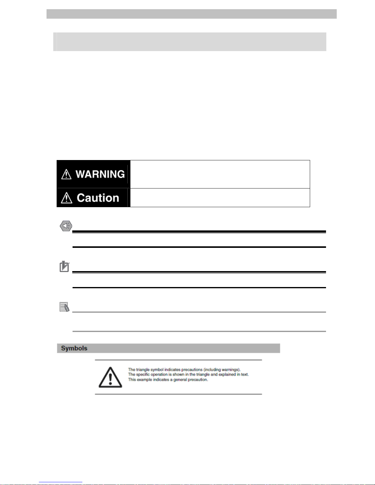
The following notation is used in this document.
Indicates a potentially hazardous situation which, if not avoided,
will result in minor or moderate injury, or may result in serious
injury or death. Additionally there may be significant property
damage.
Indicates a potentially hazardous situation which, if not avoided,
may result in minor or moderate injury or in property damage.
Precautions for Safe Use
Precautions on what to do and what not to do to ensure safe usage of the product.
Precautions for Correct Use
Precautions on what to do and what not to do to ensure proper operation and performance.
Additional Information
Additional information to read as required.
This information is provided to increase understanding or make operation easier.
2
Page 6

4. Overview
4. Overview
This document describes the procedure for connecting the Digital Sensor Communication Unit
(E3NW-ECT) of OMRON Corporation (hereinafter referred to as OMRON) to CJ-series
Programmable Controller + Position Control Unit (hereinafter referred to as the PLC) and
provides the procedure for checking their connection.
Refer to EtherCAT settings described in 7. Connection Procedure to understand the setting
method and key points to connect the devices via EtherCAT.
5. Applicable Devices and Support Software
5.1. Applicable Devices
The applicable devices are as follows:
Manufacturer Name Model
OMRON
CJ2 CPU Unit CJ2[]-CPU[][]
OMRON
Position Control Unit CJ1W-NC[]82
OMRON Digital Sensor Communication Unit E3NW-ECT
OMRON Distributed Sensor Unit E3NW-DS
OMRON
Sensor Amplifiers
Smart Fiber Amplifier
Smart Laser Amplifier Unit
Smart Laser Amplifier Unit (CMOS Type)
E3NX-FA0
E3NC-LA0
E3NC-SA0
Precautions for Correct Use
As applicable devices above, the devices with the models and versions listed in Section 5.2.
are actually used in this document to describe the procedure for connecting devices and
checking the connection.
You cannot use devices with versions lower than the versions listed in Section 5.2.
To use the above devices with versions not listed in Section 5.2 or versions higher than those
listed in Section 5.2, check the differences in the specifications by referring to the manuals
before operating the devices.
Additional Information
This document describes the procedure to establish the network connection. Except for the
connection procedure, it does not provide information on operation, installation or wiring
method. It also does not describe the functionality or operation of the devices. Refer to the
manuals or contact your OMRON representative.
3
Page 7
5. Applicable Devices and Support Software
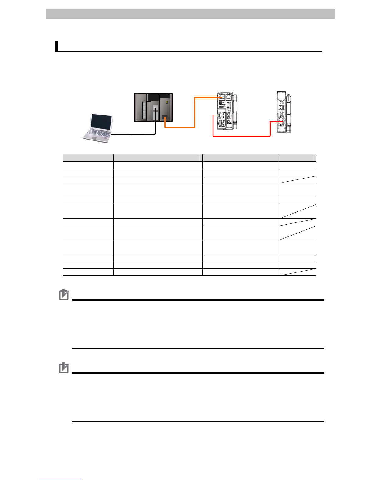
5.2. Device Configuration
The hardware components to reproduce the connection procedure of this document are as
follows.
USB cable
Personal computer
(CX-One installed,
OS:Windows 7)
Ethernet cable
CJ2M-CPU12 +
CJ1W-NCF82
DS-Bu
s
E3NX-F
A0
E3NW-ECT +
E3NX-FA0
E3NW-DS +
Manufacturer Name Model Version
OMRON Position Control Unit CJ1W-NCF82 Ver.1.3
OMRON CPU Unit CJ2M-CPU12 Ver.2.0
OMRON Power Supply Unit CJ1W-PA202
OMRON CX-One CXONE-AL[][]C-V4
/AL[][]D-V4
Ver.4.[][]
OMRON CX-Programmer (Included in CX-One) Ver.9.43
-
Personal computer
(OS: Windows7)
-
- USB cable -
OMRON Ethernet cable (with industrial
Ethernet connector)
XS5W-T421-[]M[]-K
OMRON Digital Sensor Communication
Unit
E3NW-ECT Ver.1.0
OMRON Distributed Sensor Unit E3NW-DS Ver.1.0
OMRON Fiber Amplifier E3NX-FA0 Ver.1.0
- DS-Bus communications cable -
Precautions for Correct Use
The connection line of EtherCAT communication cannot be shared with other Ethernet
networks.
Make sure to directly connect the PLC to the destination device with the Ethernet cable.
Please use the cable (double shielding with aluminum tape and braiding) of Category 5 or
higher, and use the shielded connector of Category 5 or higher.
Precautions for Correct Use
Update the CX-Programmer to the version specified in this section or higher version using the
auto update function.
If a version not specified in this section is used, the procedures described in Section 7 and
subsequent sections may not be applicable. In that case, use the equivalent procedures
described in the CX-Programmer Operation Manual (Cat. No. W466).
4
Page 8

5. Applicable Devices and Support Software
Additional Information
For information on the specifications of the Ethernet cable and network wring, refer to 3-4
Wiring of the CJ-series Position Control Unit Operation Manual (Cat. No. W487).
Additional Information
The system configuration in this document uses USB for the connection between the
personal computer and PLC. For information on how to install the USB driver, refer to A-5
Installing the USB Driver in the CJ-series CJ2 CPU Unit Hardware User's Manual (Cat. No.
W472).
Additional Information
For details on the Inter-Unit DS-Bus network, refer to A-2 Using Distributed Sensor Units of
the EtherCAT
®
Digital Sensor Communication Unit Operation Manual (Cat. No. E429).
5
Page 9

6. EtherCAT Settings
6. EtherCAT Settings
This section describes the procedure for connecting the PLC to the Digital Sensor
Communication Unit via EtherCAT.
6.1. EtherCAT Communications Settings
The settings required for communications between the PLC (Position Control Unit) and the
Digital Sensor Communication Unit are given below.
6.1.1. EtherCAT Communications Setting Contents
The settings required for EtherCAT communications are given below.
PLC (Position Control Unit) Digital Sensor
Communication Unit
Unit number 0 -
Node address - 017
Additional Information
The node addresses 17 onwards are set for CJ1W-NC[]82 when EtherCAT-compatible
devices other than G5-series Servo Drives are connected.
6.2. DS-Bus Communication Settings
The setting required for communications between the Digital Sensor Communication Unit and
the Distributed Sensor Unit is given below.
6.2.1. DS-Bus Communication Setting Contents
The settings required for communications through the Inter-Unit DS-Bus network are given
below.
Distributed Sensor Unit
Unit address 1
Termination setting ON
*The Sensor unit numbers are automatically assigned after turning ON the power supply to the
Digital Sensor Communication Unit and to the Distributed Sensor Unit.
In this document, one Fiber Amplifier is connected to the Digital Sensor Communication Unit
and another one to the Distributed Sensor Unit. The Sensor unit number 1 is assigned to the
Fiber Amplifier that is connected to the Digital Sensor Communication Unit, and the Sensor
unit number 2 is assigned to the Fiber Amplifier connected to the Distributed Sensor Unit.
Additional Information
For details on the Inter-Unit DS-Bus network, refer to A-2 Using Distributed Sensor Units of
the EtherCAT® Digital Sensor Communication Unit Operation Manual (Cat. No. E429).
6
Page 10
6. EtherCAT Settings
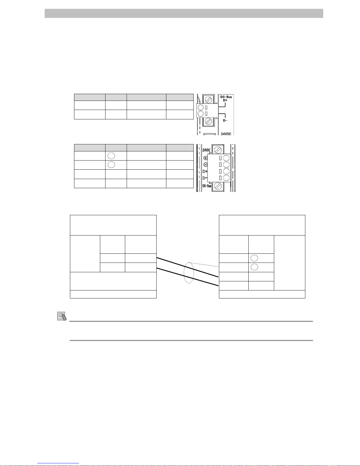
6.2.2. Cable Wiring Diagram
For details on the cable wiring, refer to A-2-3 DS-Bus Network Wiring of the EtherCAT® Digital
Sensor Communication Unit Operation Manual (Cat. No. E429). Check the connector
configuration and pin assignment for wiring.
▪Connector configuration and pin assignment
<OMRON E3NW-ECT> Applicable connector: Terminal-block connector
Pin No Name Description I/O
1 D+
D+ terminal I/O
2 D-
D- terminal I/O
<OMRON E3NW-DS> Applicable connector: Terminal-block connector
Pin No Name Description I/O
1 +
+V terminal
-
2 -
-V terminal
-
3 D+
D+ terminal I/O
4 D-
D- terminal I/O
▪Cable/Pin arrangement
Digital Sensor Communication
Unit (E3NW-ECT)
Distributed Sensor Unit
(E3NW-DS)
Signal
name
Pin No. Pin No. Signal
name
D+ 1 1 +
DS-Bus
D- 2 2 -
7
3 D+
4 D-
DS-Bus
Terminal-block connector Terminal-block connector
Additional Information
For details on the recommended cables and ferrules, refer to A-2-3 DS-Bus Network Wiring
of the EtherCAT
®
Digital Sensor Communication Unit Operation Manual (Cat. No. E429).
Page 11
6. EtherCAT Settings
8
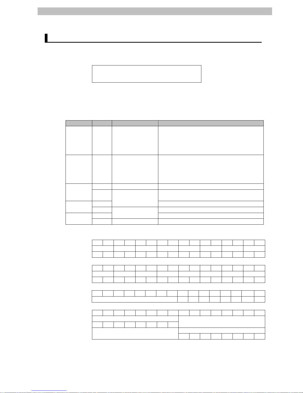
6.3. Allocations of I/O Memory Areas
The I/O allocations of the Digital Sensor Communication Unit are as follows:
Input area
3900
3904
(Digital Sensor Communication Unit → PLC)
10 bytes
▪Details on output area
No output area is allocated.
▪Details on input area
Address Bit Function name Description
3900 15 to 0
Read input
1st word
Sensor unit No. 1 Sensor Input 1
Sensor unit No. 1 Sensor Input 2
Sensor unit No. 8 Sensor Input 1
Sensor unit No. 8 Sensor Input 2
3901 15 to 0
Read input
2nd word
Sensor unit No. 9 Sensor Input 1
Sensor unit No. 9 Sensor Input 2
Sensor unit No. 16 Sensor Input 1
Sensor unit No. 16 Sensor Input 2
7 to 0 Sensor Status bits Sensor status
3902
15 to 8 Number of Sensors setting (register at
power-on)
7 to 0
Connecting
Sensor bits
Number of Sensors setting with dummy
3903
15 to 8 Warning status (Sensor unit No. 1 to 8)
7 to 0
Sensor Status
16 bits
Warning status (Sensor unit No. 9 to 16)
3904
15 to 8 Reserved Reserved
•Read input 1st word
15 14 13 121110987654 3 2 10
3900
Sensor 8 Sensor 7 Sensor 6 Sensor 5 Sensor 4 Sensor 3 Sensor 2 Sensor 1
IN2 IN1 IN2 IN1 IN2 IN1 IN2 IN1 IN2 IN1 IN2 IN1 IN2 IN1 IN2 IN1
•Read input 2nd word
15 14 13 121110987654 3 2 10
3901
Sensor 16 Sensor 15 Sensor 14 Sensor 13 Sensor 12 Sensor 11 Sensor 10 Sensor 9
IN2 IN1 IN2 IN1 IN2 IN1 IN2 IN1 IN2 IN1 IN2 IN1 IN2 IN1 IN2 IN1
•Sensor Status bits
15 14 13 121110987654 3 2 1 0
3902
(Number of Sensors setting) 0 0 0 0 0 0 S_ERR BUSY
•Sensor Status(Warning Status) 16 bits
15 14 13 121110987654 3 2 10
3903
Sensor unit No.
7 6 5 43210
(Number of Sensors)
3904
Sensor unit No.
(Reserved)
15 14 13 12 11 10 9 8
Page 12

6. EtherCAT Settings
Additional Information
The default first words of the Remote I/O Output Memory Area and the Remote I/O Input
Memory Area are CIO 3800 and CIO 3900, respectively.
For how to change the allocations of the Remote I/O Memory Areas, refer to 6-3 Common
Parameters of the CJ-series Position Control Unit Operation Manual (Cat. No. W487).
Additional Information
For details on the PDO mapping of the Digital Sensor Communication Unit, refer to 5-4-4
PDO Mapping of the EtherCAT
®
Digital Sensor Communication Unit Operation Manual (Cat.
No. E429).
9
Page 13

7. Connection Procedure
10
7. Connection Procedure
This section describes the procedure for connecting the PLC to the Digital Sensor
Communication Unit via EtherCAT.
This document explains the procedure for setting up the PLC and the Digital Sensor
Communication Unit from the factory default setting. For the initialization, refer to Section 8
Initialization Method.
7.1. Work Flo w
Take the following steps to connect to the Digital Sensor Communication Unit via EtherCAT.
7.2. Setting Up the Digital Sensor
Communication Unit
Set up the Digital Sensor Communication Unit and
Distributed Sensor Unit.
↓
7.2.1 Hardware Settings
Set the hardware switches on the Digital Sensor
Communication Unit and Distributed Sensor Unit.
↓
7.3. Setting Up the PLC
Set up the PLC.
↓
7.3.1. Hardware Settings Set the hardware switches on the Position Control
Unit.
↓
7.3.2. Starting the CX-Programmer
and Connecting online with the
PLC
Start the CX-Programmer and connect online with
the PLC.
↓
7.3.3. Creating the I/O Table Create the I/O table for the PLC.
↓
7.3.4. Creating the network
configuration and transferring
Set up the network and transfer the settings.
↓
7.4. Checking the EtherCAT
Communications
Confirm that the EtherCAT communications are
performed normally.
↓
7.4.1 Checking the Connection Status
Check the connection status of the EtherCAT
network.
↓
7.4.2 Checking Data that are Sent and
Received
Confirm that correct data are sent and received.
Page 14

7. Connection Procedure
7.2. Setting Up the Digital Sensor Communication Unit
Set Up the Digital Sensor Communication Unit.
7.2.1. Hardware Settings
Set the hardware switches on the Digital Sensor Communication Unit.
Precautions for Correct Use
Make sure that the power supply is OFF when you perform the setting up.
1
Confirm that the power supply to
the Digital Sensor
Communication Unit is OFF.
*If the power supply is turned
ON, settings may not be
applicable as described in the
following procedure.
2
Connect the Digital Sensor
Communication Unit to the Fiber
Amplifier, and attach the
protective cap.
Check the hardware switches on
the Digital Sensor
Communication Unit by referring
to the figure on the right.
3
Set the node address switches
as follows.
100: 0
10: 1
1: 7
*Set the node address to 017.
Di
g
ital Sensor Communication
Fiber Amplifier
Protective cap
Node address switches
Node address setting
(
1)
Node address setting
(
10)
Node address setting
(
100
)
11
Page 15

7. Connection Procedure
4
Connect the Distributed Sensor
Unit to the Fiber Amplifier, and
attach the protective cap.
Check the hardware switches on
the Distributed Sensor Unit by
referring to the figure on the
right.
5
Set the termination switch to
ON.
This switch turns ON and OFF the communications terminating resistance on
the Inter-Unit DS-Bus network.
Turn ON the DS-Bus termination switch only on the last Distributed Sensor
Unit on the DS-Bus network. Turn it OFF on all other Distributed Sensor Units.
6
Set the unit address switch to 1.
*Set the unit address to 1.
This switch sets the node address (decimal) that the E3NW-DS will use on
the Inter-Unit DS-Bus network.
The setting range is from 1 to 8. (Default setting: 1)
If you connect more than one Distributed Sensor Unit to the Sensor
Communication Unit, set the address for each Distributed Sensor Unit to
consecutive numbers starting from 1.
7
Connect the Digital Sensor
Communication Unit to the
Distributed Sensor Unit with the
DS-Bus communications cable.
*For the wiring of the DS-Bus
communications cable, refer to
6.2.2. Cable Wiring Diagram.
8
Connect the Ethernet cable to
CN IN connector.
Turn ON the power supply.
Unit numbers are assigned to
the Fiber Amplifier as follows
after turning ON the power
supply.
Digital Sensor Communication
Unit: Sensor unit No. 1
Distributed Sensor Unit:
Sensor unit No. 2
Distributed Sensor
Fiber Amplifier
Termination switch
Unit address switch
Protective ca
p
DS-Bus
communications
cable
Power
supply
Power
supply
CN IN connector
12
Page 16

7. Connection Procedure
7.3. Setting Up the PLC
Set up the PLC.
7.3.1. Hardware Settings
Set the hardware switches on the Position Control Unit.
Precautions for Correct Use
Make sure that the power supply is OFF when you perform the setting up.
1
Make sure that the power supply
to the PLC is OFF.
*If the power supply is turned
ON, settings may not be
applicable as described in the
following procedure.
2
Check the hardware switches on
the front panel of the Position
Control Unit by referring to the
right figure.
3
Set the Unit No. Switch to 0.
4
Connect each PLC unit in order
from the Power Supply Unit,
CPU Unit, Position Control Unit
and End Cover.
Connect the Ethernet cable to
the Position Control Unit and
connect the USB cable to the
CPU Unit.
After connecting, turn ON the
power supply to the PLC.
Indicators
Show the operating status of the Position Control Unit.
Unit Number Switch
Set the unit number of the Position Control Unit.
EtherCAT Communications Connector
Connect to the EtherCAT Communications Cable.
Indicators and Display
Show the EtherCAT communications status.
Ethernet
cable
End Cove
r
Position
Control Unit
Power
Supply Unit
CJ-series
CPU Unit
USB Cable
13
Page 17

7. Connection Procedure
7.3.2. Starting the CX-Programmer and Connecting Online with the PLC
Start the CX-Programmer and Connect Online with the PLC.
Install the CX-One and USB driver in the personal computer beforehand.
1
Start the CX-Programmer.
2
Select Auto Online - Direct
Online from the PLC Menu.
3
The Direct Online Dialog Box is
displayed. Select the USB
Connection Option for
Connection Type and click the
Connect Button.
14
Page 18

7. Connection Procedure
4
The dialog box on the right is
displayed. Check the message
on the dialog and if there is no
problem, click the No Button.
5
The dialog box on the right is
displayed, and the
CX-Programmer and the PLC is
automatically connected.
6
Confirm that the
CX-Programmer and the PLC
are normally connected online.
*The
icon is shown during
online connection.
Additional Information
If the CX-Programmer and PLC are not connected online, please check the connection of the
cable. Or, return to step 2, check the settings and repeat each step.
Refer to Connecting Directly to a CJ2 CPU Unit Using a USB Cable in Chapter 3
Communications in PART 3: CX-Server Runtime of the CX-Programmer Operation Manual
(Cat. No. W466) for details.
Additional Information
The dialogs explained in the following procedures may not be displayed depending on the
environmental setting of CX-Programmer.
For details on the environmental setting, refer to Options and Preferences in Chapter 3
Project Reference in PART 1: CX-Programmer of the CX-Programmer Operation Manual
(Cat. No. W466). This document explains the setting procedure when the Confirm all
operations affecting the PLC Check Box is selected.
15
Page 19

7. Connection Procedure
7.3.3. Creating the I/O Table
Create the I/O table for the PLC.
1
If the operating mode of the PLC
is RUN Mode or Monitor Mode,
change it to Program Mode, by
following steps (1) to (3).
(1)Select Operating Mode -
Program from the PLC Menu
of the CX-Programmer.
(2)The dialog box on the right is
displayed. Check the
message on the dialog and if
there is no problem, click the
Yes Button.
*Refer to Additional Information
in 7.3.2. Starting the
CX-Programmer and
Connecting Online with the PLC
for the settings concerning the
dialog display.
(3)Confirm that Stop/Program
Mode is displayed on the right
of the PLC model in the
project workspace of the
CX-Programmer.
2
Select Edit - I/O Table and Unit
Setup from the PLC Menu of the
CX-Programmer.
The PLC IO Table Window is
displayed.
16
Page 20

7. Connection Procedure
3
Select Create from the Options
Menu of the PLC IO Table
Window.
The dialog box on the right is
displayed. Check the message
on the dialog and if there is no
problem, click the Yes Button.
The dialog box on the right is
displayed. Check the message
on the dialog and if there is no
problem, click the Yes Button.
17
Page 21

7. Connection Procedure
4
The Transfer from PLC Dialog
Box is displayed. Select the I/O
Table Check Box and the SIO
Unit Parameters Check Box,
and click the Transfer Button.
The Transfer from PLC Dialog
Box is displayed.
Confirm that the transfer was
normally executed by checking
the message in the dialog box.
When the I/O table is created
normally, the dialog box shows
the following:
Transfer Success: 1 Unit
Transfer Unsuccessful: 0 Unit
Click the OK Button.
Precautions for Correct Use
Confirm that the Ethernet cable is connected before proceeding to the following procedure.
If it is not connected, turn OFF the power supply to each device, and then connect the
Ethernet cable.
18
Page 22

7. Connection Procedure
7.3.4. Creating the Network Configuration and Transferring
Create the network configuration and transfer the settings.
1
Double-click the [0000] Main
Rack on the PLC IO Table
Window to expand the tree.
2
Right-click 00[1500]CJ1W-NCF82
and select the Unit Setup.
3
The Network Auto Setup Dialog
Box is displayed. Check the
message on the dialog and if there
is no problem, click the OK Button.
*If the dialog box is not displayed,
select Network Auto Setup from
the Network Menu in the PCU
Setting Window.
*Close any other dialog box such
as the Monitor Dialog Box if
displayed.
(PCU Setting Window)
Parameter
setting view
Tree
view
Network Auto Setup Dialog Box
Additional Information
The node addresses 17 onwards are set for CJ1W-NC[]82 in order from the addresses that
were set when EtherCAT-compatible devices other than G5-series Servo Drives are
connected.
19
Page 23

7. Connection Procedure
4
The dialog box on the right is
displayed. Select the Fixed
Allocations Option and click the
OK Button.
5
The network configuration is set
up automatically. Confirm that the
node address 17 is set for
E3NW-ECT Communication Unit
for Digital Type Sensor 60 inputs,
and click the OK Button.
20
Page 24

7. Connection Procedure
6
The dialog box on the right is
displayed. Check the message on
the dialog and if there is no
problem, click the OK Button.
*If a confirmation dialog box is
displayed, check the message
and if there is no problem, click
the OK Button.
The dialog box on the right is
displayed. Check the message on
the dialog and if there is no
problem, click the OK Button.
The dialog box on the right is
displayed. Check the message on
the dialog and if there is no
problem, click the OK Button.
21
Page 25

7. Connection Procedure
7
The PCU Setting Window is
displayed. Select Network
Setting from the project tree on
the left side of the Window.
Confirm that #17_New Slave
E3NW-ECT Communication Unit
for Digital Type Sensor 60
inputs(V1.0) was added.
*The model and version may differ
depending on the device used.
8
Click the Remote I/O Input/Output
Memory Area Allocation List Tab
that is on the right side on the PCU
Parameter Setting Window.
Confirm that node address #17 is
displayed and the I/O Memory
Areas are set as follows:
•Input offset: 0
•Input address: 3900
•Input size: 10 bytes
•Output offset: -
•Output address: -
•Output size: 0 byte
9
Select Verify Network from the
Network Menu.
10
Confirm that Matched is displayed
on the Network Verification Result
Dialog Box, and click the OK
Button.
22
Page 26

7. Connection Procedure
7.4. Checking the EtherCAT Communications
Confirm that the EtherCAT communications are performed normally.
7.4.1. Checking the Connection Status
Check the connection status of the EtherCAT network.
1
Check the LED indicators on the
Position Control Unit and confirm
that the EtherCAT communications
are performed normally.
LED indicators in normal status:
[RUN]: Lit green
[ERC]: Not lit
[ERH]: Not lit
[ECAT RUN]: Lit green
[ECAT ERR]: Not lit
[L/A]: Flickering
The 7-segment display shows as
follows during normal EtherCAT
communications.
The 7-segment display: 00 Lit
(During EtherCAT
communications)
The status of each LED indicator is
shown on the right.
(Upper side of Position Control Unit)
(Lower side of Position Control Unit)
23
Page 27

7. Connection Procedure
2
Check the LED indicators on the
Digital Sensor Communication Unit.
LED indicators in normal status:
[PWR]: Lit green
[L/A IN]: Flickering
[L/A OUT]: Not lit (last slave)
[RUN]: Lit green
[ERR]: Not lit
[SS]: Lit green
(Digital Sensor Communication Unit)
24
Page 28

7. Connection Procedure
3
Check the LED indicators on the
Distributed Sensor Unit.
LED indicators in normal status:
[RUN]: Lit green
[SS]: Lit green
(Distributed Sensor Unit)
Additional Information
For details on errors in the Position Control Unit, refer to Section 13 Troubleshooting of the
CJ-series Position Control Unit Operation Manual (Cat. No. W487).
Additional Information
For details on errors in the Digital Sensor Communication Unit and the Distributed Sensor
Unit, refer to Chapter 8 Troubleshooting and Maintenance of the EtherCAT® Digital Sensor
Communication Unit Operation Manual (Cat. No. E429).
25
Page 29

7. Connection Procedure
7.4.2. Checking Data that are Sent and Received
Confirm that correct data are sent and received.
Confirm safety sufficiently before monitoring power flow and present value
status in the Ladder Section window or before monitoring present values in the
Watch window.
If force-set/reset or set/reset operations are incorrectly performed by pressing
short-cut keys, the devices connected to Output Units may malfunction,
regardless of the operating mode of the CPU Unit.
1
Confirm that the PLC is in
PROGRAM mode.
*If the PLC is not in the PROGRAM
mode, change to PROGRAM mode
by referring to step 1 of 7.3.3.
Creating the I/O Table.
2
Select Edit - Memory from the PLC
Menu.
26
Page 30

7. Connection Procedure
3
Double-click CIO from the list in the
PLC Memory Window that is
displayed.
4
Select Display - Hexadecimal from
the View Menu.
5
Select Monitor from the Online
Menu.
6
The Monitor Memory Areas Dialog
Box is displayed.
Select the CIO Check Box and click
the Monitor Button.
27
Page 31

7. Connection Procedure
7
Check the display contents of the
Fiber Amplifier.
The LED indicators in the figure on
the right show as follows:
Outputs of Sensor unit No. 1
IN2[2]: Lit orange (ON)
IN1[1]: Lit orange (ON)
*They are the outputs of the Fiber
Amplifier connected to the Digital
Sensor Communication Unit.
Outputs of Sensor unit No. 2
IN2[2]: Lit orange (ON)
IN1[1]: Lit orange (ON)
*They are the outputs of the Fiber
Amplifier connected to the
Distributed Sensor Unit.
Digital Sensor Communication Unit and Fiber
Amplifier (Sensor unit No. 1)
Distributed Sensor Unit and Fiber Amplifier
(Sensor unit No. 2)
8
Enter 3900 in the Start Address
Field on the CIO Window.
Confirm that the start address was
changed to 3900.
The right example shows as follows:
CIO 3900: 000F (IN1 and IN2 of
Sensor unit No. 1 and 2
are turned ON.)
CIO 3902: 0200 (BUSY: OFF,
S_ERR: OFF, Number of
Sensors setting: 2)
CIO 3903: 0002
(Number of Sensors: 2)
Fiber Amplifier
Digital Sensor Communication Unit
Distributed Sensor Unit
IN2
IN1
IN2
IN1
Fiber Amplifier
28
Page 32

8. Initialization Method
8. Initialization Method
This document explains the setting procedure from the factory default setting.
Some settings may not be applicable as described in this document unless you use the
devices with the factory default setting.
8.1. Initializing the PLC
To initialize the PLC, it is necessary to initialize the CPU Unit and the Position Control Unit.
Change to the PROGRAM Mode before initialization.
8.1.1. Position Control Unit
(1)Select Edit - I/O Table and Unit Setup from the PLC Menu of the CX-Programmer. On the
PLC IO Table Dialog Box, right-click the Position Control Unit and select Unit Setup from the
menu.
(2)The PCU Parameter Setting Window is displayed. Select Initialize Memory from the NC
Unit Menu.
29
Page 33

8. Initialization Method
8.1.2. CPU Unit
To initialize the settings of the CPU Unit, select Clear All Memory Areas from the PLC
Menu of the CX-Programmer. On the Confirm All Memory Area Clear Dialog Box, select
the Initialize Option and click the OK Button.
30
Page 34

9. Revision History
31
9. Revision History
Revision
code
Date of revision Revision reason and revision page
01 2013/06/07 First edition
Page 35

32
Page 36

2013
0911(-)
P562-E1-01
 Loading...