

Page 1
Note: If you only want to connect one SSI encoder, the other SSI
channel has to be disabled in DM m+20, see section Configuring the
Unit via DM for further details.
PNSPO
Model
CJ1W-CTS21-E
Synchronous Serial Interface (SSI) Unit
INSTRUCTION SHEET
Thank you for purchasing an OMRON product. Read this
instruction sheet thoroughly and familiarise yourself with the
functions and characteristics of the product before using it. To
ensure safe and correct use of this Unit, also read the following
Operation Manual (Cat. No. W393-E1): SYSMAC CJ1 Series
Programmable Controllers.
Keep this instruction sheet for future reference.
OMRON MANUFACTURING OF THE NETHERLANDS B.V.
OMRON Corporation 2004 All Rights Reserved
1634330-1A
Unit specifications
Unit type CJ1 Special I/O Unit
Applicable PLC models CJ1-series PLCs
Storage temperature -20 to +75 °C
Ambient temperature 0 to +55 °C
Ambient humidity 10 to 90 % (non-condensing)
EMC compliance EN 50081-2, EN 61131-2
Current consumption 300 mA (5V via busconnection)
Weight 200 g (typical)
Number of words
allocated
• 20 CIO-words. First word
allocated = CIO2,000 + (Nx10)
• 30 DM-words. First word
allocated = D20,000 + (Nx100)
Dimensions
EXT.PS FOR ENCODERS: 5-24 V DC, 0.8 A max.
CTS21
100x
10x
1
RUN
CH1
CH2
ERC ERH
B1 A1
MACH
No
CJ1W-CTS21-E
SSI DATA+CLK:RS-422 Line Driver, 1.5 MHz max.
2-CHANNEL SSI UNIT
PNSPO
OMRON MANUFACTURING OF THE NETHERL ANDS B.V.
MADE IN THE NETHERLANDS
Lot No. 000000N0000 Batch No. 000000000
31
65
24
90
95
! DANGER
Do not attempt to take the Unit apart and do not
touch any internal parts while the power is being
supplied. Doing either of these may result in
electrical shock, and serious or fatal injury.
! Caution
Leave the protective label on top of the Unit as long
as the Unit is not mounted and wired completely, in
order to prevent wire clippings or other materials
from getting inside the Unit. When the mounting and
wiring has been completed, the label must be
removed to allow air circulation and heat radiation.
LED Indicators
Name Colour State Unit status
RUN green On Normal operation
Off Initialisation error
ERC red On Unit error (check CIO n+6, n+7)
Off Unit has no errors
ERH red On CJ1-CPU Unit error
Off CJ1-CPU Unit has no errors
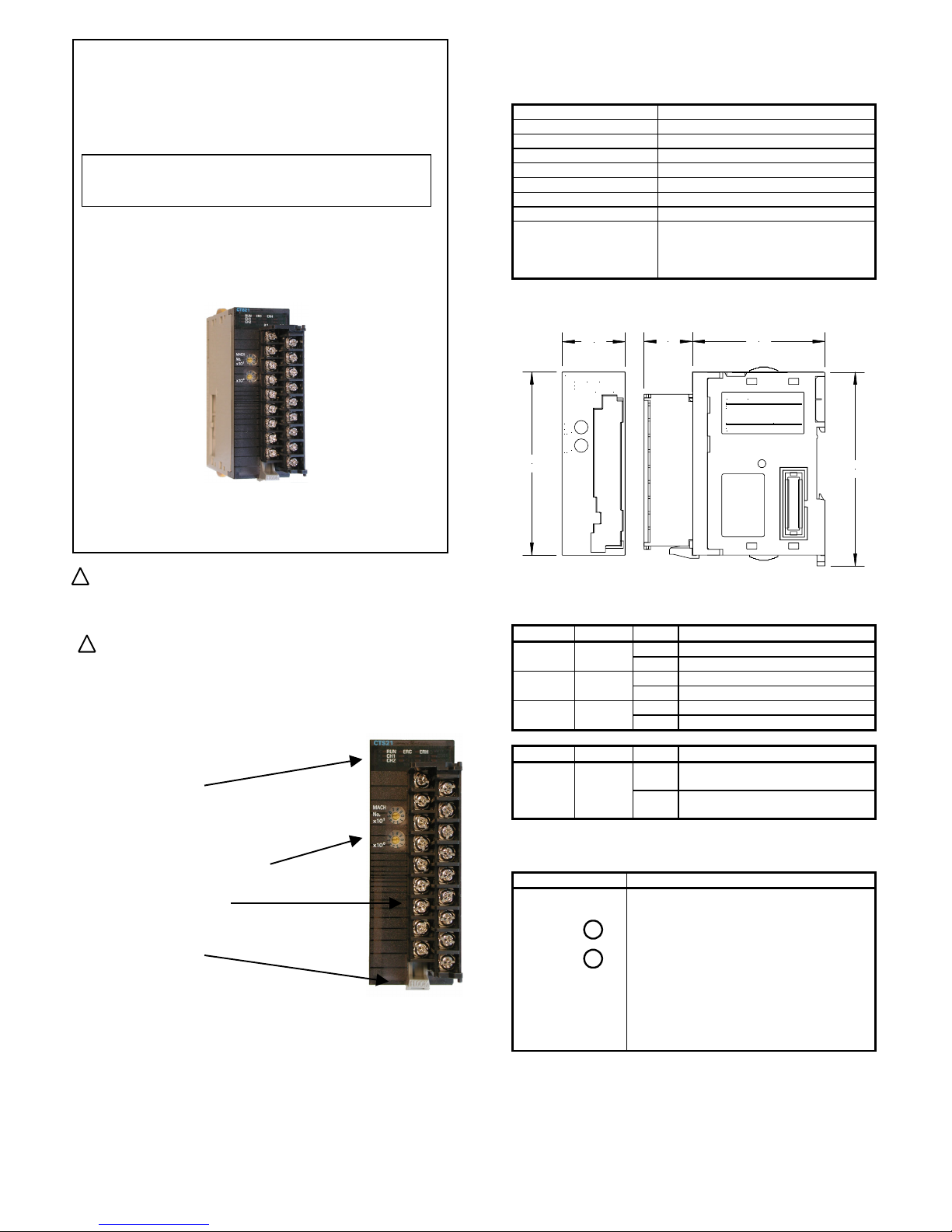
Nomenclature
Unit status indicators
• RUN (green)
• ERC (red)
• ERH (red)
• CH1, CH2 (green)
Machine number rotary switches
Removable Terminal Block
• Connections for SSI-encoders
• Connection for power supply SSI-encoders
Terminal Block latch
• Slide down to remove
Name Colour State Counter channel status
CH1,
CH2
green On Channel configured and is
communicating without errors
Off Channel is not configured or a
communication error has occurred
Machine Number Switch
Name Function
MACHINE No.
Sets the Machine Number (00 – 94).
• Setting Machine Numbers 95-99 will
generate an error.
• Make sure each Machine Number is
used only once per CJ1-CPU.
• The next higher Machine Number should
not be used on any unit, as it would
cause a CIO-data overlap
• Be sure to turn off the power to the Unit
before setting the Machine Number.
x10
x10
1
0
• Slide up to lock
Quick Start
1. Set all DM-settings to 0. The Unit is now configured as follows:
400kHz clock frequency, 24 bit Gray-coded and a 40µs
monoflop time, for both SSI channels.
2. Set Machine Number.
3. Mount and wire the Unit, the two SSI encoders and the
encoders power supply.
4. Turn power on.
5. Create I/O Table.
6. Both green CH1 and CH2 indicators should now turn on.
7. The encoder data can now be read from CIO n+10/11 and CIO
n+15/16.
1
Page 2
Terminal Block layout
Notes:
• Electrical isolation is provided for each data input line. Electrical
isolation is not provided for the outgoing clock lines. The
encoder power supply can be connected to the unit’s connector.
Use the following table to make connections directly to the screw
terminals block:
• The power supply should match the encoders specifications.
Item Description
Row B
Terminal
no.
Description
Row A
SSI DATA CH1 DATA1 - B1
A1 DATA1 +
SSI Clock CH1 CLOCK1 - B2
A2 CLOCK1 +
SSI Power Supply
OUT CH1
0V_ENC_PS¹ B3
A3 +_ENC_PS2
N.C. B4
A4 N.C.
SSI DATA CH2 DATA2 - B5
A5 DATA2 +
SSI Clock CH2 CLOCK2 - B6
A6 CLOCK2 +
SSI Power Supply
OUT CH2
0V_ENC_PS¹ B7
A7 +_ENC_PS2
N.C. B8
A8 N.C.
Encoder Power
Supply Input
0V_ENC_PS¹ B9
A9 +_ENC_PS2
• Use shielded twisted pair, 2×2×0.25mm
2
(+ optional 2×0.5mm2
for PS).
• The shield must be connected to the SSI encoder and to the
frame-ground near the PLC-system.
• The SSI protocol has no mechanism to reject noise. See section
Noise Prevention for more information.
• Recommended maximum cable length by selected clock
frequency:
100kHz: < 400m
300kHz: < 100m
200kHz: < 200m
400kHz: < 50m.
Communication Errors
During normal operation, the SSI Unit can detect three kinds of
communication errors (see section Error Processing). At the
occurrence of a communication error on channel 1(2):
• the corresponding error code is set in CIO n+6, n+7
• the corresponding error code is stored inside the SSI Unit
• the Global Error Indication bit in CIO (n+8, bit 00) is set
• the ERC-LED is turned on
• the corresponding CH1(2)-LED is turned off
This status will remain, even if during the next SSI-communication no
error is detected by the SSI Unit. In this case only the “New valid SSI
data received” bit in CIO will be set, indicating that for the current SSI
data in CIO no communication error was detected.
(1)(2): All these pins are internally connected.
To clear the above error status, the “Clear Error” bit in CIO has to be
set.
The following table describes the possible statuses of the SSI Unit
after proper initialisation:
SSI Communication
ERC
LED /
Global
error bit
CH
LED
New
Valid
SSI data
received
bit
Status
Off On On
The channel SSI data in CIO can
be used; no error has occurred.
Off On Off
No new channel SSI data has
been received since last cyclic
refresh; no error has occurred.
Off Off Off
Channel is not configured for SSI
communication (see DM m+10/20).
On Off On
The channel SSI data in CIO can
be used; a communication error
has occurred earlier *.
On Off Off
The channel SSI data in CIO
cannot be used; a communication
error has occurred *.
On On On
The channel SSI data in CIO can
be used; a non-communication
error has occurred *.
On On Off
No new channel SSI data has
been received since last cyclic
refresh; a non-communication error
has occurred *.
Item Specification
CLK lines Non-isolated differential line driver,
RS422 compliant
DATA lines Electrically isolated differential line
receiver, RS422 compliant
Number of data-bits 9 to 31 (default: 24)
Value coding Gray/Binary/Tannenbaum/Raw
(default Gray)
Clock frequency 100kHz to 1.5MHz (default 400kHz)
Monoflop time 10µs to 99,990µs (default: 40µs)
Sample rate Approx. 2500 Samples/sec with 2
encoders connected
(with default settings)
Default: All DM-settings are 0000
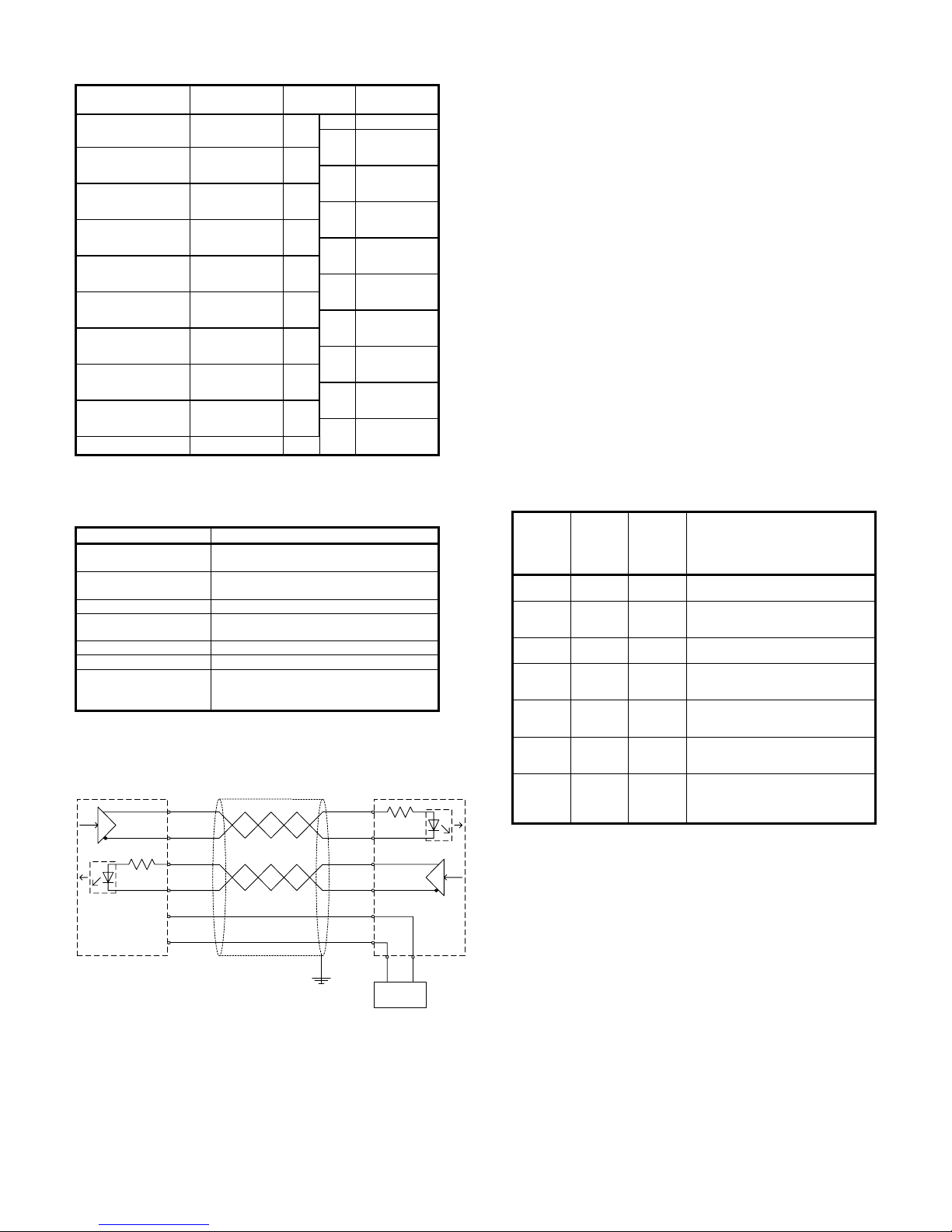
SSI Circuitry
DATA+
DATA-
CLOCK+
CLOCK-
+_ENC_PS
0V_ENC_PS
Shielded Twisted-pair Cable
SSI ENCODER CJ1W-CTS21-E
B3
A3
B2
A2
B1
A1
ENCODER
PS
B9 A9
+
-
RS422
+
-
RS422
* See Error Processing section for countermeasures.
Noise Prevention
The symptoms of picking up noise are random jumps in the SSI data
values read (CIO n+10/11 and n+15/16). For applications that expect
a continuous change of SSI data values, the PLC application can e.g.
identify noise by detecting an unexpected large change in the SSI
data values or data values outside the expected range.
The best way to prevent noise is by proper wiring the unit as
described in the SSI Communication section.
An alternative could be to use an SSI encoder equipped with parity.
2
Page 3

Configuring the Unit via DM Operating the Unit via CIO
m = D20000 + (Nx100), with N the Machine Number of the Unit. n = CIO2000 + (Nx10), with N the Machine Number of the Unit.
DM Word Bit Function
General
m 00-15 Reserved*
m+1 00-15 Reserved*
m+2 00-15 Reserved*
m+3 00-15 Reserved*
m+4 00-15 Reserved*
m+5 00-15 Reserved*
m+6 00-15 Reserved*
m+7 00-15 Additional SSI-communication start-up
delay **:
0 = 2000ms delay
1 = 1050ms delay
2 = 500ms delay
3 = no delay
m+8 to
m +9
00-15 Reserved*
SSI Channel 1 ***
m+10 00-15 SSI baudrate:
0 = 400kHz
1 = 100kHz
2 = 200kHz
3 = 300kHz
4 = 400kHz
5 = 500kHz
6 = 1MHz
7 = 1.5MHz
FFFF = No encoder connected (the rest of
settings is not processed)
m+11 00-15 Value coding:
0 = Gray code
1 = Binary
2 = Raw SSI data only (settings m+13..16
are not processed)
m+12 00-15 Encoder resolution:
Number of data bits: [9..31] (in BCD), 0
means value = 24 bits
m+13 00-15 Leading bits ****:
Number of bits preceding encoder data:
[0..31] (in BCD)
Σ m+12..13 ≤ 31
m+14 00-15 Trailing bits ****:
Number of bits following encoder data:
[0..31] (in BCD)
Σ m+12..14 ≤ 31
m+15 00-15 Optional SSI encoder status bits (see CIO
n+12 bits 00-07):
Number of bits succeeding trailing bits:
[0..8]
Σ m+12..15 ≤ 31
00-07 Parity check:
0 = no parity check
1 = check for even parity
2 = check for odd parity
Parity is calculated over all bits received.
m+16
08-15 Not used
m+17 00-15 Mono-flop time: check if the data line is
high after the mono-flop time has expired.
Set in tens of microseconds (BCD).
m+18 00-15 Reserved*
m+19 00-15 Reserved*
SSI Channel 2 ***
m+20 to
m+29
00-15 Same as SSI channel 1, see m+10 to
m+19
Word
(output)
Bit Function
General
n 00-15 Reserved*
00
Read (next) Error (0→1) from error history
01
Clear all Errors (0→1) from error history
n+1
02-15 Reserved*
n+2 00-15 Reserved*
n+3 00-15 Reserved*
n+4 00-15 Reserved*
n+5 00-15 Reserved*
n+6, 00-15
n+7
Error Code (See Error Processing section for
details)
00 Global Error Indication
01 Reserved*
02 Unit initialising after restart or power-up
n+8
03-15 Reserved*
n+9 00-15 Reserved*
SSI Channel 1
n+10,
n+11
00-15 Current SSI data
00-07 Optional SSI encoder status (see DM m+15)
08 Valid SSI data received since previous I/O-
refresh
n+12
09-15 Reserved*
n+13,
n+14
00-15 Reserved*
SSI Channel 2
n+15,
n+16
00-15 Current SSI data
00-07 Optional SSI encoder status (see DM m+25)
08 Valid SSI data received since previous I/O-
refresh
n+17
09-15 Reserved*
n+18,
n+19
00-15 Reserved*
Reserved*: Address should not be used, value must be 0000
Reserved*: Address should not be used, value must be 0000
** This delay is additional to the PLC-system start-up time.
*** Refer to the operation manual of the SSI encoder for proper
configuration of the SSI Unit’s channels.
**** Trailing and leading bits are to be used for connecting Tannen-
baum coded SSI-encoders. E.g. for a 24-bit Tannenbaum
encoder with 10 multi-turn and 10 single turn-bits and 1 status
bit, centred around bit 12/13, the leading bits have to be set to 2
and the trailing bits to 2.
3
Page 4

Error Processing
At the occurrence of an error:
• the corresponding error code is transferred to words CIO n+6,
n+7
• the corresponding error code is stored inside the SSI Unit
• the Global Error Indication bit in CIO (n+8, bit 00) is set
• the ERC-LED or ERH-LED is turned on
The following errors codes can be reported in CIO n+6, n+7:
n+6 n+7 Description
0300 DM
Offset
The DM-setting located at
D20000 + (Nx100) + DM Offset
is Out of Range
(N = Machine Number).
0310 DM
Offset
The DM-setting located at
D20000 + (Nx100) + DM Offset
is an invalid BCD-code
(N = Machine Number).
(The range of a valid BCD-code for a digit
is 0-9. If one or more digits is within range
A - F an invalid BCD-code is specified).
Countermeasure: DM-configuration errors can be cleared by
correcting the faulty settings in Data Memory and transferring the new
configuration data to the Unit. To transfer the configuration data::
• Turn the power of the CJ1-system ON, or
• Restart the Unit using Restart-Bits A50200 to 50715
n+6 n+7 Description
0490 CH
No.
00 Parity error in SSI channel CH No.
Countermeasure: Check if the unit is configured to check for the
correct type of parity (even or odd). Check the SSI-encoder.
n+6 n+7 Description
0490 CH
No.
01 SSI-encoder channel CH No. not ready
Countermeasure: This error appears in case the data line is low right
before the communication with the encoder connected to channel CH
No. is started. Check the cabling between the unit and the SSIencoder. Check the SSI-encoder.
n+6 n+7 Description
0490 CH
No.
02 SSI-encoder channel CH No. time-out
Countermeasure: This error appears in case the data line is and stays
low after the mono-flop time has expired on channel CH No.
Check if
the unit is configured for the correct encoder settings. Check the
cabling between the unit and the SSI-encoder. Check the SSIencoder.
n+6 n+7 Description
0002 Time-out in
ms (hex)
A cyclic refresh time-out error was
generated caused by a PLC system error or
you have chosen to disable the Cyclic
Refresh of the SSI Unit in the CJ1-PLC
settings. This error will be cleared as soon
as Cyclic Refresh or IORF will take place.
000E 0000 An error has occurred on the I/O Bus
causing the SSI Unit to be in an undefined
state. On occurrence of an I/O Bus error
you can configure the Outputs to keep their
last state or to have a predefined state
(refer to DM m/m+1)
Countermeasure: Turn ON the power supply again or restart the
system. If the error persists then replace the CJ1-CPU.
PNSPO
OMRON EUROPE B.V.
Wegalaan 67-69
NL-2132 JD Hoofddorp
The Netherlands
Phone (+31) 23 - 56 81 300
Fax (+31) 23 - 56 81 388
Internet: www.eu.omron.com
Note: Specification subject to change without notice.
1634330-1A
Printed in The Netherlands
4
 Loading...