

Page 1

Cat. No. W02E-EN-01
SYSMAC CJ-series
CJ1W-CTL41-E
4-Channel Counter Unit
OPERATION MANUAL
Page 2

SYSMAC CJ-series
CJ1W-CTL41-E
4-Channel Counter Unit
Operation Manual
Produced September 2004
i
Page 3

ii
Page 4

Notice:
OMRON products are manufactured for use according to proper procedures by a qualified operator and
only for the purposes described in this manual.
The following conventions are used to indicate and classify precautions in this manual. Always pay attention to the information provided with them. Failure to comply with the precautions can result in injury to people or damage to the product.
!DANGER Indicates an imminently hazardous situation which, if not avoided, will
result in death or serious injury.
!WARNING Indicates a potentially hazardous situation which, if not avoided, could
result in death or serious injury.
!Caution Indicates an potentially hazardous situation which, if not avoided, may
result in minor or moderate injury, or property damage.
OMRON Product References
All OMRON products are capitalised in this manual. The word “Unit” is also capitalised when it refers to an
OMRON product, regardless of whether or not it appears in the proper name of the product.
The abbreviation “Ch,” which appears in some displays and on some OMRON products, often means
“word” and is abbreviated “Wd” in documentation in this sense.
The abbreviation “PLC” means Programmable Logic Controller and is not used as an abbreviation for anything else.
Visual Aids
The following headings appear in the left column of the manual to help you locate different types of information.
1, 2, 3… Indicates lists of one sort or another, such as procedures, checklists, etc.
©
OMRON, 2004
All rights reserved. No part of this publication may be reproduced, stored in a retrieval system, or transmitted, in any
form, or by any means, mechanical, electronic, photocopying, recording, or otherwise, without the prior written
permission of OMRON.
No patent liability is assumed with respect to the use of the information contained herein. Moreover, because
OMRON is constantly striving to improve its high-quality products, the information contained in this man ual is
subject to change without notice. Every precaution has been taken in the preparation of this manual. Nevertheless,
OMRON assumes no responsibility for errors or omissions. Neither is any liability assumed for dam ages resulting
from the use of the information contained in this publication.
Note Indicates information of particular interest for efficient and convenient operation of
the product.
iii
Page 5

iv
Page 6

TABLE OF CONTENTS
PRECAUTIONS . . . . . . . . . . . . . . . . . . . . . . . . . . . . . . . . . . . ix
1 Intended Audience . . . . . . . . . . . . . . . . . . . . . . . . . . . . . . . . . . . . . . . . . . . . . . . . . . . . . . . . x
2 General Precautions . . . . . . . . . . . . . . . . . . . . . . . . . . . . . . . . . . . . . . . . . . . . . . . . . . . . . . . x
3 Safety Precautions. . . . . . . . . . . . . . . . . . . . . . . . . . . . . . . . . . . . . . . . . . . . . . . . . . . . . . . . . x
4 Operating Environment Precautions . . . . . . . . . . . . . . . . . . . . . . . . . . . . . . . . . . . . . . . . . . . xi
5 Application Precautions . . . . . . . . . . . . . . . . . . . . . . . . . . . . . . . . . . . . . . . . . . . . . . . . . . . .xii
6 EC Directives . . . . . . . . . . . . . . . . . . . . . . . . . . . . . . . . . . . . . . . . . . . . . . . . . . . . . . . . . . . . xv
SECTION 1
Introduction . . . . . . . . . . . . . . . . . . . . . . . . . . . . . . . . . . . . . . 1
1-1 Features and Functions . . . . . . . . . . . . . . . . . . . . . . . . . . . . . . . . . . . . . . . . . . . . . . . . . . . . . 2
1-2 Basic Configuration . . . . . . . . . . . . . . . . . . . . . . . . . . . . . . . . . . . . . . . . . . . . . . . . . . . . . . . 4
1-3 Specifications and Characteristics. . . . . . . . . . . . . . . . . . . . . . . . . . . . . . . . . . . . . . . . . . . . . 5
1-4 Quick Start Up Reference Guide . . . . . . . . . . . . . . . . . . . . . . . . . . . . . . . . . . . . . . . . . . . . . 9
1-5 Operating Procedure Guidelines . . . . . . . . . . . . . . . . . . . . . . . . . . . . . . . . . . . . . . . . . . . . . 11
1-6 Application Areas . . . . . . . . . . . . . . . . . . . . . . . . . . . . . . . . . . . . . . . . . . . . . . . . . . . . . . . . . 13
SECTION 2
Components, Installation and Wiring . . . . . . . . . . . . . . . . . 15
2-1 Components and Switch Settings . . . . . . . . . . . . . . . . . . . . . . . . . . . . . . . . . . . . . . . . . . . . . 16
2-2 Installation . . . . . . . . . . . . . . . . . . . . . . . . . . . . . . . . . . . . . . . . . . . . . . . . . . . . . . . . . . . . . . 19
2-3 Wiring . . . . . . . . . . . . . . . . . . . . . . . . . . . . . . . . . . . . . . . . . . . . . . . . . . . . . . . . . . . . . . . . . . 21
SECTION 3
Operation and Configuration . . . . . . . . . . . . . . . . . . . . . . . . 27
3-1 Overview. . . . . . . . . . . . . . . . . . . . . . . . . . . . . . . . . . . . . . . . . . . . . . . . . . . . . . . . . . . . . . . . 28
3-2 Counter Types . . . . . . . . . . . . . . . . . . . . . . . . . . . . . . . . . . . . . . . . . . . . . . . . . . . . . . . . . . . . 29
3-3 Input Signal Types . . . . . . . . . . . . . . . . . . . . . . . . . . . . . . . . . . . . . . . . . . . . . . . . . . . . . . . . 33
3-4 Controlling a Counter . . . . . . . . . . . . . . . . . . . . . . . . . . . . . . . . . . . . . . . . . . . . . . . . . . . . . . 36
3-5 Output Control . . . . . . . . . . . . . . . . . . . . . . . . . . . . . . . . . . . . . . . . . . . . . . . . . . . . . . . . . . . 38
3-6 Reset Signals . . . . . . . . . . . . . . . . . . . . . . . . . . . . . . . . . . . . . . . . . . . . . . . . . . . . . . . . . . . . 53
3-7 Extra Functions . . . . . . . . . . . . . . . . . . . . . . . . . . . . . . . . . . . . . . . . . . . . . . . . . . . . . . . . . . . 54
SECTION 4
Exchanging Data with CPU. . . . . . . . . . . . . . . . . . . . . . . . . . 57
4-1 Overview. . . . . . . . . . . . . . . . . . . . . . . . . . . . . . . . . . . . . . . . . . . . . . . . . . . . . . . . . . . . . . . . 58
4-2 Memory Allocation . . . . . . . . . . . . . . . . . . . . . . . . . . . . . . . . . . . . . . . . . . . . . . . . . . . . . . . 61
4-3 IOWR-Instruction . . . . . . . . . . . . . . . . . . . . . . . . . . . . . . . . . . . . . . . . . . . . . . . . . . . . . . . . . 77
4-4 IORD-Instruction . . . . . . . . . . . . . . . . . . . . . . . . . . . . . . . . . . . . . . . . . . . . . . . . . . . . . . . . . 79
4-5 Supported IOWR/IORD-Instructions . . . . . . . . . . . . . . . . . . . . . . . . . . . . . . . . . . . . . . . . . . 81
4-6 Interrupts . . . . . . . . . . . . . . . . . . . . . . . . . . . . . . . . . . . . . . . . . . . . . . . . . . . . . . . . . . . . . . . . 88
v
Page 7

TABLE OF CONTENTS
SECTION 5
Error Processing, Maintenance and Inspection . . . . . . . . . 91
5-1 Error Indicators . . . . . . . . . . . . . . . . . . . . . . . . . . . . . . . . . . . . . . . . . . . . . . . . . . . . . . . . . . 92
5-2 Error codes . . . . . . . . . . . . . . . . . . . . . . . . . . . . . . . . . . . . . . . . . . . . . . . . . . . . . . . . . . . . . . 93
5-3 Maintenance and Inspection . . . . . . . . . . . . . . . . . . . . . . . . . . . . . . . . . . . . . . . . . . . . . . . . . 99
Appendices
A Using Input Terminal Block Units . . . . . . . . . . . . . . . . . . . . . . . . . . . . . . . . . . . . . . . . . . . . 101
B Assigning External Interrupt Tasks to Outputs . . . . . . . . . . . . . . . . . . . . . . . . . . . . . . . . . . 103
C Application Restrictions . . . . . . . . . . . . . . . . . . . . . . . . . . . . . . . . . . . . . . . . . . . . . . . . . . . .105
D Comparison between CJ1W-CTL41-E and other Counter Units . . . . . . . . . . . . . . . . . . . . . 107
Index . . . . . . . . . . . . . . . . . . . . . . . . . . . . . . . . . . . . . . . . . . . . 111
Revision History . . . . . . . . . . . . . . . . . . . . . . . . . . . . . . . . . . . 115
vi
Page 8
About this Manual:
This manual describes the installation and operation of the CJ1W-CTL41-E Counter Unit and includes the
sections described below. Please read this manual carefully and be sure you understand the information
provided before attempting to install or operate the CJ1W-CTL41-E Counter Unit.
Be sure to read the precautions provided in the following sections.
Section 1 introduces the CJ1W-CTL41-E Counter Unit and describes the features, functions, and specifi-
cations. It gives short instructions on how to operate the Unit.
Section 2 provides information about components, wiring and installation of the CJ1W-CTL41-E Counter
Unit.
Section 3 provides information about configuration and operation of the CJ1W-CTL41-E Counter Unit.
Section 4 provides information on the data-exchange and the communication interface between the
CJ1W-CTL41-E Counter Unit and the PLC CPU.
Section 5 provides details of the CJ1W-CTL41-E Counter Unit’s errors, error -codes and indicators and
guidelines for troubleshooting.
The Appendices describe a comparison with CQM1-CBT41 and CJ1W-CTL41-E Counter Units, the use
of Terminal Block Units, and the numbering of External Interrupt Tasks to Outputs.
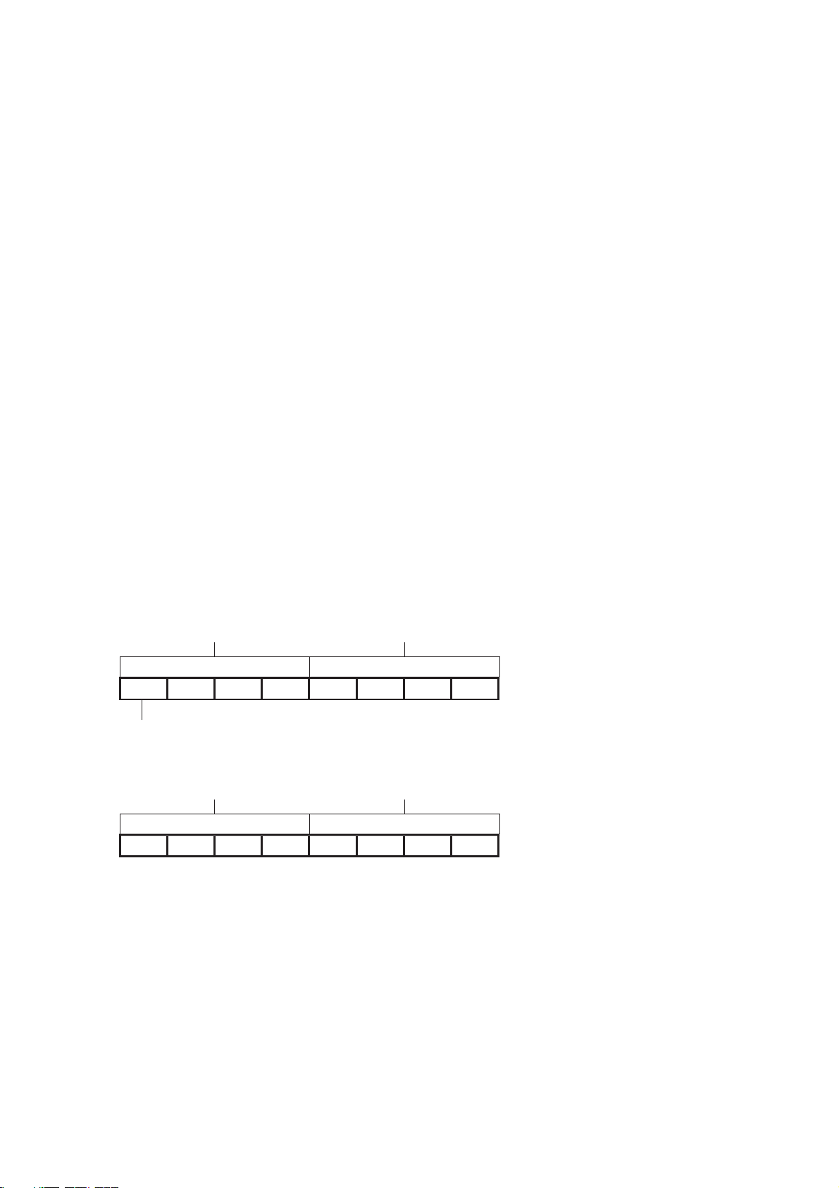
All through this manual where a double word is defined as for instance “n+2, n+3” this must be interpreted
as follows:
n+3 (MSW) n+2 (LSW)
sign x106x105x104x103x102x101x100 :BCD Double Word
0 = + (positive)
F = - (negative)
n+3 (MSW) n+2 (LSW)
x167x166x165x164x163x162x161x160 :Hexadecimal Double Word
LSW = Least Significant Word
MSW = Most Significant word
!WARNING Failure to read and understand the information provided in this manual may
result in personal injury or death, damage to the product, or product failure.
Please read each section in its entirety and be sure you understand the information provided in the section and related sections before attempting any of the procedures or operations given.
vii
Page 9

viii
Page 10

PRECAUTIONS
This section provides general precautions for using the Programmable Controller (PLC) and the Counter Unit.
The information contained in this section is important for the safe and reliable application of the Counter Unit. You
must read this section and understand the information contained before attempting to set up or operate a Counter
Unit and PLC system.
1 Intended Audience . . . . . . . . . . . . . . . . . . . . . . . . . . . . . . . . . . . . . . . . . . . . . x
2 General Precautions . . . . . . . . . . . . . . . . . . . . . . . . . . . . . . . . . . . . . . . . . . . . x
3 Safety Precautions. . . . . . . . . . . . . . . . . . . . . . . . . . . . . . . . . . . . . . . . . . . . . . x
4 Operating Environment Precautions. . . . . . . . . . . . . . . . . . . . . . . . . . . . . . . . xi
5 Application Precautions . . . . . . . . . . . . . . . . . . . . . . . . . . . . . . . . . . . . . . . . . xii
6 EC Directives . . . . . . . . . . . . . . . . . . . . . . . . . . . . . . . . . . . . . . . . . . . . . . . . . xv
ix
Page 11

Intended Audience 1
1 Intended Audience
This manual is intended for the following personnel, who must also have knowledge of electrical systems (an electrical engineer or the equivalent).
• Personnel in charge of installing FA systems.
• Personnel in charge of designing FA systems.
• Personnel in charge of managing FA systems and facilities.
2 General Precautions
The user must operate the product according to the performance specifications
described in the operation manuals.
Before using the product under conditions which are not described in the manual
or applying the product to nuclear control systems, railroad systems, aviation systems, vehicles, combustion systems, medical equipment, amusement machines,
safety equipment, and other systems, machines, and equipment that may have a
serious influence on lives and property if used improperly, consult your OMRON
representative.
Make sure that the ratings and performance characteristics of the product are sufficient for the systems, machines, and equipment, and be sure to provide the systems, machines, and equipment with double safety mechanisms.
This manual provides information for installing and operating OMRON Counter
Units. Be sure to read this manual before operation and keep this manual close at
hand for reference during operation.
!WARNING It is extremely important that a PLC and all PLC Units be used for the specified
purpose and under the specified conditions, especially in applications that can
directly or indirectly affect human life. You must consult with your OMRON representative before applying a PLC system to the above mentioned applications.
3 Safety Precautions
!WARNING The CPU Unit refreshes I/O even when the program is stopped (i.e., even in
PROGRAM mode). Confirm safety thoroughly in advance before changing the
status of any part of memory allocated to I/O Units, Special I/O Units, or CPU
Bus Units. Any changes to the data allocated to any Unit may result in unexpected operation of the loads connected to the Unit. Any of the following operation may result in changes to memory status.
• Transferring I/O memory data from a Programming Device to the CPU Unit.
• Changing present values in memory with a Programming Device.
• Force-setting/-resetting bits with a Programming Device.
• Transferring I/O memory files from a Memory Card or EM file memory to the
CPU Unit.
• Transferring I/O memory from a host computer or from another PLC on a network.
x
Page 12

Operating Environment Precautions 4
!WARNING Do not attempt to take any Unit apart while the power is being supplied. Doing so
may result in electric shock.
!WARNING Do not touch any of the terminals or terminal blocks while the power is being
supplied. Doing so may result in electric shock.
!WARNING Do not attempt to disassemble, repair, or modify any Units. Any attempt to do so
may result in malfunction, fire, or electric shock.
!Caution Execute online edit only after confirming that no adverse effects will be caused
by extending the cycle time. Otherwise, the Input signals may not be readable.
!Caution Confirm safety at the destination node before transferring a program to another
node or changing contents of the I/O memory area. Doing either of these without
confirming safety may result in injury.
!Caution Tighten the screws on the terminal block of the AC Power Supply Unit to the
torque specified in the operation manual. Loose screws may result in burning or
malfunction.
4 Operating Environment Precautions
!Caution Do not operate the control system in the following locations:
• Locations subject to direct sunlight.
• Locations subject to temperatures or humidity outside the range specified in
the specifications.
• Locations subject to condensation as the result of severe changes in temperature.
• Locations subject to corrosive or flammable gases.
• Locations subject to dust (especially iron dust) or salts.
• Locations subject to exposure to water, oil, or chemicals.
• Locations subject to shock or vibration.
!Caution Take appropriate and sufficient countermeasures when installing systems in the
following locations:
• Locations subject to static electricity or other forms of noise.
• Locations subject to strong electromagnetic fields.
• Locations subject to possible exposure to radioactivity.
• Locations close to power supplies.
!Caution The operating environment of the PLC System can have a large effect on the lon-
gevity and reliability of the system. Improper operating environments can lead to
malfunction, failure, and other unforeseeable problems with the PLC System. Be
sure that the operating environment is within the specified conditions at installation and remains within the specified conditions during the life of the system.
xi
Page 13

Application Precautions 5
5 Application Precautions
Observe the following precautions when using the Counter Unit or the PLC.
!WARNING Failure to comply with the following precautions could lead to serious or possibly
fatal injury. Always follow these precautions.
• Always ground the system with 100 Ω or less when installing the system, to
protect against electrical shock.
• Always turn OFF the power supply to the PLC before attempting any of the
following. Performing any of the following with the power supply turned ON
may lead to electrical shock
• Mounting or removing any Units (e.g., I/O Units, CPU Unit, etc.) or memory
cassettes.
• Assembling any devices or racks.
• Connecting or disconnecting any connectors, cables or wiring.
• Setting DIP switch or rotary switches.
!Caution Failure to comply with the following precautions could lead to faulty operation of
the PLC or the system, or could damage the PLC or PLC Units. Always follow
these precautions.
• Fail-safe measures must be taken by the customer to ensure safety in the
event of incorrect, missing, or abnormal signals caused by broken signal
lines, momentary power interruptions, or other causes.
• Interlock circuits, limit circuits, and similar safety measures in external circuits (i.e., not in the Programmable Controller) must be provided by the customer.
• If the IOM Hold Bit is turned ON, the outputs from the PLC will not be turned
OFF and will maintain their previous status when the PLC is switched from
RUN or MONITOR mode to PROGRAM mode. Make sure that the external
loads will not produce dangerous conditions when this occurs. (When operation stops for a fatal error, including those produced with the FALS instruction, all outputs from Output Unit will be turned OFF and only the internal
output status will be maintained.)
• Use the Units only with the power supplies and voltages specified in the
operation manuals. Other power supplies and voltages may damage the
Units.
• Take appropriate measures to ensure that the specified power with the rated
voltage and frequency is supplied. Be particularly careful in places where the
power supply is unstable. An incorrect power supply may result in malfunction.
• Install external breakers and take other safety measures against short-circuiting in external wiring. Insufficient safety measures against short-circuiting
may result in burning.
• Do not apply voltages to Input sections in excess of the rated Input voltage.
Excess voltages may result in burning.
• Do not apply voltages or connect loads in excess of the maximum switching
capacity to output sections. Excess voltage or loads may result in burning.
xii
Page 14

Application Precautions 5
!Caution • Install the Units properly as specified in the operation manuals. Improper
installation of the Units may result in malfunction.
• Be sure that all the mounting screws, terminal screws, and cable connector
screws are tightened to the torque specified in the relevant manuals. Incorrect
tightening torque may result in malfunction.
• Leave the label attached to the Unit when wiring. Removing the label may result
in malfunction if foreign matter enters the Unit.
• Remove the label after the completion of wiring to ensure proper heat dissipation. Leaving the label attached may result in malfunction.
• Use crimp terminals for wiring. Do not connect bare stranded wires directly to
terminals. Connection of bare stranded wires may result in burning.
• Double-check all the wiring and the connectors before turning ON the power
supply. Incorrect wiring or bad connections may result in burning or malfunction.
• Be sure that the terminal blocks, Memory Units, expansion cables, and other
items with locking devices are properly locked into place. Improper locking may
result in malfunction.
• Check switch settings, the contents of the DM Area, and other preparations
before starting operation. Starting operation without the proper settings or data
may result in an unexpected operation.
• Check the user program for proper execution before actually running it on the
Unit. Not checking the program may result in an unexpected operation.
• Confirm that no adverse effect will occur in the system before attempting any of
the following. Not doing so may result in an unexpected operation.
• Changing the operating mode of the PLC.
• Force-setting/force-resetting any bit in memory.
• Changing the present value of any word or any set value in memory.
• Do not pull on the cables or bend the cables beyond their natural limit. Doing
either of these may break the cables.
• Do not place objects on top of the cables or other wiring lines. Doing so may
break the cables.
• When replacing parts, be sure to confirm that the rating of a new part is correct.
Not doing so may result in malfunction or burning.
• Before touching a Unit, be sure to first touch a grounded metallic object in order
to discharge any static built-up. Not doing so may result in malfunction or damage.
• Do not touch circuit boards or the components mounted to them with your bare
hands. There are sharp leads and other parts on the boards that may cause
injury if handled improperly.
• Provide proper shielding when installing in the following locations:
• Locations subject to static electricity or other sources of noise.
• Locations subject to strong electromagnetic fields.
• Locations subject to possible exposure to radiation.
• Locations near power supply lines.
• Do not attempt to take any Units apart, to repair any Units, or to modify any
Units in any way.
• After connecting Power Supply Units, CPU Units, I/O Units, Special I/O Units,
or CPU Bus Units together, secure the Units by sliding the sliders at the top and
bottom of the Units until they click into place. Correct operation may not be possible if the Units are not securely properly. Be sure to attach the end cover pro-
xiii
Page 15

Application Precautions 5
vided with the CPU Unit to the right most Unit. CJ-series PLCs will not operate
properly if the end cover is not attached.
xiv
Page 16

EC Directives Section
6 EC Directives
6-1 Applicable Directives
• EMC Directives
• Low Voltage Directive
6-2 Concepts
EMC Directives
OMRON devices that comply with EC Directives also conform to the related EMC
standards so that they can be more easily built into other devices or the overall
machine. The actual products have been checked for conformity to EMC standards (see the following note). Whether the products conform to the standards in
the system used by the customer, however, must be checked by the customer.
EMC-related performance of the OMRON devices that comply with EC Directives
will vary depending on the configuration, wiring, and other conditions of the equipment or control panel on which the OMRON devices are installed. The customer
must, therefore, perform the final check to confirm that devices and the overall
machine conform to EMC standards.
Note Applicable EMC (Electromagnetic Compatibility) standards are as follows:
EMS (Electromagnetic Susceptibility):EN61000-6-2
EMI (Electromagnetic Interference):EN61000-6-4
(Radiated emission: 10-m regulations)
Low Voltage Directive
Always ensure that devices operating at voltages of 50 to 1,000 VAC and 75 to
1,500 VDC meet the required safety standards for the PLC (EN61131-2).
6-3 Conformance to EC Directives
6-3-1 Applicable Directives
•EMC Directives
• Low voltage directive
6-3-2 Concepts
EMC Directives
OMRON Units complying with EC Directives also conform to related EMC standards making them easier to incorporate in other Units or machines. The actual
products have been checked for conformity to EMC standards. (See the following
note.) Whether the products conform to the standards in the system used by the
customer, however, must be checked by the customer.
EMC-related performance of OMRON Units complying with EC Directives will
vary depending on the configuration, wiring, and other conditions of the equipment or control panel in which OMRON devices are installed. The customer
must, therefore, perform final checks to confirm that units and the overall system
conforms to EMC standards.
xv
Page 17

EC Directives Section
Note Applicable EMS (Electromagnetic Susceptibility) and EMI (Electromagnetic Inter-
ference standards in the EMC (Electromagnetic Compatibility) standards are as
follows:
Unit EMS EMI
CJ1W-CTL41-E EN 61000-6-2:2001 EN 61000-6-4:2001
6-3-3 Conformance to EC Directives
Units that meet EC directives also meet the common emission standard
(EN61000-6-4). The measures necessary to ensure that the standard is met will
vary with the overall configuration. You must therefore confirm that EC directives
are met for the overall configuration, particularly any radiated emission requirement (10 m).
xvi
Page 18

SECTION 1
Introduction
This section gives specifications of the CJ1W-CTL41-E and a brief description of the functions and features of the Unit and
the areas of application.
1-1 Features and Functions . . . . . . . . . . . . . . . . . . . . . . . . . . . . . . . . . . . . . . . . . . . . . . . . . . . . . . . . . . . . . . . 2
1-2 Basic Configuration . . . . . . . . . . . . . . . . . . . . . . . . . . . . . . . . . . . . . . . . . . . . . . . . . . . . . . . . . . . . . . . . . 4
1-3 Specifications and Characteristics . . . . . . . . . . . . . . . . . . . . . . . . . . . . . . . . . . . . . . . . . . . . . . . . . . . . . . 5
1-3-1 General Specifications . . . . . . . . . . . . . . . . . . . . . . . . . . . . . . . . . . . . . . . . . . . . . . . . . . . . . . . . 5
1-3-2 Functional Specifications . . . . . . . . . . . . . . . . . . . . . . . . . . . . . . . . . . . . . . . . . . . . . . . . . . . . . . 6
1-3-3 Input Specifications . . . . . . . . . . . . . . . . . . . . . . . . . . . . . . . . . . . . . . . . . . . . . . . . . . . . . . . . . . 7
1-4 Quick Start Up Reference Guide . . . . . . . . . . . . . . . . . . . . . . . . . . . . . . . . . . . . . . . . . . . . . . . . . . . . . . . 9
1-4-1 Configuring the Counter Unit. . . . . . . . . . . . . . . . . . . . . . . . . . . . . . . . . . . . . . . . . . . . . . . . . . 10
1-5 Operating Procedure Guidelines. . . . . . . . . . . . . . . . . . . . . . . . . . . . . . . . . . . . . . . . . . . . . . . . . . . . . . . 11
1-6 Application Areas . . . . . . . . . . . . . . . . . . . . . . . . . . . . . . . . . . . . . . . . . . . . . . . . . . . . . . . . . . . . . . . . . . 13
1
Page 19
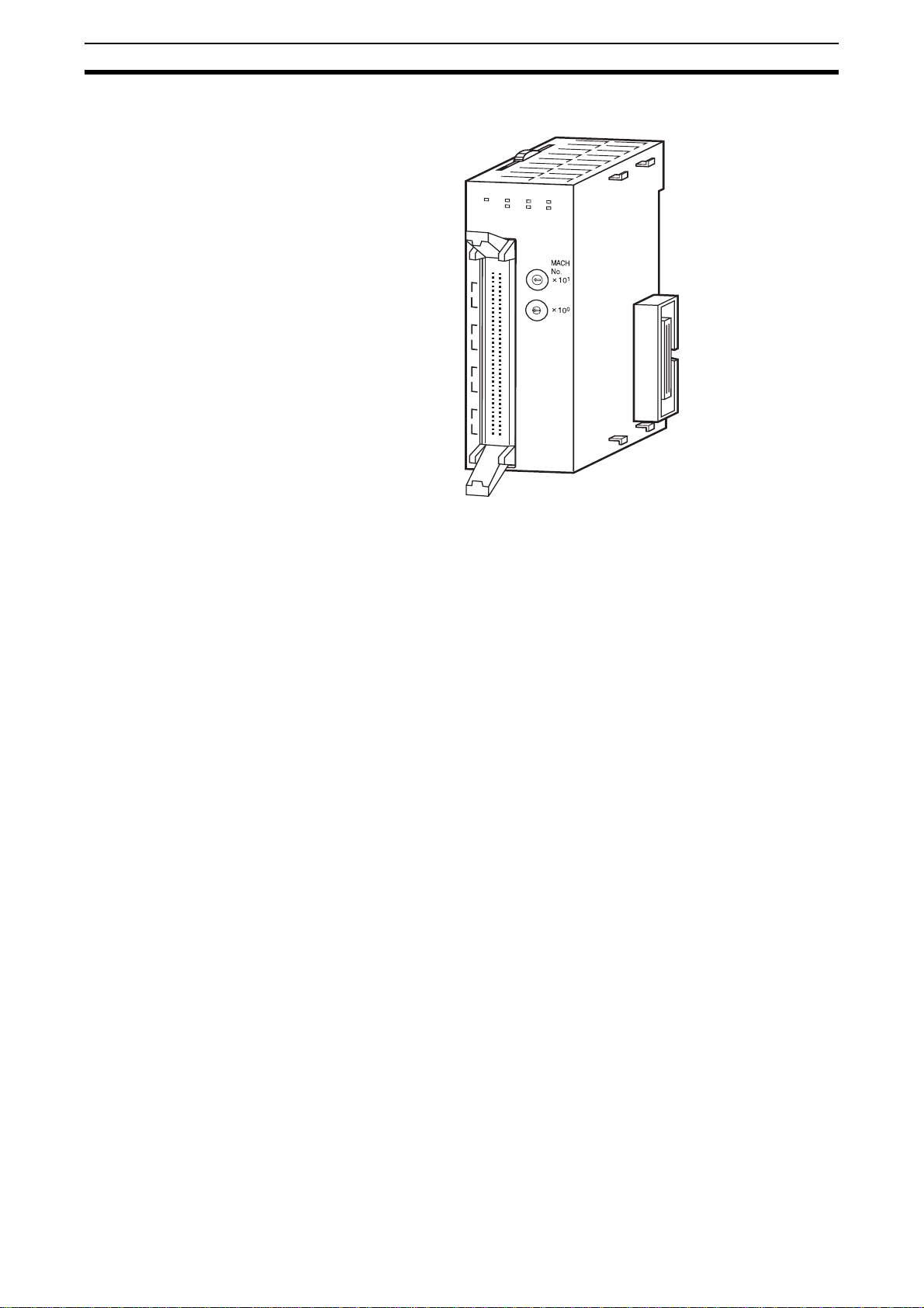
Features and Functions
1-1 Features and Functions
CTL41
RUN
C
H4
CH
3
CH
2
C
H
1
ERC
ERH
CH1
CH2
Section 1-1
CH3
CH4
3
4
2
5
1
6
0
7
9
8
3
4
2
5
1
6
0
7
9
8
CJ1W-CTL41-E The CJ1W-CTL41-E, a Special I/O Unit for CJ-series PLC-systems, is a freely
configurable Counter Unit. Depending on the requirements of your application, the specific behaviour of the Unit can be adjusted by changing the configuration settings.
CJ1W-CTL41-E Counters The CJ1W-CTL41-E Counter Unit is equipped with 4 Counters and counts
over a maximum binary range of 32-bits. Accepting input pulse frequencies of
up to 100 kHz allows precise control of fast motions. The Unit’s bi-directional
counting ability allows movement detecting in either direction. Each Counter
of the Unit can be configured independently. The Unit is equipped with 32
Software Outputs, each of which can be linked to Counter events. The Unit
can generate interrupts to the PLC CPU, to allow immediate CPU action upon
Counter events.
Counter Type Configuring the Unit starts with choosing one out of two Counter Types:
• Circular Counter (refer to section 3-2-1 Circular Counter)
• Linear Counter (refer to section 3-2-2 Linear Counter)
By default each Counter is set to Circular Counter. For all Counter Types the
full counting range is available. Circular and Linear Counters can be fully (DM) configured according to the application that is to be controlled.
Input Signal Type Depending on the type of input signal your application requires, every Counter
allows a choice out of three input signal types:
• Phase Differential Inputs (multiplication by either 1, 2 or 4)
(refer to section 3-3-1 Phase Differential)
• Up/Down Pulse Inputs (refer to section 3-3-2 Up & Down)
• Pulse & Direction Inputs (refer to section 3-3-3 Pulse & Direction)
Output Control Modes To control the Software Outputs the Unit can be configured in one of the two
following Output Control Modes:
• Range Mode (refer to section 3-5-1 Range Mode)
• Comparison Mode (refer to section 3-5-2 Comparison Mode)
In Range Mode, a configurable number of up to 4 Ranges can be applied to
individual Counters. Every Range can control up to a maximum of 32 Soft-
2
Page 20

Features and Functions
ware Outputs. An Output is turned ON when the Counter is in the corresponding Range.
In Comparison Mode a configurable number of up to 8 Comparison Values
can be applied to individual Counters. Depending on the direction of counting,
an Output can be set or reset (configurable) on reaching the Comparison
Value. Every Comparison Value can control up to maximum 32 Outputs.
Resetting Counter Value Resetting of the Counter Value can be configured depending on the applica-
tion needs. The following sources can trigger a reset:
• CIO bit in the PLC
• Z-Input
To enable resetting a Counter Value, the Software Enable Reset bit can be used
(refer to section 3-6 Reset Signals).
Hysteresis For Counters in Range Mode a hysteresis can be configured [1 to 255
counts], to prevent Outputs from toggling due to unwanted oscillating of
encoding equipment (e.g. rotary incremental encoder). Refer to section 3-7-1
Hysteresis.
Noise Filtering For the purpose of suppressing noise on the signal lines A, B of every
Counter, noise filters are provided. The cut-off frequencies for all signal lines
A and B are fixed to 100 kHz.
Section 1-1
Run-time Configurable Configuration settings of the Unit can be changed at Run-time by using the
IOWR-instruction to be able to quickly adjust to changing application needs
without the need of restarting the Unit or stopping the Counters. Care, however, must be taken when changing configuration settings. Refer to section 3-
5 Output Control for information.
Interrupt Support All Outputs can be configured to generate interrupts to the PLC. Generating
interrupts is only possible when the Counter Unit is mounted in a CPU-rack.
Support Software The Unit can be configured by using CX-Programmer Support Software or a
Programming Console.
Quick Start Up Reference
Guide
For a quick overview of all the features and functions the Counter Unit offers,
refer to section 1-4 Quick Start Up Reference Guide. This section also contains references to the particular section(s) in the Manual where more detailed
information about specific features and functions of the Counter Unit can be
found.
3
Page 21
Basic Configuration
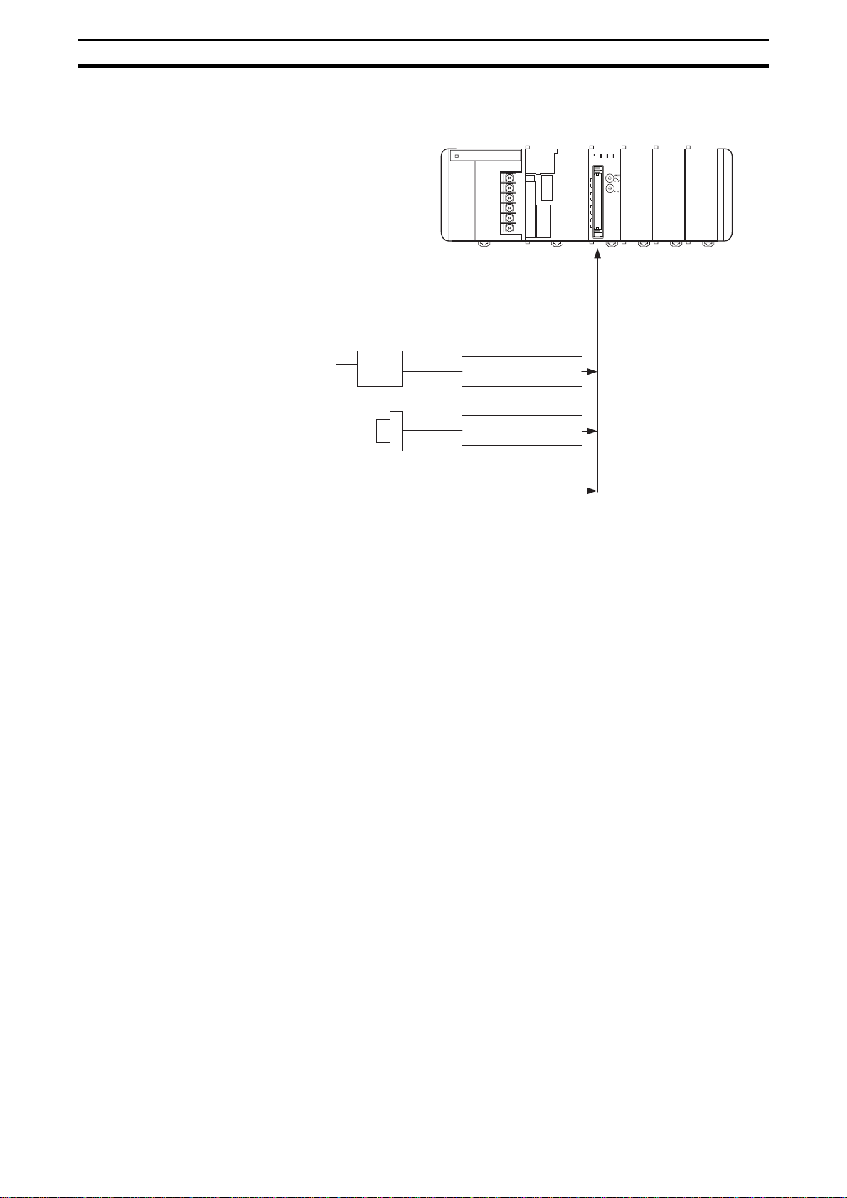
1-2 Basic Configuration
Typical applicable Pulse Generators for
Counter Inputs
Incremental Encoder
Proximity Sensor
CTL41
RUN CH1
CH4
CH3
CH2
CH1
Section 1-2
CH3
ERC
CH2
CH4
ERH
3
4
2
5
1
6
0
7
9
8
3
4
2
5
1
6
0
7
9
8
Other Pulse
Generators
Mounting Restrictions The CJ1W-CTL41-E Counter Unit is a Special I/O Unit belonging to the CJ
Series. A CJ1W-CTL41-E Counter Unit can be mounted to either a CJ CPU
Rack or CJ Expansion Rack.
Note 1. In case of a CJ1-H CPU Unit, the Counter Unit must be in one of the five
positions immediately to the right of the CJ1-H CPU Unit on the CPU Rack,
in order to allow the CJ1W-CTL41-E Counter Unit to generate interrupts
which activate interrupt tasks in a CJ1-H CPU Unit.
2. In case of a CJ1M CPU Unit, the Counter Unit must be in one of the three
positions immediately to the right of the CJ1M CPU Unit on the CPU Rack,
in order to allow the CJ1W-CTL41-E Counter Unit to generate interrupts
which activate interrupt tasks in a CJ1M CPU Unit
3. No interrupt tasks can be activated in CJ1-H or CJ1M CPU Units if the
CJ1W-CTL41-E Counter Unit is in any other position (i.e., 6th Unit position
or further away from the CJ1-H CPU Unit, or 4th Unit position or further
away from the CJ1M CPU Unit), or if it is on a CJ-series Expansion Rack.
Maximum Number of
CJ1W-CTL41-E Units
The maximum number of CJ1W-CTL41-E Counter Units which can be
mounted to a CJ CPU Rack or CJ Expansion Rack is equal to the number of
slots of the Rack. In a configuration with multiple Racks the maximum number
of CJ1W-CTL41-E Counter Units is limited to 24.
Furthermore, the number of Counter Units that can be mounted to one Rack
(i.e., a CPU Rack or Expansion Rack) depends on the maximum supply current from the Power Supply Unit that supplies the Rack and the current consumption of other Units on the Rack.
I/O Connection Methods To connect the Input signal wires to the Unit two methods are available:
4
Page 22

Specifications and Characteristics
• Directly connecting the wires by soldering them to the external connector.
• Indirectly connecting the wires by connecting them to screwless terminals
on an XW2G-40G7-E Input Terminal Block Unit. This Input Terminal Block
Unit allows connection of Line Driver or 24 V Encoder signals. The
XW2G-40G7-E is connected to the Unit via standard available OMRON I/
O-cables (XW2Z-xxxK).
• Indirectly connecting the wires by connecting them to screw terminals on
a standard XW2B-40G4, XW2B-40G5 or XW2D-40G6 OMRON Terminal
Block Unit, i.e. the Terminal Block Unit is connected to the Unit via standard available OMRON I/O-cables (XW2Z-xxxK).
Refer to section 2-3-2 Connector Wiring Methods for more details.
1-3 Specifications and Characteristics
1-3-1 General Specifications
Item CJ1W-CTL41-E
Unit type CJ-series Special I/O Unit
General Specifications Conform to general specifications for SYSMAC CJ-series
Operating Temperature 0 to 55 ° C
Storage Temperature -20 to 70 ° C
Humidity 10% to 90% without condensation
Internal Current Consumption 320 mA (at 5 V)
Dimensions (mm) 31 x 90 x 65 (W x H x D)
Weight 100 g
Mounting Position CJ-series CPU Rack or CJ-series Expansion Rack
Maximum Number of CTL41-E
Units per Rack
Maximum Number of CTL41-E
Units per basic CJ PLC
Data Exchange with CPU Unit • I/O Refresh Data Area: CIO-words 2000 to 2959. See Note 2.
Equal to the number of slots of the Rack (see Note 1)
24
• Special I/O Unit DM-Area: D-words 20000 to 29599: 90 DM-words per Unit are
transmitted from the CPU to the Unit at Power Up or when the Unit is restarted.
See Note 3.
Section 1-3
Note 1. The maximum number of Units per Rack also depends on the maximum
supply current of the Power Supply Unit and the current consumption of
other Units on the Rack.
2. The CJ1W-CTL41-E Special I/O Unit allocates space for 33 words in the
Special I/O Unit (CIO) Area (refer to section 4-2-3 CIO-Memory Mapping).
3. For a CJ1W-CTL41-E Special I/O Unit the same space as for 4 Units in the
Special I/O Unit DM Area are reserved. However, only the first 90 words
are used to make the DM-settings. The remaining 310 words can be used
as work-words (refer to section 4-2-4 DM-Memory Mapping).
5
Page 23

Specifications and Characteristics
Section 1-3
1-3-2 Functional Specifications
Item CJ1W-CTL41-E
Number of Counters 4
Counter Type • Circular Counter (refer to section 3-2-1 Circular Counter)
• Linear Counter (refer to section 3-2-2 Linear Counter)
The Counter Type can be selected using the appropriate DM bits (refer to section 4-2-4
DM-Memory Mapping).
Maximum Input Frequency 100 kHz, refer to section 1-3-3 Input Specifications for details
Signals per Counter Phase A, B and Z
Input Signal Types • Phase Differential (multiplication x1), (multiplication x2) and (multiplication x4) (refer to
section 3-3-1 Phase Differential)
• Up/Down (refer to section 3-3-2 Up & Down)
• Pulse & Direction (refer to section 3-3-3 Pulse & Direction)
Counter Control using CIOsoftware bits
Output Control Mode • Automatic Output Control in:
Reset Signals Every Counter can be reset to zero by (a combination of) the following sources:
Extra Functions • Hysteresis: To prevent Outputs from being switched On and Off by very small fluctua-
Noise Filtering Counter Inputs To suppress noise on the signal lines of the Counter Inputs (A, B) a fixed Noise Filter is
Initial Counter Value • The Initial Counter Value is transferred to the Unit when the Unit is Powered Up or
IORD- and IOWR-instructions Run-time configuration (See Note 2) and operation of the Counter Unit is possible by
Interrupts of Outputs The Soft Outputs of the Unit Output Pattern can all be configured to generate interrupts
Error History Log Function Stores up to 30 error log records (refer to section 5-2 Error codes)
• Open Gate / Start Counter: Counter is enabled to count pulses
• Close Gate / Stop Counter: Counter is disabled to count pulses
• Preset Counter: Preset Value can be set in CIO
• Reset Counter to zero
• Capture Counter Value: Captured Counter Value can be read using IORD-instruction
(refer to section 4-5-3-1 Captured Counter Value)
• Range Mode (Refer to section 3-5-1 Range Mode)
• Comparison Mode (Refer to section 3-5-2 Comparison Mode)
• Software Counter Reset Bit
• Z-Input
Refer to section 3-6 Reset Signals.
tions in the Counter Value around Range Limits, for every Counter an Hysteresisvalue [1, 255] can be defined (the Unit must in Range Mode). Refer to section 3-7-1
Hysteresis.
provided:
• Counter Inputs A and B: 100 kHz
Restarted. The Initial Counter Value is very useful to overcome problems in case of
power failure. Refer to section 3-7-2 Initial Counter Value.
using IORD- and IOWR-instructions. The following data can be read or written:
• DM-configuration data (refer to section 4-5-1 DM-data).
• Range- and Comparison Data (refer to section 4-5-2 Range- and Comparison data).
• Captured Counter Value (refer to section 4-5-3-1 Captured Counter Value)
• Counter Value (refer to section 4-5-3-2 Counter Value)
• (Re) Configure Counter Unit (refer to section 4-5-3-3 (Re) Configure Unit).
• Error Clear (refer to section 4-5-3-4 Error Clear Command)
to the CJ1-H/CJ1M CPU Unit. Refer to section 4-6-1 Outputs Generating Interrupts. See
also Note 1.
Note 1. A CJ1G-CPU@@H, CJ1H-CPU@@H or CJ1M-CPU@@ CPU Unit must be
used. The older CJ1G-CPU@@ CPU Units (without H suffix) do not support external interrupt tasks. To activate external interrupt tasks in a CJ1GH/ CJ1H-H CPU Unit, the CJ1W-CTL41-E Counter Unit must be in one of
6
Page 24
Specifications and Characteristics
Section 1-3
the five positions immediately to the right of the CPU Unit. For CJ1M CPU
Units, the CJ1W-CTL41-E Counter Unit must be in one of the three positions immediately to the right of the CJ1M CPU Unit. No external interrupt
tasks can be activated if the Unit is in any other position (i.e., 6th Unit position or further away from the CJ1-H CPU Unit, or 4th Unit position or further away from the CJ1M CPU Unit), or if it is on a CJ-series Expansion
Rack.
Power Supply Unit
CJ1-H or CJ1M CPU Unit
1st Unit
2ndUnit
3rd Unit
4th Unit
5th Unit
6thUnit
10th Unit
2. If an IOWR- or IORD-instruction is used during operation, comparison will
stop during instruction execution. Care must be taken, therefore, with the
timing of executing instructions. (Refer to section 3-5 Output Control for details.)
1-3-3 Input Specifications
Input Voltage Line Driver
Input Current
(typical)
Voltage levels Connectable to RS-422 compatible Line Drivers.
Note The Counter Inputs (A, B, Z) are insulated from each other. All Counter Inputs
are reverse polarity protected and insulated from the I/O-bus.
For CJ1-H CPU Units: External interrupt tasks can be
activated only from these Units.
For CJ1M CPU Units: External interrupt tasks can be
activated only from these Units.
Item Counter Inputs A, B and Z
11 mA
7
Page 25
Specifications and Characteristics
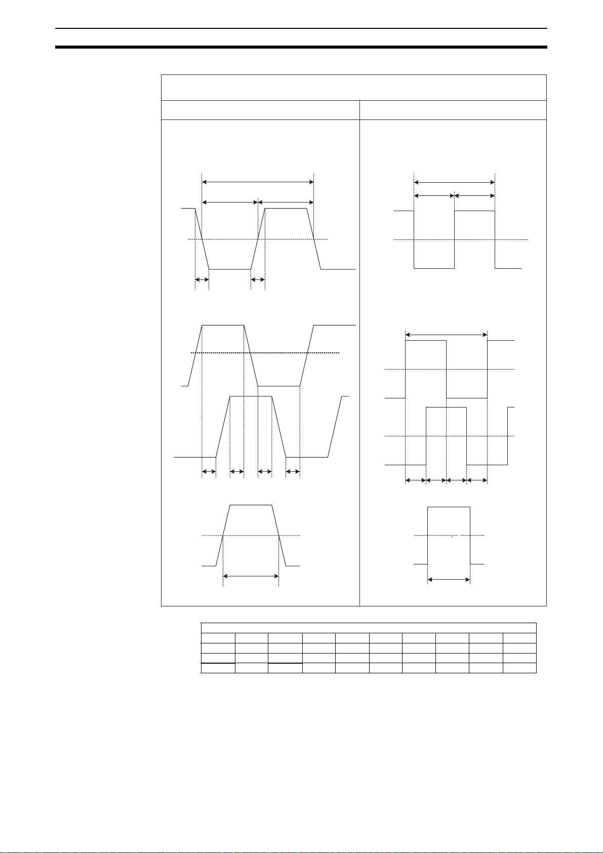
24V input signals (via Input Terminal Block) RS-422 Line Driver signals
Section 1-3
Counter Inputs A, B and Z
Counter inputs A and B
Input pulses with a duty factor of 50%
C
BB
On
50%
Off
AA
Relationship between A and B phases with phase
differential inputs
Phase A
On
50%
Off
Phase B
Counter inputs A and B
Input pulses with a duty factor of 50%
F
GG
On
0V
Off
Relationship between A and B phases with phase
differential inputs
On
0V
Off
Phase A
On
0V
Off
DDD
D
Counter Input Z *
On
50%
Off
Z
*Maximum allowed frequency of Z-pulses is 10 kHz *Maximum allowed frequency of Z-pulses is 10 kHz
E
Phase B
II
On
0V
Off
Z
Counter Input Z *
I
J
I
Timing requirement [µs]
JIHGFEDCBA
<3
>50<3
>10<3
>2
>100
>20
>4
>1
>10>4.5
>10
>20
>2
>50>100>10>23
>10
>1
>100
>20
>4
>23
>4.5
>10
>10
>10>1
Note As a general guideline it can be stated that if you want the timing requirements
for the Counter Inputs to satisfy the above mentioned specifications, you must
pay attention to the type of output driver of the encoder being used, the length
of the encoder cable and the frequency of the count pulses generated. For
8
Page 26

Quick Start Up Reference Guide
example, if you use an Open Collector encoder (e.g. E6B2-CWZ6C) at 24 V
with 10 m cable, you can typically generate count pulses up to 20 kHz. Therefore,
if you want to generate count pulses with higher frequencies, you should use a
different type of encoder (e.g. E6B2-CWZ1X with Line Driver output or a fast
push-pull 24 V encoder, e.g. E6C2-CWZ5GH) or reduce the length of the
encoder cable.
1-4 Quick Start Up Reference Guide
Section 1-4
Operation and
Configuration
Counter Inputs
1
(A, B, Z
Each individual Counter of the Counter Unit can be configured as Circular or
Linear Counter (refer to section the section 1-5 Operating Procedure Guide-
lines for quick start up information).
The diagram below shows the functions the Unit has available to operate and
configure the Unit (refer to SECTION 3 Operation and Configuration). The
numbers in grey refer to section the table on page 16.
Capture
2 2
Register
Circular
Linear
Counter
Preset
Register
Automatic
3
Output Control
5
Hysteresis
Outputs
8
Counter
2, 4 2, 4
Start/Stop
Counter
Reset
Exchanging data with CPU The diagram below shows the functions the Unit provides to exchange data
with the CPU (refer to section SECTION 4 Exchanging Data with CPU).
CJ-series CPU Unit
7
7
8
IOWR
IORD
Interrupts
CJ1W-CTL41-E
Unit Output Pattern
9
Page 27
Quick Start Up Reference Guide
Section 1-4
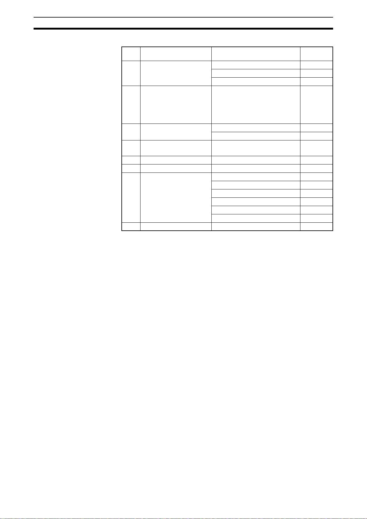
Ref Item Circular/Linear Counter Reference
1 Input Signal types Phase Differential (x1, x2, x4) 3-3-1
Up & Down 3-3-2
Pulse & Direction 3-3-3
2 Counter control • Open Gate / Start Counter
• Close Gate / Stop Counter
• Preset Counter
• Reset Counter
• Capture Counter Value
3 Output control • Range Mode 3-5-1
• Comparison Mode 3-5-2
4 Counter reset • Software Reset Bit
• Z-signal
5 Hysteresis Yes 3-7-1
6 Initial counter values Yes 3-7-2
7 Supported IORD / IOWR-
instructions
8 Interrupts of Outputs Yes 4-6-1
Captured Counter Value 4-5-3-1
Counter Value 4-5-3-2
Error Clear 4-5-3-4
DM-data 4-5-1
Range- and Comparison Data 4-5-2
(Re) Configure Unit 4-5-3-3
section
3-4
3-6
1-4-1 Configuring the Counter Unit
Configuring the Counter
Type
Configuring the Input
Type
Configuring the Output
Mode
Indirect Addressing for
Circular and Linear
Counters
Configuring each Counter starts with choosing the Counter Type, i.e. it must
be configured for Circular or Linear Counter (refer to section 3-2-1 Circular
Counter, section 3-2-2 Linear Counter and section 1-5 Operating Procedure
Guidelines for details).
Next, the Input Type (Phase Differential, Up/Down, or Pulse & Direction) for
every Counter has to be defined. During operation of the Counter, the Counter
can be Started, Stopped, Reset, Captured or Preset by using the corresponding
bits in CIO.
In order to link the Units Software Outputs to Counter events, the Output Control Mode (Range or Comparison Mode) must be selected. Furthermore, an
additional Hysteresis mechanism is available to control the Outputs. Refer to
section 3-5 Output Control.
The CJ1W-CTL41-E Counter Unit allocates 90 DM-words in the Special I/O
Unit DM-Area and a block of 34 CIO-words in the Special I/O Unit Area of the
PLC. The configuration of the Unit is done by making the appropriate DM-settings in the Special I/O Unit DM-Area allocated to the Unit.
The Special I/O Unit DM-Area is divided in an area of 10 words to make the
General Unit Settings and 4 blocks of 20 DM-words each to make the Counter
Specific Settings, which are unique for every Counter.
10
Page 28
Operating Procedure Guidelines
Depending on the Output Control Mode, Counter Range or Comparison Data
can be set. For each Counter, up to a maximum of 4 Ranges or 8 Comparison
Values can be assigned. You can set the Range or Comparison Data in a part
of DM or EM which is not being used. If you only intend to use a limited number of Ranges or Comparison Values then it is also possible to use the workwords of the Special I/O Unit DM-Area to store the Range or Comparison
Data (287 work-words for the CJ1W-CTL41-E are available). Therefore, at the
end of every block with Counter Specific Settings, you can specify an Indirect
Address. This Indirect Address points to the actual memory location where
the Range- or Comparison Settings of that specific Counter are stored.
For a detailed description about the CIO- and DM-Memory Allocation refer to
section 4-2 Memory Allocation.
Note During operation of the Unit, for Circular and Linear Counters run-time config-
uration is possible by using the IOWR-instruction from the PLC Ladder Program (refer to section 4-5 Supported IOWR/IORD-Instructions). Additionally,
Outputs can be configured to generate interrupts to the PLC by setting the
appropriate Interrupt Masks in DM. (refer to section 4-6 Interrupts)
Section 1-5
1-5 Operating Procedure Guidelines
In order to setup the Counter, follow the steps outlined below.
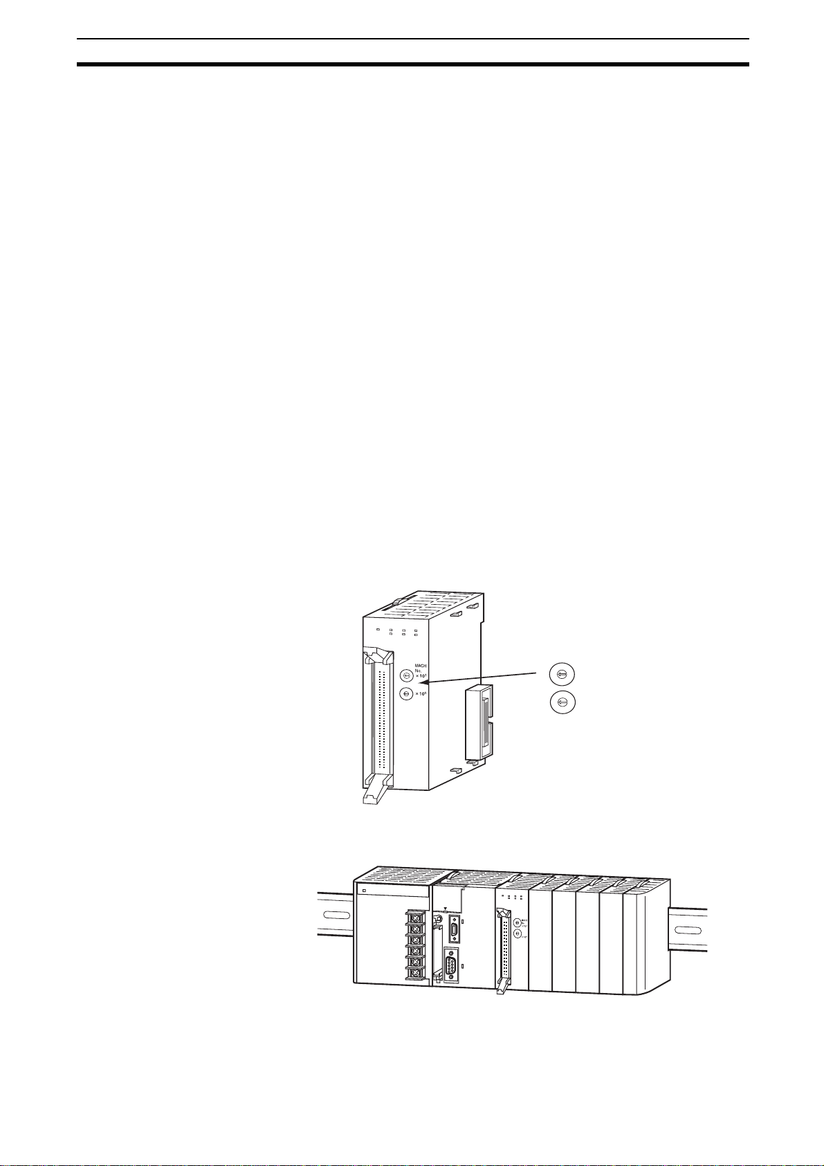
1, 2, 3… 1. Set the Machine Number to assign the start addresses of the allocated
CIO and DM areas. Refer to section 2-1-3 Machine Number Switch for further details.
CTL41
RUN
ERC
CH1
CH3
ERH
CH2
CH4
3
4
2
5
1
6
0
7
9
8
3
4
2
5
1
6
0
7
9
8
2. Install and wire the Unit. Refer to section 2-2 Installation and 2-3 Wiring for
further details.
Machine Number Switch:
3
MACH
2
4
1
5
0
6
No.
7
9
8
1
×
10
3
2
4
1
5
0
6
7
9
8
0
×
10
Set between 00 - 92
C
T
L
4
1
RUN
ERC
CH1
CH3
ERH
CH2
CH4
3
2
4
1
5
0
6
7
9
8
3
2
4
1
5
0
6
7
9
8
11
Page 29
Operating Procedure Guidelines
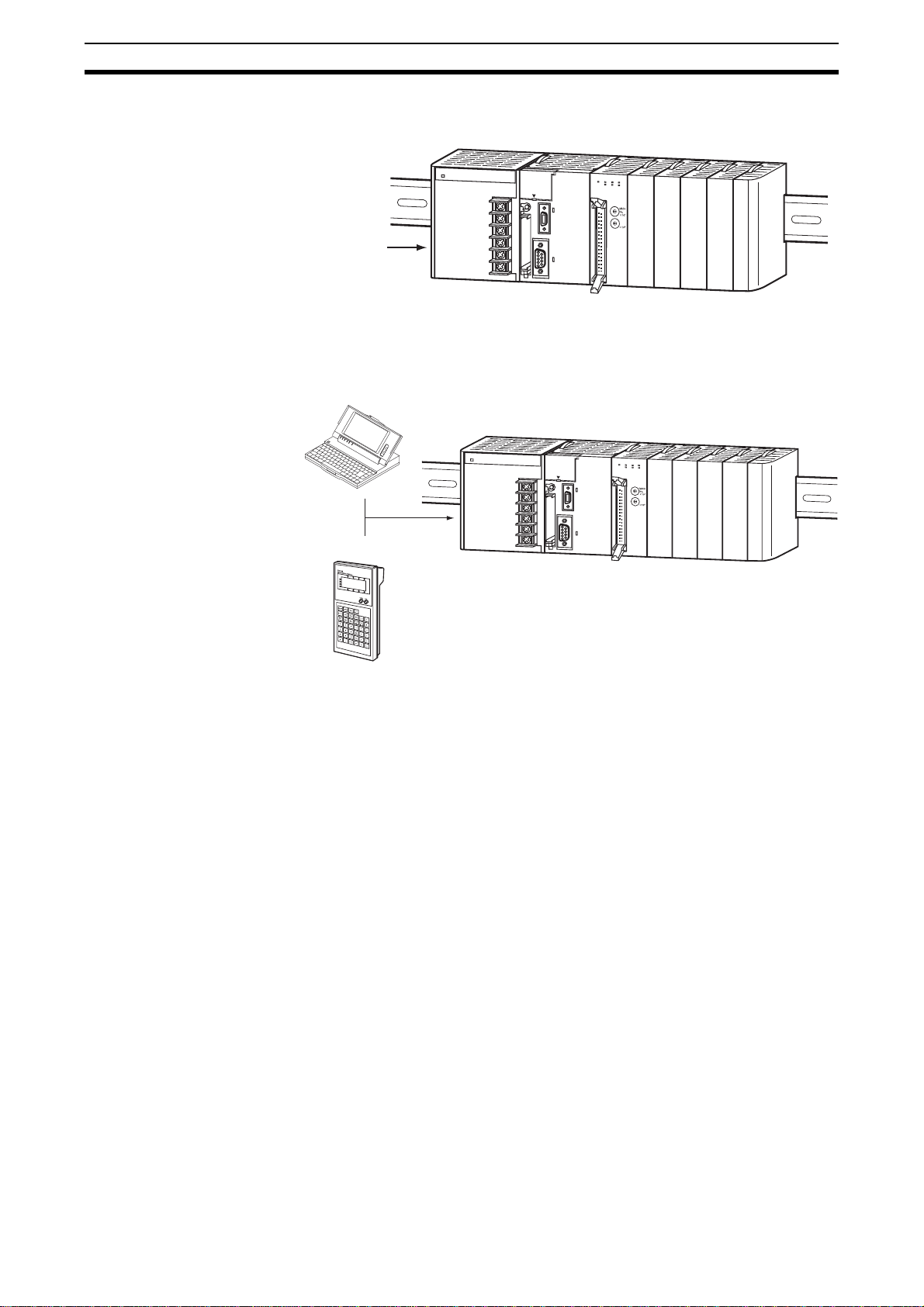
3. Turn ON the Power to the PLC.
Power ON
4. Create the I/O table. The I/O table can be created by using CX-Program-
CX-Programmer
CTL41
R
U
N
ER
C
H
C
1
C
H
3
ER
H
C
H
2
C
H
4
3
2
4
1
5
0
6
7
9
8
3
2
4
1
5
0
6
7
9
8
mer Support Software or a Programming Console.
CTL41
RUN
ERC
CH1
CH3
ERH
CH2
CH4
3
2
4
1
5
0
6
7
9
8
3
2
4
1
5
0
6
7
9
8
Section 1-5
Programming Console
Unit Configuration After the I/O table is created in step 4, you have to configure the Unit by mak-
ing the appropriate DM-settings. The Unit can be configured by using CX-Programmer Support Software or a Programming Console. Two Programming
Consoles can be used with the CJ-series CPU Units: the C200H-PRO27-E
and the CQM1-PRO01-E. The CS1W-KS001 Key Sheet must be used for
both.
1, 2, 3… 1. Every Counter can now be separately (DM-) configured. The configuration
of the Counter Type (Linear or Circular Counter) is done by DM-setting.
Refer to section SECTION 3 Operation and Configuration for detailed information about configuring the Unit.
2. Power up the PLC again or turn the Special I/O Unit Restart Bit to ON (to
transfer the DM-settings). All data related to Circular /Linear Counters is now
being exchanged between the PLC and the Unit in CIO-memory and available for usage in the Ladder Program.
3. Create and RUN a Ladder Program in the PLC. Refer to section SECTION
4 Exchanging Data with CPU for details on the interface between the CJseries Counter Unit and the CPU. Refer to section sections 6-2 to 6-5 for
application examples using Circular and Linear Counters.
12
Page 30

Application Areas
Refer to section 3-2-1 Circular Counter and 3-2-2 Linear Counter for more
details about both Counter Types. Refer to section 4-1-2 Special I/O Units
Restart bits for more information about restarting the Unit.
1-6 Application Areas
The main application areas of the Counter Unit are where signals with high
frequencies are counted and high-speed responses have to be triggered at
predefined Counter Values. Application areas include:
• Packaging and Sorting plants
• Dosing or proportioning plants
• Process Industry
Typical applications in which the CJ1W-CTL41-E can be used:
• (CAM)-Positioning
• Position Monitoring
• Length Measurement
• Flow Control
• Energy Measurement
Section 1-6
13
Page 31

Page 32

SECTION 2
Components, Installation and Wiring
This section provides details of the components, switch settings and other information required to install and operate
CJ1W-CTL41-E Counter Units.
2-1 Components and Switch Settings . . . . . . . . . . . . . . . . . . . . . . . . . . . . . . . . . . 16
2-1-1 Components . . . . . . . . . . . . . . . . . . . . . . . . . . . . . . . . . . . . . . . . . . . 16
2-1-2 Indicators . . . . . . . . . . . . . . . . . . . . . . . . . . . . . . . . . . . . . . . . . . . . . 16
2-1-3 Machine Number Switch . . . . . . . . . . . . . . . . . . . . . . . . . . . . . . . . . 17
2-2 Installation . . . . . . . . . . . . . . . . . . . . . . . . . . . . . . . . . . . . . . . . . . . . . . . . . . . 19
2-2-1 Installation Precautions . . . . . . . . . . . . . . . . . . . . . . . . . . . . . . . . . . 19
2-2-2 Installing Units . . . . . . . . . . . . . . . . . . . . . . . . . . . . . . . . . . . . . . . . . 19
2-3 Wiring . . . . . . . . . . . . . . . . . . . . . . . . . . . . . . . . . . . . . . . . . . . . . . . . . . . . . . . 21
2-3-1 Connector Pin-layout . . . . . . . . . . . . . . . . . . . . . . . . . . . . . . . . . . . . 21
2-3-2 Connector Wiring Methods . . . . . . . . . . . . . . . . . . . . . . . . . . . . . . . 22
2-3-3 Important Wiring Considerations . . . . . . . . . . . . . . . . . . . . . . . . . . . 23
2-3-4 Internal Circuitry . . . . . . . . . . . . . . . . . . . . . . . . . . . . . . . . . . . . . . . 24
2-3-5 Counter Input Configuration . . . . . . . . . . . . . . . . . . . . . . . . . . . . . . 24
15
Page 33

Components and Switch Settings Section 2-1
2-1 Components and Switch Settings
2-1-1 Components
Front and Side View
83.6
2.7
31
65
2-1-2 Indicators
90
2.7
CTL41
RUN
CH4
CH3
CH2
CH1
ERC
ERH
CH1
CH2
CH3
CH4
3
2
4
1
5
0
6
7
9
8
3
2
4
1
5
0
6
7
9
8
Indicators
Machine
Number Switch
Units in mm
16
CTL41
RUN
The indicators on the LED-display show the operating status of the Unit. The following table shows the meaning of the indicators.
LED Colour State Description
RUN Green ON Unit is in operation (i.e. Unit has initialised normally
ERC Red ON Unit has operational failure due to a detected error.
CH1
CH2
CH3
CH4
ERC
ERH
after (re-) starting the Unit).
OFF Unit is not in operation (i.e. Unit was not able to
initialise normally after (re-) starting the Unit or the
power to the Unit is switched OFF).
(For a list of all the errors that can cause an
operational failure, see 5-2 Error codes”.)
OFF Unit has no operational failure.
Page 34

Components and Switch Settings Section 2-1
LED Colour State Description
ERH Red ON CPU Unit has operational failure. (For a list of all the
errors that can occur at the CPU Unit see 5-1 Error
Indicators)
OFF CPU Unit has no operational failure.
CH1 Yellow ON Counter 1 is counting, i.e. the corresponding
counting gate is enabled and at least one pulse has
been detected.
OFF Counter 1 is not counting, i.e. the corresponding
counting gate is closed or no pulses have been
detected.
CH2 Yellow ON Counter 2 is counting, i.e. the corresponding
counting gate is enabled and at least one pulse has
been detected.
OFF Counter 2 is not counting, i.e. the corresponding
counting gate is closed or no pulses have been
detected.
CH3 Yellow ON Counter 3 is counting, i.e. the corresponding
counting gate is enabled and at least one pulse has
been detected.
OFF Counter 3 is not counting, i.e. the corresponding
counting gate is closed or no pulses have been
detected.
CH4 Yellow ON Counter 4 is counting, i.e. the corresponding
counting gate is enabled and at least one pulse has
been detected.
OFF Counter 4 is not counting, i.e. the corresponding
counting gate is closed or no pulses have been
detected.
2-1-3 Machine Number Switch
The CPU Unit and the Counter Unit exchange data via the Special I/O Unit Area
(CIO) and the Special I/O Unit DM Area. The Counter Unit is allocated 34 CIO
words and 90 DM words, starting at the addresses for this Machine number. The
Machine Number is set by using the two Machine Number rotary switches on the
front panel of the Unit.
As a result of this amount of allocated words, the subsequent 3 Machine Number
addresses cannot be used by other Special I/O Units, as their allocations would
overlap with this data.
Always turn OFF the power before setting the Machine Number. Use a flat-blade
screwdriver, being careful not to damage the switch. Be sure not to leave the
switch midway between settings.
3
2
4
1
5
0
6
7
9
8
3
2
4
1
5
0
6
7
9
8
17
Page 35

Components and Switch Settings Section 2-1
Note The Machine Number determines which words in the CPU Unit’s Special I/O Unit
Area (CIO 2000 to CIO 2959 and DM 20000 to DM 29599) are allocated to the
Counter Unit. The CJ1W-CTL41-E Unit occupies 4 Special I/O Unit Areas, i.e.
the next Special I/O Unit Machine Number must at least be set to this Unit’s
Machine Number plus 4. The Machine Number can only be set between 00 and
92. The Machine Numbers 93, 94 and 95 can not be set.
Switch
Setting
0 #0 CIO 2000 to CIO 2039 D20000 to D20399
1 #1 CIO 2010 to CIO 2049 D20100 to D20499
2 #2 CIO 2020 to CIO 2059 D20200 to D20599
3 #3 CIO 2030 to CIO 2069 D20300 to D20699
4 #4 CIO 2040 to CIO 2079 D20400 to D20799
5 #5 CIO 2050 to CIO 2089 D20500 to D20899
6 #6 CIO 2060 to CIO 2099 D20600 to D20999
7 #7 CIO 2070 to CIO 2109 D20700 to D21009
8 #8 CIO 2080 to CIO 2119 D20800 to D21199
9 #9 CIO 2090 to CIO 2129 D20900 to D21299
10 #10 CIO 2100 to CIO 2139 D21000 to D21399
…… … …
n #n CIO 2000 + (n * 10) to
…… … …
92 #92 CIO 2920 to CIO 2959 D29200 to D 29599
93 Cannot be set Not Applicable Not Applicable
94
95
Machine
Number
I/O Refresh Data Area
Addresses
CIO 2000 + (n * 10) + 39
Special I/O Unit DM Area
Addresses
D 20000 + (n * 100) to
D 20000 + (n * 100) + 399
Note 1. If two or more Special I/O Units are assigned the same Machine Number, a fatal
error “Unit No. Duplication Error” (in the PLC-CPU) will be generated (A40113
will turn ON) and the PLC will not operate.
2. The Counter Unit is allocated the words for 4 Units. If you use Special I/O Units
that are allocated more than 100 DM-words and 10 CIO-words, like the CJ1WCTL41-E Counter Unit, you should make sure that no memory overlapping
occurs. If the Machine Number for the Counter Unit is set to ‘n’ the Machine
Numbers 'n+1' through 'n+3' cannot be used on other units. In case two or more
Special I/O Units have set Machine Numbers causing an overlap of allocated
memory, a fatal error “Unit No. Duplication Error” (in the PLC-CPU) will be generated (A40113 will turn ON) and the PLC will not operate.
3. Besides the memory that is allocated to the Counter Unit in the Special I/O Unit
DM Area, for every Counter additional memory can be allocated in DM/EM.
This extra allocated amount of memory is used to make the Counter Specific
Settings related to Range or Comparison Mode. Memory is allocated by specifying an Indirect Address for every Counter in the Special I/O Unit DM Area.
For details about Indirect Addressing refer to section 4-2-2 Indirect Addressing.
18
Page 36

Installation Section 2-2
2-2 Installation
2-2-1 Installation Precautions
When installing the CJ1W-CTL41-E Counter Unit on the PLC system, observe
the following handling precautions
• Always turn OFF the power supply to the PLC before mounting or dismounting a Unit or connecting or disconnecting cables.
• Provide separate conduits or ducts for the I/O lines to prevent noise from
high-tension lines or power lines.
• Leave the label on top of the Unit attached when wiring. Removing the label
prior to wiring may result in malfunction if foreign matter enters the Unit.
• Remove the label after the completion of wiring to ensure proper heat dissipation. Leaving the label attached may result in malfunction.
Up to 24 Units can be connected for each PLC (CPU Unit), with a maximum of 10
on each Rack (CPU Rack and Expansion Racks).
Note The Unit must be mounted to one of the five positions immediately to the right of
the CJ1-H CPU Unit (when facing the PLC) to generate interrupts to the CPU
Unit to execute external interrupt tasks. Interrupts are not supported from any
other location on the CPU Rack and are not supported at all from Expansion
Rack. They are also not supported by CJ1G-CPU44 and -45, without ‘H’ suffix.
2-2-2 Installing Units
!Caution Be sure to turn OFF the power supply to the PLC before installing or removing
1, 2, 3… 1. Align the connectors and hooks accurately and press the Units together firmly
Units or connecting or disconnecting connectors.
Use the following procedure to install CJ1W-CTL41-E Counter Units. Connect the
Units before mounting them to DIN-rail.
when connecting them.
PA205R
Hook
PO
W
ER
L1
AC100-24
0V
INPUT
L2/N
RUN
OUTPUT
AC240V
DC24V
SYSMAC
CJ1G-CPU44
P
R
O
G
R
A
M
M
A
C
O
N
T
R
O
L
L
E
R
B
L
E
OPEN
M
CP
W
R
BUSY
PERIPHERAL
PORT
ERR/ALM
RUN
INH
PRPHL
COM
M
Connector
CTL41
RUN
1
1
B
ERC
CH1
ERH
CH2
1
1
Hook holes
CH3
CH4
3
4
2
5
1
6
0
7
9
8
3
4
2
5
1
6
0
7
9
8
19
Page 37

Installation Section 2-2
2. Slide the yellow sliders on the top and bottom of the Units until they click into
place, firmly locking the Units together.
Slide the sliders toward the back
until they click into place.
Slider
PA205R
POWER
AC100-240V
INPUT
OUTPUT
AC240V
DC24V
SYSMAC
CJ1G-CPU44
P
C
L1
L2/N
RUN
RUN
ERR/ALM
INH
R
O
G
R
A
MM
A
B
L
E
PRPHL
O
N
T
R
O
LLE
R
COMM
OPEN
M
C
P
W
R
B
U
S
Y
PERIPHE
RAL
PORT
CTL41
RUN
ERC
CH1
ERH
CH2
2
1
0
1
0
1
1
MODE
1
1
1
1
BA
B
A
CH3
CH4
Release
3
4
5
6
7
9
8
3
4
2
5
6
7
9
8
3. Attach an End Plate to the Unit on the right end of the Rack.
Note The Units may not function properly if the sliders are not locked into place.
Always connect the End Plate to the rightmost Unit. The CJ-series PLC will not
function properly without the End Plate connected. The End Plate is provided with
the CPU Unit.
Lock
20
Page 38

Wiring Section 2-3
2-3 Wiring
2-3-1 Connector Pin-layout
The 40-pin connector on the front of the Unit is divided in two rows, each row containing 20-pins as indicated in the figure below. The Counter Inputs of the Unit are
logically grouped together and allocated to the pins of the connector. The following
table lists the allocation of the external signals to the respective pins.
Pin No. Signal Pin No. Signal
40 Not Connected 39 Not Connected
PIN 40 PIN 39
CH4
CH3
CH2
CH1
PIN 2 PIN 1
38 37
36 Z- 35 Z+
34 B- 33 B+
32 A- 31 A+
Channel 4
30 Not Connected 29 Not Connected
28 27
26 Z- 25 Z+
24 B- 23 B+
22 A- 21 A+
Channel 3
20 Not Connected 19 Not Connected
18 17
16 Z- 15 Z+
14 B- 13 B+
12 A- 11 A+
Channel 2
10 Not Connected 9 Not Connected
8 7
6Z- 5Z+
4B- 3B+
2A- 1A+
Channel 1
Counter Inputs To the Counter Inputs of the Counter Unit signals can be applied originating from
one of the following driver types:
• RS-422 Line Driver, either directly connected to the connector on the front of
the Unit or through a separate Input Terminal Block, e.g. the OMRON XW2G40G7-E or XW2D-40G6.
• 24 Vdc signals from NPN- or PNP Drivers, only through the separate
OMRON XW2G-40G7-E Input Terminal Block.
21
Page 39

Wiring Section 2-3
2-3-2 Connector Wiring Methods
!Caution Be sure that all the connectors are wired correctly and properly connected to the
Counter Unit, to prevent the Unit from malfunctioning.
To wire the CJ1W-CTL41-E in order to connect the external signals three methods
are available:
1. Directly connecting the wires and cables to an external connector. Recommended connectors are 40-pin MIL-C-83503 (or DIN 41651 or IEC 60603-1)
compatible 40-pole connectors.
2. Indirectly connecting the wires and cables to the screw terminals of an XW2B40Gx Terminal Block Unit, which is connected to the Unit with a standard
XW2Z I/O cable. Both parts can be ordered separately.
3. Indirectly connecting the wires and cables to the screw-less terminals of an
XW2G-40G7-E Terminal Block Unit, which is connected to the Unit with a
standard XW2Z I/O cable. Both parts can be ordered separately.
The figures below show the XW2B-40Gx and XW2G-40G7-E Input Terminal
Blocks.
Terminal Block Unit
22
The following Terminal Block Units are recommended for using together with the
CJ1W-CTL41-E Counter Unit:
Item Description Input type supported
XW2B-40G4 40 screw terminals (M2.4) Line driver only
XW2B-40G5 40 screw terminals (M3.5) Line driver only
XW2D-40G6 40 screw terminals, compact Line driver only
XW2G-40G7-E 36 screwless terminals Line driver / 24 Vdc
Page 40

Wiring Section 2-3
These Terminal Block Units can be mounted to a DIN-rail or to a flat surface using
screws. The connector on front of the Unit must be connected to a Terminal Block
Unit through a standard (40 wire) cable. For this purpose you can use the standard
available cables with product-number XW2Z-xxxK. The length of the cable is indicated by ‘xxx’ in centimetres. The following cables are available:
• XW2Z-050K (0.5 m)
• XW2Z-100K (1 m)
• XW2Z-150K (1.5 m)
• XW2Z-200K (2 m)
• XW2Z-300K (3 m)
• XW2Z-500K (5 m)
The next figure shows how to use the Terminal Block Unit in a typical configuration
together with the CJ1W-CTL41-E Counter:
CTL41
RUN
ERC
CH1
CH3
ERH
CH2
CH1
3
4
2
5
1
6
0
7
9
8
3
4
2
5
1
6
0
7
9
8
2
Refer to section Appendix A Using Input Terminal Block Units for information on
the numbering of the screw-terminals. You need this information in case you want
to connect the external signals via Terminal Block Units to the Counter Unit.
2-3-3 Important Wiring Considerations
Use the following guidelines when planning the system wiring of the Unit:
• Disconnect the power to the PLC-system before wiring the Unit.
• Make sure the PLC-system is properly grounded.
• Use shielded, twisted pair cables and ground the shield when wiring the Coun-
ter Inputs (A, B, Z). When grounding the shield at the side of the Unit, use the
same reference as the ground terminal of the PLC-Power Supply is connected
to.
• Make the wiring for the Counter Inputs A, B and Z as short as possible and do
not route the wires parallel to lines that produce a lot of noise, such as high-voltage power lines.
• Use a separate stabilised Power Supply for the Counter Unit and another Power
Supply for other Units.
23
Page 41

Wiring Section 2-3
2-3-4 Internal Circuitry
Counter Input Circuitry
The figure below shows the internal input circuitry for all three input signals for
each of the four Counter channels.
Phase A
LD+
LD-
Phase B
LD+
LD-
2-3-5 Counter Input Configuration
The following example illustrates how to wire the Counter Inputs in a typical configuration according to the output-driver of the encoder or proximity switch being
used. In the example Counter channel 1 is used. The configuration shown here,
related to a specific output-driver, can also be referred to in case other pulse generating equipment with similar output-drivers is being used.
Phase Z
LD+
LD-
24
Page 42

Wiring Section 2-3
n
x
Line Driver (RS422)
CJ1W-CTL41-E Counter U
Terminals:
Encoder
Black: Phase A+
Black/red: Phase AWhite: Phase B+
White/red: Phase BOrange: Phase Z+
Orange/red: Phase Z-
1 (Phase A, LD+)
2 (Phase A, LD-)
3 (Phase B, LD+)
4 (Phase B, LD-)
5 (Phase Z, LD+)
6 (Phase Z, LD-)
Power Supply
. E6B2-CWZ1X
ne Driver outputs
A+
A-
B+
B-
Z+
Brown: 5 VDC
Blue: 0 V (COM)
Shielded twisted-pair cable
Counter 1
0 V
+5 V
5 VDC
Power Supply
CJ1W-CTL41-E Counter Unit
1
2
3
4
5
Z-
Encoder
6
Connector
25
Page 43

Page 44

SECTION 3
Operation and Configuration
This section describes how to configure the CJ1W-CTL41-E Counter Unit and how to operate the Unit according to the
specific requirements of your application.
3-1 Overview. . . . . . . . . . . . . . . . . . . . . . . . . . . . . . . . . . . . . . . . . . . . . . . . . . . . . 28
3-2 Counter Types . . . . . . . . . . . . . . . . . . . . . . . . . . . . . . . . . . . . . . . . . . . . . . . . . 29
3-2-1 Circular Counter . . . . . . . . . . . . . . . . . . . . . . . . . . . . . . . . . . . . . . . . 30
3-2-2 Linear Counter . . . . . . . . . . . . . . . . . . . . . . . . . . . . . . . . . . . . . . . . . 31
3-3 Input Signal Types . . . . . . . . . . . . . . . . . . . . . . . . . . . . . . . . . . . . . . . . . . . . . 33
3-3-1 Phase Differential . . . . . . . . . . . . . . . . . . . . . . . . . . . . . . . . . . . . . . . 33
3-3-2 Up & Down . . . . . . . . . . . . . . . . . . . . . . . . . . . . . . . . . . . . . . . . . . . 34
3-3-3 Pulse & Direction . . . . . . . . . . . . . . . . . . . . . . . . . . . . . . . . . . . . . . . 35
3-4 Controlling a Counter . . . . . . . . . . . . . . . . . . . . . . . . . . . . . . . . . . . . . . . . . . . 36
3-5 Output Control . . . . . . . . . . . . . . . . . . . . . . . . . . . . . . . . . . . . . . . . . . . . . . . . 38
3-5-1 Range Mode . . . . . . . . . . . . . . . . . . . . . . . . . . . . . . . . . . . . . . . . . . . 40
3-5-2 Comparison Mode . . . . . . . . . . . . . . . . . . . . . . . . . . . . . . . . . . . . . . 46
3-6 Reset Signals. . . . . . . . . . . . . . . . . . . . . . . . . . . . . . . . . . . . . . . . . . . . . . . . . . 53
3-7 Extra Functions . . . . . . . . . . . . . . . . . . . . . . . . . . . . . . . . . . . . . . . . . . . . . . . . 54
3-7-1 Hysteresis . . . . . . . . . . . . . . . . . . . . . . . . . . . . . . . . . . . . . . . . . . . . . 54
3-7-2 Initial Counter Value. . . . . . . . . . . . . . . . . . . . . . . . . . . . . . . . . . . . . 55
27
Page 45

Overview Section 3-1
3-1 Overview
After you have installed and wired the CJ1W-CTL41-E Counter Unit as described
in Section 2-2 Installation and Section 2-3 Wiring, you have to configure the Unit
by making DM-settings.
In this section you will learn how to configure the CJ1W-CTL41-E Counter Unit in
order to adjust the behaviour of the Unit according to the specific requirements of
your application (refer to section Section 1-4 Quick Start Up Reference Guide for
an overview of the configuration items for every Counter). Also throughout this
section, the CIO-words that are relevant to operate the Unit from the PLC ladder
program are mentioned (refer to section Section 4-2-3 CIO-Memory Mapping for
an overview). For an overview of all the DM-settings that can be made refer to section Section 4-2-4 DM-Memory Mapping.
All the features and functions that the Counter Unit offers are (DM-) configurable.
In the Special I/O Unit DM-area which is allocated to the Counter after the Unit has
been properly installed (see Section 1-5 Operating Procedure Guidelines), all the
available features and functions of the Unit are represented by their corresponding
DM-words. You are free to choose the sequence in which you configure the different functions. However, it is are recommended to follow the sequence of configuring the features and functions in the order as described in this section.
Note 1. Throughout this section for the DM- and CIO- addresses an offset is defined
with respect to the physical address of the first word of the block that is allocated to the Counter Unit (N = Machine Number):
• m = DM20000 + (Nx100), address of the first word of the block of 90 DMwords reserved for the Unit
• n = CIO2000 + (Nx10), address of the first word of the block of 34 CIO-words
reserved for the Unit
• Example: m+2 indicates the DM-word located at DM20000 +(Nx100) + 2.
2. Double words are indicated as for example “n+22, n+23” (double word in CIO)
or “m+57, m+58” (double word in DM). How to distinguish between the leastand most significant words (LSW and MSW) within double words, you should
refer to section the section called “About this Manual” at the beginning of this
Manual.
28
Page 46

Counter Types Section 3-2
3-2 Counter Types
Every single Counter of the Counter Unit can be set independently to one of the
following Counter Types:
• Circular Counter (refer to section Section 3-2-1 Circular Counter)
• Linear Counter (refer to section Section 3-2-2 Linear Counter)
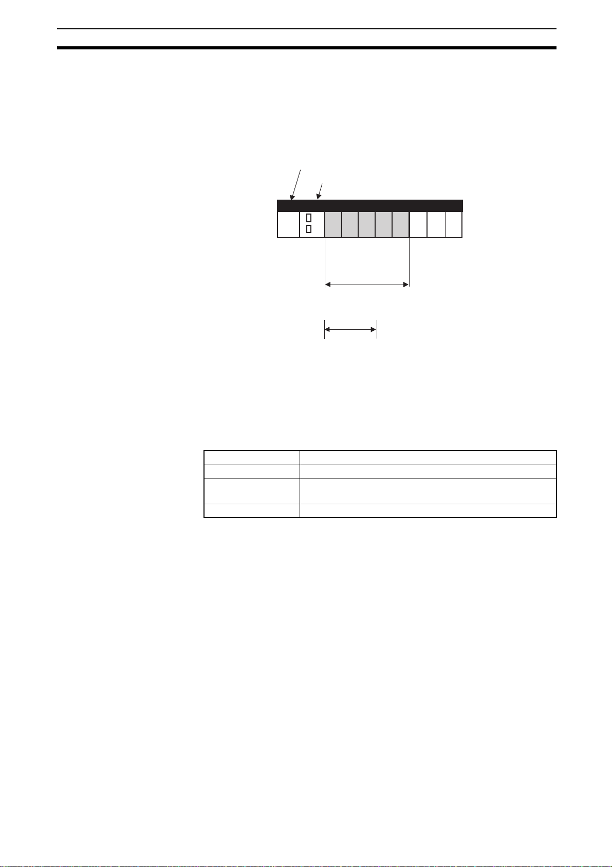
Each Counter can be configured Circular or Linear Counter by giving the corresponding word in DM the appropriate setting:
CNT1: CNT2:
m+10 m+30
CNT3: CNT4:
m+50 m+70
15 14 13 12 11 10 9 876543210
For Circular and Linear Counters all the functions and features of the Counter Unit
are available and configurable.
Counter Value For all Counter Types the 32-bit Counter Value is reflected in CIO.
CNT1: CNT2:
n+19 n+23
n+20 n+24
CNT3: CNT4:
n+27 n+31
n+28 n+32
15 14 13 12 11 10 9 876543210
Circular Counter: between 00000000H and FFFFFFFF
Linear Counter: between 80000000H and 7FFFFFFF
Counter Type:
0 = Circular Counter
1 = Linear Counter
Counter Value
H
H
29
Page 47

Counter Types Section 3-2
3-2-1 Circular Counter
Note All of the functions listed in Section 1-3-2 Functional Specifications can be used
if a Circular Counter is configured.
Configuring Circular Counters
CNT1: CNT2:
m+10 m+30
CNT3: CNT4:
m+50 m+70
15 14 13 12 11 10 9 876543210
Counter Type:
0 = Circular Counter
A Circular Counter has 32-bits (the full counting range) available to count up- or
downwards over the positive counting range between 0 and the Upper Count
Limit.
≤
1 Upper Count Limit 4,294,967,295
00000001 Upper Count Limit FFFFFFFF
≤
≤≤
Up
Counting
H
Rollover
0
(=00000000
)
H
Down
Counting
Configuring Upper Count
Limit
CNT1: CNT2:
m+13 m+33
m+14 m+34
CNT3: CNT4:
m+53 m+73
m+54 m+74
30
Counter Value
The Upper Count Limit can be configured between 1 and 4,294,967,295
(=FFFFFFFF
ble count limit of FFFFFFFF
). By default the Upper Count Limit is equal to the maximum possi-
H
.
H
For Circular Counters the Counter automatically rolls over to 0 if the Counter Value
exceeds the Upper Count Value and continues counting. If the Counter Value
goes below 0 the Counter rolls over to the Upper Count Value and continues
counting.
15 14 13 12 11 10 9 876543210
Upper Count Limit
Set Upper Count Limit for Circular Counters between 00000001H and FFFFFFFFH.
Per default (=00000000
) the Upper Count Limit is equal to FFFFFFFFH.
H
Page 48

Counter Types Section 3-2
3-2-2 Linear Counter
Note All of the functions listed in Section 1-3-2 Functional Specifications can be used
if a Linear Counter is configured.
Configuring Linear Counters
CNT1: CNT2:
m+10 m+30
CNT3: CNT4:
m+50 m+70
A Linear Counter has the full counting range (=32 bits) available to count up- or
downwards over the positive and negative counting range between the Minimum
Count Limit and the Maximum Count Limit. By default the Minimum and Maximum
Count Limits are set to the maximum counting limits (i.e. –2,147,483,648 and
+2,147,483,647 respectively).
−2,147,483,648 ≤ Lowercount Limit ≤ −1
80000000 ≤ Lowercount Limit ≤ FFFFFFFF
Underflow Overflow
If the Counter Value goes above the Upper Count Limit or below the Lower Count
Limit an Overflow- and Underflow flag will be set respectively. These are reported
in CIO for the corresponding Counter.
15 14 13 12 11 10 9 876543210
0
HH
00000001 Uppercount Limit 7FFFFFFF
≤
1 Uppercount Limit +2,147,483,647
Up Counting
Counter Value
Down Counting
Counter Type:
1 = Linear Counter
≤
≤≤
H
Configuring Upper and
Lower Count Limits
CNT1: CNT2:
m+13 m+33
m+14 m+34
m+15 m+35
m+16 m+36
CNT3: CNT4:
m+53 m+73
m+54 m+74
m+55 m+75
m+56 m+76
On occurrence of an Overflow or Underflow, every Counter can be configured to
report a corresponding error-code. You can use Overflow/Underflow Error-Code
Generation to store Overflow and underflow errors in the EEPROM inside the Unit
(refer to section Section 5-2-3 Overflow/Underflow errors).
The Upper Count Limit must be positive and the Lower Count Limit must be negative (zero is not allowed as Count Limit). To set the Maximum and Minimum
Count Limits refer to section the following:
15 14 13 12 11 10 9 876543210
Set Upper Count Limit for Linear Counters between 00000001H and 7FFFFFFFH. By default
(=00000000
Linear Counters between 80000000
Count Limit is equal to 80000000
) the Upper Count Limit is equal to 7FFFFFFFH. Set Lower Count Limit for
H
and FFFFFFFFH. By default (=00000000) the Lower
H
.
H
Upper Count Limit
Lower Count Limit
31
Page 49

Counter Types Section 3-2
Configuring Error-Code
Generation
CNT1: CNT2:
m+12 m32
CNT3: CNT4:
m+52 m+72
Reporting Overflow and
Underflow
CNT1: CNT2:
n+21 n+25
CNT3: CNT4:
n+29 n+33
To configure Overflow/Underflow Error Code Generation for a Linear Counter refer
to section the following:
15 14 13 12 11 10 9 876543210
Overflow/Underflow Error-Code
generation:
0 = No Error-Code generation
1 = Error-Code generation
An Overflow or Underflow of a Linear Counter is reported in the corresponding bits
in CIO.
15 14 13 12 11 10 9 876543210
Counter Overflow:
0 = No Overflow
1 = Overflow
Counter Underflow:
0 = No Underflow
1 = Underflow
32
Page 50

Input Signal Types Section 3-3
(
)
3-3 Input Signal Types
The type of input you require for your application is selected by means of four bits
in the Signal Type Word in DM. For every Counter the Signal Type can be selected
individually.
CNT1: CNT2:
m+11 m+31
CNT3: CNT4:
m+51 m+71
15 14 13 12 11 10 9 876543210
3-3-1 Phase Differential
Phase Differential Signals are connected to the inputs A, B and Z of every Counter. The count direction is determined by the phase angle between input A and
input B. If signal A leads to B, the counter increments. If signal B leads to A, the
counter decrements.
Incremental encoder
Signal Type:
0 = Phase Differential (multiplication x1)
1 = Phase Differential (multiplication x2)
2 = Phase Differential (multiplication x4)
4 = Up & down
8 = Pulse & Direction
Counter
A
B
Input A
Input B
Z
Reset Input
Input Z
Forward rotation (CW) Reverse rotation (CCW)
Phase A
Phase B
12 3
210
Multiplication x1
12 3
456
54 32 10
Multiplication x2
123456
789101112 11109876543210
Multiplication x4
Multiplication x1 By default the Counter is configured for Multiplication by 1. If the counter is up-
counting (signal A leads to signal B) pulses are taken into account by the Counter
on the rising edges of signal A. If the Counter is down-counting pulses are taken
into account on the falling edges of input A.
33
Page 51

Input Signal Types Section 3-3
Multiplication x2 To increase the resolution of the incremental encoder the Counter can be config-
ured for Multiplication by 2. If the Counter is up-counting (signal A leads to signal
B) pulses are taken into account by the Counter on the rising- and falling edges of
signal A. If the Counter is down-counting pulses are also taken into account on the
rising- and falling edges of signal A.
Multiplication x4 To further increase the resolution of the incremental encoder Multiplication *4
should be selected. If the Counter is up-counting (signal A leads to signal B)
pulses are taken into account by the Counter on the rising- and falling edges of
signal A and signal B. If the counter is down-counting pulses are also taken into
account on the rising- and falling edges of signal A and B.
Note For Counter Reset options (Z-input included) refer to section Section 3-6 Reset
Signals.
3-3-2 Up & Down
With this Signal Type the Counter increments on the rising edge of pulses applied
to input A and decrements on the rising edge of pulses applied to input B.
Counter
Incremental encoder
or other pulse
generator
Incremental encoder
or other pulse
generator
123
Increment pulse
Decrement pulse
Input A
Input B
Input Z
12
Increment pulse
210
Decrement pulse
Note For Counter Reset options refer to section Section 3-6 Reset Signals.
34
Page 52

Input Signal Types Section 3-3
3-3-3 Pulse & Direction
In this configuration, count pulses are applied to input A. The direction of counting
is controlled by the level of the signal applied to input B. If input B is high, the
Counter increments on the rising edges of input A. If input B is low, the Counter
decrements on the rising edges of input A.
Counter
Increment encoder
or other pulse
generator
Sensor or
switch
1232123
Count pulse
Direction
control
Input A
Input B
Input Z
Count pulse
Direction control:
High = Increment
Low = Decrement
Note For Counter Reset options refer to section Section 3-6 Reset Signals.
35
Page 53

Controlling a Counter Section 3-4
3-4 Controlling a Counter
Each Counter Input contains a gate through which the counting function can be
enabled or disabled. When disabled, the gate will block incoming counter signals.
The Gate of a Counter can be enabled and disabled by using the “Open Gate Bit”
and “Close Gate Bit” in CIO.
CNT1: CNT2:
n+1 n+4
CNT3 CNT4:
n+7 n+10
15 14 13 12 11 10 9 876543210
Open Gate:
0→1 = Open Gate
Close Gate:
0→1 = Close Gate
A rising edge of the "Open Gate Bit" opens the Gate regardless of the state of the "Close Gate
Bit". A rising edge of the "Close Gate Bit" closes the Gate regardless of the state of the "Open
Gate Bit". At a simultaneous rising edge of both bits, the state of the Gate is unchanged.
Note Initially, at power up or restart of the Unit, for both counter types (i.e. Circular-, and
Linear Counters) the Gate is closed and counting is disabled. In order to enable
counting you must open the Gate first.
Preset Function The Unit is equipped with a Preset Register for every Counter that contains the
Preset Value. To change the Preset Value you can change the (32-bits) Preset
Value in CIO of the corresponding Counter. The Counter Value is overwritten with
the Preset Value at a rising edge of the Preset Counter Bit of the corresponding
Counter.
CNT1: CNT2:
n+1 n+4
CNT3 CNT4:
n+7 n+10
15 14 13 12 11 10 9 876543210
Preset Counter:
0→1 = Preset Counter
CNT1: CNT2:
n+2 n+5
n+3 n+6
CNT3: CNT4:
n+8 n+11
n+9 n+12
15 14 13 12 11 10 9 876543210
Set between 00000000H and FFFFFFFFH (Circular Counter)
Set between 80000000
Preset Value
and 7FFFFFFFH (Linear Counter)
H
Reset Function To reset a Counter, through a signal pulse on the corresponding Z-input, the Z-
input Reset Enable bit must be set to 1. A Counter can also be reset by using the
“Software Reset Bit” in CIO. Setting this bit to ‘1’ causes a forced reset of the corresponding Counter. Refer to section Section 3-6 Reset Signals for detailed information about resetting Counters.
36
Page 54

Controlling a Counter Section 3-4
CNT1: CNT2:
n+1 n+4
CNT3 CNT4:
n+7 n+10
15 14 13 12 11 10 9 876543210
Software Reset Bit:
0 1 = Reset Counter
Z-Input Reset Enable Bit:
0 = Reset by Z-input disabled
1 = Reset by Z-input enabled
Capture Function The Unit is equipped with a Capture Register for every Counter, which will contain
an actual Counter Value captured at a user defined moment in time. Every time a
Counter Value is captured, the contents of the Capture Register is overwritten with
the new Captured Value and the old Captured Value is lost. The Counter Value
can be captured by using the “Capture Counter Value Bit” in CIO.
CNT1: CNT2:
n+1 n+4
CNT3 CNT4:
n+7 n+10
15 14 13 12 11 10 9 876543210
Capture Counter Value:
0→1 = Capture Counter Value
If you want to use the Captured Value in your Ladder Program, you must use the
IORD-instruction to obtain the value. This instruction reads the Captured Value
from the Unit into a specified location in the memory of the PLC. For more details
on using the IORD-instruction and reading the Captured Value refer to section
Section 4-4 IORD-Instruction.
Note The Open Gate Bit, Close Gate Bit, Preset Counter Bit, Reset Bit, or the Counter
Capture Bit in CIO may not be executed if turned ON for only one PLC cycle.
Always keep these bits turned ON until the execution status changes for the corresponding flags in n+21, n+25, n+29 or n+33.
Z-Input Status For each counter the Z-input status is reflected in CIO. The bit is ON for exactly
one PLC-cycle-time after the Z-input has been activated.
37
Page 55

Output Control Section 3-5
Counting Direction For every Counter the (up or down) counting direction is indicated and can be
used in the Ladder Program.
CNT1: CNT2:
n+21 n+25
CNT3: CNT4:
n+29 n+33
15 14 13 12 11 10 9 876543210
The Reset, Preset, Capture and Z-signal Activated Bits are ON for exactly one PLC-cycle after
the occurrence of a (short) pulse which was detected since the previous I/O Refresh.
3-5 Output Control
Gate Open/Closed:
0 = Gate Closed
1 = Gate Open
Counting Direction:
0 = Counter counts down
1 = Counter counts up
Preset Activated:
ON for exactly one PLC-cycle
Reset Activated:
ON for exactly one PLC-cycle
Capture Activated:
ON for exactly one PLC-cycle
Z-signal Activated:
ON for exactly one PLC-cycle
Output Control Mode The 32 Outputs of the Counter Unit can be controlled automatically in two ways:
• Range Mode
In Range Mode you can define up to a maximum of 4 Ranges per Counter.
The Outputs are controlled according to the Counter Value being within
Range Limits. For a detailed description about Range Mode refer to section
3-5-1 Range Mode.
• Comparison Mode
In Comparison Mode you can define up to a maximum of 8 Comparison
Values per Counter. The Outputs are controlled according to the direction in
which the Counter Value crosses the Comparison Value. For a detailed
description about Comparison Mode refer to section 3-5-2 Comparison
Mode.
If the Unit is configured for Range Mode all Counters will operate in Range Mode.
If the Unit is configured for Comparison Mode all Counters will operate in Comparison Mode.
General Setting:
15 14 13 12 11 10 9 876543210
m
Output Control Mode:
0 = Range Mode
1 = Comparison Mode
38
Page 56

Output Control Section 3-5
Unit Output Pattern In both Range and Comparison Mode the 32 Outputs of the Unit are represented
by the Unit Output Pattern. The Unit uses the Unit Output Pattern internally to control the Outputs. The Unit Output Pattern consists of 32 internal Outputs
31 4 3 2 1 0
Unit Output Pattern:
(for Unit internal use only)
Output Status The status of the Outputs is reflected by their corresponding bits in CIO and can
31 30 29 16 15 14 654 32 10
Soft Outputs 0 to 31
be used as event flags in the Ladder Program. The Soft Outputs can for example
be used in the Ladder Program to control outputs of an external Digital Output
Unit.
General Setting:
n+13
n+14 31 30 29 28 27 26 25 24 23 22 21 20 19 18 17 16
15 14 13 12 11 10 9 876543210
15 14 13 12 11 10 9 7 7 6543210
8
4
Output Status
0 = Output is OFF
1 = Output is ON
39
Page 57

Output Control Section 3-5
(
)
(
)
3-5-1 Range Mode
If the Unit is configured to control the Outputs in Range Mode, this Mode can be
applied to Circular Counters or Linear Counters (refer to section Section 3-2-1 Cir-
cular Counter and Section 3-2-2 Linear Counter for more information).
Example Range Mode with Linear Counter
Minimum Count Limit
−2,147,483,648
=80000000
Software
Output 0
Software Output 1
H
Current
0
Counter Value
Range 0 Range 1
Range 2
Counter Value
Range 3
Maximum Count Limit
+2,147,483,647
=7FFFFFFF
H
Software Output 2
Software Output 3
Range Lower Range Limit Upper Range Limit Output ON
0
1
2
3
−20,000
−1,000
−5,000
6,000
−10,000
+19,000
11,000
+25,000
0
1, 3
2
0, 3
In this example four Ranges are specified. The configuration data of the Counter
shows that:
• Software Output 0 must be ON for Counter Values within Range 0.
• Software Output 1 and 3 must be ON for Counter Values within Range 1.
• Software Output 2 must be ON for Counter Values within Range 2.
• Both the Software Outputs 0 and 3 must be ON for Counter Values within
Range 3.
In the above example the Counter Value is within Range 1 and 3 and consequently
the Outputs 0, 1 and 3 are turned ON.
40
Page 58

Output Control Section 3-5
Example Range Mode with Circular Counter
Range 2
Maximum Count Limit
4,294,967,295
(= FFFFFFFF
Range 3
Range Lower Range Limit Upper Range Limit Output ON
0
1
2
3
60,000
37,000,000
99,000
)
H
Rollover
Counter Value
500
0
(=00000000 )
150,000
H
80,500
45,000
6,000
Range 1
Range 0
0
1, 3
2
0, 3
This example shows the Range Mode applied to a Circular Counter.
41
Page 59

Output Control Section 3-5
3-5-1-1 Range Mode Overview
The following figure gives an overview on configuring Counters in Range Mode.
Upper Range Limit
Lower Range Limit
Range 0
E/D
Output Pattern
Counter 1
Upper Range Limit
Lower Range Limit
Upper Range Limit
Lower Range Limit
Upper Range Limit
Lower Range Limit
Upper Range Limit
Lower Range Limit
Upper Range Limit
Lower Range Limit
Range 3
E/D
Range 0
E/D
Range 3
E/D
Range 0
E/D
Range 3
E/D
Output Pattern
Output Pattern
Output Pattern
Output Pattern
Output Pattern
OR
OR
OR
Output Pattern
Counter 2
Output Pattern
Counter 3
Output Pattern
OR/
AND
Unit Output Pattern
42
Upper Range Limit
Lower Range Limit
Upper Range Limit
Lower Range Limit
Range 0
E/D
Range 3
E/D
E/D
Output Pattern
OR
Output Pattern
= Range Enabled/Disabled
Counter 4
Output Pattern
How to configure Counters in Range Mode is described on the next pages.
Page 60

Output Control Section 3-5
3-5-1-2 Configuration and operation in Range Mode
Specifying Range-Data In Range Mode every Counter can be assigned up to a maximum of 4 Ranges.
The Data of every Range is contained by 3 double words:
• Lower Range Limit, specifying the Lower Limit of the Range
• Upper Range Limit, specifying the Upper Limit of the Range
• Output Pattern, specifying which Outputs have to be activated when that
Range is active
The Counter Type (Circular or Linear) determines the range in which the Upper
and Lower Limits can be set. For Circular Counters this range is 00000000
FFFFFFFF
Linear Counters the Upper Range Limit must be greater than the Lower Range
Limit. The Unit will generate an error if the Upper Range Limit ≤ Lower Range Limit
(refer to section Section 5-2 Error codes for more details). For Circular Counters,
the Upper Range Limit can be set lower than the Lower Range Limit.
To configure a Counter in Range Mode for every Range that you want to use the
Range-Data must be set. Each data-item is specified by two words (=32 bits). For
the exact memory location to set the Range-Data refer to section Section 4-2-1
Memory Mapping.
and for Linear Counters this range is 80000000H-7FFFFFFFH. For
H
-
H
15 14 13 12 11 10 9 876543210
Lower Range Limit
Range Data Upper Range Limit
15 14 13 12 11 10 9 8 7 6 5 4 3210
31 30 29 28 27 26 25 24 23 22 21 20 19 18 17 16
In the Output Pattern the Outputs are represented by:
= Soft Outputs 0-31
Output Pattern
In the Output Pattern of the Range every single Output can be configured to turn
ON when that Range is active. To configure an Output to turn ON you must set the
corresponding bit to 1. If multiple Ranges of a Counter are active at the same time,
the Output Patterns of those Ranges are logically OR’ed to become the Output
Pattern of that Counter.
Note 1. If Range Mode is used with Ring Counter Mode, a maximum ring value of 3
or more should be set up. Note that a value of 1 or 2 will not generate an error
message.
2. The Counter Range-Data can also be changed during actual operation using
the IOWR-instruction. Refer to section Section 4-3 IOWR-Instruction for more
details.
3. In Range Mode it is possible to apply Hysteresis to Ranges in order to prevent
Outputs from toggling due to unwanted oscillating of an encoder. Refer to section Section 3-7-1 Hysteresis for detailed information.
4. Precautions When Setting Range Data
43
Page 61

Output Control Section 3-5
• Comparison Stoppage during Comparison of Ranges
The comparison operation stops for 1.5 ms from when the Counter Value
falls within the Upper Range Limit or Lower Range Limit for the Range Data.
However, the comparison does not stop for other Counters.
Set the Range Data considering the time when the comparison is stopped.
For example, for the Range table shown in the following diagram, approximately 4.8 counts occur during 1.5 ms when a 3.2 kHz pulse is input. This
means that comparison does not occur for Counter Values 101, 102, 103,
and 104. During this period, the Output set under the Output Pattern does
not turn ON even if the Counter Value is within the Range Data range.
Comparison starts again after this 1.5 ms has elapsed.
3.2-kHz
pulse
100 101 102 103 104 105
Range Data 0
Upper Range
Limit
Lower Range
Limit
Upper Range
Limit
Lower Range
Limit
104
100
Range Data 1
103
101
Range Data 2
Counter Value
Counter Value matches
Lower Limit (falls within
range)
• Comparison Stoppage When IOWR and IORD-instructions Executed
Comparison is stopped during the execution of IOWR/IORD-instructions and
remains stopped until the processing of the instruction has been completed.
The Data Transfer Busy bit is ON during this time.
This stopping of comparison during the execution of IOWR/IORD-instructions affects Counter comparisons for all counters
Set the Range Data considering that comparisons are stopped by execution
of IOWR/IORD-instructions.
Refer to section Section Appendix D Comparison between CJ1W-CTL41-E
and other Counter Units for information on execution times for IOWR/IORDinstructions.
Upper Range
Limit
Lower Range
Limit
Comparison stops for 1.5 ms
During this period, the output set under the output
pattern will not be turned ON even if the value falls
within the Range Data range.
105
102
.
44
Page 62

Output Control Section 3-5
Reflecting Active / Not
Active Ranges
CNT1: CNT2:
n+18 n+22
CNT3 CNT4:
n+26 n+30
Enabling and Disabling of
Ranges
CNT1: CNT2:
m+19 m+39
m+20 m+40
CNT3: CNT4:
m+59 m+79
m+60 m+80
A Range becomes active if: Lower Range Limit ≤ Counter Value ≤ Upper Range
Limit. Whether or not a Range is active is reflected in CIO for each Counter.
15 14 13 12 11 10 9 876543210
15 14 13 12 11 10 9 876543210
Active Ranges:
= Range 0-3
Range Active: Lower Range Limit ≤ Counter Value ≤ Upper Range Limit
Range not Active: Counter Value < Lower Range Limit
Counter Value > Upper Range Limit
0 = Range Active
1 = Range not Active
Note Lower Range Limit = Upper Range Limit can be set under the Range conditions.
Every single Range can be enabled or disabled. If a Range is disabled (by default)
its Output Pattern will be ignored in the Unit Output Pattern calculation. If a Range
is enabled the Output Pattern of that Range will be applied to the Output Pattern
of the corresponding Counter when that Range becomes active. To Enable/Disable Ranges of Counters refer to section the following:
15 14 13 12 11 10 9 876543210
15 14 13 12 11 10 9 876543210
31 30 29 28 27 26 25 24 23 22 21 20 19 18 17 16
Range Enable Data:
= Range 0-3 0 = Range Disabled
1 = Range Enabled
Note Enabling/Disabling of Ranges can also be done on the fly by using IOWR-instruc-
Logically AND/OR Counter
Output Patterns
General Setting:
tions. Refer to section Section 4-3 IOWR-Instruction for more details.
If the Unit is in Range mode, the Output Patterns of the two Counters are (by
default) logically OR’d and consecutively applied to the Unit Output Pattern.
Depending on the requirements of your application you can also choose to AND
the Counter Output Patterns before they are applied to the Unit Output Pattern.
If multiple Counters are used together to control an application, you have the
option to logically AND or OR the Counter Output Patterns to become the Unit
Output Pattern. In this way it is possible to turn Outputs ON or OFF depending on
Ranges being active of multiple Counters. For instance, it is possible to turn an
Output ON when both a Range of Counter 1 and a Range of Counter 2 are active.
To configure the Unit to AND the Counter Output Patterns refer to section the following.
15 14 13 12 11 10 9 876543210
m
AND/OR Counter Output Patterns:
0 = Logically OR Counter Output Patterns
1 = Logically AND Counter Output Patterns
45
Page 63

Output Control Section 3-5
(
)
(
)
Note The Counter Output Patterns of Counters which are configured to use no (i.e.
zero) Ranges, are ignored in the AND-calculation of the Unit Output Pattern. Like
this, Counters that you do not want to use, do not influence the AND-calculation of
the Unit Output Pattern. If both the Counters are configured to use no Ranges, the
output patterns for both outputs will be all OFF.
3-5-2 Comparison Mode
If the Unit is configured to control the Outputs in Comparison Mode, this Mode can
be applied to Circular Counters or Linear Counters (refer to section Section 3-2-1
Circular Counter and Section 3-2-2 Linear Counter for more information).
Example Comparison Mode with Linear Counter
Minimum Count Limit
−2,147,483,648
=80000000
Soft Output 0
Soft Output 1
Soft Output 2
Soft Output 3
= Set in positive (+) direction
= Set in negative (−) direction
CV Value CV crossing
1
2
3
4
5
6
7
H
CV1
−87,000
−56,000
−15,000
+18,000
+46,000
+70.000
+108.000
Counter Value
+CV crossing
−CV crossing
+CV crossing
−CV crossing
+CV crossing
−CV crossing
+CV crossing
−CV crossing
+CV crossing
−CV crossing
+CV crossing
−CV crossing
+CV crossing
−CV crossing
0
CV5CV4CV3CV2
CV6
=
Reset in positive (+) direction
=
Reset in negative (−) direction
Soft0
Soft1
R
S
S
SR
Maximum Count Limit
+2,147,483,647
=7FFFFFFF
CV7
Soft2 Soft3
R
R
S
R
R
H
S
In this example 7 Comparison Values are specified. On reaching a Comparison
Value an Output can be Set or Reset depending on the crossing direction. If the
46
Page 64

Output Control Section 3-5
CV is crossed in the positive counting direction (+CV crossing) or negative counting direction (-CV crossing), one or multiple Outputs can be Set (S) or Reset (R).
For example Output 0 is Set on crossing CV5 in the positive counting direction and
Reset on crossing CV7 in the negative counting direction. The crossing of CV3 in
the positive counting direction results in the Setting of Output 2 and the Resetting
of Output 1.
Example Comparison Mode with Circular Counter
Maximum Count Limit
4,294,967,295
(= FFFFFFFF
)
H
0
(=00000000 )
H
CV1
Down-counting:
negative (−) direction
CV6
Soft3
Soft2
= Set in positive (+) direction
= Set in negative (−) direction
CV Value CV crossing
1
2
3
4
5
6
7
CV7
Soft0
Soft1
Soft2
CV5
750
1,800
59 ,000
85,000
90,000
108,000
125,000
Rollover
Counter Value
Soft0
CV4
+CV crossing
-CV crossing
+CV crossing
-CV crossing
+CV crossing
-CV crossing
+CV crossing
-CV crossing
+CV crossing
-CV crossing
+CV crossing
-CV crossing
+CV crossing
-CV crossing
Soft2
= Reset in positive (+) direction
= Reset in negative (−) direction
Soft0
Soft1
S
S
R
S
CV2
Soft3
Soft3
Soft0
Up-counting:
positive (+) direction
Soft2
Soft3
R
S
RR
S
R
R
CV3
Soft1
This example shows the Comparison Mode applied to a Circular Counter.
47
Page 65

Output Control Section 3-5
3-5-2-1 Comparison Mode Overview
The following figure gives an overview on configuring Counters in Comparison
Mode.
Comparison Value 0
Comparison Value 7
Comparison Value 0
Comparison Value 7
Comparison Value 0
E/D
E/D
E/D
E/D
E/D
+Set Pattern CV0
+Reset Pattern CV0
-Set Pattern CV0
-Reset Pattern CV0
+Set Pattern CV7
+Reset Pattern CV7
-Set Pattern CV7
-Reset Pattern CV7
+Set Pattern CV0
+Reset Pattern CV0
-Set Pattern CV0
-Reset Pattern CV0
+Set Pattern CV7
+Reset Pattern CV7
-Set Pattern CV7
-Reset Pattern CV7
+Set Pattern CV0
+Reset Pattern CV0
-Set Pattern CV0
-Reset Pattern CV0
Counter 1
Counter 2
Counter 3
(*1)
event
Output Set Pattern
Output Reset Pattern
event
(*2)
Unit Output Pattern
Comparison Value 7
Comparison Value 0
Comparison Value 7
+Set Pattern CV7
E/D
E/D
E/D
E/D
+Reset Pattern CV7
-Set Pattern CV7
-Reset Pattern CV7
+Set Pattern CV0
+Reset Pattern CV0
-Set Pattern CV0
-Reset Pattern CV0
+Set Pattern CV7
+Reset Pattern CV7
-Set Pattern CV7
-Reset Pattern CV7
= Comparison Value Enabled/Disabled
Counter 4
(*1) Event = Crossing of Comparison Value
(*2) Event = Preset or Reset Action
How to configure Counters in Comparison Mode is described on the next pages.
48
Page 66

Output Control Section 3-5
3-5-2-2 Configuration and operation in Comparison Mode
Specifying ComparisonData
In Comparison Mode every Counter can be assigned up to a maximum of 8 Comparison Values. The Data of every Comparison Value (CV-Data) is contained by 5
double words:
• Comparison Value (can be set between 80000000
ear Counter and between 00000000
– FFFFFFFFH for a Circular Counter)
H
– 7FFFFFFFH for a Lin-
H
• Output Set Pattern for the positive counting direction (+Set Pattern CV‘n’),
specifying which Outputs must be Set on reaching that CV in the positive
counting direction (0 = No Change, 1 = Set Output)
• Output Reset Pattern for the positive counting direction (+Reset Pattern
CV’n’), specifying which Outputs must be Reset on reaching that CV in the
positive counting direction (0 = No Change, 1 = Reset Output)
• Output Set Pattern for the negative counting direction (-Set Pattern CV’n’),
specifying which Outputs must be Set on reaching that CV in the negative
counting direction (0 = No Change, 1 = Set Output)
• Output Reset Pattern for the negative counting direction (-Reset Pattern
CV’n’), specifying which Outputs must be Reset on reaching that CV in the
negative counting direction (0 = No Change, 1 = Reset Output)
To configure a Counter in Comparison Mode for every Comparison Value that you
want to use the CV-Data must be set. Each data-item is specified by two words
(=32 bits). For the exact memory location of the CV-Data, refer to section Section
4-2-1 Memory Mapping.
Comparison Data
15 14 13 12 11 10 9 876543210
15 14 13 12 11 10 9 8 7 6 5 43210
31 30 29 28 27 26 25 24 23 22 21 20 19 18 17 16
15 14 13 12 11 10 9 8 7 6 5 43210
31 30 29 28 27 26 25 24 23 22 21 20 19 18 17 16
15 14 13 12 11 10 9 8 7 6 5 43210
31 30 29 28 27 26 25 24 23 22 21 20 19 18 17 16
15 14 13 12 11 10 9 8 7
31 30 29 28 27 26 25 24 23 22 21 20 19 18 17 16
In the +/- Set and Reset Patterns the Outputs are represented by:
= Soft Outputs 0-31
On reaching the Comparison Value:
+ and – Set Patterns: + and – Reset Patterns:
0 = No Change
1 = Set Output
0 = No Change
1 = Reset Output
5 43210
6
Comparison Value
+Set Pattern
+Reset Pattern
-Set Pattern
-Reset Pattern
Note Precautions When Setting Comparison Data
• Comparison Stoppage When Comparison Target Reached
When the Counter Value reaches the target value for Comparison Data,
49
Page 67

Output Control Section 3-5
comparison stops for 1.5 ms. However, comparison for other counters does
not stop.
Set the Comparison Data considering the time when the comparison is
stopped.
For example, for the Comparison table shown in the following diagram, approximately 4.8 counts occur during 1.5 ms when a 3.2 kHz pulse is input. This
means that comparison does not occur for Counter Values 101, 102, 103, and
104. During this period, the Output set under the Output Pattern does not turn
ON.
Comparison starts again after this 1.5 ms has elapsed.
At this time, the processing returns to the stoppage period and Comparison
Data 1 and 2 are executed at the same time.
3.2-kHz
pulse
100 101 102 103 104 105
Counter Value
Comparison
Data 0
Counter Value
matches Target
Value
Comparison
Data 1
Comparison is stopped for 1.5 ms.
Outputs set under the Output Pattern will not turn ON
during this period even if the Counter Value equals the
Target Value.
Comparison
Data 2
• Comparison Stoppage for IOWR- and IORD-instruction Execution
Comparison is stopped during the execution of IOWR/IORD-instructions and
remains stopped until the processing of the instruction has been completed.
The Data Transfer Busy bit is ON during this time.
This stopping of comparison during the execution of IOWR/IORD-instructions affects Counter comparisons for all counters
.
In contrast to Range Data, comparison occurs once during the stoppage
period after the Data Transfer Busy bit turns OFF.
However, when Comparison Data is rewritten using an IOWR-instruction, the
Comparison Result is refreshed using the new Comparison Data and the
current Counter Value, which means the result of the comparison during the
stoppage is not reflected.
Refer to section Section Appendix D Comparison between CJ1W-CTL41-E and
other Counter Units for information on execution times for IOWR/IORD-instructions.
Note 1. If Comparison Mode is used with Ring Counter Mode, a maximum Ring Value
2 or more should be set up. Note that a value 1 will not generate an error message.
2. Multiple Comparison Values of a specific Counter may not have the same value. The Unit will generate an error if multiple CV’s have the same value (refer
to section Section 5-2 Error codes for more details).
3. CV-Data can also be changed on the fly. Refer to section Section 4-3 IOWR-
Instruction for more details.
4. The Outputs are Set/Reset in the chronological order of reaching the CV’s. After reaching a (new) CV the (old) Unit Output Pattern is updated.
50
Page 68

Output Control Section 3-5
5. In case for a CV both a Set and a Reset in one and the same counting direction for a specific Output are defined, the Reset has priority.
6. The output can be set to Set, Reset, or No Change when a target value is
reached both for incrementing and decrementing. Each time, the output pattern for both counters will change in the order targets are reached.
7. Do not change the counting direction quickly near a target value. If the direction is changed near a CV, the direction in which the target was reached (incrementing or decrementing) may be incorrectly detected.
Reflecting Active / Not
Active Comparison Values
CNT1: CNT2:
n+18 n+22
CNT3: CNT4:
n+26 n+30
Note Each time a CV is crossed (in positive or negative counting direction) an Output
Enable / Disable
Comparison Values
CNT1: CNT2:
m+19 m+39
m+20 m+40
CNT3: CNT4:
m+59 m+79
m+60 m+80
A Comparison Value becomes active if the Counter Value is greater than or equal
to that Comparison Value. Whether or not a CV is active is reflected in CIO for
each Counter.
15 14 13 12 11 10 9 876543210
15 14 13 12 11 10 9 876543210
Active Comparison Values:
= Comparison Value 0-7 0 = Comparison Value Active
1 = Comparison Value not Active
Comparison Value Active: Counter Value ≥ Comparison Value
Comparison Value not Active: Counter Value < Comparison Value
can be Set, Reset or remain Unchanged. In this way, every Counter is able to
change the Unit Output Pattern. Therefore, the Unit Output Pattern is updated by
all four Counters in the chronological order of crossing the CV’s.
Every single CV can be enabled or disabled. If a CV is disabled (by default) no
action will be taken on reaching that CV. If a CV is enabled, depending on the
direction of counting, the Set/Reset Output Patterns will be applied to the Unit Output Pattern on reaching that CV. To Enable/Disable CV’s of Counters refer to section the following:
15 14 13 12 11 10 9 876543210
15 14 13 12 11 10 9 876543210
31 30 29 28 27 26 25 24 23 22 21 20 19 18 17 16
Comparison Value Enable Data:
= Comparison Value 0-7 0 = Comparison Value Disabled
1 = Comparison Value Enabled
Note Enabling/Disabling of CV’s can also be done on the fly by using IOWR-instruc-
tions. Refer to section Section 4-3 IOWR-Instruction for more details.
51
Page 69

Output Control Section 3-5
Updating Unit Output
Pattern with Preset or Reset
Action
CNT1: CNT2:
m+21 m+41
m+22 m+42
m+23 m+43
m+24 m+44
CNT1: CNT2:
m+61 m+81
m+62 m+82
m+63 m+83
m+64 m+84
Note In case for a Preset or Reset action for a specific Output both a Set and a Reset
Besides by crossing CV’s the Unit Output Pattern can also be updated by a Preset
or a Reset action. To trigger a Preset or Reset action refer to section Section 3-4
Controlling a Counter and Section 3-6 Reset Signals. Every Preset or Reset
Action will then update the Unit Output Pattern according to the pre-defined Output Set and Output Reset Patterns. You can define an Output to be Set, Reset or
remain Unchanged (similar as on reaching a Comparison Value).
15 14 13 12 11 10 9 876543210
15 14 13 12 11 10 9 8 7 6 5 43210
31 30 29 28 27 26 25 24 23 22 21 20 19 18 17 16
15 14 13 12 11 10 9 8 7 6 5 43210
31 30 29 28 27 26 25 24 23 22 21 20 19 18 17 16
= Soft Outputs 0-31
On triggering a Preset or Reset action:
Output Set Pattern: Output Reset Pattern:
0 = No Change
1 = Set Output
0 = No Change
1 = Reset Output
Output Set Pattern
Output Reset Pattern
is defined the Reset has priority.
52
Page 70

Reset Signals Section 3-6
g
gy g
3-6 Reset Signals
For every Counter a reset of the Counter Value to zero can be triggered by the following Sources:
• Software Reset Bit
•Z-signal
In order for the Z-Signal to trigger a Reset this must be enabled by the Software
Reset Enable Bit.
CIO Reset Bit
Software Reset Bit as Reset
Source
CNT1: CNT2:
n+1 n+4
CNT3: CNT4:
n+7 n+10
Z-Input Signal as Reset
Source
CNT1: CNT2:
m+12 m+32
CNT3: CNT4:
m+52 m+72
OR
Rising Z-Signal
AND
Software Reset Enable Bit
Reset Trigger
For every Counter the Software Reset Bit can be used to trigger a Reset. The Software Reset Bit has priority over all other Reset Sources. Setting the Software
Reset Bit triggers a Reset in the next I/O Refresh Cycle.
15 14 13 12 11 10 9 876543210
Software Reset Bit:
0→1 = Reset Counter
If you want to use the Z-Signal of an incremental encoder as a Reset Source this
must first be enabled in DM. Using the Z-Signal can be enabled for every Counter.
15 14 13 12 11 10 9 876543210
Z-Signal Control:
0 = Z-Signal Reset Disabled
1 = Z-Signal Reset Enabled
Software Reset Enable Bit
as Reset Enable Source
CNT1: CNT2:
n+1 n+4
CNT3: CNT4:
n+7 n+10
Resetting the Counter Value to zero by Z-Signal must be enabled. Enabling can be
done by setting the Software Reset Enable Bit in CIO for the corresponding Counter to 1.
15 14 13 12 11 10 9 876543210
Software Reset Enable Bit:
0 = Resetting by Z-Signal Disabled
1 = Resetting by Z-Signal Enabled
53
Page 71

Extra Functions Section 3-7
H H
3-7 Extra Functions
3-7-1 Hysteresis
An encoder can come to rest at a particular position and then “oscillate” around
this position. This state means that the Counter Value fluctuates around a particular value. If, for example, a Range Limit is in this area of fluctuation, the corresponding Range would become active and inactive in the rhythm of these
fluctuations. To prevent outputs from being switched ON and OFF by very small
fluctuations, the Counter Unit offers the Hysteresis Function that can be configured for every Counter separately. You can assign Hysteresis in a range from 1 to
255 counts (= 0001
Counter Input Signal as a real change and outputs can be controlled accordingly.
– 00FFH) from which the Counter treats the fluctuation in the
H
Range Inactive
Configuring Hysteresis
CNT1: CNT2:
m+25 m+45
CNT3: CNT4:
m+65 m+85
Lower
Range Limit
Down-Counting
UP-Counting
Range Active
Hysteresis Hysteresis
15 14 13 12 11 10 9 876543210
Set Hysteresis in number of counts between 0001-0255 (= 0001H – 00FFH)
Upper
Range Limit
Hysteresis:
0000 = No Hysteresis
Note 1. The Hysteresis can only be applied to Units in Range Mode. If the Unit is in
Comparison Mode you are able to configure Hysteresis yourself using Comparison Values.
2. Do not set the origin (i.e., a present value of 0) within the Hysteresis-Area.
3. If the Counter is Preset, turn OFF the Hysteresis. If the Counter is Preset in the
Hysteresis-Area, the Outputs will not be controlled correctly.
54
Page 72

Extra Functions Section 3-7
yq
3-7-2 Initial Counter Value
Every Counter is equipped with the Initial Counter Value (double word) in DM. At
a transfer of the DM-settings from the CPU to the Unit (triggered by a Power Up or
Restart of the Unit) the Initial Counter Value is also transferred. The Initial Counter
Value overwrites the Counter Value and becomes the new Counter Value.
The Initial Counter Value is very useful in case the Power of the PLC-system fails.
If the Power of the PLC-system fails, the application that is controlled by the Counter Unit will come to rest, and the Counter Values will be reset to zero. After the
system has been Powered Up again, the application has to be reset, since it has
lost the position data with the resetting of the Counter Values.
To overcome this trouble, the Power OFF Interrupt Task of the PLC can be used to
detect the failing system Power. You can use this Power OFF Interrupt Task to program a transfer of the Counter Values of every Counter (in CIO) to the corresponding Initial Counter Value of that Counter in DM. The data in DM is retained when
the Power is OFF. Therefore, Powering Up the system again, results in a transfer
of the DM-settings from the CPU to the Unit and the Counter Value is overwritten
by the Initial Counter Value, allowing your application to continue from where it
was at the moment of failing Power.
CNT1: CNT2:
m+17 m+37
m+18 m+38
CNT3: CNT4:
m+57 m+77
m+58 m+78
15 14 13 12 11 10 9 876543210
Set between 00000000H and FFFFFFFFH (Circular Counter)
Set between 80000000
By default the Initial Count Value is equal to 0.
Initial Count Value:
and 7FFFFFFFH (Linear Counter)
H
Note 1. The Power OFF Interrupt Task that takes care of saving the Counter Values to
the Initial Counter Values can also be used to detect a Power OFF that has
been done on purpose.
2. The Initial Counter Value can also be set, independent of a Power Failure, to
load the Counter Value with an Initial Value instead of zero.
3. The Present Value stored by the interrupt task must be used considering the
possibility of a power interrupt to the Encoder and interrupt processing execution timing.
55
Page 73

Page 74

SECTION 4
Exchanging Data with CPU
This section provides information on exchanging data between CJ1W-CTL41-E High Speed Counter Units and
CJ-series CPU Units.
4-1 Overview. . . . . . . . . . . . . . . . . . . . . . . . . . . . . . . . . . . . . . . . . . . . . . . . . . . . . 58
4-1-1 Basic Setup . . . . . . . . . . . . . . . . . . . . . . . . . . . . . . . . . . . . . . . . . . . . 58
4-1-2 Special I/O Units Restart bits . . . . . . . . . . . . . . . . . . . . . . . . . . . . . . 60
4-2 Memory Allocation. . . . . . . . . . . . . . . . . . . . . . . . . . . . . . . . . . . . . . . . . . . . . 61
4-2-1 Memory Mapping. . . . . . . . . . . . . . . . . . . . . . . . . . . . . . . . . . . . . . . 61
4-2-2 Indirect Addressing . . . . . . . . . . . . . . . . . . . . . . . . . . . . . . . . . . . . . 62
4-2-3 CIO-Memory Mapping. . . . . . . . . . . . . . . . . . . . . . . . . . . . . . . . . . . 65
4-2-4 DM-Memory Mapping . . . . . . . . . . . . . . . . . . . . . . . . . . . . . . . . . . . 69
4-2-5 Range Memory Mapping . . . . . . . . . . . . . . . . . . . . . . . . . . . . . . . . . 74
4-2-6 Comparison Memory Mapping . . . . . . . . . . . . . . . . . . . . . . . . . . . . 75
4-3 IOWR-Instruction . . . . . . . . . . . . . . . . . . . . . . . . . . . . . . . . . . . . . . . . . . . . . . 77
4-4 IORD-Instruction . . . . . . . . . . . . . . . . . . . . . . . . . . . . . . . . . . . . . . . . . . . . . . 79
4-5 Supported IOWR/IORD-Instructions . . . . . . . . . . . . . . . . . . . . . . . . . . . . . . . 81
4-5-1 DM-data . . . . . . . . . . . . . . . . . . . . . . . . . . . . . . . . . . . . . . . . . . . . . . 81
4-5-2 Range- and Comparison data . . . . . . . . . . . . . . . . . . . . . . . . . . . . . . 83
4-5-3 Special data. . . . . . . . . . . . . . . . . . . . . . . . . . . . . . . . . . . . . . . . . . . . 86
4-6 Interrupts. . . . . . . . . . . . . . . . . . . . . . . . . . . . . . . . . . . . . . . . . . . . . . . . . . . . . 88
4-6-1 Outputs Generating Interrupts . . . . . . . . . . . . . . . . . . . . . . . . . . . . . 88
57
Page 75

Overview Section 4-1
4-1 Overview
4-1-1 Basic Setup
The status information of the Counter Unit is exchanged with the CPU every cyclic
I/O Refresh via the Special I/O Unit Area (CIO). The Unit configuration data is
exchanged at Power ON or after the Unit has been restarted or after issuing the
IOWR-instruction “(Re) Configure Unit” (refer to section 4-5-3-3 "(Re) Configure
Unit"). The Unit configuration data consists of the configuration data in the Special
I/O Unit DM Area and the Range/Comparison Data.
CPU Unit:
CIO 2000 + (Nx10)
34
Words
CIO 2000 + (Nx10) + 33
Special I/O Unit Area:
Output Words:
General
Counter 1
Counter 2
Counter 3
Counter 4
Input Words:
General
Counter 1
Counter 2
Counter 3
Counter 4
CJ1W-CTL41-E Counter Unit
General Unit
I/O Data
I/O Refresh
and
Counter Specific
I/O Data
I/O Refresh
90
Words
Counter 'c'
c = [1, 2, 3, 4]
Range / Comparison
Data
D 20000 + (Nx10)
D 20000 + (Nx10) + 89
(No. of Ranges ) x 6
(No. of CV's ) x 10
Words
*
Words
*
Special I/O Unit DM Area:
General
Counter 1
Counter 2
Counter 3
Counter 4
DM/EM Area:
Range Mode:
Range 0 ~
Range 3
Comparison Mode:
CV 0 ~
CV 7
Power ON or
Unit Restart
Unit
Configuration
Data
58
N = Machine Number
* Maximum No. of Ranges / CV's is 4 / 8
Page 76

Overview Section 4-1
Special I/O Unit Area and
Special I/O Unit DM Area
Unit Status Data The Special I/O Unit Area contains the status information of the Counter Unit in
Unit Configuration Data The Unit configuration data is located in the Special I/O Unit DM Area, which is
The Special I/O Unit Area and the Special I/O Unit DM Area are reserved for the
Unit according to the Machine Number (=N) set. For the Special I/O Unit Area 34
CIO words are allocated and for the Special I/O Unit DM Area 90 DM words are
allocated. For more information on the exact memory location of the Special I/O
Unit and Special I/O Unit DM Areas and the Machine Numbers that can be set,
refer to section 2-1-3 "Machine Number Switch".
CIO and is divided in an area with output words and an area with input words. Both
areas are divided in three parts: a general part and two Counter specific parts, and
these are updated cyclically every I/O refresh.
allocated to the Counter Unit, and the Range/Comparison Data. The Mode for
which the Unit is configured determines if you have to set Range or Comparison
Data (refer to section 3-5-1 "Range Mode" and 3-5-2 "Comparison Mode" for more
information). The location of the Range/Comparison Data is indicated by an Indirect Address that you have to specify for every Counter (refer to section 4-2-2
"Indirect Addressing" for detailed information).
The Special I/O Unit DM Area contains the configuration settings of the Counter
Unit. It is divided in three parts: a general part and two Counter specific parts. The
general part contains the settings that are relevant for the whole Unit and the
Counter specific parts contain the settings that are relevant to the specific
Counters.
The Unit Configuration Data is transferred to the Counter Unit at Power Up or after
the Unit has been restarted (refer to section 4-1-2 "Special I/O Units Restart bits").
Note • The Unit configuration data can also be transferred during actual operation of
the Unit, by issuing an IOWR-instruction (refer to section 4-5-3-3 "(Re) Con-
figure Unit").
• I/O Refresh will not occur while the Data Transfer Busy bit (CIO n+17, bit 02)
is ON. For example, the Counter Value will not be refreshed while the bit is
ON.
59
Page 77

Overview Section 4-1
4-1-2 Special I/O Units Restart bits
By turning the Unit Restart Bit from OFF to ON the Unit can be restarted. Restarting the Unit can be used to transfer the Unit configuration settings (e.g. after correction of an error) from the CPU to the Unit.
Bit Function
A50200 Unit No. 0 Restart Bit Restarts the Unit when
A50201 Unit No. 1 Restart Bit
~~
A50215 Unit No. 15 Restart Bit
A50300 Unit No. 16 Restart Bit
~~
A50715 Unit No. 95 Restart Bit
The Unit can also be restarted by turning the Power from OFF to ON.
turned from OFF to ON.
60
Page 78

Memory Allocation Section 4-2
4-2 Memory Allocation
4-2-1 Memory Mapping
The following figure shows how the 34 words in the Special I/O Unit Area (CIO)
and the 90 reserved words in the Special I/O unit DM Area (DM) are mapped in the
memory of the CPU-Unit.
An Indirect Address at the end of every Counter specific block in DM specifies
where the Range or Comparison Data of the corresponding Counter is allocated.
CIO Memory Mapping Output Words
(Refer to 4-2-3 for details)
General n
Counter 1
Counter 2
Counter 3
Counter 4
n = CIO 2000 + (Nx10)
N = Machine Number
n+1
n+3
n+4
n+6
n+7
n+9
n+10
n+12
Range Memory Mapping (Refer to 4-2-5 for details)
Comparison Memory Mapping (Refer to 4-2-6 for details)
k1
Range / CV Settings
Counter 1
k2
Range / CV Settings
Counter 2
CIO Memory Mapping Input Words
(Refer to 4-2-3 for details)
General
Counter 1
Counter 2
Counter 3
Counter 4
Not used
n+13
n+17
n+18
n+21
n+22
n+25
n+26
n+29
n+30
n+33
n+34
n+39
DM-Memory Mapping
(Refer to 4-2-4 for details)
m
General
m+9
m+10
Counter 1
Indirect Address k1
m+29
m+30
k3
Range / CV Settings
Counter 3
k4
Range / CV Settings
Counter 4
m = D 20000 + (Nx100)
N = Machine Number
k1, k2, k3, k4 = Any available address in DM/EM
(Refer to 4-2-2 for more details about Indirect Addressing)
Counter 2
Indirect Address k2
Counter 3
Indirect Address k3
Counter 4
Indirect Address k4
Free DM
m+49
m+50
m+69
m+70
m+89
m+90
m+399
61
Page 79

Memory Allocation Section 4-2
Note The Range/Comparison Data blocks that are allocated to the Counters do not
necessarily have to be consecutive and can be in any area of DM/EM. In case
they overlap the Unit reports this in CIO as a warning, but does not generate an
error. This makes it possible to define only one block with Range/Comparison
data and to use this data for all Counters by using two identical indirect
addresses (k1=k2=k3=k4).
General Setting:
15 14 13 12 11 10 9 876543210
n+17
Range/Comparison Blocks overlap:
0 = No overlapping
1 = One or more blocks overlap
4-2-2 Indirect Addressing
The Counter Unit can be in Range Mode or Comparison Mode (refer to section 35-1 "Range Mode" and 3-5-2 "Comparison Mode" for more information). The
Range or Comparison Data is allocated in the Extended Memory Area (EM) or in
the Data Memory Area (DM). An Indirect Address, that you can set for every Counter in the Special I/O Unit DM Area, points to the actual memory location in DM or
EM where the Range or Comparison Data of that Counter is stored.
Note It is also possible to use the free DM, in the Special I/O Unit DM Area that is allo-
cated to the Counter Unit, to store the Range/Comparison Data. There are 309
free DM-words (=399-90).
Unit in Range Mode In Range Mode Indirect Addressing can be used to define the Ranges per Counter
that you want to use. The number of Ranges (M) defines the size of the Range
Data block (size = M x 6 words). If you want to use multiple Ranges you are recommended to use consecutive Ranges starting from Range 0 (i.e. Range 0, 1, 2,
3 → M - 1) in order to save memory occupation.
62
EM/DM:
k(c)
Size of Range Data block:
Number of Ranges (=4) x 6 words
* Assumed that M
Data Range 0
Data Range 1
Data Range 2
Data Range 3
≠
0. By default M = 0 which means that no Ranges will be used
Special I/O Unit DM Area:
# of Ranges M
≤
M ≤ 3)
(0
EM (=0) / DM (=1)
Area
Indirect Address k(c)
(00000 to 32760)
Counter 'c'
c = 1, 2, 3 or 4
Note If you do not want the Ranges to be consecutive and only intend to use two
Ranges (e.g. Range 0 and Range 3) then you still have to define the number of
Ranges (M) to be 4. In order to prevent configuration errors from happening you
should make sure that the data of Ranges 2 to 3 is also valid, although you do not
intend to use Range 2 and 3.
Page 80

Memory Allocation Section 4-2
Unit in Comparison Mode In Comparison Mode Indirect Addressing can be used to define the Comparison
Values per Counter that you want to use. The number of CV’s (M) defines the size
of the CV Data block (size = M x 10 words). If you want to use multiple CV’s you
are recommended to use consecutive CV’s starting from CV 0 (i.e. CV 0, 1, 2, 3 →
M - 1) in order to save memory occupation.
EM/DM:
k(c)
Data CV 0
Data CV 1
Special I/O Unit DMA Area:
Configuring Indirect
Addressing
# of CV's M
≤
(0 M ≤ 8)
EM (=0) / DM (=1)
Area
Indirect Address k(c)
(00000 to 32760)
Counter 'c'
c = 1 or 2
Size of CV Data block:
Number of CV's (=M) x 10 words
Data CV 2
Data CV 3
Data CV M *-1
* Assumed that M ≠ 0. By default M=0 which means that no CV's will be used
Note If you do not want the Comparison Values to be consecutive and only intend to use
two CV’s (e.g. CV 0 and CV 7) then you still have to define the number of CV’s (M)
to be 8. In order to prevent configuration errors from happening you should make
sure that the data of CV’s 1 to 6 is also valid, although you do not intend to use CV
1 to 6.
Indirect Addressing with the Unit in Range or Comparison Mode is specified in the
Special I/O Unit DM Area for every Counter. You must specify the memory area
(EM/DM) and the address (00000 to 32760) of the first word where the Range/CV
data is to be stored. Like this you are able to specify any address that is available
in EM or DM. By specifying the number of Ranges or Comparison Values per
Counter you determine the number of words with Range/CV data that are allocated for every Counter. For every Range 6 words and for every Comparison
Value 10 words are allocated.
63
Page 81

Memory Allocation Section 4-2
The Range/Comparison Data, as part of the Unit configuration data, is transferred
to the Unit at Power Up or after the Unit has been restarted.
CNT1: CNT2:
m+26 m+46
CNT1: CNT2:
m+27 m+47
CNT1: CNT2:
m+28 m+48
m+29 m+49
CNT3: CNT4:
m+66 m+86
CNT3: CNT4:
m+67 m+87
CNT1: CNT2:
m+68 m+88
m+69 m+89
15 14 13 12 11 10 9 876543210
Total number of Ranges/CV’s:
Set between 00
15 14 13 12 11 10 9 876543210
0 = EM (Extended Memory)
1 = DM (Data Memory)
15 14 13 12 11 10 9 876543210
: LSW
: MSW
Set between 00000
and 4/8
(BCD)
Memory Area:
Indirect Address:
and 32760
(BCD)
(BCD)
(BCD)
The least significant word (LSW) of the Indirect Address contains the four least
significant digits and the most significant word (MSW) contains the most significant digit of the Indirect Address (refer to section the examples on the following
pages).
Example Range Mode Unit is in Range Mode. You want to use 3 Ranges (Range 0 to Range 2) for Coun-
ter 1 and want to allocate them in Data Memory starting from D1850.
CNT1:
m+26
m+27
m+28
m+29
3x6 words = 18 words
15 14 13 12 11 10 9 876543210
033 Ranges
1 Memory Area is DM
1850Indirect Address is 1850
0
DM:
D1850
D1856
D1862
Data Range 0
Data Range 1
Data Range 2
D1850
D1851
D1852
D1853
D1854
D1855
Data Range 0:
Lower Range Limit
Upper Range Limit
Output Pattern
64
For an overview all addresses related to Range Data refer to section 4-2-5 "Range
Memory Mapping".
Page 82

Memory Allocation Section 4-2
Example Comparison Mode Unit is in Comparison Mode. You want to use 5 Comparison Values (CV 0 to
Range 4) for Counter 1 and want to allocate them in Extended Memory starting
from EM520.
CNT1:
m+26
m+27
m+28
m+29
5 x 10 words =
15 14 13 12 11 10 9 876543210
055 Comparison Values
0520Indirect Address is 520
EM:
50 words
EM520
EM530
EM540
EM550
EM560
Data CV 0
Data CV 1
Data CV 2
Data CV 3
Data CV 4
0 Memory Area is EM
0
Data CV 0:
EM520
EM521
EM522
EM523
EM524
EM525
EM526
EM527
EM528
EM529
Comparision Value
+Set Pattern
+Reset Pattern
-Set Pattern
-Reset Pattern
For an overview of all addresses related to Comparison Data refer to section 4-26 "Comparison Memory Mapping".
4-2-3 CIO-Memory Mapping
The Counter Unit is allocated 34 Words in CIO. These 34 Words are divided in 13
Output Words (n to n+13) and 21 Input Words (n+13 to n+34).
Note Double words in CIO are indicated as for example “n+3, n+4”. How to distinguish
between the least- and most significant words (LSW and MSW) within double
words, you should refer to section the section called “About this Manual” at the
beginning of this Manual.
65
Page 83

Memory Allocation Section 4-2
CIO Output Words The 14 Output Words (n to n+12) are divided in 5 groups: General, Counter 1,
Counter 2, Counter 3 and Counter 4.
Word
(output)
n 00 Read Next Error Read next error at the rising edge (from the error list in the Counter
General
n+1 00 Open Gate Open Gate (0→ 1) See Note 1 and 2
n+2, n+3 00-15 Preset Value Preset Value
Counter 1
n+4 00 Open Gate Open Gate (0→ 1) See Note 1 and 2
n+5, n+6 00-15 Preset Value Preset Value
Counter 2
n+7 00 Open Gate Open Gate (0→ 1) See Note 1 and 2
n+8, n+9 00-15 Preset Value Preset Value
Counter 3
n+10 00 Open Gate Open Gate (0→ 1) See Note 1 and 2
n+11, n+12 00-15 Preset Value Preset Value
Counter 4
Bit Item Function
Unit). The error code can be read from CIO-words n+17 and n+18.
01 – 15 --- Not used
01 Close Gate Close Gate (0→ 1) See Note 1 and 2
02 Preset Load Preset Value (0→ 1) See Note 2
03 Reset Reset Counter (Forced Reset) to zero (0→ 1) See Note 2
04 Capture Capture Counter Value (0→ 1) See Note 2
05 Reset Enable Enable Resetting for Z-signal
06-15 --- Not used
01 Close Gate Close Gate (0→ 1) See Note 1 and 2
02 Preset Load Preset Value (0→ 1) See Note 2
03 Reset Reset Counter (Forced Reset) to zero (0→ 1) See Note 2
04 Capture Capture Counter Value (0→ 1) See Note 2
05 Reset Enable Enable Resetting for Z-signal
06-15 --- Not used
01 Close Gate Close Gate (0→ 1) See Note 1 and 2
02 Preset Load Preset Value (0→ 1) See Note 2
03 Reset Reset Counter (Forced Reset) to zero (0→ 1) See Note 2
04 Capture Capture Counter Value (0→ 1) See Note 2
05 Reset Enable Enable Resetting for Z-signal
06-15 --- Not used
01 Close Gate Close Gate (0→ 1) See Note 1 and 2
02 Preset Load Preset Value (0→ 1) See Note 2
03 Reset Reset Counter (Forced Reset) to zero (0→ 1) See Note 2
04 Capture Capture Counter Value (0→ 1) See Note 2
05 Reset Enable Enable Resetting for Z-signal
06-15 --- Not used
66
Note 1. Initially, after power-up or restart of the Unit, the Gate is closed. To enable
counting pulses, first open the Gate by setting the “Open Gate” bit of the corresponding counter to ‘1’.
2. These bits may not be executed if they are ON for only one PLC cycle. Always
keep these bits turned ON until the execution status changes in the corresponding flags in n+24 or n+29.
Page 84

Memory Allocation Section 4-2
CIO Input Words The 26 Input Words (n+13 to n+39) are divided in 5groups: General, Counter 1,
Counter 2, Counter 3 and Counter 4.
Word
(input)
n+13, n+14 00-15 Output Status Current status of Soft Outputs
n+15, n+16 00-15 Error Code The type of error is represented as follows:
n+17 00 Global Error Indication that one or more errors have occurred and that their error
General
n+18 00-07 Ranges /
n+19, n+20 00-15 Counter Value Counter Value
n+21 00 Counter Overflow Counter Overflow (=1), Upper Count Limit of Linear Counter is reached
Counter 1
n+22 00-07 Ranges /
n+23, n+24 00-15 Counter Value Counter Value
n+25 00 Counter Overflow Counter Overflow (=1), Upper Count Limit of Linear
Counter 2
Bit Item Function
n+13, bits 00-15: Soft Outputs 0 to 15
n+14, bits 00-15: Soft Outputs 16 to 31
n+15 = error code 1
n+16 = error code 2
Refer to section 5-2 "Error codes" for more information
code(s) are included in the error list of the Unit
01 Interrupts Pending Interrupts Pending (=1); m 1 interrupt(s) in FIFO-queue
See note 1
02 Data Transfer Busy Data Transfer Busy (=1), Unit is busy completing the IORD/IOWR-
instruction or is being initialized (See note 4)
03 Data Transfer
Completed
04 IA Blocks overlap Indication that IA blocks overlap in PLC memory (See note 2)
05-15 --- Not used
Comparison Values
active
01 Counter Underflow Counter Underflow (=1), Lower Count Limit of Linear Counter is
02 Counter Running /
Gate Open
03 Counting Direction Counting Direction, Down (=0) / Up (=1)
04 Preset Activated Preset Activated (=1) See note 2
05 Reset Activated Reset Activated (=1) See note 2
06 Capture Activated Capture Activated (=1) See note 2 and 3
07 Z-signal Activated Z-signal Activated (=1) See note 2
08-15 --- Not used
Comparison Values
active
01 Counter Underflow Counter Underflow (=1), Lower Count Limit of Linear
02 Counter Running /
Gate Open
03 Counting Direction Counting Direction, Down (=0) / Up (=1)
04 Preset Activated Preset Activated (=1) See note 2
05 Reset Activated Reset Activated (=1) See note 2
06 Capture Activated Capture Activated (=1) See note 2 and 3
07 Z-signal Activated Z-signal Activated (=1) See note 2
08-15 --- Not used
Toggled every time Data Transfer is completed
Ranges Active (=1) / Inactive (=0) /
Comparison Values Active (=1) / Inactive (=0)
See note 1
reached
Counter Running/Gate Open (=1),
Counter Stopped/Gate Closed (=0)
Ranges Active (=1) / Inactive (=0) /
Comparison Values Active (=1) / Inactive (=0)
See note 1
Counter is reached
Counter is reached
Counter Running/Gate Open (=1),
Counter Stopped/Gate Closed (=0)
67
Page 85

Memory Allocation Section 4-2
Word
(input)
n+26 00-07 Ranges /
n+27, n+28 00-15 Counter Value Counter Value
n+29 00 Counter Overflow Counter Overflow (=1), Upper Count Limit of Linear
Counter 3
n+30 00-07 Ranges /
n+31, n+32 00-15 Counter Value Counter Value
n+33 00 Counter Overflow Counter Overflow (=1), Upper Count Limit of Linear
n+34 to
n+39
Counter 4
Bit Item Function
Ranges Active (=1) / Inactive (=0) /
Comparison Values
active
01 Counter Underflow Counter Underflow (=1), Lower Count Limit of Linear
02 Counter Running /
Gate Open
03 Counting Direction Counting Direction, Down (=0) / Up (=1)
04 Preset Activated Preset Activated (=1) See note 2
05 Reset Activated Reset Activated (=1) See note 2
06 Capture Activated Capture Activated (=1) See note 2 and 3
07 Z-signal Activated Z-signal Activated (=1) See note 2
08-15 --- Not used
Comparison Values
active
01 Counter Underflow Counter Underflow (=1), Lower Count Limit of Linear
02 Counter Running /
Gate Open
03 Counting Direction Counting Direction, Down (=0) / Up (=1)
04 Preset Activated Preset Activated (=1) See Note 2
05 Reset Activated Reset Activated (=1) See Note 2
06 Capture Activated Capture Activated (=1) See Note 2 and 3
07 Z-signal Activated Z-signal Activated (=1) See Note 2
08-15 --- Not used
00-15 --- Not used
Comparison Values Active (=1) / Inactive (=0)
See note 1
Counter is reached
Counter is reached
Counter Running/Gate Open (=1),
Counter Stopped/Gate Closed (=0)
Ranges Active (=1) / Inactive (=0) /
Comparison Values Active (=1) / Inactive (=0)
See note 1
Counter is reached
Counter is reached
Counter Running/Gate Open (=1),
Counter Stopped/Gate Closed (=0)
68
Note 1. These bits have no function for Simple Counters.
2. The Reset, Preset, Capture, and Z-signal Activated Bits turn ON for at least
one CPU Unit-cycle after the occurrence of a pulse that was detected since
the previous I/O Refresh.
3. The Capture Bit turns ON once automatically after the power is turned ON and
after restart.
4. During initialization, the Data Transfer Busy bit turns ON for approximately 120
ms.
Page 86

Memory Allocation Section 4-2
4-2-4 DM-Memory Mapping
The Counter Unit allocates 90 Words in DM. These 90 Words are divided in 10
General DM-words (m to m+9) and 20 Counter Specific words for every Counter
(Counter 1 = m+10 to m+29, Counter 2 = m+30 to m+49, Counter 3= m+50 to
m+69, Counter 4= m+70 to m+89).
Note Double words in DM are indicated as for example “m+2, m+3”. On how to distin-
guish between the least- and most significant words (LSW and MSW) within double words, refer to section the section About this Manual at the beginning of this
Manual.
Word Bi t Ite m Fu nct ion
m 00-07 Output Control Mode Output Control Mode:
00 = Range Mode (=default)
01 = Comparison Mode
08-15 AND/OR Counter
Output Patterns
m+1 00-15 Interrupt Task Offset
(Outputs)
m+2, m+3 00-15 Interrupt Enable
Data Outputs
m+4 - m+9 00-15 --- Not used
General
In case of Range Mode, define if the output patterns of the Counters
should be logically AND-ed (01) or OR-ed (00)
Define Offset [0, 192(BCD)] to execute External Interrupt Tasks
[0, 255] corresponding to Outputs [0-31]
Enable (=1) or Disable (=0) Interrupts in the Unit corresponding to
Outputs [0, 31]
69
Page 87

Memory Allocation Section 4-2
Word Bi t Ite m Fu nct ion
m+10 00-15 Counter Type Counter Type:
0 = Circular (default)
1 = Linear
m+11 00-03 Signal Type Signal Type:
0 = Phase Differential (x1) (=default)
1 = Phase Differential (x2)
2 = Phase Differential (x4)
4 = Up & Down Pulse
8 = Pulse & Direction
04-15 --- Not used
m+12 00-03 Z-reset Mode Functionality of Z input signal:
0 = No function (=default, only mapped in CIO)
1 = Reset (Counter at rising edge)
04-07 Overflow/Underflow error-
code generation
08-15 --- Not used
m+13,
m+14
m+15,
m+16
m+17,
m+18
m+19,
m+20
m+21,
m+22
m+23,
m+24
m+25 00-15 Hysteresis Define required Hysteresis (0000 to 00FF Hex) (0 ≤ Hysteresis ≤ 255
m+26 00-07 # Ranges /
m+27 00-03 Memory Area Memory Area where Range / Comparison Data is stored:
m+28,
m+29
Counter 1
00-15 Upper Count Limit
Circular/Linear
00-15 Lower Count Limit
Linear
00-15 Initial Count Value Initial Counter Value after transfer of Unit configuration data
00-15 Range / Comparison
Enable Data
00-15 Output Set Pattern Output [0-31] Set Pattern for Comparison Mode
00-15 Output Reset Pattern Output [0-31] Reset Pattern for Comparison Mode
Comparison Values
08-15 --- Not used
04-15 --- Not used
00-15 Memory Address Beginning Address (in EM/DM) where first Range /
Generate error-code at Overflow/Underflow:
0 = No error-code generation (only report with Overflow/
Underflow-bits and outputs keep last state)
1 = Error-code generation (report error-code and turn OFF all
outputs)
Circular/Linear Counter: Upper Count Limit
Linear Counter: Lower Count Limit
Enable Ranges / Comparison Values (1=Enabled, 0=Disabled)
(depending on Unit in Range /
Comparison Mode).
Bits set for non-existing ranges or CV’s will be ignored
1= set, 0 = no change
1= reset, 0 = no change
counts).
Hysteresis (=0) means Hysteresis is OFF.
Set number of Ranges [0, 4
Set number of Comparison Values [0, 8
0 = EM (=default)
1 = DM
Note In case the Unit is used on a CJ1M CPU, DM must be
selected.
Comparison Data is stored [00000, 32760
(BCD)
]
]
(BCD)
]
(BCD)
70
Page 88

Memory Allocation Section 4-2
Word Bi t Ite m Fun ction
m+30 00-15 Counter Type Counter Type:
0 = Circular (default)
1 = Linear
m+31 00-03 Signal Type Signal Type:
0 = Phase Differential (x1) (=default)
1 = Phase Differential (x2)
2 = Phase Differential (x4)
4 = Up & Down Pulse
8 = Pulse & Direction
04-15 --- Not used
m+32 00-03 Z-reset Mode Functionality of Z input signal:
0 = No function (=default, only mapped in CIO)
1 = Reset (Counter at rising edge)
04-07 Overflow/Underflow error-
code generation
08-15 --- Not used
m+33,
m+34
m+35,
m+36
m+37,
m+38
m+39,
m+40
m+41,
m+42
m+43,
m+44
m+45 00-15 Hysteresis Define required Hysteresis (0000 to 00FF Hex) (0 ≤ Hysteresis ≤ 255
m+46 00-07 # Ranges /
m+47 00-03 Memory Area Memory Area where Range / Comparison Data is stored:
m+48,
m+49
Counter 2
00-15 Upper Count Limit
Circular/Linear
00-15 Lower Count Limit
Linear
00-15 Initial Count Value Initial Counter Value after transfer of Unit configuration data
00-15 Range / Comparison
Enable Data
00-15 Output Set Pattern Output [0-31] Set Pattern for Comparison Mode
00-15 Output Reset Pattern Output [0-31] Reset Pattern for Comparison Mode
Comparison Values
08-15 --- Not used
04-15 --- Not used
00-15 Memory Address Beginning Address (in EM/DM) where first Range /
Generate error-code at Overflow/Underflow:
0 = No error-code generation (only report with Overflow/
Underflow-bits and outputs keep last state)
1 = Error-code generation (report error-code and turn OFF all
outputs)
Circular/Linear Counter: Upper Count Limit
Linear Counter: Lower Count Limit
Enable Ranges / Comparison Values (1=Enabled, 0=Disabled)
(depending on Unit in Range /
Comparison Mode).
Bits set for non-existing ranges or CV’s will be ignored
1= set, 0 = no change
1= reset, 0 = no change
counts).
Hysteresis (=0) means Hysteresis is OFF.
Set number of Ranges [0, 4
Set number of Comparison Values [0, 8
0 = EM (=default)
1 = DM
Note In case the Unit is used on a CJ1M CPU, DM must be
selected.
Comparison Data is stored [00000, 32760
(BCD)
]
]
(BCD)
]
(BCD)
71
Page 89

Memory Allocation Section 4-2
Word Bi t Ite m Fun cti on
m+50 00-15 Counter Type Counter Type:
0 = Circular (default)
1 = Linear
m+51 00-03 Signal Type Signal Type:
0 = Phase Differential (x1) (=default)
1 = Phase Differential (x2)
2 = Phase Differential (x4)
4 = Up & Down Pulse
8 = Pulse & Direction
04-15 --- Not used
m+52 00-03 Z-reset Mode Functionality of Z input signal:
0 = No function (=default, only mapped in CIO)
1 = Reset (Counter at rising edge)
04-07 Overflow/Underflow error-
code generation
08-15 --- Not used
m+53,
m+54
m+55,
m+56
m+57,
m+58
m+59,
m+60
m+61,
m+62
m+63,
m+64
m+65 00-15 Hysteresis Define required Hysteresis (0000 to 00FF Hex) (0 ≤ Hysteresis ≤ 255
m+66 00-07 # Ranges /
m+67 00-03 Memory Area Memory Area where Range / Comparison Data is stored:
m+68,
m+69
Counter 3
00-15 Upper Count Limit
Circular/Linear
00-15 Lower Count Limit
Linear
00-15 Initial Count Value Initial Counter Value after transfer of Unit configuration data
00-15 Range / Comparison
Enable Data
00-15 Output Set Pattern Output [0-31] Set Pattern for Comparison Mode
00-15 Output Reset Pattern Output [0-31] Reset Pattern for Comparison Mode
Comparison Values
08-15 --- Not used
04-15 --- Not used
00-15 Memory Address Beginning Address (in EM/DM) where first Range /
Generate error-code at Overflow/Underflow:
0 = No error-code generation (only report with Overflow/
Underflow-bits and outputs keep last state)
1 = Error-code generation (report error-code and turn OFF all
outputs)
Circular/Linear Counter: Upper Count Limit
Linear Counter: Lower Count Limit
Enable Ranges / Comparison Values (1=Enabled, 0=Disabled)
(depending on Unit in Range /
Comparison Mode).
Bits set for non-existing ranges or CV’s will be ignored
1= set, 0 = no change
1= reset, 0 = no change
counts).
Hysteresis (=0) means Hysteresis is OFF.
Set number of Ranges [0, 4
Set number of Comparison Values [0, 8
0 = EM (=default)
1 = DM
Note In case the Unit is used on a CJ1M CPU, DM must be
selected.
Comparison Data is stored [00000, 32760
(BCD)
]
]
(BCD)
]
(BCD)
72
Page 90

Memory Allocation Section 4-2
Word Bi t Ite m Fun ction
m+70 00-15 Counter Type Counter Type:
0 = Circular (default)
1 = Linear
m+71 00-03 Signal Type Signal Type:
0 = Phase Differential (x1) (=default)
1 = Phase Differential (x2)
2 = Phase Differential (x4)
4 = Up & Down Pulse
8 = Pulse & Direction
04-15 --- Not used
m+72 00-03 Z-reset Mode Functionality of Z input signal:
0 = No function (=default, only mapped in CIO)
1 = Reset (Counter at rising edge)
04-07 Overflow/Underflow error-
code generation
08-15 --- Not used
m+73,
m+74
m+75,
m+76
m+77,
m+78
m+79,
m+80
m+81,
m+82
m+83,
m+84
m+85 00-15 Hysteresis Define required Hysteresis (0000 to 00FF Hex) (0 ≤ Hysteresis ≤ 255
m+86 00-07 # Ranges /
m+87 00-03 Memory Area Memory Area where Range / Comparison Data is stored:
m+88,
m+89
Counter 4
00-15 Upper Count Limit
Circular/Linear
00-15 Lower Count Limit
Linear
00-15 Initial Count Value Initial Counter Value after transfer of Unit configuration data
00-15 Range / Comparison
Enable Data
00-15 Output Set Pattern Output [0-31] Set Pattern for Comparison Mode
00-15 Output Reset Pattern Output [0-31] Reset Pattern for Comparison Mode
Comparison Values
08-15 --- Not used
04-15 --- Not used
00-15 Memory Address Beginning Address (in EM/DM) where first Range /
Generate error-code at Overflow/Underflow:
0 = No error-code generation (only report with Overflow/
Underflow-bits and outputs keep last state)
1 = Error-code generation (report error-code and turn OFF all
outputs)
Circular/Linear Counter: Upper Count Limit
Linear Counter: Lower Count Limit
Enable Ranges / Comparison Values (1=Enabled, 0=Disabled)
(depending on Unit in Range /
Comparison Mode).
Bits set for non-existing ranges or CV’s will be ignored
1= set, 0 = no change
1= reset, 0 = no change
counts).
Hysteresis (=0) means Hysteresis is OFF.
Set number of Ranges [0, 4
Set number of Comparison Values [0, 8
0 = EM (=default)
1 = DM
Note In case the Unit is used on a CJ1M CPU, DM must be
selected.
Comparison Data is stored [00000, 32760
(BCD)
]
]
(BCD)
]
(BCD)
73
Page 91

Memory Allocation Section 4-2
4-2-5 Range Memory Mapping
Word Bit Item Functio n
k1, k1+1 00-15 Lower Limit Range 0 Lower Limit Range 0
k1+2, k1+3 00-15 Upper Limit Range 0 Upper Limit Range 0
k1+4, k1+5 00-15 Output Pattern Range 0 Output Pattern Range 0
k1+6 to k1+11 00-15 Range Data Range 1 Lower/Upper Limit and Output Pattern Range 1
k1+12 to k1+17 00-15 Range Data Range 2 Lower/Upper Limit and Output Pattern Range 2
k1+18 to k1+23 00-15 Range Data Range 3 Lower/Upper Limit and Output Pattern Range 3
Counter 1
k2, k2+1 00-15 Lower Limit Range 0 Lower Limit Range 0
k2+2, k2+3 00-15 Upper Limit Range 0 Upper Limit Range 0
k2+4, k2+5 00-15 Output Pattern Range 0 Output Pattern Range 0
k2+6 to k2+11 00-15 Range Data Range 1 Lower/Upper Limit and Output Pattern Range 1
k2+12 to k2+17 00-15 Range Data Range 2 Lower/Upper Limit and Output Pattern Range 2
k2+18 to k2+23 00-15 Range Data Range 3 Lower/Upper Limit and Output Pattern Range 3
Counter 2
k3, k3+1 00-15 Lower Limit Range 0 Lower Limit Range 0
k3+2, k3+3 00-15 Upper Limit Range 0 Upper Limit Range 0
k3+4, k3+5 00-15 Output Pattern Range 0 Output Pattern Range 0
k3+6 to k3+11 00-15 Range Data Range 1 Lower/Upper Limit and Output Pattern Range 1
k3+12 to k3+17 00-15 Range Data Range 2 Lower/Upper Limit and Output Pattern Range 2
k3+18 to k3+23 00-15 Range Data Range 3 Lower/Upper Limit and Output Pattern Range 3
Counter 3
k4, k4+1 00-15 Lower Limit Range 0 Lower Limit Range 0
k4+2, k4+3 00-15 Upper Limit Range 0 Upper Limit Range 0
k4+4, k4+5 00-15 Output Pattern Range 0 Output Pattern Range 0
k4+6 to k4+11 00-15 Range Data Range 1 Lower/Upper Limit and Output Pattern Range 1
k4+12 to k4+17 00-15 Range Data Range 2 Lower/Upper Limit and Output Pattern Range 2
k4+18 to k4+23 00-15 Range Data Range 3 Lower/Upper Limit and Output Pattern Range 3
Counter 4
74
Page 92

Memory Allocation Section 4-2
4-2-6 Comparison Memory Mapping
Word Bit Item Functio n
k1, k1+1 00-15 Comparison Value 0 Comparison Value 0
k1+2, k1+3 00-15 +Set Pattern Output Set Pattern crossing CV0 in + direction
k1+4, k1+5 00-15 +Reset Pattern Output Reset Pattern crossing CV0 in + direction
k1+6, k1+7 00-15 -Set Pattern Output Set Pattern crossing CV0 in - direction
k1+8, k1+9 00-15 -Reset Pattern Output Reset Pattern crossing CV0 in - direction
k1+10 to k1+19 00-15 CV Data CV1 CV1 and Output Set/Reset patterns +/- direction
k1+20 to k1+29 00-15 CV Data CV2 CV2 and Output Set/Reset patterns +/- direction
k1+30 to k1+39 00-15 CV Data CV3 CV3 and Output Set/Reset patterns +/- direction
k1+40 to k1+49 00-15 CV Data CV4 CV4 and Output Set/Reset patterns +/- direction
k1+50 to k1+59 00-15 CV Data CV5 CV5 and Output Set/Reset patterns +/- direction
k1+60 to k1+69 00-15 CV Data CV6 CV6 and Output Set/Reset patterns +/- direction
k1+70 to k1+79 00-15 CV Data CV7 CV7 and Output Set/Reset patterns +/- direction
Counter 1
k2, k2+1 00-15 Comparison Value 0 Comparison Value 0
k2+2, k2+3 00-15 +Set Pattern Output Set Pattern crossing CV0 in + direction
k2+4, k2+5 00-15 +Reset Pattern Output Reset Pattern crossing CV0 in + direction
k2+6, k2+7 00-15 -Set Pattern Output Set Pattern crossing CV0 in - direction
k2+8, k2+9 00-15 -Reset Pattern Output Reset Pattern crossing CV0 in - direction
k2+10 to k2+19 00-15 CV Data CV1 CV1 and Output Set/Reset patterns +/- direction
k2+20 to k2+29 00-15 CV Data CV2 CV2 and Output Set/Reset patterns +/- direction
k2+30 to k2+39 00-15 CV Data CV3 CV3 and Output Set/Reset patterns +/- direction
k2+40 to k2+49 00-15 CV Data CV4 CV4 and Output Set/Reset patterns +/- direction
k2+50 to k2+59 00-15 CV Data CV5 CV5 and Output Set/Reset patterns +/- direction
k2+60 to k2+69 00-15 CV Data CV6 CV6 and Output Set/Reset patterns +/- direction
k2+70 to k2+79 00-15 CV Data CV7 CV7 and Output Set/Reset patterns +/- direction
Counter 2
k3, k3+1 00-15 Comparison Value 0 Comparison Value 0
k3+2, k3+3 00-15 +Set Pattern Output Set Pattern crossing CV0 in + direction
k3+4, k3+5 00-15 +Reset Pattern Output Reset Pattern crossing CV0 in + direction
k3+6, k3+7 00-15 -Set Pattern Output Set Pattern crossing CV0 in - direction
k3+8, k3+9 00-15 -Reset Pattern Output Reset Pattern crossing CV0 in - direction
k3+10 to k3+19 00-15 CV Data CV1 CV1 and Output Set/Reset patterns +/- direction
k3+20 to k3+29 00-15 CV Data CV2 CV2 and Output Set/Reset patterns +/- direction
k3+30 to k3+39 00-15 CV Data CV3 CV3 and Output Set/Reset patterns +/- direction
k3+40 to k3+49 00-15 CV Data CV4 CV4 and Output Set/Reset patterns +/- direction
k3+50 to k3+59 00-15 CV Data CV5 CV5 and Output Set/Reset patterns +/- direction
k3+60 to k3+69 00-15 CV Data CV6 CV6 and Output Set/Reset patterns +/- direction
k3+70 to k3+79 00-15 CV Data CV7 CV7 and Output Set/Reset patterns +/- direction
Counter 3
75
Page 93

Memory Allocation Section 4-2
Word B it It em Fu nct ion
k4, k4+1 00-15 Comparison Value 0 Comparison Value 0
k4+2, k4+3 00-15 +Set Pattern Output Set Pattern crossing CV0 in + direction
k4+4, k4+5 00-15 +Reset Pattern Output Reset Pattern crossing CV0 in + direction
k4+6, k4+7 00-15 -Set Pattern Output Set Pattern crossing CV0 in - direction
k4+8, k4+9 00-15 -Reset Pattern Output Reset Pattern crossing CV0 in - direction
k4+10 to k4+19 00-15 CV Data CV1 CV1 and Output Set/Reset patterns +/- direction
k4+20 to k4+29 00-15 CV Data CV2 CV2 and Output Set/Reset patterns +/- direction
k4+30 to k4+39 00-15 CV Data CV3 CV3 and Output Set/Reset patterns +/- direction
k4+40 to k4+49 00-15 CV Data CV4 CV4 and Output Set/Reset patterns +/- direction
k4+50 to k4+59 00-15 CV Data CV5 CV5 and Output Set/Reset patterns +/- direction
k4+60 to k4+69 00-15 CV Data CV6 CV6 and Output Set/Reset patterns +/- direction
k4+70 to k4+79 00-15 CV Data CV7 CV7 and Output Set/Reset patterns +/- direction
Counter 4
76
Page 94

IOWR-Instruction Section 4-3
4-3 IOWR-Instruction
IOWR(223) @IOWR(223)
CC
SS
DD
C Control Code.
The IOWR-instruction enables you to send messages to the Counter Unit. The
high-byte (=CC1) and the low-byte (=CC2) of the Control Code specify the type
of message that is to be send.
15 14 13 12 11 10 9 876543210
C:
CC2 (=Control Code 2)
CC1 (=Control Code 1)
S First Source Word.
The PLC memory address of the first word to be transferred.
D Destination Machine Number (D) and number of words (D+1) to be transferred.
15 14 13 12 11 10 9 876543210
D:
Machine Number to which data
Set between 0-95 (0000H - 005FH)
15 14 13 12 11 10 9 876543210
D+1:
Set between 1-128 (0001H - 0080H)
is to be transferred:
Number of words to be
written:
77
Page 95

IOWR-Instruction Section 4-3
Example ladder program Refer to section the following structure for the ladder program if you want to use
the IOWR-instruction. For an overview of the supported IOWR-instructions and
how to set the C-, S- and D-operands, refer to section 4-5 "Supported IOWR/
IORD-Instructions".
Start Data Transfer Busy
CIO n+ 17 (bit02)
R0
Data Transfer Completion
CIO n+ 17 (bit03)
R1
IOWR(223)
C
S
D
R0
=
R1
DIFU(13) R2
DIFD(14) R3
Set (C/S/D) data ready
before executing
IOWR-instruction
Transfer successful
R2
R3
Global Error
CIO n+ 17 (bit00)
Data has been
R4
successfully written
The Data Transfer Busy bit (CIO n+17, bit 02) is ON when the Unit is busy completing an IOWR/IORD-instruction or being initialised. When this bit is OFF the
Unit is ready to execute the IOWR-instruction. If an error occurs during the execution of the IOWR-instruction the ER-flag turns ON. The Data Transfer Completion
bit (CIO n+17, bit 03) is toggled every time that data transfer is completed. The
Global Error bit (CIO n+17, bit 00) turns ON when the Unit detects any error that
causes this bit to be set (refer to section 5-2 "Error codes").
Note 1. If you omit to include the Data Transfer Busy bit (CIO n+17, bit 02) in the lad-
der instruction and you start issuing an IOWR-instruction while another
IOWR/IORD-instruction is in progress the ER-flag turns ON. Therefore, to
guarantee correct execution of IOWR-instructions, you should always use the
ladder diagram structure as shown above.
2. The processing time for IOWR instructions can range up to 55 ms, depending
on the command issued.
3. The response time for bits allocated to outputs (e.g., Open Gate Bit) will be
delayed while the Data Transfer Busy bit (CIO n+17, bit 02) is ON (e.g., when
time is required to process IOWR or when a Unit is reset). In any case, the bit
allocated to the output will be processed as soon as the Data Transfer Busy
bit turns OFF.
4. Comparison stops while the Data Transfer Busy bit (CIO n+17, bit 02) is ON.
Refer to section 3-5-1-2 "Configuration and operation in Range Mode" and 3-
5-2-2 "Configuration and operation in Comparison Mode" for details.
78
Page 96

IORD-Instruction Section 4-4
4-4 IORD-Instruction
IORD(222) @IORD(222)
CC
SS
DD
C Control Code.
The IORD-instruction enables you to read data from the Counter Unit. The highbyte (=CC1) and the low-byte (=CC2) of the Control Code specify the type of
data that is to be read.
15 14 13 12 11 10 9 876543210
C:
CC2 (=Control Code 2)
CC1 (=Control Code 1)
S First Source Word.
Source Machine Number (S) and the number of words (S+1) to be read.
15 14 13 12 11 10 9 876543210
S:
Machine Number from which
Set between 0-95 (0000H - 005FH)
15 14 13 12 11 10 9 876543210
S+1:
Number of words to be read:
Set between 1-128 (0001H - 0080H)
data is to be read:
D First Destination Word.
The PLC memory address of the first word where the read data is to be written.
Example ladder program Refer to section the following structure for the ladder program if you want to use
the IORD-instruction. For an overview of the supported IORD-instructions and
how to set the C-, S- and D-operands, refer to section 4-5 "Supported IOWR/
IORD-Instructions".
Start Data Transfer Busy
IORD(222)
CIO n+17 (bit02)
C
S
D
Set (C/S/D) data ready
before executing
IORD-instruction
=
Transfer successful
R1
79
Page 97

IORD-Instruction Section 4-4
The Data Transfer Busy bit (CIO n+17, bit 02) is ON when the Unit is busy completing an IOWR/IORD-instruction or being initialised. When this bit is OFF the
Unit is ready to execute the IORD-instruction. If an error occurs during the execution of the IORD-instruction the ER-flag turns ON.
Note 1. If you omit to include the Data Transfer Busy bit (CIO n+17, bit 02) in the lad-
der instruction and you start issuing an IORD-instruction while another IOWR/
IORD-instruction is in progress the ER-flag turns ON. Therefore, to guarantee
correct execution of IORD-instructions, you should always use the ladder diagram structure as shown above.
2. The processing time for IORD instructions can range up to 0.8 ms, depending
on the command issued.
3. The response time for bits allocated to outputs (e.g., Open Gate Bit) will be
delayed while the Data Transfer Busy bit (CIO n+17, bit 02) is ON (e.g., when
time is required to process IORD or when a Unit is reset). In any case, the bit
allocated to the output will be processed as soon as the Data Transfer Busy
bit turns OFF.
4. Comparison stops while the Data Transfer Busy bit (CIO n+17, bit 02) is ON.
Refer to section 3-5-1-2 "Configuration and operation in Range Mode" and 3-
5-2-2 "Configuration and operation in Comparison Mode" for details.
80
Page 98

Supported IOWR/IORD-Instructions Section 4-5
4-5 Supported IOWR/IORD-Instructions
4-5-1 DM-data
4-5-1-1 DM-words Used for IOWR/IORD
Memory
Location
m Output Control Mode N N --- --- ---
AND/OR Counter Output Patterns N N --- --- ---
m+1 Interrupt Task Offset (outputs) N N --- --- ---
m+2, m+3 Interrupt Mask Outputs Y Y 0B 01 2
m+4 to m+9 Not used --- --- --- --- ---
General
m+10 Counter Type N N --- --- ---
m+11 Signal Type N N --- --- ---
m+12 Z-reset Mode Y Y 1E 01 1
Overflow/Underflow error-code generation N N --- --- ---
m+13, m+14 Max. Count Value Circular/Linear Y Y 1C 03 2
m+15, m+16 Min. Count Value Linear Y Y 1C 04 2
m+17, m+18 Power On Preset Value N N --- --- ---
m+19, m+20 Range / Comparison Enable Data Y Y 1B 03 2
m+21, m+22 Output (P)reset Set Pattern N N --- --- ---
m+23, m+24 Output (P)reset Reset Pattern N N --- --- ---
m+25 Hysteresis N N --- --- ---
m+26 # Ranges / # Comparison Values N N --- --- ---
m+27 Memory Area N N --- --- ---
m+28, m+29 Memory Address N N --- --- ---
Counter 1
m+30 Counter Type N N --- --- ---
m+31 Signal Type N N --- --- ---
m+32 Z-reset Mode Y Y 2E 01 1
Overflow/Underflow error-code generation N N --- --- ---
m+33, m+34 Max. Count Value Circular/Linear Y Y 2C 03 2
m+35, m+36 Min. Count Value Linear Y Y 2C 04 2
m+37, m+38 Power On Preset Value N N --- --- ---
m+39, m+40 Range / Comparison Enable Data Y Y 2B 03 2
m+41, m+42 Output (P)reset Set Pattern N N --- --- ---
m+43, m+44 Output (P)reset Reset Pattern N N --- --- ---
m+45 Hysteresis N N --- --- ---
m+46 # Ranges / # Comparison Values N N --- --- ---
m+47 Memory Area N N --- --- ---
m+48, m+49 Memory Address N N --- --- ---
Counter 2
Item IOWR IORD Control Code No. of
CC1 CC2
Words
81
Page 99

Supported IOWR/IORD-Instructions Section 4-5
Memory
Location
m+50 Counter Type N N --- --- ---
m+51 Signal Type N N --- --- ---
m+52 Z-reset Mode Y Y 3E 01 1
Overflow/Underflow error-code generation N N --- --- ---
m+53, m+54 Max. Count Value Circular/Linear Y Y 3C 03 2
m+55, m+56 Min. Count Value Linear Y Y 3C 04 2
m+57, m+58 Power On Preset Value N N --- --- ---
m+59, m+60 Range / Comparison Enable Data Y Y 3B 03 2
m+61, m+62 Output (P)reset Set Pattern N N --- --- ---
m+63, m+64 Output (P)reset Reset Pattern N N --- --- ---
m+65 Hysteresis N N --- --- ---
m+66 # Ranges / # Comparison Values N N --- --- ---
m+67 Memory Area N N --- --- ---
m+68, m+69 Memory Address N N --- --- ---
Counter 3
m+70 Counter Type N N --- --- ---
m+71 Signal Type N N --- --- ---
m+72 Z-reset Mode Y Y 4E 01 1
Overflow/Underflow error-code generation N N --- --- ---
m+73, m+74 Max. Count Value Circular/Linear Y Y 4C 03 2
m+75, m+76 Min. Count Value Linear Y Y 4C 04 2
m+77, m+78 Power On Preset Value N N --- --- ---
m+79, m+80 Range / Comparison Enable Data Y Y 4B 03 2
m+81, m+82 Output (P)reset Set Pattern N N --- --- ---
m+83, m+84 Output (P)reset Reset Pattern N N --- --- ---
m+85 Hysteresis N N --- --- ---
m+86 # Ranges / # Comparison Values N N --- --- ---
m+87 Memory Area N N --- --- ---
m+88, m+89 Memory Address N N --- --- ---
Counter 4
Item IOWR IORD Control Code No. of
CC1 CC2
Words
4-5-1-2 Data Used for IOWR/IORD
Item IOWR IORD Control Code No. of
CC1 CC2
Data Range 00 – Data Range 03 Y Y cA 00-03 6 x M*
Data Comparison Value 00 – Data Comparison Value 07 Y Y cA 00-07 10 x M*
Captured Count Value N Y cC 02 2
Counter Value Y Y cC 01 2
(Re) Configure Unit Y N 0D 01 1
Clear Error(s) Y N EC 00 1
Words
c = Counter Number (1, 2, 3 or 4)
1
*
M = Number of Ranges, 1 ≤ M ≤ 4
2
M = Number of Comparison Values, 1 ≤ M ≤ 8
*
82
1
2
Page 100

Supported IOWR/IORD-Instructions Section 4-5
Note Data written with the IOWR instruction is valid only until the Unit is restarted or
the power supply is turned OFF. The settings in the DM and EM Area in the CPU
Unit will be used after the next time the Unit is restarted or power is turned ON. If
the settings made with IOWR instruction need to be used after the Unit is
restarted or power is cycled, write the same settings to the DM and EM Area in
the CPU Unit.
Example:
The Counter Unit is assigned Machine Number 6. You want to change the Maximum Count Value of Circular Counter 2. The new Maximum Count Limit consists
of 2 words, is located in Data-Memory at address D0050 and D0051 and is equal
to 2710
Example:
The Counter Unit is in Range Mode and is assigned Machine Number 3. You want
to read the Range Enable Data of Counter 2 and write it to D1800 in the PLC
memory.
(=10,000 decimal).
H
IOWR(223)
#2C03 CC1= 2C (= Counter 2), CC2= 03
D0050 S= D0050 (first word with new Maximum Count Value)
#00020006 D= #0006 (Machine Number) and D+1= #0002 (# words)
IORD(222)
#2B03 CC1= 2B (= Counter 2), CC2= 03
#00020003 S= #0003 (Machine Number) and S+1= #0002 (# words)
D1800 D= D1800 (write Range Enable Data to D1800 and D1801)
4-5-2 Range- and Comparison data
The Unit can be in Range or Comparison Mode (refer to section 3-5-1 "Range
Mode" and 3-5-2 "Comparison Mode"). IOWR- and IORD-instructions can be
used respectively to change Range/Comparison Data inside the Unit or to read
Range/Comparison Data from the Unit, during actual operation. Depending on the
mode of the Unit (Range or Comparison mode) the Control Code is interpreted
accordingly by the Counter Unit.
Item IOWR IORD Control Code No. of
CC1 CC2
Data Range 00 – Data Range 03 Y Y cA 00-03 6 x M*
Data Comparison Value 00 – Data Comparison Value 07 Y Y cA 00-07 10 x M*
c = Counter Number (1, 2, 3 or 4)
1
M = Number of Ranges, 1 ≤ M ≤ 4
*
2
M = Number of Comparison Values, 1 ≤ M ≤ 8
*
Note When transferring new Comparison Values to the Unit, be sure that the same
Comparison Value is not used more than once in the same Counter. If the same
Comparison Value exists more than once in the same Counter, an error will
Words
1
2
83
 Loading...