

Page 1

Machine Automation Controller
CJ-series
User Defined CAN Unit
Operation Manual
for NJ-series CPU Unit
CJ1W-CORT21
User Defined
CAN Unit
W517-E2-01
Page 2

Page 3

Introduction
Thank you for purchasing a CJ-series CJ1W-CORT21 User Defined CAN Unit.
This manual contains information that is necessary to use the CJ-series CJ1W-CORT21 User Defined
CAN Unit for an NJ-series CPU Unit. Please read this manual and make sure you understand the functionality and performance of the NJ-series CPU Unit before you attempt to use it in a control system.
Keep this manual in a safe place where it will be available for reference during operation.
Intended Audience
This manual is intended for the following personnel, who must also have knowledge of electrical systems (an electrical engineer or the equivalent).
• Personnel in charge of introducing FA systems.
• Personnel in charge of designing FA systems.
• Personnel in charge of installing and maintaining FA systems.
• Personnel in charge of managing FA systems and facilities.
For programming, this manual is intended for personnel who understand the programming language
specifications in international standard IEC 61131-3 or Japanese standard JIS B3503.
Introduction
Applicable Products
This manual covers the following products.
CJ-series CJ1W-CORT21 User Defined CAN Unit
CJ-series User Defined CAN Unit Operation Manual for NJ-series CPU Unit (W517)
1
Page 4
Introduction
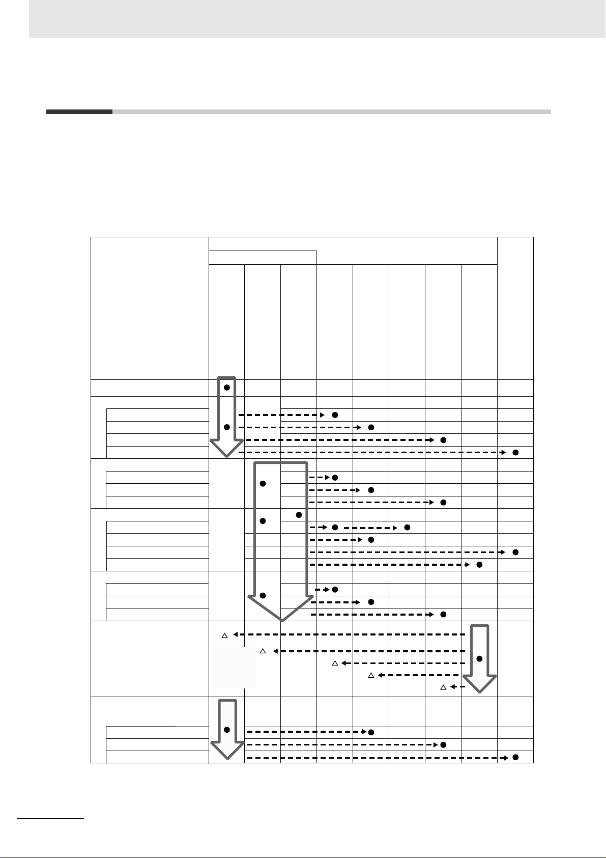
NJ-series User’s Manuals
Basic information
Introduction to NJ-series Controllers
Setting devices and hardware
Using motion control
Using EtherCAT
Using EtherNet/IP
Using CJ-series Units
Software settings
Using motion control
Using EtherCAT
Using EtherNet/IP
Programming
Using motion control
Using EtherCAT
Using CJ-series Units
Programming error processing
Testing operation and debugging
Using motion control
Using EtherCAT
Using EtherNet/IP
Maintenance
Using EtherCAT
Using EtherNet/IP
Using CJ-series Units
NJ-series CPU Unit
Hardware User´s Manual
NJ-series CPU Unit
Software User´s Manual
NJ-series Instructions
Reference Manual
NJ-series CPU Unit Motion
Control User´s Manual
NJ-series CPU Unit Built-in
EtherCAT Port User´s Manual
NJ-series Motion Control
Instructions Reference Manual
NJ-series CPU Unit Built-in
EtherNet/IP Port User´s Manual
NJ-series Troubleshooting Manual
CJ-series Special Unit Operation
Manuals for NJ-series CPU Unit
Troubleshooting and managing
errors in an NJ-series Controller
Use the
relevant
manuals for
references
according to
any error that
occurs.
Relevant Manuals
There are three manuals that provide basic information on the NJ-series CPU Units: the NJ-series CPU
Unit Hardware User’s Manual, the NJ-series CPU Unit Software User’s Manual, and the NJ-series
Instructions Reference Manual.
Most operations are performed from the Sysmac Studio Automation Software. Refer to the Sysmac Studio Version 1 Operation Manual (Cat. No. W504) for information on the Sysmac Studio.
Other manuals are necessary for specific system configurations and applications.
Read all of the manuals that are relevant to your system configuration and application to make the most
of the NJ-series CPU Unit.
2
CJ-series User Defined CAN Unit Operation Manual for NJ-series CPU Unit (W517)
Page 5

Manual Configuration
NJ-series CPU Unit Hardware User’s Manual (Cat. No. W500)
Section Description
Section 1
Introduction
Section 2
System Configuration
Section 3
Configuration Units
Section 4
Installation and Wiring
Section 5
Troubleshooting
Section 6
Inspection and Maintenance
Appendices
This section provides an introduction to the NJ-series Controllers and their features,
and gives the NJ-series Controller specifications.
This section describes the system configuration used for NJ-series Controllers.
This section describes the parts and functions of the configuration devices in the NJseries Controller configuration, including the CPU Unit and Configuration Units.
This section describes where and how to install the CPU Unit and Configuration Units
and how to wire them.
This section describes the event codes, error confirmation methods, and corrections
for errors that can occur.
This section describes the contents of periodic inspections, the service life of the Battery and Power Supply Units, and replacement methods for the Battery and Power
Supply Units.
The appendices provide the specifications of the Basic I/O Units, Unit dimensions,
load short-circuit protection detection, line disconnection detection, and measures for
EMC Directives.
Introduction
NJ-series CPU Unit Software User’s Manual (Cat. No. W501)
Section Description
Section 1
Introduction
Section 2
CPU Unit Operation
Section 3
I/O Ports, Slave Configuration, and
Unit Configuration
Section 4
Controller Setup
Section 5
Designing Tasks
Section 6
Programming
Section 7
Simulation, Transferring Projects to
the Physical CPU Unit, and Operation
Section 8
CPU Unit Status
Section 9
CPU Unit Functions
Section 10
Communications Setup
Section 11
Example of Actual Application Procedures
Section 12
Troubleshooting
Appendices
This section provides an introduction to the NJ-series Controllers and their features,
and gives the NJ-series Controller specifications.
This section describes the variables and control systems of the CPU Unit and CPU
Unit status.
This section describes how to use I/O ports, how to create the slave configuration
and unit configuration and how to assign functions.
This section describes the initial settings of the function modules.
This section describes the task system and types of tasks.
This section describes programming, including the programming languages and the
variables and instructions that are used in programming.
This section describes simulation of Controller operation and how to use the results
of simulation.
This section describes CPU Unit status.
This section describes the functionality provided by the CPU Unit.
This section describes how to go online with the CPU Unit and how to connect to
other devices.
This section describes the procedures that are used to actually operate an NJ-series
Controller.
This section describes the event codes, error confirmation methods, and corrections
for errors that can occur.
The appendices provide the CPU Unit specifications, task execution times, systemdefined variable lists, data attribute lists, CJ-series Unit memory information, CJseries Unit memory allocation methods, and data type conversion information.
CJ-series User Defined CAN Unit Operation Manual for NJ-series CPU Unit (W517)
3
Page 6

Introduction
Sysmac Studio Version 1 Operation Manual (Cat. No. W504)
Section 1
Introduction
Section 2
Installation and Uninstallation
Section 3
System Design
Section 4
Programming
Section 5
Online Connections to a Controller
Section 6
Debugging
Section 7
Other Functions
Section 8
Reusing Programming
Section 9
Support Software Provided with the
Sysmac Studio
Section 10
Troubleshooting
Appendices
Section Description
This section provides an overview and lists the specifications of the Sysmac Studio
and describes its features and components.
This section describes how to install and uninstall the Sysmac Studio.
This section describes the basic concepts for designing an NJ-series System with the
Sysmac Studio and the basic operating procedures.
This section describes how to create programs with the Sysmac Studio.
This section describes how to go online with a Controller.
This section describes how to debug the programs online on the Controller or debug
it offline with the Simulator.
This section describes Sysmac Studio functions other than system design functions.
This section describes how to reuse the programs that you create with the Sysmac
Studio.
This section describes the Support Software that is provided with the Sysmac Studio.
This section describes the error messages that are displayed when you check a program on the Sysmac Studio and how to correct those errors.
The appendices describe the following:
Driver Installation for Direct USB Cable Connection
Specifying One of Multiple Ethernet Interface Cards
Online Help
Simulation Instructions
CJ-series User Defined CAN Unit Operation Manual for NJ-series
CPU Unit (Cat. No. W517) (This Manual)
Section Description
Section 1
Features and System Configuration
Section 2
Nomenclature and Installation
Section 3
Data Exchange with the CPU Unit
Section 4
Message Communications
Section 5
Communications Timing
Section 6
Troubleshooting and Maintenance
Appendices ---
This section provides an introduction to the User Defined CAN Units and their features. It also describes the operating procedure and the specifications of the User
Defined CAN Units.
This section describes the nomenclature, functionality and installation of the User
Defined CAN Unit.
This section describes the data exchange between the CPU Unit and User Defined
CAN Unit and the definitions of the device variables for CJ-series Unit.
This section describes the message communications of the User Defined CAN Unit.
This section describes the communications timing of the User Defined CAN Unit and
the performances of the remote I/O communications and message communications.
This section describes the troubleshooting procedure, event logs and maintenance
procedure for the User Defined CAN Unit.
4
CJ-series User Defined CAN Unit Operation Manual for NJ-series CPU Unit (W517)
Page 7
Manual Structure
4-9
4 Installation and Wiring
NJ-series CPU Unit Hardware User’s Manual (W500)
s
t
i
n
U
gnitn
u
oM
3-4
4
s
t
ne
no
p
m
o
C
rel
l
o
r
t
n
oC
g
n
i
tc
e
n
noC
1
-
3-
4
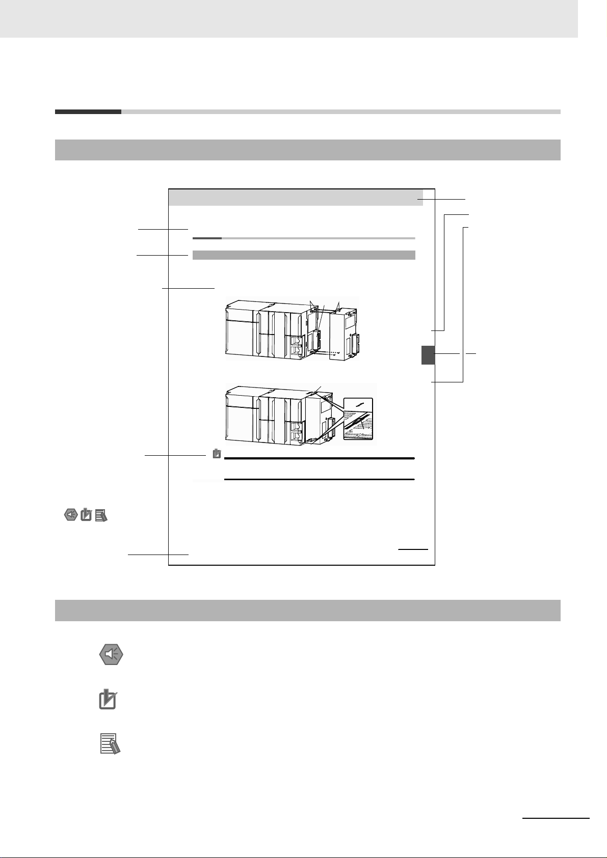
4-3 Mounting Units
The Units that make up an NJ-series Controller can be connected simply by pressing the Units together
and locking the sliders by moving them toward the back of the Units. The End Cover is connected in the
same way to the Unit on the far right side of the Controller.
1 Join the Units so that the connectors fit exactly.
2 The yellow sliders at the top and bottom of each Unit lock the Units together. Move the sliders
toward the back of the Units as shown below until they click into place.
Precautions for Correct UsePrecautions for Correct Use
The sliders on the tops and bottoms of the Powe r Supply Unit, CPU Unit, I/O Units, Special I/O
Units, and CPU Bus Units must be completely locked (until they click into place) after connecting
the adjacent Unit connectors.
4-3-1 Connecting Controller Components
Connector
Hook
Hook holes
Slider
Lock
Release
Move the sliders toward the back
until they lock into place.
Level 1 heading
Level 2 heading
Level 3 heading
Level 2 heading
A step in a procedure
Manual name
Special information
Level 3 heading
Page tab
Gives the current
headings.
Indicates a procedure.
Icons indicate
precautions, additional
information, or reference
information.
Gives the number
of the main section.
This illustration is provided only as a sample. It may not literally appear in this manual.
Page Structure
The following page structure is used in this manual.
Introduction
Special Information
Special information in this manual is classified as follows:
Precautions for Safe Use
Precautions on what to do and what not to do to ensure safe usage of the product.
Precautions for Correct Use
Precautions on what to do and what not to do to ensure proper operation and performance.
Additional Information
Additional information to read as required.
This information is provided to increase understanding or make operation easier.
Note References are provided to more detailed or related information.
CJ-series User Defined CAN Unit Operation Manual for NJ-series CPU Unit (W517)
5
Page 8

Introduction
Troubleshooting and Maintenance
Appendices
Communications Timing
6
5
Nomenclature and Installation
Data Exchange with the CPU Unit
Message Communications
4
3
2
1
2
3
4
5
6
A
1
1
I
A
I
Features and System Conguration
Index
Sections in this Manual
6
CJ-series User Defined CAN Unit Operation Manual for NJ-series CPU Unit (W517)
Page 9

CONTENTS
Introduction............................................................................................................... 1
Relevant Manuals ..................................................................................................... 2
Manual Configuration............................................................................................... 3
Manual Structure ...................................................................................................... 5
Sections in this Manual............................................................................................ 6
CONTENTS ................................................................................................................ 7
Read and Understand this Manual........................................................................ 10
Safety Precautions ................................................................................................. 13
Precautions for Safe Use ....................................................................................... 18
Precautions for Correct Use .................................................................................. 24
Regulations and Standards ................................................................................... 27
Unit Versions........................................................................................................... 29
Related Manuals ..................................................................................................... 31
Revision History ..................................................................................................... 32
Section 1 Features and System Configuration
1-1 User Defined CAN Unit Features ........................................................................................... 1-2
1-2 Overview of CAN Bus ............................................................................................................. 1-5
1-2-1 CAN Communication Protocol ................................................................................................... 1-6
1-2-2 Physical CAN Connection ........................................................................................................ 1-10
1-2-3 Principles of Data Exchange .....................................................................................................1-11
1-2-4 Principles of Non-Destructive Bitwise Arbitration ......................................................................1-11
1-2-5 Efficiency of Bus Allocation ...................................................................................................... 1-12
1-2-6 Message Frame Formats ......................................................................................................... 1-14
1-2-7 Detecting and Signaling Errors ................................................................................................ 1-15
1-2-8 Data Reliability of the CAN Protocol ........................................................................................ 1-17
1-2-9 Extended Format CAN Message ............................................................................................. 1-18
1-2-10 Implementations of the CAN Protocol ......................................................................................1-19
1-2-11 Configuring a CAN Network ..................................................................................................... 1-19
1-3 Specifications ....................................................................................................................... 1-20
1-3-1 User Defined CAN Unit ............................................................................................................ 1-20
1-4 Basic Operating Procedures ............................................................................................... 1-22
1-4-1 Network Installation Procedure ................................................................................................ 1-22
1-4-2 User Defined CAN Unit Startup Procedure .............................................................................. 1-23
CJ-series User Defined CAN Unit Operation Manual for NJ-series CPU Unit (W517)
7
Page 10

Section 2 Nomenclature and Installation
2-1 Nomenclature and Installation .............................................................................................. 2-2
2-1-1 Nomenclature and Functions .....................................................................................................2-2
2-1-2 Switch Settings ........................................................................................................................... 2-5
2-2 Installing the User Defined CAN Unit .................................................................................... 2-8
2-2-1 System Configuration Precautions .............................................................................................2-8
2-2-2 Mounting ....................................................................................................................................2-8
2-2-3 Handing Precautions ..................................................................................................................2-9
2-2-4 External Dimensions .................................................................................................................. 2-9
2-2-5 Unit States ................................................................................................................................ 2-10
Section 3 Data Exchange with the CPU Unit
3-1 Data Exchange with the CPU Unit ......................................................................................... 3-2
3-1-1 Data Flow ................................................................................................................................... 3-2
3-1-2 Accessing From the User Program ............................................................................................ 3-5
3-2 Device Variable for CJ-series Unit ........................................................................................ 3-8
3-2-1 Enable CAN Communications ....................................................................................................3-8
3-2-2 Status Communication ...............................................................................................................3-9
3-2-3 Number of Delayed Messages .................................................................................................3-12
3-2-4 Number of Received Messages Waiting to be Processed .......................................................3-12
Section 4 Message Communications
4-1 Overview .................................................................................................................................. 4-2
4-1-1 Outline of Message Communications ........................................................................................4-2
4-2 Unit Configuration and Control ............................................................................................. 4-4
4-2-1 Configure Memory Areas (2902) ................................................................................................ 4-4
4-2-2 Configure 11-Bit ID Output Message Buffer (2903) .................................................................4-10
4-2-3 Configure 29-Bit ID Output Message Buffer (2904) .................................................................4-12
4-2-4 Configure 11-Bit ID Input Message Buffer (2905) ....................................................................4-14
4-2-5 Configure 29-Bit ID Input Message Buffer (2906) ....................................................................4-16
4-2-6 Direct Transmit of an 11-bit ID CAN Message (2907) ..............................................................4-17
4-2-7 Direct Transmit of an 29-bit ID CAN Message (2908) ..............................................................4-19
4-2-8 Setting the CAN Bit Rate and Sample Point (2909) ................................................................. 4-21
4-2-9 Error Log Read (2102) .............................................................................................................4-22
4-2-10 Error Log Clear (2103) .............................................................................................................4-23
Section 5 Communications Timing
5-1 Performance ............................................................................................................................ 5-2
5-1-1 I/O Refresh Time ........................................................................................................................5-2
5-1-2 Output Message Evaluation Time .............................................................................................. 5-2
5-1-3 Input Message Processing Time ................................................................................................ 5-4
5-1-4 CAN Interface .............................................................................................................................5-5
5-1-5 I/O Response Time .................................................................................................................... 5-5
5-1-6 Transmission of CAN Messages ................................................................................................5-8
5-1-7 Reception of CAN Messages .....................................................................................................5-9
8
CJ-series User Defined CAN Unit Operation Manual for NJ-series CPU Unit (W517)
Page 11

Section 6 Troubleshooting and Maintenance
6-1 Overview .................................................................................................................................. 6-2
6-1-1 Troubleshooting the User Defined CAN Unit ............................................................................. 6-2
6-2 Troubleshooting with the User Defined CAN Unit Indicators ............................................. 6-4
6-2-1 Run LED Indicator ..................................................................................................................... 6-4
6-2-2 ERR LED Indicator .................................................................................................................... 6-5
6-2-3 Two 7-segment Display ............................................................................................................. 6-5
6-2-4 Two Dot Indicators ..................................................................................................................... 6-6
6-3 Error Log Functions ............................................................................................................... 6-7
6-3-1 Error Log Table .......................................................................................................................... 6-7
6-3-2 Error Codes and Detail Codes ................................................................................................... 6-8
6-3-3 Status Information ...................................................................................................................... 6-8
6-4 Troubleshooting ................................................................................................................... 6-10
6-4-1 CPU Unit’s ERR/ALM Indicator Lit or Flashing ........................................................................ 6-10
6-5 Event Logs ............................................................................................................................ 6-11
6-5-1 Overview of the Event Logs ......................................................................................................6-11
6-5-2 Error Table ............................................................................................................................... 6-12
6-5-3 Error Descriptions .................................................................................................................... 6-12
6-6 Maintenance and Replacement ........................................................................................... 6-16
6-6-1 Cleaning ................................................................................................................................... 6-16
6-6-2 Inspection ................................................................................................................................ 6-16
6-6-3 Replacing Faulty Units ............................................................................................................. 6-17
Appendices
A-1 Differences in Available Functions Depending on the CPU Unit (NJ/CJ-series) to be
Connected ...............................................................................................................................A-2
A-1-1 Differences in Available Functions .............................................................................................A-2
A-1-2 Differences in Accessing from User Program ............................................................................A-2
A-2 User Program Example ..........................................................................................................A-4
Index
CJ-series User Defined CAN Unit Operation Manual for NJ-series CPU Unit (W517)
9
Page 12

Read and Understand this Manual
Please read and understand this manual before using the product. Please consult your OMRON representative
if you have any questions or comments.
Warranty and Limitations of Liability
WARRANTY
OMRON's exclusive warranty is that the products are free from defects in materials and workmanship for a
period of one year (or other period if specified) from date of sale by OMRON.
OMRON MAKES NO WARRANTY OR REPRESENTATION, EXPRESS OR IMPLIED, REGARDING NONINFRINGEMENT, MERCHANTABILITY, OR FITNESS FOR PARTICULAR PURPOSE OF THE
PRODUCTS. ANY BUYER OR USER ACKNOWLEDGES THAT THE BUYER OR USER ALONE HAS
DETERMINED THAT THE PRODUCTS WILL SUITABLY MEET THE REQUIREMENTS OF THEIR
INTENDED USE. OMRON DISCLAIMS ALL OTHER WARRANTIES, EXPRESS OR IMPLIED.
LIMITATIONS OF LIABILITY
OMRON SHALL NOT BE RESPONSIBLE FOR SPECIAL, INDIRECT, OR CONSEQUENTIAL DAMAGES,
LOSS OF PROFITS OR COMMERCIAL LOSS IN ANY WAY CONNECTED WITH THE PRODUCTS,
WHETHER SUCH CLAIM IS BASED ON CONTRACT, WARRANTY, NEGLIGENCE, OR STRICT
LIABILITY.
In no event shall the responsibility of OMRON for any act exceed the individual price of the product on which
liability is asserted.
IN NO EVENT SHALL OMRON BE RESPONSIBLE FOR WARRANTY, REPAIR, OR OTHER CLAIMS
REGARDING THE PRODUCTS UNLESS OMRON'S ANALYSIS CONFIRMS THAT THE PRODUCTS
WERE PROPERLY HANDLED, STORED, INSTALLED, AND MAINTAINED AND NOT SUBJECT TO
CONTAMINATION, ABUSE, MISUSE, OR INAPPROPRIATE MODIFICATION OR REPAIR.
10
CJ-series User Defined CAN Unit Operation Manual for NJ-series CPU Unit (W517)
Page 13

Application Considerations
SUITABILITY FOR USE
OMRON shall not be responsible for conformity with any standards, codes, or regulations that apply to the
combination of products in the customer's application or use of the products.
At the customer's request, OMRON will provide applicable third party certification documents identifying
ratings and limitations of use that apply to the products. This information by itself is not sufficient for a
complete determination of the suitability of the products in combination with the end product, machine,
system, or other application or use.
The following are some examples of applications for which particular attention must be given. This is not
intended to be an exhaustive list of all possible uses of the products, nor is it intended to imply that the uses
listed may be suitable for the products:
• Outdoor use, uses involving potential chemical contamination or electrical interference, or conditions or
uses not described in this manual.
• Nuclear energy control systems, combustion systems, railroad systems, aviation systems, medical
equipment, amusement machines, vehicles, safety equipment, and installations subject to separate
industry or government regulations.
• Systems, machines, and equipment that could present a risk to life or property.
Please know and observe all prohibitions of use applicable to the products.
NEVER USE THE PRODUCTS FOR AN APPLICATION INVOLVING SERIOUS RISK TO LIFE OR
PROPERTY WITHOUT ENSURING THAT THE SYSTEM AS A WHOLE HAS BEEN DESIGNED TO
ADDRESS THE RISKS, AND THAT THE OMRON PRODUCTS ARE PROPERLY RATED AND
INSTALLED FOR THE INTENDED USE WITHIN THE OVERALL EQUIPMENT OR SYSTEM.
PROGRAMMABLE PRODUCTS
OMRON shall not be responsible for the user's programming of a programmable product, or any
consequence thereof.
CJ-series User Defined CAN Unit Operation Manual for NJ-series CPU Unit (W517)
11
Page 14

Disclaimers
CHANGE IN SPECIFICATIONS
Product specifications and accessories may be changed at any time based on improvements and other
reasons.
It is our practice to change model numbers when published ratings or features are changed, or when
significant construction changes are made. However, some specifications of the products may be changed
without any notice. When in doubt, special model numbers may be assigned to fix or establish key
specifications for your application on your request. Please consult with your OMRON representative at any
time to confirm actual specifications of purchased products.
DIMENSIONS AND WEIGHTS
Dimensions and weights are nominal and are not to be used for manufacturing purposes, even when
tolerances are shown.
PERFORMANCE DATA
Performance data given in this manual is provided as a guide for the user in determining suitability and does
not constitute a warranty. It may represent the result of OMRON's test conditions, and the users must
correlate it to actual application requirements. Actual performance is subject to the OMRON Warranty and
Limitations of Liability.
ERRORS AND OMISSIONS
The information in this manual has been carefully checked and is believed to be accurate; however, no
responsibility is assumed for clerical, typographical, or proofreading errors, or omissions.
12
CJ-series User Defined CAN Unit Operation Manual for NJ-series CPU Unit (W517)
Page 15
Safety Precautions
Definition of Precautionary Information
The following notation is used in this manual to provide precautions required to ensure safe usage of an
NJ-series Controller. The safety precautions that are provided are extremely important to safety. Always
read and heed the information provided in all safety precautions.
The following notation is used.
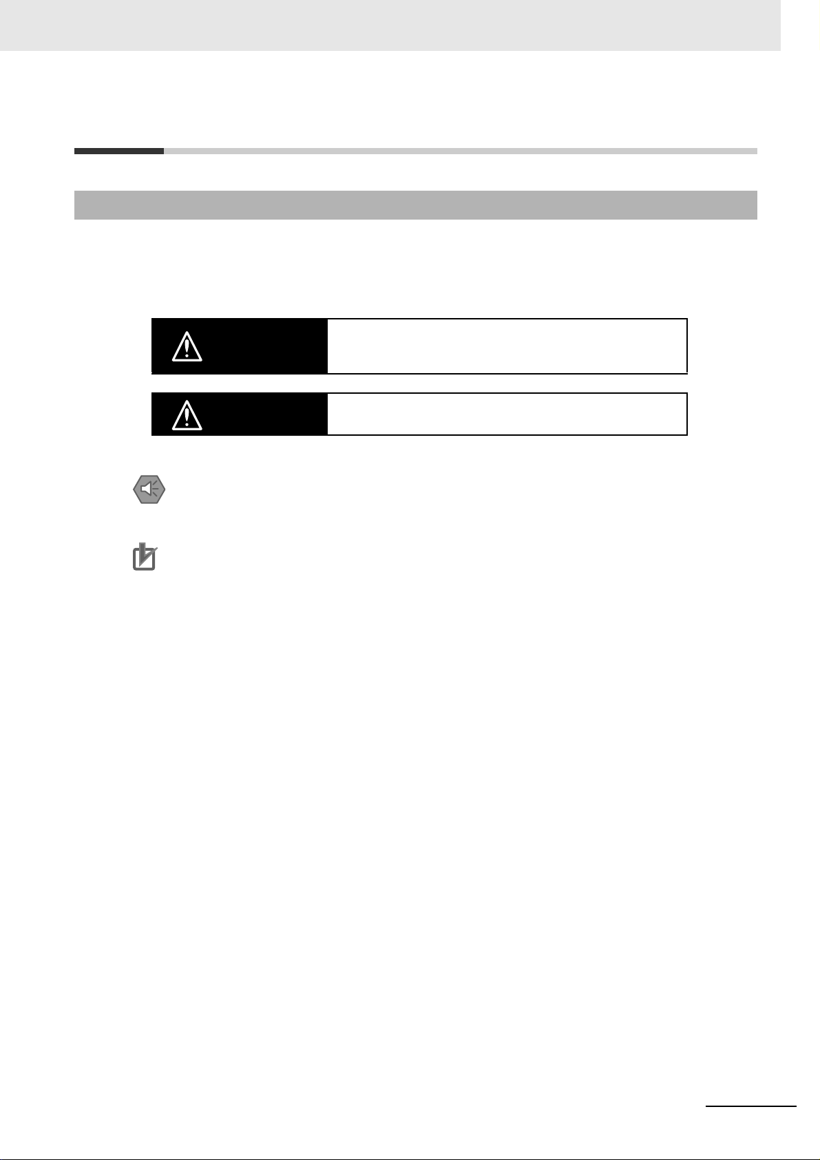
Indicates a potentially hazardous situation which, if not avoided,
WARNING
could result in death or serious injury. Additionally, there may be
severe property damage.
Caution
Precautions for Safe Use
Indicates precautions on what to do and what not to do to ensure safe usage of the product.
Precautions for Correct Use
Indicates precautions on what to do and what not to do to ensure proper operation and performance.
Indicates a potentially hazardous situation which, if not avoided,
may result in minor or moderate injury, or property damage.
CJ-series User Defined CAN Unit Operation Manual for NJ-series CPU Unit (W517)
13
Page 16
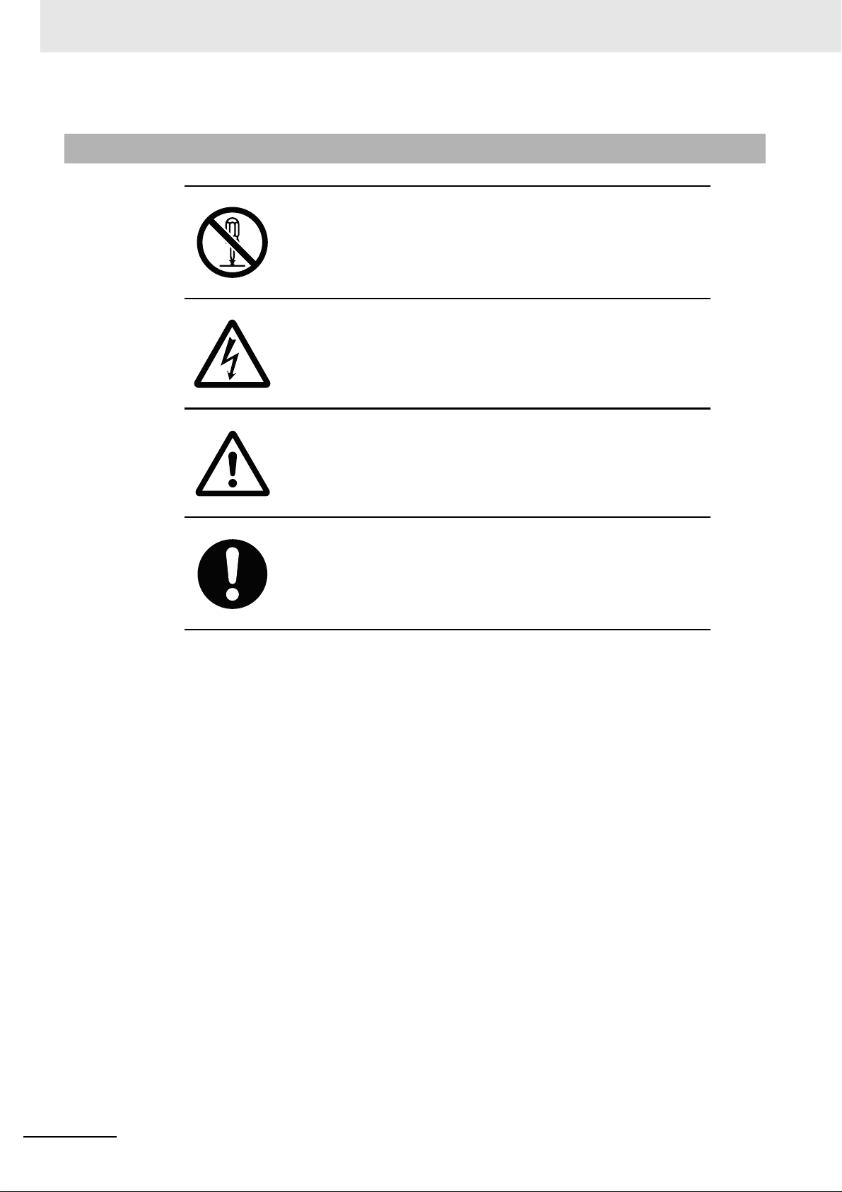
Symbols
The circle and slash symbol indicates operations that you must not do.
The specific operation is shown in the circle and explained in text.
This example indicates prohibiting disassembly.
The triangle symbol indicates precautions (including warnings).
The specific operation is shown in the triangle and explained in text.
This example indicates a precaution for electric shock.
The triangle symbol indicates precautions (including warnings).
The specific operation is shown in the triangle and explained in text.
This example indicates a general precaution.
The filled circle symbol indicates operations that you must do.
The specific operation is shown in the circle and explained in text.
This example shows a general precaution for something that you must do.
14
CJ-series User Defined CAN Unit Operation Manual for NJ-series CPU Unit (W517)
Page 17
WARNING
During Power Supply
Do not touch any of the terminals or terminal blocks while the power is being
supplied. Doing so may result in electric shock.
Do not attempt to take any Unit apart. In particular, high-voltage parts are
present in the Power Supply Unit while power is supplied or immediately
after power is turned OFF. Touching any of these parts may result in electric
shock. There are sharp parts inside the Unit that may cause injury.
Fail-safe Measures
Provide safety measures in external circuits to ensure safety in the system if
an abnormality occurs due to malfunction of the CPU Unit, other Units, or
slaves or due to other external factors affecting operation. Not doing so may
result in serious accidents due to incorrect operation.
Emergency stop circuits, interlock circuits, limit circuits, and similar safety
measures must be provided in external control circuits.
The Controller outputs may remain ON or OFF due to deposition or burning
of the output relays or destruction of the output transistors. As a countermeasure for such problems, external safety measures must be provided to
ensure safe operation of the system.
The CPU Unit will turn OFF all outputs from Basic Output Units in the following cases.
• If an error occurs in the power supply
• If the power supply connection becomes faulty
• If a CPU watchdog timer error or CPU reset occurs
• If a major fault level Controller error occurs
• While the CPU Unit is on standby until RUN mode is entered after the
power is turned ON
External safety measures must be provided to ensure safe operation of the
system even if the outputs turn OFF.
If external power supplies for slaves or other devices are overloaded or
short-circuited, the voltage will drop, outputs will turn OFF, and the system
may be unable to read inputs. Provide external safety measures in controls
with monitoring of external power supply voltage as required so that the system operates safely in such a case.
CJ-series User Defined CAN Unit Operation Manual for NJ-series CPU Unit (W517)
15
Page 18

WARNING
Fail-safe Measures
Unintended outputs may occur when an error occurs in variable memory or
in memory used for CJ-series Units. As a countermeasure for such problems, external safety measures must be provided to ensure safe operation of
the system.
Provide measures in the communications system and user program to
ensure safety in the overall system even if errors or malfunctions occur in
data link communications or remote I/O communications.
If there is interference in remote I/O communications or if a major fault level
error occurs, output status will depend on the products that are used.
Confirm the operation that will occur when there is interference in communications or a major fault level error, and implement safety measures.
Correctly set all of the EtherCAT slaves.
The NJ-series Controller continues normal operation for a certain period of
time when a momentary power interruption occurs. This means that the NJseries Controller may receive incorrect signals from external devices that are
also affected by the power interruption. Accordingly, take suitable actions,
such as external fail-safe measures and interlock conditions, to monitor the
power supply voltage of the external device as required.
You must take fail-safe measures to ensure safety in the event of incorrect,
missing, or abnormal signals caused by broken signal lines, momentary
power interruptions, or other causes. Not doing so may result in serious accidents due to incorrect operation.
Voltage and Current Inputs
Make sure that the voltages and currents that are input to the Units and
slaves are within the specified ranges.
Inputting voltages or currents that are outside of the specified ranges may
cause accidents or fire.
16
Downloading
Always confirm safety at the destination before you transfer a user program,
configuration data, setup data, device variables, or values in memory used
for CJ-series Units from the Sysmac Studio. The devices or machines may
perform unexpected operation regardless of the operating mode of the CPU
Unit.
CJ-series User Defined CAN Unit Operation Manual for NJ-series CPU Unit (W517)
Page 19
Caution
Application
Do not touch any Unit when power is being supplied or immediately after the
power supply is turned OFF. Doing so may result in burn injury.
Wiring
Be sure that all terminal screws and cable connector screws are tightened to
the torque specified in the relevant manuals. The loose screws may result in
fire or malfunction.
Online Editing
Execute online editing only after confirming that no adverse effects will be
caused by deviations in the timing of I/O. If you perform online editing, the
task execution time may exceed the task period, I/O may not be refreshed
with external devices, input signals may not be read, and output timing may
change.
CJ-series User Defined CAN Unit Operation Manual for NJ-series CPU Unit (W517)
17
Page 20

Precautions for Safe Use
Disassembly and Dropping
• Do not attempt to disassemble, repair, or modify any Units. Doing so may result in malfunction or fire.
• Do not drop any Unit or subject it to abnormal vibration or shock. Doing so may result in Unit malfunction or burning.
Mounting
• The sliders on the tops and bottoms of the Power Supply Unit, CPU Unit, I/O Units, Special I/O Unit,
and CPU Bus Units must be completely locked (until they click into place) after connecting the adjacent Unit connectors.
Installation
• Always connect to a ground of 100 Ω or less when installing the Units. A ground of 100 Ω or less
must be installed when shorting the GR and LG terminals on the Power Supply Unit.
Wiring
• Follow the instructions in this manual to correctly perform wiring.
Double-check all wiring and switch settings before turning ON the power supply.
• Use crimp terminals for wiring.
Do not connect bare stranded wires directly to terminals.
• Do not pull on the cables or bend the cables beyond their natural limit.
Do not place heavy objects on top of the cables or other wiring lines. Doing so may break the cables.
• Mount terminal blocks and connectors only after checking the mounting location carefully.
• Be sure that the terminal blocks, expansion cables, and other items with locking devices are properly
locked into place.
• Always remove any dustproof labels that are on the top of the Units when they are shipped before
you turn ON the power supply. If the labels are not removed, heat will accumulate and malfunctions
may occur.
• Before you connect a computer to the CPU Unit, disconnect the power supply plug of the computer
from the AC outlet. Also, if the computer has an FG terminal, make the connections so that the FG
terminal has the same electrical potential as the FG (GR) terminal on the Power Supply Unit. A difference in electric potential between the computer and Controller may cause failure or malfunction.
• If the external power supply to an Output Unit or slave has polarity, connect it with the correct polarity.
If the polarity is reversed, current may flow in the reverse direction and damage the connected
devices regardless of the operation of the Controller.
18
Power Supply Design
• Do not exceed the rated supply capacity of the Power Supply Units in the NJ-series Controller. The
rated supply capacities are given in the NJ-series CPU Unit Hardware User’s Manual
(Cat. No. W500).
If the capacity is exceeded, operation may stop, malfunctions may occur, or data may not be backed
up normally for power interruptions.
Use NJ-series Power Supply Units for both the NJ-series CPU Rack and Expansion Racks.
Operation is not possible if a CJ-series Power Supply Unit is used with an NJ-series CPU Unit or an
NJ-series Power Supply Unit is used with a CJ-series CPU Unit.
CJ-series User Defined CAN Unit Operation Manual for NJ-series CPU Unit (W517)
Page 21

• Do not apply voltages or connect loads to the Output Units or slaves in excess of the maximum ratings.
• Surge current occurs when the power supply is turned ON. When selecting fuses or breakers for
external circuits, consider the above precaution and allow sufficient margin in shut-off performance.
Refer to the relevant manuals for surge current specifications. Refer to the NJ-series CPU Unit Hard-
ware User’s Manual (Cat. No. W500) for surge current specifications.
• If the full dielectric strength voltage is applied or turned OFF using the switch on the tester, the generated impulse voltage may damage the Power Supply Unit. Use the adjustment on the tester to gradually increase and decrease the voltage.
• Apply the voltage between the Power Supply Unit's L1 or L2 terminal and the GR terminal when testing insulation and dielectric strength. You do not have to disconnect the LG and GR terminals to perform these tests.
• Do not supply AC power from an inverter or other device with a square-wave output. Internal temperature rise may result in smoking or burning. Always input a sinusoidal wave with the frequency that is
given in the NJ-series CPU Unit Hardware User’s Manual (Cat. No. W500).
• Install external breakers and take other safety measures against short-circuiting in external wiring.
Turning ON the Power Supply
• It takes up to approximately 10 to 20 s to enter RUN mode after the power is turned ON. During that
time, outputs will be OFF or will be the values specified in the Unit or slave settings, and external
communications cannot be performed. Use the RUN output on the Power Supply Unit, for example,
to implement fail-safe circuits so that external devices do not operate incorrectly.
• Configure the external circuits so that the power supply to the control system turns ON only after the
power supply to the Controller has turned ON. If the power supply to the Controller is turned ON after
the control power supply, temporary errors may result in incorrect control system signals because the
output terminals on Output Units may momentarily turn ON when power supply is turned ON to the
Controller.
Actual Operation
• Check the user program, data, and parameter settings for proper execution before you use them for
actual operation.
Turning OFF the Power Supply
• Never turn OFF the power supply to the Controller when the BUSY indicator is flashing. While the
BUSY indicator is lit, the user program and settings in the CPU Unit are being backed up in the builtin non-volatile memory. This data will not be backed up correctly if the power supply is turned OFF.
Also, a major fault level Controller error will occur the next time you start operation, and operation will
stop.
• Do not turn OFF the power supply or remove the SD Memory Card while SD Memory Card access is
in progress (i.e., while the SD BUSY indicator flashes). Data may become corrupted, and the Controller will not operate correctly if it uses corrupted data. To remove the SD Memory Card from the CPU
Unit while the power supply is ON, press the SD Memory Card power supply switch and wait for the
SD BUSY indicator to turn OFF before you remove the SD Memory Card.
• Do not disconnect the cable or turn OFF the power supply to the Controller when downloading data
or the user program from Support Software.
• Always turn OFF the power supply to the Controller before you attempt any of the following.
• Mounting or removing I/O Units or the CPU Unit
• Assembling the Units
• Setting DIP switches or rotary switches
• Connecting cables or wiring the system
• Connecting or disconnecting the connectors
CJ-series User Defined CAN Unit Operation Manual for NJ-series CPU Unit (W517)
19
Page 22

The Power Supply Unit may continue to supply power to the rest of the Controller for a few seconds
after the power supply turns OFF. The PWR indicator is lit during this time. Confirm that the PWR
indicator is not lit before you perform any of the above.
Operation
• Confirm that no adverse effect will occur in the system before you attempt any of the following.
• Changing the operating mode of the CPU Unit (including changing the setting of the Operating
Mode at Startup)
• Changing the user program or settings
• Changing set values or present values
• Forced refreshing
• Always sufficiently check the safety at the connected devices before you change the settings of an
EtherCAT slave or Special Unit.
• If two different function modules are used together, such as when you use CJ-series Basic Output
Units and EtherCAT slave outputs, take suitable measures in the user program and external controls
to ensure that safety is maintained in the controlled system if one of the function modules stops. The
relevant outputs will stop if a partial fault level error occurs in one of the function modules.
• Always confirm safety at the connected equipment before you reset Controller errors with an event
level of partial fault or higher for the EtherCAT Master Function Module.
When the error is reset, all slaves that were in any state other than Operational state due to a Controller error with an event level of partial fault or higher (in which outputs are disabled) will go to Operational state and the outputs will be enabled.
Before you reset all errors, confirm that no Controller errors with an event level of partial fault have
occurred for the EtherCAT Master Function Module.
• Always confirm safety at the connected equipment before you reset Controller errors for a CJ-series
Special Unit. When a Controller error is reset, the Unit where the Controller error with an event level
of observation or higher will be restarted.
Before you reset all errors, confirm that no Controller errors with an event level of observation or
higher have occurred for the CJ-series Special Unit. Observation level events do not appear on the
Controller Error Tab Page, so it is possible that you may restart the CJ-series Special Unit without
intending to do so.
You can check the status of the _CJB_UnitErrSta[0,0] to _CJB_UnitErrSta[3,9] error status variables
on a Watch Tab Page to see if an observation level Controller error has occurred.
20
Battery Backup
• The user program and initial values for the variables are stored in non-volatile memory in the CPU
Unit. The present values of variables with the Retain attribute and the values of the Holding, DM, and
EM Areas in the memory used for CJ-series Units are backed up by a Battery. If the Battery is not
connected or the Battery is exhausted, the CPU Unit detects a Battery-backup Memory Check Error.
If that error is detected, variables with a Retain attribute are set to their initial values and the Holding,
DM, and EM Areas in memory used for CJ-series Units are cleared to all zeros. Perform thorough
verifications and provide sufficient measures to ensure that the devices perform safe operation for
the initial values of the variables with Retain attributes and the resulting operation.
Debugging
• Forced refreshing ignores the results of user program execution and refreshes I/O with the specified
values. If forced refreshing is used for inputs for which I/O refreshing is not supported, the inputs will
first take the specified values, but they will then be overwritten by the user program. This operation
differs from the force-set/reset functionality of the CJ-series PLCs.
CJ-series User Defined CAN Unit Operation Manual for NJ-series CPU Unit (W517)
Page 23

• You cannot upload or download information for forced refreshing with the Sysmac Studio.
After downloading data that contains forced refreshing, change to RUN mode and then use the
Sysmac Studio to perform the operation for forced refreshing.
Depending on the difference in the forced status, the control system may operate unexpectedly.
• Do not specify the same address for the AT specification for more than one variable.
Doing so would allow the same entity to be accessed with different variable names, which would
make the user program more difficult to understand and possibly cause programming mistakes.
General Communications
• When you use data link communications, check the error information given in the status flags to
make sure that no error has occurred in the source device. Write the user program to use the
received data only if there is no error. If there is an error in the source device, the data for the data
link may contain incorrect values.
• Unexpected operation may result if inappropriate data link tables are set. Even if appropriate data link
tables have been set, confirm that the controlled system will not be adversely affected before you
transfer the data link tables. The data links start automatically after the data link tables are transferred.
• All CPU Bus Units are restarted when routing tables are transferred from Support Software to the
CPU Unit. Restarting these Units is required to read and enable the new routing tables. Confirm that
the system will not be adversely affected by restarting before you transfer the routing tables.
• Tag data links will stop between related nodes while tag data link parameters are transferred during
Controller operation. Confirm that the system will not be adversely affected before you transfer the
tag data link parameters.
EtherNet/IP Communications
• All related EtherNet/IP nodes are reset when you transfer settings for the built-in EtherNet/IP port
(including IP addresses and tag data links settings). This is performed to read and enable the settings. Confirm that the system will not be adversely affected by resetting nodes before you transfer
the settings.
• If EtherNet/IP tag data links (cyclic communications) are used with a repeating hub, the communications load on the network will increase. This will increase collisions and may prevent stable communications. Do not use repeating hubs on networks where tag data links are used. Use an Ethernet
switch instead.
EtherCAT Communications
• Make sure that the communications distance, number of nodes connected, and method of connection for EtherCAT are within specifications.
Do not connect EtherCAT communications to EtherNet/IP, a standard in-house LAN, or other networks. An overload may cause the network to fail or malfunction.
• Malfunctions or unexpected operation may occur for some combinations of EtherCAT revisions of the
master and slaves. If you disable the revision check in the network settings, use the Sysmac Studio
to check the slave revision settings in the master and the actual slave revisions, and then make sure
that functionality is compatible in the slave manuals or other references. You can check the actual
slave revisions from the Sysmac Studio or on slave nameplates.
• After you transfer the user program, the CPU Unit is restarted. Communications with the EtherCAT
slaves are cut off for up to 45 seconds. During that period, the slave outputs behave according to the
slave settings.
Before you transfer the user program, confirm that the system will not be adversely affected.
• If the Fail-soft Operation parameter is set to stop operation, process data communications will stop
for all slaves when an EtherCAT communications error is detected in a slave. For this reason, if
Servo Drives are connected, the Servos for all axes will be turned OFF. Make sure that the Fail-soft
Operation parameter setting results in safe operation when a device error occurs.
CJ-series User Defined CAN Unit Operation Manual for NJ-series CPU Unit (W517)
21
Page 24

• EtherCAT communications are not always established immediately after the power supply is turned
ON. Use the system-defined variables in the user program to confirm that communications are established before attempting control operations.
• If frames sent to EtherCAT slaves are lost due to noise or other causes, slave I/O data is not communicated, and the intended operation is sometimes not achieved. If noise countermeasures are
required, use the _EC_InDataInvalid (Input Data Disable) system-defined variable as an interlock
condition in the user program.
Refer to the NJ-series CPU Unit Built-in EtherCAT Port User’s Manual (Cat. No. W505) for details.
The slave outputs behave according to the slave settings. Refer to the manuals for the slaves for
details.
• When an EtherCAT slave is disconnected, communications will stop and control of the outputs will be
lost not only for the disconnected slave, but for all slaves connected after it. Confirm that the system
will not be adversely affected before you disconnect a slave.
• If you disconnect the cable from an EtherCAT slave to disconnect it from the network, any current
communications frames may be lost. If frames are lost, slave I/O data is not communicated, and the
intended operation is sometimes not achieved. Perform the following processing for a slave that
needs to be replaced.
Program the _EC_InDataInvalid (Input Data Disable) system-defined variable as an interlock condition.
Set the Impermissible Number of Continuous Timeouts setting in the EtherCAT master to at
least 2.
Refer to the NJ-series CPU Unit Built-in EtherCAT Port User’s Manual (Cat. No. W505) for details.
Motion Control
• Confirm the axis number carefully before you perform an MC Test Run.
• The motor is stopped if communications are interrupted between the Sysmac Studio and the CPU
Unit during an MC Test Run. Connect the communications cable between the computer and CPU
Unit securely and confirm that the system will not be adversely affected before you perform an
MC Test Run.
• Always execute the Save Cam Table instruction if you change any of the cam data from the user program in the CPU Unit or from the Sysmac Studio. If the cam data is not saved, the previous condition
will be restored when the power is turned ON again, possibly causing unexpected machine operation.
• The positive drive prohibit input (POT), negative drive prohibit input (NOT), and home proximity input
(DEC) of the Servo Drive are used by the MC Function Module as the positive limit input, negative
limit input, and home proximity input. Make sure that the signal widths for all of these input signals
are longer than the control period of the MC Function Module. If the input signal widths are shorter
than the control period, the MC Function Module may not be able to detect the input signals, resulting
in incorrect operation.
Battery Replacement
• The Battery may leak, rupture, heat, or ignite. Never short-circuit, charge, disassemble, heat, or
incinerate the Battery or subject it to strong shock.
• Dispose of any Battery that has been dropped on the floor or otherwise subjected to excessive
shock. Batteries that have been subjected to shock may leak if they are used.
• UL standards require that only an experienced engineer replace the Battery. Make sure that an experienced engineer is in charge of Battery replacement.
• Apply power for at least five minutes before changing the Battery. Install a new Battery within five
minutes (at 25°C) of turning OFF the power supply. If power is not supplied for at least 5 minutes, the
saved data may be lost.
22
CJ-series User Defined CAN Unit Operation Manual for NJ-series CPU Unit (W517)
Page 25

Unit Replacement
• We recommend replacing the Battery with the power turned OFF to prevent the CPU Unit’s sensitive
internal components from being damaged by static electricity and to prevent malfunctions. The Battery can be replaced without turning OFF the power supply. To do so, always touch a grounded piece
of metal to discharge static electricity from your body before you start the procedure.
After you replace the Battery, connect the Sysmac Studio and clear the Low Battery Voltage error.
• Make sure that the required data, including the user program, configurations, settings, variables, and
memory used for CJ-series Units, is transferred to a CPU Unit that was replaced and to externally
connected devices before restarting operation.
Be sure to include the routing tables, network parameters, and other CPU Bus Unit data, which are
stored in the CPU Unit.
Disposal
• Dispose of the product and Batteries according to local ordinances as they apply.
• The following information must be displayed for all products that contain primary lithium batteries with
a perchlorate content of 6 ppb or higher when shipped to or transported through the State of California, USA.
Perchlorate Material - special handling may apply.
See www.dtsc.ca.gov/hazardouswaste/perchlorate.
• The CPU Unit contains a primary lithium battery with a perchlorate content of 6 ppb or higher. Place
the above information on the individual boxes and shipping boxes when shipping finished products
that contain a CPU Unit to the State of California, USA.
Using the User Defined CAN Units
• When adding a new node to the network, make sure that the baud rate is the same as other nodes.
• Use specified communications cables.
• Do not extend connection distances beyond the ranges given in the specifications.
CJ-series User Defined CAN Unit Operation Manual for NJ-series CPU Unit (W517)
23
Page 26

Precautions for Correct Use
Storage, Mounting, and Wiring
• Do not operate or store the Controller in the following locations. Operation may stop or malfunctions
may occur.
• Locations subject to direct sunlight
• Locations subject to temperatures or humidity outside the range specified in the specifications
• Locations subject to condensation as the result of severe changes in temperature
• Locations subject to corrosive or flammable gases
• Locations subject to dust (especially iron dust) or salts
• Locations subject to exposure to water, oil, or chemicals
• Locations subject to shock or vibration
• Take appropriate and sufficient countermeasures when installing the Controller in the following locations.
• Locations subject to strong, high-frequency noise
• Locations subject to static electricity or other forms of noise
• Locations subject to strong electromagnetic fields
• Locations subject to possible exposure to radioactivity
• Locations close to power lines
• Before touching a Unit, be sure to first touch a grounded metallic object in order to discharge any
static build-up.
• Install the Controller away from sources of heat and ensure proper ventilation. Not doing so may
result in malfunction, in operation stopping, or in burning.
• An I/O bus check error will occur and the Controller will stop if an I/O Connecting Cable’s connector is
disconnected from the Rack. Be sure that the connectors are secure.
• Do not allow foreign matter to enter the openings in the Unit. Doing so may result in Unit burning,
electric shock, or failure.
• Do not allow wire clippings, shavings, or other foreign material to enter any Unit. Otherwise, Unit
burning, failure, or malfunction may occur. Cover the Units or take other suitable countermeasures,
especially during wiring work.
• For EtherCAT and EtherNet/IP, use the connection methods and cables that are specified in the NJ-
series CPU Unit Built-in EtherCAT Port User’s Manual (Cat. No. W505) and the NJ-series CPU Unit
Built-in EtherNet/IP Port User’s Manual (Cat. No. W506). Otherwise, communications may be faulty.
• Use the rated power supply voltage for the Power Supply Units. Take appropriate measures to
ensure that the specified power with the rated voltage and frequency is supplied in places where the
power supply is unstable.
• Make sure that the current capacity of the wire is sufficient. Otherwise, excessive heat may be generated. When cross-wiring terminals, the total current for all the terminals will flow in the wire. When
wiring cross-overs, make sure that the current capacity of each of the wires is not exceeded.
• Do not touch the terminals on the Power Supply Unit immediately after turning OFF the power supply.
Residual voltage may cause electrical shock.
• If you use reed switches for the input contacts for AC Input Units, use switches with a current capacity of 1 A or greater.
If the capacity of the reed switches is too low, surge current may fuse the contacts.
24
CJ-series User Defined CAN Unit Operation Manual for NJ-series CPU Unit (W517)
Page 27

Error Processing
• In applications that use the results of instructions that read the error status, consider the affect on the
system when errors are detected and program error processing accordingly. For example, even the
detection of a minor error, such as Battery replacement during operation, can affect the system
depending on how the user program is written.
Unit Replacement
• If you replace a CPU Bus Unit or Special I/O Unit, refer to operation manual for the Unit for information on the data required for individual Units and redo the necessary settings.
• The absolute encoder home offset is backed up with a Battery in the CPU Unit.
When you change the combination of the CPU Unit and Servomotor, e.g., when you add or replace a
Servomotor, define home again.
To restore the information without changing the CPU Unit-Servomotor combination, remove the
absolute encoder home offset from the data to restore.
Task Settings
• If a Task Period Exceeded error occurs, shorten the programs to fit in the task period or increase the
setting of the task period.
Motion Control
• Use the system-defined variable in the user program to confirm that EtherCAT communications are
established before you attempt to execute motion control instructions. Motion control instructions are
not executed normally if EtherCAT communications are not established.
• Use the system-defined variables to monitor for errors in communications with the slaves that are
controlled by the motion control function module. Motion control instructions are not executed normally if an error occur in slave communications.
• Before you start an MC Test Run, make sure that the operation parameters are set correctly.
• Do not download motion control settings during an MC Test Run.
EtherCAT Communications
• Do not disconnect the EtherCAT slave cables during operation. The outputs will become unstable.
• Set the Servo Drives to stop operation if an error occurs in EtherCAT communications between the
Controller and a Servo Drive.
Battery Replacement
• Be sure to install a replacement Battery within two years of the production date shown on the Battery
label.
• Turn ON the power after replacing the Battery for a CPU Unit that has been unused for a long time.
Leaving the CPU Unit unused again without turning ON the power even once after the Battery is
replaced may result in a shorter Battery life.
• When you replace the Battery, use the CJ1W-BAT01 Battery Set.
CJ-series User Defined CAN Unit Operation Manual for NJ-series CPU Unit (W517)
25
Page 28

SD Memory Cards
• Insert the SD Memory Card all the way.
• Do not turn OFF the power supply to the Controller during SD Memory Card access. The files may be
corrupted.
If there is a corrupted file in the SD Memory Card, the file is automatically deleted by the restoration
function when the power supply is turned ON.
26
CJ-series User Defined CAN Unit Operation Manual for NJ-series CPU Unit (W517)
Page 29

Regulations and Standards
Conformance to EC Directives
Applicable Directives
• EMC Directives
• Low Voltage Directive
Concepts
EMC Directive
OMRON devices that comply with EC Directives also conform to the related EMC standards so that
they can be more easily built into other devices or the overall machine. The actual products have
been checked for conformity to EMC standards.*
Whether the products conform to the standards in the system used by the customer, however, must
be checked by the customer. EMC-related performance of the OMRON devices that comply with EC
Directives will vary depending on the configuration, wiring, and other conditions of the equipment or
control panel on which the OMRON devices are installed. The customer must, therefore, perform
the final check to confirm that devices and the overall machine conform to EMC standards.
* Applicable EMC (Electromagnetic Compatibility) standards are as follows:
EMS (Electromagnetic Susceptibility): EN 61131-2 and EN 61000-6-2
EMI (Electromagnetic Interference): EN 61131-2 and EN 61000-6-4 (Radiated emission: 10-m regulations)
Low Voltage Directive
Always ensure that devices operating at voltages of 50 to 1,000 VAC and 75 to 1,500 VDC meet the
required safety standards. The applicable directive is EN 61131-2.
Conformance to EC Directives
The NJ-series Controllers comply with EC Directives. To ensure that the machine or device in which
the NJ-series Controller is used complies with EC Directives, the Controller must be installed as follows:
• The NJ-series Controller must be installed within a control panel.
• You must use reinforced insulation or double insulation for the DC power supplies connected to
DC Power Supply Units and I/O Units.
• NJ-series Controllers that comply with EC Directives also conform to the Common Emission Standard (EN 61000-6-4). Radiated emission characteristics (10-m regulations) may vary depending
on the configuration of the control panel used, other devices connected to the control panel, wiring, and other conditions.
You must therefore confirm that the overall machine or equipment complies with EC Directives.
The following examples show means of reducing noise.
1 Noise from the communications cable can be reduced by installing a ferrite core on the commu-
nications cable within 10 cm of the User Defined CAN Unit.
CJ-series User Defined CAN Unit Operation Manual for NJ-series CPU Unit (W517)
27
Page 30

Ferrite Core (Data Line Filter): 0443-164151 (manufactured by
Fair-Rite Products Co., Ltd.)
Impedance specifications
25 MHZ: 156 Ω
100 MHZ: 250 Ω
30 mm
13 mm
29 mm
33 mm
[Contact]
Nisshin Electric Co., Ltd.
2 Wire the control panel with as thick and short electric lines as possible and ground to 100 Ω min.
3 Keep communication cables as short as possible and ground to 100 Ω min.
Trademarks
• Sysmac and SYSMAC are trademarks or registered trademarks of OMRON Corporation in Japan
and other countries for OMRON factory automation products.
• Windows, Windows 98, Windows XP, Windows Vista, and Windows 7 are registered trademarks of
Microsoft Corporation in the USA and other countries.
•EtherCAT® is a registered trademark of Beckhoff Automation GmbH for their patented technology.
• The SD logo is a trademark of SD-3C, LLC.
• CAN Protocol is developed by Robert Bosch GmbH and protected by patents.
• SAE is the trademark of The Society of Automotive Engineers.
• CiA is the trademark of CAN in Automation(CiA), CiA is the international users’ and manufacturers’
organization that develops and supports CAN-based higher-layer protocols.
Other company names and product names in this document are the trademarks or registered trademarks of their respective companies.
28
CJ-series User Defined CAN Unit Operation Manual for NJ-series CPU Unit (W517)
Page 31

Unit Versions
Unit Versions
A “unit version” has been introduced to manage CPU Units in the NJ Series according to differences in
functionality accompanying Unit upgrades.
Notation of Unit Versions on Products
The unit version is given on the ID information label of the products for which unit versions are managed, as shown below.
Example for NJ-series NJ501-
□□□□ CPU Unit:
ID information label
Unit model Unit version
NJ501 - 1500 Ver.1.@@
PORT1 MAC ADDRESS: @@@@@@@@@@@@
PORT2 MAC ADDRESS: @@@@@@@@@@@@
Lot No. DDMYY @ xxxx
Lot number and serial number MAC address
The following information is provided on the ID information label.
Item Description
Unit model Gives the model of the Unit.
Unit version Gives the unit version of the Unit.
Lot number and
serial number
MAC address Gives the MAC address of the built-in port on the Unit.
Gives the lot number and serial number of the Unit.
DDMYY: Lot number,
“M” gives the month (1 to 9: January to September, X: October, Y: November, Z: December)
□: For use by OMRON, xxxx: Serial number
Confirming Unit Versions with Sysmac Studio
You can use the Unit Production Information on the Sysmac Studio to check the unit version of the CPU
Unit, CJ-series Special I/O Units, CJ-series CPU Bus Units, and EtherCAT slaves. The unit versions of
CJ-series Basic I/O Units cannot be checked from the Sysmac Studio.
CPU Unit and CJ-series Units
1 Double-click CPU/Expansion Racks under Configurations and Setup in the Multiview
Explorer. Or, right-click CPU/Expansion Racks under Configurations and Setup and select
Edit from the menu.
The Unit Editor is displayed for the Controller Configurations and Setup layer.
CJ-series User Defined CAN Unit Operation Manual for NJ-series CPU Unit (W517)
29
Page 32

2 Right-click any open space in the Unit Editor and select Production Information.
The Production Information Dialog Box is displayed.
Simple Display Detailed Display
In this example, “Ver.1.0” is displayed next to the unit model.
The following items are displayed.
CPU Unit CJ-series Units
Unit model
Unit version
Lot number
Unit model
Unit version
Lot number
Rack number, slot number, and unit number
EtherCAT Slaves
1 Double-click EtherCAT under Configurations and Setup in the Multiview Explorer. Or, right-
click EtherCAT under Configurations and Setup and select Edit from the menu.
The EtherCAT Configuration Tab Page is displayed for the Controller Configurations and Setup
layer.
2 Right-click the master in the EtherCAT Configurations Editing Pane and select Display Produc-
tion Information.
The Production Information Dialog Box is displayed.
30
The following items are displayed.
Node address
Type information*
Serial number
* If the model number cannot be determined (such as when there is no ESI file), the vendor ID, product
code, and revision number are displayed.
CJ-series User Defined CAN Unit Operation Manual for NJ-series CPU Unit (W517)
Page 33

Related Manuals
The following manuals are related to the NJ-series Controllers. Use these manuals for reference.
Manual name Cat. No. Model numbers Application Description
NJ-series CPU Unit
Hardware User’s Manual
NJ-series CPU Unit Software User’s Manual
Sysmac Studio Version 1
Operation Manual
CJ-series User Defined
CAN Units Operation
Manual for NJ-series
CPU Unit (This document)
W500
W501
W504 SYSMAC-
W517 CJ1W-CORT21 Learning about the func-
NJ501-
NJ501-
SE2
□□□
□□□□
□□□□
Learning the basic specifications of the NJ-series
CPU Units, including introductory information,
designing, installation, and
maintenance. Mainly hardware information is provided.
Learning how to program
and set up an NJ-series
CPU Unit. Mainly software
information is provided.
Learning about the operating procedures and functions of the Sysmac Studio.
tions and operating procedures when the CJ-series
User Defined CAN Unit is
used in an NJ-series system configuration.
An introduction to the entire NJ-series system is
provided along with the following information on
a Controller built with an NJ501 CPU Unit.
• Features and system configuration
• Introduction
• Part names and functions
• General specifications
• Installation and wiring
• Maintenance and inspection
Use this manual together with the NJ-series
CPU Unit Software User’s Manual (Cat. No.
W501).
The following information is provided on a Controller built with an NJ501 CPU Unit.
• CPU Unit operation
• CPU Unit features
• Initial settings
• Programming based on IEC 61131-3 language specifications
Use this manual together with the NJ-series
CPU Unit Hardware User’s Manual (Cat. No.
W500).
Describes the operating procedures of the
Sysmac Studio.
The functions and operating procedures when
the CJ-series User Defined CAN Unit is used in
an NJ-series system configuration are
described.
CJ-series User Defined CAN Unit Operation Manual for NJ-series CPU Unit (W517)
31
Page 34

W517-E1-01
Revision code
Cat. No.
Revision History
A manual revision code appears as a suffix to the catalog number on the front and back covers of the
manual.
Revision code Date Revised content
01 April 2012 Original production
32
CJ-series User Defined CAN Unit Operation Manual for NJ-series CPU Unit (W517)
Page 35

Features and System
Configuration
This section provides an introductory overview of CAN bus, its functions and how to
setup and configure a network. It also addresses the User Defined CAN Unit its configuration, features and specifications.
1-1 User Defined CAN Unit Features . . . . . . . . . . . . . . . . . . . . . . . . . . . . . . . . . 1-2
1-2 Overview of CAN Bus . . . . . . . . . . . . . . . . . . . . . . . . . . . . . . . . . . . . . . . . . . 1-5
1-2-1 CAN Communication Protocol . . . . . . . . . . . . . . . . . . . . . . . . . . . . . . . . . . . . . 1-6
1-2-2 Physical CAN Connection . . . . . . . . . . . . . . . . . . . . . . . . . . . . . . . . . . . . . . . 1-10
1-2-3 Principles of Data Exchange . . . . . . . . . . . . . . . . . . . . . . . . . . . . . . . . . . . . . .1-11
1-2-4 Principles of Non-Destructive Bitwise Arbitration . . . . . . . . . . . . . . . . . . . . . . .1-11
1-2-5 Efficiency of Bus Allocation . . . . . . . . . . . . . . . . . . . . . . . . . . . . . . . . . . . . . . 1-12
1-2-6 Message Frame Formats . . . . . . . . . . . . . . . . . . . . . . . . . . . . . . . . . . . . . . . . 1-14
1-2-7 Detecting and Signaling Errors . . . . . . . . . . . . . . . . . . . . . . . . . . . . . . . . . . . 1-15
1-2-8 Data Reliability of the CAN Protocol . . . . . . . . . . . . . . . . . . . . . . . . . . . . . . . 1-17
1-2-9 Extended Format CAN Message . . . . . . . . . . . . . . . . . . . . . . . . . . . . . . . . . . 1-18
1-2-10 Implementations of the CAN Protocol . . . . . . . . . . . . . . . . . . . . . . . . . . . . . . 1-19
1-2-11 Configuring a CAN Network . . . . . . . . . . . . . . . . . . . . . . . . . . . . . . . . . . . . . . 1-19
1-3 Specifications . . . . . . . . . . . . . . . . . . . . . . . . . . . . . . . . . . . . . . . . . . . . . . . . 1-20
1-3-1 User Defined CAN Unit . . . . . . . . . . . . . . . . . . . . . . . . . . . . . . . . . . . . . . . . . 1-20
1-4 Basic Operating Procedures . . . . . . . . . . . . . . . . . . . . . . . . . . . . . . . . . . . . 1-22
1-4-1 Network Installation Procedure . . . . . . . . . . . . . . . . . . . . . . . . . . . . . . . . . . . 1-22
1-4-2 User Defined CAN Unit Startup Procedure . . . . . . . . . . . . . . . . . . . . . . . . . . 1-23
1
CJ-series User Defined CAN Unit Operation Manual for NJ-series CPU Unit (W517)
1-1
Page 36

1 Features and System Configuration
1-1 User Defined CAN Unit Features
The User Defined CAN Unit (CJ1W-CORT21) is a CPU Bus Unit which can be installed on an NJ-series
Controller. The User Defined CAN Unit will interface between the CPU of the NJ-series controller and
the CAN bus. The User Defined CAN Unit is connected to the CPU of the NJ-series through the bus of
the controller. The User Defined CAN Unit is connected to the CAN bus with a 5-pin open style connector.
CPU Bus Unit
A total of up to 16 CPU Bus Units can be mounted on the CPU Rack or an Expansion Rack. The
total of 16 must include all User Defined CAN Units and all other CPU Bus Units.
Unit Control and Status
Up to 25 words of control and status information are exchanged between the User Defined CAN Unit
and the CPU Unit. Control bits allow the User program to switch the CAN communication of the Unit
between enabled and disabled mode. Status words provide status and diagnostics information of
the Unit, the CAN network and the state of messages.
Message Communications
The User Defined CAN Unit supports message communications exchange with the CPU. Four types
of services are supported:
Configuration
• Configure specific memory locations, number of input messages and number of output messages.
• Set the identifiers and method of sending the output messages.
• Set the identifiers of the input messages
• Set the bit rate of the CAN physical layer
Transmission
• Services to send a specific output message
Error Log
• Services to read and clear the error log
Identification Services
• Services to identify the Unit and its firmware version
Communications Configuration
Before the User Defined CAN Unit is able to operate in a CAN network, the baud rate and sample
point must be configured either using the selector switches on the front of the Unit, or message communications.
1-2
Troubleshooting Functions
The User Defined CAN Unit is provided with a variety of troubleshooting functions for prompt recovery if errors occur.
• Extensive self-diagnostic function at startup.
• Communication exchange flags indicating if message buffers are ex-changed with the bus-
device(s)
• Status and error flags indicating the status of the Unit and the CAN network
• Error log for recording error history data
CJ-series User Defined CAN Unit Operation Manual for NJ-series CPU Unit (W517)
Page 37

1 Features and System Configuration
Additional Information
Sending CAN Messages
Message commands are used to define the CAN messages for the User Defined CAN Unit. These
commands define which messages can be send by the Unit, the mode of sending, and the timing for
when messages are sent. Each output message buffer can have one of the three modes SM1, SM2 or
SM3. An output message must have the correct length, being less than or equal to 8.
1-1 User Defined CAN Unit
Features
1
Mode Name Description
SM1 Triggered Sending an output message is triggered with a bit in the CPU
memory. This bit is located in the Send Triggers area (see 4-2
Unit Configuration and Control).
SM2 On Change Sending an output message is triggered as soon as the Unit
detects that the message contents have changed or the message length has changed (an incorrect message length > 8 is
not considered a change).
SM3 Cyclic Sending an output message is triggered as soon as a specified
time has elapsed.
Triggered
In send mode SM1, a rising edge in the Send Triggers area determines that an output message will
be sent. In state ST5, the Unit will evaluate the trigger. In all other states a rising edge in the Send
Triggers area is ignored and messages will not be sent.
On Change
In send mode SM2, a change in the message content determines that the output message will be
sent. In state ST5, the Unit will evaluate the message content. In all other states message contents
changes are ignored and messages will not be sent.
Cyclic
In send mode SM3, time determines when an output message is sent. In state ST5, the Unit checks
whether the configured cycle time for the output message has elapsed. As soon as it elapses, the
message is sent. In all other states the time intervals not monitored and no messages are sent.
It is allowed and possible to combine any of the three send modes mentioned above and all
three modes can be active at the same time.
Recieving CAN Messages
The User Defined CAN Unit will process any CAN message it receives. The basic processing is to
retrieve the message identifier from the message and compare it with the identifiers defined for the
Unit. In total there are four different scenarios whenever a message is processed.
CJ-series User Defined CAN Unit Operation Manual for NJ-series CPU Unit (W517)
1-3
Page 38

1 Features and System Configuration
Precautions for Correct UsePrecautions for Correct Use
Condition Unit Processing
The integrity check for the message fails. The
check is done by the CAN Unit directly, or the
firmware.
The integrity check for the message is successful. The User Defined CAN Unit is not able to
process the message due to overload conditions.
The integrity check for the message is successful and the User Defined CAN Unit is able to
process the message, but no input message
buffer is configured for the received identifier.
The integrity check for the message is successful. The User Defined CAN Unit is able to process the message and an input message buffer
is configured for the received identifier.
The User Defined CAN Unit sends an error frame on the CAN
bus.
The message is rejected by the CAN controller and/or the
firmware, no notification is sent to the application layer.
The User Defined CAN Unit sends an acknowledge on the
CAN bus, ignores the message, and in the next cyclic refresh
of the CPU the receive queue overflow device variable
(*_RcvOver) is turned ON.
The User Defined CAN Unit sends an acknowledge on the
CAN bus and ignores the message.
The User Defined CAN Unit sends an acknowledge on the
CAN bus, and processes the message with the following
actions in next Unit Cyclic refresh:
• Device variable *_MsgRcv is turned ON.
• The message content is copied to the first input message
buffer that is configured for the received identifier.
• Set the receive flag of the first input message buffer that is
configured for the received identifier (see 4-2 Unit Configu-
ration and Control).
Successive messaging, sending or receiving messages with a high rate is not explicitly supported nor implemented.
1-4
CJ-series User Defined CAN Unit Operation Manual for NJ-series CPU Unit (W517)
Page 39

1 Features and System Configuration
1-2 Overview of CAN Bus
The Controller Area Network (CAN) is a serial communications protocol which efficiently supports distributed real-time control with a very high level of security. Its domain of application ranges from high
speed networks to low cost multiplex wiring. It is especially suited for networking ‘intelligent’ devices as
well as sensors and actuators within a system or sub-system.
In automotive electronics, engine control units, sensors, anti-skid-systems, etc. are connected using
CAN with bitrates up to 1 Mbps. At the same time it is cost effective to build into vehicle body electronics, e.g. lamp clusters, electric windows etc. to replace the wiring harness otherwise required. CAN has
the following properties:
• prioritization of messages
• guarantee of latency times
• configuration flexibility
• multicast reception with time synchronization
• system wide data consistency
• multi master
• error detection and signalling
• automatic retransmission of corrupted messages as soon as the bus is idle again
• distinction between temporary errors and permanent failures of nodes
• autonomous switching off of defect nodes
1-2 Overview of CAN Bus
1
Application Areas
CAN networks can be used as an embedded communication system for micro controllers as well as
an open communication system for intelligent devices. The CAN serial bus system was originally
developed for use in automobiles and is increasingly implemented in industrial field bus systems
because the similarities are remarkable. In both cases some of the major requirements are: low
cost, the ability to function in a difficult electrical environment, a high degree of real-time capability
and ease of use. Some users, for example in the field of medical engineering, opted for CAN
because they have to meet particularly stringent safety requirements. Similar problems are faced by
manufacturers of other equipment with very high safety or reliability requirements (e.g. robots, lifts
and transportation systems).
Serial bus
CAN is a serial bus system with multi-master capabilities. All CAN nodes are able to transmit data
and several CAN nodes can request the bus simultaneously. The serial bus system with real-time
capabilities is the subject of the ISO 11898 international standard and covers the lowest two layers
of the ISO/OSI reference model. In CAN networks there is no addressing of subscribers or stations
in the conventional sense, but instead, prioritized messages are transmitted.
A transmitter sends a message to all CAN nodes (broadcasting). Each node decides on the basis of
the identifier received whether it should process the message or not. The identifier also determines
the priority that the message enjoys in competition for bus access. The relative simplicity of the CAN
protocol means that very little cost and effort need to be expended on personal training; the CAN
chip’s interfaces make application programming relatively simple. Introductory courses, function
libraries, starter kits, host interfaces, I/O modules and tools are available from a variety of vendors
permitting low-cost implementation of CAN networks. Low-cost controller chips implementing the
CAN data link layer protocol in silicon and permitting simple connection to micro controllers have
been available since 1989. Today there are more than 50 CAN protocol controller chips from more
than 15 manufacturers announced and available.
License of CAN
The CAN protocol is developed by Robert Bosch GmbH and protected by patents.
CJ-series User Defined CAN Unit Operation Manual for NJ-series CPU Unit (W517)
1-5
Page 40

1 Features and System Configuration
1-2-1 CAN Communication Protocol
In general, the CAN communication protocol is based on the Open System Interconnection (OSI) reference model in accordance with the international standard ISO-7498 (see the following illustration).
OSI Reference Model ISO-7498
The model defines 7 layers of communication functions, two of which (layers 1 and 2) are used in
CAN. CAN uses layers 1 and 2. Layers 3 to 7 are not defined for CAN. The application layer, OSI
layer 7, defines the interface functions for specific application areas. The User Defined CAN Unit
has a user defined application layer. The user program configures the Unit, processes received
messages, collects data to transmit and triggers the Unit to send messages. This streamlined architecture ensures fast and efficient data transmission. The application functions which are available to
the user, as well as the system and device behavior of the various CAN device types are specified in
the higher layer protocol.
To achieve design transparency and implementation flexibility, CAN has been subdivided into different layers according to the ISO/OSI Reference Model shown below.
Layer Description
7 (Application Layer)
3 to 6 Not Defined
2 (Data Link Layer)
Logical Link Control: LLC
• Acceptance filtering
• Overload notification
• Recovery Management
Medium Access Control: MAC
• Data encapsulation and decapsulation
• Frame coding, stuffing
• Medium access management
• Error detection
• Error signalling
• Acknowledgement
• Serialization, deseriliazation
1 (Physical Layer)
• Bit encoding/decoding
• Bit timing
• Synchronization
1-6
OSI Layer 1: Transmission Medium
ISO 11898 defines the physical layer. The CAN bus is a balanced (differential) 2-wire interface running
over either a Shielded Twisted Pair (STP), Un-shielded Twisted Pair (UTP), or ribbon cable. The bit
encoding used is Non Return to Zero (NRZ) encoding (with bit-stuffing) for data communication on a differential two wire bus. The use of NRZ encoding ensures compact messages with a minimum number
of transitions and high resistance to external disturbance.
CJ-series User Defined CAN Unit Operation Manual for NJ-series CPU Unit (W517)
Page 41

1 Features and System Configuration
Serial Bus
A number of different data rates are defined from 1Mbps to 10kbps. Cable length depends on the
data rate used. The maximum line length is 5 km and the minimum is 25 meters at 1Mbps. Termination resistors are used at each end of the cable. The worst-case transmission time of an 8-byte
frame with an 11-bit identifier is 134 bit times (134 microseconds at the maximum baud rate of
1Mbps).
Transmission Speed
Transmission speeds between 10 kbps and 1000 kbps can be selected as shown in the table below.
One unique transmission speed must be selected for all devices on the bus when the system is
commissioned.
Baud rate (kbps) Distance/segment (meters)
10 5000
20 2500
50 1000
125 500
250 250
500 100
800 50
1000 25
1-2 Overview of CAN Bus
1
1-2-1 CAN Communication Protocol
Note For bus lengths greater than 1 km, a bridge or repeater device is recommended.
Cable Length
The maximum cable length values depend on the transmission speed and are based on a
DeviceNet cable. The length can be increased by the use of repeaters. However, it is not recommended to use more than three repeaters in series in a CAN network.
Bit Time
The User Defined CAN Unit supports bit rates in the range of 10 kbps up to 1000 kbps. Every unit in
a CAN network has its own clock generator, usually a quartz oscillator. The frequency of this oscillator determines the bit rate of the unit and therefore the reciprocal of the bit rate, also called the bit
time. The timing parameter of the bit time (i.e. the sample point) can be configured individually for
each CAN unit, creating a common bit rate even though the CAN units’ oscillator periods (fosc) may
be different. The nominal bit rate is the number of bits per second transmitted in the absence of
resynchronisation by an ideal transmitter. The nominal bit time is the reciprocal of the nominal
bitrate:
• nominal bit time = 1 / nominal bit rate
The frequencies of these oscillators are not absolutely stable and small variations are caused by
changes in temperature or voltage and by deteriorating components. As long as the variations
remain inside a specific oscillator tolerance range, the CAN nodes are able to compensate for the
different bit rates by resynchronizing to the bit stream. According to the CAN specification, the nominal bit time is divided into four segments. The Synchronization Segment, the Propagation Time
Segment, the Phase Buffer Segment 1, and the Phase Buffer Segment 2. Each segment consists of
a specific, programmable number of time quanta. The length of the time quantum (t
basic time unit of the bit time, is defined by the CAN controller’s system clock f
Prescaler (BRP): t
= BRP / f
q
. Typical system clocks are: f
sys
sys
= f
osc
or f
sys
sys
= f
nization Segment Sync_Seg is that part of the bit time where edges of the CAN bus level are
), which is the
q
and the Baud Rate
/2. The Synchro-
osc
CJ-series User Defined CAN Unit Operation Manual for NJ-series CPU Unit (W517)
1-7
Page 42

1 Features and System Configuration
.OMINALBITTIME.OMINALBITTIME
3AMPLEPOINT3AMPLEPOINT
3YNC?3EG3YNC?3EG 0ROP?3EG0ROP?3EG 0HASE?3EG0HASE?3EG 0HASE?3EG0HASE?3EG
expected to occur; the distance between an edge that occurs outside of Sync_Seg and the
Sync_Seg is called the phase error of that edge. A signal-edge is expected to lie in this segment,
and is used to synchronize the bus input to the system clock. The Propagation Time Segment
Prop_Seg is intended to compensate for the physical delay times within the CAN network. The
Phase Buffer Segments Phase_Seg1 and Phase_Seg2 surround the Sample point.
Sample Point
The sample point is the point of time at which the bus level is read and interpreted as the value of
that respective bit. Its location is at the end of Phase_Seg1. The sample point is set as a percentage
of the total bit time: 0% - 100%. It can be set indirectly or directly for the User Defined CAN Unit. It is
set indirectly with the baud rate switches on the front of the Unit, or directly using a message command (2909).
OSI Layer 2: Datalink Layer
The CAN bus access protocol is implemented by OSI layer 2. This protocol also includes data security
and the handling of the transmission protocols and messages. The datalink layer is layer 2 of the
ISO/OSI reference model and is built with two sub-layers on top of each other: the Logical Link Control
(LLC) sublayer and the Medium Access Control (MAC) sublayer.
MAC
The Medium Access Control (MAC) specifies the procedures which determine when a device is permitted to transmit data. Information from transmitters to receivers are passed in data frames. The
MAC sublayer represents the kernel of the CAN protocol. It presents messages received from the
LLC sublayer and accepts messages to be transmitted to the LLC sublayer. The MAC sublayer is
responsible for Message Framing, Arbitration, Acknowledgement, Error Detection and Signalling.
LLC
The LLC sublayer is concerned with Message Filtering, Overload Notification and Recovery Management. For a detailed description of the MAC and LLC sublayer refer to Bosch CAN Specification
Version 2.0.
Arbitration field Control
S
OF11 bit IDENTIFIERRT
Field
I
r
D
0 DLC 0 - 8 bytes 15 bit CRC
R
E
Data Field CRC Field Ack
Field
End of
Frame
Int Bus idle
1-8
CJ-series User Defined CAN Unit Operation Manual for NJ-series CPU Unit (W517)
Page 43

1 Features and System Configuration
Data Frame
The data frame is composed of an Arbitration field, Control field, Data field, CRC field, and an ACK
field. The frame begins with a 'Start of frame' [SOF], and ends with an 'End of frame' [EOF] space.
The data field may be from 0 to 8 bytes. The frame check sequence is derived from a Cyclic Redundancy Code (CRC); the coefficients are generated modulo-2: X15 + X14 + X10 + X8 + X7 + X4 + X3
+ 1. CAN implements five error detection mechanisms; 3 at the message level and 2 at the bit level
[Also incorporates error flags].
1-2 Overview of CAN Bus
At the message level
• Cyclic Redundancy Checks (CRC)
• Frame Checks
• Acknowledgment Error Checks
At the bit level
• Bit Monitoring
• Bit Stuffing.
Messages
Information on the bus is sent in fixed format messages of different but limited length. Whenever the
bus is free, any connected unit may start to transmit a new message. In CAN systems a CAN node
does not make use of any information about the system configuration (e.g. station addresses). This
has several important consequences.
System Flexibility
Nodes can be added to the CAN network without requiring any change in the software or hardware
of any node and application layer.
Message Routing
The content of a message is named by an Identifier. The Identifier does not indicate the destination
of the message, but describes the meaning of the data, so that all nodes in the network are able to
decide by Message Filtering whether the data is to be acted upon by then or not.
1
1-2-1 CAN Communication Protocol
Multicast
As a consequence of the concept of Message Filtering, any number of nodes can receive and simultaneously act upon the same message.
Data consistency
Within a CAN network it is guaranteed that a message is simultaneously accepted either by all
nodes or by no node. Thus data consistency of a system is achieved by the concepts of multicast
and by error handling.
Message Transfer
The (application) messages transmitted and received by the User Defined CAN Unit are called Data
Frames. There are two different formats for a data frame. The two formats differ in the length of the
message identifier. This identifier is a field in the frame and part of the arbitration field (see the schematic picture of a data frame above). Data frames that have identifiers with a size of 11 bits are
denoted Standard Frames. The other format has frames containing a 29 bit identifierr. These frames
are referred to as Extended Frames. The maximum length of the data transmitted in one message is
8 bytes. The length of data in a message can be 8 bytes or less. If the data length is less then 8, the
frame always has 8 data bytes.
CJ-series User Defined CAN Unit Operation Manual for NJ-series CPU Unit (W517)
1-9
Page 44

1 Features and System Configuration
Microcontroller
+6 V
CAN Controller
TX0 TX1 RX0 RX1
CAN Transceiver
TxD
RxD Ref
Vcc
Gnd
CAN_H
CAN_L
CAN_H
CAN_L
CAN Bus Lines
RT
RT
Bus Termination
Bus Termination
100 nF
Identifier Length
Standard format
The identifier’s length is 11 bits and corresponds to the Base Id in the Extended format. The indentifier is interpreted as an integer value in the hexadecimal range 0x0000 - 0x07FF.
Extended format
In contrast to the Standard format, the identifier in this format consists of 29 bits. The format comprises two sections; Base Id and Extended Id. The Base Id consists of 11 bits and is the identifier for
the Standard format. The Extended Id consists of 18 bits and with the Base Id this is 29 bits. The
indentifier is interpreted as an integer value in the hexadecimal range 0x00000000 - 0x1FFFFFFF.
OSI Layer 7: Higher Layer Protocol
Examples of the higher layer protocol in OSI layer 7 are DeviceNet and J1939 (a set of standards concerning the design and use of devices that transmit and receive electronic signals and control information). For the User Defined CAN Unit, the higher layer protocol is implemented in the user program of
the controller. Received CAN messages are stored in controller memory areas. The CAN messages to
transmit are formatted in the user program and (temporarily) stored in CPU memory areas. The location
and size of these memory area’s are defined with message commands. Separate message commands
can be used for direct transmission of CAN messages (see Section 4, Message Communications for
details).
1-2-2 Physical CAN Connection
ISO 11898
The data rates (up to 1 Mbps) necessitate a sufficiently steep pulse slope, which can be implemented only by using power elements. A number of physical connections are basically possible.
However, the users and manufacturers group CAN in Automation recommends the use of driver circuits in accordance with ISO 11898. Integrated driver chips in accordance with ISO 11898 are available from several companies. The international users and manufacturers group (CiA) also specifies
several mechanical connections (cable and connectors).
1-10
CJ-series User Defined CAN Unit Operation Manual for NJ-series CPU Unit (W517)
Page 45

1-2-3 Principles of Data Exchange
Unit Addressing
When data is transmitted by CAN, no units are addressed, but instead, the content of the message
(e.g. rpm or engine temperature) is designated by an identifier that is unique throughout the network. The identifier defines not only the content but also the priority of the message. This is important for bus allocation when several units are competing for bus access.
1 Features and System Configuration
1-2 Overview of CAN Bus
1
Sending Messages
If the CPU of a given unit wishes to send a message to one or more units, it passes the data to be
transmitted and their identifiers to the assigned CAN chip. The CPU only has to initiate data
exchange. The message is constructed and transmitted by the CAN chip. As soon as the CAN chip
receives the bus allocation, all other units on the CAN network become receivers of this message.
Each unit in the CAN network, having received the message correctly, performs an acceptance test
to determine whether the data received is relevant for that unit. If the data are of significance for the
unit concerned they are processed, otherwise they are ignored.
Addressing scheme
A high degree of system and configuration flexibility is achieved as a result of the content-oriented
addressing scheme. It is very easy to add units to the existing CAN network without making any
hardware or software modifications to the existing units, provided that the new units are purely
receivers. Because the data transmission protocol does not require physical destination addresses
for the individual components, it supports the concept of modular electronics and also permits multiple reception (broadcast, multicast) and the synchronization of distributed processes. Measurements needed as information by several controllers can be transmitted via the network, in such a
way that it is unnecessary for each controller to have its own sensor.
1-2-4 Principles of Non-Destructive Bitwise Arbitration
For the data to be processed in real time they must be transmitted rapidly. This not only requires a
physical data transfer path with up to 1 Mbps but also calls for rapid bus allocation when several units
wish to send messages simultaneously.
1-2-3 Principles of Data Exchange
Priority
In real-time processing the urgency of messages to be exchanged over the network can differ
greatly. A rapidly changing dimension (e.g. engine load) has to be transmitted more frequently and
therefore with less delays than other dimensions (e.g. engine temperature) which change relatively
slowly.
Bus line
1
CJ-series User Defined CAN Unit Operation Manual for NJ-series CPU Unit (W517)
2
3
1 loses 3 loses
recessive
dominant
1-11
Page 46

1 Features and System Configuration
The priority at which a message is transmitted compared with another less urgent message is specified by the identifier of the message concerned. The priorities are defined during system design in
the form of corresponding binary values and cannot be changed dynamically. The identifier with the
lowest binary number has the highest priority.
Bitwise Arbitration
If the bus is free, any unit may start to transmit a message. Bus access conflicts are resolved by bitwise arbitration on the identifiers involved by each unit observing the bus level bit for bit. In accordance with the "wired and" mechanism, by which the dominant state (logical 0) overwrites the
recessive state (logical 1), the competition for bus allocation is lost by all those units with recessive
transmission and dominant observation. During arbitration every transmitter compares the level of
the bit transmitted with the level that is motored on the bus. If these levels are equal the unit may
continue to send. All "losers" (levels are not equal) automatically become receivers of the message
with the highest priority and do not re-attempt transmission until the bus is available again.
1-2-5 Efficiency of Bus Allocation
Bus Allocation
The efficiency of the bus allocation system is determined mainly by the possible applications for a serial
bus system. In order to judge as simply as possibly which bus systems are suitable for which applications the literature includes a method of classifying bus allocation procedures. Generally we distinguish
between the following classes:
• Bus allocation on a fixed time schedule.
• Bus allocation on the basis of need.
Bus Allocation on a Fixed Time Schedule
Bus allocation done on a fixed time schedule, is made sequentially to each participant for a maximum duration regardless of whether this participant needs the bus at this moment or not. Examples
of this type of bus allocation are: token slot or token passing.
Bus Allocation on the Basis of Need
Allocation on the basis of need is defined as: the bus is allocated to one participant on the basis of
outstanding transmission requests, i.e. the allocation system only considers participants wishing to
transmit. Examples of this type of bus allocation are: CSMA, CSMA/CD, flying master, round robin
or bitwise arbitration.
CAN Bus Allocation
For CAN, bus allocation is negotiated purely among the messages waiting to be transmitted. This
means that the procedure specified by CAN is classified as allocation on the basis of need.
1-12
Bus Access
Another means of assessing the efficiency of bus arbitration systems is the bus access method:
• Non-destructive bus access
• Destructive bus allocation
CJ-series User Defined CAN Unit Operation Manual for NJ-series CPU Unit (W517)
Page 47

1 Features and System Configuration
Non-destructive Bus Access
With methods of this type the bus is allocated to one and only one unit either immediately or within a
specified time following a single bus access (by one or more units). This ensures that each bus
access by one or more units leads to an unambiguous bus allocation. Examples of non-destructive
bus access are: token slot, token passing, round robin, bitwise arbitration.
Destructive Bus Allocation
1-2 Overview of CAN Bus
Simultaneous bus access by more than one unit causes all transmission attempts to be aborted and
therefore there is no successful bus allocation. More than one bus access may be necessary in
order to allocate the bus at all, the number of attempts before bus allocation is successful being a
purely statistical quantity. Examples of destructive bus access are: CSMA/CD, Ethernet.
Unambiguous Bus Allocation
In order to process all transmission requests of a CAN network while complying with latency constraints at as low a data transfer rate as possible, the CAN protocol must implement a bus allocation
method that guarantees that there is always unambiguous bus allocation even when there are
simultaneous bus accesses from different units. The method of bitwise arbitration using the identifier
of the messages to be transmitted uniquely resolves any collision between a number of units wanting to transmit, and it does this at the latest within 13 (standard format) or 33 (extended format) bit
periods for any bus access period. Unlike the message-wise arbitration employed by the CSMA/CD
method this non-destructive method of conflict resolution ensures that no bus capacity is used without transmitting useful information.
Even in situations where the bus is overloaded the linkage of the bus access priority to the content
of the message proves to be a beneficial system attribute compared with existing CSMA/CD or
token protocols: In spite of the insufficient bus transport capacity, all outstanding transmission
requests are processed in order of their importance to the overall system (as determined by the
message priority). The available transmission capacity is utilized efficiently for the transmission of
useful data since "gaps" in bus allocation are kept very small. The collapse of the whole transmission system due to overload, as can occur with the CSMA/CD protocol, is not possible with CAN.
Thus, CAN permits implementation of fast, traffic-dependent bus access which is non-destructive
because of bitwise arbitration based on the message priority employed.
1
1-2-5 Efficiency of Bus Allocation
Bus Access Control
Non-destructive bus access can be further classified into two types depending on whether the control mechanisms are present in the system only once (centralized) or more than once (decentralized).
• centralized bus access control
• decentralized bus access control
A communication system with a designated unit must provide a strategy to take effect in the event of
a failure of the master unit. This concept has the disadvantage that the strategy for failure management is difficult and costly to implement and also that the takeover of the central unit by a redundant
unit can be very time-consuming. For these reasons and to circumvent the problem of the reliability
of the master unit (and thus of the whole communication system), the CAN protocol implements
decentralized bus control. All major communication mechanisms, including bus access control, are
implemented several times in the system, because this is the only way to fulfill the high requirements
for the availability of the communication system.
In summary it can be said that CAN implements a traffic-dependent bus allocation system that permits, by means of a non-destructive bus access with decentralized bus access control, a high useful
data rate at the lowest possible bus data rate in terms of the bus busy rate for all units. The efficiency of the bus arbitration procedure is increased by the fact that the bus is utilized only by those
units with pending transmission requests.
CJ-series User Defined CAN Unit Operation Manual for NJ-series CPU Unit (W517)
1-13
Page 48

1 Features and System Configuration
These requests are handled in the order of the importance of the messages for the system as a
whole. This proves especially advantageous in overload situations. Since bus access is prioritized
on the basis of the messages, it is possible to guarantee low individual latency times in real-time
systems.
1-2-6 Message Frame Formats
Identifier
The CAN protocol supports two message frame formats, the only essential difference being in the
length of the identifier (ID). In the standard format the length of the ID is 11 bits and in the extended
format the length is 29 bits. The message frame for transmitting messages on the bus comprises
seven main fields.
Arbitration field Control
S
OF11 bit IDENTIFIERRT
Field
I
r
D
0 DLC 0 - 8 bytes 15 bit CRC
R
E
Data Field CRC Field Ack
Field
End of
Frame
Int Bus idle
Arbitration Field
A message in the standard format begins with the start bit (Start Of Frame). This is followed by the
arbitration field, which contains the identifier and the RTR (Remote Transmission Request) bit,
which indicates whether it is a data frame or a request frame without any data bytes (remote frame).
Control Field
The control field contains the IDE (Identifier Extension) bit, which indicates either standard format or
extended format, a bit reserved for future extensions and, in the last 4 bits, a count of the data bytes
in the data field. The number of bytes in the data field is indicated by the Data Length Code (DLC),
the data length code is 4 bits wide.
Number of Data
Bytes
DLC3 DLC2 DLC1 DLC0
0 Dominant Dominant Dominant Dominant
1 Dominant Dominant Dominant Recessive
2 Dominant Dominant Dominant Recessive
3 Dominant Dominant Recessive Dominant
4 Dominant Recessive Recessive Recessive
5 Dominant Recessive Dominant Dominant
6 Dominant Recessive Recessive Dominant
7 Dominant Recessive Recessive Recessive
8 Recessive Dominant Dominant Dominant
Data Length Code
1-14
Data Field
The data field ranges from 0 to 8 bytes in length and is followed by the CRC field, which is used as a
frame security check for detecting bit errors.
CJ-series User Defined CAN Unit Operation Manual for NJ-series CPU Unit (W517)
Page 49

1 Features and System Configuration
CRC Field
The CRC field contains the CRC sequence, followed by a delimiter. this CTC-delimiter is a single
recessive bit. The frame check sequence is derived from a cyclic redundancy code best suited for
frames with bit counts less then 127 bits (BCH code). In order to carry out the CRC calculation the
polynomial to be divided is defined as the polynomial, the coefficients of which are given by the
destuffed bit stream consisting of Start Of Frame (SOF), arbitration field, control field, data field and
for the 15 lowest coefficients, by 0. This polynomial is divided (the coefficients are calculated modulo-2) by the generator-polynomial:
15
• X
+ X14 + X10 + X8 +X7 + X4 + X3 + 1
The remainder of this polynomial division is the CRC sequence transmitted over the bus.
Ack Field
The ACK field comprises the ACK slot (1 bit) and the ACK delimiter (1 recessive bit). The bit in the
ACK slot is sent as a recessive bit and is overwritten as a dominant bit by those receivers which
have at this time received the data correctly (positive acknowledgement). Correct messages are
acknowledged by the receivers regardless of the result of the acceptance test.
Intermission
1-2 Overview of CAN Bus
1
1-2-7 Detecting and Signaling Errors
The end of the message is indicated by End Of Frame. Intermission is the minimum number of bit
periods separating consecutive messages. If there is no following bus access by any unit, the bus
remains idle (bus idle).
1-2-7 Detecting and Signaling Errors
Error Detection
Unlike other bus systems, the CAN protocol does not use acknowledgement messages but instead
signals any errors that occur. For error detection the CAN protocol implements three mechanisms at
the message level:
Cyclic Redundancy Check (CRC)
The CRC safeguards the information in the frame by adding redundant check bits at the transmission end. At the receiver end these bits are re-computed and tested against the received bits. If they
do not agree there has been a CRC error.
Frame Check
This mechanism verifies the structure of the transmitted frame by checking the bit fields against the
fixed format and the frame size. Errors detected by frame checks are designated "format errors".
ACK Errors
As mentioned above, frames received are acknowledged by all recipients through positive acknowledgement. If no acknowledgement is received by the transmitter of the message (ACK error) this
may mean that there is a transmission error which has been detected only by the recipients, that the
ACK field has been corrupted or that there are no receivers.
Bit Level Errors
The CAN protocol also implements two mechanisms for error detection at the bit level:
Monitoring
The ability of the transmitter to detect errors is based on the monitoring of bus signals: each node
which transmits also observes the bus level and thus detects differences between the bit sent and
the bit received. This permits reliable detection of all global errors and errors local to the transmitter.
CJ-series User Defined CAN Unit Operation Manual for NJ-series CPU Unit (W517)
1-15
Page 50

1 Features and System Configuration
Bit Stuffing
The coding of the individual bits is tested at bit level. The bit representation used by CAN is NRZ
(non-return-to-zero) coding, which guarantees maximum efficiency in bit coding. The synchronization edges are generated by means of bit stuffing, i.e. after five consecutive equal bits the sender
inserts into the bit stream a stuff bit with the complementary value, which is removed by the receivers. The code check is limited to checking adherence to the stuffing rule.
Error Flag
If one or more errors are discovered by at least one unit (any unit) using the above mechanisms, the
current transmission is aborted by sending an Error Flag. This prevents other units accepting the
message and thus ensures the consistency of data throughout the network.
Re-transmission
After transmission of an erroneous message has been aborted, the sender automatically reattempts transmission (automatic repeat request). There may again be competition for bus allocation. As a rule, retransmission will begin within 23 bit periods after error detection; in special cases
the system recovery time is 31 bit periods.
However effective and efficient the method described may be, in the event of a defective unit it might
lead to all messages (including correct ones) being aborted, thus blocking the bus system if no measures for self-monitoring were taken. The CAN protocol therefore provides a mechanism for distinguishing sporadic errors from permanent errors and localizing unit failures (fault confinement).
This is done by statistical assessment of unit error situations with the aim of recognizing a unit's own
defects and possibly entering an operating mode where the rest of the CAN network is not negatively affected. This may go as far as the unit switching itself off to prevent messages erroneously
recognized as incorrect from being aborted.
Bus Off
With respect to fault confinement a CAN unit is in one of three states, the number of the state
increases with the severity of the error:
• error active
• error passive
• bus off
An error active unit can normally take part in bus communication and sends an Active Error Flag
when an error has been detected.
An error passive unit must not send an Active Error Flag. It takes part in bus communication but
when an error has been detected only a Passive Error Flag is sent. Also after a transmission, an
error passive unit will wait before initiating a further transmission.
A bus off unit is not allowed to have any influence on the bus. (E.g. output drivers switched off.)
Error Counters
For fault confinement two counters are implemented in every CAN unit:
• Transmit error counter
• Receive error counter
For respectively a transmit error and a receive error the corresponding counter increases, normally
the receive counter is increased by one for every error, the transmit error counter is normally
increased by eight. See the CAN bus specification for a detailed description of increasing the error
counters, and the exceptions in increasing the counters.
A CAN unit is error passive when the transmit error counter equals or exceeds 128, or when the
receive error counter equals or exceeds 128. A CAN unit is bus off when the transmit error counter
is greater than or equal to 256.
1-16
CJ-series User Defined CAN Unit Operation Manual for NJ-series CPU Unit (W517)
Page 51

1 Features and System Configuration
Error Reset
In bus off mode, the CAN unit has its communication disabled. The user program in the CPU can
enable the communication using a message command. Enabling the communication will reset both
the receive and transmit counter.
1-2-8 Data Reliability of the CAN Protocol
1-2 Overview of CAN Bus
Reliability
The introduction of safety-related systems in automobiles brought with it high requirements for the
reliability of data transmission. The objective is frequently formulated as not permitting any dangerous situations for the driver to occur as a result of data exchange throughout the whole life of a vehicle.
This goal is achieved if the reliability of the data is sufficiently high or the residual error probability is
sufficiently low. In the context of bus systems data, reliability is understood as the capability to identify data corrupted by transmission faults. The residual error probability is a statistical measure of the
impairment of data reliability: It specifies the probability that data will be corrupted and that this corruption will remain undetected. The residual error probability should be so small that on average no
corrupted data will go undetected throughout the whole life of a system.
Residual Error
Calculation of the residual error probability requires that:
• the errors which occur are classified, and
• that the whole transmission path is described by a model.
This calculation of the residual error probability of CAN results in a maximum bit error probability,
which is approximately 0.02 - in the order of 10
CAN is determined as a function of:
• the bit error probability for message lengths of 80 to 90 bits,
• for system configurations of, for instance, five or ten nodes
• and with an error rate of 1/1000 (an error in one message in every thousand).
-13
(0.02 * 10
-13
). The residual error probability of
1
1-2-8 Data Reliability of the CAN Protocol
Based on the residual error probability it is possible to calculate the maximum number of undetectable errors for a given CAN network.
Undetectable Errors
For example, if a CAN network operates at a data rate of 1 Mbps/s, at an average bus capacity utilization of 50 percent, for a total operating life of 4000 hours and with an average message length of
10
80 bits, then the total number of messages transmitted is: 9 x 10
The statistical number of undetected transmission errors during the operating life is thus in the order
of less than 10
error rate of 0.7 s, one undetected error occurs every thousand years (statistical average).
-2
. Or, with an operating time of eight hours per day on 365 days per year and an
.
CJ-series User Defined CAN Unit Operation Manual for NJ-series CPU Unit (W517)
1-17
Page 52

1 Features and System Configuration
1-2-9 Extended Format CAN Message
29-bit Identifier
The Society of Automotive Engineers (SAE) "Truck and Bus" sub-committee standardized signals
and messages as well as data transmission protocols for various data rates. It became apparent that
standardization of this kind is easier to implement when a longer identification field is available.
To support these efforts, the CAN protocol was extended by the introduction of a 29-bit identifier.
This identifier is made up of the existing 11-bit identifier (base ID) and an 18-bit extension (ID extension). Thus the CAN protocol allows the use of two message formats: StandardCAN (Version 2.0A)
and ExtendedCAN (Version 2.0B). As the two formats must coexist on one bus, it is determined
which message has higher priority on the bus in the case of bus access collisions with differing formats and the same base identifier. The message in standard format always has priority over the
message in extended format.
Extended Format
CAN controllers which support the messages in extended format can also send and receive messages in standard format. When CAN controllers which only cover the standard format
(Version 2.0A) are used on one network, then only messages in standard format can be transmitted
on the entire network (messages in extended format would be misunderstood). However there are
CAN controllers which only support standard format but recognize messages in extended format
and ignore them (Version 2.0B passive).
S
OF11 b i t
IDENTIFIER
Arbitration field Control
S
I
R
DE18 bit
R
IDENTIFIER
Field
R
rfr
T
0 DLC 0 - 8 bytes 15 bit CRC
R
Data Field CRC Field Ack
Field
End of
Frame
Int Bus idle
The distinction between standard format and extended format is made using the IDE bit (Identifier
Extension Bit) which is transmitted as dominant in the case of a frame in standard format. For
frames in extended format it is recessive.
RTR Bit
The RTR bit is transmitted dominant or recessive depending on whether data are being transmitted
or whether a specific message is being requested from a unit. In place of the RTR bit in standard format the SRR (substitute remote request) bit is transmitted for frames with extended ID. The SRR bit
is always transmitted as recessive, to ensure that in the case of arbitration the standard frame
always has priority bus allocation over an extended frame when both messages have the same
base identifier.
IDE Bit
Unlike the standard format, in the extended format the IDE bit is followed by the 18-bit ID extension,
the RTR bit and a reserved bit (r1).
All the following fields are identical with standard format. Conformity between the two formats is
ensured by the fact that the CAN controllers which support the extended format can also communicate in standard format.
1-18
CJ-series User Defined CAN Unit Operation Manual for NJ-series CPU Unit (W517)
Page 53

1 Features and System Configuration
1-2-10 Implementations of the CAN Protocol
Overview
1-2 Overview of CAN Bus
Communication is identical for all implementations of the CAN protocol. There are differences, however, with regard to the extent to which the implementation takes over message transmission from the
micro controllers which follow it in the circuit.
CAN Controller with Intermediate Buffer
CAN controllers with intermediate buffer, formerly called basicCAN chips, have implemented as
hardware the logic necessary to create and verify the bitstream according to the protocol. However,
the administration of messages to be sent and received, acceptance filtering in particular, is carried
out only to a limited extent by the CAN controller.
CAN Controller with Object Storage
CAN objects consist mainly of three components: identifier, data length code and the useful data.
CAN controllers with object storage, formerly called FullCAN, function like CAN controllers with
intermediate buffers. Additional they administer a certain number of objects. Where there are several simultaneous requests to transmit objects over the bus, the CAN controllers determine, for
example, which object is to be transmitted first. They also carry out acceptance filtering for incoming
objects. The micro controller following the CAN controller has to administer only a few bits
(e.g. transmission request).
CAN Slave Controllers for I/O Functions
As well as CAN controllers which support all functions of the CAN protocol there are also CAN
implementations possible which do not require a following micro controller. These CAN implementations are called SLIO (Serial Link I/O) acting as CAN slave units and having to be administered by a
CAN master unit.
1
1-2-10 Implementations of the CAN Protocol
1-2-11 Configuring a CAN Network
In order to operate a CAN network, each unit in the network needs to be configured. This process of
network and unit configuration involves the following procedures.
• Installing the physical network topology, i.e. installing User Defined CAN Units in the Controller system, installing any other CAN unit in the network, and wiring the network.
• Configuring the bus parameters which define the baud rate and the bus timing parameter sample
point. Configuration for the User Defined CAN Unit is done either with the baud rate switches in the
front panel, or with message commands.
• Defining the configuration data, i.e. defining the process data, which will be exchanged between the
User Defined CAN Unit and other nodes on the CAN network.
• Defining the parameterization data for the User Defined CAN Unit which establishes the filtering of
message identifiers and the configuration of message buffers in the Controller.
• Parameterization of the User Defined CAN Unit with message commands issued from the User program in the Controller.
CJ-series User Defined CAN Unit Operation Manual for NJ-series CPU Unit (W517)
1-19
Page 54

1 Features and System Configuration
1-3 Specifications
1-3-1 User Defined CAN Unit
General Specifications
General specifications of the CJ-series User Defined CAN Unit conform to those of the NJ-series
CPU Units.
Functional and Performance Specifications
Item Specification
User Defined CAN Unit model CJ1W-CORT21
Applicable Controller NJ Series
Unit classification CPU Bus Unit
Applicable unit numbers 0 to F
Mounting position CPU Rack or Expansion Rack
No. of Units that can be mounted 16 Units max.
Words allocated in the
memory
used for
CJ-series
Unit
Supported connections (communications)
Message
communi-
cations*
Setting section Rotary switches for Unit No. (hexadecimal x 1)
Display section Two indicators(2 colors): One green to indicate the Unit is powered. One red to
Front connector One communications connector (communications data: CAN H and CAN L, net-
Communications power supply voltage 11 to 25 VDC (supplied from the communications connector)
Current consumption Communications power supply: 18 mA at 24 VDC, (supplied from the communi-
External dimensions 31 x 90 x 65 mm (W x H x D)
Weight 118 g (including the connector provided)
Standard accessories One XW4B-05C1-H1-D connector to connect to a node from a T-branch Tap.
I/O port (without power OFF retention)
(Access via the device variables for CJseries Unit)
I/O port (with power OFF retention)
(Access via the device variables for CJseries Unit)
Message communications for configuration
1
Message communications Message communications to send/receive a CAN message directly
Other functions Error history can be accessed using a message command.
25 words/Unit
CPU Unit to User Definied CAN Unit: 10 words for the software switches and status words. The remaining 15 words are reserved for future use.
100 words/Unit
Reserved for future use
Message buffers and message communications (FINS*
All conform to CAN communications standards.
• Configuration of Input and Output buffers with a maximum of 640 for each type
• Configuration of send and receive flags area (limit of one of each type)
• Configuration of baud rate and sample point
Front panel DIP switch for Baud rate
indicate and error status.
Two 7-segment displays: Displays CAN communication status and error code.
Two dot indicators within the 7-segment display: Left dot indicates communication status configuration set from message communications. Right dot indicates
communication is configured and enabled.
work power supply: CAN_V+, ground CAN_GND and shielded)
Use the XW4B-05C1-H1-D connector provided to connect the communications
cable.
• Use the XW4B-05C4-T-D connector sold separately for multi-drop connections.
cations connector)
Internal circuit power supply: 290 mA max. at 5 VDC (supplied from the Power
Supply Unit)
1
).
1-20
CJ-series User Defined CAN Unit Operation Manual for NJ-series CPU Unit (W517)
Page 55

1 Features and System Configuration
*1 FINS message communications are available with the NJ Series. However, with these functions, not all areas
of the NJ-series CPU Unit are accessible. If these functions need to be used, such as to connect to existing
equipment, please consult with your OMRON representative.
1-3 Specifications
1
1-3-1 User Defined CAN Unit
CJ-series User Defined CAN Unit Operation Manual for NJ-series CPU Unit (W517)
1-21
Page 56

1 Features and System Configuration
(1)
(2)
Check
Yes
(3)
(4)
(5)
No
Determine a suitable baud rate for the
system.
Determine the node arrangement, the wiring conguration, and the cable lengths.
A) Restrictions on lenghts of communication lines.
B) Separation from noise sources.
Do (1) and (2) above meet the
CAN specications?
Determine the method for how to provide a
communications power supply.
Arrange for the required devices.
Delivery of devices.
Installation
1-4 Basic Operating Procedures
1-4-1 Network Installation Procedure
1-22
CJ-series User Defined CAN Unit Operation Manual for NJ-series CPU Unit (W517)
Page 57

1 Features and System Configuration
1-4-2 User Defined CAN Unit Startup Procedure
The basic operating procedures for the User Defined CAN Unit are described here.
Use Sysmac Studio to create programs and to configure the Unit.
For details on operations of Sysmac Studio, refer to the Sysmac Studio Version 1 Operation Manual
(Cat. No. W504).
1-4 Basic Operating Procedures
1
Step 1:
Programming and software settings
Step 2:
Step 3:
Create POU and global variables
Create unit configuration
Create Initialization Data of
the Unit
Set up the User Defined CAN
Unit’s Unit number [UNIT No.]
Operation settings for baud rate/
communication errors [DIP switch]
Create and register global variables and each POU.
Register variables including variables for accessing the slave area and
for message communications data.
Create algorithm of each POU and register local variables of each POU.
Register the Unit in the Unit Configuration on the CPU/Expansion Racks
screen in Configuration and Setup.
At this time, set both the device name and the unit number of the unit to be
registered.
Allocate device variables for CJ-series Unit to I/O port.
Allocate on the I/O Map View window.
You can use one of the following three methods to allocate.
1. Select and allocate existing variables.
2. Input a new variable name.
3. Automatically create with "Device variable creation".
Create the Unit settings by using the [Edit Special Unit Settings].
Create the User program(s) to send message communications to
configure the Unit (see section 4).
(When the program is transferred, items set here will be reflected
in the device variable for CJ-series Unit.)
Set the hardware switch on the front panel.
Set the same unit number as in the Unit Configuration settings.
1-4-2 User Defined CAN Unit Startup Procedure
Hardware setting and Rack assembly
Program transfer and operation
Step 4:
Step 5:
Step 6:
Set up Remote Devices.
Baud rate, etc.
Mount and wire to the Rack
Wire the remote devices
Turn ON the power to the
Controller.
Transfer the user programsStep 7:
Main operationStep 8:
Initial settings for Remote Devices
Set by referring to the Manual for Devices.
Reflect the settings for the switches on the front panel of the Unit.
Switch ON the power in the sequence: Communications power,
slave power, controller power, or switch all three ON at the same time.
Transfer user programs, Unit Configuration and Setup, and variable
information.
CJ-series User Defined CAN Unit Operation Manual for NJ-series CPU Unit (W517)
1-23
Page 58

1 Features and System Configuration
Precautions for Correct UsePrecautions for Correct Use
Allocation of User-defined Variables to the Memory Used for CJseries Unit
Bits and words are allocated to the memory used for CJ-series when you configure the User Defined
CAN unit with message commands.
• send buffers specification
• send triggers specification
• receive buffers specification
• receive triggers specification
To use this area from the user program, you need to create a user-defined variable of AT specification.User-defined variables are created using Sysmac Studio.
Have the necessary user-defined variables created before creating a program.
For details on operations, refer to the Sysmac Studio Version 1 Operation Manual (Cat. No. W504).
The user is responsible for management of the memory used for NJ-series Unit. Please take
great care to avoid overlapping of reference areas between user-defined variables.
1-24
CJ-series User Defined CAN Unit Operation Manual for NJ-series CPU Unit (W517)
Page 59

Nomenclature and Installation
This section describes the nomenclature and installation of the User Defined CAN Unit.
2-1 Nomenclature and Installation . . . . . . . . . . . . . . . . . . . . . . . . . . . . . . . . . . . 2-2
2-1-1 Nomenclature and Functions . . . . . . . . . . . . . . . . . . . . . . . . . . . . . . . . . . . . . . 2-2
2-1-2 Switch Settings . . . . . . . . . . . . . . . . . . . . . . . . . . . . . . . . . . . . . . . . . . . . . . . . 2-5
2-2 Installing the User Defined CAN Unit . . . . . . . . . . . . . . . . . . . . . . . . . . . . . . 2-8
2-2-1 System Configuration Precautions . . . . . . . . . . . . . . . . . . . . . . . . . . . . . . . . . 2-8
2-2-2 Mounting . . . . . . . . . . . . . . . . . . . . . . . . . . . . . . . . . . . . . . . . . . . . . . . . . . . . . 2-8
2-2-3 Handing Precautions . . . . . . . . . . . . . . . . . . . . . . . . . . . . . . . . . . . . . . . . . . . . 2-9
2-2-4 External Dimensions . . . . . . . . . . . . . . . . . . . . . . . . . . . . . . . . . . . . . . . . . . . . 2-9
2-2-5 Unit States . . . . . . . . . . . . . . . . . . . . . . . . . . . . . . . . . . . . . . . . . . . . . . . . . . . 2-10
2
CJ-series User Defined CAN Unit Operation Manual for NJ-series CPU Unit (W517)
2-1
Page 60

2 Nomenclature and Installation
Indicators
Unit No. switch
This switch sets the unit number of the User Defined CAN Unit as
a one-digit hexadecimal value.
These switches are reserved for future use.
DIP switch
The pins have the following functions:
Pins 1, 2 and 3: Baud rate settings
Pin 4: reserved for future use
Communications connector
Connect the Network communications cable to this connector. The
communications power for this Unit is also supplied through this
connector.
A parallel connector with screws (XW4B-O5C1-H1-D) is provided
for node connection.
1.
3. Dot indicators
RUN
ERR
2. Two-digit, 7-segment display
1. Status indicators
2-1 Nomenclature and Installation
2-1-1 Nomenclature and Functions
CJ1W-CORT21
CORT21
4
3
2
1
3
4
2
1
0
9
8
RSV
BR2
BR1
BR0
RUN
ERR
UNIT
5
4
6
3
7
2
8
1
9
0
A
NO.
F
B
E
C
D
3
4
2
5
5
1
6
6
0
7
7
9
8
ON
ON
1234
Indicators
The User Defined CAN Units are equipped with the following indicators that indicate the operating status of the node itself and the overall network.
1. Two status indicators (two-color: green or red indicators)
2. A two-digit, 7-segment display
3. Two dot indicators
Status Indicators: Run and ERR
The status indicators on the front panel of the User Defined CAN Unit are labelled RUN and ERR.
The RUN and ERR LED indicates the status of the node itself and/or the status of the network.
The RUN and ERR indicators can be green or red and they can be turned ON of OFF. The following
table lists the different states and colors of the indicators with their meaning. See 2-2-5 Unit States
for more information on Unit States.
2-2
CJ-series User Defined CAN Unit Operation Manual for NJ-series CPU Unit (W517)
Page 61

2 Nomenclature and Installation
Normal 00, indicating enabled.
Error: FF communication disabled, blink 01 network power fail,
Indicates whether the communication is enabled (lit) or disabled.
Indicates whether the unit is configured, ST4 or ST5.
blink 02 bus off.
Indicator Color Status Condition
RUN Green ON Normal operating status. The Unit state is
ST3, ST4 or ST5.
Red ON • A non-recoverable fatal error has occurred
• Unit state is ST2 and a start-up error has
occurred.
--- OFF Power is not supplied or the Unit is in state
ST1 or ST2.
ERR Red ON A fatal communication error has occurred.
Network communications are not possible.
One or more of the following errors active:
• Hardware error at startup (Unit in ST2).
• No CAN configuration.
• CAN network power fail (*_NetPwrErr)
• Unit is Bus off (*_BusoffErr)
• Fatal error in Unit
• CPU Watchdog Time-out
• CPU communication bus error
• Cyclic refresh time-out.
• I/O table error
--- OFF The Unit has no active error, diagnostic functions do not detect any error condition.
2-1 Nomenclature and Installation
2
2-1-1 Nomenclature and Functions
Seven-Segment Indicator
In addition to the RUN and ERR indicators, User Defined CAN Units have a 2-digit, 7-segment display that normally indicates the enabled or disabled status of the communication. When an error
occurs, the seven-segment indicators will display a (flashing) error code.
There are dot indicators in the lower-right corner of each digit. The left dot of these two indicators
shows whether or not the Unit is configured with message commands (ST4 or ST5). The right dot
indicator shows whether the communication is enabled or disabled. the dot is lit when the communication is enabled (ST5).
CJ-series User Defined CAN Unit Operation Manual for NJ-series CPU Unit (W517)
2-3
Page 62

2 Nomenclature and Installation
Seven Segment Digits
Status Display
Unit not mounted in CPU Rack Not Lit
Initializing (State ST1*)
Start-up error (State ST2*)
Unit not configured (State ST3*) Lit: FF
CAN communications are disabled (State ST4*)
CAN communications are enabled (State ST5*) Lit: 00
CAN network power failure Blink: 01
CAN bus off Blink: 02
*See section 2-2-5 Unit States for more information.
Dot Indicator
The following table shows the functions of the dot indicators.
Indicator Function Status
Left dot Unit operational ON: The Unit is configured and communication is enabled
or disabled and in state ST4* or ST5*.
OFF: The Unit has a start-up error or is not yet configured
and Unit state is ST1*, ST2* or ST3*.
BLINK: The Unit state is ST2*.
Right dot Communication
enabled/disabled
ON: Communication is enabled and Unit state is ST5* (left
dot is lit).
OFF: Communication is disabled if left dot is lit, otherwise
the Unit is in state ST1*, ST2* or ST3*.
*See section 2-2-5 Unit States for more information.
Normal Start-up
During a normal start-up the indicators will show the following information:
Action Indicator State
Power OFF
State is ST0*
Power ON
State = ST3*
RUN -
ERR -
7-Segment --
Left dot -
Right dot -
RUN Green
ERR -
7-Segment FF
Left dot -
Right dot -
2-4
CJ-series User Defined CAN Unit Operation Manual for NJ-series CPU Unit (W517)
Page 63

2 Nomenclature and Installation
Precautions for Safe Use
Additional Information
!
"
#
Action Indicator State
2-1 Nomenclature and Installation
Areas configured, message command
2902
State = ST4*
Buffer(s) configured,
message command 2903 - 2906
State = ST4*
*See section 2-2-5 Unit States for more information.
2-1-2 Switch Settings
Unit No. Switch
RUN Green
ERR -
7-Segment FF
Left dot Red
Right dot -
RUN Green
ERR -
7-Segment FF
Left dot Red
Right dot -
2
2-1-2 Switch Settings
Use the Unit No. Switch to set the unit number for units as a CPU Special Unit. Set a unique unit number for each CPU set Special Unit installed in the CPU Rack and Expansion Rack with the unit numbers
in the unit configuration. Turn OFF the Controller before changing the unit number setting.
Setting method: One-digit hexadecimal
Setting range: 0 to F
Note The unit number is set to 0 at the factory.
You can set any unit number from 0 to F as long as it has not been set on another CPU Bus Unit connected to the same CPU Unit.
• Use a small flat-blade screwdriver to turn the rotary switches; be careful not to damage the
switch.
• Always turn OFF the Controller before changing the unit number setting.
• If the unit number is the same as one set on another CPU Bus Unit connected to the same
CPU Unit, a major fault level controller error "Duplicate Unit Number" will occur and it will not
be possible to start up the CAN network. After correcting the unit number setting, cycle the
power to the Controller.
CJ-series User Defined CAN Unit Operation Manual for NJ-series CPU Unit (W517)
2-5
Page 64

2 Nomenclature and Installation
Precautions for Safe Use
Precautions for Correct UsePrecautions for Correct Use
Rotary Switches
The two 10-position rotary switches below the Unit No. are reserved for future use.
DIP Switch
The DIP switches on the front of the User Defined CAN Unit are used to set the baud rate and implicitly,
the sample point. The baud rate is set with switches 1, 2 and 3. Switch number 4 is reserved for future
use.
The settings of the DIP switch pins for the baud rate are shown in the following table. All pins are set to
OFF at the factory.
Pin 1 Pin 2 Pin 3 Baud rate Sample point (%)
OFF OFF OFF 10 80
ON OFF OFF 20 80
OFF ON OFF 50 80
ON ON OFF 125 80
OFF OFF ON 250 80
ON OFF ON 500 80
OFF ON ON reserved reserved
ON ON ON 1000 70*
Note *Sample point is reduced due to the clock frequency.
Always turn OFF the Controller before changing the DIP switch settings.
Set the same baud rate on all of the nodes in the network. Any unit with a baud rate different
from the other units’ baud rate won’t be able to participate in communications and may cause a
communications error between units that have been set properly
2-6
CJ-series User Defined CAN Unit Operation Manual for NJ-series CPU Unit (W517)
Page 65

2 Nomenclature and Installation
Precautions for Safe Use
Precautions for Correct UsePrecautions for Correct Use
female
male
21
34
5
1
2
3
4
5
CAN Bus Connector
The CAN bus connector is a 5-pin open style connector. This CAN connector is located on the front
side of the Unit, and is a male connector with five pins.
2-1 Nomenclature and Installation
2
2-1-2 Switch Settings
Color stickers that match communication cable colors are attached to the communications connectors.
Match the colors when connecting communication cables to the connectors, the colors can be found in
the next table.
Pin 1 Signal Color Description
1 CAN_GND Black Power line, negative voltage
2 CAN_L Blue Communications line, low
3 CAN_SHLD ---- Shield
4 CAN_H White Communications line, high
5 CAN_V+ Red Power line, positive voltage
\
Before connecting communications cables, turn OFF the Controller power supply, all slave
power supplies, and the communications power supply.
Required for normal operation of CAN network is an external 24V power supply, connected to
the Unit using the front connector.
CJ-series User Defined CAN Unit Operation Manual for NJ-series CPU Unit (W517)
2-7
Page 66

2 Nomenclature and Installation
Precautions for Safe Use
1
1234
2
3
4
RS
V
ON
BR2
BR1
BR0
CORT21
RUN
ERR
NO.
UNIT
0
1
2
3
4
5
6
7
8
9
A
B
C
D
E
F
0
1
2
3
4
5
6
7
8
9
0
1
2
3
4
5
6
7
8
9
10
1
ON
Hooks
Connector
Openings for hooks
1
12
3
4
2
3
4
R
S
V
ON
BR2
BR1
BR0
CORT21
RUN
ERR
NO.
UNIT
0
1
2
3
4
5
6
7
8
9
A
B
C
D
E
F
0
1
2
3
4
5
6
7
8
9
0
1
2
3
4
5
6
7
8
9
NODE
ADR
10
0
ON
Slide latches back until they lock.
(The latches will click when they lock.)
Slider
Lock
Release
2-2 Installing the User Defined CAN Unit
2-2-1 System Configuration Precautions
You can mount up to 16 Units on the CPU Rack or an Expansion Rack per CPU (but no more than 10
Units on one Rack).
2-2-2 Mounting
1
Carefully align the connectors to mount the User Defined CAN Unit.
2
Move the yellow sliders on the top and bottom of the Unit until they click into position, to lock.
If the sliders are not securely locked, the User Defined CAN Unit functions may not operate sufficiently.
To dismount the Unit, move the sliders to the "Release" direction.
2-8
CJ-series User Defined CAN Unit Operation Manual for NJ-series CPU Unit (W517)
Page 67

2-2-3 Handing Precautions
Remove the label after wiring.
1
12
3
4
2
3
4
RSV
ON
BR2
BR1
BR0
RUN
ERR
NO.
UNIT
0
1
2
3
4
5
6
7
8
9
A
B
C
D
E
F
0
1
2
3
4
5
6
7
8
9
0
1
2
3
4
5
6
7
8
9
ON
31
13.7
65
90
50
35
5
1
1234
2
3
4
RSV
ON
BR2
BR1
BR0
CORT21
RUN
ERR
NO.
UNIT
0
1
2
3
4
5
6
7
8
9
A
B
C
0
1
2
3
4
5
6
7
0
1
2
3
4
5
6
7
ON
1511 5
• Always turn OFF the Controller before you mount or dismount a Unit or connect or disconnect cables.
• Provide separate conduits or ducts for the I/O lines to prevent noise from high-tension lines or power
lines.
• Prevent wire clippings, cutting chips or other materials from getting inside the Unit. They could cause
scorching, failure, and malfunction. Pay particular attention to this during installation and take measures such as covering with a cover.
• If the Unit was shipped from the factory with the dust protection label on top of the unit, be sure to
remove that label before switching ON the power. The label prevents heat dissipation and could
cause a malfunction.
2 Nomenclature and Installation
2-2 Installing the User Defined CAN Unit
2
2-2-3 Handing Precautions
2-2-4 External Dimensions
CJ-series User Defined CAN Unit Operation Manual for NJ-series CPU Unit (W517)
2-9
Page 68

2 Nomenclature and Installation
Start
ST1
Initialise hardware
and software
ST3
Not
Configured
Startup error ?
No
Memory Area
Configured ?
No
ST2
Fatal Error
Ye s
Ye s
Power-on or Reset
ST5
Communicating
ST4
Unit configured
Enable CAN
communication
No
No
Ye s
Can bus power
fails
CAN bus off
Ye s
Ye s
Disable CAN
communication
ST4
Ye s
No
Ye s
Can bus
powered?
2-2-5 Unit States
The User Defined CAN Unit has several states. These states are visualized in the figure below. Events
will force the Unit to switch to a different state, these events can be user initialized or caused by system
behaviour (or error conditions detected in the system).
The different states are defined and described in the first table below. In the second table the events are
defined which will force the Unit into a different state. In normal operating mode the Unit is initialized,
and no start-up error occurrs. The states are refreshed during every Unit Cyclic refresh. Changed state
information is reflected as changes in device variables for CJ-series Units.
2-10
CJ-series User Defined CAN Unit Operation Manual for NJ-series CPU Unit (W517)
Page 69

2 Nomenclature and Installation
2-2 Installing the User Defined CAN Unit
State Name
ST1 Initializing No The Unit executes start-up tests and ini-
ST2 Start-up error No A start-up error was detected during start-
ST3 Not configured Yes The Unit started without start-up errors but
ST4 Configured Yes The Unit has received the memory loca-
ST5 Communicating Yes CAN messages can be sent and received
Cyclic refresh of message
command(s)
Description
tializes the CPU bus communications.
up tests or during the intialization of the
CPU communication bus.
is not yet configured using message commands.
tions and a number of output and input
message buffers.
if the network is powered.
Events
Events will force the Unit to switch to a different state. These events can be user initialized, caused
by system behavior or error conditions detected in the system. Changed state information is
reflected as changes in device variables for CJ-series Units. In normal operating mode the Unit is
initialized and no start-up errors occur.
2
2-2-5 Unit States
Event Name Description
EV1 Configure memory
areas
EV2 Configure one CAN
message
EV3 Enable communica-
tions
EV4 Disable communica-
tions
EV5 Bus-off CAN messaging has been transitioned to the bus off state, e.g.
The memory areas for message buffers, send triggers and
receive flags have been successfully configured through message commands.
One of the output message buffers or input message buffers
has been successfully configured through message commands.
CAN messaging has been successfully enabled with device
variables for CJ-series Units
CAN messaging has been disabled with device variables for
CJ-series Units
a bus-error occurred.
Bus Off State
In case the User Defined CAN Unit detects an abnormal rate of errors on the bus, the Unit will go in
bus off. This means that all CAN communication is disabled and the Unit will try to go online after the
user enables the communication (normally this is initiated in the user program). In the bus off state
the Unit will:
• Turn ON the *_BusoffErr
• Activate event EV5, i.e. disable communications
• Turn ON the ERR LED indicator
CJ-series User Defined CAN Unit Operation Manual for NJ-series CPU Unit (W517)
2-11
Page 70

2 Nomenclature and Installation
2-12
CJ-series User Defined CAN Unit Operation Manual for NJ-series CPU Unit (W517)
Page 71

Data Exchange with the CPU Unit
This section provides information on exchangin data between the User Defined CAN
Unit and NJ-series CPU Units.
3-1 Data Exchange with the CPU Unit . . . . . . . . . . . . . . . . . . . . . . . . . . . . . . . . 3-2
3-1-1 Data Flow . . . . . . . . . . . . . . . . . . . . . . . . . . . . . . . . . . . . . . . . . . . . . . . . . . . . . 3-2
3-1-2 Accessing From the User Program . . . . . . . . . . . . . . . . . . . . . . . . . . . . . . . . . 3-5
3-2 Device Variable for CJ-series Unit . . . . . . . . . . . . . . . . . . . . . . . . . . . . . . . . 3-8
3-2-1 Enable CAN Communications . . . . . . . . . . . . . . . . . . . . . . . . . . . . . . . . . . . . . 3-8
3-2-2 Status Communication . . . . . . . . . . . . . . . . . . . . . . . . . . . . . . . . . . . . . . . . . . . 3-9
3-2-3 Number of Delayed Messages . . . . . . . . . . . . . . . . . . . . . . . . . . . . . . . . . . . 3-12
3-2-4 Number of Received Messages Waiting to be Processed . . . . . . . . . . . . . . . 3-12
3
CJ-series User Defined CAN Unit Operation Manual for NJ-series CPU Unit (W517)
3-1
Page 72

3 Data Exchange with the CPU Unit
3-1 Data Exchange with the CPU Unit
Data exchange between this Unit and the CPU Units uses the I/O port and memory for CJ-series Unit
allocated to the User Defined CAN Unit.
3-1-1 Data Flow
The CPU Units and CJ-series User Defined CAN Units exchange data as shown in the table and chart
below.
Data exchange type
Access methods from
the user program
Device variable for
CJ-series Unit
User-defined variable Memory used for
AT specification
destination
I/O port During I/O refresh Communication Enable
CJ-series Unit
Data exchange timing Unit data type
Status
Number of Delayed Send Messages
Number of Delayed Receive
Messages
During I/O refresh • Send Buffers
• Send Triggers
• Receive Buffers
• Receive Triggers
At I/O refresh after instruction execution
• Direct Transmit of 11-bit ID
CAN Message
• Direct Transmit of 29-bit ID
CAN Message
Unit Cyclic Refresh
The User Defined CAN Unit performs a cyclic refresh for five memory areas of the CPU. In one of these
memory areas, control and status flags are present and the state information is included in these flags.
3-2
During a Unit Cyclic refresh, data is transferred between the CPU and the Unit. The Unit determines
independently when to cyclically refresh its data. This data is not processed immediately after the Unit
Cyclically refreshes. Several CPU Cyclic refreshes may occur between two Unit Cyclic refreshes. This
means that rising/falling edges and/or data changes must be handled with care.
CJ-series User Defined CAN Unit Operation Manual for NJ-series CPU Unit (W517)
Page 73

3 Data Exchange with the CPU Unit
Item
Control and
Status Flags
Send Triggers Configurable Triggers to send CAN messages on demand. Bits in the send trigger area
Receive Flags Flags indicating which messages have been received. A received mes-
CAN Output
Message Buffers
CAN Input
Message Buffers
Loca-
tion/Variable
*_EnblCANC
omm,
*_StaComm
Description
Flags to control the Unit behavior and to show the status of the Unit.
will send a message if the bit-value has a rising edge and the bit is associated with an output buffer. Command messages are used to define a
send trigger area, to associate an identifier with an output buffer and a
send trigger.
sage is identified by its identifier and in case a bit in the receive flags area
is associated with the received identifier, this bit is set. The message content is placed in the corresponding input buffer. Message commands are
used to define a receive flag area, to associate an identifier with an input
buffer and a receive flag.
The message content to send. Every output buffer can only have one
message.
The content of the received messages. Every input buffer can have only
one message at a time. New incoming messages will overwrite the previous content of the input buffer.
3-1 Data Exchange with the CPU Unit
3
3-1-1 Data Flow
CJ-series User Defined CAN Unit Operation Manual for NJ-series CPU Unit (W517)
3-3
Page 74

3 Data Exchange with the CPU Unit
I/O por t
Communication Enable,
Status, No. of Delayed
Messages
AT specification
CPU Uni t
User program
:
:
User Dened CAN Unit
Communication Enable
Status, Number of Delayed
Messages
Device vari abl e
for CJ-series
Uni t
Memory used for
CJ-series Unit
Mem or y ar eas su ch as
CIO an d DM
AT specification
:
:
:
:
:
:
Send Buers, Send Triggers
Receive Buers, Receive
Triggers
User-dened
Variables for
CJ-series Unit
Communication Enable,
Status, No. of Delayed
Messages
3-4
CJ-series User Defined CAN Unit Operation Manual for NJ-series CPU Unit (W517)
Page 75

3 Data Exchange with the CPU Unit
Device Variable for CJ-series Unit
Device variables for CJ-series Units are variables for which AT is specified for the I/O port explained
below. The user program uses device variables for CJ-series Unit to access the Configuration Unit
such as the User Defined CAN Unit.
For allocation of the device variables for CJ-series Unit to the I/O port, refer How to Create Device
Variables for CJ-series Unit (P. 3-6).
I/O Port
An "I/O port" is a logical interface for data exchange by a CPU Unit with a User Defined CAN Unit or
other Configuration Unit.
An I/O port has a unique pre-defined name for each unit model and function.
An I/O port is automatically created by preparing the Unit Configuration with Sysmac Studio.
For details on the I/O ports defined for User Defined CAN Unit, refer to 3-2 Device Variable for CJ-
series Unit.
Communication Enable
Execution instruction for the CAN communication enable function from the CPU Unit to the User
Defined CAN Unit.
Status
3-1 Data Exchange with the CPU Unit
3
3-1-2 Accessing From the User Program
User Defined CAN Unit communication status information.
Number of Delayed Messages
Message delay information for sent and received messages.
User-defined Variable
Bits and words are allocated to the memory used for CJ-series when you configure the User Defined
CAN unit with message commands.
• send buffers specification
• send triggers specification
• receive buffers specification
• receive triggers specification
To use this area from the user program, you need to create a user-defined variable of AT specification.
3-1-2 Accessing From the User Program
From the user program, various types of information are exchanged using AT specified device variables
for CJ-series Unit that are allocated to the I/O ports, and AT specified user-defined variables that are
allocated to slave allocation areas.
CJ-series User Defined CAN Unit Operation Manual for NJ-series CPU Unit (W517)
3-5
Page 76

3 Data Exchange with the CPU Unit
From the user program, the following is used to exchange various types of information:
Data type I/O port, memory used for CJ-series Unit Access method
Communication Enable, Status, Number
of Delayed Messages
Memory Areas Send triggers area Any area of CIO, DM, WR, HR and EM User-defined vari-
Receive flags area
Output buffers area
Input buffers area
How to Create Device Variables for CJ-series Unit
Use I/O Map in Sysmac Studio to allocate device variables for CJ-series Unit to an I/O port. Specify
variable names using one of the methods shown below.
1. Select and allocate existing variables.
2. Input a new variable name.
3. Automatically create with "Create Device Variable".
Operation Data Device variables
for CJ-series Unit
ables
The following shows the structure of a variable name created automatically with method 3.
*_EnblCANComm
This is an I/O port name. The name indicates unit
functions, statuses and parameters.
This is the device name when this unit is registered in
the Unit Configuration. (By default, a device name is
assigned from "J01" in the order of registration in the
Unit Configuration. ) This identifies the individual unit.
For details on device variables for CJ-series Unit, refer to the following:
3-2 Device Variable for CJ-series Unit
In the explanations from here on, the device name automatically created is used as the device variable
name for CJ-series Unit, for example *_EnblCANComm.
For details on the memory for CJ-series Unit, refer to NJ-series CPU Unit Software User's Manual (Cat.
No. W501).
3-6
CJ-series User Defined CAN Unit Operation Manual for NJ-series CPU Unit (W517)
Page 77

3 Data Exchange with the CPU Unit
Additional Information
How to Create User-defined Variables
Use the Sysmac Studio to register user-defined variables to the variable table. Use user-defined variables to specify the AT specification of the memory used for CJ-series Unit to which buffer and trigger
areas are allocated.
Generally, array variables are created.
Below is an example of allocation to user-defined variables. See A-2 User Program Example for more
information.
• Configuration of the User Defined CAN unit using the message command 2902
• 1 send buffer, 1 receive buffer
One send or receive buffer occupies 5 words of CPU memory (Data Length Code (DLC) and the 8
bytes of data). One send trigger or receive flag occupies one bit of CPU memory. The number of words
occupied by all triggers or flags equals the number of send or receive messages divided by 16, rounded
up. Trailing padding bits are ignored (see section 4-2-1 Configure Memory Areas (2902) for more information).
In this case, buffer and trigger data are allocated as follows:
Words
allocated
W0000 to W0004 Send Buffer starting word
W100 Send Trigger starting word
EM Bank 0, 000000 to 000004 Receve Buffer starting word
W110 Receive Trigger starting word
I/O data
3-1 Data Exchange with the CPU Unit
3
3-1-2 Accessing From the User Program
Allocate the I/O data to the user-defined variables as shown in the example below.
This example uses the following data types.
• ARRAY[..]OF WORD
• ARRAY[..]OF BOOL
• BOOL
Use this data type or multiple data types to create user-defined variables according to the user program.
For details on memory used for CJ-series Unit, variable allocation, and user-defined variable
registration, refer to the Sysmac Studio Version 1 Operation Manual (Cat. No. W504).
CJ-series User Defined CAN Unit Operation Manual for NJ-series CPU Unit (W517)
3-7
Page 78

3 Data Exchange with the CPU Unit
3-2 Device Variable for CJ-series Unit
When you operate and reference software switches and statuses, use the following device variables for
CJ-series Unit allocated to the I/O port of this Unit.
Name of device variable for
CJ-series Unit
*_EnblCANComm BOOL RW Enable CAN Communications
*_StaComm WORD R Status Communication
*_DelayMsgNo WORD R Number of Delayed Messages
*_ProcMsgNo WORD R Number of Messages to be Processed
Type R/W Area
The function of each device variable for CJ-series Unit is explained below described with variable
names automatically created on the I/O Map View window.
3-2-1 Enable CAN Communications
Use the following BOOL-type device variable for CJ-series Units to enable CAN communications from
the user program.
The variable executes some functions when changed to TRUE or changed to FALSE and has an effect
on variables *_RcvOver, *_BusoffErr and *_SendOver variables. For details on these switches, refer to
3-2-2 Status Communication.
Once a function is set by changing a switch, it is not saved if the power is turned OFF and ON again
and will return to the OFF state
Name of device variable for
CJ-series Unit
*_EnblCANComm BOOL RW Enable CAN
Type R/W Area Function
Communications
<Operation specifications>
FALSE→TRUE:
• In state ST1 (initializing) or ST3 (not
configured), generate error ER9 (network parameter file lost).
• In state ST4 (configured):
1. Generate event EV3 (enable commu-
nications).
2. Reset *_RcvOver.
3. Reset *_BusoffErr.
4. Reset all receive flags.
TRUE→FALSE:
• In state ST5 (communicating):
1. Generate event EV4 (disable commu-
nications)
2. Reset *_SendOver.
3. Reset all send triggers
• In all other states, there is no action.
3-8
CJ-series User Defined CAN Unit Operation Manual for NJ-series CPU Unit (W517)
Page 79

3 Data Exchange with the CPU Unit
3-2-2 Status Communication
Use one of the following device variables for CJ-series Unit to monitor Status. Communication from the
user program:
• WORD-type device variable for CJ-series Unit holding all switch functions contained in Status Communication
• BOOL-type device variable for CJ-series Unit separating functions per each switch contained in Status Communication
Name of device variable for
CJ-series Unit
*_StaComm WORD R Status
Typ e R/W Area Function
Bit 00: Reserved by System
Communication
Bit 01: Reserved by System
Bit 02: Enabled Communication
Bit 03: CAN Message Received
Bit 04: Reserved by System
Bit 05: Reserved by System
Bit 06: Send Queue Overflow
Bit 07: Receive Queue Overflow
Bit 08: Reserved by System
Bit 09: Network Power-Failure
Bit 10: Bus Off Event
Bit 11: Reserved by system
Bit 12: Reserved by system
Bit 13: Reserved by system
Bit 14: Reserved by system
Bit 15: Error in Error Log
Default: 16#0000
3-2 Device Variable for CJ-series Unit
3
3-2-2 Status Communication
CJ-series User Defined CAN Unit Operation Manual for NJ-series CPU Unit (W517)
3-9
Page 80

3 Data Exchange with the CPU Unit
The following device variables for CJ-series Unit are used to reference individual information.
Name of device variables for
CJ-series Unit
*_EnblComm BOOL R Enabled
*_MsgRcv BOOL R CAN Mes-
*_SendOver BOOL R Send
*_RcvOver BOOL R Receive
Typ e R/W Area Function
Communication
sage
Received
Queue
Overflow
Queue
Overflow
<Operation specifications>
TRUE:
CAN communications enabled and unit
state is ST5 (communicating).
FAL SE:
CAN communications disabled and unit
state is not ST5 (communicating).
Default: FALSE
<Operation specifications>
TRUE:
No new configured CAN message
received since last Unit Cyclic refresh.
FAL SE:
New configured CAN message received
since last Unit Cyclic refresh.
Default: FALSE
<Operation specifications>
TRUE:
Send queue overflow occurred. Overflowed messages will be delayed. Reset
to FALSE when *_EnblCANComm is
switched from TRUE→FALSE in state
ST5 (communicating).
FAL SE:
The send queue has accepted all messages to be sent.
Default: FALSE
<Operation specifications>
TRUE:
Receive queue overflow occurred. Some
messages have been discarded. Reset to
FALSE when *_EnblCANComm is
switched from FALSE→TRUE in state
ST4 (configured).
FAL SE:
All messages received were processed.
Default: FALSE
3-10
CJ-series User Defined CAN Unit Operation Manual for NJ-series CPU Unit (W517)
Page 81

3 Data Exchange with the CPU Unit
Name of device variables for
CJ-series Unit
*_NetPwrErr BOOL R Network-
*_BusoffErr BOOL R Bus Off
*_ErrInErrLog BOOL R Error in
Typ e R/W Area Function
Power Failure
Event
Error Log
<Operation specifications>
TRUE:
Error ER10 active indicating a power fail-
ure while communicating.
FALSE:
Network power is within acceptable range.
Default: FALSE
<Operation specifications>
TRUE:
A bus off event EV5 (bus off) has been
generated. Reset to FALSE when
*_EnblCANComm is switched from
FALSE→TRUE in state ST4 (configured).
FALSE:
A bus off event did not occur since the last
EV3 event (enable communications).
Default: FALSE
<Operation specifications>
TRUE:
New errors present in error log since:
• Startup
• Last service of message command
2102
• Last service of message command
2103
FALSE
No new errors in error log since:
• Startup
• Last service of message command
2102
• Last service of message command
2103
Default: FALSE
3-2 Device Variable for CJ-series Unit
3
3-2-2 Status Communication
CJ-series User Defined CAN Unit Operation Manual for NJ-series CPU Unit (W517)
3-11
Page 82

3 Data Exchange with the CPU Unit
3-2-3 Number of Delayed Messages
When the *_SendOver variable is TRUE, *_DelayMsgNo will provide the number of delayed messages
in BCD format. For details on the *_SendOver variable, see 3-2-2 Status Communication.
Name of device variable for
CJ-series Unit
*_DelayMsgNo WORD R Number of
Typ e R/W Area Function
Number of delayed messages in BCD forDelayed
Messages
(BCD)
mat.
Data range: 0 to 15
Default: 0
3-2-4 Number of Received Messages Waiting to be Processed
When the *_RcvOver variable is TRUE, *_ProcMsgNo will provide the number of messages that are
awaiting processing in BCD format. For details on the *_RcvOver variable, see 3-2-2 Status Communi-
cation.
Name of device variable for
CJ-series Unit
*_ProcMsgNo WORD R Number of
Typ e R/W Area Function
Number of Messages to be processed
Messages
to be processed
(BCD)
(BCD)
Data range: 0 to 15
Default: 0
3-12
CJ-series User Defined CAN Unit Operation Manual for NJ-series CPU Unit (W517)
Page 83

Message Communications
This section describes message communications sent from the user program in the
CPU Unit.
4-1 Overview . . . . . . . . . . . . . . . . . . . . . . . . . . . . . . . . . . . . . . . . . . . . . . . . . . . . . 4-2
4-1-1 Outline of Message Communications . . . . . . . . . . . . . . . . . . . . . . . . . . . . . . . 4-2
4-2 Unit Configuration and Control . . . . . . . . . . . . . . . . . . . . . . . . . . . . . . . . . . 4-4
4-2-1 Configure Memory Areas (2902) . . . . . . . . . . . . . . . . . . . . . . . . . . . . . . . . . . . 4-4
4-2-2 Configure 11-Bit ID Output Message Buffer (2903) . . . . . . . . . . . . . . . . . . . . 4-10
4-2-3 Configure 29-Bit ID Output Message Buffer (2904) . . . . . . . . . . . . . . . . . . . . 4-12
4-2-4 Configure 11-Bit ID Input Message Buffer (2905) . . . . . . . . . . . . . . . . . . . . . 4-14
4-2-5 Configure 29-Bit ID Input Message Buffer (2906) . . . . . . . . . . . . . . . . . . . . . 4-16
4-2-6 Direct Transmit of an 11-bit ID CAN Message (2907) . . . . . . . . . . . . . . . . . . 4-17
4-2-7 Direct Transmit of an 29-bit ID CAN Message (2908) . . . . . . . . . . . . . . . . . . 4-19
4-2-8 Setting the CAN Bit Rate and Sample Point (2909) . . . . . . . . . . . . . . . . . . . 4-21
4-2-9 Error Log Read (2102) . . . . . . . . . . . . . . . . . . . . . . . . . . . . . . . . . . . . . . . . . . 4-22
4-2-10 Error Log Clear (2103) . . . . . . . . . . . . . . . . . . . . . . . . . . . . . . . . . . . . . . . . . . 4-23
4
CJ-series User Defined CAN Unit Operation Manual for NJ-series CPU Unit (W517)
4-1
Page 84

4 Message Communications
NJ-Series CPU Unit
Us er Dened CAN Unit
Command Code Command Data
Message
function
CAN Network
Message
CAN Message Communications
SendCmd
instruction
(2902, 2903,
2904, 2905,
2906, 2907,
2908, 2909,
2102, 2103,
0501) (Hex)
Response Code Response Data
FINS Header
Command CodeFINS Header
4-1 Overview
Message communications enable messages to be sent between nodes on a CAN network when
required by system conditions. The messages can be sent between CPUs, between an OMRON CPU
and a User Defined CAN unit, or between slaves. They can be used to send/receive data, read time
data, error histories, and other data or control operation, e.g., refreshing with user-specified values.
To operate a CAN network, the User Defined CAN Unit must be configured using message communications. Bus parameters, configuration data and defining parameterization data are set with message
communications in the user program (see 4-2 Unit Configuration and Control for more information).
4-1-1 Outline of Message Communications
Message communications are sent using the SendCmd instruction for NJ-series controllers.
Overall Structure
Command Codes
Command codes are represented by a 2-byte hexadecimal code. Commands always begin with a 2byte command code and any parameters that are required follow the command code. More information about command codes and parameters can be found in the following pages.
Command Code Name Ty pe Page
2902 Configure Memory Areas User Defined
2903 Configure 11-Bit ID Output Message Buffer 10
CAN Unit
2904 Configure 29-Bit ID Output Message Buffer 12
2905 Configure 11-Bit ID Input Message Buffer 14
2906 Configure 29-Bit ID Input Message Buffer 16
2907 Direct Transmit of an 11-Bit ID Can Message 17
2908 Direct Transmit of a 29-Bit ID Can Message 19
2909 Setting the CAN Bit Rate and Sample Point 21
2102 Error Log Read General Service 22
2103 Error Log Clear 23
4
4-2
CJ-series User Defined CAN Unit Operation Manual for NJ-series CPU Unit (W517)
Page 85

4 Message Communications
Additional Information
Additional Information
The User Defined CAN Unit supports sending and recieving functions for messages. Every message in CAN communication has an identifier. The configurable options for these message identifiers are 29-bit or 11-bit size for each input and output message buffer. See sections below for
more information.
Response Codes
Response codes are represented by a 2-byte hexadecimal code that indicates the results of command execution. The first byte provides the main response code (MRC), which classifies the results,
and the second byte provides the sub-response code (SRC), which provides details on the results.
The main response codes are listed below. More information about response codes and subresponse codes can be found in the following pages.
Refer to the SYSMAC CS/CJ Series Communication Commands Reference Manual (Cat. No.
W342) for further details on response codes, including sub-response codes (SRC).
4-1 Overview
4
Response Code
(MRC)
00 Normal Completion
01 Local Node Error
02 Destination Node Error
03 Communications Controller Error
04 Unsupported Setting Error (Service Not Supported)
05 Routing Error
10 Command Format Error
11 Parameter Error
20 Read Not Possible
21 Write Not Possible
22 Not Executable In Current Mode
23 No Such Device
24 Start/Stop Not Possible
25 Unit Error
26 Command Error
30 Access Right Error
40 Abort
Name
4-1-1 Outline of Message Communications
CJ-series User Defined CAN Unit Operation Manual for NJ-series CPU Unit (W517)
4-3
Page 86

4 Message Communications
Additional Information
4-2 Unit Configuration and Control
In order to operate a CAN network, each unit in the network needs to be configured with software (user
program) configuration.
The total process of network and unit configuration involves:
• Setting up the physical network topology
• Setting up the bus parameters, which define the baud rate and the bus timing parameter sample
point
• Defining the configuration data, i.e. defining the process data, which will be exchanged between the
User Defined CAN Unit and other nodes on the CAN network
• Defining the parameterization data for the User Defined CAN Unit, which defines the filtering of message identifiers and the configuration of message buffers in the CPU system.
For parameterization of the User Defined CAN Unit, memory areas and message parameterization
need to be configured upon power-up. The software configuration steps (user program) that must be
done after every ‘power on’ of the unit, to insure correct operation are:
(1) Setting memory area (buffer) allocations with command code 2902
(2) Setting parameters for sending messages with 11-bit identifier, or 29-bit identifier
(3) Setting parameters for receiving messages with 11-bit identifier, or 29-bit identifier
(4) Enable CAN communications, device variable *_EnblCANComm
4-2-1 Configure Memory Areas (2902)
With this command code, the following items are configured:
• send buffer location
• send trigger location
• receive buffer location
• receive flag location
• number of send and receive messages
One send or receive buffer occupies 5 words of CPU memory (Data Length Code (DLC) and the
8 bytes of data). One send trigger or receive flag occupies one bit of CPU memory. The number of
words occupied by all triggers or flags equals the number of send or receive messages divided by 16,
rounded up. Trailing padding bits are ignored.
Note This command can be used only if communication has been disabled (by turning OFF device
variable *_EnblCANComm) and this disabling is confirmed by the unit (by an OFF state of
device variable *_EnblComm).
See section A-2 User Program Example for more information about the Configure Memory Area
(2902) message command.
4-4
CJ-series User Defined CAN Unit Operation Manual for NJ-series CPU Unit (W517)
Page 87

4 Message Communications
0229
Command
Code
Memory
Area
Start
Address
Memory
Area
Start
Address
Number
of Send
Messages
Memory
Area
Start
Address
Memory
Area
Start
Address
Number of
Receive
Messages
Send Buers Send Trigger
Receive Buers
Receive Trigger
Command Block
The following table defines the minimum and maximum values for each item in the command block.
Setting Minimum Value (Hex) Maximum Value (Hex)
Memory area of send buffers 0001 0014
Start address of send buffer 0000 7FFF
Memory area of send trigger 0001 0014
Start address of send trigger 0000 7FFF
Number of send messages 0000 0280
Memory area of receive buffers 0001 0014
Start address of receive buffer 0000 7FFF
Memory area of receive trigger 0001 0014
Start address of receive trigger 0000 7FFF
Number of receive messages 0000 0280
4-2 Unit Configuration and Control
4
4-2-1 Configure Memory Areas (2902)
The following table defines the numerical values for CPU memory area types. The address range for
each memory area type is also provided.
Memory Area Numerical Value (hex) Memory Area Type
Maximum Address (hex)
0001 CIO area 17FF
0002 DM area 7FFF
0003 Work area 01FF
0004 Holding area 05FF
0008 EM bank 0 7FFF
0009 EM bank 1 7FFF
000A EM bank 2 7FFF
000B EM bank 3 7FFF
000C EM bank 4 7FFF
000D EM bank 5 7FFF
000E EM bank 6 7FFF
000F EM bank 7 7FFF
0010 EM bank 8 7FFF
0011 EM bank 9 7FFF
0012 EM bank A 7FFF
0013 EM bank B 7FFF
0014 EM bank C 7FFF
1
CJ-series User Defined CAN Unit Operation Manual for NJ-series CPU Unit (W517)
4-5
Page 88

4 Message Communications
0229
Command
Code
End
Code
Note 1 Using the maximum address send/receive buffers will result in an error because the buffers
consume 5 words each. Therefore, use the following equation to determine the maximum
allowable memory area for a start address buffer:
• Maximum Buffer Start Address = Maximum Address - (Number of Send/Receive Messages x 5)
Response Block
Issuing a Configure Memory Area command will result in the following response End Codes.
End Code (hex) Description Condition Correction
No response --- Unit state = ST1 or ST2 Restart the CPU, make sure
1,2
0000
1001 Command length exceeds
1002 The command length is
1101 No area type Unit state = ST3 or ST4 and
1104 Address range over Unit state = ST3 or ST4 and
1109 Mutual relation error Unit state = ST3 or ST4 and
110C Parameter error Unit state = ST3 or ST4 and
2201 Not executable in current
Normal completion Unit state = ST3 or ST4 and
maximum command length
insufficient for the smallest
command
mode
that the unit is mounted and
wired correctly
Command is executed and
all parameters are in range
--- Too many parameters sent in
--- Too few parameters sent in
the memory area is not available
the end address of an area is
not in range
the memory areas overlap
one or more parameters are
not in range
Unit state = ST5 This message command can
operation is normal.
the command.
Correct the command and resend.
the command.
Correct the command and resend.
Specified memory area type is
not valid. Specify a correct
memory area type.
Correct the memory area
size.
Memory area overlap. Correct
the memory area specification.
Correct the parameters. The
number of send and receive
message may not exceed a
number of 0280 Hex.
only be executed if communication is disabled (by clearing
*_EnblCANComm and this
disabling is confirmed when
*_EnblComm is FALSE)
4-6
Note 1 On response code 0000, event EV1 is generated. The unit configures:
• The Send Buffers area using the provided memory area and start address
• The Send Trigger area using the provided memory area and start address
• The quantity of Send Message Buffers
• The Receive Buffers area using the provided memory area and start address.
• The Receive Trigger area using the provided memory area and start address
• The quantity of Receive Message Buffers
CJ-series User Defined CAN Unit Operation Manual for NJ-series CPU Unit (W517)
Page 89

4 Message Communications
L
A15+()
16
---------------------
=
2 On response code 0000, the unit will set to zero:
• The Receive Message buffers that are added to the configuration
• The Receive Trigger bits that are added to the configuration (the Send Trigger bits are not
cleared)
Send Trigger Area
Every bit in this area can be a trigger to send a CAN message located in the send buffer area. The
bit is only a send trigger if:
• a corresponding send buffer is defined for the bit
• the send mode SM1 is part of the total send mode for the send buffer
• the bit has a rising edge transition (OFF to ON)
The words in this memory area are controlled by both the CPU and/or the Unit.
Controlled By Action Function
CPU Bit Set In mode SM1 (output messages are sent by triggering a bit in trigger
send area table). After the next Unit Cyclic refresh, the unit will send
the corresponding message.
In other modes: no function.
Bit Reset Unspecified functionality: the corresponding message may send or
not send.
User Defined
CAN Unit
Bit Set The unit shall not set bits in this area.
Bit Reset In mode SM1 (output messages are sent by triggering a bit in trigger
send area table). The unit indicates that the corresponding message
has been sent by clearing the send bit in the send area table.
In other modes: the unit shall not reset the bit.
4-2 Unit Configuration and Control
4
4-2-1 Configure Memory Areas (2902)
The location R of the send trigger words is configured with the command code 2902. The length of
the area is determined via the number of configured send message buffers. If the number of configured send message buffers is A, the length L is:
The result is rounded down to the nearest whole number and remaining trigger bits will be ignored.
The send trigger area table has the following layout:
Word Bit
R 1514131211 1009080706050430020100
R+131302928272625242322212019181716
~
R+L 16*L
+15
16*L
+14
16*L
+13
16*L
+12
16*L
+11
16*L
+10
16*L
+09
16*L
+08
16*L
+07
16*L
+06
16*L
+05
16*L
+04
16*L
+03
16*L
+02
16*L
+01
16*L
+00
Receive Trigger Area
This area has flags indicating that a CAN message is received in the receive buffer corresponding to
the receive bit. Every input message buffer has its corresponding bit. The bit value means:
ON = An input message with the configured message identifier of this input message buffer has
been received since last Unit Cyclic refresh.
OFF = No input message with the configured message identifier of this input message buffer has
been received since last cyclic refresh or the message has been discarded due to receive queue
overflow (*_RcvOver is ON).
CJ-series User Defined CAN Unit Operation Manual for NJ-series CPU Unit (W517)
4-7
Page 90

4 Message Communications
L
B15+()
16
-------------------- -
=
If any of these bits is set, *_MsgRcv is ON.
If all these bits are reset, *_MsgRcv is OFF.
The location S of the receive trigger word is configured with the command code 2902. This memory
area contains input words. The length of the area is determined by the number of configured receive
message buffers. If the number of configured receive message buffers is B, the length is:
The result is rounded down to the nearest whole number and remaining receive bits will be ignored.
The receive trigger area table has the following layout:
Word Bit
S 15141312111009080706050430020100
S+1 31302928272625242322212019181716
~
S+L 16*L
+15
16*L
+14
16*L
+13
16*L
+12
16*L
+11
16*L
+10
16*L
+09
16*L
+08
16*L
+07
16*L
+06
16*L
+05
16*L
+04
16*L
+03
16*L
+02
16*L
+01
16*L
+00
Send Buffer Area
In this area one or more send buffers are present. Every output buffer can have only one CAN message content for sending.
The location T of the CAN send message buffer is configured with the command code 2902. This
memory area contains output words. Given the number of configured send message buffers as A,
the area has the layout specified below. The layout depends on the configuration supplied via the
command codes 2903 or 2904. By selecting little or big endian format (adjusted when the command
is executed) a byte swap is performed (see section 4-2-2 Configure 11-Bit ID Output Message Buf-
fer (2903) and 4-2-3 Configure 29-Bit ID Output Message Buffer (2904) for more details).
4-8
CJ-series User Defined CAN Unit Operation Manual for NJ-series CPU Unit (W517)
Page 91

4 Message Communications
~
Data length (number of bytes)
Data byte 0
Data byte 2
Data byte 4
Data byte 6
Data byte 1
Data byte 3
Data byte 5
Data byte 7
Buffer 0
Data byte 0
Data byte 2
Data byte 4
Data byte 6
Data byte 1
Data byte 3
Data byte 5
Data byte 7
Data byte 0
Data byte 2
Data byte 4
Data byte 6
Data byte 1
Data byte 3
Data byte 5
Data byte 7
Data byte 1
Data byte 3
Data byte 5
Data byte 7
Data byte 0
Data byte 2
Data byte 4
Data byte 8
Data byte 1
Data byte 3
Data byte 5
Data byte 7
Data byte 0
Data byte 2
Data byte 4
Data byte 8
Data byte 1
Data byte 3
Data byte 5
Data byte 7
Data byte 0
Data byte 2
Data byte 4
Data byte 8
Buffer 1
Buffer m
~
~
~
~
~
Big endian:
Little endian:
Word T
Word T + 1
Word T + 2
Word T + 3
Word T + 4
Word T + (1 * 5)
Word T + (1 * 5) + 1
Word T + (1 * 5) + 2
Word T + (1 * 5) + 3
Word T + (1 * 5) + 4
Word T + ((A - 1)* 5)
Word T + ((A - 1)* 5) + 1
Word T + ((A - 1)* 5) + 2
Word T + ((A - 1)* 5) + 3
Word T + ((A - 1)* 5) + 4
Data length (number of bytes)
Data length (number of bytes)
Data length (number of bytes)
Data length (number of bytes)
Data length (number of bytes)
4-2 Unit Configuration and Control
Receive Buffer Area
In this area one or more receive buffers are present. Every input buffer can have only one CAN message content for receiving.
The location U of the CAN receive message buffers is configured with the command code 2902.
This memory area contains input words. Given the number of configured receive message buffers
as B, the area has the layout specified below. The layout depends on the configuration supplied via
the command codes 2905 or 2906. By selecting little of big endian format (adjust when the command is executed) a byte swap is performed (see section 4-2-4 Configure 11-Bit ID Input Message
Buffer (2905) and 4-2-5 Configure 29-Bit ID Input Message Buffer (2906) for more details).
4
4-2-1 Configure Memory Areas (2902)
CJ-series User Defined CAN Unit Operation Manual for NJ-series CPU Unit (W517)
4-9
Page 92

4 Message Communications
Additional Information
~
Data byte 0
Data byte 2
Data byte 4
Data byte 6
Data byte 1
Data byte 3
Data byte 5
Data byte 7
Buffer 0
Data byte 0
Data byte 2
Data byte 4
Data byte 6
Data byte 1
Data byte 3
Data byte 5
Data byte 7
Data byte 0
Data byte 2
Data byte 4
Data byte 6
Data byte 1
Data byte 3
Data byte 5
Data byte 7
Data byte 1
Data byte 3
Data byte 5
Data byte 7
Data byte 0
Data byte 2
Data byte 4
Data byte 8
Data byte 1
Data byte 3
Data byte 5
Data byte 7
Data byte 0
Data byte 2
Data byte 4
Data byte 8
Data byte 1
Data byte 3
Data byte 5
Data byte 7
Data byte 0
Data byte 2
Data byte 4
Data byte 8
Buffer 1
Buffer m
~
~
~
~
~
Big endian:
Little endian:
Word U
Word U + 1
Word U + 2
Word U + 3
Word U + 4
Word U + (1 * 5)
Word U + (1 * 5) + 1
Word U + (1 * 5) + 2
Word U + (1 * 5) + 3
Word U + (1 * 5) + 4
Word U + ((B - 1)* 5)
Word U + ((B - 1)* 5) + 1
Word U + ((B - 1)* 5) + 2
Word U + ((B - 1)* 5) + 3
Word U + ((B - 1)* 5) + 4
Data length (number of bytes)
Data length (number of bytes)
Data length (number of bytes)
Data length (number of bytes)
Data length (number of bytes)
Data length (number of bytes)
4-2-2 Configure 11-Bit ID Output Message Buffer (2903)
See section 3-1-2 Accessing From the User Program for more detail regarding Send and
Receive Buffer areas.
Each Output (Send) Buffer requires the following settings that are configured using the command code
2903.
• the 11-bit identifier
• the method of sending (SM1 = triggered, SM2 = on change or SM3 = cyclic)
• the send cycle
• the use of little endian or big endian
Command Block
Command
Code
0329
Buer
Number
Identier
11-bit
Method of
Sending
Send
Cycle
Big or
Little
Endian
4-10
The following table defines the minimum and maximum values for each item in the command block with
setting details.
CJ-series User Defined CAN Unit Operation Manual for NJ-series CPU Unit (W517)
Page 93

4 Message Communications
0329
Command
Code
End
Code
Setting Minimum Value (Hex) Maximum Value (Hex) Setting Details
Buffer Number 0000 027F Defines which buffer to
configure (0 to 639)
Identifier 11-bit 0000 07FF Identifier value
Method of Sending 0001 0004 • 0001: Message will be
sent when the corresponding bit in the send
trigger area changes
from OFF to ON.
• 0002: Message will be
sent on a cyclic period
based on the Send
Cycle value in milliseconds.
• 0003: Invalid setting
• 0004: Message will be
sent on change of data.
Send Cycle (milliseconds) 0000 FFFF • 0000: Setting when
Method of Sending is
0001 or 0004
• 0001 to FFFF: Send
Cycle in milliseconds
when Method of Sending is 0002
Big or Little Endian 0000 0001 • 0000: Big Endian
• 0001: Little Endian
4-2 Unit Configuration and Control
4
4-2-2 Configure 11-Bit ID Output Message Buffer (2903)
Response Block
Issuing a Configure 11-Bit ID Output (Send) Message Buffer command will result in the following
response End Codes.
End Code (hex) Description Condition Correction
No response --- Unit state = ST1 or ST2 Restart the CPU and make
sure that the unit is mounted
and wired correctly.
1
0000
1001 Command length exceeds
1002 The command length is
Normal completion Unit state = ST4 or ST5 and
all parameters are in range
--- Too many parameters sent in
maximum command length
--- Too few parameters sent in
insufficient for the smallest
command
Command is executed and
operation is normal.
the command.
Correct the command and resend.
the command.
Correct the command and resend.
CJ-series User Defined CAN Unit Operation Manual for NJ-series CPU Unit (W517)
4-11
Page 94

4 Message Communications
0429
Command
Code
Buer
Number
Identier
29-bit
Method of
Sending
Send
Cycle
Big or
Little
Endian
End Code (hex) Description Condition Correction
1103 No area type Unit state = ST3 or ST4 and
1109 Mutual relation error Unit state = ST4 or ST5 and
110C Parameter error Unit state = ST4 or ST5 and
2201 Not executable in current
mode
220F The specified service is
being executed
Number of output buffers
the memory area is not available
send mode = 2 and send
cycle = 0
one or more parameters are
not in range
Unit state = ST3 Nothing configured. Perform
Unit state = ST5 and send
mode “changed” and the message is being sent
exceeds the number of out-
put buffers configured by
message command 2902.
Increase the number of output
buffers with message com-
mand 2902 or select an out-
put buffer smaller than de
maximum of output buffers
configured by message com-
mand 2902.
Set the send cycle different
from zero or change the send
mode.
Correct the parameters.
message command 2902
before executing this com-
mand
Disable communications,
reconfigure the buffer and
enable communications.
Note 1 On response code 0000, the unit configures the output message buffer identified with buffer
number with the following properties:
• Extended identifier length (11-bit)
• Identifier number
• Send mode, (see Sending CAN Messages in Section 1)
• Send cycle time (if the send mode is 2)
• Big or little endian format, see Send Buffer Area on page 8
4-2-3 Configure 29-Bit ID Output Message Buffer (2904)
Each Output (Send) Buffer requires the following settings that are configured using the command code
2904.
• the 29-bit identifier
• the method of sending (SM1 = triggered, SM2 = on change or SM3 = cyclic)
• the send cycle
• the use of little endian or big endian
Command Block
4-12
CJ-series User Defined CAN Unit Operation Manual for NJ-series CPU Unit (W517)
Page 95

4 Message Communications
0429
Command
Code
End
Code
The following table defines the minimum and maximum values for each item in the command block with
setting details.
Setting Minimum Value (Hex) Maximum Value (Hex) Setting Details
Buffer Number 0000 027F Defines which buffer to
configure (0 to 639)
Identifier 29-bit 00000000 1FFF FFFF Identifier value
Method of Sending 0001 0004 • 0001: Message will be
sent when the corresponding bit in the send
trigger area changes
from OFF to ON
• 0002: Message will be
sent on a cyclic period
based on the Send
Cycle value in milliseconds.
• 0003: Invalid setting
• 0004: Message will be
sent on change of data
Send Cycle (milliseconds) 0000 FFFF • 0000: Setting when
Method of Sending is
0001 or 0004
• 0001 to FFFF: Send
Cycle in milliseconds
when Method of Sending is 0002
Big or Little Endian 0000 0001 • 0000: Big Endian
• 0001: Little Endian
4-2 Unit Configuration and Control
4
4-2-3 Configure 29-Bit ID Output Message Buffer (2904)
Response Block
Issuing a Configure 29-Bit ID Output (Send) Message Buffer command will result in the following
response End Codes.
End Code (hex) Description Condition Correction
No response --- Unit state = ST1 or ST2 Restart the CPU, make sure
that the unit is mounted and
wired correctly
1
0000
1001 Command length exceeds
Normal completion Unit state = ST4 or ST5 and
all parameters are in range
--- Too many parameters sent in
maximum command length
Command is executed and
operation is normal.
the command.
Correct the command and resend.
CJ-series User Defined CAN Unit Operation Manual for NJ-series CPU Unit (W517)
4-13
Page 96

4 Message Communications
0529
Command
Code
Buer
Number
Identier
11-bit
Big or
Little
Endian
End Code (hex) Description Condition Correction
1002 The command length is
insufficient for the smallest
command
1103 Address range destination
error
1109 Mutual relation error Unit state = ST4 or ST5 and
110C Parameter error Unit state = ST4 or ST5 and
2201 Not executable in current
mode
220F The specified service is
being executed
--- Too few parameters sent in
the command.
Correct the command and resend.
Unit state = ST4 or ST5 and
buffer number is greater than
or equal to the number of output buffers configured with
command 2902
send mode = 2 and send
cycle = 0
one or more parameters are
not in range
Unit state = ST3 Nothing configured. Perform
Unit state = ST5 and send
mode “changed” and the message is being sent
Number of output buffers
exceeds the number of output buffers configured by
message command 2902.
Increase the number of output
buffers with message command 2902 or select an output buffer smaller than the
maximum of output buffers
configured by message command 2902.
Set the send cycle different
from zero or change the send
mode.
Correct the parameters.
message command 2902
before executing this command.
Disable communications,
reconfigure the buffer and
enable communications.
Note 1 On response code 0000, the unit configures the output message buffer identified with buffer
number with the following properties:
• Extended identifier length (29-bit)
• Identifier number
• Send mode (see Sending CAN Messages in Section 1)
• Send cycle time (if the send mode is 2)
• Big or little endian format, see Send Buffer Area on page 8
4-2-4 Configure 11-Bit ID Input Message Buffer (2905)
Each Input (Receive) Buffer requires the following settings that are configured using the command
code 2905.
• the 11-bit identifier
• the use of little endian or big endian
Command Block
4-14
CJ-series User Defined CAN Unit Operation Manual for NJ-series CPU Unit (W517)
Page 97

4 Message Communications
0529
Command
Code
End
Code
The following table defines the minimum and maximum values for each item in the command block with
setting details.
Setting Minimum Value (Hex) Maximum Value (Hex) Setting Details
Buffer Number 0000 027F Defines which buffer to
configure (0 to 639)
Identifier 11-bit 0000 07FF Identifier value
Big or Little Endian 0000 0001 • 0000: Big Endian
• 0001: Little Endian
Response Block
Issuing a Configure 11-Bit ID Input (Receive) Message Buffer command will result in the following
response End Codes.
4-2 Unit Configuration and Control
End Code (hex) Description Condition Correction
No response --- Unit state = ST1 or ST2 Restart the CPU, make sure
that the unit is mounted and
wired correctly
1
0000
1001 Command length exceeds
1002 The command length is
1103 Address range destination
110C Parameter error Unit state = ST4 or ST5 and
2201 Not executable in current
Normal completion Unit state = ST4 or ST5 and
all parameters are in range
--- Too many parameters sent in
maximum command length
--- Too few parameters sent in
insufficient for the smallest
command
Unit state = ST4 or ST5 and
error
mode
buffer number is greater than
or equal to the number of
input buffers configured with
command 2902
one or more parameters are
not in range
Unit state = ST3 Nothing configured, please
Command is executed and
operation is normal.
the command.
Correct the command and resend.
the command.
Correct the command and resend.
Number of input buffers
exceeds the number of input
buffers configured by message command 2902.
Increase the number of input
buffers with message command 2902 or select a input
buffer, smaller than the maximum of input buffers configured by message command
2902.
Correct the parameters.
perform message command
2902 before executing this
command.
4
4-2-4 Configure 11-Bit ID Input Message Buffer (2905)
CJ-series User Defined CAN Unit Operation Manual for NJ-series CPU Unit (W517)
4-15
Page 98

4 Message Communications
Additional Information
0629
Command
Code
Buer
Number
Identier
29-bit
Big or
Little
Endian
06
29
Command
Code
End
Code
Note 1 On response code 0000, the unit configures the input (receive) message buffer identified with
buffer number with the following properties:
• Extended identifier length (see additional information below)
• Identifier number
• Big or little endian format, see Send Buffer Area on page 8
The last command 2905 or 2906 sent to the unit determines whether 11-bit or 29-bit identifiers
are used for all input message buffers. If the last command is 2905, 11-bit identifiers will be used.
If the last command is 2906, 29- bit identifiers will be used.
4-2-5 Configure 29-Bit ID Input Message Buffer (2906)
Each Input (Receive) Buffer requires the following settings that are configured using the command
code 2906.
• the 29-bit identifier
• the use of little endian or big endian
Command Block
The following table defines the minimum and maximum values for each item in the command block with
setting details.
Setting Minimum Value (Hex) Maximum Value (Hex) Setting Details
Buffer Number 0000 027F Defines which buffer to
configure (0 to 639)
Identifier 29-bit 00000000 1FFF FFFF Identifier value
Big or Little Endian 0000 0001 • 0000: Big Endian
• 0001: Little Endian
Response Block
Issuing a Configure 29-Bit ID Input (Receive) Message Buffer command will result in the following
response End Codes.
4-16
CJ-series User Defined CAN Unit Operation Manual for NJ-series CPU Unit (W517)
Page 99

4 Message Communications
Additional Information
End Code (hex) Description Condition Correction
No response --- Unit state = ST1 or ST2 Restart the CPU, make sure
that the unit is mounted and
wired correctly
1
0000
1001 Command length exceeds
1002 The command length is
1103 Address range destination
110C Parameter error Unit state = ST4 or ST5 and
2201 Not executable in current
Normal completion Unit state = ST4 or ST5 and
all parameters are in range
--- Too many parameters sent in
maximum command
length
--- Too few parameters sent in
insufficient for the smallest
command
Unit state = ST4 or ST5 and
error
mode
buffer number is greater than
or equal to the number of
input buffers configured with
command 2902
one or more parameters are
not in range
Unit state = ST3 Nothing configured, please
Command is executed and
operation is normal.
the command.
Correct the command and resend.
the command.
Correct the command and resend.
Number of input buffers
exceeds the number of input
buffers configured by message command 2902.
Increase the number of input
buffers with message command 2902 or select a input
buffer, smaller than the maximum of input buffers configured by message command
2902.
Correct the parameters.
perform message command
2902 before executing this
command.
4-2 Unit Configuration and Control
4
4-2-6 Direct Transmit of an 11-bit ID CAN Message (2907)
Note 1 On response code 0000, the unit configures the input (receive) message buffer identified with
buffer number with the following properties:
• Extended identifier length (see additional information below)
• Identifier number
• Big or little endian format, see Send Buffer Area on page 8
The last command 2905 or 2906 sent to the unit determines whether 11-bit or 29-bit identifiers
are used for all input message buffers. If the last command is 2905, 11-bit identifiers will be used.
If the last command is 2906, 29-bit identifiers will be used.
4-2-6 Direct Transmit of an 11-bit ID CAN Message (2907)
The instruction is used to transmit a user defined CAN message. This function is only for advanced
users that have knowledge of the message structure of the higher layer protocol. The User Defined
CAN Unit will not check the validity of the CAN message.
CJ-series User Defined CAN Unit Operation Manual for NJ-series CPU Unit (W517)
4-17
Page 100

4 Message Communications
0729
Command
Code
Identier
11-bit
Big or
Little
Endian
Data
Length
in Bytes
Data, 8 Bytes
07
29
Command
Code
End
Code
Command Block
The following table defines the minimum and maximum values for each item in the command block with
setting details.
Setting Minimum Value (Hex) Maximum Value (Hex) Setting Details
Identifier 11-bit 0000 07FF Identifier value
Data Length in Bytes 0000 0008 Data Length
Data 00 FF Data
Big or Little Endian 0000 0001 • 0000: Big Endian
• 0001: Little Endian
Response Block
Issuing a Direct Transmit of an 11-bit ID CAN Message command will result in the following response
End Codes.
End Code (hex) Description Condition Correction
No response --- Unit state = ST1 or ST2 Restart the CPU, make sure
that the unit is mounted and
wired correctly
1
0000
1001 Command length exceeds
1002 The command length is
Normal completion Unit state = ST5 and all
parameters are in range
--- Too many parameters sent in
maximum command length
--- Too few parameters sent in
insufficient for the smallest
command
Command is executed and
operation is normal.
the command.
Correct the command and resend.
the command.
Correct the command and resend.
4-18
CJ-series User Defined CAN Unit Operation Manual for NJ-series CPU Unit (W517)
 Loading...