

Omron CJ - 09-2009, SYSMAC CJ, CJ1H-CPU..H-R, CJ1G-CPU..H, CJ1H-CPU..H Operation Manual
...Page 1

Cat. No. W393-E1-14
Programmable Controllers
SYSMAC CJ Series
CJ1H-CPU_H-R,
CJ1G/H-CPU_H, CJ1G-CPU_P,
CJ1G-CPU_, CJ1M-CPU_
OPERATION MANUAL
Page 2

Page 3

SYSMAC CJ Series
CJ1H-CPU@@H-R,
CJ1G/H-CPU@@H, CJ1G-CPU@@P,
CJ1G-CPU@@, CJ1M-CPU@@
Programmable Controllers
Operation Manual
Revised September 2009
Page 4

iv
Page 5

v
Notice:
OMRON products are manufactured for use according to proper procedures
by a qualified operator and only for the purposes described in this manual.
The following conventions are used to indicate and classify precautions in this
manual. Always heed the information provided with them. Failure to heed precautions can result in injury to people or damage to property.
!DANGER Indicates an imminently hazardous situation which, if not avoided, will result in death or
serious injury. Additionally, there may be severe property damage.
!WARNING Indicates a potentially hazardous situation which, if not avoided, could result in death or
serious injury. Additionally, there may be severe property damage.
!Caution Indicates a potentially hazardous situation which, if not avoided, may result in minor or
moderate injury, or property damage.
OMRON Product References
All OMRON products are capitalized in this manual. The word “Unit” is also
capitalized when it refers to an OMRON product, regardless of whether or not
it appears in the proper name of the product.
The abbreviation “Ch,” which appears in some displays and on some OMRON
products, often means “word” and is abbreviated “Wd” in documentation in
this sense.
The abbreviation “PLC” means Programmable Controller. “PC” is used, however, in some Programming Device displays to mean Programmable Controller.
Visual Aids
The following headings appear in the left column of the manual to help you
locate different types of information.
Note Indicates information of particular interest for efficient and convenient opera-
tion of the product.
1,2,3... 1. Indicates lists of one sort or another, such as procedures, checklists, etc.
OMRON, 2001
All rights reserved. No part of this publication may be reproduced, stored in a retrieval system, or transmitted, in any form, o
r
by any means, mechanical, electronic, photocopying, recording, or otherwise, without the prior written permission o
f
OMRON.
No patent liability is assumed with respect to the use of the information contained herein. Moreover, because OMRON is constantly striving to improve its high-quality products, the information contained in this manual is subject to change without
notice. Every precaution has been taken in the preparation of this manual. Nevertheless, OMRON assumes no responsibility
for errors or omissions. Neither is any liability assumed for damages resulting from the use of the information contained in
this publication.
Page 6
vi
Unit Versions of CS/CJ-series CPU Units
Unit Versions A “unit version” has been introduced to manage CPU Units in the CS/CJ
Series according to differences in functionality accompanying Unit upgrades.
This applies to the CS1-H, CJ1-H, CJ1M, and CS1D CPU Units.
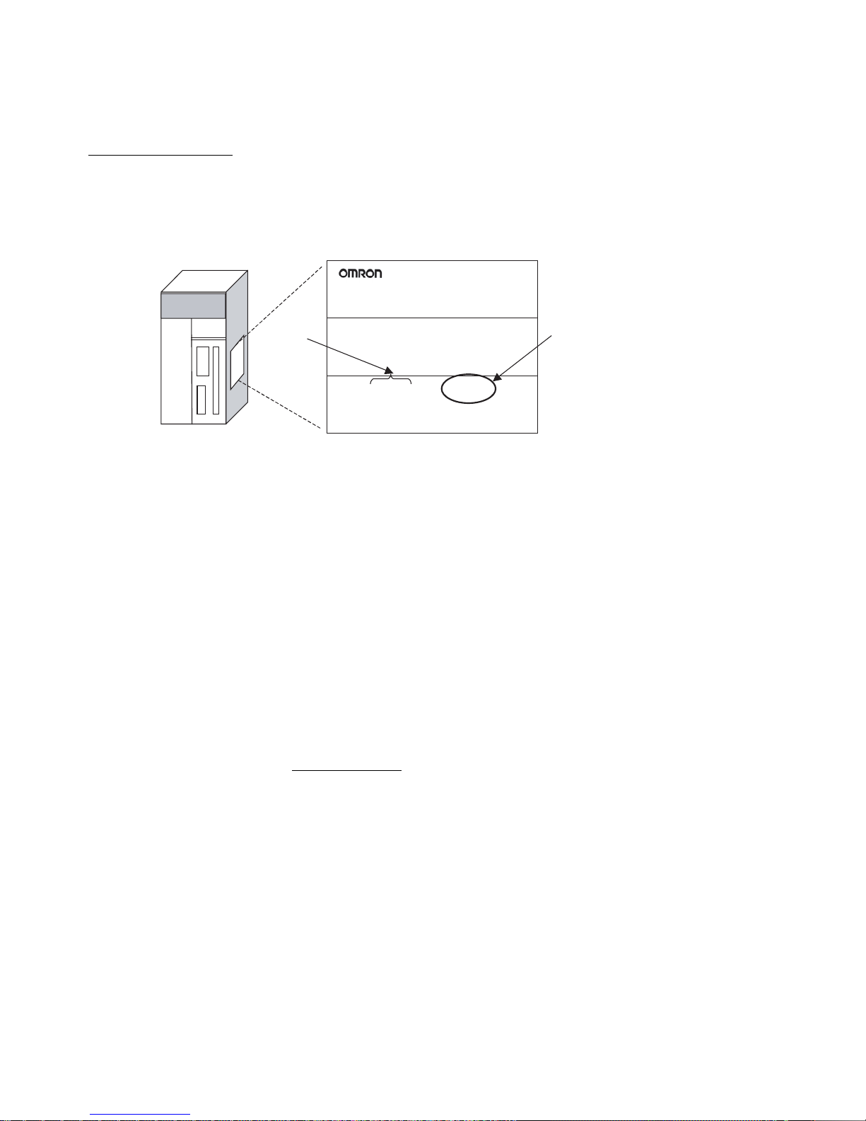
Notation of Unit Versions
on Products
The unit version is given to the right of the lot number on the nameplate of the
products for which unit versions are being managed, as shown below.
• CS1-H, CJ1-H, and CJ1M CPU Units manufactured on or before November 4, 2003 do not have a unit version given on the CPU Unit (i.e., the
location for the unit version shown above is blank).
• The unit version of the CJ1-H-R CPU Units begins at version 4.0.
• The unit version of the CS1-H, CJ1-H, and CJ1M CPU Units, as well as
the CS1D CPU Units for Single-CPU Systems, begins at version 2.0.
• The unit version of the CS1D CPU Units for Duplex-CPU Systems, begins
at version 1.1.
• CPU Units for which a unit version is not given are called Pre-Ver. @.@
CPU Units, such as Pre-Ver. 2.0 CPU Units and Pre-Ver. 1.1 CPU Units.
Confirming Unit Versions
with Support Software
CX-Programmer version 4.0 can be used to confirm the unit version using one
of the following two methods.
• Using the PLC Information
• Using the Unit Manufacturing Information (This method can be used for
Special I/O Units and CPU Bus Units as well.)
Note CX-Programmer version 3.3 or lower cannot be used to confirm unit versions.
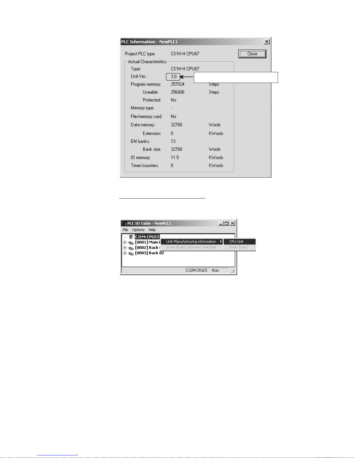
PLC Information
• If you know the device type and CPU type, select them in the Change
PLC Dialog Box, go online, and select PLC - Edit - Information from the
menus.
• If you don't know the device type and CPU type, but are connected
directly to the CPU Unit on a serial line, select PLC - Auto Online to go
online, and then select PLC - Edit - Information from the menus.
In either case, the following PLC Information Dialog Box will be displayed.
CS1H-CPU67H
CPU UNIT
Lot No. 040715 0000 Ver.3.0
OMRON Corporation MADE IN JAPAN
CS/CJ-series CPU Unit
Product nameplate
Lot No.
Unit version
Example for Unit version 3.0
Page 7
vii
Use the above display to confirm the unit version of the CPU Unit.
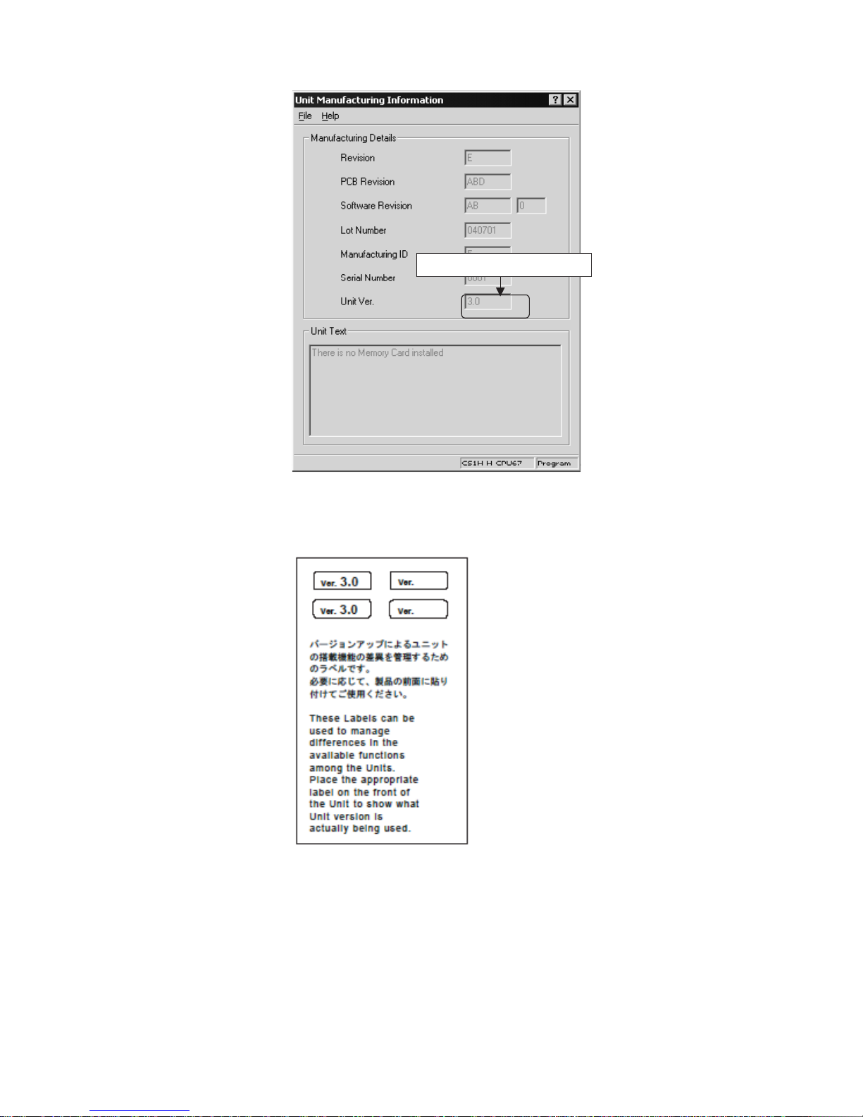
Unit Manufacturing Information
In the IO Table Window, right-click and select Unit Manufacturing information - CPU Unit.
The following Unit Manufacturing information Dialog Box will be displayed.
Unit version
Page 8
viii
Use the above display to confirm the unit version of the CPU Unit connected
online.
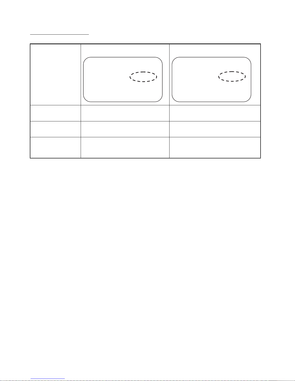
Using the Unit Version
Labels
The following unit version labels are provided with the CPU Unit.
These labels can be attached to the front of previous CPU Units to differentiate between CPU Units of different unit versions.
Unit version
Page 9
ix
Unit Version Notation In this manual, the unit version of a CPU Unit is given as shown in the follow-
ing table.
Product nameplate
Meaning
CPU Units on which no unit version is
given
Units on which a version is given
(Ver. @.@)
Designating individual
CPU Units (e.g., the
CS1H-CPU67H)
Pre-Ver. 2.0 CS1-H CPU Units CS1H-CPU67H CPU Unit Ver. @.@
Designating groups of
CPU Units (e.g., the
CS1-H CPU Units)
Pre-Ver. 2.0 CS1-H CPU Units CS1-H CPU Units Ver. @.@
Designating an entire
series of CPU Units
(e.g., the CS-series CPU
Units)
Pre-Ver. 2.0 CS-series CPU Units CS-series CPU Units Ver. @.@
Lot No. XXXXXX XXXX
OMRON Corporation MADE IN JAPAN
Lot No. XXXXXX XXXX
Ver. @ @ .@
Page 10

x
Unit Versions
CJ Series
NSJ Series
Units Models Unit version
CJ1-H CPU Units CJ1H-CPU@@H-R Unit version 4.2
Unit version 4.1
Unit version 4.0
CJ1@-CPU@@H
CJ1@-CPU@@P
Unit version 4.0
Unit version 3.0
Unit version 2.0
Pre-Ver. 2.0
CJ1M CPU Units
CJ1M-CPU12/13
CJ1M-CPU22/23
Unit version 4.0
Unit version 3.0
Unit version 2.0
Pre-Ver. 2.0
CJ1M-CPU11/21 Unit version 4.0
Unit version 3.0
Unit version 2.0
Units Unit version
NSJ@-TQ@@(B)-G5D
NSJ@-TQ@@(B)-M3D
Unit version 3.0
Page 11

xi
Function Support by Unit Version
• Functions Supported for Unit Version 4.0 or Later
CX-Programmer 7.0 or higher must be used to enable using the functions
added for unit version 4.0.
Additional functions are supported if CX-Programmer version 7.2 or higher is
used.
CJ1-H/CJ1M CPU Units
User programs that contain functions supported only by CPU Units with unit
version 4.0 or later cannot be used on CS/CJ-series CPU Units with unit version 3.0 or earlier. An error message will be displayed if an attempt is made to
download programs containing unit version 4.0 functions to a CPU Unit with a
unit version of 3.0 or earlier, and the download will not be possible.
If an object program file (.OBJ) using these functions is transferred to a CPU
Unit with a unit version of 3.0 or earlier, a program error will occur when operation is started or when the unit version 4.0 function is executed, and CPU
Unit operation will stop.
Function CJ1H-CPU@@H-R, CJ1@-CPU@@H,
CJ1G-CPU@@P, C J1 M - C P U @@
Unit version 4.0 or
later
Other unit versions
Online editing of function blocks
Note This function cannot be used for simulations on the
CX-Simulator.
OK ---
Input-output variables in function blocks OK --Text strings in function blocks OK ---
New application
instructions
Number-Text String Conversion Instructions:
NUM4, NUM8, NUM16, STR4, STR8, and STR16
OK ---
TEXT FILE WRITE (TWRIT) OK ---
ST programming in task programs OK with CX-Program-
mer version 7.2 or
higher
---
SFC programming in task programs OK with CX-Program-
mer version 7.2 or
higher
---
Page 12

xii
• Functions Supported for Unit Version 3.0 or Later
CX-Programmer 5.0 or higher must be used to enable using the functions
added for unit version 3.0.
CJ1-H/CJ1M CPU Units
User programs that contain functions supported only by CPU Units with unit
version 3.0 or later cannot be used on CS/CJ-series CPU Units with unit version 2.0 or earlier. An error message will be displayed if an attempt is made to
download programs containing unit version 3.0 functions to a CPU Unit with a
unit version of 2.0 or earlier, and the download will not be possible.
If an object program file (.OBJ) using these functions is transferred to a CPU
Unit with a unit version of 2.0 or earlier, a program error will occur when operation is started or when the unit version 3.0 function is executed, and CPU
Unit operation will stop.
Function CJ1H-CPU@@H-R
CJ1@-CPU@@H,
CJ1G-CPU@@P,
CJ1M-CPU@@
Unit version 3.0 or
later
Other unit versions
Function blocks OK --Serial Gateway (converting FINS commands to CompoWay/F
commands at the built-in serial port)
OK ---
Comment memory (in internal flash memory) OK --Expanded simple backup data OK --New application
instructions
TXDU(256), RXDU(255) (support no-protocol
communications with Serial Communications
Units with unit version 1.2 or later)
OK ---
Model conversion instructions: XFERC(565),
DISTC(566), COLLC(567), MOVBC(568),
BCNTC(621)
OK ---
Special function block instructions: GETID(286) OK ---
Additional
instruction functions
PRV(881) and PRV2(883) instructions: Added
high-frequency calculation methods for calculating pulse frequency. (CJ1M CPU Units only)
OK ---
Page 13

xiii
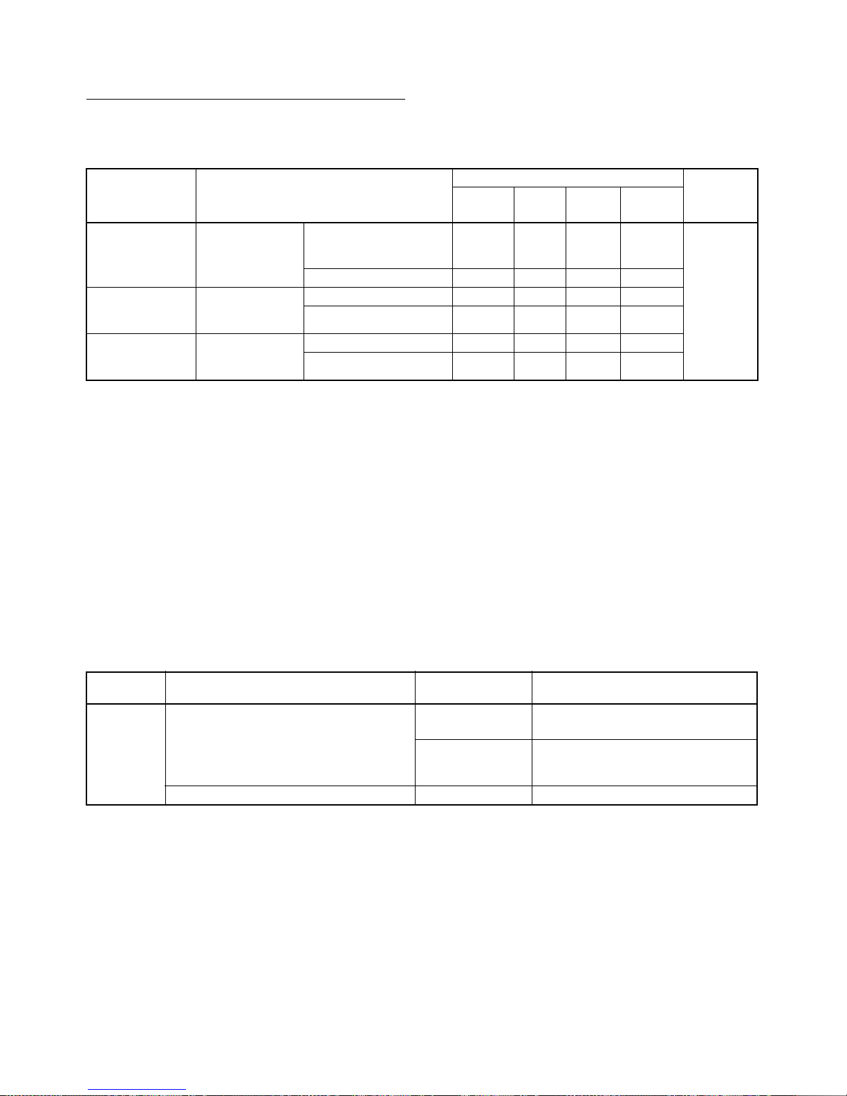
• Functions Supported for Unit Version 2.0 or Later
CX-Programmer 4.0 or higher must be used to enable using the functions
added for unit version 2.0.
CJ1-H/CJ1M CPU Units
Function
CJ1-H CPU Units CJ1M CPU Units
(CJ1H-CPU@@H-R)
(CJ1@-CPU@@H)
(CJ1G-CPU@@P)
CJ1M-CPU12/13/22/23 CJ1M-
CPU11/21
Unit version
2.0 or
later
Other unit
versions
Unit version
2.0 or
later
Other unit
versions
Other unit
version 2.0
or later
Downloading and Uploading Individual Tasks OK --- OK --- OK
Improved Read Protection Using Passwords OK --- OK --- OK
Write Protection from FINS Commands Sent
to CPU Units via Networks
OK --- OK --- OK
Online Network Connections without I/O
Ta bl e s
OK --- (Sup-
ported if I/O
tables are
automatically
generated at
startup.)
OK --- (Sup-
ported if I/O
tables are
automatically
generated at
startup.)
OK
Communications through a Maximum of 8
Network Levels
OK --- OK --- OK
Connecting Online to PLCs via NS-series
PTs
OK OK from lot
number
030201
OK OK from lot
number
030201
OK
Setting First Slot Words OK for up to
64 groups
OK for up to 8
groups
OK for up to
64 groups
OK for up to 8
groups
OK for up to
64 groups
Automatic Transfers at Power ON without a
Parameter File
OK --- OK --- OK
Automatic Detection of I/O Allocation Method
for Automatic Transfer at Power ON
OK --- OK --- OK
Operation Start/End Times OK --- OK --- OK
New Applica-
tion Instructions
MILH, MILR, MILC OK --- OK --- OK
=DT, <>DT, <DT, <=DT,
>DT, >=DT
OK --- OK --- OK
BCMP2 OK --- OK OK OK
GRY OK OK from lot
number
030201
OK OK from lot
number
030201
OK
TPO OK --- OK --- OK
D S W, T K Y, H KY, MT R ,
7SEG
OK --- OK --- OK
EXPLT, EGATR, ESATR,
ECHRD, ECHWR
OK --- OK --- OK
Reading/Writing CPU Bus
Units with IORD/IOWR
OK --- OK --- OK
PRV2 --- --- OK, but only
for CPU Units
with built-in
I/O
--- OK, but only
for CPU Units
with built-in
I/O
Page 14

xiv
User programs that contain functions supported only by CPU Units with unit
version 2.0 or later cannot be used on CS/CJ-series Pre-Ver. 2.0 CPU Units.
An error message will be displayed if an attempt is made to download programs containing unit version s.0 functions to a Pre-Ver. 2.0 CPU Unit, and
the download will not be possible.
If an object program file (.OBJ) using these functions is transferred to a PreVer. 2.0 CPU Unit, a program error will occur when operation is started or
when the unit version 2.0 function is executed, and CPU Unit operation will
stop.
Page 15
xv
Unit Versions and Programming Devices
The following tables show the relationship between unit versions and CX-Programmer versions.
Unit Versions and Programming Devices
Note 1. As shown above, there is no need to upgrade to CX-Programmer version
as long as the functions added for unit versions are not used.
2. CX-Programmer version 7.1 or higher is required to use the new functions
added for unit version 4.0 of the CJ1-H-R CPU Units. CX-Programmer version 7.22 or higher is required to use unit version 4.1 of the CJ1-H-R CPU
Units. CX-Programmer version 7.0 or higher is required to use unit version
4.2 of the CJ1-H-R CPU Units. You can check the CX-Programmer version
using the About menu command to display version information.
3. CX-Programmer version 7.0 or higher is required to use the functional improvements made for unit version 4.0 of the CS/CJ-series CPU Units. With
CX-Programmer version 7.2 or higher, you can use even more expanded
functionality.
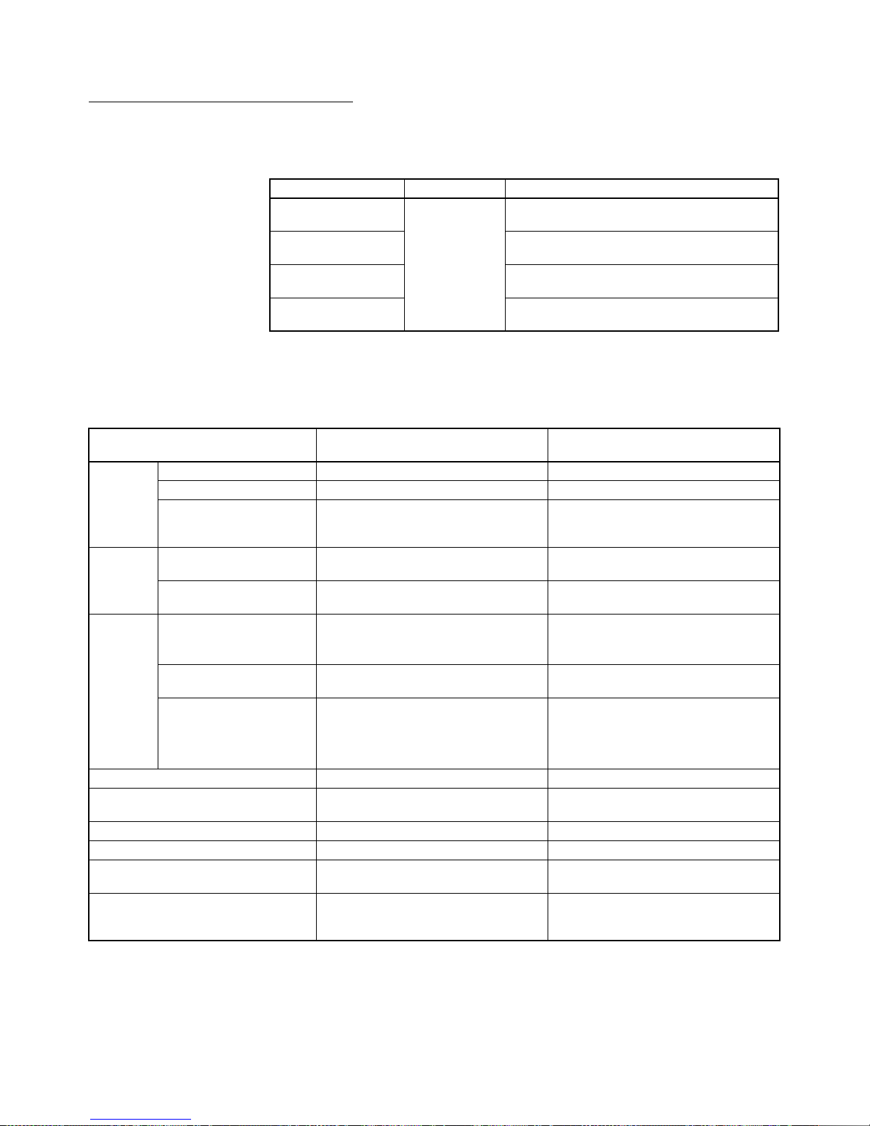
Device Type Setting The unit version does not affect the setting made for the device type on the
CX-Programmer. Select the device type as shown in the following table
regardless of the unit version of the CPU Unit.
Note Select one of the following CPU types: CPU67-R, CPU66-R, CPU65-R, or
CPU64-R.
CPU Unit Functions (See note 1.) CX-Programmer Program-
ming Con-
sole
Ver. 3.3
or lower
Ver. 4.0 Ver. 5.0
Ver. 6.0
Ver. 7.0
or higher
CS/CJ-series unit
version 4.0
Functions added
for unit version
4.0
Using new functions --- --- --- OK (See
notes 2
and 3.)
No
restrictions
Not using new functions OK OK OK OK
CS/CJ-series unit
version 3.0
Functions added
for unit version
3.0
Using new functions --- --- OK OK
Not using new functions OK OK OK OK
CS/CJ-series unit
version 2.0
Functions added
for unit version
2.0
Using new functions --- OK OK OK
Not using new functions OK OK OK OK
Series CPU Unit group CPU Unit model Device type setting on
CX-Programmer Ver. 4.0 or higher
CJ Series CJ1-H CPU Units CJ1G-CPU@@H
CJ1G-CPU@@P
CJ1G-H
CJ1H-CPU@@H-R
(See note.)
CJ1H-CPU@@H
CJ1H-H
CJ1M CPU Units CJ1M-CPU@@ CJ1M
Page 16
xvi
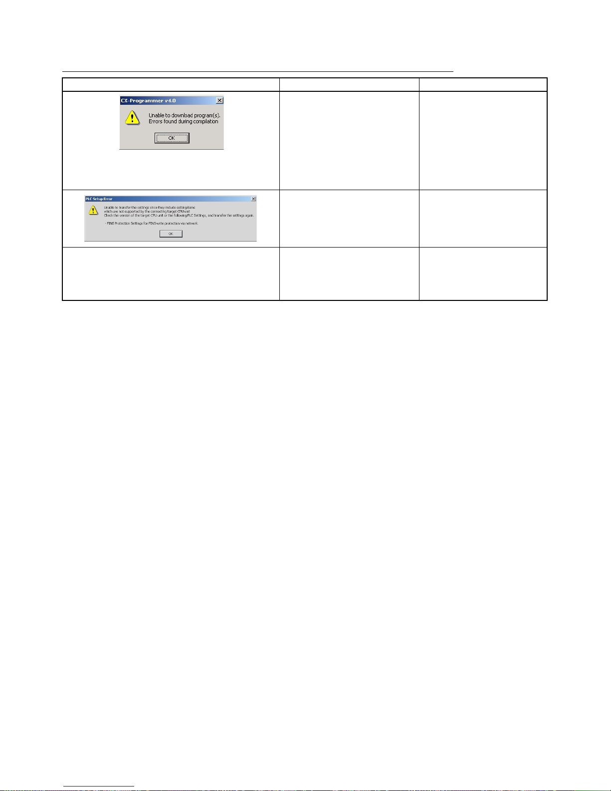
Troubleshooting Problems with Unit Versions on the CX-Programmer
Problem Cause Solution
After the above message is displayed, a compiling
error will be displayed on the Compile Tab Page in the
Output Window.
An attempt was made to download a program containing
instructions supported only by
later unit versions or a CPU Unit
to a previous unit version.
Check the program or change
to a CPU Unit with a later unit
version.
An attempt was to download a
PLC Setup containing settings
supported only by later unit versions or a CPU Unit to a previous
unit version.
Check the settings in the PLC
Setup or change to a CPU Unit
with a later unit version.
“????” is displayed in a program transferred from the
PLC to the CX-Programmer.
An attempt was made to upload a
program containing instructions
supported only by higher versions
of CX-Programmer to a lower version.
New instructions cannot be
uploaded to lower versions of
CX-Programmer. Use a higher
version of CX-Programmer.
Page 17
xvii
CJ1-H-R CPU Units (High-speed)
Overview The CJ1-H-R CPU Units (CJ1H-CPU@@H-R) are high-speed versions of unit
version 4.0 of the CJ1-H CPU Units (CJ1H-CPU@@H).
Models
Note In the CX-Programmer, set the device type to CJ1H-H and the CPU type to
CPU67-R, CPU66-R, CPU65-R, or CPU64-R.
Differences Compared to
CJ1-H CPU Units
The CJ1-H-R CPU Units (CJ1H-CPU@@H-R) have the following differences
in comparison to the CJ1-H CPU Units (CJ1H-CPU@@H).
Note 1. Refer to the CX-Integrator Operation Manual (Cat. No. W445) and the
Communication Unit operation manuals for details.
2. The 0.01 s Clock Pulse cannot be used with unit version 4.1 of the CJ1-HR
CPU Units. The 0.01 s Clock Pulse can be used with all other unit versions.
Model Unit version Specifications
CJ1H-CPU67H-R Ver. 4.2 Equivalent to CJ1H-CPU67H
(Program capacity: 250K steps)
CJ1H-CPU66H-R Equivalent to CJ1H-CPU66H
(Program capacity: 120K steps)
CJ1H-CPU65H-R Equivalent to CJ1H-CPU65H
(Program capacity: 60K steps)
CJ1H-CPU64H-R Equivalent to CJ1H-CPU64H
(Program capacity: 30K steps)
Item CJ1-H-R CPU Units
(CJ1H-CPU@@H-R)
CJ1-H CPU Units
(CJ1H-CPU@@H)
Instruction execution
time
Basic instructions 0.016 µs min. 0.02 µs min.
Special instructions 0.048 µs min. 0.06 µs min.
Floating-point math calcu-
lations (e.g., FLOATINGPOINT ADD (+F(454))
0.24 µs8 µs
I/O
refreshing
Basic I/O Units (e.g., 16point Input Unit)
1.4 µs3 µs
Special I/O Units (e.g.,
Analog Input Unit)
50 µs 120 µs
New
instructions
Timer instructions • TENTH-MS TIMER (TIMU/TIMUX)
• HUNDREDTH-MS TIMER
(TIMUH/TMUHX)
Not supported.
I/O Unit Instructions • SPECIAL I/O UNIT I/O REFRESH
(FIORF(225))
Not supported.
Floating-point math and
conversion instructions
• SINQ
• COSQ
• TAN Q
• MOVF
Not supported.
Overhead processing time 0.13 ms 0.3 ms
Unit for setting scheduled interrupt
intervals
0.1, 1, or 10 ms 1 or 10 ms
Software interval response time 40 µs 124 µs
Function block startup time 3.3 µs6.8 µs
Clock pulses 0.1 ms, 1 ms, 0.01 s (See note 2.),
0.02 s, 0.1 s, 0.2 s, 1 s, 1 min
0.02 s, 0.1 s, 0.2 s, 1 s, 1 min
Maximum number of relay networks
that can be set in routing tables
(See note 1.)
64 20
Page 18
xviii
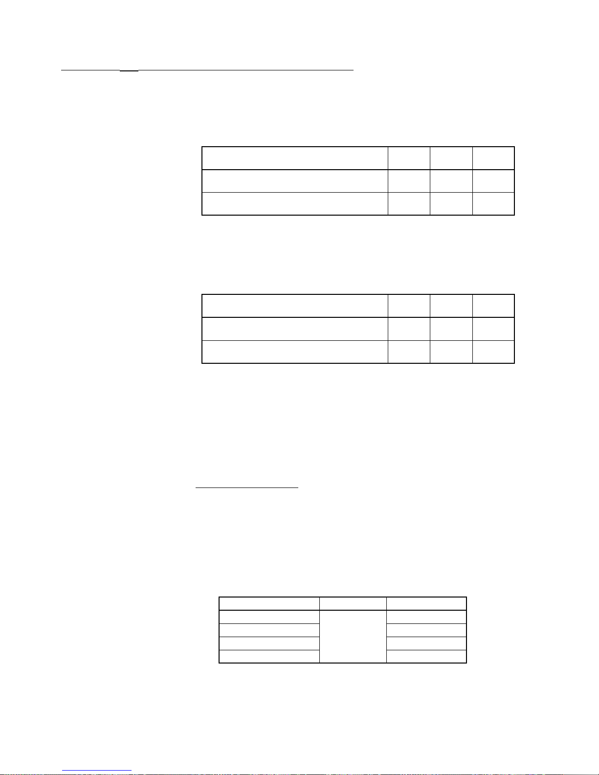
CJ1H-CPU@@H-R Version 4.1 Specifications Change
The following specifications changes have been made for CJ1H-CPU@@H-R
version 4.1.
The following specifications for unit version 4.2 and later are the same as the
specifications for unit version 4.0.
Functionality Changes
• If ONE-MS TIMER instructions (TMHH(540)/TMHHX(552)) with timer
numbers 0 to 15 are used in existing programs with CJ1H-CPU@@H-R
version 4.1, the timer numbers must be changed to timer numbers
between 0016 and 4095.
Performance Changes
Note 1. The timing precision of version 4.0 and version 4.1 are different. Be sure
to check the effect on the application.
2. There have been no changes in the timing precision of TEN-MS TIMER instructions (TIMH(015)/TIMHX(551)) and TENTH-MS TIMER instructions
(TIMU(541)/TIMUX(556)) since version 4.0. Use TEN-MS TIMER instructions and TENTH-MS TIMER instructions if accuracy is a problem when
using HUNDRED-MS TIMER instructions and ONE-MS TIMER instructions.
■ Programming Devices
Use CX-Programmer version 7.1 or higher for the CJ1-H-R CPU Units. Set
the device type to CJ1H-H and the CPU type to one of the CPU types ending
in “-R.” Use the following procedure.
1,2,3... 1. Select New from the File Menu.
2. Select CJ1H-H in the Change PLC Dialog Box.
3. Select one of the following for the CPU type: CPU67-R, CPU66-R, CPU65R, or CPU64-R.
Note 1. If CX-Programmer version 7.0 or lower is used, the new features of the
CJ1-H-R CPU Units will not be supported, i.e., functionality will be the
same as the CJ1-H CPU Units.
CPU Unit version CJ1-H
Ver. 4. 0
CJ1-H-R
Ver. 4. 0
CJ1-H-R
Ver. 4. 1
Timer numbers that can be used with ONE-MS
TIMER instructions
0000 to
0015
0000 to
4095
0016 to
4095
0.01-s clock pulse Not supported
Supported
Not supported
CPU Unit version CJ1-H
Ver. 4. 0
CJ1-H-R
Ver. 4. 0
CJ1-H-R
Ver. 4. 1
Timing precision of HUNDRED-MS TIMER
instructions (TIM/TIMX(550))
−10 to
0ms
−10 to
0ms
−100 to
0ms
Timing precision of ONE-MS TIMER instructions (TMHH(540)/TMHHX(522))
−1 to
0ms
−1 to
0ms
−10 to
0ms
Model Device type CPU type
CJ1H-CPU67H-R CJ1H-H CPU67-R
CJ1H-CPU66H-R CPU66-R
CJ1H-CPU65H-R CPU65-R
CJ1H-CPU64H-R CPU64-R
Page 19

xix
2. CX-Programmer version 7.22 or higher is required to use unit version 4.1
of the CJ1-H-R CPU Units. CX-Programmer version 7.0 or higher is required to use unit version 4.2 of the CJ1-H-R CPU Units. CX-Programmer
version 7.22 or higher has added functionality that will provide a warning
when performing a program check or when transferring the program if a
ONE-MS TIMER instruction ((TMHH(540)/TMHHX(552)) is set to timer
numbers 0000 to 0015 or if a 0.01-second clock pulse is used. Version 7.22
or higher can be obtained using the auto-update function. If you are not
sure how to obtain CX-Programmer version 7.22, contact your OMRON
representative.
Page 20
xx
Loop-control CPU Units
Overview Loop-control CPU Units are CPU Units with a pre-installed Loop Controller
functional element.
Note The Loop Controller functional element is an inseparable part of the CPU Unit
and cannot be removed.
Model Numbers,
Functional Elements,
and Versions
The CJ1G-CPU@@P Loop-control CPU Unit is comprised of a CPU Unit element with the same functionality as a CJ1G-CPU@@H CPU Unit with version
3.0 or later (see note) and a Loop Controller element. The following table lists
the model numbers for CJ1G Loop-control CPU Units, the types of CPU Unit
element, Loop Controller element, and the functional element version codes.
Note A single unit version for the Loop-control CPU Unit as a whole is not provided.
The unit versions for the CJ1-H CPU Unit with unit version 3.0 or later and the
functional element version code.
Differences between
CJ1G-CPU@@H and
CPU Unit Elements
The differences between the CPU Unit element in the Loop-control CPU Unit
and the CJ1G-CPU@@H CPU Unit are shown here. The two types of CPU
Unit are otherwise the same.
Note The functions added in the version upgrade for unit version 3.0 and later are
also the same.
Additional Auxiliary Area
Flags and Bits
Loop-control CPU Units can use the following Auxiliary Area flags and bits,
which are not supported for CJ1G-CPU@@H CPU Units.
For details on the Auxiliary Area bits and flags, refer to the section on SYS-
MAC CS/CJ Series Loop Control Boards, Process-control CPU Units, Loopcontrol CPU Units Operation Manual (W406).
Product name Product model
number
Configuration
CPU Unit element Loop Controller element
CPU Unit model
with same function-
ality
Functional ele-
ment unit ver-
sion
Functional ele-
ment name
Functional ele-
ment version
Loop-control
CPU Units
CJ1G-CPU45P CJ1G-CPU45H Ver. 3.0 or higher LCB03 Ver. 2.0
CJ1G-CPU44P CJ1G-CPU44H Ver. 3.0 or higher LCB03 Ver. 2.0
CJ1G-CPU43P CJ1G-CPU43H Ver. 3.0 or higher LCB03 Ver. 2.0
CJ1G-CPU42P CJ1G-CPU42H Ver. 3.0 or higher LCB01 Ver. 2.0
Address Name
Word B it
A424 00 Inner Board WDT Error Flag (fatal error)
01 Inner Board Bus Error Flag (fatal error)
02 Cyclic Monitor Error Flag (fatal error)
03 Flash Memory Data Error Flag (fatal error)
04 Incompatible CPU Unit Error Flag (non-fatal error)
08 Loop Controller High Load Flag (non-fatal error)
11 Backup Data (Flash Memory) Error Flag
12 Specified EM Bank Unusable Error Flag
A608 00 Inner Board Restart Bit
A609 01 Start Mode at Power ON: Hot Start
A609 02 Start Mode at Power ON: Cold Start
Page 21
xxi
Loop-control CPU Unit
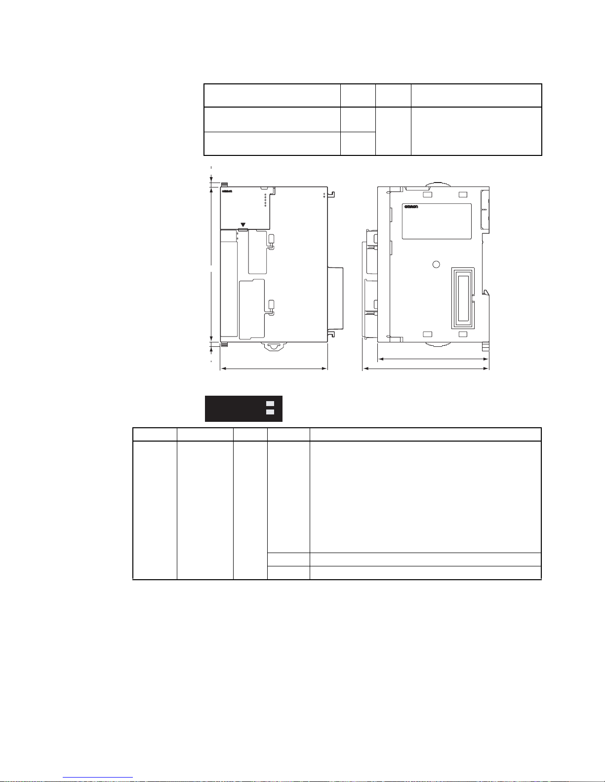
Dimensions
Indicators
Product name and model W
(mm)H (mm)
D (mm)
CJ1G-CPU45P/44P/43P/42P
Loop-control CPU Unit
69 90 65 (not including connector)
73.9 (including connector)
CJ1G-CPU45H/44H/43H/42H
CJ1-H CPU Unit (reference)
62
CONTROLLER
CJ1G-CPU44P
SYSMAC
PROGRAMMABLE
ERR/ALM
RUN
COMM
INH
PRPHL
OPEN
PERIPHERAL
BUSY
MCPWR
PORT
65
69 73.9
2.7
2.7
90
LCB03
EXEC
RDY
INNER LOOP CONTROLLER
RDY
EXEC
Indicator Name Color Status Description
RDY Ready Green Not lit The Loop Control Board is not operating for one of the fol-
lowing reasons:
• A Fatal Inner Board Error occurred (A40112 ON.)
• Initialization is not completed yet.
• A fatal error occurred.
• The flash memory backup data is invalid.
• The Loop Control Board is initializing.
• A hardware failure occurred in the Loop Control Board.
• Power is not being supplied from the Power Supply Unit.
• A Loop Control Board WDT error occurred.
Flashing • A WDT error occurred in the CPU Unit.
Lit The Loop Control Board is ready for operation.
Page 22

xxii
Current Consumption and
Weight
Common Processing Time
(Overhead Time)
Battery Backup Time At 25°C, the battery life (maximum service life) for batteries is five years
whether or not power is supplied to the CPU Unit while the battery is installed.
This is the same as for CJ1G-CPU@@H CPU Units. The following table shows
the approximate minimum lifetimes and typical lifetimes for the backup battery
(total time with power not supplied).
Note The minimum lifetime is the memory backup time at an ambient temperature
of 55°C. The typical lifetime is the memory backup time at an ambient temperature of 25°C.
EXEC Running Green Not lit The system is stopped for one of the following reasons:
• The Loop Control Board is initializing.
• A hardware failure occurred in the Loop Control Board.
• Power is not being supplied from the Power Supply Unit.
• A Loop Control Board WDT error occurred.
• The Loop Control Board is not running.
• Data is being written to flash memory.
Flashing
(at 0.5-s
intervals)
Erasing flash memory.
Flashing
(0.2-s
intervals)
Backup operation to function block flash memory in
progress
Lit The Loop Control Board is not running.
Indicator Name Color Status Description
Product name and model Current consumption Weight
CJ1G-CPU45P/44P/43P/42P
Loop-control CPU Unit
1.06 A 220 g max.
CJ1G-CPU45H/44H/43H/42H
CJ1-H CPU Unit (reference)
0.91 A 190 g max.
Product name and model Common processing time
CJ1G-CPU45P/44P/43P/42P
Loop-control CPU Unit
0.8 ms max.
CJ1G-CPU45H/44H/43H/42H
CJ1-H CPU Unit (reference)
0.3 ms
Model Approx.
maximum
lifetime
Approx.
minimum
lifetime
(See note.)
Typica l lifetime
(See note.)
CJ1G-CPU45P/44P/43P/42P
Loop-control CPU Unit
5 years 5,600 hours
(approximately
0.64 years)
43,000 hours
(approximately
5 years)
CJ1G-CPU45H/44H/43H/42H
CJ1-H CPU Unit (reference)
5 years 6,500 hours
(approximately
0.75 years)
43,000 hours
(approximately
5 years)
Page 23

xxiii
Programming Devices
Loop Controller Element Using CX-Process Tool Ver. 4.0 or later, select the Loop-control CPU
Unit/Process-control CPU Unit from the LC Type field in the LCB/LC001 Dia-
log Box. Then select either CJ1G-CPU42P, CJ1G-CPU43P, CJ1G-CPU44P,
orCJ1G-CPU45P, from the Number-Model pull-down list in the Unit Informa-
tion field.
CPU Unit Element Use CX-Programmer Ver. 5.0 or later. The CPU Unit functions are the same
as the CJ1G-CPU@@H, except for the differences provided in the previous
table. Therefore, select CJ1G-H as the device type when using CX-Programmer.
1,2,3... 1. Select New from the File Menu.
2. Select one of the following CPU Unit types in the Change PLC Dialog Box.
Reference Manuals • The CPU Unit functions are the same as the CJ1G-CPU@@H, except for
the differences provided in the previous table. Therefore, for details on the
CPU Unit functions, refer to the SYSMAC CJ Series Programmable Con-
trollers Operation Manual (W393), SYSMAC CS/CJ Series Programmable
Controllers Programming Manual (W394), SYSMAC CS/CJ Series Programmable Controllers Instructions Reference Manual (W340), and Communications Commands Reference Manual (W342).
• For details on the Loop Controller functions (LCB@@ functional element)
refer to the section on SYSMAC CS/CJ Series Loop Control Boards, Pro-
cess-control CPU Units, Loop-control CPU Units Operation Manual
(W406).
Loop-control CPU Unit Device type CPU Unit type
CJ1G-CPU45P CJ1G-H CPU45
CJ1G-CPU44P CPU44
CJ1G-CPU43P CPU43
CJ1G-CPU42P CPU42
Page 24

xxiv
Page 25

xxv
TABLE OF CONTENTS
PRECAUTIONS . . . . . . . . . . . . . . . . . . . . . . . . . . . . . . . . . . .xxxvii
1 Intended Audience . . . . . . . . . . . . . . . . . . . . . . . . . . . . . . . . . . . . . . . . . . . . . . . . . . . . . . . . xxxviii
2 General Precautions . . . . . . . . . . . . . . . . . . . . . . . . . . . . . . . . . . . . . . . . . . . . . . . . . . . . . . . xxxviii
3 Safety Precautions . . . . . . . . . . . . . . . . . . . . . . . . . . . . . . . . . . . . . . . . . . . . . . . . . . . . . . . . . xxxviii
4 Operating Environment Precautions . . . . . . . . . . . . . . . . . . . . . . . . . . . . . . . . . . . . . . . . . . . xl
5 Application Precautions . . . . . . . . . . . . . . . . . . . . . . . . . . . . . . . . . . . . . . . . . . . . . . . . . . . .xli
6 Conformance to EC Directives . . . . . . . . . . . . . . . . . . . . . . . . . . . . . . . . . . . . . . . . . . . . . . . xlv
SECTION 1
Introduction . . . . . . . . . . . . . . . . . . . . . . . . . . . . . . . . . . . . . . 1
1-1 Overview . . . . . . . . . . . . . . . . . . . . . . . . . . . . . . . . . . . . . . . . . . . . . . . . . . . . . . . . . . . . . . . . 2
1-2 CJ-series Features . . . . . . . . . . . . . . . . . . . . . . . . . . . . . . . . . . . . . . . . . . . . . . . . . . . . . . . . . 3
1-3 CJ1-H and CJ1M CPU Unit Features . . . . . . . . . . . . . . . . . . . . . . . . . . . . . . . . . . . . . . . . . . 13
1-4 CJ1-H/CJ1M CPU Unit Ver. 4.0 Upgrades. . . . . . . . . . . . . . . . . . . . . . . . . . . . . . . . . . . . . . 25
1-5 CJ1-H/CJ1M CPU Unit Ver. 3.0 Upgrades. . . . . . . . . . . . . . . . . . . . . . . . . . . . . . . . . . . . . . 26
1-6 CJ1-H/CJ1M CPU Unit Ver. 2.0 Upgrades. . . . . . . . . . . . . . . . . . . . . . . . . . . . . . . . . . . . . . 31
1-7 CJ1-H-R, CJ1-H, CJ1M, and CJ1 CPU Unit Comparison . . . . . . . . . . . . . . . . . . . . . . . . . . 54
1-8 Function Tables . . . . . . . . . . . . . . . . . . . . . . . . . . . . . . . . . . . . . . . . . . . . . . . . . . . . . . . . . . . 58
1-9 CJ1M Functions Arranged by Purpose . . . . . . . . . . . . . . . . . . . . . . . . . . . . . . . . . . . . . . . . . 67
1-10 Comparison to CS-series PLCs. . . . . . . . . . . . . . . . . . . . . . . . . . . . . . . . . . . . . . . . . . . . . . . 73
SECTION 2
Specifications and System Configuration. . . . . . . . . . . . . . . 75
2-1 Specifications . . . . . . . . . . . . . . . . . . . . . . . . . . . . . . . . . . . . . . . . . . . . . . . . . . . . . . . . . . . . 76
2-2 CPU Unit Components and Functions . . . . . . . . . . . . . . . . . . . . . . . . . . . . . . . . . . . . . . . . . 90
2-3 Basic System Configuration . . . . . . . . . . . . . . . . . . . . . . . . . . . . . . . . . . . . . . . . . . . . . . . . . 94
2-4 I/O Units . . . . . . . . . . . . . . . . . . . . . . . . . . . . . . . . . . . . . . . . . . . . . . . . . . . . . . . . . . . . . . . . 106
2-5 Expanded System Configuration. . . . . . . . . . . . . . . . . . . . . . . . . . . . . . . . . . . . . . . . . . . . . . 112
2-6 Unit Current Consumption . . . . . . . . . . . . . . . . . . . . . . . . . . . . . . . . . . . . . . . . . . . . . . . . . . 129
2-7 CPU Bus Unit Setting Area Capacity . . . . . . . . . . . . . . . . . . . . . . . . . . . . . . . . . . . . . . . . . . 134
2-8 I/O Table Settings List . . . . . . . . . . . . . . . . . . . . . . . . . . . . . . . . . . . . . . . . . . . . . . . . . . . . . 135
SECTION 3
Nomenclature, Functions, and Dimensions . . . . . . . . . . . . . 139
3-1 CPU Units . . . . . . . . . . . . . . . . . . . . . . . . . . . . . . . . . . . . . . . . . . . . . . . . . . . . . . . . . . . . . . . 140
3-2 File Memory . . . . . . . . . . . . . . . . . . . . . . . . . . . . . . . . . . . . . . . . . . . . . . . . . . . . . . . . . . . . . 149
3-3 Programming Devices. . . . . . . . . . . . . . . . . . . . . . . . . . . . . . . . . . . . . . . . . . . . . . . . . . . . . .158
3-4 Power Supply Units. . . . . . . . . . . . . . . . . . . . . . . . . . . . . . . . . . . . . . . . . . . . . . . . . . . . . . . . 170
3-5 I/O Control Units and I/O Interface Units. . . . . . . . . . . . . . . . . . . . . . . . . . . . . . . . . . . . . . . 181
3-6 CJ-series Basic I/O Units . . . . . . . . . . . . . . . . . . . . . . . . . . . . . . . . . . . . . . . . . . . . . . . . . . . 183
3-7 B7A Interface Unit . . . . . . . . . . . . . . . . . . . . . . . . . . . . . . . . . . . . . . . . . . . . . . . . . . . . . . . . 197
Page 26

xxvi
TABLE OF CONTENTS
SECTION 4
Operating Procedures . . . . . . . . . . . . . . . . . . . . . . . . . . . . . . 209
4-1 Introduction. . . . . . . . . . . . . . . . . . . . . . . . . . . . . . . . . . . . . . . . . . . . . . . . . . . . . . . . . . . . . . 210
4-2 Examples. . . . . . . . . . . . . . . . . . . . . . . . . . . . . . . . . . . . . . . . . . . . . . . . . . . . . . . . . . . . . . . . 212
SECTION 5
Installation and Wiring . . . . . . . . . . . . . . . . . . . . . . . . . . . . . 225
5-1 Fail-safe Circuits . . . . . . . . . . . . . . . . . . . . . . . . . . . . . . . . . . . . . . . . . . . . . . . . . . . . . . . . . . 226
5-2 Installation. . . . . . . . . . . . . . . . . . . . . . . . . . . . . . . . . . . . . . . . . . . . . . . . . . . . . . . . . . . . . . . 228
5-3 Wiring . . . . . . . . . . . . . . . . . . . . . . . . . . . . . . . . . . . . . . . . . . . . . . . . . . . . . . . . . . . . . . . . . . 255
SECTION 6
DIP Switch Settings . . . . . . . . . . . . . . . . . . . . . . . . . . . . . . . . 279
6-1 Overview. . . . . . . . . . . . . . . . . . . . . . . . . . . . . . . . . . . . . . . . . . . . . . . . . . . . . . . . . . . . . . . . 280
6-2 Details . . . . . . . . . . . . . . . . . . . . . . . . . . . . . . . . . . . . . . . . . . . . . . . . . . . . . . . . . . . . . . . . . . 281
SECTION 7
PLC Setup . . . . . . . . . . . . . . . . . . . . . . . . . . . . . . . . . . . . . . . . 285
7-1 PLC Setup . . . . . . . . . . . . . . . . . . . . . . . . . . . . . . . . . . . . . . . . . . . . . . . . . . . . . . . . . . . . . . . 286
7-2 Explanations of PLC Setup Settings . . . . . . . . . . . . . . . . . . . . . . . . . . . . . . . . . . . . . . . . . . . 333
SECTION 8
I/O Allocations . . . . . . . . . . . . . . . . . . . . . . . . . . . . . . . . . . . . 343
8-1 I/O Allocations . . . . . . . . . . . . . . . . . . . . . . . . . . . . . . . . . . . . . . . . . . . . . . . . . . . . . . . . . . . 344
8-2 Creating I/O Tables . . . . . . . . . . . . . . . . . . . . . . . . . . . . . . . . . . . . . . . . . . . . . . . . . . . . . . . . 350
8-3 Allocating First Words to Slots and Reserving Words . . . . . . . . . . . . . . . . . . . . . . . . . . . . . 355
8-4 Allocating First Words to Racks . . . . . . . . . . . . . . . . . . . . . . . . . . . . . . . . . . . . . . . . . . . . . . 358
8-5 Detailed Information on I/O Table Creation Errors . . . . . . . . . . . . . . . . . . . . . . . . . . . . . . . 361
8-6 Data Exchange with CPU Bus Units. . . . . . . . . . . . . . . . . . . . . . . . . . . . . . . . . . . . . . . . . . . 362
SECTION 9
Memory Areas . . . . . . . . . . . . . . . . . . . . . . . . . . . . . . . . . . . . 367
9-1 Introduction. . . . . . . . . . . . . . . . . . . . . . . . . . . . . . . . . . . . . . . . . . . . . . . . . . . . . . . . . . . . . . 368
9-2 I/O Memory Areas . . . . . . . . . . . . . . . . . . . . . . . . . . . . . . . . . . . . . . . . . . . . . . . . . . . . . . . . 369
9-3 I/O Area. . . . . . . . . . . . . . . . . . . . . . . . . . . . . . . . . . . . . . . . . . . . . . . . . . . . . . . . . . . . . . . . . 377
9-4 Data Link Area . . . . . . . . . . . . . . . . . . . . . . . . . . . . . . . . . . . . . . . . . . . . . . . . . . . . . . . . . . . 383
9-5 CPU Bus Unit Area. . . . . . . . . . . . . . . . . . . . . . . . . . . . . . . . . . . . . . . . . . . . . . . . . . . . . . . . 384
9-6 Special I/O Unit Area . . . . . . . . . . . . . . . . . . . . . . . . . . . . . . . . . . . . . . . . . . . . . . . . . . . . . . 386
9-7 Serial PLC Link Area . . . . . . . . . . . . . . . . . . . . . . . . . . . . . . . . . . . . . . . . . . . . . . . . . . . . . . 387
9-8 DeviceNet Area. . . . . . . . . . . . . . . . . . . . . . . . . . . . . . . . . . . . . . . . . . . . . . . . . . . . . . . . . . . 388
9-9 Internal I/O Area . . . . . . . . . . . . . . . . . . . . . . . . . . . . . . . . . . . . . . . . . . . . . . . . . . . . . . . . . . 389
9-10 Holding Area. . . . . . . . . . . . . . . . . . . . . . . . . . . . . . . . . . . . . . . . . . . . . . . . . . . . . . . . . . . . . 390
9-11 Auxiliary Area. . . . . . . . . . . . . . . . . . . . . . . . . . . . . . . . . . . . . . . . . . . . . . . . . . . . . . . . . . . . 391
Page 27

xxvii
TABLE OF CONTENTS
9-12 TR (Temporary Relay) Area . . . . . . . . . . . . . . . . . . . . . . . . . . . . . . . . . . . . . . . . . . . . . . . . . 422
9-13 Timer Area . . . . . . . . . . . . . . . . . . . . . . . . . . . . . . . . . . . . . . . . . . . . . . . . . . . . . . . . . . . . . . 423
9-14 Counter Area . . . . . . . . . . . . . . . . . . . . . . . . . . . . . . . . . . . . . . . . . . . . . . . . . . . . . . . . . . . . . 425
9-15 Data Memory (DM) Area . . . . . . . . . . . . . . . . . . . . . . . . . . . . . . . . . . . . . . . . . . . . . . . . . . . 425
9-16 Extended Data Memory (EM) Area . . . . . . . . . . . . . . . . . . . . . . . . . . . . . . . . . . . . . . . . . . . 427
9-17 Index Registers . . . . . . . . . . . . . . . . . . . . . . . . . . . . . . . . . . . . . . . . . . . . . . . . . . . . . . . . . . . 428
9-18 Data Registers . . . . . . . . . . . . . . . . . . . . . . . . . . . . . . . . . . . . . . . . . . . . . . . . . . . . . . . . . . . . 434
9-19 Task Flags . . . . . . . . . . . . . . . . . . . . . . . . . . . . . . . . . . . . . . . . . . . . . . . . . . . . . . . . . . . . . . . 435
9-20 Condition Flags . . . . . . . . . . . . . . . . . . . . . . . . . . . . . . . . . . . . . . . . . . . . . . . . . . . . . . . . . . . 436
9-21 Clock Pulses . . . . . . . . . . . . . . . . . . . . . . . . . . . . . . . . . . . . . . . . . . . . . . . . . . . . . . . . . . . . . 438
9-22 Parameter Areas . . . . . . . . . . . . . . . . . . . . . . . . . . . . . . . . . . . . . . . . . . . . . . . . . . . . . . . . . . 439
SECTION 10
CPU Unit Operation and the Cycle Time. . . . . . . . . . . . . . . 443
10-1 CPU Unit Operation . . . . . . . . . . . . . . . . . . . . . . . . . . . . . . . . . . . . . . . . . . . . . . . . . . . . . . . 445
10-2 CPU Unit Operating Modes . . . . . . . . . . . . . . . . . . . . . . . . . . . . . . . . . . . . . . . . . . . . . . . . . 449
10-3 Power OFF Operation . . . . . . . . . . . . . . . . . . . . . . . . . . . . . . . . . . . . . . . . . . . . . . . . . . . . . . 451
10-4 Computing the Cycle Time . . . . . . . . . . . . . . . . . . . . . . . . . . . . . . . . . . . . . . . . . . . . . . . . . . 457
10-5 Instruction Execution Times and Number of Steps . . . . . . . . . . . . . . . . . . . . . . . . . . . . . . . 472
SECTION 11
Troubleshooting . . . . . . . . . . . . . . . . . . . . . . . . . . . . . . . . . . . 499
11-1 Error Log. . . . . . . . . . . . . . . . . . . . . . . . . . . . . . . . . . . . . . . . . . . . . . . . . . . . . . . . . . . . . . . . 500
11-2 Error Processing . . . . . . . . . . . . . . . . . . . . . . . . . . . . . . . . . . . . . . . . . . . . . . . . . . . . . . . . . . 501
11-3 Troubleshooting Racks and Units . . . . . . . . . . . . . . . . . . . . . . . . . . . . . . . . . . . . . . . . . . . . . 524
SECTION 12
Inspection and Maintenance . . . . . . . . . . . . . . . . . . . . . . . . . 529
12-1 Inspections . . . . . . . . . . . . . . . . . . . . . . . . . . . . . . . . . . . . . . . . . . . . . . . . . . . . . . . . . . . . . . 530
12-2 Replacing User-serviceable Parts . . . . . . . . . . . . . . . . . . . . . . . . . . . . . . . . . . . . . . . . . . . . . 532
Appendices
A Specifications of Basic I/O Units . . . . . . . . . . . . . . . . . . . . . . . . . . . . . . . . . . . . . . . . . . . . . 537
B CJ1M CPU Unit Built-in I/O Specifications . . . . . . . . . . . . . . . . . . . . . . . . . . . . . . . . . . . . 593
C Auxiliary Area . . . . . . . . . . . . . . . . . . . . . . . . . . . . . . . . . . . . . . . . . . . . . . . . . . . . . . . . . . . 597
D Memory Map of PLC Memory Addresses . . . . . . . . . . . . . . . . . . . . . . . . . . . . . . . . . . . . . . 637
E PLC Setup Coding Sheets for Programming Console . . . . . . . . . . . . . . . . . . . . . . . . . . . . . 639
F Connecting to the RS-232C Port on the CPU Unit . . . . . . . . . . . . . . . . . . . . . . . . . . . . . . . 655
G CJ1W-CIF11 RS-422A Converter . . . . . . . . . . . . . . . . . . . . . . . . . . . . . . . . . . . . . . . . . . . . 665
Index . . . . . . . . . . . . . . . . . . . . . . . . . . . . . . . . . . . . . . . . . . . . 671
Revision History . . . . . . . . . . . . . . . . . . . . . . . . . . . . . . . . . . . 681
Page 28

xxviii
Page 29

xxix
About this Manual:
This manual describes the installation and operation of the CJ-series Programmable Controllers
(PLCs) and includes the sections described on the following page. The CS Series, CJ Series and NSJ
Series are subdivided as shown in the following figure.
NSJ-series Controller Notation
For information in this manual on the Controller Section of NSJ-series Controllers, refer to the information of the equivalent CJ-series PLC. The following models are equivalent.
NSJ-series Controllers Equivalent CJ-series CPU Unit
NSJ@-TQ@@(B)-G5D CJ1G-CPU45H CPU Unit with unit version 3.0
NSJ@-TQ@@(B)-M3D CJ1G-CPU45H CPU Unit with unit version 3.0 (See note.)
Note: The following points differ between the NSJ@-@@@@(B)-M3D and the CJ1G-CPU45H.
Item CJ-series CPU Unit
CJ1G-CPU45H
Controller Section in
NSJ@-@@@@(B)-M3D
I/O capacity 1280 points 640 points
Program capacity 60 Ksteps 20 Ksteps
No. of Expansion Racks 3 max. 1 max.
EM Area 32 Kwords x 3 banks
E0_00000 to E2_32767
None
Function blocks Max. No. of definitions 1024 128
Max. No. of instances 2048 256
Capacity in built-in
file memory
FB program memory 1024 KB 256 KB
Variable tables 128 KB 64 KB
CS1H-CPU@@H
CS1G-CPU@@H
CS1-H CPU Units
CS Series
CS1 CPU Units
CS1H-CPU@@(-V1)
CS1G-CPU@@(-V1)
CS1D CPU Units
CS1D CPU Units for
Duplex Systems
CS1D-CPU@@H
CS1D CPU Units for
Simplex Systems
CS1D-CPU@@S
CS1D Process-control CPU Units
CS1D-CPU@@P
CS-series Basic I/O Units
CS-series Special I/O Units
CS-series CPU Bus Units
CS-series Power Supply Units
Note: A special Power Supply Unit must
be used for CS1D CPU Units.
CJ-series Power Supply Units
CJ-series CPU Bus Units
CJ-series Special I/O Units
CJ-series Basic I/O Units
CJ1G-CPU@@
CJ1 CPU Units
CJ1M CPU Units
CJ1M-CPU@@
CJ1H-CPU@@H-R
CJ1H-CPU@@H
CJ1G-CPU@@H
CJ1G -CPU@@P
(Loop-control CPU Units)
CJ1-H CPU Units
CJ Series
NSJ Series
NSJ Controllers
NSJ5-TQ@@(B)-G5D
NSJ5-SQ@@(B)-G5D
NSJ8-TV@@(B)-G5D
NSJ10-TV@@(B)-G5D
NSJ12-TS@@(B)-G5D
NSJ Controllers
NSJ5-TQ@@(B)-M3D
NSJ5-SQ@@(B)-M3D
NSJ8-TV@@(B)-M3D
NSJ-series Expansion Units
CJ2 CPU Units
CJ2H-CPU@@-@@@
Page 30

xxx
Please read this manual and all related manuals listed in the following table and be sure you understand information provided before attempting to install or use CJ-series CPU Units CPU Units in a PLC
System.
Name Cat. No. Contents
SYSMAC CJ Series
CJ1H-CPU@@H-R, CJ1G/H-CPU@@H, CJ1G-CPU@@P,
CJ1G-CPU@@, CJ1M-CPU@@
Programmable Controllers Operation Manual
W393
(This
manual)
Provides an outlines of and describes the design,
installation, maintenance, and other basic operations for the CJ-series PLCs.
SYSMAC CS/CJ/NSJ Series
CS1G/H-CPU@@-EV1, CS1G/H-CPU@@H,
CS1D-CPU@@H, CS1D-CPU@@S, CJ1H-CPU@@H-R,
CJ1G-CPU@@, CJ1G/H-CPU@@H, CJ1G-CPU@@P,
CJ1M-CPU@@, NSJ@-@@@@(B)-G5D,
NSJ@-@@@@(B)-M3D
Programmable Controllers Programming Manual
W394 This manual describes programming and other
methods to use the functions of the CS/CJ-series
and NSJ-series PLCs.
SYSMAC CJ Series
CJ1M-CPU21/22/23
Built-in I/O Operation Manual
W395 Describes the functions of the built-in I/O for
CJ1M CPU Units.
SYSMAC CS/CJ/NSJ Series
CS1@-CPU-@@@-@@, CJ1@-CPU-@@@-@@@,
CJ2H-CPU-@@@-@@@, NSJ@@-@@@@@-@@@
Programmable Controllers Instructions Reference Manual
W474 Describes the ladder diagram programming
instructions supported by CS/CJ-series and NSJseries PLCs.
SYSMAC CS/CJ Series
CQM1H-PRO01-E, C200H-PRO27-E, CQM1-PRO01-E
Programming Consoles Operation Manual
W341 Provides information on how to program and
operate CS/CJ-series PLCs using a Programming
Console.
SYSMAC CS/CJ/NSJ Series
CS1G/H-CPU@@-EV1, CS1G/H-CPU@@H,
CS1D-CPU@@H, CS1D-CPU@@S, CJ1G-CPU@@,
CJ1M-CPU@@, CJ1G-CPU@@P, C J 1G / H - C P U @@H,
CS1W-SCB@@-V1, CS1W-SCU@@-V1,
CJ1W-SCU@@-V1, CP1H-X@@@@-@,
CP1H-XA@@@@-@, CP1H-Y@@@@-@,
NSJ@-@@@@(B)-G5D, NSJ@-@@@@(B)-M3D
Communications Commands Reference Manual
W342 Describes the C-series (Host Link) and FINS
communications commands used with CS/CJseries PLCs.
NSJ5-TQ@@(B)-G5D
NSJ5-SQ@@(B)-G5D
NSJ8-TV@@(B)-G5D
NSJ10-TV@@(B)-G5D
NSJ12-TS@@(B)-G5D
NSJ Series Operation Manual
W452 Provides the following information about the NSJ-
series NSJ Controllers:
Overview and features
Designing the system configuration
Installation and wiring
I/O memory allocations
Troubleshooting and maintenance
Use this manual in combination with the following
manuals: SYSMAC CS Series Operation Manual
(W339), SYSMAC CJ Series Operation Manual
(W393), SYSMAC CS/CJ Series Programming
Manual (W394), and NS-V1/-V2 Series Setup
Manual (V083)
SYSMAC WS02-CX@@-V@
CX-Programmer Operation Manual
W446 Provides information on how to use the CX-Pro-
grammer for all functionality except for function
blocks.
Page 31

xxxi
This manual contains the following sections.
Precautions provides general precautions for using the CJ-series Programmable Controllers (PLCs)
and related devices.
Section 1 introduces the special features and functions of the CJ-series PLCs and describes the differences between these PLCs and the earlier C200HX/HG/HE PLCs.
Section 2 provides tables of standard models, Unit specifications, system configurations, and a comparison between different Units.
Section 3 provides the names of components and their functions for various Units. Unit dimensions
are also provided.
Section 4 outlines the steps required to assemble and operate a CJ-series PLC System.
Section 5 describes how to install a PLC System, including mounting the various Units and wiring the
System. Be sure to follow the instructions carefully. Improper installation can cause the PLC to malfunction, resulting in very dangerous situations.
Section 6 describes the initial hardware settings made on the CPU Unit’s DIP switch.
Section 7 describes initial software settings made in the PLC Setup.
Section 8 describes I/O allocations to Basic I/O Units, Special I/O Units, and CPU Bus Units, and data
exchange with CPU Bus Units.
Section 9 describes the structure and functions of the I/O Memory Areas and Parameter Areas.
Section 10 describes the internal operation of the CPU Unit and the cycle used to perform internal
processing.
Section 11 provides information on hardware and software errors that occur during PLC operation.
Section 12 provides inspection and maintenance information.
The Appendices provide Unit specifications, current/power consumptions, Auxiliary Area words and
bits, internal I/O addresses, and PLC Setup settings, and information on RS-232C ports,.
SYSMAC WS02-CX@@-V@
CX-Programmer Operation Manual
Function Blocks
(CS1G-CPU
@@H, CS1H-CPU@@H,
CJ1G-CPU@@H, CJ1H-CPU@@H,
CJ1M-CPU
@@, CP1H-X@@@@-@,
CP1H-XA
@@@@-@, CP1H-Y@@@@-@
CPU Units)
W447 Describes the functionality unique to the CX-Pro-
grammer and CP-series CPU Units or CS/CJseries CPU Units with unit version 3.0 or later
based on function blocks. Functionality that is the
same as that of the CX-Programmer is described
in W446 (enclosed).
SYSMAC CS/CJ Series
CS1W-SCB
@@-V1, CS1W-SCU@@-V1,
CJ1W-SCU
@@-V1
Serial Communications Boards/Units Operation Manual
W336 Describes the use of Serial Communications Unit
and Boards to perform serial communications
with external devices, including the usage of standard system protocols for OMRON products.
SYSMAC WS02-PSTC1-E
CX-Protocol Operation Manual
W344 Describes the use of the CX-Protocol to create
protocol macros as communications sequences
to communicate with external devices.
CXONE-AL@@C-V3/ CXONE-AL@@D-V3
CX-Integrator Operation Manual
W464 Describes operating procedures for the CX-Inte-
grator Network Configuration Tool for CS-, CJ-,
CP-, and NSJ-series Controllers.
CXONE-AL@@C-V3/AL@@D-V3
CX-One FA Integrated Tool Package Setup Manual
W463 Installation and overview of CX-One FA Inte-
grated Tool Package.
Name Cat. No. Contents
Page 32

xxxii
Page 33

xxxiii
Read and Understand this Manual
Please read and understand this manual before using the product. Please consult your OMRON
representative if you have any questions or comments.
Warranty and Limitations of Liability
WARRANTY
OMRON's exclusive warranty is that the products are free from defects in materials and workmanship for a
period of one year (or other period if specified) from date of sale by OMRON.
OMRON MAKES NO WARRANTY OR REPRESENTATION, EXPRESS OR IMPLIED, REGARDING NONINFRINGEMENT, MERCHANTABILITY, OR FITNESS FOR PARTICULAR PURPOSE OF THE
PRODUCTS. ANY BUYER OR USER ACKNOWLEDGES THAT THE BUYER OR USER ALONE HAS
DETERMINED THAT THE PRODUCTS WILL SUITABLY MEET THE REQUIREMENTS OF THEIR
INTENDED USE. OMRON DISCLAIMS ALL OTHER WARRANTIES, EXPRESS OR IMPLIED.
LIMITATIONS OF LIABILITY
OMRON SHALL NOT BE RESPONSIBLE FOR SPECIAL, INDIRECT, OR CONSEQUENTIAL DAMAGES,
LOSS OF PROFITS OR COMMERCIAL LOSS IN ANY WAY CONNECTED WITH THE PRODUCTS,
WHETHER SUCH CLAIM IS BASED ON CONTRACT, WARRANTY, NEGLIGENCE, OR STRICT
LIABILITY.
In no event shall the responsibility of OMRON for any act exceed the individual price of the product on which
liability is asserted.
IN NO EVENT SHALL OMRON BE RESPONSIBLE FOR WARRANTY, REPAIR, OR OTHER CLAIMS
REGARDING THE PRODUCTS UNLESS OMRON'S ANALYSIS CONFIRMS THAT THE PRODUCTS
WERE PROPERLY HANDLED, STORED, INSTALLED, AND MAINTAINED AND NOT SUBJECT TO
CONTAMINATION, ABUSE, MISUSE, OR INAPPROPRIATE MODIFICATION OR REPAIR.
Page 34

xxxiv
Application Considerations
SUITABILITY FOR USE
OMRON shall not be responsible for conformity with any standards, codes, or regulations that apply to the
combination of products in the customer's application or use of the products.
At the customer's request, OMRON will provide applicable third party certification documents identifying
ratings and limitations of use that apply to the products. This information by itself is not sufficient for a
complete determination of the suitability of the products in combination with the end product, machine,
system, or other application or use.
The following are some examples of applications for which particular attention must be given. This is not
intended to be an exhaustive list of all possible uses of the products, nor is it intended to imply that the uses
listed may be suitable for the products:
• Outdoor use, uses involving potential chemical contamination or electrical interference, or conditions or
uses not described in this manual.
• Nuclear energy control systems, combustion systems, railroad systems, aviation systems, medical
equipment, amusement machines, vehicles, safety equipment, and installations subject to separate
industry or government regulations.
• Systems, machines, and equipment that could present a risk to life or property.
Please know and observe all prohibitions of use applicable to the products.
NEVER USE THE PRODUCTS FOR AN APPLICATION INVOLVING SERIOUS RISK TO LIFE OR
PROPERTY WITHOUT ENSURING THAT THE SYSTEM AS A WHOLE HAS BEEN DESIGNED TO
ADDRESS THE RISKS, AND THAT THE OMRON PRODUCTS ARE PROPERLY RATED AND INSTALLED
FOR THE INTENDED USE WITHIN THE OVERALL EQUIPMENT OR SYSTEM.
PROGRAMMABLE PRODUCTS
OMRON shall not be responsible for the user's programming of a programmable product, or any
consequence thereof.
Page 35

xxxv
Disclaimers
CHANGE IN SPECIFICATIONS
Product specifications and accessories may be changed at any time based on improvements and other
reasons.
It is our practice to change model numbers when published ratings or features are changed, or when
significant construction changes are made. However, some specifications of the products may be changed
without any notice. When in doubt, special model numbers may be assigned to fix or establish key
specifications for your application on your request. Please consult with your OMRON representative at any
time to confirm actual specifications of purchased products.
DIMENSIONS AND WEIGHTS
Dimensions and weights are nominal and are not to be used for manufacturing purposes, even when
tolerances are shown.
PERFORMANCE DATA
Performance data given in this manual is provided as a guide for the user in determining suitability and does
not constitute a warranty. It may represent the result of OMRON's test conditions, and the users must
correlate it to actual application requirements. Actual performance is subject to the OMRON Warranty and
Limitations of Liability.
ERRORS AND OMISSIONS
The information in this manual has been carefully checked and is believed to be accurate; however, no
responsibility is assumed for clerical, typographical, or proofreading errors, or omissions.
Page 36

xxxvi
Page 37

xxxvii
PRECAUTIONS
This section provides general precautions for using the CJ-series Programmable Controllers (PLCs) and related devices.
The information contained in this section is important for the safe and reliable application of Programmable
Controllers. You must read this section and understand the information contained before attempting to set up or
operate a PLC system.
1 Intended Audience . . . . . . . . . . . . . . . . . . . . . . . . . . . . . . . . . . . . . . . . . . . . . xxxviii
2 General Precautions . . . . . . . . . . . . . . . . . . . . . . . . . . . . . . . . . . . . . . . . . . . . xxxviii
3 Safety Precautions . . . . . . . . . . . . . . . . . . . . . . . . . . . . . . . . . . . . . . . . . . . . . . xxxviii
4 Operating Environment Precautions . . . . . . . . . . . . . . . . . . . . . . . . . . . . . . . . xl
5 Application Precautions . . . . . . . . . . . . . . . . . . . . . . . . . . . . . . . . . . . . . . . . . xli
6 Conformance to EC Directives . . . . . . . . . . . . . . . . . . . . . . . . . . . . . . . . . . . . xlv
6-1 Applicable Directives . . . . . . . . . . . . . . . . . . . . . . . . . . . . . . . . . . . . xlv
6-2 Concepts . . . . . . . . . . . . . . . . . . . . . . . . . . . . . . . . . . . . . . . . . . . . . . xlv
6-3 Conformance to EC Directives . . . . . . . . . . . . . . . . . . . . . . . . . . . . . xlvi
6-4 Relay Output Noise Reduction Methods . . . . . . . . . . . . . . . . . . . . . xlvi
Page 38

xxxviii
Intended Audience 1
1 Intended Audience
This manual is intended for the following personnel, who must also have
knowledge of electrical systems (an electrical engineer or the equivalent).
• Personnel in charge of installing FA systems.
• Personnel in charge of designing FA systems.
• Personnel in charge of managing FA systems and facilities.
2 General Precautions
The user must operate the product according to the performance specifications described in the operation manuals.
Before using the product under conditions which are not described in the
manual or applying the product to nuclear control systems, railroad systems,
aviation systems, vehicles, combustion systems, medical equipment, amusement machines, safety equipment, and other systems, machines, and equipment that may have a serious influence on lives and property if used
improperly, consult your OMRON representative.
Make sure that the ratings and performance characteristics of the product are
sufficient for the systems, machines, and equipment, and be sure to provide
the systems, machines, and equipment with double safety mechanisms.
This manual provides information for programming and operating the Unit. Be
sure to read this manual before attempting to use the Unit and keep this manual close at hand for reference during operation.
!WARNING It is extremely important that a PLC and all PLC Units be used for the speci-
fied purpose and under the specified conditions, especially in applications that
can directly or indirectly affect human life. You must consult with your OMRON
representative before applying a PLC System to the above-mentioned applications.
3 Safety Precautions
!WARNING The CPU Unit refreshes I/O even when the program is stopped (i.e., even in
PROGRAM mode). Confirm safety thoroughly in advance before changing the
status of any part of memory allocated to I/O Units, Special I/O Units, or CPU
Bus Units. Any changes to the data allocated to any Unit may result in unexpected operation of the loads connected to the Unit. Any of the following operation may result in changes to memory status.
• Transferring I/O memory data to the CPU Unit from a Programming
Device.
• Changing present values in memory from a Programming Device.
• Force-setting/-resetting bits from a Programming Device.
• Transferring I/O memory files from a Memory Card or EM file memory to
the CPU Unit.
• Transferring I/O memory from a host computer or from another PLC on a
network.
!WARNING Do not attempt to take any Unit apart while the power is being supplied. Doing
so may result in electric shock.
Page 39

xxxix
Safety Precautions 3
!WARNING Do not touch any of the terminals or terminal blocks while the power is being
supplied. Doing so may result in electric shock.
!WARNING Do not attempt to disassemble, repair, or modify any Units. Any attempt to do
so may result in malfunction, fire, or electric shock.
!WARNING Do not touch the Power Supply Unit while power is being supplied or immedi-
ately after power has been turned OFF. Doing so may result in electric shock.
!WARNING Provide safety measures in external circuits (i.e., not in the Programmable
Controller), including the following items, to ensure safety in the system if an
abnormality occurs due to malfunction of the PLC or another external factor
affecting the PLC operation. Not doing so may result in serious accidents.
• Emergency stop circuits, interlock circuits, limit circuits, and similar safety
measures must be provided in external control circuits.
• The PLC will turn OFF all outputs when its self-diagnosis function detects
any error or when a severe failure alarm (FALS) instruction is executed.
Unexpected operation, however, may still occur for errors in the I/O control section, errors in I/O memory, and other errors that cannot be
detected by the self-diagnosis function. As a countermeasure for all such
errors, external safety measures must be provided to ensure safety in the
system.
• The PLC outputs may remain ON or OFF due to deposition or burning of
the output relays or destruction of the output transistors. As a countermeasure for such problems, external safety measures must be provided
to ensure safety in the system.
• When the 24-V DC output (service power supply to the PLC) is overloaded or short-circuited, the voltage may drop and result in the outputs
being turned OFF. As a countermeasure for such problems, external
safety measures must be provided to ensure safety in the system.
!Caution Confirm safety before transferring data files stored in the file memory (Mem-
ory Card or EM file memory) to the I/O area (CIO) of the CPU Unit using a
Programming Device. Otherwise, the devices connected to the output unit
may malfunction regardless of the operation mode of the CPU Unit.
!Caution Fail-safe measures must be taken by the customer to ensure safety in the
event of incorrect, missing, or abnormal signals caused by broken signal lines,
momentary power interruptions, or other causes. Serious accidents may
result from abnormal operation if proper measures are not provided.
!Caution Execute online edit only after confirming that no adverse effects will be
caused by extending the cycle time. Otherwise, the input signals may not be
readable.
!Caution Confirm safety at the destination node before transferring a program to
another node or changing contents of the I/O memory area. Doing either of
these without confirming safety may result in injury.
Page 40

xl
Operating Environment Precautions 4
!Caution Tighten the screws on the terminal block of the AC Power Supply Unit to the
torque specified in the operation manual. The loose screws may result in
burning or malfunction.
!Caution A CJ1-H or CJ1M CPU Unit automatically back up the user program and
parameter data to flash memory when these are written to the CPU Unit. I/O
memory (including the DM, EM, and HR Areas), however, is not written to
flash memory. The DM, EM, and HR Areas can be held during power interruptions with a battery. If there is a battery error, the contents of these areas may
not be accurate after a power interruption. If the contents of the DM, EM, and
HR Areas are used to control external outputs, prevent inappropriate outputs
from being made whenever the Battery Error Flag (A40204) is ON. Areas
such as the DM, EM, and HR Areas, the contents of which can be held during
power interrupts, is backed up by a battery. If a battery error occurs, the contents of the areas that are set to be held may not be accurate even though a
memory error will not occur to stop operation. If necessary for the safety of the
system, take appropriate measures in the ladder program whenever the Battery Error Flag (A40204) turns ON, such as resetting the data in these areas.
!Caution When connecting a personal computers or other peripheral devices to a PLC
to which a non-insulated Power Supply Unit (CJ1W-PD022) is mounted, either
ground the 0 V side of the external power supply or do not ground the external
power supply at all ground. A short-circuit will occur in the external power supply if incorrect grounding methods are used. Never ground the 24 V side, as
shown below.
4 Operating Environment Precautions
!Caution Do not operate the control system in the following locations:
• Locations subject to direct sunlight.
• Locations subject to temperatures or humidity outside the range specified
in the specifications.
• Locations subject to condensation as the result of severe changes in temperature.
• Locations subject to corrosive or flammable gases.
• Locations subject to dust (especially iron dust) or salts.
• Locations subject to exposure to water, oil, or chemicals.
• Locations subject to shock or vibration.
!Caution Take appropriate and sufficient countermeasures when installing systems in
the following locations:
24 V
0 V
FG
CPU Unit
0 V
Wiring in Which the 24-V Power Supply Will Short
Non-insulated
DC power supply
Power Supply
Unit
Peripheral
cable
Peripheral device (e.g.,
personal computer)
Page 41

xli
Application Precautions 5
• Locations subject to static electricity or other forms of noise.
• Locations subject to strong electromagnetic fields.
• Locations subject to possible exposure to radioactivity.
• Locations close to power supplies.
!Caution The operating environment of the PLC System can have a large effect on the
longevity and reliability of the system. Improper operating environments can
lead to malfunction, failure, and other unforeseeable problems with the PLC
System. Be sure that the operating environment is within the specified conditions at installation and remains within the specified conditions during the life
of the system.
5 Application Precautions
Observe the following precautions when using the PLC System.
• You must use the CX-Programmer (programming software that runs on
Windows) if you need to program more than one task. A Programming
Console can be used to program only one cyclic task plus interrupt tasks.
A Programming Console can, however, be used to edit multitask programs originally created with the CX-Programmer.
!WARNING Always heed these precautions. Failure to abide by the following precautions
could lead to serious or possibly fatal injury.
• Always connect to a ground of 100 Ω or less when installing the Units. Not
connecting to a ground of 100 Ω or less may result in electric shock.
• A ground of 100 Ω or less must be installed when shorting the GR and LG
terminals on the Power Supply Unit.
• Always turn OFF the power supply to the PLC before attempting any of
the following. Not turning OFF the power supply may result in malfunction
or electric shock.
• Mounting or dismounting Power Supply Units, I/O Units, CPU Units, or
any other Units.
• Assembling the Units.
• Setting DIP switches or rotary switches.
• Connecting cables or wiring the system.
• Connecting or disconnecting the connectors.
!Caution Failure to abide by the following precautions could lead to faulty operation of
the PLC or the system, or could damage the PLC or PLC Units. Always heed
these precautions.
• A CJ-series CPU Unit is shipped with the battery installed and the time
already set on the internal clock. It is not necessary to clear memory or
set the clock before application, as it is for the CS-series CPU Units.
• The user program and parameter area data in CJ1-H/CJ1M CPU Units is
backed up in the internal flash memory. The BKUP indicator will light on
the front of the CPU Unit when the backup operation is in progress. Do
not turn OFF the power supply to the CPU Unit when the BKUP indicator
is lit. The data will not be backed up if power is turned OFF.
Page 42

xlii
Application Precautions 5
• If, when using a CJ-series CPU Unit, the PLC Setup is set to specify using
the mode set on the Programming Console and a Programming Console
is not connected, the CPU Unit will start in RUN mode. This is the default
setting in the PLC Setup. (A CS1 CPU Unit will start in PROGRAM mode
under the same conditions.)
• When creating an AUTOEXEC.IOM file from a Programming Device (a
Programming Console or the CX-Programmer) to automatically transfer
data at startup, set the first write address to D20000 and be sure that the
size of data written does not exceed the size of the DM Area. When the
data file is read from the Memory Card at startup, data will be written in
the CPU Unit starting at D20000 even if another address was set when
the AUTOEXEC.IOM file was created. Also, if the DM Area is exceeded
(which is possible when the CX-Programmer is used), the remaining data
will be written to the EM Area.
• Always turn ON power to the PLC before turning ON power to the control
system. If the PLC power supply is turned ON after the control power supply, temporary errors may result in control system signals because the
output terminals on DC Output Units and other Units will momentarily turn
ON when power is turned ON to the PLC.
• Fail-safe measures must be taken by the customer to ensure safety in the
event that outputs from Output Units remain ON as a result of internal circuit failures, which can occur in relays, transistors, and other elements.
• Fail-safe measures must be taken by the customer to ensure safety in the
event of incorrect, missing, or abnormal signals caused by broken signal
lines, momentary power interruptions, or other causes.
• Interlock circuits, limit circuits, and similar safety measures in external circuits (i.e., not in the Programmable Controller) must be provided by the
customer.
• Do not turn OFF the power supply to the PLC when data is being transferred. In particular, do not turn OFF the power supply when reading or
writing a Memory Card. Also, do not remove the Memory Card when the
BUSY indicator is lit. To remove a Memory Card, first press the memory
card power supply switch and then wait for the BUSY indicator to go out
before removing the Memory Card.
• If the I/O Hold Bit is turned ON, the outputs from the PLC will not be
turned OFF and will maintain their previous status when the PLC is
switched from RUN or MONITOR mode to PROGRAM mode. Make sure
that the external loads will not produce dangerous conditions when this
occurs. (When operation stops for a fatal error, including those produced
with the FALS(007) instruction, all outputs from Output Unit will be turned
OFF and only the internal output status will be maintained.)
• The contents of the DM, EM, and HR Areas in the CPU Unit are backed
up by a Battery. If the Battery voltage drops, this data may be lost. Provide
countermeasures in the program using the Battery Error Flag (A40204) to
re-initialize data or take other actions if the Battery voltage drops.
• Always use the power supply voltages specified in the operation manuals.
An incorrect voltage may result in malfunction or burning.
• Take appropriate measures to ensure that the specified power with the
rated voltage and frequency is supplied. Be particularly careful in places
where the power supply is unstable. An incorrect power supply may result
in malfunction.
Page 43

xliii
Application Precautions 5
• Install external breakers and take other safety measures against short-circuiting in external wiring. Insufficient safety measures against short-circuiting may result in burning.
• Install Units as far as possible away from devices that generate strong,
high-frequency noise.
• Do not apply voltages to the Input Units in excess of the rated input voltage. Excess voltages may result in burning.
• Do not apply voltages or connect loads to the Output Units in excess of
the maximum switching capacity. Excess voltage or loads may result in
burning.
• Separate the line ground terminal (LG) from the functional ground terminal (GR) on the Power Supply Unit before performing withstand voltage
tests or insulation resistance tests. Not doing so may result in burning.
• Change the applied voltage gradually using the adjuster on the Tester. If
full dielectric strength voltage is applied or turned OFF using the switch on
the Tester, the generated impulse voltage may damage the Power Supply
Unit.
• Install the Units properly as specified in the operation manuals. Improper
installation of the Units may result in malfunction.
• Do not apply a force greater than 100 N on the terminal block when tightening the terminals.
• Do not drop the product or subject it to excessive vibration or shock.
• Be sure that all the terminal screws, and cable connector screws are tightened to the torque specified in the relevant manuals. Incorrect tightening
torque may result in malfunction.
• Leave the label attached to the Unit when wiring. Removing the label may
result in malfunction if foreign matter enters the Unit.
• Remove the label after the completion of wiring to ensure proper heat dissipation. Leaving the label attached may result in malfunction.
• Use crimp terminals for wiring. Do not connect bare stranded wires
directly to terminals. Connection of bare stranded wires may result in
burning.
• Wire all connections correctly.
• Double-check all wiring and switch settings before turning ON the power
supply. Incorrect wiring may result in burning.
• Mount Units only after checking terminal blocks and connectors completely.
• Be sure that the terminal blocks, Memory Units, expansion cables, and
other items with locking devices are properly locked into place. Improper
locking may result in malfunction.
• Check switch settings, the contents of the DM Area, and other preparations before starting operation. Starting operation without the proper settings or data may result in an unexpected operation.
• Check the user program for proper execution before actually running it on
the Unit. Not checking the program may result in an unexpected operation.
• Confirm that no adverse effect will occur in the system before attempting
any of the following. Not doing so may result in an unexpected operation.
• Changing the operating mode of the PLC (including the setting of the
startup operating mode).
Page 44

xliv
Application Precautions 5
• Force-setting/force-resetting any bit in memory.
• Changing the present value of any word or any set value in memory.
• Resume operation only after transferring to the new CPU Unit the contents of the DM Area, HR Area, and other data required for resuming
operation. Not doing so may result in an unexpected operation.
• Do not pull on the cables or bend the cables beyond their natural limit.
Doing either of these may break the cables.
• Do not place objects on top of the cables or other wiring lines. Doing so
may break the cables.
• Do not use commercially available RS-232C personal computer cables.
Always use the special cables listed in this manual or make cables
according to manual specifications. Using commercially available cables
may damage the external devices or CPU Unit.
• Do not connect pin 6 (+5 V power supply line) of the RS-232C port on the
CPU Unit to any external device except the CJ1W-CIF11 RS-422A
Adapter, NT-AL001 RS-232C/RS-422A Adapter, or NV3W-M@20L Programmable Terminal. Doing so may damage the external device or CPU
Unit.
• When replacing parts, be sure to confirm that the rating of a new part is
correct. Not doing so may result in malfunction or burning.
• Before touching a Unit, be sure to first touch a grounded metallic object in
order to discharge any static build-up. Not doing so may result in malfunction or damage.
• When transporting or storing circuit boards, cover them in antistatic material to protect them from static electricity and maintain the proper storage
temperature.
• Do not touch circuit boards or the components mounted to them with your
bare hands. There are sharp leads and other parts on the boards that
may cause injury if handled improperly.
• Do not short the battery terminals or charge, disassemble, heat, or incinerate the battery. Do not subject the battery to strong shocks. Doing any
of these may result in leakage, rupture, heat generation, or ignition of the
battery. Dispose of any battery that has been dropped on the floor or otherwise subjected to excessive shock. Batteries that have been subjected
to shock may leak if they are used.
• UL standards required that batteries be replaced only by experienced
technicians. Do not allow unqualified persons to replace batteries.
• Dispose of the product and batteries according to local ordinances as they apply. Have qualified specialists properly
dispose of used batteries as industrial waste.
• After connecting Power Supply Units, CPU Units, I/O Units, Special I/O
Units, or CPU Bus Units together, secure the Units by sliding the sliders at
the top and bottom of the Units until they click into place. Correct operation may not be possible if the Units are not securely properly. Be sure to
attach the end cover provided with the CPU Unit to the rightmost Unit. CJseries PLCs will not operate properly if the end cover is not attached.
• Unexpected operation may result if inappropriate data link tables or
parameters are set. Even if appropriate data link tables and parameters
have been set, confirm that the controlled system will not be adversely
affected before starting or stopping data links.
Page 45

xlv
Conformance to EC Directives 6
• CPU Bus Units will be restarted when routing tables are transferred from
a Programming Device to the CPU Unit. Restarting these Units is required
to read and enable the new routing tables. Confirm that the system will
not be adversely affected before allowing the CPU Bus Units to be reset.
• When wiring crossovers between terminals, the total current for both terminals will flow in the line. Check the current capacities of all wires before
wiring crossovers.
• When wiring crossovers between terminals, the total current for both terminals will flow in the line. Check the current capacities of all wires before
wiring crossovers.
• The following precautions apply to Power Supply Units with Replacement
Notification.
• When the LED display on the front of the Power Supply Unit starts to
alternately display “0.0” and “A02” or the alarm output automatically
turns OFF, replace the Power Supply Unit within 6 months.
• Separate the alarm output cables from power lines and high-voltage
lines.
• Do not apply a voltage or connect a load to the alarm output that exceeds the rated voltage or load.
• Maintain an ambient storage temperature of −20 to 30°C and humidity
of 25% to 70% when storing the product for longer than 3 months to
keep the replacement notification function in optimum working condition.
• Always use the standard installation method. A nonstandard installation will decrease heat dissipation, delay the replacement notification
signal, and may degrade or damage the internal elements.
• Design the system so that the power supply capacity of the Power Supply
Unit is not exceeded.
• Do not touch the terminals on the Power Supply Unit immediately after
turning OFF the power supply. Electric shock may occur due to the residual voltage.
6 Conformance to EC Directives
6-1 Applicable Directives
•EMC Directives
• Low Voltage Directive
6-2 Concepts
EMC Directives
OMRON devices that comply with EC Directives also conform to the related
EMC standards so that they can be more easily built into other devices or the
overall machine. The actual products have been checked for conformity to
EMC standards (see the following note). Whether the products conform to the
standards in the system used by the customer, however, must be checked by
the customer.
EMC-related performance of the OMRON devices that comply with EC Directives will vary depending on the configuration, wiring, and other conditions of
the equipment or control panel on which the OMRON devices are installed.
The customer must, therefore, perform the final check to confirm that devices
and the overall machine conform to EMC standards.
Page 46

xlvi
Conformance to EC Directives 6
Note Applicable EMC (Electromagnetic Compatibility) standards are as follows:
EMS (Electromagnetic Susceptibility): EN61000-6-2
EMI (Electromagnetic Interference): EN61000-6-4
(Radiated emission: 10-m regulations)
Low Voltage Directive
Always ensure that devices operating at voltages of 50 to 1,000 V AC and 75
to 1,500 V DC meet the required safety standards for the PLC (EN61131-2).
6-3 Conformance to EC Directives
The CJ-series PLCs comply with EC Directives. To ensure that the machine or
device in which the CJ-series PLC is used complies with EC Directives, the
PLC must be installed as follows:
1,2,3... 1. The CJ-series PLC must be installed within a control panel.
2. You must use reinforced insulation or double insulation for the DC power
supplies used for the communications power supply and I/O power supplies.
3. CJ-series PLCs complying with EC Directives also conform to the Common Emission Standard (EN61000-6-4). Radiated emission characteristics (10-m regulations) may vary depending on the configuration of the
control panel used, other devices connected to the control panel, wiring,
and other conditions. You must therefore confirm that the overall machine
or equipment complies with EC Directives.
6-4 Relay Output Noise Reduction Methods
The CJ-series PLCs conforms to the Common Emission Standards
(EN61000-6-4) of the EMC Directives. However, noise generated by relay output switching may not satisfy these Standards. In such a case, a noise filter
must be connected to the load side or other appropriate countermeasures
must be provided external to the PLC.
Countermeasures taken to satisfy the standards vary depending on the
devices on the load side, wiring, configuration of machines, etc. Following are
examples of countermeasures for reducing the generated noise.
Countermeasures
(Refer to EN61000-6-4 for more details.)
Countermeasures are not required if the frequency of load switching for the
whole system with the PLC included is less than 5 times per minute.
Countermeasures are required if the frequency of load switching for the whole
system with the PLC included is more than 5 times per minute.
Page 47

xlvii
Conformance to EC Directives 6
Countermeasure Examples
When switching an inductive load, connect an surge protector, diodes, etc., in
parallel with the load or contact as shown below.
When switching a load with a high inrush current such as an incandescent
lamp, suppress the inrush current as shown below.
Circuit Current Characteristic Required element
AC DC
Yes Yes If the load is a relay or solenoid, there is
a time lag between the moment the circuit is opened and the moment the load
is reset.
If the supply voltage is 24 or 48 V, insert
the surge protector in parallel with the
load. If the supply voltage is 100 to
200 V, insert the surge protector
between the contacts.
The capacitance of the capacitor must
be 1 to 0.5 µF per contact current of
1 A and resistance of the resistor must
be 0.5 to 1 Ω per contact voltage of 1 V.
These values, however, vary with the
load and the characteristics of the
relay. Decide these values from experiments, and take into consideration that
the capacitance suppresses spark discharge when the contacts are separated and the resistance limits the
current that flows into the load when
the circuit is closed again.
The dielectric strength of the capacitor
must be 200 to 300 V. If the circuit is an
AC circuit, use a capacitor with no
polarity.
No Yes The diode connected in parallel with
the load changes energy accumulated
by the coil into a current, which then
flows into the coil so that the current will
be converted into Joule heat by the
resistance of the inductive load.
This time lag, between the moment the
circuit is opened and the moment the
load is reset, caused by this method is
longer than that caused by the CR
method.
The reversed dielectric strength value
of the diode must be at least 10 times
as large as the circuit voltage value.
The forward current of the diode must
be the same as or larger than the load
current.
The reversed dielectric strength value
of the diode may be two to three times
larger than the supply voltage if the
surge protector is applied to electronic
circuits with low circuit voltages.
Yes Yes The varistor method prevents the impo-
sition of high voltage between the contacts by using the constant voltage
characteristic of the varistor. There is
time lag between the moment the circuit is opened and the moment the load
is reset.
If the supply voltage is 24 or 48 V, insert
the varistor in parallel with the load. If
the supply voltage is 100 to 200 V,
insert the varistor between the contacts.
---
CR method
Power
supply
Inductive
load
Diode method
Power
supply
Inductive
load
Power
supply
Varistor method
Inductive
load
OUT
COM
R
OUT
COM
R
Countermeasure 1 Countermeasure 2
Providing a dark current of
a
pprox. one-third of the rated
v
alue through an incandescent
lamp
Providing a limiting resisto
r
Page 48

xlviii
Conformance to EC Directives 6
Page 49

1
SECTION 1
Introduction
This section introduces the special features and functions of the CJ-series PLCs and describes the differences between these
PLCs and the earlier C200HX/HG/HE PLCs.
1-1 Overview. . . . . . . . . . . . . . . . . . . . . . . . . . . . . . . . . . . . . . . . . . . . . . . . . . . . . . . . . . . . . . . . . . . 2
1-2 CJ-series Features . . . . . . . . . . . . . . . . . . . . . . . . . . . . . . . . . . . . . . . . . . . . . . . . . . . . . . . . . . . . 3
1-2-1 Special Features . . . . . . . . . . . . . . . . . . . . . . . . . . . . . . . . . . . . . . . . . . . . . . . . . . . . . .3
1-2-2 Versatile Functions . . . . . . . . . . . . . . . . . . . . . . . . . . . . . . . . . . . . . . . . . . . . . . . . . . . . 8
1-3 CJ1-H and CJ1M CPU Unit Features . . . . . . . . . . . . . . . . . . . . . . . . . . . . . . . . . . . . . . . . . . . . . 13
1-3-1 CJ1-H-R CPU Unit Features . . . . . . . . . . . . . . . . . . . . . . . . . . . . . . . . . . . . . . . . . . . . 13
1-3-2 CJ1-H CPU Unit Features . . . . . . . . . . . . . . . . . . . . . . . . . . . . . . . . . . . . . . . . . . . . . . 14
1-3-3 CJ1M CPU Unit Features. . . . . . . . . . . . . . . . . . . . . . . . . . . . . . . . . . . . . . . . . . . . . . . 22
1-4 CJ1-H/CJ1M CPU Unit Ver. 4.0 Upgrades. . . . . . . . . . . . . . . . . . . . . . . . . . . . . . . . . . . . . . . . . 25
1-4-1 Online Editing of Function Blocks. . . . . . . . . . . . . . . . . . . . . . . . . . . . . . . . . . . . . . . . 25
1-4-2 Input-Output Variables in Function Blocks . . . . . . . . . . . . . . . . . . . . . . . . . . . . . . . . . 25
1-4-3 Text String Support in Function Blocks . . . . . . . . . . . . . . . . . . . . . . . . . . . . . . . . . . . . 26
1-5 CJ1-H/CJ1M CPU Unit Ver. 3.0 Upgrades. . . . . . . . . . . . . . . . . . . . . . . . . . . . . . . . . . . . . . . . . 26
1-5-1 Function Blocks (FB) . . . . . . . . . . . . . . . . . . . . . . . . . . . . . . . . . . . . . . . . . . . . . . . . . . 27
1-5-2 Serial Gateway (Converting FINS to CompoWay/F Via Serial Port). . . . . . . . . . . . . . 27
1-5-3 Comment Memory (in Internal Flash Memory). . . . . . . . . . . . . . . . . . . . . . . . . . . . . . 28
1-5-4 Simple Backup Data Expanded . . . . . . . . . . . . . . . . . . . . . . . . . . . . . . . . . . . . . . . . . . 29
1-5-5 Free-running Timers. . . . . . . . . . . . . . . . . . . . . . . . . . . . . . . . . . . . . . . . . . . . . . . . . . . 30
1-5-6 New Special Instructions and Functions . . . . . . . . . . . . . . . . . . . . . . . . . . . . . . . . . . . 31
1-6 CJ1-H/CJ1M CPU Unit Ver. 2.0 Upgrades. . . . . . . . . . . . . . . . . . . . . . . . . . . . . . . . . . . . . . . . . 31
1-6-1 Downloading and Uploading Individual Tasks . . . . . . . . . . . . . . . . . . . . . . . . . . . . . . 32
1-6-2 Improved Read Protection Using Passwords . . . . . . . . . . . . . . . . . . . . . . . . . . . . . . . . 33
1-6-3 Write Protection from FINS Commands Sent to CPU Units via Networks. . . . . . . . . 38
1-6-4 Online Network Connections without I/O Tables . . . . . . . . . . . . . . . . . . . . . . . . . . . . 43
1-6-5 Communications through a Maximum of 8 Network Levels . . . . . . . . . . . . . . . . . . . . 45
1-6-6 Connecting Online to PLCs via NS-series PTs . . . . . . . . . . . . . . . . . . . . . . . . . . . . . . 47
1-6-7 Setting First Slot Words . . . . . . . . . . . . . . . . . . . . . . . . . . . . . . . . . . . . . . . . . . . . . . . . 48
1-6-8 Automatic Transfers at Power ON without a Parameter File. . . . . . . . . . . . . . . . . . . . 50
1-6-9 Operation Start/End Times . . . . . . . . . . . . . . . . . . . . . . . . . . . . . . . . . . . . . . . . . . . . . . 51
1-6-10 Automatic Detection of I/O Allocation Method for Automatic Transfer at Power ON 52
1-6-11 New Application Instructions. . . . . . . . . . . . . . . . . . . . . . . . . . . . . . . . . . . . . . . . . . . . 53
1-7 CJ1-H-R, CJ1-H, CJ1M, and CJ1 CPU Unit Comparison . . . . . . . . . . . . . . . . . . . . . . . . . . . . . 54
1-8 Function Tables. . . . . . . . . . . . . . . . . . . . . . . . . . . . . . . . . . . . . . . . . . . . . . . . . . . . . . . . . . . . . . 58
1-8-1 Functions Arranged by Purpose . . . . . . . . . . . . . . . . . . . . . . . . . . . . . . . . . . . . . . . . . . 58
1-8-2 Communications Functions (Serial/Network) . . . . . . . . . . . . . . . . . . . . . . . . . . . . . . . 65
1-9 CJ1M Functions Arranged by Purpose. . . . . . . . . . . . . . . . . . . . . . . . . . . . . . . . . . . . . . . . . . . . 67
1-9-1 High-speed Processing . . . . . . . . . . . . . . . . . . . . . . . . . . . . . . . . . . . . . . . . . . . . . . . . . 67
1-9-2 Controlling Pulse Outputs . . . . . . . . . . . . . . . . . . . . . . . . . . . . . . . . . . . . . . . . . . . . . . 68
1-9-3 Receiving Pulse Inputs . . . . . . . . . . . . . . . . . . . . . . . . . . . . . . . . . . . . . . . . . . . . . . . . . 70
1-9-4 Serial PLC Link . . . . . . . . . . . . . . . . . . . . . . . . . . . . . . . . . . . . . . . . . . . . . . . . . . . . . .71
1-9-5 Comparison with the CJ1W-NC Pulse Outputs . . . . . . . . . . . . . . . . . . . . . . . . . . . . . . 71
1-10 Comparison to CS-series PLCs. . . . . . . . . . . . . . . . . . . . . . . . . . . . . . . . . . . . . . . . . . . . . . . . . . 73
Page 50

2
Overview Section 1-1
1-1 Overview
The CJ-series PLCs are very small-sized Programmable Controllers that feature high speed and advanced functions with the same architecture as the
CS-series PLCs.
• Only 90 x 65 mm (H x D) for mounting in small spaces in machines and
on the same DIN Track as components, contributing to machine downsizing, increased functionality, and modularization.
• Basic instructions executed at 0.016 µs min. and special instructions at
0.048 µs min (for the CJ1H-CPU@@H-R Units).
• Support the DeviceNet open network and protocol macros (for serial communications) to enable information sharing in machines. Machine-tomachine connections with Controller Link and host connections with
Ethernet are also supported for even more advanced information sharing,
including seamless message communications across Ethernet, Controller
Link, and DeviceNet networks.
CJ-series PLC
I/O refreshing method selection
PLC Setup functions
Protocol Macro Function Serves
Multiple Ports
Up to 32 ports can be connected (Serial
Communications Units).
Different Protocol Macros can be allocated to
each port.
Structured Programming
The program is divided into tasks. Symbols
can be used in programming.
The overall performance of the system is improved by executing only the required tasks.
Modification and debugging are simplified.
The program arrangement can be changed.
Step control and block programming instruc-
tions can be used.
Comments can be added to make the program easier to understand.
Program
Task
Task
Task
Remote Programming, Monitoring
and Seamless Links between Networks
FINS commands allow communications between nodes in different networks: Ethernet,
Controller Link, and DeviceNet
Remote programming and monitoring can be
performed.
Minimum (fixed) cycle time function
Use Windows tools to create multiple environments in a
single personal computer.
CONTROLLER
CJ1G-CPU44
SYSMAC
PROGRAMMABLE
ERR/ALM
RUN
COMM
INH
PRPHL
OPEN
PERIPHERAL
BUSY
MCPWR
PORT
POWER
PA205R
DC24V
AC240V
OUTPUT
RUN
INPUT
AC100-240V
L2/N
L1
CPU Unit
Memory Card
Other Units
Basic instructions: 0.016 µs
Special instructions: 0.048 µs
(using CJ1H-CPU@@H-R)
Same high-speed CPU bus
as CS Series.
Large data memory:
256 Kwords
Program compatibility with
CS-series PLCs
Same or Better
Performance as CSseries PLCs
Personal
computer
Programmable
Terminal or
other device
Programming
Console
Generalpurpose I/O
device
Full Complement of Versatile Functions
Memory Card and file processing functions
Simplify programs with specialized instructions such as
the table data and text string processing instructions
Troubleshooting functions
Data tracing function
Page 51

3
CJ-series Features Section 1-2
The CJ-series PLCs support the same task-based programming structure,
instructions, high-speed instruction execution, I/O memory, functionality, and
message communications as the CS-series PLCs. The main differences of
the CJ-series in comparison to the CS-series PLCs are as follows (refer to
page 67 for details):
• No Backplanes are required.
• Screw mounting is not supported (only DIN Track mounting).
• Smaller size (30% to 35% in terms of volume).
• Inner Boards are not supported.
• I/O interrupt tasks and external interrupt tasks are not supported by CJ1
CPU Units. (They are supported by CJ1-H CPU Units.)
• C200H Special I/O Units are not supported (e.g., SYSMAC BUS Remote
I/O Units).
• It is not necessary to create I/O tables unless desired, i.e., I/O tables can
be created automatically when power is turned ON.
• The startup mode when a Programming Console is not connected is RUN
mode (rather than PROGRAM mode, as it is for CS1 CPU Units).
• Only version 2.04 or higher versions of CX-Programmer can be connected for CJ1 CPU Units, version 2.1 or higher for CJ1-H CPU Units,
and version 3.0 or higher for CJ1M CPU Units.
1-2 CJ-series Features
1-2-1 Special Features
Improvements in Basic Performance
The CJ Series provides high speed, high capacity, and more functions in
micro-size PLCs.
Only 30% to 35% of the
Volume of CS-series PLCs
At 90 x 65 mm (height x depth), the CJ-series Units have on 70% the height
and half the depth of CS-series Units, contributing to machine downsizing.
Mount to DIN Track The CJ-series PLCs can be mounted to DIN Track along with power supplies
and other components when there is limited installation space in a machine
(e.g., limited space between top and bottom ducts).
Faster Instruction
Execution and Peripheral
Servicing
Processing for overhead, I/O refreshes, and peripheral servicing is also much
faster.
Ample Programming
Capacity
With up to 250 Ksteps of program capacity, 256 Kwords of DM Memory, and
2,560 I/O points, there is sufficient capacity for added-value programs including machine interfaces, communications, data processing, etc.
Instructions CJ1-H-R
CPU Units
CJ1-H CPU Units CJ1M CPU Units CJ1 CPU
Units
CJ1H-
CPU6@H-R
CJ1H-
CPU6@H
CJ1H-
CPU4@H
CJ1M-CPU@@ CJ1G-
CPU@
Basic 0.016 µs 0.02 µs0.04 µs0.10 µs0.08 µs
Special 0.048 µs 0.06 µs0.08 µs0.40 µs0.29 µs
Floating-point
calculations
0.24 µs8.0 µs9.2 µs CPU11/21: 15.7 µs
Other: 13.3 µs
10.2 µs
Page 52

4
CJ-series Features Section 1-2
Program and PLC Setup
Compatibility with CSseries CPU Units
There is almost 100% compatibility with CS-series CPU Units for programming and internal settings (PLC Setup).
Note Because of physical differences in the CJ-series PLCs, they do not
support all of the features of the CS-series PLC.
No Backplanes for Greater
Space Efficiency
A flexible system configuration that requires less space is made possible
because Backplanes are not required for CJ-series PLCs.
Up to 3 Expansion Racks
and 40 Units
By connecting an I/O Control Unit to the CPU Rack and I/O Interface Units to
Expansion Racks, up to three Expansion Racks (but only one for CJ1M CPU
Units) can be connected. The CPU Rack can contain up to 10 Units, as can
each of the three Expansion Racks, enabling a total of up to 40 Units.
Two I/O Allocation
Methods
The need for Backplanes was eliminated, enabling the following two methods
for allocating I/O.
1. Automatic I/O Allocation at Startup
I/O is allocated to the connected Units each time the power is turned ON
(same as CQM1H PLCs).
2. User-set I/O Allocation
If desired, the user can set I/O tables in the same way as for the CS-series
PLCs.
The default setting is for automatic I/O allocation at startup, but the user can
set the PLC to automatically use I/O tables to enable checking for Unit connection errors or to allocate unused words.
Allocate Unused Words The CX-Programmer can be used to allocate unused words in I/O tables for
transfer to the CPU Unit. This enables keeping words unallocated for future
use or to enable system standardization/modularization.
Structured Programming
Division of the Program
into Tasks
When the program is divided into tasks that handle separate functions, control
systems, or processes, several programmers can develop these separate
tasks simultaneously.
There can be up to 32 normal (cyclic) tasks and 256 interrupt tasks. There are
four types of interrupts: the Power OFF Interrupt, Scheduled Interrupts, I/O
Interrupts, and External Interrupts (interrupts from Special I/O Units or CPU
Bus Units).
When a new program is being created, standard programs can be combined
as tasks to create an entire program.
Earlier program
Task
Task
Task
Task
Page 53

5
CJ-series Features Section 1-2
Using Symbols Arbitrary symbols (names up to 32 characters) that are independent of I/O ter-
minal allocations can be used in programming. Standard programs created
with symbols are more general and easier to reuse as tasks in different programs.
Global and Local Symbols
Supported
I/O names are handled as symbols which can be defined as global symbols,
which apply to all of the programs in all tasks, or as local symbols, which apply
to just the local task.
When the symbols are defined, you can choose to have the local symbols
allocated to addresses automatically.
Improve Overall System
Response Performance
The response performance of the system can be improved by dividing the
program into a system-management task and tasks used for control, and executing only those control tasks that need to be executed.
Simplify Program Modification
• Debugging is more efficient when the job of modifying and debugging the
tasks can be divided among several individuals.
• Program maintenance is easier because only the tasks affected by
changes have to be modified when there are changes (such as changes
in specifications).
• Several consecutive program lines can be modified with online editing.
• The amount the cycle time is extended during online editing has been
reduced.
Change Program
Arrangement Easily
When separate tasks have been programmed for different production models,
the task control instructions can be used to switch the program quickly from
production of one model to another.
Step Control and Block
Programming
The step control and block programming instructions can be used to control
repetitive processes that are difficult to program with ladder programming
alone.
Comments Several types of comments can be added to the program to make it easier to
understand, including Rung comments, and I/O comments.
Section Function The section function can be used to make the program easier to visualize
(CX-Programmer version 2.0 or higher).
Standard programs
Program ABC
Program ABD
Task 1 (A)
Task 2 (B)
Task 3 (C)
Task 1 (A)
Task 2 (B)
Task 3 (D)
SW1 VALVE
Symbols specified for bit address:
Page 54

6
CJ-series Features Section 1-2
Port-specific Protocol Macros
Create Protocol Macros
for All Ports
Protocol macros can be used to create versatile communications functions for
any of the PLC’s communications ports. The communications functions can
have host link, NT Link, or protocol macro configurations and can be directed
to RS-232C and RS-422/485 ports on any of the Units.
All together, a CPU Unit can support a maximum of 32 ports.
Standard Serial Communications with External Devices
Messages can be transferred to and from standard serial devices with the protocol macro function (according to preset parameter settings). The protocol
macro function supports processing options such as retries, timeout monitoring, and error checks.
Symbols that read and write data to the CPU Unit can be included in the communications frames, so data can be exchanged with the CPU Unit very easily.
OMRON components (such as Temperature Controllers, ID System Devices,
Bar Code Readers, and Modems) can be connected to a Serial Communications Unit with the standard system protocol. It is also possible to change the
settings if necessary.
Note The Serial Communications Unit must be purchased separately to take
advantage of this function.
Multilevel Network Configurations
Different network levels can be connected as shown in the following diagram.
The multilevel configuration provides more flexibility in networking from the
manufacturing site to production management.
OA network: Ethernet
FA network: Controller Link
Open network: DeviceNet
Host Computer Programming Device
CPU Unit
Serial Communications
Unit
Up to 32 ports are possible
PT
External device
with serial port
Transmit or receive data with just one instruction.
External device
Page 55

7
CJ-series Features Section 1-2
Remote Monitoring and Programming
1,2,3... 1. The host link function can operate through a modem, which allows moni-
toring of a distant PLC’s operation, data transfers, or even online editing of
a distant PLC’s program by phone.
2. PLCs in a network can be programmed and monitored through the Host
Link.
3. It is possible to communicate through 3 network levels even with different
types of networks.
CS-series PLC
Message communications
possible among Ethernet,
Controller Link, and DeviceNet.
Ethernet
CJ-series PLC
CJ-series PLC
Controller Link
DeviceNet
CJ-series PLC
Robot, etc.Temperature
Controller
I/O Terminal
Remote programming/monitoring
of a distant PLC
Remote programming/monitoring of a
PLC on the network through Host Link
Modem Modem
Controller Link Network
Network 3
Network 2
Network 1
Remote programming/monitoring of a PLC on a network up to
3 levels away (including the local net-work) for the same or
different types of networks is possible through Host Link.
Page 56

8
CJ-series Features Section 1-2
Note 1. With CS/CJ-series CPU Units Ver. 2.0 or later, remote programming/mon-
itoring is possible up to 8 levels away. Refer to 1-6-2 Improved Read Protection Using Passwords for details.
2. NT Link communications between an NT31/NT631-V2 PT and a CJ-series
PLC are now possible at high speed.
1-2-2 Versatile Functions
Memory Card and File Management Functions
Transfer Data to and from
Memory Cards
Data area data, program data, and PLC Setup data can be transferred as files
between the Memory Card (compact flash memory) and a Programming
Device, program instructions, a host computer, or via FINS commands.
Convert EM Area Banks to
File Memory (CJ1-H and
CJ1 CPU Units Only)
Part of the EM Area can be converted to file memory to provide file management capabilities without a Memory Card and with much faster access time
than a Memory Card. (The EM Area can be very useful for storing data such
as trend data as files.)
Automatic File Transfer at
Start-up
The PLC can be set up to transfer the program and/or PLC Setup files from
the Memory Card when the PLC is turned ON. With this function, the Memory
Card provides a flash-ROM transfer. This function can also be used to store
and change PLC configurations quickly and easily.
I/O Memory Files in CSV
and Text Format
It is now possible to save production results and other data (hexadecimal)
from the CPU Unit I/O memory in a Memory Card in CSV or text format. The
data can then be read and edited using personal computer spreadsheet software by means of a Memory Card Adapter.
File Operations (Format,
Delete, etc.) from Ladder
Programs
It is possible to format files, delete, copy, change file names, create new directories, and perform similar operations on a Memory Card from the ladder program during PLC operation.
Network 1
Network 2
Network 3
Message transfer between PLCs on a network 3 levels away (including
the local network) for the same or different types of networks.
Seamless message communications are possible across Ethernet, Controller Link, and DeviceNet networks,
enabling easy information integration on machine, machine-to-machine, and machine-to-host levels.
I/O Memory, program,
and parameter areas
stored as files.
I/O memory data stored
in CSV or text format
FWRIT
Via Memory Card Adapter
Memory Card
Spread sheet software
Page 57

9
CJ-series Features Section 1-2
Program Replacement
during Operation
It is now possible to replace the entire user program in the CPU Unit from the
Memory Card during operation. In this way, it is possible to switch PLC operation without stopping the PLC.
Easy Backups It is now possible to back up all data (user programs, parameters, and I/O
memory) to the Memory Card by pressing the Memory Card power supply
switch. In this way, if a malfunction arises, it is possible to back up all data in
the CPU Unit at the time without using a Programming Device.
Specialized Instructions Simplify Programming
Text String Instructions The text string instructions allow text processing to be performed easily from
the ladder program. These instructions simplify the processing required when
creating messages for transmission or processing messages received from
external devices with the protocol macro function.
Loop Instructions The FOR(512), NEXT(513), and BREAK(514) instructions provide a very
powerful programming tool that takes up little program capacity.
Index Registers Sixteen Index Registers are provided for use as pointers in instructions. An
Index Register can be used to indirectly address any word in I/O memory. The
CJ-series PLCs also support the auto-increment, auto-decrement, and offset
functions.
The Index Registers can be a powerful tool for repetitive processing (loops)
when combined with the auto-increment, auto-decrement, and offset functions. Index Registers can also be useful for table processing operations such
as changing the order of characters in text strings.
Table Data Processing Instructions
Stack Instructions
A region of I/O memory can be defined as a stack region. Words in the stack
are specified by a stack pointer for easy FIFO (first-in first-out) or LIFO (last-in
first-out) data processing.
Range Instructions
These instructions operate on a specified range of words to find the maximum
value or minimum value, search for a particular value, calculate the sum or
FCS, or swap the contents of the leftmost and rightmost bytes in the words.
.OBJ
PLC operation
Replacement
Processing of text string
data
External device with
standard serial port
Pointer
Stack region
Page 58

10
CJ-series Features Section 1-2
Record-table Instructions
Record-table instructions operate on specially defined data tables. The record
table must be defined in advance with DIM(631), which declares the number
of words in a record and the number of records in the table. Up to 16 record
tables can be defined.
Record tables are useful when data is organized in records. As an example, if
temperatures, pressures, or other set values for various models have been
combined into a table, the record-table format makes it easy to store and read
the set values for each model.
The SETR(635) can be used to store the first address of the desired record in
an Index Register. Index Registers can then be used to simplify complicated
processes such as changing the order of records in the record table, searching for data, or comparing data.
Troubleshooting Functions
Failure Diagnosis:
FAL(006) and FALS(007)
The FAL(006) and FALS(007) can be used to generate a non-fatal or fatal
error when the user-defined conditions are met. Records of these errors are
stored in the error log just like system-generated errors.
Failure Point Detection:
FPD(269)
Diagnoses a failure in an instruction block by monitoring the time between
execution of FPD(269) and execution of a diagnostic output and finding which
input is preventing an output from being turned ON.
Error Log Functions The error log contains the error code and time of occurrence for the most
recent 20 errors (user-defined or system-generated errors).
Maintenance Functions The CJ-series PLCs record information useful for maintenance, such as the
number of power interruptions and the total PLC ON time.
Data
Search, find maximum,
find minimum, etc.
Range specified
in the instruction
Record 2
Table
Record 3
Record 2
Set values for model A
Temperature setting
Pressure setting
Time setting
User-defined
error condition
FAL(006) or FALS(007) error
FPD
Input preventing
diagnostic output
from going ON
Page 59

11
CJ-series Features Section 1-2
Other Functions
Data Trace Function The content of the specified word or bit in I/O memory can be stored in trace
memory by one of the following methods: scheduled sampling, cyclic sampling, or sampling at execution of TRSM(045).
Fixed Cycle Time Function
A fixed (minimum) cycle time can be set to minimize variations in I/O response
times.
I/O Refreshing Methods
I/O refreshing can be performed cyclically and immediately by programming
the immediate-refreshing variation of the instruction.
PLC Setup Functions
PLC operation can be customized with PLC Setup settings, such as the maximum cycle time setting (watch cycle time) and the instruction error operation
setting, which determines whether instruction processing errors and access
errors are treated as non-fatal or fatal errors.
Binary Refreshing of Timer/Counter Instruction PVs
Present values of timer/counter instructions can now be refreshed in binary, in
addition to the existing BCD capability. (Binary refreshing, however, can be
specified with only CX-Programmer Ver. 3.0 and higher.) This allows the timer/
counter setting time to be expanded to a range of 0 to 65535 (from the existing 0 to 9,999). Also, results calculated by other instructions can be used as is
for timer/counter set values.
Windows-based Support Software
The single-port multiple-access (SPMA) function can be used to program and
monitor other CPU Bus Units on the same bus (CPU Rack or Expansion
Specified address
in I/O memory
Trace memory
The PLC’s initial settings can be
customized with the PLC Setup.
Page 60

12
CJ-series Features Section 1-2
Racks) or other CPU Units on the same network from a serial port on the CPU
Unit.
Power Supply Units with Replacement Notification
The CJ1W-PA205C Power Supply Units with Replacement Notification provide six display levels using a 7-segment display on the front panel of the Unit
to indicate the remaining service life of the Power Supply Unit. An alarm output also notifies when the estimated remaining service life drops to 6 months
or shorter. This function enables Power Supply Unit replacement before the
power supply reaches the end of its service life resulting in a system failure.
Controller Link
Programming Device
Several CPU Bus Units on the same
bus or other CPU Units on the same
network can be accessed from a
single port.
POWER
Years
CJ1W-PA205C
TEST
NC
NC
AC100-240V
L2/N
L1
L
+
ALARM
OUTPUT
DC30V,50mA
NORMAL:ON
ALARM :OFF
CJ1W-PA205C Power
Supply Unit with
Replacement Notification
Alarm output turns OFF
when remaining service
life is 6 months.
Page 61

13
CJ1-H and CJ1M CPU Unit Features Section 1-3
1-3 CJ1-H and CJ1M CPU Unit Features
1-3-1 CJ1-H-R CPU Unit Features
The CJ1-H-R (high-speed) CPU Units (CJ1H-CPU@@H-R) have the following
features.
The CJ1-H-R CPU Units are completely upwardly compatible from the CJ1HCPU@@H Units, and yet they are much faster overall.
Example 1: A program consisting of 30K steps of only basic instructions with
128 inputs and 128 outputs executes in 0.7 ms, or 1.43 times faster (1 ms for
a CJ1-H CPU Unit).
Example 2: A program consisting of 30K steps of basic and special instructions in a 7:3 ratio with 128 inputs and 128 outputs executes in 0.9 ms, or 1.33
times faster (1.2 ms for a CJ1-H CPU Unit).
Example 3: A program consisting of 30K steps of basic, special, and floatingpoint math instructions in a 6:3:1 ratio with 128 inputs, 128 outputs, two Analog Input Units, and Two Position Control Units (4 axes) executes in 1.5 ms, or
5.4 times faster (8.1 ms for a CJ1-H CPU Unit).
High-speed Overhead Processing (Less Than Half of Previous Models)
Overhead processing time has been reduced from 0.3 to 0.13 ms.
High-speed I/O Refreshing (Less Than Half of Previous Models)
On average, the refresh time for Basic I/O Units and Special I/O Units has
been cut in half or more.
Examples:
16-point Input Unit: Reduced from 3 µs to 1.4 µs
Analog Input Unit: Reduced from 120 µs to 50 µs
High-speed Interrupts (Approximately Three Times Faster Than Previous Models)
The software interrupt response time has been reduced from 124 µs to 40 µs.
Scheduled Interrupts Set in Increments of 0.1 ms
A setting unit 0.1 ms has been added for scheduled interrupts.
High-speed Timer Instructions (Ten Times Faster Than Previous Models)
Although high precision was provided for the previous 1-ms timer instruction,
0.1-ms and 0.01-ms timer instructions have been added.
High-speed Clock Pulses (More Than Five Times Faster Than Previous Models)
Clock pulses of 0.1 ms, 1 ms, and 0.01 s (see note) have been added to the
previous pulses of 0.02 s, 0.1 s, 0.2 s, 1 s, and 1 min.
Note The 0.01 s Clock Pulse cannot be used with unit version 4.1 of the
CJ1-H-R CPU Units. The 0.01 s Clock Pulse can be used with all other unit versions.
High-speed Floating-point Math (Up to 70 Times Faster Than Previous Models
Floating-point calculations of sine, cosine, and tangent functions are up to 70
times faster than previous models.
Example: SIN: 42.0 µs reduced to 0.59 µs (71 times faster), COS: 31.5 µs
reduced to 0.59 µs (53 times faster), TAN: 16.3 µs reduced to 1.18 µs (13.8
times faster).
Page 62

14
CJ1-H and CJ1M CPU Unit Features Section 1-3
New Instruction Added
The following instructions have been added.
• High-speed sine calculation: SINQ(475)
• High-speed cosine calculation: COSQ(476)
• High-speed tangent calculation: TANQ(462)
• Floating-point move: MOVF(469)
• High-speed Special I/O Unit refresh: FIORF(225)
More Relays in Relay Network Tables in Routing Tables
The number of relays that can be set in a relay network table has been
increased from 20 to 64. Refer to the CX-Integrator Operation Manual (W445)
and the Communication Unit operation manuals for details.
1-3-2 CJ1-H CPU Unit Features
Faster in Essentially Every Way
Ultra High-speed Cycle
Time
The CJ1-H CPU Units provide a cycle time that is three to four times faster
than that of the CJ1 CPU Units.
For example, a program consisting of 38 Ksteps of only basic instructions with
128 inputs and 128 outputs executes in 1 ms (4.9 ms for the CJ1 CPU Units);
a program consisting of 20 Ksteps of basic and special instructions in a 1:1
ratio with 128 inputs and 128 outputs executes in 1 ms (2.7 ms for the CJ1
CPU Units); and a program consisting of 8 Ksteps of basic and special
instructions in a 1:2 ratio with 64 inputs and 64 outputs executes in 0.5 ms
(1.4 ms for the CJ1 CPU Units).
The following factors give the CJ1-H CPU Units their high speed.
1,2,3... 1. Instruction execution times: Only about 1/2 the time required for basic in-
structions, and only about 1/3 the time required for special instructions.
2. Better bus performance: Data transfers between the CPU Unit and Special
I/O or Communications Units is about twice as fast, providing greater overall system performance.
3. Instruction execution is performed in parallel with peripheral servicing.
4. Other factors, including background execution of text string processing and
table data processing instructions.
Page 63

15
CJ1-H and CJ1M CPU Unit Features Section 1-3
Faster Execution of
Common Instructions
Extensive research on applications of CJ1 CPU Units was used to identify the
20 most commonly used instructions of the more than 400 supported instructions (see below), and execution speed for these instructions was increased
by 10 to 20 times previous performance.
CPS (SIGNED BINARY COMPARE)
JMP (JUMP)
CPSL (DOUBLE SIGNED BINARY COMPARE)
CJP (CONDITIONAL JUMP)
XFER (BLOCK TRANSFER)
BCNT (BIT COUNTER)
MOVB (MOVE BIT)
MLPX (DATA DECODER)
MOVD (MOVE DIGITS)
BCD (BINARY-TO-BCD)
BSET (BLOCK SET)
SBS/RET (SUBROUTINE CALL/RETURN)
System Bus Speed
Doubled
The speed of transferring data between the CPU Unit and CPU Bus Units has
been doubled to increase overall system performance.
Parallel Processing of
Instructions and
Peripheral Servicing
A special mode is supported that enables parallel processing of instruction
execution and peripheral device servicing to support the following types of
application.
• Extensive data exchange with a host not restricted by the program capacity in the CJ1-H CPU Unit
• Consistently timed data exchange with SCADA software
• Eliminating the effects on cycle time of future system expansion or
increases in communications
Less Cycle Time
Fluctuation for Data
Processing
Table data processing and text string processing, which often require time,
can be separated over several cycles to minimize fluctuations in the cycle time
and achieve stable I/O response.
Better Data Link and
Remote I/O Refreshing
CPU Bus Unit refresh response has been increased both by reductions in the
cycle time itself and by the addition of an immediate I/O refresh instruction for
CPU Bus Units (DLNK(226)). This instruction will refresh data links,
DeviceNet remote I/O, protocol macros, and other special data for CPU Bus
Units.
The response of a CJ1-H CPU Unit is approximately 2.4 times that of a CJ1
CPU Unit. And, for a cycle time of approximately 100 ms or higher, the
increase in the data link response is comparable to that for the cycle time.
Immediate Refreshing for
CPU Bus Units
Although previously, I/O refreshing for CPU Bus Units was possible only after
program executions, a CPU BUS I/O REFRESH instruction (DLNK(226)) has
been added to enable immediate I/O refreshing for CPU Bus Units. Data links,
DeviceNet remote I/O, an other unique CPU Bus Unit refreshing can be
refreshed along with words allocated to the CPU Bus Unit in the CIO and DM
Areas whenever DLNK(226) is executed. This is particularly effective for
longer cycle times (e.g., 100 ms or longer). (Data exchange for data links,
DeviceNet remote I/O, and other network communications are also affected
by the communications cycle time, i.e., DLNK(226) refreshes data only
between the CPU Bus Units and the CPU Unit, not the data on the individual
networks.)
Page 64

16
CJ1-H and CJ1M CPU Unit Features Section 1-3
Function Block (FB)
When using a CPU Unit with unit version 3.0 or later, standard processes can
be encapsulated as easily reusable function blocks as long as those processes only exchange I/O data externally. The function blocks can be written
in ladder language or ST (structured text) language. Mathematical processing
that is difficult to write in ladder language can be written easily in the ST language.
OMRON function blocks can be written in ladder language or ST (structured
text) language, and conform to IEC 61131-3 standards (JIS B3503). The function blocks provide functions for more efficient design and debugging of the
user equipment, as well as easier maintenance.
Smart FB Library The Smart FB Library is a set of function blocks that improve interoperability
between OMRON PLC Units and FA components. Since it isn't necessary to
create a ladder program to use basic Unit and FA component functions, the
user can concentrate on more important work, such as determining how to
make the most of device functions.
Online Editing of FB
Definitions
FB definitions can be changed during operation, so FB definitions can be
edited quickly during debugging. In addition, FBs can be used with confidence
even in equipment that must operate 24 hours/day. (Requires CPU Unit unit
version 4.0 or later and CX-Programmer version 7.0 or higher.)
Nesting Not only can programs be created with nested OMRON FBs, it is possible to
make easy-to-understand, stress-free operations by switching displays under
preset conditions and displaying structures in a directory-tree format.
(Requires CX-Programmer version 6.0 or higher.)
Protecting FB Definitions It is possible to prevent unauthorized manipulation, editing, or misappropria-
tion of the program by setting passwords for the function block definitions allocated in the project file and protecting the definitions based on their purpose.
(Requires CX-Programmer version 6.1 or higher.)
Offline Debugging with
the Simulator
The Simulator enables checking the PLC program's operation on the desktop,
so program quality can be improved and verified early on. Both the ladder and
ST programming can be executed in the computer application.
Variable Support for
String Operations (CPU
Units with Unit Version 4.0
or Later)
The functions that perform string data operations in ST language not only
support string variables, they also strengthen the functions used to communicate with string data I/O. This feature simplifies the creation of programs that
send and receive communications commands. (Requires CPU Unit unit version 4.0 or later and CX-Programmer version 7.0 or higher.)
FB Generation Function Existing PLC programming can be reused by easily converting it to FBs.
(Requires CX-Programmer version 7.0 or higher.)
High-speed Structured Programming
To further aid standardized programming, program structuring functions have
been improved, as has program execution speed.
Function Blocks Required programming can be “encapsulated” in function blocks using either
ladder diagrams or structure text. (Requires CPU Unit unit version 3.0 or
later.)
More Cyclic Tasks Tasks provide better efficiency by enabling programs to be separated by func-
tion or for development by different engineers. The CJ1-H CPU Units support
up to 288 cyclic tasks, an incredible increase over the previous maximum of
32 tasks.
Page 65

17
CJ1-H and CJ1M CPU Unit Features Section 1-3
Common Processing from
Multiple Tasks
Global subroutines that can be called by any task are now supported. These
can be used for common processing from more than one task, for greater
standardization.
Faster Subroutine
Instructions
Subroutine instruction are executed approximately 9 or 17 times faster to
enable greater program modularization without having to be concerned about
increasing the cycle time.
Shared Index and Data
Registers between Tasks
Although separate index and data registers can still be used in each task, they
have been joined by shared index and data registers that can be used
between tasks to reduce the time required to switch between tasks.
Download/Upload Tasks
Individually (Unit Version
2.0 or Later)
The CX-Programmer can be used to upload or download only the required
tasks. This enables the member of a development team to work separately
and then upload/download tasks after debugging them, helping to eliminate
the need for unification work by a manager as well as mistakes that can easily
occur in such work.
Battery-free Operation with Flash Memory
Any user program or parameter area data transferred to the CPU Unit is automatically backed up in flash memory in the CPU Unit to enable battery-free
operation without using a Memory Card.
Note Refer to information on flash memory in the CS/CJ Series Programming Man-
ual (W394) for precautions on this function.
Store Comment/Section
Data in CPU Unit’s Flash
Memory (Unit Version 3.0
or Later)
The CX-Programmer can be used to save I/O comments and other comment/
section data in the comment memory contained in the CPU Unit’s flash memory. When the simple backup operation is used, the comment/section data in
flash memory can also be backed up.
Many Protection Functions
Improved Read Protection
Using Passwords with CXProgrammer Version 4.0
or Higher
Read Protection for Specific Tasks
Passwords can be set to read-protect individual groups of tasks. This enables
creating black boxes in the program.
Enabling/Disabling Creating File Memory Program Files
When read protection is set, an optional setting allows you to enable or disable creating program backup files (.OBJ). This setting can be used to prevent
programs from being disclosed.
Program Write Protection
The user program can be protected without using the DIP switch setting. This
helps prohibit unauthorized or accidental program changes.
Protection for CPU Units
from FINS Write
Commands Sent via
Networks
Write operations to a CPU Unit using FINS commands across networks can
be enabled for specific nodes and disabled for all other nodes. This can be
used to enable monitoring data via networks while eliminating the possibility
of accidental mistakes caused by careless writing operations.
More Instructions for Specific Applications
Very specific control can be easily programmed for a much wider range of
applications with the many new special instructions added to the CJ1-H CPU
Units.
High-speed Positioning
for XY Tables
Double-precision floating-point calculations are supported for the CJ1-H CPU
Units to provide even better precision for position control operations.
Page 66

18
CJ1-H and CJ1M CPU Unit Features Section 1-3
Convert between Floating
Point and Text String Data
To display floating-point data on PTs, the CJ1-H CPU Units provide conversion instructions from floating-point data to text strings (ASCII). Conversion
between ASCII and floating-point data is also possible so that ASCII data from
serial communications with measurement devices can be used in calculations.
Accurate Line
Approximations
Unsigned 16-bit binary/BCD data, signed 16/32-bit binary data, or floatingpoint data can be used for line data, enabling precise (high data resolution)
conversions, such as from a level meter (mm) to tank capacity (l) based on the
shape of the tank.
Realtime Workpiece Data
Management
When loading and unloading workpieces from conveyor lines, stack instructions can be used to manage workpiece information in realtime in table format.
PID Autotuning Autotuning is now supported for PID constants with the PID CONTROL
instruction. The limit cycle method is used to ensure rapid autotuning. Very
effective for multiloop PID control.
System Debugging
through Error Simulation
A specified error status can be created with the FAL/FALS instructions. This
can be used effectively when depending systems. For example, errors can be
simulated to produce corresponding displays on a PT to confirm that the correct messages are being displayed.
Program Simplification
with More Specific Basic
Instructions
Programs that use a high quantity of basic instructions can be simplified
though the use of differentiated forms of the LD NOT, AND NOT and OR NOT
instructions, and through the use of OUT, SET, and RSET instructions that
can manipulate individual bits in the DM or EM Area.
Delayed Power OFF
Processing for Specified
Program Areas
The DI and EI instructions can be used to disable interrupts during specific
portions of the program, for example, to prevent the power OFF interrupt from
being executed until a specific instruction has been executed.
Multiple Interlock
Instructions (MILH(517),
MILR(518), and MILC(519))
for Nested Interlocks
These instruction enable easy creation of nested interlocks. For example, create one interlock to control the entire program (e.g., for an emergency stop)
and then nest other interlocks for separate portions of the program (e.g., conveyor operation, alarms, etc.).
TIME-PROPORTIONAL
OUTPUT (TPO(685))
Instruction for Time-proportional Operation with
Temperature Controllers
or Variable-duty Lighting/
Power Control
This instruction is used in combination with PID instructions to create a timeproportional output based on the manipulated variable output by the PID
instruction. This enables easily connecting an SSR to a Transistor Output Unit
to achieve time-proportional operation of a Temperature Controller. Variableduty pulse outputs can also be created for lighting or power control.
Symbol Time Comparison
Instructions for Easy
Calendar Timers
Two times/dates can be compared to continue operation to the next instruction
in the ladder program rung when the results of comparison is true. Opposed
to normal comparison instructions, comparisons are by byte and the bytes
that are compared in the time/date data can be controlled. This enables comparing built-in clock data with set times/dates to easily create a calendar timer,
for example, on the hour (when the minutes is 0) or on a specific date each
year).
Page 67

19
CJ1-H and CJ1M CPU Unit Features Section 1-3
GRAY CODE CONVERSION (GRY(474)) for Easy
Conversion of Parallel
Inputs from Absolute
Encoders to Binary, BCD,
or Angle Data
This instruction converts Gray binary codes to binary, BCD, or angle data.
This enables easily handling position or angle data input as parallel signals
(2
n
) from an Absolute Encoder with a Gray code output using a DC Input Unit.
EXPANDED BLOCK COMPARE (BCMP2(502)) for
Comparison Judgements
for Up to 256 Ranges
(Upper/Lower Limits) with
One Instruction
This instruction determines if a value is within any of up to 256 ranges defined
by upper and lower limits. When used with the GRAY CODE CONVERSION
(GRY(474)) instruction, the same operation as a cam switch can be achieved
by determining if an angle input from an Absolute Encoder is in a comparison
table.
Easier Processing of I/O
Devices with Special I/O
Instructions
Previously many instructions were required to read or write data for external
input devices such as digital switches and 7-segment displays connected to
Basic I/O Units. Now, I/O processing for these devices can be achieved with a
single instruction. These are sometimes call Combination Instructions.
These instructions are the same as those supported by the C200HX/HG/HE
and CQM1H PLCs, with the exception that more than one of each of these
instructions can be executed in a single user program.
TEN KEY INPUT (TKY(211))
Sequentially reads numbers input from a ten-key connected to an Input Unit.
HEXADECIMAL KEY INPUT (HKY(212))
Sequentially reads numbers input from a hexadecimal keypad connected to
an Input Unit and an Output Unit for a maximum of 8 digits.
DIGITAL SWITCH INPUT (DSW(213))
Reads numbers input from a digital switch or thumbwheel switch connected to
an Input Unit and an Output Unit. Either 4 or 8 digits are read.
MATRIX INPUT (MTR(210))
Sequentially reads 64 input points input from a 8 x 8 matrix connected to an
Input Unit and an Output Unit.
7-SEGMENT DISPLAY OUTPUT (7SEG(214))
Converts 4-digit or 8-digit values to data for a 7-segment display and outputs
the result.
Read/Write CPU Bus Unit
Memory Areas with
IORD(222)/IOWR(223)
Although INTELLIGENT I/O READ (IORD(222)) and INTELLIGENT I/O
WRITE (IOWR(223)) could previously be used only for Special I/O Units,
these instructions can now be used to read and write data for CPU Bus Units.
Easier Network Connections and More-advanced Seamless Network Communications
Online Connections via
Networks without I/O
Tables
Online connection is possible to any PLC in the local network from a Programming Device, such as the CX-Programmer, as soon as the network is connected. It’s not necessary to create the I/O tables to enable connection;
automatic I/O allocation at startup is used. This eliminates the need to use a
serial connection to create I/O tables before the CX-Programmer can be connected via Ethernet. Only an Ethernet connection through a CJ1W-ETN21
Ethernet Unit is required to go online and create I/O tables.
Wor k Acro ss Up to Eight
Networks with CX-Net in
CX-Programmer Version
4.0 or Higher
FINS commands can be sent across up to 8 network levels (including the local
network). This enables a wider range of communications between devices on
Ethernet and Controller Link Networks.
Page 68

20
CJ1-H and CJ1M CPU Unit Features Section 1-3
FINS commands can only be sent across up to 8 network levels when the
destination is a CPU Unit. FINS commands can be sent to other destinations
up to 3 network levels away.
Online Connections to
PLCs via NS-series PTs
Downloading, uploading, and monitoring of ladder programs or other data is
possible to a PLC connected serially to an NS-series PT from the CX-Programmer connected to the NS-series PT by Ethernet.
Easier Implementation of
Explicit Messages with
Explicit Message
Instructions
Special Explicit Message Instructions are now supported to simplify using
explicit messages. (Previously, CMND(490) had to be used to send a FINS
command of 2801 hex to enable sending explicit messages.) The new instructions include the following: EXPLICIT MESSAGE SEND (EXPLT(720)),
EXPLICIT GET ATTRIBUTE (EGATR(721)), EXPLICIT SET ATTRIBUTE
(ESATR(722)), EXPLICIT WORD READ (ECHRD(723)), and EXPLICIT
WORD WRITE (ECHWR(724)). Of these, EXPLICIT WORD READ
(ECHRD(723)) and EXPLICIT WORD WRITE (ECHWR(724)) enable easily
reading and writing data in CPU Units on networks with the same type of
notation as used for SEND(290) and RECV(298). (Does not apply to C200HX/
HG/HE and CV-series PLCs.)
Incorporate CompoWay/F-compatible OMRON Components into FINS Network Via
Serial Gateway
Using the Serial Gateway mode for the CPU Unit’s serial port enables flexible
access to CompoWay/F-compatible OMRON components from devices on
the network (e.g., PTs, PLC CPU Units, personal computers).
Use No-protocol Communications at Multiple Ports
No-protocol communications can be performed via the serial ports of Serial
Communications Boards/Units with unit version 1.2 or later. This enables noprotocol communications at multiple ports.
Greater Flexibility in I/O Allocations
First Word Address
Settings for Slots (Using
CX-Programmer Version
3.1 or Higher)
When editing I/O tables for CJ1-H/CJ1M CPU Units, the first word address
can be set for up to 64 slots. This can be used, for example, to create fixed
starting addresses for Input Units and Output Unit to separate I/O allocations
from the program and increase the efficiency of program maintenance.
Automatic Transfer at Power ON
Automatic Transfers at
Power ON without a
Parameter File (.STD)
The user program can be automatically transferred to the CPU Unit at power
ON without a parameter file (.STD) if the name of the program file (.OBJ) is
changed to REPLACE on the CX-Programmer and the file is stored on a
Memory Card. This can be used, for example, to enable transferring a program to a CPU Unit by creating the program offline and sending it as an email
attachment, without a local Programming Device.
Automatic Detection of I/O
Allocation Method for
Automatic Transfer at
Power ON
(CJ1-H and CJ1M CPU
Units Ver. 2.0 or Later)
The method used to create the parameter file (AUTOEXEC.STD) for automatic transfer at power ON (automatic I/O allocation at startup or user-set I/O
allocation) is recorded. When an automatic transfer at power ON is executed
from the Memory Card, the recorded method is automatically detected and
used to create the I/O tables.
For example, this method can be used to create files for automatic transfer at
power ON in an office where Units are not mounted yet. The files can be
stored in a Memory Card, which can then be taken and installed in a CJseries CPU Unit at the remote site. When automatic transfer at power ON is
Page 69

21
CJ1-H and CJ1M CPU Unit Features Section 1-3
executed, the I/O will be allocated by the CPU Unit according to the method
recorded in the Memory Card.
Operation Start/End Times
The times that operation is started and ended are automatically stored in
memory in the Auxiliary Area (A515 to A517). This enables easier management of the operating times of the PLC System.
Free-running Timers
The system timers used after the power is turned ON are contained in the following Auxiliary Area words.
Better Compatibility with Other SYSMAC PLCs
C200HE/HG/HX PLCs The AREA RANGE COMPARE (ZCP) and DOUBLE AREA RANGE COM-
PARE (ZCPL) instructions are supported in the CJ1-H CPU Units to provide
better compatibility with the C200HE/HG/HX PLCs.
CVM1/CV-series PLCs The CONVERT ADDRESS FROM CV instruction allows real I/O memory
addresses for the CVM1/CV-series PLCs to be converted to addresses for the
CJ-series PLCs, enabling programs with CVM1/CV-series addresses to be
quickly converted for use with a CJ-series CPU Unit.
Name Address Function Access
10-ms Incrementing
Free Running Timer
A000 This word contains the system timer
used after the power is turned ON.
“A value of 0000 hex is set when the
power is turned ON and this value is
automatically incremented by 1
every 10 ms. The value returns to
0000 hex after reaching FFFF hex
(655,350 ms), and then continues to
be automatically incremented by 1
every 10 ms.
(Unit version 3.0 or later)
Read-only
100-ms Incrementing
Free Running Timer
A001 This word contains the system timer
used after the power is turned ON.
A value of 0000 hex is set when the
power is turned ON and this value is
automatically incremented by 1
every 100 ms. The value returns to A
value of 0000 hex after reaching
FFFF hex (6,553,500 ms), and then
continues to be automatically incremented by 1 every 100 ms.
(Unit version 3.0 or later)
Read-only
1-s Incrementing Free
Running Timer
A002 This word contains the system timer
used after the power is turned ON.
A value of 0000 hex is set when the
power is turned ON and this value is
automatically incremented by 1
every second. The value returns to
0000 hex after reaching FFFF hex
(65,535 s), and then continues to be
automatically incremented by 1
every second.
(Unit version 4.0 or later)
Read-only
Page 70

22
CJ1-H and CJ1M CPU Unit Features Section 1-3
Power Supply Units with Replacement Notification
The CJ1W-PA205C Power Supply Units with Replacement Notification provide six display levels using a 7-segment display on the front panel of the Unit
to indicate the remaining service life of the Power Supply Unit. An alarm output also notifies when the estimated remaining service life drops to 6 months
or shorter. This function enables Power Supply Unit replacement before the
power supply reaches the end of its service life resulting in a system failure. It
also enables planning Power Supply Unit replacement. For details refer to
Power Supply Units with Replacement Notification on page 12.
1-3-3 CJ1M CPU Unit Features
Built-in I/O
The CJ1M CPU Units are high-speed, advanced, micro-sized PLCs equipped
with built-in I/O. The built-in I/O have the following features.
General-purpose I/O Immediate Refreshing
The CPU Unit's built-in inputs and outputs can be used as general-purpose
inputs and outputs. In particular, immediate I/O refreshing can be performed
on the I/O in the middle of a PLC cycle when a relevant instruction is executed.
Stabilizing Input Filter Function
The input time constant for the CPU Unit's 10 built-in inputs can be set to 0 ms
(no filter), 0.5 ms, 1 ms, 2 ms, 4 ms, 8 ms, 16 ms, or 32 ms. Chattering and
the effects of external noise can be reduced by increasing the input time constant.
Interrupt Inputs High-speed Interrupt Input Processing
The CPU Unit's 4 built-in inputs can be used for high-speed processing as
regular interrupt inputs in direct mode or interrupt inputs in counter mode. An
interrupt task can be started at the interrupt input's rising or falling edge (up or
down differentiation.) In counter mode, the interrupt task can be started when
the input count reaches the set value (up-differentiated or down-differentiated
transitions.)
High-speed Counters High-speed Counter Function
A rotary encoder can be connected to a built-in input to accept high-speed
counter inputs.
Trigger Interrupts at a Target Value or in a Specified Range
Interrupts can be triggered when the high-speed counter’s PV matches a target value or is within a specified range.
Measure the Frequency of High-speed Counter Inputs
The PRV(881) instruction can be used to measure the input pulse frequency
(one input only.)
Maintain or Refresh (Selectable) High-speed Counter PVs
The High-speed Counter Gate Bit can be turned ON/OFF from the ladder program to select whether the high-speed counter PVs will be maintained or
refreshed.
Pulse Outputs Fixed duty ratio pulses can be output from the CPU Unit's built-in outputs to
perform positioning or speed control with a servo driver that accepts pulse
inputs.
Page 71

23
CJ1-H and CJ1M CPU Unit Features Section 1-3
CW/CCW Pulse Outputs or Pulse + Direction Outputs
The pulse output mode can be set to match the motor driver's pulse input
specifications.
Automatic Direction Selection for Easy Positioning with Absolute
Coordinates
When operating in absolute coordinates (origin defined or PV changed with
the INI(880) instruction), the CW/CCW direction will be selected automatically
when the pulse output instruction is executed. (The CW/CCW direction is
selected by determining whether the number of pulses specified in the
instruction is greater than or less than the pulse output PV.)
Triangular Control
Triangular control (trapezoidal control without a constant-speed plateau) will
be performed during positioning executed by an ACC(888) instruction (independent) or PLS2(887) instruction if the number of output pulses required for
acceleration/deceleration exceeds the specified target pulse Output Amount.
Previously, an error would have occurred under these conditions and the
instruction would not have been executed.
Change Target Position during Positioning (Multiple Start)
When positioning was started with a PULSE OUTPUT (PLS2(887)) instruction and the positioning operation is still in progress, another PLS2(887)
instruction can be executed to change the target position, target speed, acceleration rate, and deceleration rate.
Switch from Speed Control to Positioning (Fixed Distance Feed Interrupt)
A PLS2(887) instruction can be executed during a speed control operation to
change to positioning mode. This feature allows a fixed distance feed interrupt
(moving a specified amount) to be executed when specific conditions occur.
Change Target Speed and Acceleration/Deceleration Rate during
Acceleration or Deceleration
When trapezoidal acceleration/deceleration is being executed according to a
pulse output instruction (speed control or positioning), the target speed and
acceleration/deceleration rate can be changed during acceleration or deceleration.
Use Variable Duty Ratio Pulse Outputs for Lighting, Power Control, Etc.
The PULSE WITH VARIABLE DUTY RATIO instruction (PWM(891)) can be
used to output variable duty ratio pulses from the CPU Unit's built-in outputs
for applications such as lighting and power control.
Origin Search Use a Single Instruction for Origin Search and Origin Return Operations
A precise origin search can be executed with one instruction that uses various
I/O signals, such as the Origin Proximity Input Signal, Origin Input Signal,
Positioning Completed Signal, and Error Counter Reset Output.
Also, an origin return operation can be performed to move directly to the
established origin.
Quick-response Inputs Receive Input Signals Shorter than the Cycle Time
With quick-response inputs, inputs to the CPU Unit's built-in inputs (4 inputs
max.) with an input signal width as short as 30 µs can be received reliably
regardless of the cycle time.
Page 72

24
CJ1-H and CJ1M CPU Unit Features Section 1-3
Improved Functions for
PRV(881) and PRV2(883)
(CJ1M Only)
High-frequency calculation methods have been added to the pulse frequency
calculation methods for PRV(881) (HIGH-SPEED COUNTER PV READ) and
PRV2(883) (PULSE FREQUENCY CONVERT) instructions (minimizes the
error in high frequencies of 1 kHz or higher). PRV(881) can also be used to
read the pulse output frequency.
Pulse Frequency
Conversions
The pulse frequency input to high-speed counter 0 can be converted to a rotational speed (r/min.) or the PV of the counter can be converted to the total
number of rotations.
Serial PLC Link Function
Data links (9 max.) can be set up between PLCs using the CPU Unit’s RS232C port. NT Link (1:N connection) can also be incorporated in a Serial PLC
Link network, allowing the existing NT Link (1:N mode) and the Serial PLC
Link to be used together.
Note 1: PTs are included in the number of links.
Note 2: The Serial PLC Link cannot be used for PT data links.
Scheduled Interrupt Function Used as High-precision Timer
Scheduled interrupts in units of 0.1 ms have been added for CJ1M CPU Units.
An internal PV reset start function for scheduled interrupts has also been
added, so it is possible to standardize the time to the first interrupt without
using the CLI instruction. It is also possible to read the elapsed time from
either a scheduled interrupt start or from the previous interrupt. This allows
the interval timer (STIM instruction) in the CQM1H Series to be easily used for
the CJ Series.
Page 73

25
CJ1-H/CJ1M CPU Unit Ver. 4.0 Upgrades Section 1-4
1-4 CJ1-H/CJ1M CPU Unit Ver. 4.0 Upgrades
This section summarizes the upgrades made for CJ1-H/CJ1M CPU Units with
unit version 4.0. CX-Programmer version 7.0 or higher must be used to
enable using the following functions.
Functional Upgrades for Unit Version 4.0
1-4-1 Online Editing of Function Blocks
Unit Version 3.0 or Earlier Function block definitions could not be changed during operation.
Unit Version 4.0 or Later Function block definitions can be changed during operation. This allows func-
tion block definitions to be quickly corrected during debugging. It also allows
function blocks to be used more easily in systems that operate 24 hours a day.
1-4-2 Input-Output Variables in Function Blocks
Unit Version 3.0 or Earlier The data size of parameters that could be passed to and from function blocks
was limited to four words maximum. It was thus necessary to separate elements with large data sizes, such as data tables.
Unit Version 4.0 or Later Input-output variables can be used to passed large quantities of data, such as
table data.
Function Section
Online Editing of Function Blocks 1-4-1 Online Editing of Function
Blocks
Input-Output Variables in Function Blocks 1-4-2 Input-Output Variables in
Function Blocks
Text String Support in Function Blocks 1-4-3 Text String Support in
Function Blocks
Pattern A
Pattern B
Pattern C
Pattern D
Pattern E
D100
D101
D102
D103
D104
D100
D101
D102
D103
D104
FB
(INT) (INT)
Para1i Para1o
(INT) (INT)
Para2i Para2o
(INT) (INT)
Para3i Para3o
(INT) (INT)
Para4i Para4o
(INT) (INT)
Para5i Para5o
D100
D101
D102
D103
D104
Pattern A
Pattern B
Pattern C
Pattern D
Pattern E
D100
D101
D102
D103
D104
D100
FB
(INT)[]
Para1 --- Para1
D10
0
Page 74

26
CJ1-H/CJ1M CPU Unit Ver. 3.0 Upgrades Section 1-5
1-4-3 Text String Support in Function Blocks
Unit Version 3.0 or Earlier To program text string processing for communications commands and display
data in ladder diagrams, it was necessary to know the ladder string instructions and ASCII codes. Also, several instructions had to be combined to converted from numbers to text strings or text strings to numbers.
Unit Version 4.0 or Later Text strings can be used in ST programming to easily create text string pro-
cessing programs.
1-5 CJ1-H/CJ1M CPU Unit Ver. 3.0 Upgrades
The following table shows the functional upgrades for CJ1-H/CJ1M CPU Unit
Ver. 3.0.
Functional Upgrades for CJ1-H/CJ1M CPU Unit Ver. 3.0
MOV
#426C
stBlack[0]
MOV
#6163
stBlack[1]
" Bl" is #426C in ASCII.
" ac" is #6163 in ASCII.
06/05/28
Black: 9
White: 18
Blue: 7
Pink: 30
Black
White
Blue
Pink
9
18
7
30
Production
log file
created.
File name
LineA.txt
FB to Create Date Text
FB to Create Production Log File
(* Convert black quantity to s tring *)
(* Convert white quantity to s tring *)
(* Convert blue quantity to s tring *)
(* Convert pink quantity to string *)
(* Get date text *)
GetDate(stDay)
Name: Generate Date Text
Function: To create text data for yy/mm/dd
(* Create yymm text *)
(* Create ddhh text *)
(* Insert / between yy and mm; extract only dd and combine *)
(* Create production log LineA.tx t *)
Function Section
Function blocks (when using CX-Programmer Ver. 5.0 or higher) 1-5-1
Serial Gateway (converting FINS commands to CompoWay/F com-
mands at the built-in serial port)
1-5-2
Comment memory (in internal flash memory) 1-5-3
Expanded simple backup data 1-5-4
Page 75

27
CJ1-H/CJ1M CPU Unit Ver. 3.0 Upgrades Section 1-5
1-5-1 Function Blocks (FB)
Unit Ver. 2.0 or Earlier Earlier Units did not support function blocks (FB).
Unit Ver. 3.0 or Later Function blocks (FB) conforming to IEC 61131-3 are supported. Use of func-
tion blocks is determined by the user.
Note IEC 61131-3 is an international standard for programmable logic
controllers (PLC) established by the International Electro-technical
Commission (IEC). This standard is divided into seven parts, of
which Part 3 Programming Languages (IEC 61131-3) provides reg-
ulations for programming PLCs.
Function blocks can be created with CX-Programmer Ver. 5.0 or higher by the
user and pasted into normal programs. The standard function blocks provided
by OMRON in the OMRON FB Library can also be pasted into normal programs. Function blocks enable standard processing to be simply inserted into
a program as a single unit. Function blocks provide the following features.
• Function block algorithms can be written using ladder programming or
structured text (see note).
Note Structured text is a high level textual language designed for industrial
control (primarily PLCs) stipulated in IEC 61131-3. The structured
text supported by CX-Programmer Ver. 5.0 conforms to IEC 61131-1.
• A single function block that has been created can be stored in a library for
easy reuse of standard processing.
• Programs that contain function blocks (ladder programming or structured
text), can also be uploaded or downloaded in the same way as normal
programs that do not contain function blocks. Tasks that include function
blocks, however, cannot be downloaded in task units (although they can
be uploaded).
• Array (one-dimensional) variables are supported, making it easier to handle data specific to an application.
1-5-2 Serial Gateway (Converting FINS to CompoWay/F Via Serial Port)
Unit Ver. 2.0 or Earlier Temperature Controllers, Digital Panel Meters, and other CompoWay/F-com-
patible OMRON Components previously could be accessed by sending userspecified CompoWay/F commands from the PLC. This required, however, the
use of a Serial Communications Board/Unit protocol macro, execution of the
PMCR(260) instruction in the ladder program of the CPU Unit on the same
PLC, and implementation of the standard system protocol (CompoWay/F
Master). The use of protocol macros prevented access across networks.
Free running timer (system timer after power is turned ON) 1-5-5
New instructions
added
TXDU(256) and RXDU(255) instructions (support no-protocol communications with Serial
Communications Units with unit version 1.2 or
later)
1-5-6
Model conversion instructions: XFERC(565),
DISTC(566), COLLC(567), MOVBC(568), and
BCNTC(621)
Special function block instruction: GETID(286)
Additional instruction functions
TXD(236) and RXD(235) instructions (support
no-protocol communications with Serial Communications Boards with unit version 1.2 or
later)
Function Section
Page 76

28
CJ1-H/CJ1M CPU Unit Ver. 3.0 Upgrades Section 1-5
Note Specific data could be shared without communications instructions if
user-specified CompoWay/F commands were not required, however,
by using the CJ1W-CIF21 Basic Communications Unit.
Unit Ver. 3.0 or Later FINS commands (CompoWay/F commands encapsulated in FINS frames)
received by the CPU Unit at the built-in serial port (RS-232C port or peripheral
port) are converted automatically into CompoWay/F command frames and
transmitted on the serial line. This enables access to CompoWay/F-compatible OMRON components that are connected to the CPU Unit’s built-in serial
port via either an NS-series Programmable Terminal (PT) or by using the
CMND(490) instruction.
1-5-3 Comment Memory (in Internal Flash Memory)
Unit Ver. 2.0 or Earlier Comment data and section data could not be stored in the actual PLC when a
project was downloaded from the CX-Programmer to the CPU Unit unless
both a Memory Card and EM file memory were available.
Unit Ver. 3.0 or Later A comment memory is provided within the CPU Unit’s internal flash memory.
Therefore, the following comment/section data can be stored in and read from
comment memory even if neither Memory Card nor EM file memory are available.
• Symbol table files (including CX-Programmer symbol names and I/O
comments)
• Comment files (CX-Programmer rung comments and other comments)
• Program index files (CX-Programmer section names, section comments,
and program comments)
FINS
CompoWay/F
FINS System
Network
Serial
Serial
Network
CMND(490)
Network
Serial
CS/CJ-series CPU Unit with
unit version 3.0 or later
Protocol
conversion
CompoWay/F-compatible
components can be accessed via the network from
personal computers, PTs,
or PLCs.
CompoWay/F-compatible
components
Page 77

29
CJ1-H/CJ1M CPU Unit Ver. 3.0 Upgrades Section 1-5
CX-Programmer Ver. 5.0 When downloading projects using the CX-Programmer Ver. 5.0, either of the
following storage locations can be selected as the transfer destination for
comment data and section data.
•Memory Card
• EM file memory
• Comment memory (in CPU Unit’s internal flash memory)
CX-Programmer Ver. 4.0 or
Earlier
When using CX-Programmer Ver. 4.0 or earlier, data is stored in either the
Memory Card or EM file memory, whichever is available. If neither the Memory Card nor EM file memory is available, the comment/section data is stored
in comment memory (in CPU Unit’s internal flash memory).
1-5-4 Simple Backup Data Expanded
Unit Ver. 2.0 or Earlier The simple backup function could not be used to back up comment data or
section data.
Unit Ver. 3.0 or Later The following files stored in comment memory can be backed up to a Memory
Card when a simple backup operation is executed, or the files can be restored
to comment memory from the Memory Card.
• Symbol table files (including CX-Programmer symbol names and I/O
comments)
• Comment files (CX-Programmer rung comments and other comments)
• Program index files (CX-Programmer section names, section comments,
and program comments)
CX-Programmer Ver. 5.0 or later
Project
Transfer
Symbol table file
Comment file
Program index file
CPU Unit
Memory Card
EM file memory
Comment/section data can be stored in this area.
Comment/section data can be stored in the actual PLC
when downloading projects.
Comment
memory
Page 78

30
CJ1-H/CJ1M CPU Unit Ver. 3.0 Upgrades Section 1-5
This enables backup/restoration of all data in the CPU Unit including I/O comments if an error occurs or when adding a CPU Unit with the same specifications without requiring a Programming Device.
1-5-5 Free-running Timers
The system timers used after the power is turned ON are contained in the following Auxiliary Area words.
CPU Unit
Simple backup executing
Memory Card
CS/CJ Series
• User program
• Parameters
• I/O memory
Symbol table file
(In comment memory)
Comment file
Program index file
These files can also be backed up using simple backup.
Name Address Function Access
10-ms Incrementing
Free Running Timer
A000 This word contains the system timer
used after the power is turned ON.
A value of 0000 hex is set when the
power is turned ON and this value is
automatically incremented by 1
every 10 ms. The value returns to
0000 hex after reaching FFFF hex
(655,350 ms), and then continues to
be automatically incremented by 1
every 10 ms.
(Unit version 3.0 or later)
Read-only
100-ms Incrementing
Free Running Timer
A001 This word contains the system timer
used after the power is turned ON.
A value of 0000 hex is set when the
power is turned ON and this value is
automatically incremented by 1
every 100 ms. The value returns to
0000 hex after reaching FFFF hex
(6,553,500 ms), and then continues
to be automatically incremented by 1
every 100 ms.
(Unit version 3.0 or later)
Read-only
1-s Incrementing Free
Running Timer
A002 This word contains the system timer
used after the power is turned ON.
A value of 0000 hex is set when the
power is turned ON and this value is
automatically incremented by 1
every second. The value returns to
0000 hex after reaching FFFF hex
(65,535 s), and then continues to be
automatically incremented by 1
every second.
(Unit version 4.0 or later)
Read-only
Page 79

31
CJ1-H/CJ1M CPU Unit Ver. 2.0 Upgrades Section 1-6
Note The timer will continue to be incremented when the operating mode is
switched to RUN mode.
Example: The interval can be counted between processing A and processing
B without requiring timer instructions. This is achieved by calculating the difference between the value in A000 for processing A and
the value in A000 for processing B. The interval is counted in 10 ms
units.
CPU Units with unit version 4.0 and later also have a 1-s timer in
A002, which is incremented by 1 every 1 s.
1-5-6 New Special Instructions and Functions
The following new instructions and instruction functions have been added. For
details, refer to the CS/CJ Series Instructions Reference Manual (W340).
These new instructions are supported by the CX-Programmer Ver. 5.0 or
higher only.
• Serial Communications Instructions:
Supporting no-protocol communications with Serial Communications
Units with unit version 1.2 or later:
TXDU(256): TRANSMIT VIA SERIAL COMMUNICATIONS UNIT
RXDU(255): RECEIVE VIA SERIAL COMMUNICATIONS UNIT
Supporting no-protocol communications with Serial Communications
Boards with unit version 1.2 or later:
TXD(236): TRANSMIT
RXD(235): RECEIVE
• Model Conversion Instructions:
When using CX-Programmer Ver. 5.0 or higher to convert a C-series ladder program for use in a CS/CJ-series CPU Unit, the C-series
XFER(070), DIST(080), COLL(081), MOVB(082), and BCNT(067)
instructions will be automatically converted to the following instructions.
The operands do not require editing.
XFERC(565) BLOCK TRANSFER
DISTC(566) SINGLE WORD DISTRIBUTE
COLLC(567) DATA COLLECT
MOVBC(568) MOVE BIT
BCNTC(621) BIT COUNTER
• High-speed Counter/Pulse Output Instructions (CJ1M Only):
High-frequency calculation methods have been added to the pulse frequency calculation methods for PRV(881) (HIGH-SPEED COUNTER PV
READ) and PRV2(883) (PULSE FREQUENCY CONVERT) instructions.
PRV(881) can also be used to read the pulse output frequency.
1-6 CJ1-H/CJ1M CPU Unit Ver. 2.0 Upgrades
The following table shows the functional upgrades for CJ1-H/CJ1M CPU Unit
Ver. 2.0.
Functional Upgrades for CJ1-H/CJ1M CPU Unit Ver. 2.0
Function Reference
Downloading and Uploading Individual Tasks Page 32
Improved Read Protection Using Passwords Page 33
Write Protection from FINS Commands Sent to CPU Units via Networks Page 38
Online Network Connections without I/O Tables Page 43
Communications through a Maximum of 8 Network Levels Page 45
Page 80

32
CJ1-H/CJ1M CPU Unit Ver. 2.0 Upgrades Section 1-6
1-6-1 Downloading and Uploading Individual Tasks
Previous CPU Units (Pre-Ver. 2.0 CPU Units)
With the Pre-Ver. 2.0 CPU Units, individual program tasks could not be downloaded from the CX-Programmer. It was only possible to download the entire
user program.
For example, if several programmers were developing the program, the
project manager had to unify each program after debugging and then download the entire user program. Furthermore, the entire user program had to be
downloaded even if just a few changes were made.
Note It was possible to upload individual program tasks with CS/CJ-series PLCs.
CPU Unit Ver. 2.0
Overview With CPU Unit Ver. 2.0 or later CPU Units, individual program tasks can be
uploaded and downloaded from the CX-Programmer.
Connecting Online to PLCs via NS-series PTs Page 47
Setting First Slot Words Page 48
Automatic Transfers at Power ON without a Parameter File Page 50
Operation Start/End Times Page 51
Automatic Detection of I/O Allocation Method for Automatic Transfer at Power ON Page 52
New Application Instructions Page 53
Function Reference
CX-Programmer
CX-Programmer
CX-Programmer
Developer A
Developer C
Developer B
Manager
Unification
Entire user program
CS/CJ Series
Individual tasks can be uploaded.
Download
END
END
END
CX-Programmer
Individual tasks (programs)
Download individual tasks (programs).
CS/CJ-series
CPU Unit Ver.2.0 or higher
Page 81

33
CJ1-H/CJ1M CPU Unit Ver. 2.0 Upgrades Section 1-6
Usage When several programmers are developing a program, it isn't necessary for a
project manager to unify the data because just the debugged tasks can be
downloaded/uploaded. Also, transferring individual tasks can help avoid mistakes.
Restrictions to Function
Block Use
Individual tasks cannot be downloaded for programs containing function
blocks (unit version 3.0 or later only) (uploading is possible).
1-6-2 Improved Read Protection Using Passwords
Read Protection for Individual Tasks Using Passwords
Previous CPU Units (PreVer. 2.0 CPU Units)
With the pre-Ver. 2.0 CS/CJ-series CPU Units, it was possible to read-protect
the entire PLC with a password (referred to as “UM read protection” below),
but it was not possible to protect individual tasks.
UM read protection prevented anyone from displaying, editing, or uploading
the entire user program from CX-Programmer without inputting the correct
password.
CPU Unit Ver. 2.0 or Later
and CX-Programmer
Ver. 4.0 or Higher
Overview
With the CPU Unit Ver. 2.0 or later CPU Units, it is possible to read-protect
individual program tasks (referred to as “task read protection” below) or the
entire PLC. same password controls access to all of the read-protected tasks.
Task read protection prevents anyone from displaying, editing, or uploading
the read-protected set of tasks from CX-Programmer without inputting the correct password. In this case, the entire program can be uploaded, but the readprotected tasks cannot be displayed or edited without inputting the correct
password. Tasks that are not read-protected can be displayed, edited, or modified with online editing.
Note Task read protection cannot be set if UM read protection is already set. How-
ever, it is possible to set UM read protection after task read protection has
been set.
CX-Programmer
CX-Programmer
CX-Programmer
Developer A
Developer C
Developer B
Edited
Unchanged
Unchanged
Upload individual tasks.
Just the edited tasks can be downloaded.
CS/CJ-series
CPU Unit Ver.2.0 or later
Page 82

34
CJ1-H/CJ1M CPU Unit Ver. 2.0 Upgrades Section 1-6
Operating Procedure
1,2,3... 1. Display the Protection Tab of the PLC Properties Window and register a
password in the Task read protection Box.
2. Select the tasks that will be password-protected and select the Tas k r e a d
protect Option in the Program Properties Ta b.
3. Connect online and execute either step a or b below.
a) Transferring the Program and Setting Password Protection:
Select PLC - Transfer - To PLC to transfer the program. The tasks reg-
istered in step 2 will be password-protected.
b) Setting Password Protection without Transferring the Program:
Select PLC - Protection - Set Password and click the OK button. The
tasks registered in step 2 will be password-protected.
Usage
Apply read protection to tasks when you want to convert those tasks (programs) to “black box” programs.
END
END
END
CX-Programmer
Password?
Set a password for particular tasks in the project directory.
Those tasks cannot be displayed without inputting the password.
CS/CJ-series CPU Unit Ver.2.0 or higher
The entire user program can be uploaded, but passwordprotected tasks will not be displayed until the password is input.
The other tasks can be displayed/edited and are also accessible
through online editing.
Right-click
Properties
Right-click
Properties
Page 83

35
CJ1-H/CJ1M CPU Unit Ver. 2.0 Upgrades Section 1-6
Note 1. If CX-Programmer Ver. 3.2 or a lower version is used to read a task with
task read protection applied, an error will occur and the task will not be
read. Likewise, if a Programming Console or the PT Ladder Monitor function is used to read a password protected task, an error will occur and the
task will not be read.
2. The entire program can be transferred to another CPU Unit even if individual tasks in the program are read-protected. It is also possible to connect
online and create a program file (.OBJ file) with file memory operations. In
both cases, the task read protection remains effective for the passwordprotected tasks.
3. When the CX-Programmer is used to compare a user program in the computer's memory with a user program in the CPU Unit, password-protected
tasks will be compared too.
Restrictions to Function
Block Use
Function block definitions can be read even if the entire program or individual
tasks in a program containing function blocks (CPU Unit Ver. 3.0 or later only)
are read-protected.
Enabling/Disabling Creating File Memory Program Files
Previous CPU Units (PreVer. 2.0 CPU Units)
With the pre-Ver. 2.0 CS/CJ-series CPU Units, it was possible use file memory operations to transfer a program file (.OBJ file) to a Memory Card even if
the program was protected with UM read protection. (Consequently, illegal
copies could be made.)
CPU Unit Ver. 2.0 or Later
and CX-Programmer
Ver. 4.0 or Higher
Overview
When the entire program or individual tasks in a CPU Unit Ver. 2.0 or later are
read-protected from the CX-Programmer, an option can be set to enable or
disable the creation/backup of .OBJ program files. It will not be possible to
create program files (.OBJ files) with file memory operations if the creation/
backup of program files is prohibited with this setting. (This setting prohibits
both online transfers to a Memory Card/EM file memory as well as offline storage of PLC data that was uploaded to the CX-Programmer.)
Disabling the creation of file memory program files can help prevent illegal
copying of the user program.
END
END
END
Tas k 0
Tas k 1
Tas k 2
Password applied.
Task converted to "black box."
Accessable
Not accessable
Accessable
Page 84

36
CJ1-H/CJ1M CPU Unit Ver. 2.0 Upgrades Section 1-6
Operating Procedure
1,2,3... 1. When registering a password in the UM read protection password Box or
Task read protection Box, select the Prohibit from saving into a protected
memory card Option.
2. Either select PLC - Transfer - To PLC to transfer the program or select
PLC - Protection - Set Password and click the OK button.
Usage
This option can be used to prevent the program from being transferred out of
the PLC using the password.
Note 1. The simple backup operation can still be performed when the creation of
program files is prohibited, but the backup program file (BACKUP.OBJ) will
not be created.
2. The program can be copied when program read protection is not enabled.
3. The setting to enable/disable creating file memory program files will not
take effect unless the program is transferred to the CPU Unit. Always transfer the program after changing this setting.
Enabling/Disabling Write Protection for Individual Tasks Using Passwords
Previous CPU Units (PreVer. 2.0 CPU Units)
With the pre-Ver. 2.0 CS/CJ-series CPU Units, the CPU Unit's user program
memory (UM) can be write-protected by turning ON pin 1 of the CPU Unit's
DIP switch. In this case, it is possible to overwrite the user program memory
by turning OFF pin 1.
CX-Programmer
CX-Programmer
Password?
When a password is being registered for the entire user program or
selected tasks, the creation of backup program files (.OBJ files) can be
enabled/disabled with an option setting.
Online creation of backup program files
(.OBJ files) prohibited by option setting.
CPU Unit
Backup program files (.OBJ files) cannot be
created with file memory operations.
Uploading of all PLC
data is prohibited.
Properties
Page 85

37
CJ1-H/CJ1M CPU Unit Ver. 2.0 Upgrades Section 1-6
CPU Unit Ver. 2.0 or Later
and CX-Programmer
Ver. 4.0 or Higher
With the CPU Unit Ver. 2.0 and later CPU Units, the CPU Unit's UM area can
be write protected by turning ON pin 1 of the CPU Unit's DIP switch. The program (or selected tasks) can also be write-protected if the write protection
option is selected from the CX-Programmer when a password is being registered for the entire program or those selected tasks. The write protection setting can prevent unauthorized or accidental overwriting of the program.
Note 1. If the selected tasks or program are write-protected by selecting this option
when registering a password, only the tasks (program) that are passwordprotected will be protected from overwriting. It will still be possible to overwrite other tasks or programs with operations such as online editing and
task downloading.
2. All tasks (programs) can be overwritten when program read protection is
not enabled.
3. The setting to enable/disable creating file memory program files will not
take effect unless the program is transferred to the CPU Unit. Always transfer the program after changing this setting.
Operating Procedure
1,2,3... 1. When registering a password in the UM read protection password Box or
Task read protection Box, select the Prohibit from overwriting to a protect-
ed program Option.
2. Either select PLC - Transfer - To PLC to transfer the program or select
PLC - Protection - Set Password and click the OK button.
CX-Programmer
Password?
When a password is being registered for the entire user
program or selected tasks, program write-protection can be
enabled/disabled with an option setting.
The user program cannot be overwritten.
CPU Unit
Overwriting can be prohibited with password protection,
regardless of the DIP switch setting.
Memory Card
The user program cannot be overwritten.
Properties
Page 86

38
CJ1-H/CJ1M CPU Unit Ver. 2.0 Upgrades Section 1-6
Auxiliary Area Flags and Bits related to Password Protection
1-6-3 Write Protection from FINS Commands Sent to CPU Units via
Networks
Previous CPU Units (Pre-Ver. 2.0 CPU Units)
With the pre-Ver. 2.0 CS/CJ-series CPU Units, there was no way to prohibit
write operations and other editing operations sent to the PLC's CPU Unit as
FINS commands through a network such as Ethernet, i.e., connections other
than direct serial connections.
CPU Unit Ver. 2.0 or Later
Summary With the CPU Unit Ver. 2.0 and later CS/CJ-series CPU Units, it is possible to
prohibit write operations and other editing operations sent to the PLC's CPU
Unit as FINS commands through a network (including write operations from
CX-Programmer, CX-Protocol, CX-Process, and other applications using FinsGateway). Read processes are not prohibited.
FINS write protection can disable write processes such as downloading the
user program, PLC Setup, or I/O memory, changing the operating mode, and
performing online editing.
It is possible to exclude selected nodes from write protection so that data can
be written from those nodes.
An event log in the CPU Unit automatically records all write processes sent
through the network and that log can be read with a FINS command.
Example:
Name Bit
address
Description
UM Read Protection
Flag
A09900 Indicates whether or not the PLC (the entire user
program) is read-protected.
0: UM read protection is not set.
1: UM read protection is set.
Task Read Protection Flag
A09901 Indicates whether or not selected program tasks
are read-protected.
0: Task read protection is not set.
1: Task read protection is set.
Program Write Protection for Read Protection
A09902 Indicates whether or not the write protection
option has been selected to prevent overwriting
of password-protected tasks or programs.
0: Overwriting allowed
1: Overwriting prohibited (write-protected)
Enable/Disable Bit
for Program Backup
A09903 Indicates whether or not a backup program file
(.OBJ file) can be created when UM read protection or task read protection is set.
0: Creation of backup program file allowed
1: Creation of backup program file prohibited
Page 87
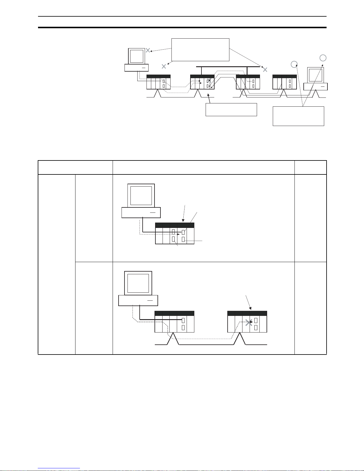
39
CJ1-H/CJ1M CPU Unit Ver. 2.0 Upgrades Section 1-6
Note This function prohibits writing by FINS commands only, so it has no effect on
write operations by functions other than FINS commands, such as data links.
Example Write Protection Patterns
PLC #1
PLC #2
PLC #3
Computer #1
Network
Write operations by FINS commands are prohibited from some
nodes in the network (in this example, computer #1, PLC #1, and
PLC #2).
Network
Write access to this PLC
is enabled/disabled.
Network
Computer #2
Write operations by FINS commands are not prohibited from
selected nodes in the network
(in this example, computer #2
and PLC #3).
Connection pattern Diagram (example) Write
protection
From a computer through
a direct serial
connection
Direct connection to
PLC
Cannot be
applied.
Gateway connection
(Serial-to-network) to PLC
Can be
applied.
PLC
Computer
Write-protection not effective
Peripheral port
RS-232C port
Serial connection
(Peripheral bus or
host link)
RS-232C port or 422A/485 port
on a Communications Board/Unit
PLC #1 PLC #2
Computer
Serial connection
(Peripheral bus
or host link)
Network
The CPU Unit in PLC #2
can be write-protected.
Page 88
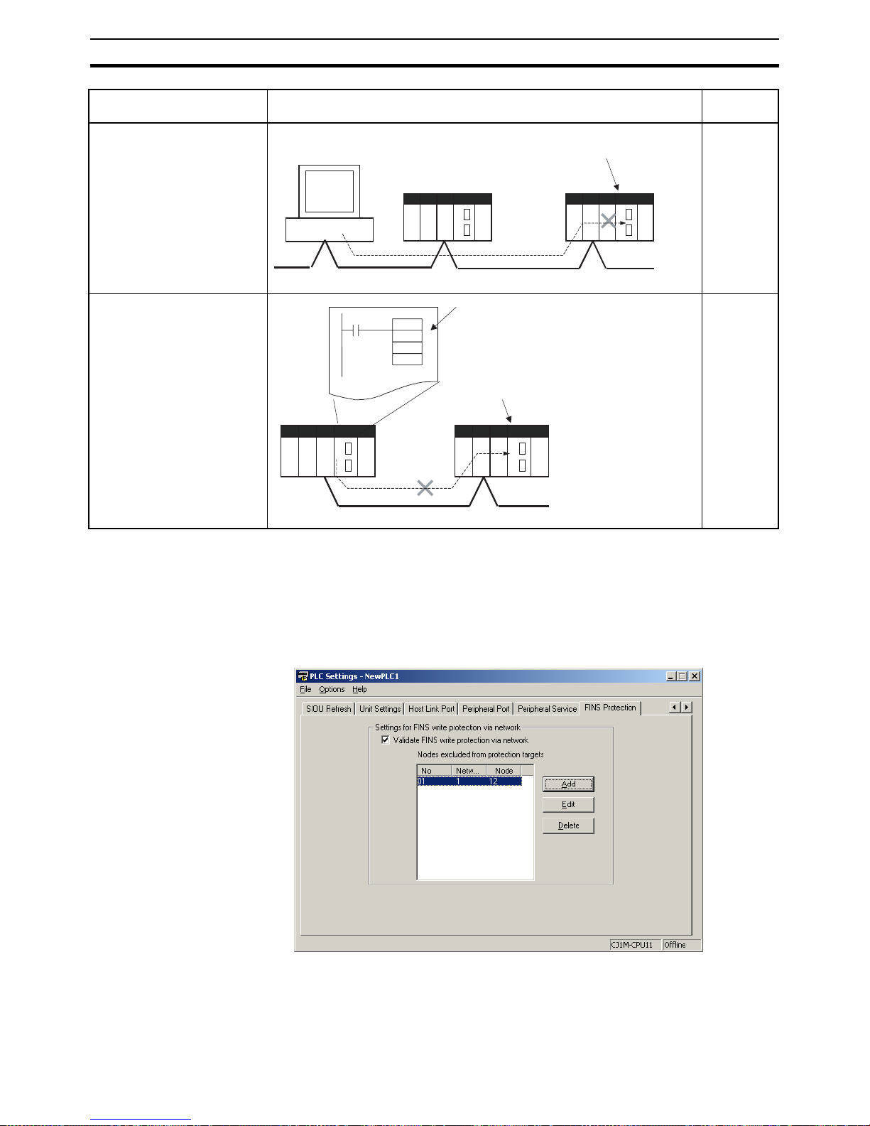
40
CJ1-H/CJ1M CPU Unit Ver. 2.0 Upgrades Section 1-6
Operation With the CX-Programmer, open the PLC Setup's FINS Protection Tab a nd
select the Use FINS Write Protection Option. When this option is selected, it
will not be possible to execute write operations for that CPU Unit with FINS
commands sent through a network. To permit write operations from particular
nodes, enter network addresses and node addresses for the node under Pro-
tection Releasing Addresses. (Up to 32 nodes can be excluded from FINS
Write Protection).
From a computer through a
direct network connection
Can be
applied.
From another PLC in the network
Can be
applied.
Connection pattern Diagram (example) Write
protection
PLC #1 PLC #2
Computer
Network
The CPU Unit in PLC #2
can be write-protected.
PLC #1 PLC #2
CMND
If the CMND instruction is used to send
a FINS command (requesting a write
operation) to the CPU Unit of PLC #2,
the operation is not performed.
The CPU Unit in PLC #2
can be write-protected.
Network
Page 89

41
CJ1-H/CJ1M CPU Unit Ver. 2.0 Upgrades Section 1-6
PLC Setup
Usage The system can be configured so that a PLC can be written only from autho-
rized nodes in the network. (For example, use this function when the system's
control/monitoring computer is the only node allowed to write to a Controller
within a piece of equipment.)
By limiting the number of nodes that can write to the PLC, it is possible to prevent system problems caused by unintentional overwrites during data monitoring.
Item Address in
Programming
Console
Description Settings Default setting
Use FINS Write Protection
Word 448, bit 15 Sets whether the CPU Unit is
write-protected from FINS commands sent through the network.
(Does not prohibit FINS commands sent through a direct serial
connection).
0: Write protection
disabled
1: Write protection
enabled
0: Write protection
disabled
Nodes Excluded
from Write Protection (Protection
Releasing
Addresses)
Words 449 to
480
This area lists the nodes in the
network that are not restricted by
FINS write protection. Up to 32
nodes can be specified.
Note These settings are effective
only when FINS write protection is enabled.
Bits 08 to 15Network address:
Network address of the FINS command source
00 to 7F hex
Bits 00 to 07Node address:
Node address of the FINS command source
01 to FE hex, or FF
hex
(FF hex: node
address unspecified)
Number of Nodes
Excluded from FINS
Write Protection
(Do not set this
value. It is automatically calculated by
the CX-Programmer.)
Word 448, bits
00 to 07
Contains the number of nodes that
are not subject to the FINS write
protection.
If 0 is specified (no nodes
excluded from write protection),
FINS write commands are prohibited from all nodes other than the
local node.
Note This setting is effective only
when FINS write protection
is enabled.
0 to 32
(00 to 20 hex)
(A value of 0 indicates that all nodes
are subject to write
protection.)
0
(All nodes subject to
write protection.)
Page 90

42
CJ1-H/CJ1M CPU Unit Ver. 2.0 Upgrades Section 1-6
Operations Restricted by
Network FINS Write
Protection
FINS Write Commands
The following FINS commands are restricted by FINS write protection when
sent to the CPU Unit through the network.
CS/CJ-series PLC
Equipment
Network
Controller
Allowed to
write/control PLC
Network
Network
System control/monitoring computer
Allowed to
write/control PLC
Monitoring computer
Not allowed to
write/control PLC
Code Command name Code Command name
0102 hex MEMORY AREA WRITE 2101 hex ERROR CLEAR
0103 hex MEMORY AREA FILL 2103 hex ERROR LOG POINTER CLEAR
0105 hex MEMORY AREA TRANSFER 2203 hex SINGLE FILE WRITE
0202 hex PARAMETER AREA WRITE 2204 hex FILE MEMORY FORMAT
0203 hex PARAMETER AREA FILL (CLEAR) 2205 hex FILE DELETE
0307 hex PROGRAM AREA WRITE 2207 hex FILE COPY
0308 hex PROGRAM AREA CLEAR 2208 hex FILE NAME CHANGE
0401 hex RUN 220A hex MEMORY AREA-FILE TRANSFER
0402 hex STOP 220B hex PARAMETER AREA-FILE TRANSFER
0702 hex CLOCK WRITE 220C hex PROGRAM AREA-FILE TRANSFER
0C01 hex ACCESS RIGHT ACQUIRE 2215 hex CREATE/DELETE DIRECTORY
2301 hex FORCED SET/RESET
2302 hex FORCED SET/RESET CANCEL
Page 91

43
CJ1-H/CJ1M CPU Unit Ver. 2.0 Upgrades Section 1-6
Operations from CX-Programmer (including CX-Net) through the Network
The following CX-Programmer (including CX-Net) operations are restricted by
FINS write protection when performed on the CPU Unit through the network.
Note 1. FINS write protection does not prevent CX-Programmer operations from a
computer connected through a direct serial connection.
2. FINS write protection does not prevent the following file memory write operations.
• Automatic transfer from the Memory Card at startup
• Simple backup function (including backup operations to selected
Units/Boards)
• Writing files with the FWRIT (WRITE DATA FILE) instruction
Operations from Other Support Software
FINS write protection also prevents the following operations performed
through the network by the CX-Protocol and CX-Process.
• Changing the CPU Unit's operating mode, writing memory areas,
transferring PLC Setup settings, transferring the I/O table, forced set/
reset, and clearing the CPU Unit's error log
Operations from Applications That Use FinsGateway
FINS write protection prevents all write operations addressed to the CPU Unit
from applications that use FinsGateway, such as PLC Reporter and Compolet.
1-6-4 Online Network Connections without I/O Tables
Summary With CJ-series CPU Units, the CPU Unit can recognize a CPU Bus Unit (such
as a Network Communications Unit, see note) even if the I/O tables have not
been created and there is no registered I/O tables as a result of using automatic I/O allocation at startup.
Operations not
allowed through the
network when FINS
write protection is
enabled.
• Changing the Operating Mode
• Transferring the ladder program to the CPU Unit
• Transferring parameter area data (PLC Setup, I/O table, and
CPU Bus Unit Setup) to the CPU Unit
• Transferring memory area data (I/O memory data) to the
CPU Unit
• Transferring the variable table, comments, or program index
to the CPU Unit
• Forced Set/Reset
• Changing timer/counter set values
• Online editing
• Writing file memory
• Clearing the error log
• Setting the clock
• Releasing the access right
• Transferring the routing table
• Transferring the data link table
Page 92

44
CJ1-H/CJ1M CPU Unit Ver. 2.0 Upgrades Section 1-6
Note Network Communications Units include Ethernet Units, Controller Link Units,
SYSMAC Link Units, and DeviceNet Units.
Usage If the nodes are connected to the network, this function allows a computer-
based Programming Device (such as the CX-Programmer) to connect online
to PLCs in the network even if the I/O tables have not been created. Since a
network connection is established with the PLCs, setup operations can be
performed such as creating the I/O tables (or editing and transferring I/O
tables), transferring the user program, transferring the PLC Setup, and transferring the CPU Bus Unit Setup.
This function is particularly useful when connecting the CX-Programmer via
Ethernet (using a CS1W-ETN21), because the I/O tables can be created
through Ethernet so a serial cable isn't required and it isn't necessary to
spend extra time establishing a serial connection.
Details
• Applicable Units: All CS/CJ-series CPU Bus Units
• Applicable computer-based Programming Devices: CX-Programmer and
CX-Protocol only
• Applicable functions: Online connections from CX-Programmer and CXProtocol, and online functions of the applicable CPU Units and CPU Bus
Units
Note When a CS1W-ETN21 or CJ1W-ETN21 Ethernet Unit is being used, the
Ethernet Unit's IP address is automatically set to the default value of
192.168.250.xx, where xx is the FINS node address. After connecting the ethernet cable between the CX-Programmer and PLC (without making a direct
CPU Bus Unit
(including Network Communications Units)
CS/CJ-series CPU Unit Ver.2.0 or higher
Network
Online connection
can be made.
CPU Bus Units (including Network Communications Units)
can be recognized before I/O tables are created (I/O allocation at startup is used).
CX-Programmer
Ethernet
Ethernet
CX-Programmer
1:1 Computer-to-PLC connection 1:N Computer-to-PLC connection
Even without an I/O table, it is
possible to make an online connection, create the I/O table,
transfer the program, and perform other operations.
CS/CJseries
CPU Unit
Ver.2.0
CS/CJseries
CPU Unit
Ver.2.0
CS/CJseries
CPU Unit
Ver.2.0
I/O table not registered I/O table not registered I/O table not registered
Even without an I/O table, it is possible to make an online
connection, create the I/O table, transfer the program, and
perform other operations.
CS/CJseries
CPU Unit
Ver.2.0
I/O table not
registered
Page 93

45
CJ1-H/CJ1M CPU Unit Ver. 2.0 Upgrades Section 1-6
serial connection and creating the I/O tables), manually set the computer's IP
address in the Windows Local Area Connection Properties (example:
192.168.250.55). An online connection can be established just by setting the
Ethernet Unit's IP address (192.168.250.xx) and node in the CX-Programmer.
1-6-5 Communications through a Maximum of 8 Network Levels
Previous CPU Units (Pre-Ver. 2.0 CPU Units)
With the pre-Ver. 2.0 CPU Units, it was possible to communicate through 3
network levels max. (see note), including the local network. It was not possible
to communicate through 4 or more levels.
Note A Gateway to the network via serial communications was not counted as a
level.
CPU Unit Ver. 2.0 or Later
Summary With the CPU Unit Ver. 2.0 and later CS/CJ-series CPU Units, it is possible to
communicate through 8 network levels max. (see note), including the local
network.
Note 1. FINS commands can only be sent across up to 8 network levels when the
destination is a CPU Unit. FINS commands can be sent to other destinations up to 3 network levels away.
2. This functionality is enabled only after setting routing tables with the CXNet in CX-Programmer version 4.0 or higher.
3. A Gateway to the network via serial communications was not counted as a
level.
Compatible Networks
Only the following 2 kinds of networks can be used when communicating
through a maximum of 8 networks. The network levels can be combined in
any order.
• Controller Link
• Ethernet
Note Communications are restricted to a maximum of 3 networks through
DeviceNet and SYSMAC Link networks.
Configuration of Compatible Models
All of the CPU Units must be CPU Unit Ver. 2.0 and later CS/CJ-series CPU
Units. Also, the Gateway Counter Setting must be made with the CX-Net.
OR
FINS command
source
Serial
connection
Network 1
This connection is not counted as a network level.
Level count = 1
Network 2
Level count = 2
Network 3
FINS command
destination
Page 94

46
CJ1-H/CJ1M CPU Unit Ver. 2.0 Upgrades Section 1-6
Internal Structure The Gateway Counter (GCT) is in the FINS header of the FINS command/
response frame. This counter value is decremented (−1) each time a network
level is crossed.
FINS Command Frame
Example:
Operating Procedure There is no special procedure that must be performed for CS/CJ-series CPU
Units Ver. 2.0 or later. Just set normal routing tables to enable communicating
across up to 8 network levels.
Note 1. When using communications only for up to 3 network levels, the CS/CJ-se-
ries CPU Units Ver. 2.0 or later can be used together with other CPU Units.
When using communications for to 4 to 8 network levels, use only CS/CJseries CPU Units Ver. 2.0 or later. Other CPU Units cannot be used. Routing errors (error codes 0501 to 0504 hex) may occur in the relaying PLCs,
preventing a FINS response from being returned.
2. With CS/CJ-series CPU Units with unit version 2.0 or later, the Gateway
Counter (GCT: Number of allowed bridge passes) for FINS command/response frames is the value decremented from 07 hex (variable). (In earlier
versions, the value was decremented from 02 hex.) With unit version 3.0
or later, the default GCT for FINS command/response frames is the value
decremented from 02 hex. CX-Net can be used to select 07 hex as the value from which to decrement.
3. Do not use the Gateway Counter (GCT: Number of allowed bridge passes)
enclosed in the FINS header of the FINS command/response frame in ver-
OR
FINS command
source
Serial
connection
This connection is not counted as a network level.
Network 1
Network 2
Level
count = 1
Level
count = 4
Level
count = 3
Level
count = 2
Network 4
Network 3
Network 8
Network 7
Level
count = 7
FINS command
destination
ICF RSV GCT
FINS header Command code Text
GCT (Gateway counter: Number of allowed bridge passages)
The standard setting is 02 hex when sending, but this value can be
user-set from 07 hex.
The count is decremented by one each time a network level is passed.
FINS command
source
FINS command
Network 1
Network 2
Network 3
FINS command
At this point, the gateway counter = 7 hex
At this point, the gateway counter = 6 hex
FINS command
FINS command
Network 4
At this
p
oint, the gateway counter = 5 hex
At this point, the gateway counter = 4 hex
FINS command
At this point, the gateway counter = 0 he
x
Network 8
FINS command
destination
Page 95

47
CJ1-H/CJ1M CPU Unit Ver. 2.0 Upgrades Section 1-6
ification checks performed by user applications in host computers. The
GCT in the FINS header is used by the system, and a verification error may
occur if it is used to perform verification checks in user applications, particularly when using CS/CJ-series CPU Units with unit version 2.0 or later.
1-6-6 Connecting Online to PLCs via NS-series PTs
Summary The CX-Programmer can be connected online to a PLC connected via a serial
line to an NS-series PT that is connected to the CX-Programmer via Ethernet
(see note 2). This enables uploading, downloading, and monitoring the ladder
program and other data.
Note 1. The NS-series PT must be version 3.0 or higher and the CX-Programmer
must be version 3.1 or higher.
2. Connection is not possible through an NS-series PT connected serially to
the CX-Programmer.
Connection Method In CX-Programmer, open the Change PLC Window and set the Network Type
to Ethernet. Click the Settings Button and set the IP address of the NS-series
PT on the Driver Tab Page. Also make the following settings on the Network
Tab Page.
• FINS Source Address
Set the local network address of the NS-series PT for the Network (example network address: 1).
• FINS Destination Address
Network: Set the address to 111 if the PLC is connected to serial port A
on the NS-series PT and to 112 if it is connected to serial port B.
Node: Always set to 1
• Frame Length: 1,000 (See note.)
• Response Timeout: 2
Note Do not set the frame length higher than 1,000. If any higher value is used, the
program transfer will fail and a memory error will occur.
PLC #1
CX-Programmer
(Example IP address: 192.168.0.1)
Ethernet (See note 1.)
(Example network address: 1)
CS/CJ-series
CPU Unit Ver. 2.0
Connect online to PLC #1 to enable
programming, monitoring, and other operations.
NS-series PT
(Example IP address:
192.168.0.22)
1:N NT Link
(Example network address: 111)
Page 96

48
CJ1-H/CJ1M CPU Unit Ver. 2.0 Upgrades Section 1-6
1-6-7 Setting First Slot Words
Previous CPU Units (Pre-Ver. 2.0 CPU Units)
With CX-Programmer Ver. 3.0 or lower, only the first addresses on Racks
could be set. The first address for a slot could not be set.
CX-Programmer Ver. 3.1 or Higher
Summary Starting with CX-Programmer Ver. 3.1, the first addresses for slots can be set
when editing the I/O tables for CS/CJ-series CPU Units (CS1D CPU Units for
Single-CPU Systems, and CS1-H, CJ1-H, and CJ1M CPU Units). The first
address can be set for up to eight slots. (See note.)
Note This function is supported only for CS1-H/CJ1-H CPU Units manufactured on
June 1, 2002 or later (lot number 020601@@@@ or later). It is supported for all
CJ1M CPU Units regardless of lot number. It is not supported for CS1D CPU
Units for Duplex CPU Systems.
Operating Procedure Select Option - Rack/Slot Start Addresses in the PLC IO Table - Traffic Con-
troller Window. This command will enable setting both the first Rack
addresses and the first slot addresses.
0 1 2
01 23 4
01 2
CIO 0100
CIO 0000
CIO 0200
CX-Programmer
Ver. 3.0 or earlier
First addresses on Racks
Rack No.
CPU Rack
Rack 1
Rack 2
Rack 3
Rack 4
Rack 5
Rack 6
Rack 7
First address
100
0
200
Example:
CPU Rack slot
Rack 1 slot
Rack 2 slot
Page 97

49
CJ1-H/CJ1M CPU Unit Ver. 2.0 Upgrades Section 1-6
This function can be used, for example to allocate fixed addresses to Input
Units and Output Units. (With CQM1H PLCs, input bits are from IR 000 to
IR 015 and output bits are from IR 100 to IR 115. First slot addresses can be
set when replacing CQM1H PLCs with CS/CJ-series PLCs to reduce conversion work.)
Note The first address settings for Racks and slots can be uploaded/downloaded
from/to the CPU Unit.
Double-click
Select Option - Rack/Slot Start Addresses.
100
0
102
1
105
5
0
12
01
2
01 2
34
Slot No.
Slot No. 00
Slot No. 02
Slot No. 00
Slot No. 02
Slot No. 00
Slot No. 01
CIO 0005
CIO 0105
CIO 0001
CIO 0102
CIO 0000
CIO 0100
CX-Programmer
Ver. 3.2 or higher
Rack No.
CPU Rack
CPU Rack
Rack 1
Rack 1
Rack 2
Rack 2
Example:
CPU Rack slot
Rack 1 slot
Rack 2 slot
Up to 8 settings
can be made.
First slot addresses
Page 98

50
CJ1-H/CJ1M CPU Unit Ver. 2.0 Upgrades Section 1-6
CPU Unit Ver. 2.0 or Later and CX-Programmer Ver. 4.0 or Higher
Summary When using CX-Programmer Ver.4.0 or higher with CPU Unit Ver. 2.0 or later,
the first address can be set for up to 64 slots.
Note This function is supported only for CS1-H, CJ1-H, and CJ1M CPU Units
Ver. 2.0 or later. It is not supported for CS1D CPU Units for Duplex-CPU Systems.
1-6-8 Automatic Transfers at Power ON without a Parameter File
Previous CPU Units (Pre-Ver. 2.0 CPU Units)
Previously with the CS/CJ-series CPU Units, both the program file for automatic transfer at power ON (AUTOEXEC.OBJ) and the parameter file for automatic transfer at power ON (AUTOEXEC.STD) had to be stored on the
Memory Card to enable automatic transfers to the CPU Unit at power ON.
Also, the parameter file for automatic transfer at power ON (AUTOEXEC.STD)
could not be created without the actual PLC (regardless of whether it was
made in online operations from the CX-Programmer or a Programming Console or by using the easy backup operation).
Even if a program file (.OBJ) was created offline without the actual PLC and
then sent to a remote PLC as an email attachment, the program file could not
be transferred to the CPU Unit without a Programming Device.
100
0
102
1
105
5
50
0
12
01
2
01 2
34
01 2
Slot No.
Slot No. 00
Slot No. 02
Slot No. 00
Slot No. 02
Slot No. 00
Slot No. 01
Slot No. 01
Example:
CIO 0005
CIO 0105
CIO 0001
CIO 0102
CIO 0000
CIO 0100
CIO 0050
CIO 0155
CX-Programmer
Ver. 4.0 or higher
Rack No.
CPU Rack
CPU Rack
Rack 1
Rack 1
Rack 2
Rack 2
Rack 7
CPU Rack slot
Rack 1 slot
Rack 2 slot
Up to 64 settings
can be made.
Rack 7 slot
CPU Unit Ver. 2.0
or higher
First slot addresses
Page 99

51
CJ1-H/CJ1M CPU Unit Ver. 2.0 Upgrades Section 1-6
CPU Unit Ver. 2.0 or Later
Summary With CS/CJ-series CPU Unit Ver. 2.0, the user program can be automatically
transferred to the CPU Unit at power ON without a parameter file (.STD) if the
name of the program file (.OBJ) is changed to REPLACE.OBJ on the CX-Programmer and the file is stored on a Memory Card. If data files are included
with the program file using this function, the following data file names are
used: REPLACE.IOM, REPLCDM.IOM, REPLCE@.IOM.
Note 1. If the Memory Card contains a REPLACE.OBJ file, any parameter file on
the Memory Card will not be transferred.
2. If the Memory Card contains both a REPLACE.OBJ file and a AUTOEXEC.OBJ file, neither will be transferred.
Note With CX-Programmer Ver. 3.0 or higher, a program file (.OBJ) can be created
offline and saved on a computer storage media. Select Transfer - To File
from the PLC Menu. This enable creating a program file offline without a PLC
so that the name can be changed to enable sending the program file.
1-6-9 Operation Start/End Times
Previous CPU Units (Pre-Ver. 2.0 CPU Units)
The time that operation started and the time operation ended were not stored
in the CPU Unit.
CPU Unit Ver. 2.0 or Later
The times that operation started and ended are automatically stored in the
Auxiliary Area.
Personal
computer
Mail
Mail
Internet
Program file (.OBJ) sent
as mail attachment.
CPU Unit
Local site (no Programming Device)
Program cannot be transferred
(see note).
Program file
(AUTOEXEC.OBJ)
Note: Transfer is not possible because
there is no parameter file
(AUTOEXEC.STD).
Personal
computer
Mail
Mail
Internet
Program file created on CXProgrammer (see note), file name
changed to REPLACE.OJB, and
file sent as mail attachment.
CPU Unit
Remote site (no Programming Device)
Program can be transferred
(see note).
REPLACE.OBJ
Note: Transfer is possible even
without a parameter file
(AUTOEXEC.STD).
Page 100

52
CJ1-H/CJ1M CPU Unit Ver. 2.0 Upgrades Section 1-6
• The time that operation started as a result of changing the operating
mode to RUN or MONITOR mode is stored in A515 to A517 of the Auxiliary Area. The year, month, day, hour, minutes, and seconds are stored.
• The time that operation stopped as a result of changing the operating
mode to PROGRAM mode or due to a fatal error is stored in A518 to
A520 of the Auxiliary Area. The year, month, day, hour, minutes, and seconds are stored.
This information simplifies managing PLC System operating times.
1-6-10 Automatic Detection of I/O Allocation Method for Automatic
Transfer at Power ON
Previous CPU Units (Pre-Ver. 2.0 CPU Units)
Previously with the CJ-series CPU Units, when a parameter file for automatic
transfer at power ON (AUTOEXEC.STD) was recorded in a Memory Card, the
user-set I/O allocation method was automatically used when an automatic
transfer at power ON was executed from the Memory Card, and I/O was allocated according to the parameter file for automatic transfer at power ON. As a
result, the following case occurred:
1,2,3... 1. In an office where Units were not mounted, the CX-Programmer was con-
nected online to just the CPU Unit, and files for automatic transfer at power
ON were created (without creating/transferring I/O tables).
2. These files for automatic transfer at power ON were then saved in the
Memory Card, which was then taken to the remote site where automatic
transfer at power ON was executed.
3. When automatic transfer at power ON was executed, I/O tables were created based on the parameter file for automatic transfer at power ON saved
in the Memory Card (i.e., the file created when Units were not mounted to
the PLC). As a result, the registered I/O tables did not match the Units actually mounted in the CPU Unit, causing an I/O setting error.
CX-Programmer
Memory Card
Remote site
Office
I/O not allocated according to settings in mounted Units
User-set I/O allocation
Units are mounted
CJ-series CPU Unit
Program file for automatic
transfer at power ON
(AUTOEXEC.OBJ)
Parameter file for automatic
transfer at power ON
(AUTOEXEC.STD)
Mail
Automatic I/O allocation at startup
Units not mounted.
Create program files for automatic
transfer at power ON
(AUTOEXEC.OBJ) and parameter
files for automatic transfer at
power ON (AUTOEXEC.STD).
Program file for automatic
transfer at power ON
(AUTOEXEC.OBJ)
Parameter file for automatic
transfer at power ON
(AUTOEXEC.STD)
Note: The parameter file for automatic transfer
at power ON (AUTOEXEC.STD) is
present, and this file is used to allocated
I/O instead of the I/O allocations in the
mounted Units.
Mis-match
(See note.)
 Loading...