

Series
Programmable Controllers
CJ1G-CPU P Loop-control CPU Unit
Unit Version 3.5 (Version Upgrade)
CJ1 Special I/O Units
Process Analog Input Units
(Isolated Units with Fully Universal Inputs)
CJ1W-PH41U (High-resolution Unit) and CJ1W-AD04U (General-purpose Unit)
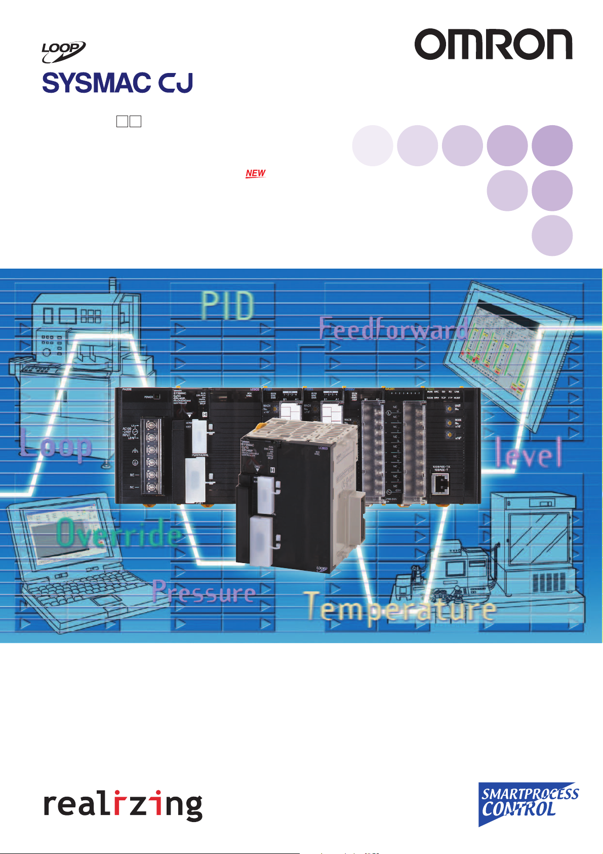
Fully Integrated Sequence and Loop Control
New Built-in Loop Controller
Introducing the New Style of Loop Control
Advanced controller functions integrated with the same CJ-series
functionality and high-speed capabilities
Function block programming for
easy engineering
Seamless integration of sequence
control and loop control.
HMI windows can be simply
generated from function blocks
automatically.
Ultra-small size fits in most
devices
Backplane-free structure provides
the functions you need in
minimum space.
Low-cost solution for controlling
multiple loops
Control functions have the added
ability to control multiple loops.
Consolidating the proven CSseries loop-control technology
Effective maintenance functions
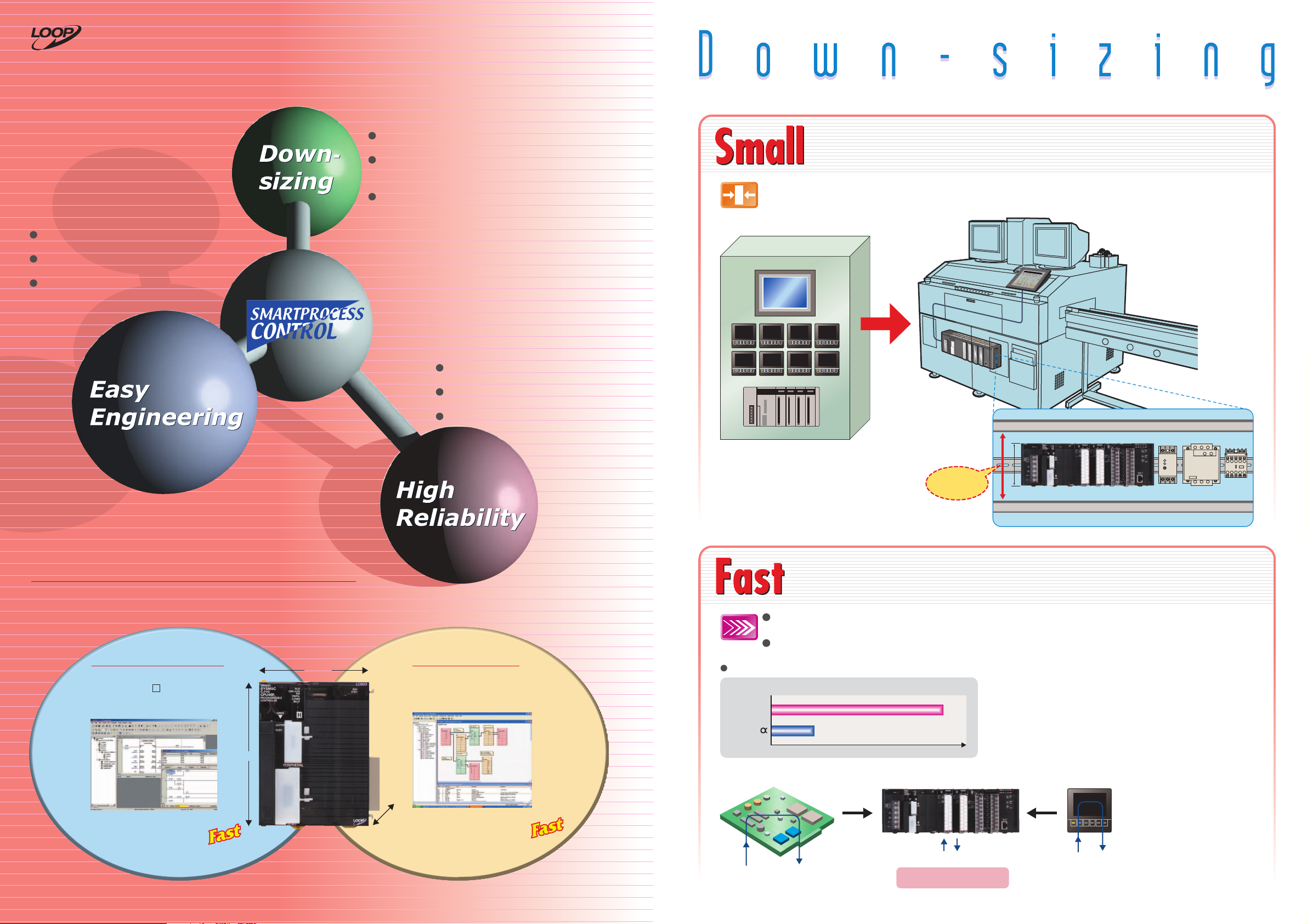
Super compact: Only 90 mm High and 65 mm Deep, and
Backplane-free structure enables flexible width design.
Compact PLC Aids Machine Downsizing by Fitting Just About Anywhere.
Wide Array of I/O Units, Special I/O Units, and CPU Bus Units Are Available to Suit Your Application.
Duct
90 mm high
Power supply SSR Contactor
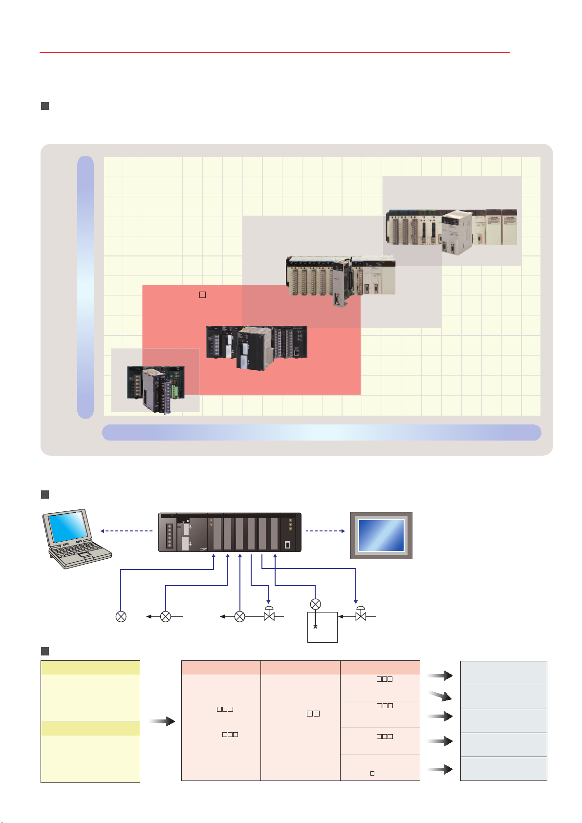
Integrated Loop Control and Sequence Control
An engine for controlling analog quantities (e.g., temperature, pressure, flowrate) is built into the CPU Unit together
with the engine for executing sequence control, delivering high-speed sequence control and high-speed, advanced
analog quantity control in a single Unit.
Sequence Control Engine Loop Control Engine
CPU Unit element:
CJ1G-CPU4 H
CX-Programmer sequence control program
(ladder, function block, structured text)
90 mm
69 mm
Loop Controller Element:
Up to 300 or 50 function blocks
CX-Process loop control program (function blocks)
Sequencing
PCMIX Values
CJ1G
SYSMAC
Greatly
reduces space
between ducts
Duct
S82K G3J J7AN
High-speed sequence control functions can be used directly for
high-speed, advanced loop control.
Sequence control: Executes 20-Kstep ladder programs in 1 ms (with basic instructions only).
PCMIX = 7.4 LD or OUT executed in 40 ns
Loop control: Executes PID operations for 20 loops in up to 10 ms. This is a guide for general
1.4
(See note.)
Note: Loop configuration: Ai4 Terminal + Segment Linearizer + Basic PID + Ao4 Terminal
The external I/O response time in the overall system refers to the conversion time.
7.4
SYSMAC CJ-series PLCDedicated microcomputer board
Digital Controller
applications.
Execute 20-Kstep ladder
programs in 1 ms
Note: Basic instructions only
20-Kstep
1 ms
(See note.)
D: 65 mm
Loop-control
CPU Unit
2
Execute PID Control for
20 Loops 10 ms
20 Loops in 10 ms
Note: General application (e.g., loop
configuration: Ai4 Terminal + Segment
Linearizer + Basic PID + Ao4 Terminal)
(See note.)
High-speed processing
(Example: 1-ms response)
The same level of high-speed processing
Only One CPU Unit Needed
High-speed processing
(Example: 50 ms)
3
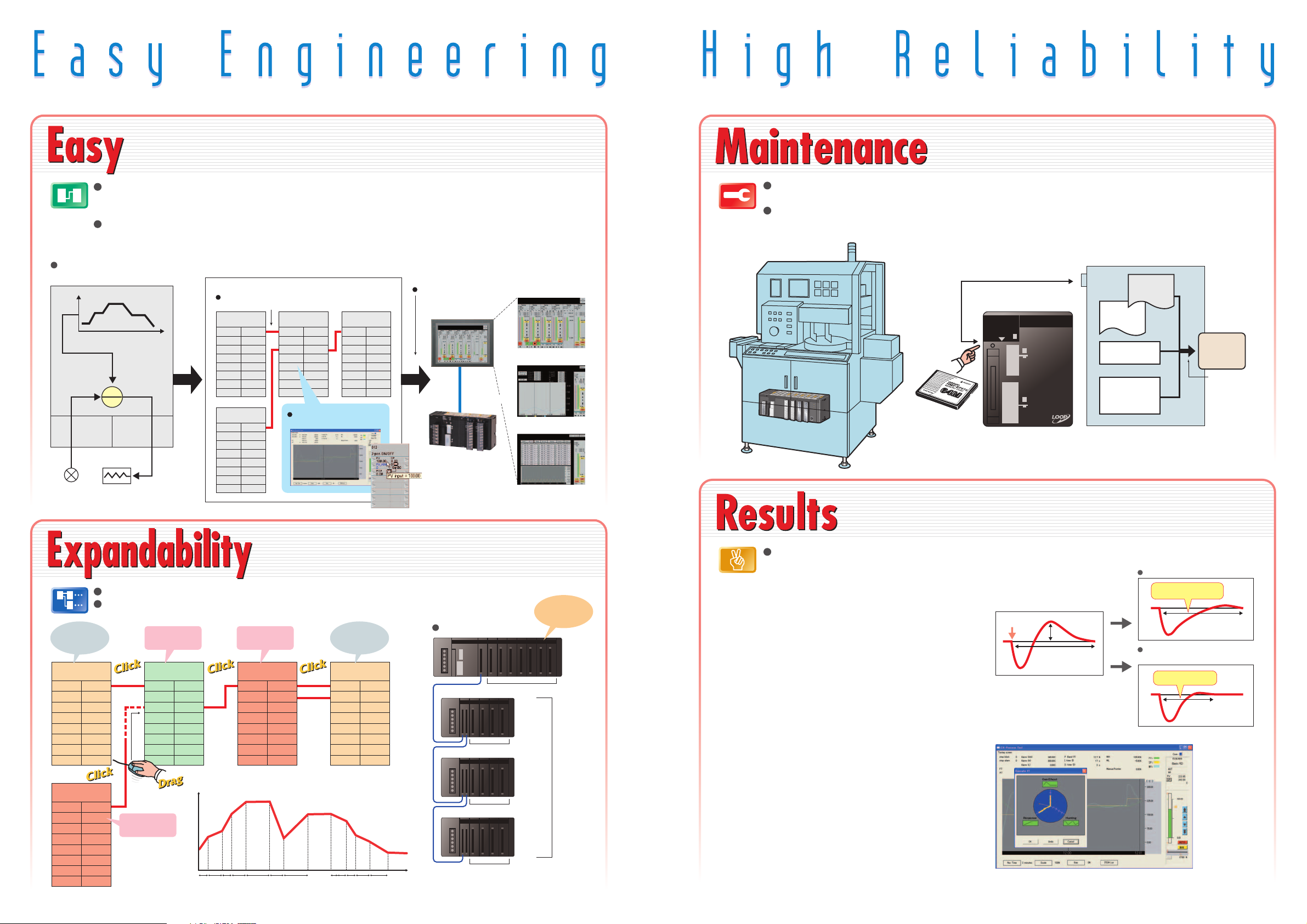
Function blocks make loop-control programming easy. You can also create
CX-Process Tool tuning windows to help adjust loops. Controller faceplates
can be created automatically for touch panel displays.
Simply turn the DIP Switch ON/OFF to save or read the
user program including function blocks using the
Memory Card.
Engineering Example: Program Control
Loop-control CPU Unit
SP
Analog
Input
Unit
Input
channel 1
Temperature
input
Read data from
Analog Input
Units
Analog Input
Field Terminal
Segment
Program 2
X1
4
Sequence control programs: Standardize and simplify programs using structured programming. Special I/O
Unit and CPU Bus Unit settings are easy with function blocks (using ladder programming language or
structured text).
Loop control programs: By combining function blocks, a wide array of control methods can be easily
configured, from basic PID control used by Temperature Controllers to program, cascade, and feed-forward
control. Easily display values, such as temperatures, in engineering units, allowing you to check operation.
Face Plate Auto-Builder for NS
3
Touch panel windows are automatically generated.
NT-series PT
Control window
Serial or
Ethernet
communications
Tuning window
Loop-control CPU Unit
Segment program
parameter setting window
RSP
PV
MV
TIC
Analog
Output
Unit
Output
channel 1
Heater output
Time
CX-Process Tool (Software for Personal Computer)
1
Combine function blocks and connect graphically
using the mouse.
Analog Input
Field Terminal
Y1
Y2
Y3
Y4
Segment
Program
Y1
Basic PID
PV
RSP
MV
2
Adjust PID and other parameters
in the tuning window.
Analog Output
Field Terminal
X1
X2
X3
X4
Lineup includes low-cost models that use up to 50 function
blocks and models that allow up to 300 blocks designed for
large-scale systems and complicated operations.
Loop control: Programming with function blocks to suit the application.
System configuration: Choose and combine functions from a broad selection of I/O Units.
System Configuration
Expansion Rack
Expansion Rack
Expansion Rack
Note: CJ1G-CPU44P/45P
(CJ1G-CPU42P/43P: Expand up to 2 Racks)
10 Units max.
10 Units max.
10 Units max.
10 Units max.
Y1
Y2
Y3
Y4
Y5
Y6
Y7
Y8
Y1
Y2
Perform PID
control
Basic PID
PV
RSP
Perform program
control
Perform
heating/cooling
control
Split Conversion
SP
DV
MV
Set point (SP)
T0 T1 T2 T3 T4 T5 T6 T97 T98 T99 T100 TIME
Y1X1
Y2
Control output
from Analog
Output Unit
Analog Output
Field Terminal
X1
X2
X3
X4
X5
X6
X7
X8
Process Input
Units, Analog
I/O Units, etc.
Expansion
Rack: 3
Racks
max.
(See note.)
Simple backup function enables backup, recovery, and comparison of all PLC data including the
function block programs for the Loop Control Board using the Memory Card.
Save tag settings, comments, annotations, and connection data created using the CX-Process
Tool to either a Memory Card or a Loop-control CPU Unit.
Press the
Memory Card
power supply
switch for 3 s.
Consolidating OMRON's expertise in temperature and process control
cultivated over many years to provide you with effortless solutions
using proven algorithms.
Loop control: Proven functionality of Temperature Controllers and CS-series Loop Control
Boards (see note 1) in a compact size.
New Algorithm Further Enhances Control
Stability
Disturbance Overshoot Adjustment
This function restrains overshoot when a disturbance is
generated, allowing faster stabilization.
[Example]
• Temperature drops when adding objects to a furnace
• Control disturbances when retooling
Optimum Tuning to Suit the Application
Fine Tuning
Adjust PVs, SPs, and MVs while monitoring, and save
data as CSV files from the software tuning window.
Autotuning (AT) and fine-tuning functions can also be
used for automatically calculating PID constants (see note
2).
Note 1: For details on CS-series Loop Control Boards, refer to the PLC-based
Process Control Catalog (Cat. No. P051).
2: Control can be fine-tuned by automatically tuning PID parameters using
previous control parameters and three user-set requirements to execute
fuzzy logic.
Note: Supported by unit version 3.0 or later.
CPU Unit
Parameter Area
Condition: Pin 7 is ON
Disturbance generated
Disturbance
Overshoot
Time required to
stabilize
CS-Process Tool Tuning Window
Sequence
program
I/O memory
Function
block
program
Memory
Card
Simple backup
to Memory
Card, including
function block
data.
Conventional PID gain adjustment
Longer time required
to stabilize
Using the Disturbance
Overshoot Adjustment function
Faster stabilization
5
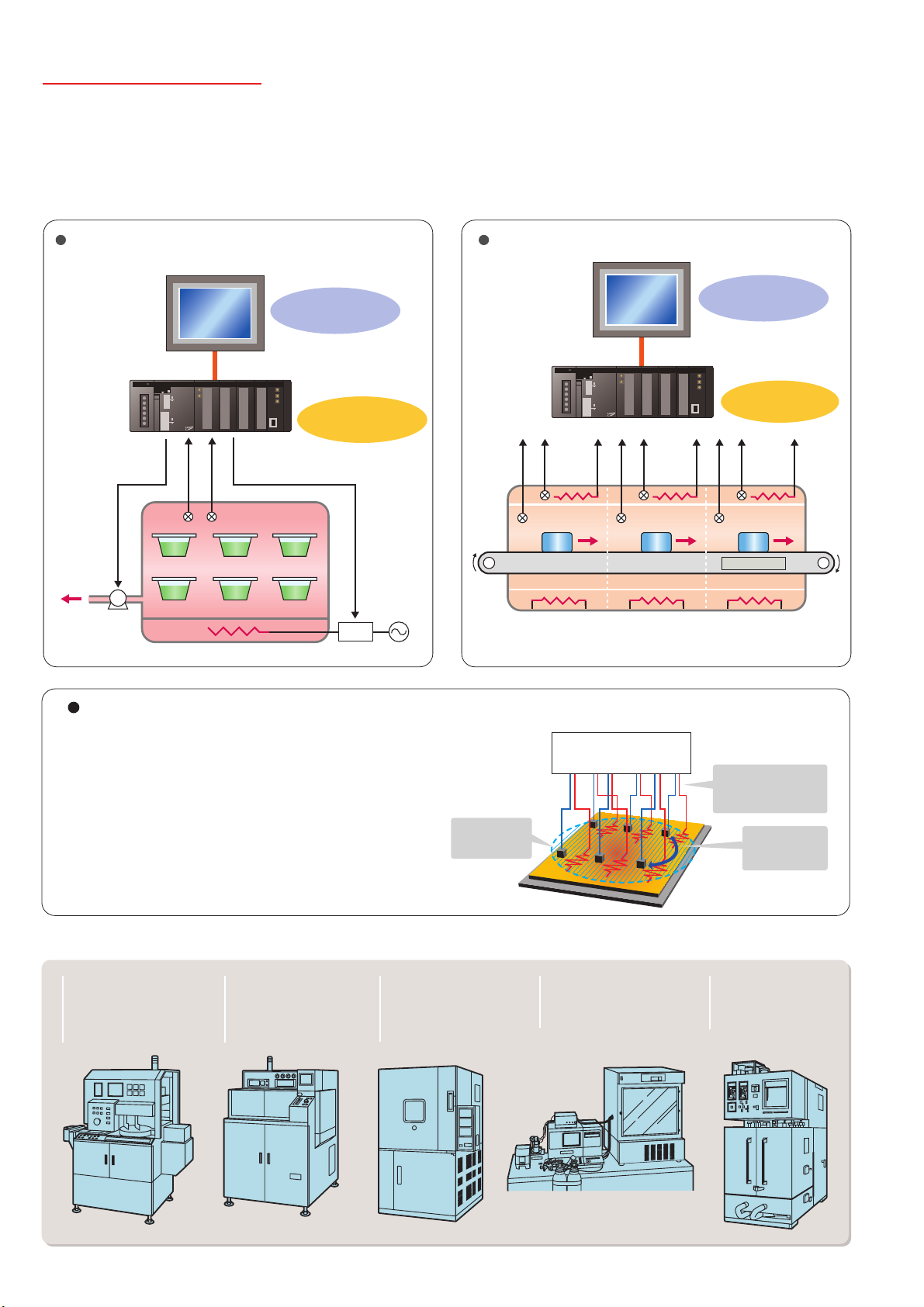
Applications
The Loop-control CPU Unit Provides You with Solutions for the Complex and Advanced
Functions Demanded by Control Devices in an Increasingly Diverse Range of Equipment.
Sterilization and Disinfection of
Pharmaceuticals, Food and Beverages
NS-series PT
Logging Trend Data
(monitoring and operation
windows)
Loop-control CPU Unit
Program pattern
Control outputsControl outputs
Pressure
Temperature
Thyristor
control
SCR
Industrial Furnace
NS-series PT
Workpiece
Conveyor
Heater
Temperature
sensor
Monitoring and operation
windows or heaters and
temperature sensors
Loop-control CPU Unit
Cascade control of
tunnel furnace
N2 atmosphere
Solder
Gradient Temperature Control for Planar
Temperature Control Across Multiple Points
Note: CJ1G-CPU45P-GTC only.
Gradient temperature control equalizes the temperatures at
multiple points, providing high-quality heat processing,
reducing energy loss until temperatures stabilize, and saving
labor in adjustments due to interference between heaters.
For details, refer to the SYSMAC CS/CJ Series Controllers for Gradient
Temperature Control Catalog (R141).
Providing Solutions to Other Problems
Electrical parts equipment
requiring high-speed
temperature control for
higher precision and
improved tact time.
Diffusion furnaces that
perform cascade control
of heater temperatures
and internal chamber
temperatures.
Example: Planar Temperature Control of Multi-stage Furnaces,
Wafer and Glass Surface Temperatures, and Other Applications.
Average
temperature
controlled.
Food machines, semiconductor devices and
other machines requiring
multipoint temperature
control.
Gradient temperature
control
Fermentation equipment
requiring temperature,
pressure, flowrate, and pH
control.
CPU: CJ1G-CPU45P-GTC
Interference at other
control output points
suppressed.
Temperature
differences
controlled.
Testing devices that
frequently change
setting conditions and
program settings.
6
Loop Control Machines and Product Variations
Model Selection
Compact CJ-series Loop-control CPU units are ideal for equipment with built-in applications. CS-series and CS1D
models designed for duplex systems are also available for processing equipment that requires high reliability.
Processing facilities
• Chemical/
pharmaceutical
• Utilities
• DCS replacement
• Water treatment
Etc.
Machinery
• Semi-conductor/
electrical components
• Industrial furnaces
(firing)
• Food machines
(sterilization)
• Testing equipment
Etc.
CJ1G-CPU4 P CJ-series
Loop-control CPU Unit
CJ-series
Temperature Control Unit
See note 1.)
(
CS-series/CS1D-S
Loop Control Board
(See note 2.)
CS1D-series
Process-control CPU Unit
(See note 2.)
• Packaging
machines
• General food
machines
High-speed and highly reliable (duplex)Easy Controlling analog quantities
Note 1: The Temperature Control Unit integrates control and I/O for either 2 loops or 4 loops.
Temperature control is achieved simply by setting parameters. (CX-Process cannot be used.)
2: For details on CS-series Loop Control Boards and Process-control CPU Units, refer to the PLC-based Process Control Catalog (Cat. No. P051).
System Configuration Example
Personal computer for
programming/
monitoring
PLC
4 to 20 mA
20 mA
Sensor Flow Rate Sensor Capacitive
4 to
20 mA
Flow Rate Sensor
Compensating
Conductor
4 to 20 mA4 to
Thermocouple
Process
4 to 20 mA
PT
Example of Peripheral Devices
Temperature Sensors
E52
Thermocouples
Platinum-resistance
Thermometers
Analog quantities (e.g., temperature,
flowrate, concentration)
ES1/ES1B
Infrared Thermosensors
Flow Rate Sensors,
Displacement Sensors,
Signal Converters, etc.
CJ1W-P
Analog Process
Input Unit
CJ1W-AD
Analog Input Unit
CJ1G-CPU P
Loop-control
CPU Unit
SYSMAC CJ Series
OutputControlInput
CJ1W-DA
Analog Output Unit
(linear output)
CJ1W-OD
Transistor Output Unit
(pulse output)
CJ1W-OC
Relay Output Unit
RS-485 communications:
Built-in serial port on CPU Unit
CJ1W-SCU 1-V1
• Position Control
G3PX Power Controller
• Cycle Control
G32A-EA + G3PA
• SSR
G3PA/B/C, G3NA, etc.
• ON/OFF Control
• Optimum Cycle Control
G3ZA
7
Peripheral Devices
Input Devices
Input Devices
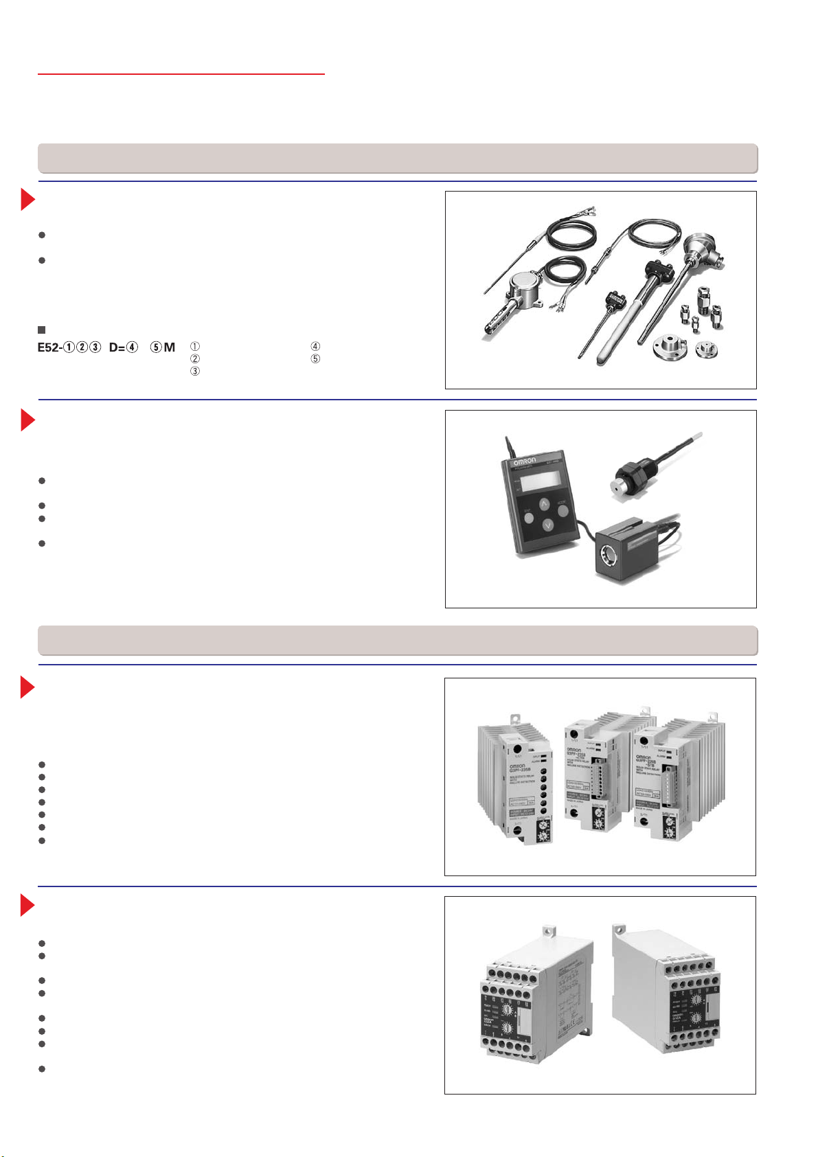
E52-series Temperature Controllers
Plenty of Variation to Suit an Extensive Range of Applications
Select from a variety of choices in number of elements, shape, protective
tubing length, and terminal type.
Economical models and special models are available as well as general purpose models. Select from a diverse range of models to suit the application:
Models for high temperatures, metal patterns, surface measurement, and
room temperatures, waterproof and anti-corrosive models, models for moving
parts, and models with double elements.
Model Structure
Element type
Protective tubing length
Example: E52-CA15A D:3.2 2M
Terminal type
ES1/ES1B-series Infrared Thermosensors
Hygienic temperature measurement without damaging the workpiece. Ideal for
workpieces on conveyors or other applications in which contact measurement is
difficult.
ES1 Series: Designed for high-precision, small-spot, high-temperature
measurements.
Two types of small spot: 3-mm dia. and 8-mm dia.
High-precision and high-speed measurement with a repeatability of ±0.5°C
and response speed of 0.4 s (95%).
Models are available for medium (–500 to 500°C), mid-low (–50 to 500°C),
and high (0 to 1000°C) temperature ranges.
Protective tubing model
Lead wire length
Output Devices
Output Devices
G3PF Solid-state Relay with Built-in
Current Transformer (CT)
Built-in current transformer is provided and heater burnouts and SSR shortcircuits can be detected.
Built-in current transformer reduces wiring work.
Detects the burnout of any one of multiple heaters.
Detects burnouts in 3-phase heaters.
Detects SSR short-circuits.
Error detection level can be easily set with a switch.
Can be mounted to a DIN Track or with screws.
Three types of input terminals are available: M3 terminals, screwless clamp
terminals (detachable), or compact slotted terminals (detachable).
G3ZA Multi-channel Power Controller
Optimum Cycle Control for High-precision Control with Low Noise
Smaller than power conditioners.
Power control with little noise is enabled by combining the Power Controller
with zero-cross SSRs. (See note.)
One Controller can control up to 8 SSRs.
RS-485 communications can be used to set output values and heater burnout
detection.
The G3ZA Smart FB Library is also available.
A soft-start function that can be used for lamp heaters has been added. (See note.)
A 3-phase optimum cycle control function has been added for use with 3-cycle
heaters.
Detection of 150-A currents has been added along with a special current
transformer.
Note: Non-zero-cross SSRs must be used in combination with the soft-start function.
8
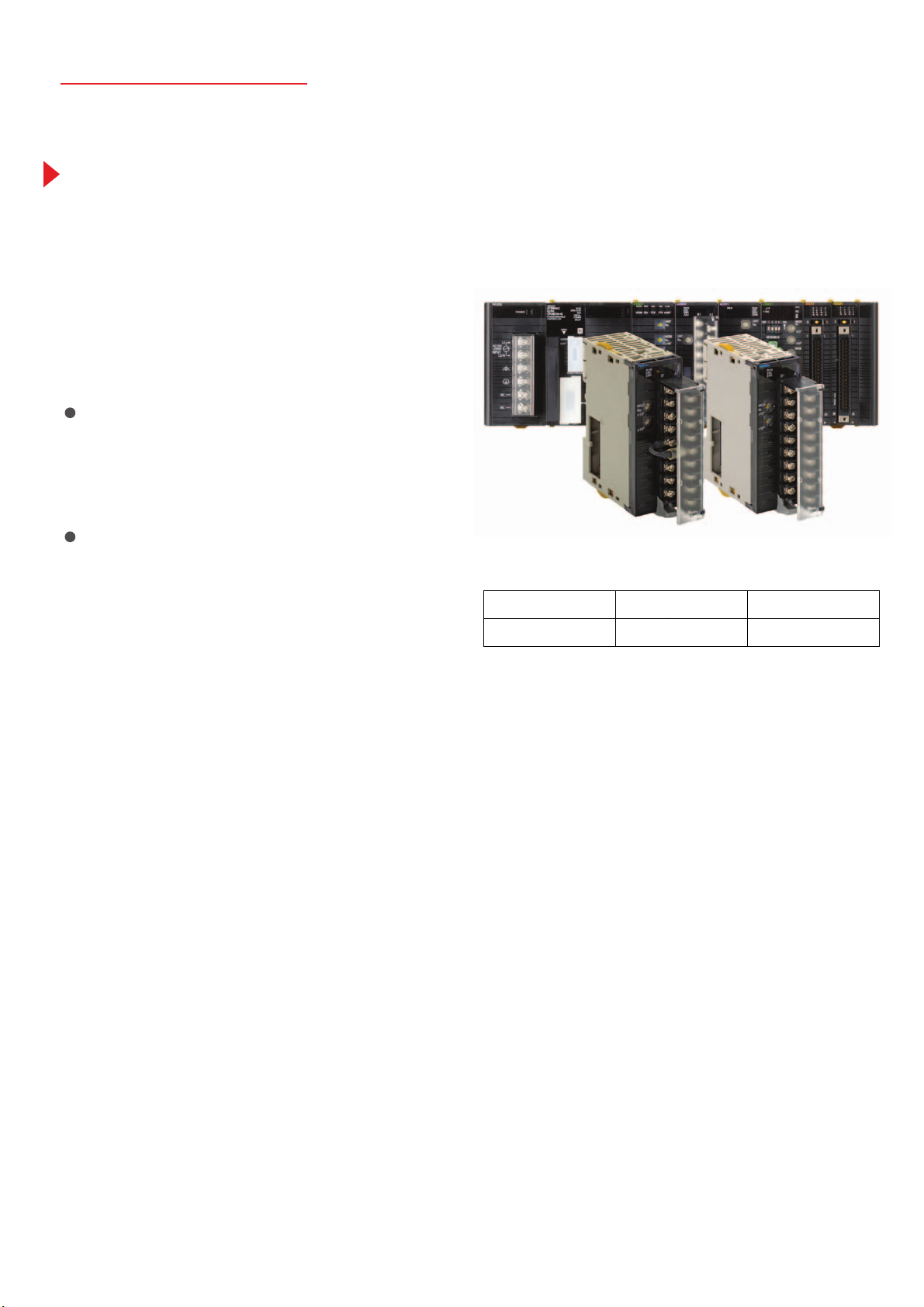
New Products
CJ1W-PH41U Process Analog I/O Unit
(High-resolution Unit with Fully Universal Inputs)
CJ1W-AD04U Process Analog I/O Unit
(General-purpose Unit with Fully Universal Inputs)
A single Unit handles all types of inputs, including
temperature sensor inputs (e.g., thermocouple or
platinum resistance thermometer), analog signal
inputs (e.g., 4 to 20 mA or 1 to 5 V), and
potentiometer inputs.
Fully Universal Inputs, Including Thermocouple
Inputs, Platinum Resistance Thermometer Inputs, and
DC/Voltage Inputs
The input type can be selected for each input channel, saving
space and reducing costs for compact devices that use a mix of
input types. And trouble-free selection of input types improves
inventory control and maintenance.
General-purpose Models for Great Cost Performance
and High-resolution Models for Applications Such as
Semiconductor Production Equipment
These compact CJ-series Units provide four insolated input
channels per Unit. Depending on the application, choose either the
high-resolution CJ1W-PH41U, which provides a selection of
combinations of resolutions and conversion speeds in addition to
a PLC-first 1/1,000°C range (0.000 to 50.000°C, 4-wire Pt100), or the
general-purpose CJ1W-AD04U, which provides superior cost
performance. (See note.)
Note: According to OMRON investigation.
Resolutions and Sampling Speeds for High-resolution Models
Resolution: 1/256,000
60 ms/4 points
Resolution: 1/64,000
10 ms/4 points
Resolution: 1/16,000
5 ms/4 points
9
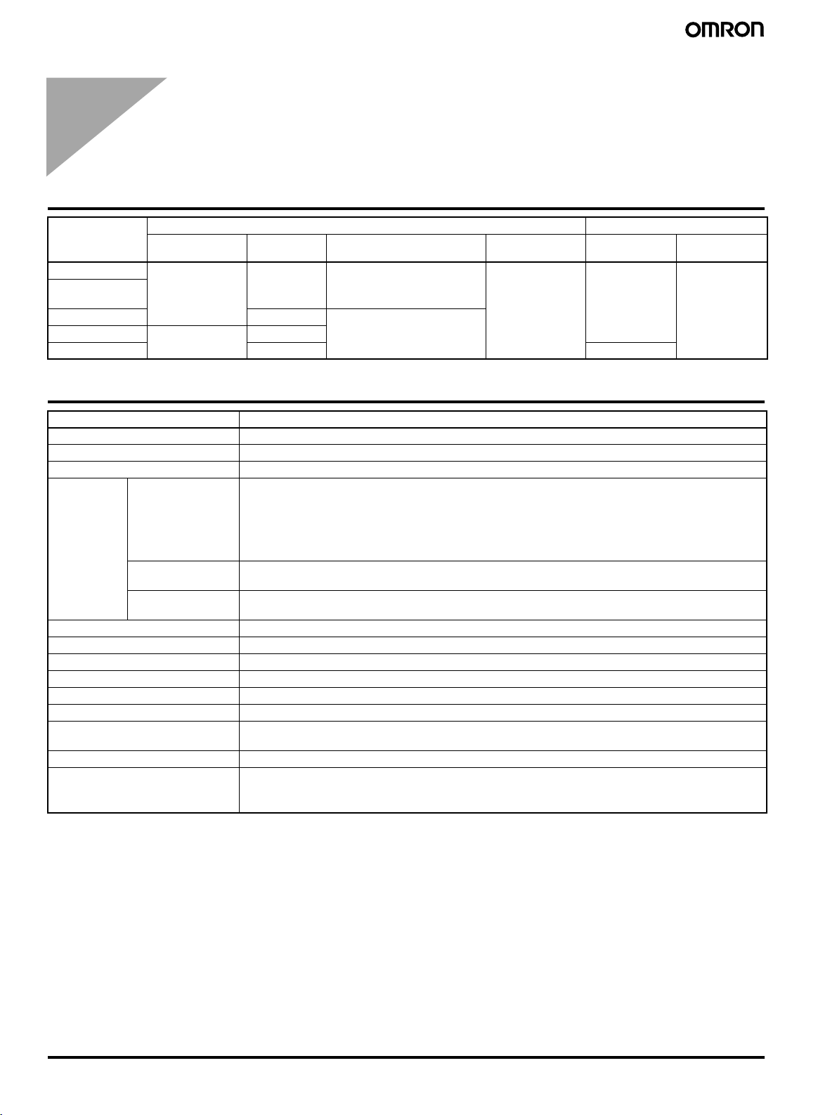
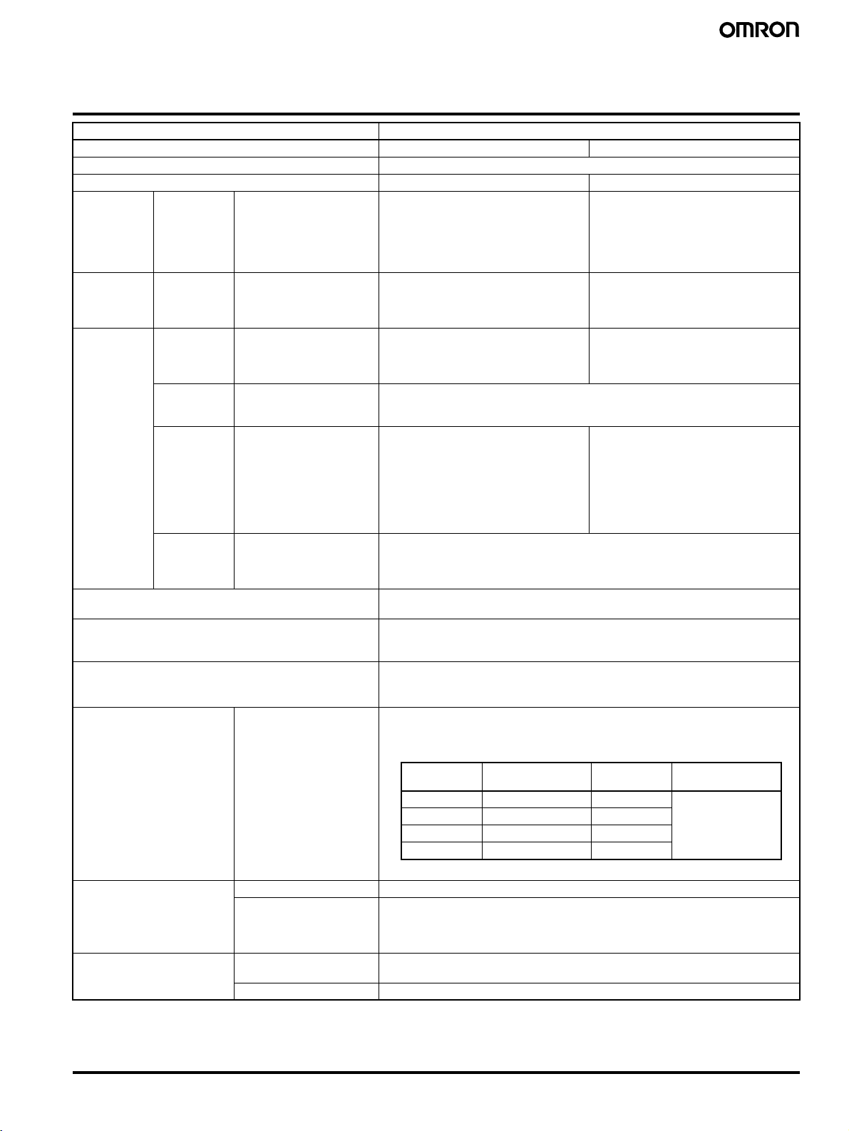
Loop-control CPU Units
Loop-control CPU Units
Loop-control CPU Units
Loop-control CPU Units
Model CPU Unit element Loop Controller
I/O capacity Program
CJ1G-CPU45P 1,280 points
CJ1G-CPU45PGTC
CJ1G-CPU44P 30 Ksteps 64 K words (DM: 32 K words,
CJ1G-CPU43P 960 points (Up to 2
CJ1G-CPU42P 10 Ksteps 50 blocks
(Up to 3 Expansion
Racks)
Expansion Racks)
capacity
60 Ksteps 128 K words (DM: 32 K words,
20 Ksteps
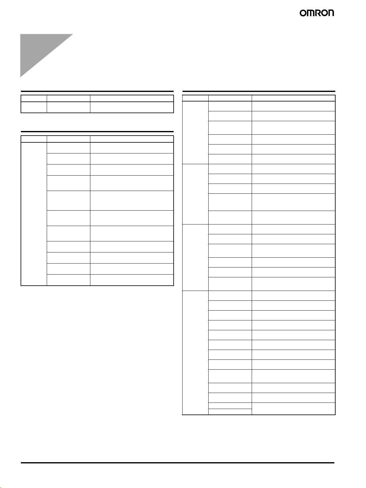
Loop Controller Element Specifications
Item Specification
Name Loop-control CPU Unit
Model Number CJ1G-CPU@@P(-GTC)
Applicable PLCs CJ-series PLCs
Area for data
exchange
with CPU Unit
Settings None
Indicators Two LED indicators: RUN and ready
Super capacitor backup data All function block data (including sequence tables, step ladder program commands), stored error log data
Super capacitor backup time 5 minutes at 25
Data stored in flash memory Function block data
Backup from RAM to flash memory Executed from CX-Process Tool (as required).
Recovery from flash memory to
RAM
Influence on CPU Unit cycle time 0.8 ms max. (depends on function block data contents)
Current consumption (supplied
from Power Supply Unit)
CPU Unit's
Auxiliary Area
User allocations in
I/O Memory
Allocations for all
data
• Loop Controller element-to-CPU Unit element:
Run Status Flag, PV Error Input Flag, MV Error Input Flag, Execution Error Flag, Function Block Database (RAM) Error Flag, Automatic Cold Start Execution Flag, Backup during Operation Flag, Function
Block Changed Flag, etc.
• CPU Unit element-to-Loop Controller element:
Start Mode at Power ON: Hot/Cold Start bit.
User link tables are used to allocate function block ITEM data in any par t of I/O memory in the CPU Unit.
(CIO, Work, Holding, or DM Areas, or EM Area bank 0)
HMI function used to allocate function block ITEM data for Control, Operation, External Controller, and
System Common blocks in the specified bank of the EM Area in the CPU Unit.
Automatically transferred when power to CPU Unit is turned ON if startup mode is set for a cold start, or
executed from CX-Process Tool (as required).
1.06 A for 5 VDC (current consumption for Loop-control CPU Unit including CPU Unit element and Loop
Controller element)
Note: Increased by 150 mA when NT-AL001 Link Adapter is used.
Data memory capacity Programming
EM: 32 K words
EM: 32 K words
°C
× 3 banks)
× 1 bank)
CX-Programmer,
CX-Simulator, etc.
software
Number of
function blocks
300 blocks CX-Process
Programming
software
10
Loop-control CPU Units
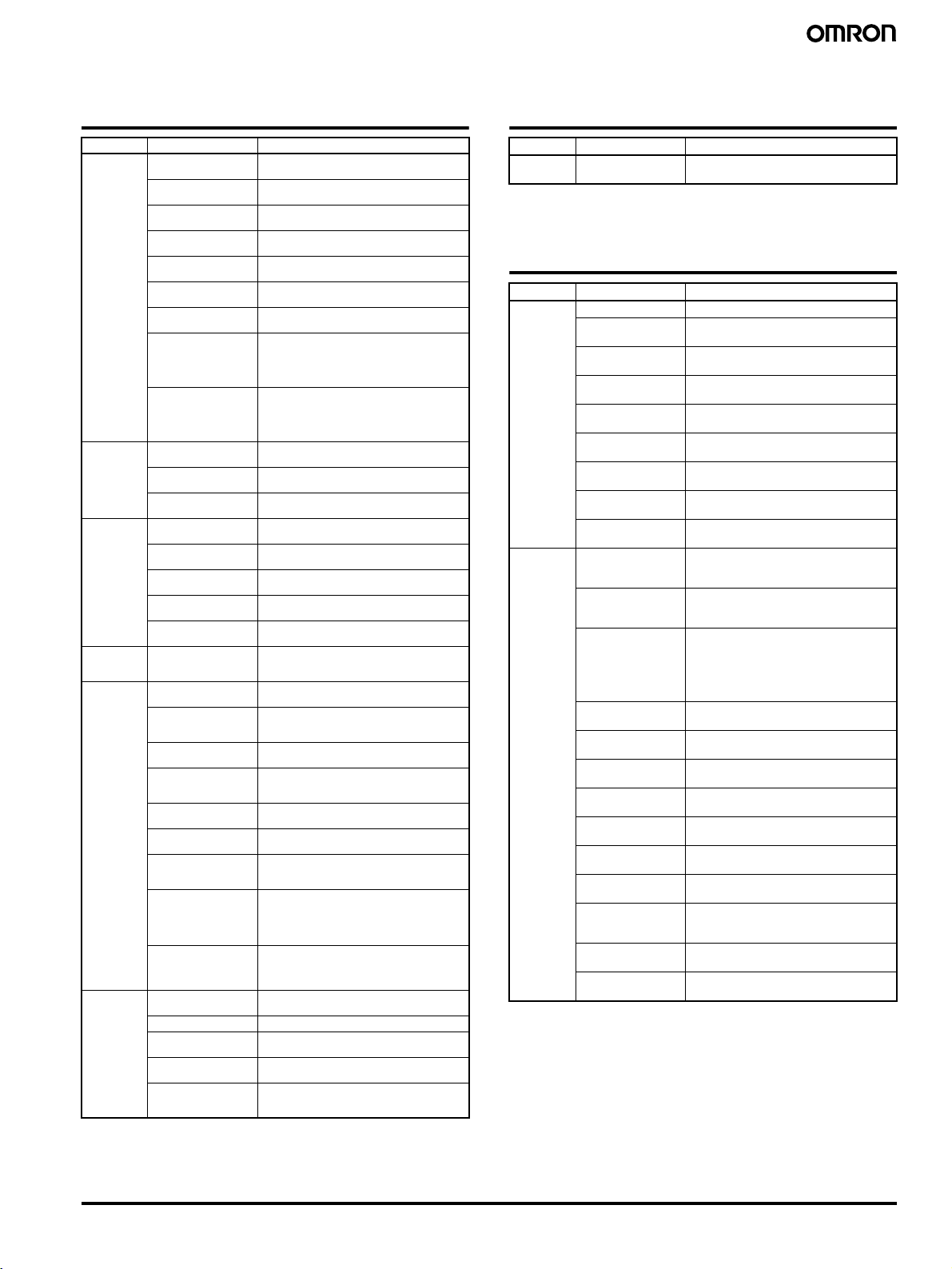
Loop Controller Element Specifications
Loop Controller Element Specifications
Item Specifications
Model CJ1G-CPU42P CJ1G-CPU43/44/45P(-GTC)
Operation method Function block method
Loop Controller element LCB01 LCB03
Function
block analog
operations
Sequence
control
I/O blocks Field terminal
Method for creating and transferring function blocks Created using CX-Process Tool (purchased separately) and transferred to Loop
External I/O response time The time from external input of analog signals up to external output of analog signals
Operation cycle 0.01, 0.02, 0.05, 0.1, 0.2, 0.5, 1, or 2 s (default: 1 s) (See note.)
Internal operation Number of control loops • The maximum number of loops that can be used if the LCB load rate is 80% for a
Control and
operation
blocks
Step ladder
program
blocks
blocks
User link
tables
HMI function I/O function for the speci-
System
Common
block
PID and other control
functions, square root operation, time operations,
pulse train operation, and
other operation functions
for various processes.
Logic sequence and step
sequence functions
Analog I/O function with
Analog I/O Unit, contact
I/O function with Basic I/O
Unit
Analog data I/O and contact data I/O function for
CPU Unit
fied bank of the EM Area
in the CPU Unit for function block ITEM data used
for Control, Operation,
External Controller, and
System Common blocks
for the HMI function.
System common operation cycle setting, run/
stop command, load rate
monitor, etc.
50 blocks max. 300 blocks max.
20 blocks max.
2,000 commands total
100 commands max. per block
Separable into 100 steps max.
30 blocks max. CJ1G-CPU43P: 30 blocks max.
2,400 data items max.
Allocated 1 EM Area bank
Operation and Control blocks:
50 blocks max.
System Common blocks:
20 send/receive words
Single block
Controller.
on a single control loop depends on the function block's operation cycle and the
CPU Unit's cycle time.
Can be set for each function block.
Note: 0.01, 0.02, and 0.05 s cannot be set for some blocks.
standard applications (e.g., with each loop consisting of one Ai4 Terminal, Segment Linearizer, Basic PID, and A04 terminal) is shown in the following table.
× 20 send/receive words
200 blocks max.
4,000 commands total
100 commands max. per block
Separable into 100 steps max.
CJ1G-CPU44/45P: 40 blocks max.
Allocated 1 EM Area bank
Operation and Control blocks:
300 blocks max.
System Common blocks:
20 send/receive words
× 20 send/receive words
Operation
cycle
0.01 s 20 loops 0.2 s 150 loops
0.02 s 35 loops (see note) 0.5 s
0.05 s 70 loops (see note) 1 s
0.1 s 100 loops (see note) 2 s
Note: Loop Controller element LCB01: 25 loops max.
Control method PID control method PID with 2 degrees of freedom
Control combinations Any of the following function blocks can be combined:
Basic PID control, cascade control, feed-forward control, sample PI control, Smith
dead time compensation control, PID control with differential gap, override control,
program control, time-proportional control, etc.
Alarms PID block internal alarms 4 PV alarms (upper upper-limit, upper limit, lower limit, lower lower-limit) and 1
deviation alarm per PID block
Alarm blocks High/low alarm blocks, deviation alarm blocks
Maximum number
of loops
Operation
cycle
Maximum number
of loops
(See note.)
11
List of Function Blocks
List of Function Blocks
System Common Block
System Common Block
Type Block Name Function
--- System Common Makes settings common to all function
blocks and outputs signals for the system.
Control Blocks
Type Block Name Function
Controller 2-position ON/OFF
(See note 1.)
3-position ON/OFF
(See note 1.)
Basic PID
(See note 1.)
Advanced PID
(See note 1.)
Blended PID
(See note 2.)
Batch Flowrate
Capture (See note 2.)
Fuzzy Logic
(See note 2.)
Indication and Setting
(See note 1.)
Indication and Operation (See note 1.)
Ratio Setting
(See note 1.)
Indicator
(See note 1.)
Note: 1. The Function Blocks dealing with high-speed operation
(operation cycle: 0.01, 0.02, and 0.05 seconds is possible).
2. Cannot be used with the CJ1G-CPU45P-GTC.
2-position type ON/OFF controller
3-position type ON/OFF controller for
heating/cooling ON/OFF control
Performs basic PID control.
Performs advanced PID control for
enabling deviation/MV compensation,
MV tracking, etc.
Performs PID control on the cumulative
value (cumulative deviation) between the
accumulated value PV and accumulated
value Remote Set Point.
Functions to open the valve at a fixed opening until a fixed batch accumulated value is
reached.
Outputs up to 2 analog outputs based on
fuzzy logic performed on up to 8 analog
inputs.
Manual setter with PV indication and SP
setting functions
Manual setter with PV indication and MV
setting functions
Ratio and bias setter w ith PV indication and
ratio setting function
PV indicator with PV alarm
Operation Blocks
Type Block Name Function
Alarm/Signal
restrictions/
Hold
Arithmetic Addition or Subtraction
Functions Square Root
Time Function First-order Lag
High/Low Alarm
(See note 1.)
Deviation Alarm
(See note 1.)
Rate-of-change Operation and Alarm
(See note 1.)
High/Low Limit
(See note 1.)
Deviation Limit
(See note 1.)
Analog Signal Hold
(See note 1.)
(See note 1.)
Multiplication
(See note 1.)
Division (See note 1.) Performs division with gain and bias on up to 2
Arithmetic Operation
(See note 1.)
Range Conversion
(See note 1.)
(See note 1.)
Absolute Value
(See note 1.)
Non-linear Gain
(Dead Band)
(See note 1.)
Low-end Cutout
(See note 1.)
Segment Linearizer
(See note 1.)
Temperature and
Pressure Correction
(See note 1.)
(See note 1.)
Rate-of-change Limit
(See note 1.)
Moving Average
(See note. 1)
Lead/Delay (See note 1.) Performs lead/delay operation on single analog
Dead Time (See note 1.) Performs dead time and first-order lag operations
Dead Time Compensation
Accumulator for instantaneous value input
Run Time Accumulator Accumulates the operating time, and outputs the
Time Sequence Data
Statistics (See note 1.)
Ramp Program Ramp program setter for combining ramps for time
Segment Program Segment program setter setting the output values
Segment Program 2 Segment program setting with wait function for
Segment Program 3
Provides the alarm contact outputs for the high
and low limits of single analog signals.
Provides the alarm contact outputs for the deviation of two analog signals.
Provides the alarm contact outputs for the high
and low limits of rate-of-change operation when
the analog signal rate-of-change is output.
Limits the high and low limits of single analog
signals.
Calculates the deviation between two analog
signals, and limits the deviation within that range.
Holds the maximum, minimum or instantaneous
value of single analog signals.
Performs addition/subtraction with gain and bias
on up to 4 analog signals.
Performs multiplication with gain and bias on up to
2 analog signals.
analog signals.
Performs various math operation (trigonometric,
logarithmic, etc.) on floating-point decimal values
converted (to industrial units) from up to 8 analog
inputs.
Easily converts up to 8 analog signals simply by
inputting the 0% and 100% input values and 0%
and 100% output values.
Performs square root extraction (with low end
cutout) on single analog signals.
Outputs the absolute value of single analog signals.
Performs non-linear (3 gain values) operation on
single analog signals. Analog signals can also set
as a dead band (with different gap).
Sets output to zero close to the zero point of single
analog signals.
Converts single analog signals to 15 segments
before the signals are output.
Performs temperature and pressure correction.
Performs first-order lag operation on single analog
signals.
Performs rate-of-change restriction on single
analog signals.
Performs moving average operation on single
analog signals.
signals.
on single analog signals.
Used for Smith's dead time compensation PID
control.
Accumulates analog signals, and outputs 8-digit
accumulated value signals.
pulse signal per specified time.
Records time sequence data from analog signals
and calculates statistics, such as averages and
standard deviations.
and hold values.
with respect to time.
setting the output values with respect to time.
12
List of Function Blocks
Sequence Control
Type Block Name Function
Signal Selection/Switching
Constant
ITEM Setting
Pulse Train
Operation
Others Analog/Pulse Width
Sequence
Operation
Contact Type
Control Target
Rank Selector
(See note 1.)
Input Selector
(See note 1.)
3-input Selector
(See note 1.)
3-output Selector
(See note 1.)
Constant Selector
(See note 1.)
Constant Generator
(See note 1.)
Ramped Switch Switches two analog inputs (or constants) with a
Bank Selector Records the PID parameters (SP, P, I, D, MH, ML)
Split Converter Inputs the MV from the Basic PID block or Ad-
Constant ITEM Setting
(See note 1.)
Variable ITEM Setting
(See note 1.)
Batch Data Collector
(See note 1.)
Accumulated Value Input Adder
Accumulated Value Analog Multiplier
Accumulator for accumulated value input
Contact input/Accumulated value output
Accumulated Value Input/Contact Output
Converter (See note 1.)
Contact Distributor Connect contact signals between function blocks
Constant Comparator
(See note 1.)
Variable Comparator
(See note 1.)
Timer (See note 1.) 2-stage output type addition timer for forecast
ON/OFF Timer
(See note 1.)
Clock Pulse
(See note 1.)
Counter (See note 1.) 2-stage output type addition timer for forecast
Internal Switch
(See note 1.)
Level Check
(See note 1.)
ON/OFF Valve Manipulator
Motor Manipulator Manipulates and monitors motor operation.
Reversible Motor Manipulator
Motor Opening Manipulator
Switch Meter
(See note 2.)
Selects the rank of up to 8 analog signals.
Selects the specified analog signals specified by
the contact signal from up to 8 analog signals.
Selects and outputs one of three analog input
signals.
Outputs one analog input signal in three switched
directions.
Selects 8 preset constants by the contact signal.
Outputs 8 independent constants.
ramp.
in up to 8 sets in advance, and switches the PID
parameter for Basic/Advanced/Blended PID
Blocks according to the analog input range
(zone) or input bits.
vanced PID block, converts the MV into two
analog outputs for V characteristics or parallel
characteristics (e.g., MV for heating or cooling)
and outputs them.
Writes the constant to the specified ITEM at the
rising edge of the send command contact.
Writes the analog signal to the specified ITEM at
the rising edge of the send command contact.
Stores each of max. 8 analog inputs to buffer by
a certain timing within sequential processing.
Adds up to four accumulated value signals.
Multiplies analog signals by the accumulated
value signals.
Converts 4-digit accumulated value signals to 8
digits.
Counts low-speed contact pulses, and outputs
8-digit accumulated signals.
Converts 4-digit accumulated value signals to
low-speed contact pulses before they are output.
Changes the ON/OFF duration ratio in a constant
cycle duration so that it is proportional to the
analog signal.
in a 1:1 connection.
Compares up to eight sets of analog signals and
constants, and outputs the comparison results as
contacts.
Compares up to eight pairs of analog signals,
and outputs the comparison results as contacts.
values and reached values. Can also output the
present value.
Timer for performing ON-OFF operation at preset
ON and OFF times.
Outputs a clock pulse at the setting time interval
for a single operation cycle.
values and arrival values. Can also output the
current va lue.
Temporary storage contact for accepting relays in
the Step Ladder Program block.
Note: (One internal switch is already allocated
as “temporary storage” in CX-Process
To ol .)
Checks an analog input for 8 levels and outputs
a contact corresponding to the level. The level
number is also output as an analog value at the
same time.
Manipulates and monitors ON/OFF valves with
open/close limit switches.
Manipulates and monitors reversible motor
operation.
Inputs a target opening, and manipulates an
electric positional-proportional motor.
Manipulates and monitors multiple (up to 8)
devices such as ON/OFF valves, motors, or
pumps.
Type Block Name Function
--- Step Ladder Program (See note.)
Performs logic sequence and step progression control.
Note: The Function Blocks dealing with high-speed operation (oper-
ation cycle: 0.01, 0.02, and 0.05 seconds is possible).
Field Terminals
Type Block Name Function
Contact
I/O
(See note.)
Analog I/O
(See note.)
Note: The Function Blocks dealing with high-speed operation
DI 8-point Terminal Inputs 8 contacts from 8-point Input Unit.
DI 16-point Terminal Inputs 16 contacts from 16-point Input
DI 32-point Terminal Inputs 32 contacts from 32-point Input
DI 64-point Terminal Inputs 64 contacts from 64-point Input
DO 8-point Terminal Outputs 8 contacts from 8-point Output
DO 16-point Terminal
DO 32-point Terminal
DO 64-point Terminal
DI 16-point/Do
16-point Terminal
AI 4-point Terminal
(PTS51)
AI 4-point Terminal
(PTS52)
AI 2-point Terminal
(PTS15/16, PDC15)
AI 8-point Terminal
(AD081)
AO 8-point Terminal
(DA08V/C)
AI 4-point Terminal
(AD041)
AO 4-point Terminal
(DA041)
AO 2-point Terminal
(DA021)
AI 4-point/AO 2-point
Terminal (MAD42)
AI 4-point Terminal
(DRT1-AD04)
AO 2-point Terminal
(DRT 1-DA02 )
AI 4-point Terminal
(AD04U)
AI 4-point Terminal
(PH41U)
Unit.
Unit.
Unit.
Unit.
Outputs 16 contacts from 16-point Output
Unit.
Outputs 32 contacts from 32-point Output
Unit.
Outputs 64 contacts from 64-point Output
Unit.
Inputs and outputs 16 contacts each from
16-point Input/16-point Output Units.
Inputs 4 analog signals from CJ1WPTS51 (Isolated-type Thermocouple
Input Unit)
Inputs 4 analog signals from CJ1WPTS52 (Isolated-type Temperature Resistance Input Unit).
Inputs 2 analog signals from CJ1WPTS15 (Isolated-type Thermocouple
Input Unit), CJ1W-PTS16 (Isolated-type
Temperature Resistance Input Unit), or
CJ1W-PDC15 (Isolated-type DC Input
Unit).
Inputs 8 analog signals from the CJ1WAD081(-V1).
Outputs 8 analog signals from the CJ1WDA08V/DA08C.
Inputs 4 analog signals from the CJ1WAD041(-V1).
Outputs 4 analog signals from the CJ1WDA041(-V1).
Outputs 4 analog signals from the CJ1WDA021.
Inputs 4 analog signals and outputs 2 analog signals each from the CJ1W-MAD42.
Inputs 4 analog signals from a DRT1AD04 DeviceNet Slave Analog Input Unit.
Outputs two analog signals from a DRT1DA02 DeviceNet Slave Analog Output
Unit.
Inputs 4 analog signals from the CJ1WAD04U.
Inputs 4 analog signals from the CJ1WPH41U.
(operation cycle: 0.01, 0.02, and 0.05 seconds is possible).
Note: 1. The Function Blocks dealing with high-speed operation
(operation cycle: 0.01, 0.02, and 0.05 seconds is possible).
2. Cannot be used with the CJ1G-CPU45P-GTC.
13
 Loading...