

Page 1

CS1 Series, C200HX/HG/HE, C200HS, C200H
C200H-MC221
Motion Control Unit
Specification Sheets
Page 2
Product Specifications
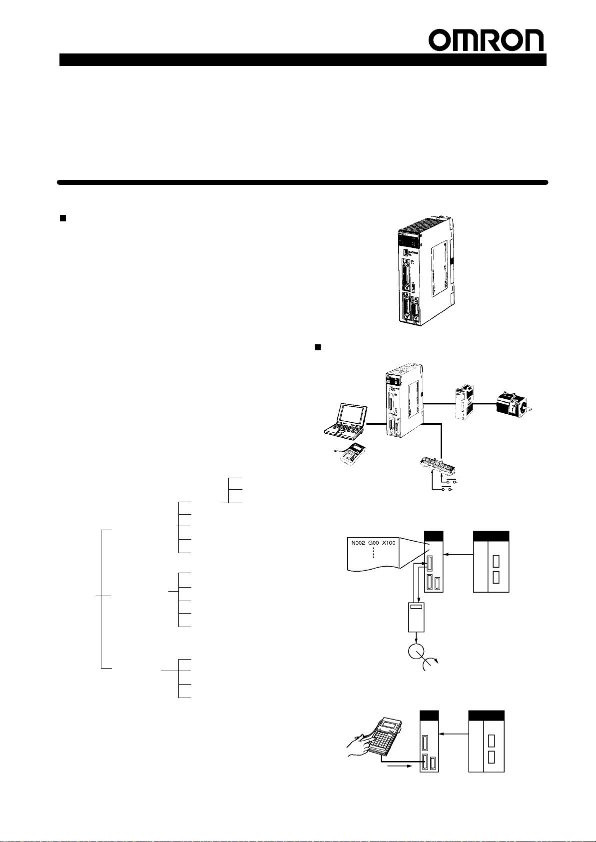
C200H Special I/O Unit
CS1 Series, C200HX/HG/HE, C200HS, C200H
Motion Control Unit
C200H-MC221
2-axis Motion Control with Multitasking G Language
The
C200H-MC221 is a 2-axis Motion Control Unit
for
the CS1-series, C200HX/HG/HE, C200HS, and
C200H
ming, it can be used for advanced motion control,
and its multitasking capability allows operations to
be performed independently for each axis. The
following two modes can be used for motion
control:
1. Motion control by G language programming in the MC Unit
2. Motion control by instructions from the PC interface area in
The
plications
Note: The
MC Unit
functions
PCs. With its built-in G-language program
(Automatic
the
(Manual
MC Unit has been developed for use in simple positioning ap
S Conveyor Systems: X/Y tables, palletizers/depalletizers,
S Assembling
circular interpolation, or helical circular interpolation with
horizontal
it does not support coordinate conversions. The MC Unit
can,
Mode)
CPU Unit or by manual commands from the T
Mode)
using servomotors. Applicable machines are as follows:
loaders/unloaders,
robots),
simple automated assembling machines (such as
coil
winding, polishing, hole punching), etc.
MC Unit is not designed to perform linear interpolation,
articulated robots or cylindrical robots,
however
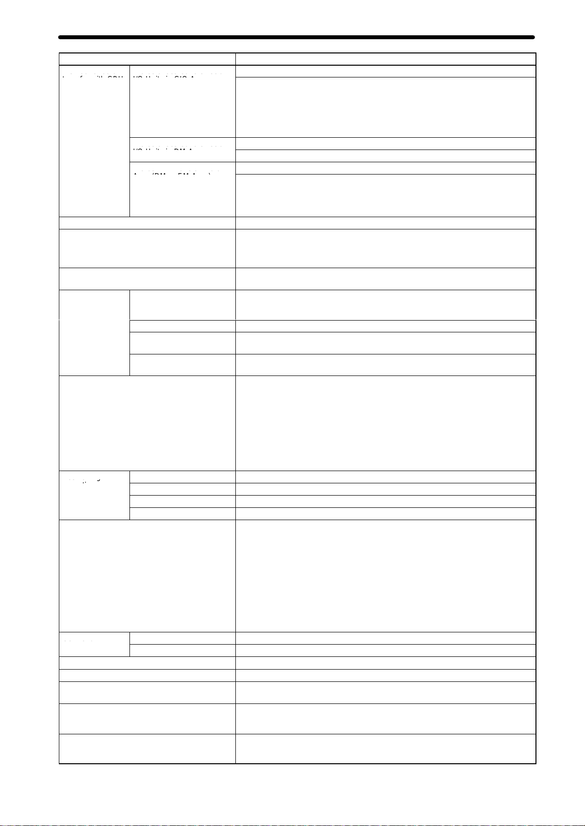
Automatic Mode
(Executes
G-language
programs in the
MC Unit.)
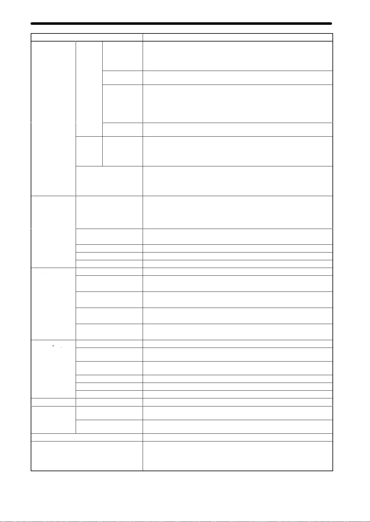
Manual Mode
(Executes manual
commands from
the CPU Unit or
T
eaching Box.)
etc.
Systems: Simple
, perform PTP control with these robots.
robots (including orthogonal
Position
control
Speed control
Origin search
Interrupt feeding
Arithmetic operations, etc.
Jogging
Deceleration stop
Present position preset
Origin search (manual)
Servo lock, etc.
eaching
Box
because
Stop Mode
Pass Mode
Dwell timer
-
-
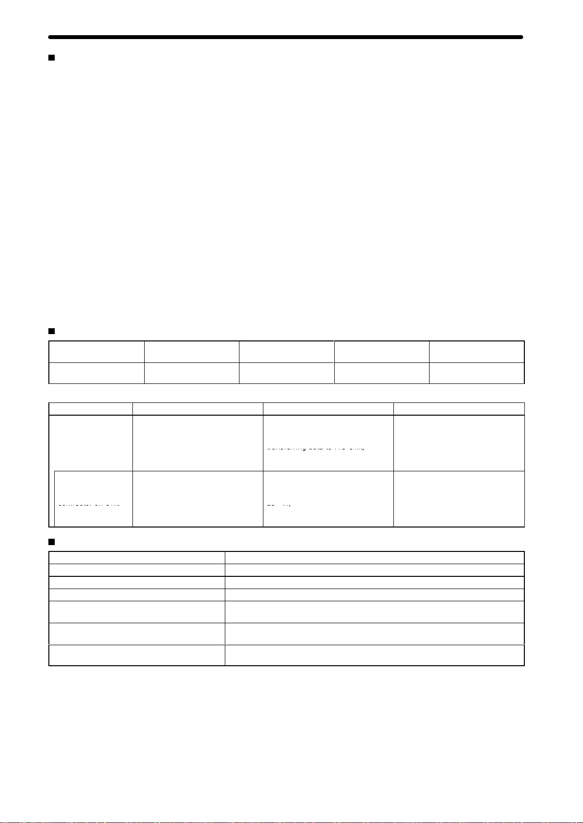
System Configuration
MC Support
Software
Automatic Mode
G language program
Teaching Box
MC Unit
C200H-MC221
Analog input
servodriver
MC Terminal Block
Conversion Unit
Data bits
Operating
commands
Servomotor
CPU Unit
Common to
Automatic and
Manual Modes
“Programmable Controller” is abbreviated as “PC” in these
Teaching
Zones
Backlash correction
Override
Manual Mode
Specification Sheets.
Teaching Box
Manual controls
Data bits
Manual
controls
CPU UnitMC Unit
1
Page 3
Motion Control Unit
osition data, creating MC
transferring data to MC Unit,
(
y)
(connects to
Unit end: half- itch 20- in
D09-9F25F (Sanwa Su ly)
connector on Unit
25 in)
Features
Multitasking
The MC Unit is provided with a multitasking G language, an ideal
language
• Multiaxis
• Position control can be performed by specifying program
numbers using the PC interface area and executing operation
commands, reducing the workload on the CPU Unit’s ladder
program.
• Axis configuration can be set, such as controlling X-Y robot
operations
Up to 16 Axes Can be Controlled for Each CPU Unit
Up
to 8 MC Units can be mounted to a CPU Unit, so up
can
be controlled.
High-speed Response to Start Commands from CPU Unit
The
response time from when a start
CPU
12 ms.
Operation Can be Started or Stopped by General-purpose
Inputs
The
MC Unit is provided
can be started or
Unit.
• General-purpose inputs can be used as jog start signals,
external device interlock signals, restart signals, and other
signals.
G Language to Reduce CPU Unit Programming
for motion control. Up to 100 programs can be registered.
control programs can be easily created.
or controlling operations separately for each axis.
to 16 axes
command is received from the
Unit until the command voltage is output from the MC Unit
with general-purpose inputs, so operation
stopped without needing intervention by the CPU
Models
Applicable PCs
CS1, C200HX/HG/HE
C200HS, C200H
Unit classification
C200H Special I/O Unit
Number of controlled
2 axes
Product Specifications
• The MC Unit can perform high-speed-response positioning by
itself.
Interrupt
The
tions (such as for feeders) by external sensors.
Compatible with Absolute Encoders
This
motors with absolute encoders. It no longer requires origin
searches, and allows quick start and reset at system start-up or
power-down. The MC Unit can also handle a mixture of absolute
and
250-kp/s Encoder Response Frequency
The maximum feedback encoder response frequency is 250 kp/s,
so
vomotors.
is
Data
In
the MC Support Software, it is possible to create position data by
using
machinery.
Operate with MPG
Positioning
MPG
Special Cable for Connecting Servodrivers
axes
Feeding Function Provided as Standard
MC Unit can perform
MC Unit is compatible with OMNUC U-series and other Servo
incremental encoders.
the MC Unit can be used with high-speed and high-precision ser
Creation Using T
addition to entering numbers
the T
eaching Box to teach positions while actually moving
and simple sync operations can be performed using
(manual pulse generator).
Controlled servodriver
Analog input servodriver
high-speed positioning for feeding opera
eaching Box
in the Position Data Edit Window of
the
an
Model
C200H-MC221
-
-
-
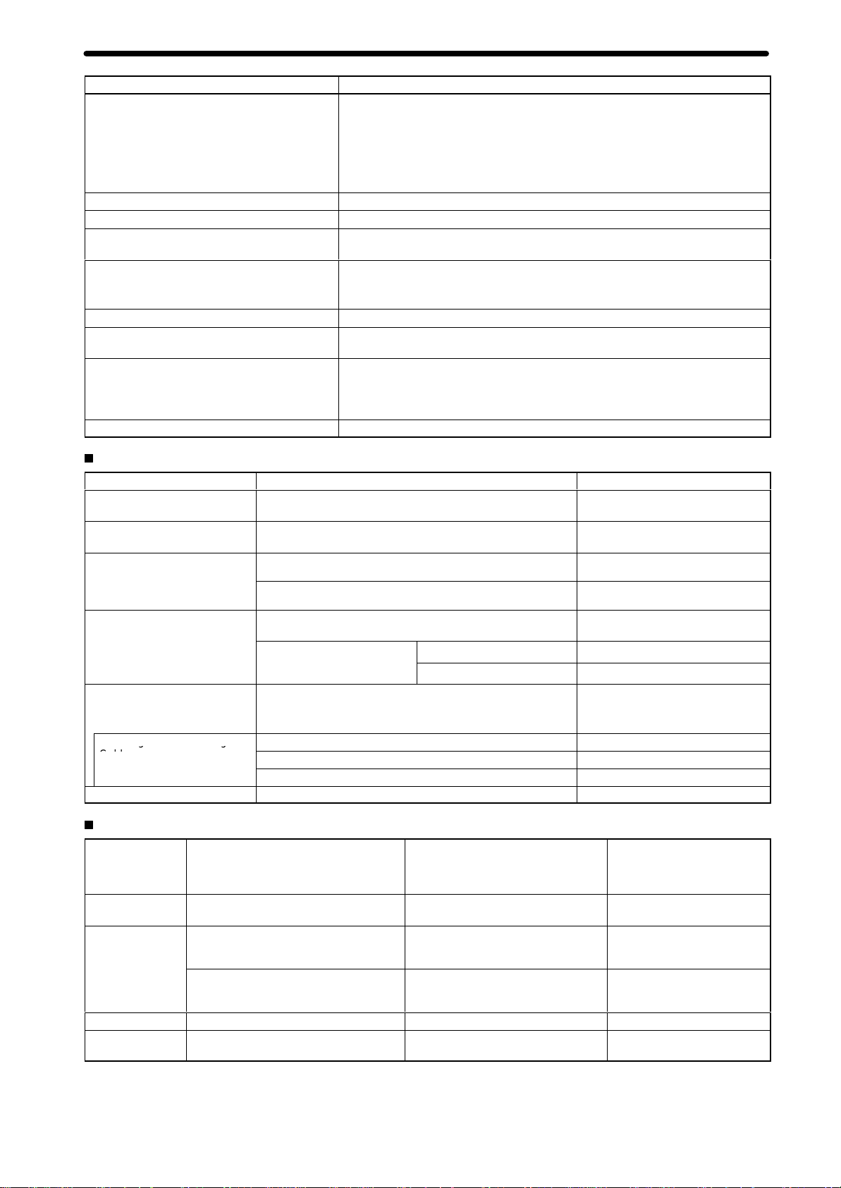
MC Unit Support Software (Sold Separately)
Name Computer Specifications Model
MC
Support Software
RS-422 Cable
connects to
peripheral
connector on Unit
front panel)
IBM PC/A
IBM PC/A
T or compatible
T or compatible
Specifications
Item Specifications
Model
number
Applicable PC
Unit classification
Racks on which MC Unit can be mounted
Maximum number of MC Units that can be
mounted
Unit numbers
CS1-series, C200HX/HG/HE, C200HS, C200H
C200H Special I/O Unit
CPU Rack, C200H Expansion I/O Rack, CS1 Expansion Rack, SYSMAC BUS
Remote I/O Slave Rack
8 Units (16 axes) or 5 Units (10 axes) depending on the PC model. (For details,
refer to
o to 8 and A to E, or 0 to 8 depending on the PC model. (For details, refer to
Connectable CPU Unit Models
Editing system parameters, editing
position data, creating MC
programs (G language),
transferring data to MC Unit,
monitoring MC Unit, saving data in
flash memory
Cable: 3.3 m (connector on MC
Unit end: half-pitch 20-pin,
connector on computer end: D-sub
25-pin)
25-to-9-pin conversion connector
manufactured by Sanwa Supply
Connectable CPU Unit Models
, and printing
,
C200H-MC221
.)
CV500-ZN3AT1-E
CV500-CIF01
D09-9F25F (Sanwa Suppl
.)
2
Page 4
Product Specifications
e od o da a
o ds a oca ed o S ec a
o ds a oca ed o S ec a
ods a so aa
os o g
Co o u
Method for data
transfer with CPU
Unit
Controlled servodrivers Analog input servodrivers (Example: OMRON OMNUC H, M, or U Series)
Encoder interface
Built-in program language
Control
Automatic/Manual Mode (for each task)
Positioning
operations
Position specification method Operating positions can be specified in MC programs by using one of the following
Control unit
Maximum command value
Acceleration/deceleration curve
Acceleration/deceleration time
Speed reference
Feed rate (PTP operation) specification method
Motion Control Unit
Model
number
W
ords allocated to Special
I/O Units in CIO Area
W
ords allocated to Special
I/O Units in DM Area
W
ords in Expansion Data
Area (DM or EM Area)
Control method
Number of controlled axes
Number of simultaneously
controlled axes
PTP (independent) control Multitasking can be used to execute independent operating modes and programs for
Independent
Linear interpolation
Circular interpolation
Interrupt feeding
Minimum setting unit
Units
20 words/Unit (uses 2 unit numbers.)
CPU Unit to MC Unit:
Program numbers, cycle start (MC program operation command), origin search
command, automatic/manual mode switching, etc.
MC Unit to CPU Unit:
Status: Positioning completed, zones, busy flag, etc.
Monitor data: Present position, error codes, M codes, etc.
2 words used out of 100 words allocated
Expansion Data words are specified in initial settings.
23 words per Unit
CPU Unit to MC Unit:
Data transfer area specifications, present position preset values, etc.
MC Unit to CPU Unit:
System error codes, task error codes, ef
Line receiver input; maximum response frequency: 250 kp/s (before multiplication)
Pulse ratio: 4 (fixed)
Note: The applicable absolute encoder is the OMRON OMNUC U Series.
G language (Started by receiving a start command from the CPU Unit ladder
diagram program.)
Speed reference voltage output-type semi-closed loop system, using incremental
and absolute encoder inputs (automatic trapezoidal or S-curve
acceleration/deceleration method)
2 axes max.
2 axes max.
each axis.
Automatic Mode: Mode for executing MC program created in G language.
Manual Mode: Mode for executing manual commands from CPU Unit (PC interface
area) or T
Note: The Automatic and Manual Modes are switched according to the PC interface
area of the CPU Unit.
There are a total of 10 Manual Mode commands, including origin search, reference
origin return, jogging, and present position preset.
The operation command (cycle start) is started in Automatic Mode using the PC
interface area of the CPU Unit.
Independent operations for a maximum of two axes
Linear interpolation for a maximum of two axes
Circular interpolation for a maximum of two axes on a plane.
Operations for each axis
three methods.
Direct Specification of Coordinate V
Example: When G00 X100 is specified with absolute specification, the X axis moves
to a position of 100.
Address Specification of Position Data
Example: When G00 XA0000 is specified, the axis moves to the position set as
position data address 0000.
Indirect Register Specification
Example: When G00 X(E00) is specified, the X axis moves to the position set as the
position data address in the E00 indirect register
1, 0.1, 0.01, 0.001, 0.0001
mm, inch, degree, pulse (There is no unit conversion function.)
–39,999,999 to +39,999,999
T
Individual acceleration/deceleration settings possible: 0 to 9,998 ms (2-ms
increments)
Speed control for a maximum of two axes.
When the unit is pulses, the setting range is from 1 p/s to 1,000 kp/s (after
multiplication by 4).
Can be set for each axis.
Feed rate = High speed × Override value/100
Real-time speed can be changed by altering the override value.
eaching Box.
rapezoidal or S-curve (Can be selected for each axis.)
C200H-MC221
fective program numbers, etc.
alues
.
3
Page 5
Motion Control Unit
sco o
as og a
Model
number
External I/O
Feed operations
Axis control
T
ask program
management
Auxiliary function
Saving program
data
Self-diagnostic function
Error detection functions
Input
Output Servodriver
Peripheral device
Maximum rapid feed rate
Maximum interpolation feed
rate
Rapid feed override
Interpolation feed override 0% to 199.9% (Setting unit: 0.1%)
Jog feed override
Zone settings
Backlash correction Backlash for mechanical system
In-position zone
Position loop gain
Position loop feed-forward
gain
Number of tasks
Number of programs
Program capacity
Position data capacity
Number of registers
Subroutine nesting
M code
MC Unit
External peripheral devices
Individual axis
control
Servodriver
relationships
Encoder
Generalpurpose inputs
relationships
Product Specifications
C200H-MC221
The following signals are each provided for two axes:
CCW limit inputs
CW limit inputs
Origin proximity inputs
Emergency stop inputs
The following signal is provided for two axes:
Driver alarm signal
Line receiver inputs
For two axes
250 kp/s max. before multiplication
Fixed at
Note: When using a manual pulse generator (MPG), connect it to the Y
input terminal. (X-axis + MPG)
2 points (for external start commands, etc.)
The following signals are each provided for two axes:
Speed command voltage output (±10 V)
Operation command output
SEN signal (for absolute encoder)
Driver alarm reset signal
1 serial channel for T
slide switch on the front panel)
T
MS Support Software: 9,600 bits/s for RS-422 and RS-232C
Maximum feed rate for PTP operation
36.86 m/min under the following conditions:
Encoder resolution: 2,048 p/r
Motor speed: 4,500 r/m
Control unit: 0.001 mm/pulse
Maximum feed rate for interpolation operations
36.86 m/min under the same conditions as above
0% to 100.0% (Setting unit: 0.1%)
0% to 100.0% (Setting unit: 0.1%)
Up to 8 zones/axis can be set.
Can be set from 0 to 999 pulses.
Number of accumulated pulses for determining the positioning completed status
Can be set from 0 to 999 pulses.
Servo system response adjustment gain
5 to 250 (1/s)
Servo system response adjustment gain
0% to 100%
2 max. (program execution units)
When 1 task is used:
When 2 tasks are used:
When 1 task is used: 800 blocks max.
When 2 tasks are used: 400 blocks max./task
2,000 positions max. (when only one axis is used) (A0000 to A1999)
32 (Mainly used for specifying position data numbers.) (E00 to E31)
5 levels max.
000 to 999
MC programs, system parameters, and position data can be stored in the flash
memory in the MC Unit.
MC Support Software can be used to save data to a floppy disk or the hard disk at
the personal computer
Memory corruption is detected.
Error counter warning, error counter over
errors, communications errors (T
software limit over error, phase-Z error
error
detection
×4
eaching Box or MC Support Software (switchable using the
eaching Box: 9,600 bits/s for RS-422
100 max.
50 max./task
.
, absolute encoder error detection, CPU
eaching Box), flash memory error
, overtravel, emergency stop, unit number
, driver alarm detection, driver reverse wiring detection, CPU Unit error
, EEPROM error,
-axis encoder
4
Page 6
Product Specifications
Servodriver connector on Unit
eac g o Co ec g
Model
number
Settings
Indicators
Connectors on front panel
Internal current consumption (supplied from
Power Supply Unit)
Dimensions
W
eight (Connectors excluded)
Safety standards
Standard accessories
Cat No.
Motion Control Unit
C200H-MC221
The following switches are located on the front panel.
Rotary switch: Unit number setting (0 to 8, A to E)
Slide switch: Peripheral selection switch (used for determining whether to connect
the peripheral connector to T
The following switch is located on the rear panel.
DIP switch: Absolute encoder default setting function, software switch
enabled/disabled, T
6 LED indicators: Running, error
Servodriver connector
650 mA or less at 5 VDC (with T
200 mA or less at 24 VDC
130.0 × 34.5 × 100.5 mm (H × W × D) Single-slot size
Note: The height including the Backplane is 200 to 240 mm when the attached
connector and the recommended cable are used.
500 g max.
Conforms to UL (Class 2), CSA (Class 2), and EC directives (EMC directive,
low-voltage directive).
10126-3000VE snap-on connector for Servodrivers and 10326-42F0-008 connector
cover (manufactured by Sumitomo 3M): 1 set
Peripheral connector (10120-3000VE 20-pin connector and 10320-42F0-008
connector cover manufactured by Sumitomo 3M): 1 set
Introduction: W314, Details: W315 (suf
eaching Box Japanese/English mode switching
eaching Box or MC Support Software)
, motor rotation direction (CCW/CW)
, I/O connector
, peripheral connector (one each)
eaching Box connected: 850 mA or less)
fixes omitted)
Options (Sold Separately)
Name Specifications Model
MC Terminal Block Conversion
Unit
MC T
erminal Block Conversion
Unit Cable
Snap-on connector for
Servodriver connector on Unit
front panel (1 set provided as
standard on this Unit)
RS-232C cable and connector
for MC Support Software
T
eaching Box
T
eaching Box Connecting
Cable
ROM Cassette --- CVM1-MP702
For easier wiring of I/O connectors
For connecting the I/O connectors on the front panel of the
Unit
Soldered connector
Connector cover
Recommended cable
Peripheral connector on Unit
p
front panel (1 set provided as
standard on this Unit)
Jogging, origin search, present value monitoring, and other
operations by means of manual commands
T
eaching (taking present values into position data)
Cable length: 2 m
Cable length: 4 m
Cable length: 6 m
p
Soldered connector
Connector cover
XW2B-20J6-6
XW2Z-100J-F1
10126-3000VE (Sumitomo 3M)
10326-42F0-008 (Sumitomo 3M)
CO-DS-IREVV
(Hitachi Cable)
10120-3000VE (Sumitomo 3M)
10320-42F0-008 (Sumitomo 3M)
CVM1-PRO01-E
CV500-CN224
CV500-CN424
CV500-CN624
Applicable CPU Units
PC CPU
CS1-series CS1H-CPUjj
C200HX/HG/HE
C200HS C200HS-CPU01(-j)/21(-j)/31/03/23/33
C200H C200H-CPU01/02/03/11/21/22/23/31
CS1G-CPUjj
C200HE-CPU1
C200HG-CPU33/43 (-ZE)
C200HX-CPU34/44 (-ZE)
C200HG-CPU53/63 (-ZE)
C200HX-CPU54/64 (-ZE)
C200HX-CPU65-ZE/85-ZE
Unit model
1/32/42 (-ZE)
T
otal number of MCUs that can be
mounted on CPU Units, Expansion
I/O Racks, and SYSMAC BUS
Remote I/O Slave Racks (see note)
8 (unit numbers 0 to 8 and A to E)
5 (unit numbers 0 to 8)
8 (unit numbers 0 to 8 and A to E)
5 (unit numbers 0 to 8)
5 (unit numbers 0 to 8)
Unit location restrictions
None
None
None
None
Cannot be mounted to two
rightmost slots on CPU Rack.
-SX-10P × 0.18 mm
2
Note:
Restrictions on SYSMAC BUS Remote I/O Slave Racks
The
maximum number of C200H Special I/O Units that can be mounted
on a SYSMAC BUS Remote I/O Slave Unit dif
fers according to
5
Page 7

Motion Control Unit
the
Unit type as shown below
of
Units that can be mounted.
Group A B C D
Units
Maximum number of
Units that can be
mounted in each group
under one Master
Maximum number of
Units that can be
mounted in all groups
. C200H Special
ASCII Unit,
High-speed Counter
Unit, Position Control
Unit
(NC111/112/113/213),
Analog I/O Unit, ID
Sensor Unit, Fuzzy
Logic Unit
4 Units 8 Units 6 Units 2 Units
3A + B + 2C + 6D x 12, and A + B + C + D
I/O Units can be divided into the following four groups according to the maximum number
Multipoint I/O Unit,
T
emperature Control
Unit, PID Control Unit,
Heating/Cooling
Control Unit, Cam
Positioner Unit
T
emperature Sensor
Unit, Voice Unit
x 8
MC Unit Functions and Execution Methods
The
MC Unit functions can be executed using either of the following three methods.
1.
Using MC programs (G language)
2.
Specifying functions from the CPU Unit to the MC Unit through the PC interface area
3.
Specifying system parameters by using MC Support Software, IOWR instructions, or I/O transfer bits
Function
MC program (G language)
Positioning with linear
interpolation
Positioning with circular
interpolation
Speed control
Interrupt feeding
Switching to Pass Mode
Switching to Stop Mode
Dwell timer setting/execution
In-position setting
W
orkpiece origin return
Position loop gain setting
Cycle start --Single block
Pause --Forced block end
Origin search
Reference origin return
Override setting
Error counter reset
Driver alarm reset
M code reset
Teaching --Jogging --Deceleration stop
Forced origin
Absolute encoder origin setting
Servo-lock --Servo-unlock --Trapezoidal/S-curve
specification
Zone settings
Backlash correction setting --- --Origin deceleration method
(G01) (Automatic Mode)
(G02/03) (Automatic Mode)
(G30) (Automatic Mode)
(G31) (Automatic Mode)
(G10) (Automatic Mode)
(G1
1) (Automatic Mode)
(G04) (Automatic Mode)
--- --(G27) (Automatic Mode)
--- ---
---
--(G28) (Automatic Mode)
(G26) (Automatic Mode)
---
---
---
---
---
---
---
--- ---
--- ---
--- ---
Execution methods
(Modes in parentheses: V
PC interface area
--- ---
--- ---
--- ---
--- ---
--- ---
--- ---
--- ---
--- ---
(Automatic Mode)
(Automatic Mode)
(Automatic Mode)
(Automatic Mode)
(Manual Mode)
(Manual Mode)
(Automatic/Manual Mode)
(Automatic/Manual Mode)
(Automatic/Manual Mode)
(Automatic Mode)
(Automatic/Manual Mode)
(Manual Mode)
(Manual Mode)
(Manual Mode)
(Manual Mode)
(Manual Mode)
(Manual Mode)
Product Specifications
Position Control Unit
(NC21
1/413), Motion
Control Unit
alid modes)
System parameters
(Automatic/Manual Mode)
(Automatic/Manual Mode)
---
---
---
---
---
---
---
---
---
---
---
---
---
---
---
---
--(Automatic/Manual Mode)
(Automatic/Manual Mode)
(Automatic/Manual Mode)
(Automatic/Manual Mode)
6
Page 8

Product Specifications
G Language
Motion Control Unit
Example
N000 P001 XY
Program number and axis declaration
N001 G91
N002 G00 X100 Y50 M001
Code Name Function
G00 Positioning
G01
G02
G03
G04
G10
G11
G17
G26
G27 W
G28
G29 Origin UNDEFINED
G30 SPEED CONTROL
G31 INTERRUPT FEEDING
G50
G51
G53
G54
G60
G63 Substitution
G69
G70
G71
G72
G73
G74
G75
G76
G79
G90
G91
Linear Interpolation
Circular Interpolation (Clockwise)
Circular Interpolation
(Counterclockwise)
Dwell T
imer W
Pass Mode
Stop Mode
Circular Plane Specification (X-Y)
Reference Origin Return
orkpiece Origin Return
Origin Search
Select Reference Coordinate System Specifies the reference coordinate system.
Select W
Change W
Change Reference Coordinate
System PV
Arithmetic Operations
Change Parameter Changes the acceleration/deceleration time.
Unconditional Jump
Conditional Jump
Subroutine Jump
Subroutine End
Optional End
Optional Skip Skips the block after this command when the specified optional input is ON.
Optional Program Stop
Program End
Absolute Specification Positions with absolute coordinates when performing axis operations.
Incremental Specification
orkpiece Coordinate System
orkpiece Origin Of
fset
G code: 2-digit number following “G” represents the command.
Incremental Specification
Positioning: Moves the X axis by 100 and the Y axis by 50
from the present position, and outputs M code 001 after
positioning hs been completed.
Performs positioning according to maximum rapid feed rate × override (%). (PTP
control)
Performs linear interpolation on 1, 2, 3, or 4 axes (1 or 2 axes for MC221).
The specified axes move simultaneously
The feed rate can be specified.
Performs 2-axis circular interpolation in the clockwise direction at the specified
interpolation feed rate.
Performs 2-axis circular interpolation in the counterclockwise direction at the
specified interpolation feed rate.
aits for the specified length of time.
Performs operations one-by-one in sequence without waiting for deceleration to
stop.
Performs the next operation after completing positioning.
Sets the X-Y plane as the plane for circular interpolation.
Moves to the reference origin.
Moves to the workpiece origin.
Performs an origin search on the specified axis.
Sets the origin to an undefined state.
Feeds up to 2 axes simultaneously at the controlled feed rate.
Performs an interrupt feeding operation.
Specifies the workpiece coordinate system.
Changes the origin of the workpiece coordinate system.
Changes the present value in the reference coordinate system.
Performs arithmetic operations on numerical values, position data, and registers.
Substitutes numerical values, position data, or registers into other position data or
registers.
Unconditionally jumps to the specified block.
Jumps to the specified block when the condition is met.
Calls the specified subroutine.
Ends the subroutine.
Ends the block currently being executed when the specified optional input is ON.
Pauses the program when the specified optional input is ON.
Ends the main program.
Positions with relative coordinates when performing axis operations.
number (N000 to N999): Equivalent to a program line number
Block
.
.
Auxiliary Codes
Code Name Function
M M
code
Outputs an M code.
7
Page 9

Motion Control Unit
System Configuration
Control System
Semi-closed
Feedback pulses and
present value information
(for absolute encoders)
Loop System
Product Specifications
MC Unit
Analog output
Servodriver
Tachogenerator
Rotary encoder
Connected Configuration
DRV X-Y connectors
Input connector
XW2Z-100J-F1 MC
Unit Terminal Block
Cable or
user-prepared cable
Peripheral connector
XW2B-20J6-6 MC Unit
Terminal Block
Servomotor
MC Unit
CPU Unit
Power Supply Unit
Servodriver Connecting
Cable (for U/H/M-series) or
user-prepared cable
MC Support Software
Teaching Box
or
Servodriver
Servomotor
CCW limit input
CW limit input
Origin proximity input
Emergency stop input
for 2 axes
General-purpose inputs (2)
Servodriver
Servomotor
8
Page 10

Product Specifications
Exchanging Data
CS1
CIO Area
to
to
to
to
to
to
to
to
to
to
to
to
to
to
to
DM Area (Essential)
to
to
to
to
to
to
to
to
to
to
to
to
to
to
to
DM Area (Optional)
Optional words
(23 words)
Unit #0
Unit #1
Unit #2
Unit #3
Unit #4
Unit #5
Unit #6
Unit #7
Unit #8
Unit #9
Unit #A
Unit #B
Unit #C
Unit #D
Unit #E
Unit #0
Unit #1
Unit #2
Unit #3
Unit #4
Unit #5
Unit #6
Unit #7
Unit #8
Unit #9
Unit #A
Unit #B
Unit #C
Unit #D
Unit #E
Data is transferred to each Unit
whenever an I/O refresh is
executed.
Data is automatically transferred
to each Unit when power is ON
or the Unit Restart Bit is ON.
Transferred
whenever
necessary
Refreshed once every two to
three cycles.
Motion Control Unit
C200H-MC221
I/O Refresh Data Area
Wd n
to
Wd n+7
Wd n+8
to
Wd n+19
n: 2000 + 10 × unit no.
m
m+1
Wd I
to
Wd I+11
Wd I+12
to
Wd I+22
I: W
Output refresh
Input refresh
20 words are used.
Fixed DM Area (Initial Setting Area)
Specification of Expansion DM Area
First word of Expansion DM Area
2 words are used.
m: 20000 + 100 × unit no.
Expansion Data Area
Output data
Input refresh
23 words are used.
ords specified with m and m + 1.
PC
to
MC
MC
to
PC
Word
Task 1 program no.
Task 1 system control bit
Task 2 program no.
Task 2 system control bit
X-axis override
X-axis control bit
Y-axis override
Y-axis control bit
Error data and system status
Error code
Task 1 M code
Task 1 status
Task 2 M code
Task 2 status
X-axis present position
X-axis status (zone, etc.)
Y-axis present position
Y-axis status (zone, etc.)
Description
X-axis control bit
Bit Bit name
Deceleration stop
Origin search
Reference origin return
Jogging
Not used
Present position preset
Reserved
Reserved
MPG enabled
Servo lock
Servo free
Driver alarm reset
Override set
Jogging direction
MPG multiplication factor 1
MPG multiplication factor 2
9
Page 11

Motion Control Unit
U
Gee
ed
CC
Oa ge
C
Oa ge
Component Names
Product Specifications
LED indicators
Unit number setting switch
DRV X-Y connector
10126-3000VE Connector (Sumitomo 3M)
10326-42F0-008 Connector cover (Sumitomo 3M)
(The Unit is provided with 1 set.)
Peripheral selection switch
I/O connector
Peripheral connector
Indicators
Indicator Color Status Meaning
RUN Green
ERR Red
XCCW
Orange
YCCW
XCW
Orange
YCW
ON Initialization
OFF
ON
OFF
ON
OFF
ON
OFF
An error has occurred in the MC Unit or the CPU Unit.
An error has occurred in the MC Unit.
The MC Unit is operating normally
The motor is rotating counterclockwise.
The motor is rotating clockwise or stopped.
The motor is rotating clockwise.
The motor is rotating counterclockwise or stopped.
has been completed normally
.
. (Connected to the CPU Unit normally
.)
10
Page 12

Product Specifications
External I/O Connections: Input Connector
Pin Symbol Terminal
1
2 XCWL (NC) 11 X-axis CW limit
3 YCWL (NC) 16 Y
4 XCCWL (NC) 12 X-axis CCW
5 YCCWL (NC) 17 Y-axis CCW
6 XSTOP (NC) 14 X-axis
7 YSTOP (NC) 8 Y-axis
8 IN1 (NO) 4
9 IN2 (NO) 9
10 XORG (NC,
11 YORG (NC,
14 DC GND 0
+24 V
NO)
NO)
on
MC Unit
terminal block
10
13
18 Y
Motion Control Unit
Name Function
24-VDC input
input
-axis CW limit
input
limit input
limit input
emergency
stop input
emergency
stop input
General input 1 General input 1
General input 2 General input 2
X-axis origin
proximity input
-axis origin
proximity input
24-VDC input
ground
Connects to the + terminal of the
24-VDC external power supply
Limits movement of the X axis in
the CW direction.
Limits movement of the Y axis in
the CW direction.
Limits movement of the X axis in
the CCW direction.
Limits movement of the Y axis in
the CCW direction.
Disables the X-axis run output
and stops it.
Disables the Y
and stops it.
Used for the X-axis origin search.
Used for the Y
Connects to the – terminal (0 V)
of the 24-VDC external power
supply.
.
-axis run output
-axis origin search.
“NC” stands for normally closed and “NO” stands for normally open.
External Connection Diagram
Using the MC Unit Input Connector
Example:
–
+
X-axis W
24 VDC
iring
CW
limit input
CCW
limit
input
Emergency
stop input
Origin
proximit
y input
Input Connector
Pin No.
24-VDC input
X-axis CW limit input
Y-axis CW limit input
X-axis CCW limit input
Y-axis CCW limit input
X-axis emergency stop input
Y-axis emergency stop input
General input 1
General input 2
X-axis origin proximity input
Y-axis origin proximity input
24-VDC input ground
Connector:
Wire and assemble the connector by using
the connector case provided with the Unit
or by using the XW2Z-100J-F1 MC Unit
T
erminal Block Connecting Cable.
11
Page 13

Motion Control Unit
Using the MC Unit Terminal Block
XW2Z-100J-F1 MC Unit Cable
Example: X-axis wiring
Product Specifications
XW2Z-100J-F1
MC Unit Terminals
24-VDC input ground
XW2B-20J6-6
MC Unit Terminals
XCW, XCCW, origin proximity, and emergency stop
YCW, YCCW, origin proximity, and emergency stop
+
–
24 VDC
CW
limit
input
CCW
limit
input
Emerg
ency
stop
input
General input 1
Origin
proxim
ity
input
Y-axis emergency stop input
General input 2
24-VDC input
X-axis CW limit input
X-axis CCW limit input
X-axis origin proximity input
X-axis emergency stop input
Y-axis CW limit input
Y-axis CCW limit input
Y-axis origin proximity input
12
Page 14

Product Specifications
DRV X-Y Connector: Servodriver Connection
Pin Symbol Name Function
1 +24
2 DC GND
3 XALM
4 XRUN
5 XALMRS
8 XSGND X-axis SEN signal
9 XSOUT X-axis SEN signal
10 X-GND X-axis feedback
11 X-A
12 X-A X-axis phase A
13 X-B
14 X-B X-axis phase B
15 X-Z
16 X-Z X-axis phase Z
17 XOUT
18 XAGND
19 +F24V
20 FDC GND
21 YALM Y
22 YRUN Y
23 YALMRS Y
26 YSGND Y-axis SEN signal
27 YSOUT Y-axis SEN signal
28 Y-GND Y-axis feedback
29 Y-A Y
30 Y-A Y-axis phase A
31 Y-B Y
32 Y-B Y-axis phase B
33 Y-Z Y
34 Y-Z Y-axis phase Z
35 YOUT Y
36 YAGND Y
V
Motion Control Unit
24 VDC input
24 VDC input ground
X-axis alarm input
X-axis run output Driver run output for the X-axis
X-axis alarm reset
output
ground
output
ground
X-axis phase A input
input
X-axis phase B input
input
X-axis phase Z input Phase Z feedback input for the X-axis
input
X-axis speed control
X-axis speed control
ground
24 VDC output
24 VDC output
ground
-axis alarm input
-axis run output
-axis alarm reset
output
ground
output
ground
-axis phase A input
input
-axis phase B input
input
-axis phase Z input
input
-axis speed control
-axis speed control
ground
External power supply’
X-Y axes)
External power supply’
the X-Y axes)
Driver alarm input for the X-axis
Reset output for the X-axis’
SEN signal ground for the X-axis
SEN signal output for the X-axis (absolute
encoder driver)
Feedback ground for the X-axis
Phase A feedback input for the X-axis
Phase A
Phase B feedback input for the X-axis
Phase B
Phase Z
Speed control voltage to the X-axis driver
Ground for the X-axis’
24-VDC input to the driver (for the X-Y axes)
Ground for 24-VDC outputs (for the X-Y axes)
Driver alarm input for the Y
Driver run output for the Y
Reset output for the Y
SEN signal ground for the Y
SEN signal output for the Y
encoder driver)
Feedback ground for the Y
Phase A feedback input for the Y
Phase A
Phase B feedback input for the Y
Phase B
Phase Z feedback input for the Y
Phase Z
Speed control voltage to the Y
Ground for the Y
feedback input for the X-axis
feedback input for the X-axis
feedback input for the X-axis
feedback input for the Y
feedback input for the Y
feedback input for the Y
s 24-VDC input (for the
s 24-VDC ground (for
s driver alarm.
s speed control voltage
-axis
-axis
-axis’
s driver alarm.
-axis
-axis (absolute
-axis
-axis driver
-axis’
s speed control voltage
-axis
-axis
-axis
-axis
-axis
-axis
13
Page 15

Motion Control Unit
Se es
eg ( )
for 30 W to
for 1W to
se es
88
se es
88
r
Servodriver Cables (Optional)
When using OMRON’s U-, H-, or M-series Servodrivers, use Special Servodriver Cables that are
available
as options to connect the MC Unit to Servodrivers.
Series
For two axes
U-series R88D-U
R88A-CPU001M2 R88A-CPU001M1 1.0
for 30-W to
750-W
Servodrivers
R88D-U
R88A-CPU002M2 R88A-CPU002M1 2.0
R88A-CPUB001M2 R88A-CPUB001M1 1.0
for 1-W to
5-kW
Servodrivers
H-series R88D-H
R88A-CPUB002M2 R88A-CPUB002M1 2.0
R88A-CPH001M2 R88A-CPH001M1 1.0
R88A-CPH002M2 R88A-CPH002M1 2.0
M-series R88D-M
R88A-CPM001M2 R88A-CPM001M1 1.0
R88A-CPM002M2 R88A-CPM002M1 2.0
Cable model number
For single axis
Length (m)
Product Specifications
Connector:
When
the Special Cables shown on
the left are not to be used, wire and
assemble the connector by using
the connector case provided with
the Unit.
U-series Servodrivers:
R88A-CPU001M2/002M2
R88A-CPUB001M2/002M2 (1 to 5 kW)
Connect to a battery when using the
absolute encoder.
DRV X-Y
connector
Connect to +24 V
(30 to 750 W)
Servodr
iver
Servodri
ver
H-series Servodrivers:
R88A-CPH001M2/002M2
DRV X-Y
connector
Connect to +24 V
Servodri
ver
Servodr
iver
M-series Servodrivers:
R88A-CPM001M2/002M2
DRV X-Y
connector
Connect to +24 V
Servod
ver
Servodr
iver
14
Page 16

Product Specifications
Connection Examples
Connection
Special Servodriver Cable: R88A-CPU00
to U-series 30-W to 750-W Models (Using an Absolute Encoder)
jM2
MC Unit
DRV X-Y connector
24-VDC input ground
X-axis alarm input
X-axis run output
X-axis alarm reset output
X-axis SEN signal ground
X-axis SEN signal output
X-axis feedback ground
X-axis phase A input
X-axis phase A
X-axis phase B input
X-axis phase B
X-axis phase Z input
X-axis phase Z input
X-axis speed control
X-axis speed control ground
24-VDC output ground
24-VDC input
input
input
24-VDC output
DC Power Supply
Red
+24V
Black
Battery
(+2.8 to 4.5 V)
Motion Control Unit
AC Servodriver
R88D-UAjjj
CN1
+24V
+A
–A
+B
–B
+Z
–Z
Red
+
Black
AC Servodriver
R88D-UAjjj
Dimensions
Note: All
C200H-MC221
units are in millimeters unless otherwise indicated.
Y-axis alarm input
Y-axis run output
Y-axis alarm reset output
Y-axis SEN signal ground
Y-axis SEN signal output
Y-axis feedback ground
Y-axis phase A input
Y-axis phase A
Y-axis phase B input
Y-axis phase B
Y-axis phase Z input
Y-axis phase Z
Y-axis speed control
Y-axis speed control ground
input
input
input
Red
Battery
(+2.8 to 4.5 V)
+
Black
Dimensions with the Unit Mounted
U/H/M-series Servodriver Cable
+24V
+A
–A
+B
–B
+Z
–Z
Dimensions with the Unit Mounted
Unit: mm
ALL DIMENSIONS SHOWN ARE IN MILLIMETERS.
To
convert millimeters into inches, multiply by 0.03937. T
o convert grams into ounces, multiply by 0.03527.
Backplane
200 to 240
15
Page 17

OMRON Corporation
Systems Components Division
66 Matsumoto
Mishima-city
, Shizuoka 41
1-851
Japan
T
el: (81)559-77-9633
Fax: (81)559-77-9097
Regional Headquarters
OMRON EUROPE B.V.
W
egalaan 67-69, NL-2132 JD Hoofddorp
1
The Netherlands
T
el: (31)2356-81-300/Fax: (31)2356-81-388
OMRON ELECTRONICS, INC.
1 East Commerce Drive, Schaumburg, IL 60173
U.S.A.
T
el: (1)847-843-7900/Fax: (1)847-843-8568
OMRON ASIA PACIFIC PTE. LTD.
83 Clemenceau Avenue,
#1
1-01, UE Square,
Singapore 239920
T
el: (65)835-301
1/Fax: (65)835-271
1
Authorized Distributor:
Note:
Specifications subject to change without notice.
Cat.
No. R061-E1-1
Printed in Japan
0100-0.7M
 Loading...