

Page 1

Cat.No. W369–E1–1
SYSMAC
C200HW-ZW3AT2-E-V2
Controller Link Support Software
Ver. 2.00
OPERATION MANUAL
Page 2

SYSMAC
C200HW-ZW3AT2-E-V2
Controller Link Support Software
Ver. 2.00
Operation Manual
Revised March 2000
Page 3

Notice:
OMRON products are manufactured for use according to proper procedures by a qualified operator
and only for the purposes described in this manual.
The following conventions are used to indicate and classify precautions in this manual. Always heed
the information provided with them. Failure to heed precautions can result in injury to people or damage to property.
DANGER Indicates an imminently hazardous situation which, if not avoided, will result in death or
!
serious injury.
WARNING Indicates a potentially hazardous situation which, if not avoided, could result in death or
!
serious injury.
Caution Indicates a potentially hazardous situation which, if not avoided, may result in minor or
!
moderate injury, or property damage.
OMRON Product References
All OMRON products are capitalized in this manual. The word “Unit” is also capitalized when it refers
to an OMRON product, regardless of whether or not it appears in the proper name of the product.
The abbreviation “Ch,” which appears in some displays and on some OMRON products, often means
“word” and is abbreviated “Wd” in documentation in this sense.
The abbreviation “PC” means Programmable Controller and is not used as an abbreviation for anything else.
Visual Aids
The following headings appear in the left column of the manual to help you locate different types of
information.
OMRON, 2000
All rights reserved. No part of this publication may be reproduced, stored in a retrieval system, or transmitted, in any
form, or by any means, mechanical, electronic, photocopying, recording, or otherwise, without the prior written permission of OMRON.
No patent liability is assumed with respect to the use of the information contained herein. Moreover, because OMRON is
constantly striving to improve its high-quality products, the information contained in this manual is subject to change
without notice. Every precaution has been taken in the preparation of this manual. Nevertheless, OMRON assumes no
responsibility for errors or omissions. Neither is any liability assumed for damages resulting from the use of the information contained in this publication.
DOS, Windows and Microsoft C are registered trademarks of Microsoft Corporation.
IBM is a registered trademark of International Business Machines Corporation.
All other product names or company names that appear in this manual are trademarks or registered trademarks of each
respective company.
Note Indicates information of particular interest for efficient and convenient operation
of the product.
1, 2, 3... 1. Indicates lists of one sort or another, such as procedures, checklists, etc.
v
Page 4

TABLE OF CONTENTS
PRECAUTIONS xi. . . . . . . . . . . . . . . . . . . . . . . . . . . . . . . . .
1 Intended Audience xii. . . . . . . . . . . . . . . . . . . . . . . . . . . . . . . . . . . . . . . . . . . . . . . . . . . . . . . . . . .
2 General Precautions xii. . . . . . . . . . . . . . . . . . . . . . . . . . . . . . . . . . . . . . . . . . . . . . . . . . . . . . . . . .
3 Safety Precautions xii. . . . . . . . . . . . . . . . . . . . . . . . . . . . . . . . . . . . . . . . . . . . . . . . . . . . . . . . . . .
4 Application Precautions xii. . . . . . . . . . . . . . . . . . . . . . . . . . . . . . . . . . . . . . . . . . . . . . . . . . . . . .
5 Trademarks xiii. . . . . . . . . . . . . . . . . . . . . . . . . . . . . . . . . . . . . . . . . . . . . . . . . . . . . . . . . . . . . . . .
6 Checking the Contents xiii. . . . . . . . . . . . . . . . . . . . . . . . . . . . . . . . . . . . . . . . . . . . . . . . . . . . . . .
SECTION 1
Features 1. . . . . . . . . . . . . . . . . . . . . . . . . . . . . . . . . . . . . . .
1-1 About the Controller Link Support Software 2. . . . . . . . . . . . . . . . . . . . . . . . . . . . . . . . . . .
1-2 Checking Components 7. . . . . . . . . . . . . . . . . . . . . . . . . . . . . . . . . . . . . . . . . . . . . . . . . . . .
1-3 Operating Environment 7. . . . . . . . . . . . . . . . . . . . . . . . . . . . . . . . . . . . . . . . . . . . . . . . . . .
1-4 Overall Flow of Operation 9. . . . . . . . . . . . . . . . . . . . . . . . . . . . . . . . . . . . . . . . . . . . . . . . .
1-5 Menu Hierarchy 10. . . . . . . . . . . . . . . . . . . . . . . . . . . . . . . . . . . . . . . . . . . . . . . . . . . . . . . . .
SECTION 2
Installation 11. . . . . . . . . . . . . . . . . . . . . . . . . . . . . . . . . . . . .
2-1 Preparations for Installation 12. . . . . . . . . . . . . . . . . . . . . . . . . . . . . . . . . . . . . . . . . . . . . . . .
2-2 Installation Procedure 13. . . . . . . . . . . . . . . . . . . . . . . . . . . . . . . . . . . . . . . . . . . . . . . . . . . . .
SECTION 3
Basic Operations and Connections 15. . . . . . . . . . . . . . . . . .
3-1 Starting and Exiting the Controller Link Support Software 16. . . . . . . . . . . . . . . . . . . . . . .
3-2 Basic Operations 19. . . . . . . . . . . . . . . . . . . . . . . . . . . . . . . . . . . . . . . . . . . . . . . . . . . . . . . .
3-3 Connecting to a Node 23. . . . . . . . . . . . . . . . . . . . . . . . . . . . . . . . . . . . . . . . . . . . . . . . . . . . .
SECTION 4
Basic Operating Procedures 37. . . . . . . . . . . . . . . . . . . . . . .
4-1 Starting the Network for the First Time 38. . . . . . . . . . . . . . . . . . . . . . . . . . . . . . . . . . . . . . .
4-2 Starting Data Links 38. . . . . . . . . . . . . . . . . . . . . . . . . . . . . . . . . . . . . . . . . . . . . . . . . . . . . .
4-3 Interconnecting Networks 39. . . . . . . . . . . . . . . . . . . . . . . . . . . . . . . . . . . . . . . . . . . . . . . . .
SECTION 5
Operating Procedures 41. . . . . . . . . . . . . . . . . . . . . . . . . . . .
5-1 Keyboard Operation 43. . . . . . . . . . . . . . . . . . . . . . . . . . . . . . . . . . . . . . . . . . . . . . . . . . . . . .
5-2 Main Menu 43. . . . . . . . . . . . . . . . . . . . . . . . . . . . . . . . . . . . . . . . . . . . . . . . . . . . . . . . . . . . .
5-3 L: Data Link 45. . . . . . . . . . . . . . . . . . . . . . . . . . . . . . . . . . . . . . . . . . . . . . . . . . . . . . . . . . . .
5-4 P: Set Network Parameters 83. . . . . . . . . . . . . . . . . . . . . . . . . . . . . . . . . . . . . . . . . . . . . . . . .
5-5 R: Routing Table 85. . . . . . . . . . . . . . . . . . . . . . . . . . . . . . . . . . . . . . . . . . . . . . . . . . . . . . . .
5-6 N: Echoback Test 100. . . . . . . . . . . . . . . . . . . . . . . . . . . . . . . . . . . . . . . . . . . . . . . . . . . . . . . .
5-7 D: Broadcast Test 101. . . . . . . . . . . . . . . . . . . . . . . . . . . . . . . . . . . . . . . . . . . . . . . . . . . . . . . .
5-8 C: Monitor Network 103. . . . . . . . . . . . . . . . . . . . . . . . . . . . . . . . . . . . . . . . . . . . . . . . . . . . . .
5-9 E: Display Error Log 104. . . . . . . . . . . . . . . . . . . . . . . . . . . . . . . . . . . . . . . . . . . . . . . . . . . . .
5-10 S: Display Node Status 109. . . . . . . . . . . . . . . . . . . . . . . . . . . . . . . . . . . . . . . . . . . . . . . . . . . .
5-11 M: Maintenance 112. . . . . . . . . . . . . . . . . . . . . . . . . . . . . . . . . . . . . . . . . . . . . . . . . . . . . . . . .
5-12 K: Connection Information 115. . . . . . . . . . . . . . . . . . . . . . . . . . . . . . . . . . . . . . . . . . . . . . . .
5-13 W: Edit PC ID 124. . . . . . . . . . . . . . . . . . . . . . . . . . . . . . . . . . . . . . . . . . . . . . . . . . . . . . . . . .
5-14 I: System Setup 135. . . . . . . . . . . . . . . . . . . . . . . . . . . . . . . . . . . . . . . . . . . . . . . . . . . . . . . . . .
5-15 Q: Exit to DOS 142. . . . . . . . . . . . . . . . . . . . . . . . . . . . . . . . . . . . . . . . . . . . . . . . . . . . . . . . . .
SECTION 6
Troubleshooting 143. . . . . . . . . . . . . . . . . . . . . . . . . . . . . . . . .
vii
Page 5

TABLE OF CONTENTS
Appendices
A Error Messages 145. . . . . . . . . . . . . . . . . . . . . . . . . . . . . . . . . . . . . . . . . . . . . . . . . . . . . . . . . . . . .
B Using Modems 149. . . . . . . . . . . . . . . . . . . . . . . . . . . . . . . . . . . . . . . . . . . . . . . . . . . . . . . . . . . . .
C Registering the Controller Link Support Software in the SYSMAC Support Software 163. . . . .
D Running the Controller Link Support Software under Windows 95 165. . . . . . . . . . . . . . . . . . . .
E Editing the Device Information Setting File 167. . . . . . . . . . . . . . . . . . . . . . . . . . . . . . . . . . . . . .
Index 173. . . . . . . . . . . . . . . . . . . . . . . . . . . . . . . . . . . . . . . . . .
Revision History 177. . . . . . . . . . . . . . . . . . . . . . . . . . . . . . . . .
viii
Page 6
About this Manual:
This manual describes the installation and operation of the C200HW-ZW3AT2-E-V2 Controller Link Support Software (Ver. 2.00) and includes the sections described below. The Controller Link Support Software is used to set up and manage a Controller Link Network (Wired type, Optical type, Optical Ring type).
The C200HW-ZW3AT2-E-V2 is for use on a computer that is not part of the Controller Link Network (i.e., a
computer connected to the Network via a PC, not as a Network node).
The following three manuals are directly related to application of the Controller Link Network.
Name Contents Cat. No.
(suffixes omitted)
SYSMAC C200HW-ZW3AT2-E-V2, Controller
Link Support Software
Operation Manual (this manual)
SYSMAC 3G8F5-CLK11-E, 3G8F5-CLK21-E
Controller Link Support Boards
Operation Manual
SYSMAC CS1W-CLK11/21, C200HW-CLK21,
CVM1-CLK21, CQM1H-CLK2 Controller Link
Units
Operation Manual
SYSMAC CS1W-CLK12, CVM1-CLK12
Optical Ring Controller Link Units
Operation Manual
SYSMAC C200HW-ZW3AT2-E,
3G8F5-CLK11-E/CLK21-E
Controller Link Support Software
Operation Manual
Installation and operating procedures for the Controller Link
Support Software Ver 2.00. The Controller Link Support Software
enables manual setting of data links and other procedures for a
Controller Link Network. Use this software for Optical Controller
Link Networks.
Installation, setup, and operating procedures for Controller Link
Support Boards. Controller Link Support Boards are used to
connect IBM PC/ATs or compatibles to a Controller Link Network.
Installation, setup, and operating procedures for the Controller Link
Units. Controller Link Units are used to connect CS1-series,
CV-series, CVM1, C200HX/HG/HE, and CQM1H PCs to a
Controller Link Network.
Installation, setup, and operating procedures for Optical Ring
Controller Link Units. Optical Ring Controller Link Units are used
to connect CS1-series, CV-series, and CVM1 PCs to an Optical
Ring Controller Link Network.
Installation and operating procedures for the Controller Link
Support Software Ver. 1.10 (or earlier versions). This manual is
included with Controller Link Support Boards. Use Controller Link
Support Software Ver. 1.10 (or earlier versions) with Controller
Link Support Boards.
W308
W307
W309
W370
W308
Please read this manual and related manuals carefully and be sure you understand the information provided before attempting to use the Controller Link Support Software.
Precautions provides general precautions for using the Controller Link Support Software.
Section 1 explains the features of the Controller Link Support Software and its operating environment.
Section 2 describes how to install the C200HW-ZW3AT2-E-V2 Controller Link Support Software. Refer to the Controller Link
Support Boards Operation Manual (W307) for installation procedures for the 3G8F5-CLKj1-E Controller Link Support Software.
Section 3 describes the Controller Link Support Software menu structure and basic operations, such as starting and exiting the
software. It also describes how to connect the computer running the Controller Link Support Software to the Network.
Section 4 outlines operating procedures for the Controller Link Support Software. Actual procedures are provided in Section 5
Operating Procedures.
Section 5 describes individual operating procedures for the Controller Link Support Software.
Section 6 describes troubleshooting methods for some of the problems that can occur with the Controller Link Support Software.
Appendix A provides a list of error messages displayed by the Controller Link Support Software.
Appendix B describes how to connect a remote computer running the Controller Link Support Software to a PC on a Controller
Link Network via modem.
Appendix C tells how to register the Controller Link Support Software on the Option Menu of the SYSMAC Support Software.
Appendix D tells how to run the Controller Link Support Software under Windows 95.
Appendix E tells how to edit the device information setting file.
Appendix F provides forms that can be used to help structure data links.
!
WARNING Failure to read and understand the information provided in this manual may result in
personal injury or death, damage to the product, or product failure. Please read each
section in its entirety and be sure you understand the information provided in the section
and related sections before attempting any of the procedures or operations given.
ix
Page 7

PRECAUTIONS
This section provides general precautions for using the Controller Link Support Software.
The information contained in this section is important for the safe and reliable application of the product. You must
read this section and understand the information contained before attempting to set up or operate the Controller Link
Support Software.
1 Intended Audience xii. . . . . . . . . . . . . . . . . . . . . . . . . . . . . . . . . . . . . . . . . . . . . . . . . . . . . . . . . . .
2 General Precautions xii. . . . . . . . . . . . . . . . . . . . . . . . . . . . . . . . . . . . . . . . . . . . . . . . . . . . . . . . . .
3 Safety Precautions xii. . . . . . . . . . . . . . . . . . . . . . . . . . . . . . . . . . . . . . . . . . . . . . . . . . . . . . . . . . .
4 Application Precautions xii. . . . . . . . . . . . . . . . . . . . . . . . . . . . . . . . . . . . . . . . . . . . . . . . . . . . . . .
5 Trademarks xiii. . . . . . . . . . . . . . . . . . . . . . . . . . . . . . . . . . . . . . . . . . . . . . . . . . . . . . . . . . . . . . . .
6 Checking the Contents xiii. . . . . . . . . . . . . . . . . . . . . . . . . . . . . . . . . . . . . . . . . . . . . . . . . . . . . . . .
xi
Page 8

1 Intended Audience
This manual is intended for the following personnel, who must also have knowledge of electrical systems (an electrical engineer or the equivalent).
• Personnel in charge of installing FA systems.
• Personnel in charge of designing FA systems.
• Personnel in charge of managing FA systems and facilities.
2 General Precautions
The user must operate the product according to the performance specifications
described in the operation manuals.
Before using the product under conditions which are not described in the manual
or applying the product to nuclear control systems, railroad systems, aviation
systems, vehicles, combustion systems, medical equipment, amusement machines, safety equipment, and other systems, machines, and equipment that
may have a serious influence on lives and property if used improperly, consult
your OMRON representative.
Make sure that the ratings and performance characteristics of the product are
sufficient for the systems, machines, and equipment, and be sure to provide the
systems, machines, and equipment with double safety mechanisms.
This manual provides information for programming and operating the Unit. Be
sure to read this manual before attempting to use the Unit and keep this manual
close at hand for reference during operation.
4Application Precautions
WARNING It is extremely important that a PC and all PC Units be used for the specified
!
purpose and under the specified conditions, especially in applications that can
directly or indirectly affect human life. You must consult with your OMRON
representative before applying a PC System to the above-mentioned
applications.
3 Safety Precautions
WARNING Do not attempt to disassemble the Board or touch the inside of the Unit while the
!
power is being supplied. Doing so may result in electric shock.
WARNING Do not touch any of the terminals or terminal blocks while the power is being
!
supplied. Doing so may result in electric shock.
WARNING Be sure to turn OFF the power supply before assembling the Unit or connecting
!
cables. Not doing so may result in electric shock.
WARNING Do not attempt to disassemble, repair, or modify any Units. Any attempt to do so
!
may result in malfunction, fire, or electric shock.
4 Application Precautions
Observe the following precautions when using the PC System.
xii
Caution Before starting data links, make sure that data link tables have been appropri-
!
ately set at each node for which the data links are to be established. If the data
link tables have been inappropriately set, the equipment may perform unexpected operation and result in injury. Even if the data link tables have been appropriately set, always make sure that the equipment will not be affected before
starting or stopping the data link.
Page 9

Caution Once routing tables are transferred to a PC, all CPU Bus Units at the node (ex-
!
cept SYSMAC BUS/2 Master Units) will be reset. Before transferring the routing
tables, always make sure that the equipment will not be affected.
5 Trademarks
MS-DOS, Windows, Microsoft C, and Quick BASIC are registered trademarks of
Microsoft Corporation.
IBM and IBM PAC-DOS are registered trademarks of International Business
Machines Corporation (U.S.A.).
PC-PR210H is a registered trademark of NEC Corporation.
ESC/P is a registered trademark of Seiko Epson Corporation.
Other brands and their products are trademarks or registered trademarks of
their respective holders and should be noted as such.
6 Checking the Contents
Confirm that the following items are included with your purchase. These items
are required to configure the C200HW-ZW3AT2-E-V2
• Installation disk (3.5 inch, 1 disk)
• Operation manual (B5 size, English)
• User registration cards (English and Japanese)
• Mailing label
• One operation manual (this manual)
6Checking the Contents
xiii
Page 10

SECTION 1
This section explains the features of the Controller Link Support Software and its operating environment.
1-1 About the Controller Link Support Software 2. . . . . . . . . . . . . . . . . . . . . . . . . . . . . . . . . . .
1-1-1 Features 2. . . . . . . . . . . . . . . . . . . . . . . . . . . . . . . . . . . . . . . . . . . . . . . . . . . . . . . .
1-1-2 Functions 3. . . . . . . . . . . . . . . . . . . . . . . . . . . . . . . . . . . . . . . . . . . . . . . . . . . . . . .
1-1-3 Additional Functions 3. . . . . . . . . . . . . . . . . . . . . . . . . . . . . . . . . . . . . . . . . . . . . .
1-1-4 Main Functions 4. . . . . . . . . . . . . . . . . . . . . . . . . . . . . . . . . . . . . . . . . . . . . . . . . . .
1-1-5 Connecting to the Network 5. . . . . . . . . . . . . . . . . . . . . . . . . . . . . . . . . . . . . . . . . .
1-2 Checking Components 7. . . . . . . . . . . . . . . . . . . . . . . . . . . . . . . . . . . . . . . . . . . . . . . . . . . .
1-2-1 C200HW-ZW3AT2-E-V2 Controller Link Support Software 7. . . . . . . . . . . . . . .
1-3 Operating Environment 7. . . . . . . . . . . . . . . . . . . . . . . . . . . . . . . . . . . . . . . . . . . . . . . . . . .
1-3-1 Compatible Computers 7. . . . . . . . . . . . . . . . . . . . . . . . . . . . . . . . . . . . . . . . . . . . .
1-3-2 Printers 8. . . . . . . . . . . . . . . . . . . . . . . . . . . . . . . . . . . . . . . . . . . . . . . . . . . . . . . . .
1-4 Overall Flow of Operation 9. . . . . . . . . . . . . . . . . . . . . . . . . . . . . . . . . . . . . . . . . . . . . . . . .
1-5 Menu Hierarchy 10. . . . . . . . . . . . . . . . . . . . . . . . . . . . . . . . . . . . . . . . . . . . . . . . . . . . . . . . .
Features
1
Page 11

1-1 About the Controller Link Support Software
The Controller Link Support Software is used to set up, control, and monitor
Controller Link Networks.
Functionality for Optical Ring Controller Link Networks has been added with this
version. Ver. 2.00 of the Controller Link Support Software is required for Optical
Ring Controller Link Networks. For other types of network, Ver. 1.10 (or earlier
versions) can be used.
1-1-1 Features
1-1SectionAbout the Controller Link Support Software
Sets Data Link Tables
Run from Programming
Device or from a Node
Compatible with All
Controller Link Models
Print the Current Screen
or Data
The Controller Link Support Software can be used to create data link tables to
manually set data links. It can also create data link areas used for automatically
set data links.
The Controller Link Support Software can be run on an IBM PC/AT or compatible
computer as a programming device connected to a PC via an RS-232C interface, or it can be run on an IBM PC/AT or compatible computer connected as a
node to the Controller Link Network via a Controller Link Support Board.
The Controller Link Support Software supports all Controller Link Units and Controller Link Support Boards.
Note The following products are available for the Controller Link Network.
• Controller Link Unit for SYSMAC CS1-series PCs (wired, and optical, and optical ring)
• Controller Link Unit for SYSMAC C200HX/HG/HE PCs (wired only)
• Controller Link Unit for SYSMAC CVM1 and CV-series PCs (wired and optical
ring)
• Controller Link Unit for SYSMAC CQM1H PCs (wired only)
• Controller Link Support Board for IBM PC/AT or compatible computer (wired
and optical)
The Controller Link Support Software can print the current screen or data.
Create Routing Tables
Set PC IDs
Connect from Remote
FA Networks
Facilitate Unit
Replacement
2
The Controller Link Support Software can create routing tables, which allow inter-network connections. Data files for routing tables can be shared with the
SYSMAC Support Software.
The Controller Link Support Software allows you to create and edit PC IDs,
which facilitate node management. Data files for PC IDs can be shared with the
SYSMAC Support Software.
When multiple FA networks are inter-connected, the Controller Link Support
Software can be used to set and display all Controller Link Networks within a
three-level hierarchy (including the local network).
Note Here, FA networks include Controller Link, SYSMAC NET, and SYSMAC LINK
Networks.
The Controller Link Support Software can save in the computer all the settings
stored in Controller Link Units or Controller Link Support Boards. Therefore, before replacing a Controller Link Unit or Controller Link Support Board, you can
save all the settings in the computer and restore them to the new Controller Link
Unit or Controller Link Support Board. This will save you the trouble of redoing
settings after replacement.
Page 12
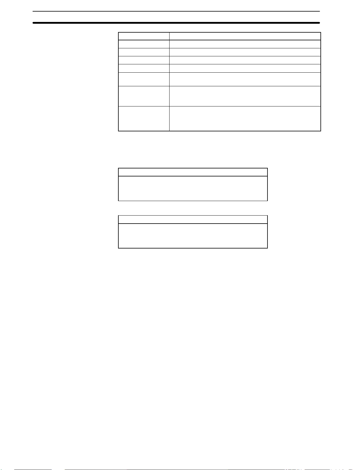
1-1-2 Functions
1-1SectionAbout the Controller Link Support Software
The functions of the Controller Link Support Software are outlined in the following table.
Function Explanation
Data link management Creates and edits data link tables for manually set data
Network parameter
setting
Routing table
management
Communications testing Checks whether the Controller Link Network is working
Status display Displays the network and node status, data link status,
Maintenance Backs up the contents of the EEPROM in the Controller
Connection information
reading
PC ID editing Assigns a unique ID to each PC. Using PC IDs allows
System setup Sets the communications parameters for the Controller
links, registers data link tables at nodes, saves data link
tables as files, and performs other processing related to
data links.
Adjusts network communications parameter settings to
provide the most suitable Controller Link
communications for the user application.
Creates and edits routing tables, registers routing tables
at nodes, and saves routing tables as files. Routing
tables are used to specify data communications paths
when data is transferred to/from remote FA networks.
(See note.)
properly.
error logs, and so on.
Link Unit or Controller Link Support Board as a file and
restores the file to the EEPROM.
Reads node configurations and the status of networks.
(Only available for Optical Ring Networks.)
easier PC management than using network and node
addresses.
Link Support Software, the PC to be connected, the
service conditions for the Controller Link Support
Software, and so on. These must be set before the
Controller Link Support Software is connected to a node.
Note Other FA net wo r k s , s u c h a s C o n t r ol l e r Link Networks, SYSMAC NET
1-1-3 Additional Functions
The following functions were added to the Controller Link Support Software for
when upgrading from Ver. 1.1j to Ver. 2.00.
• Optical Ring Controller Link Networks
Connection configuration data for Optical Ring Controller Link Networks can
be read using the Connection Information Menu. In addition, since an Optical
Ring Network can have up to 62 nodes, the maximum number of nodes for
which each menu’s functions can be used has been increased to 62 (from 32
with Ver. 1.10).
• CS1-series PCs
This version of the Controller Link Support Software can be directly connected
to, and used with, CS1-series PCs.
• Saving and Printing of Error Log Files
Error logs read from specified nodes can be saved to files, and this data can be
read from the file and displayed. The error log data saved to files in this way,
can be displayed and edited using a standard text editor, and used in other
applications. It can also be printed out.
Networks, and SYSMAC LINK Networks, can be inter-connected.
3
Page 13
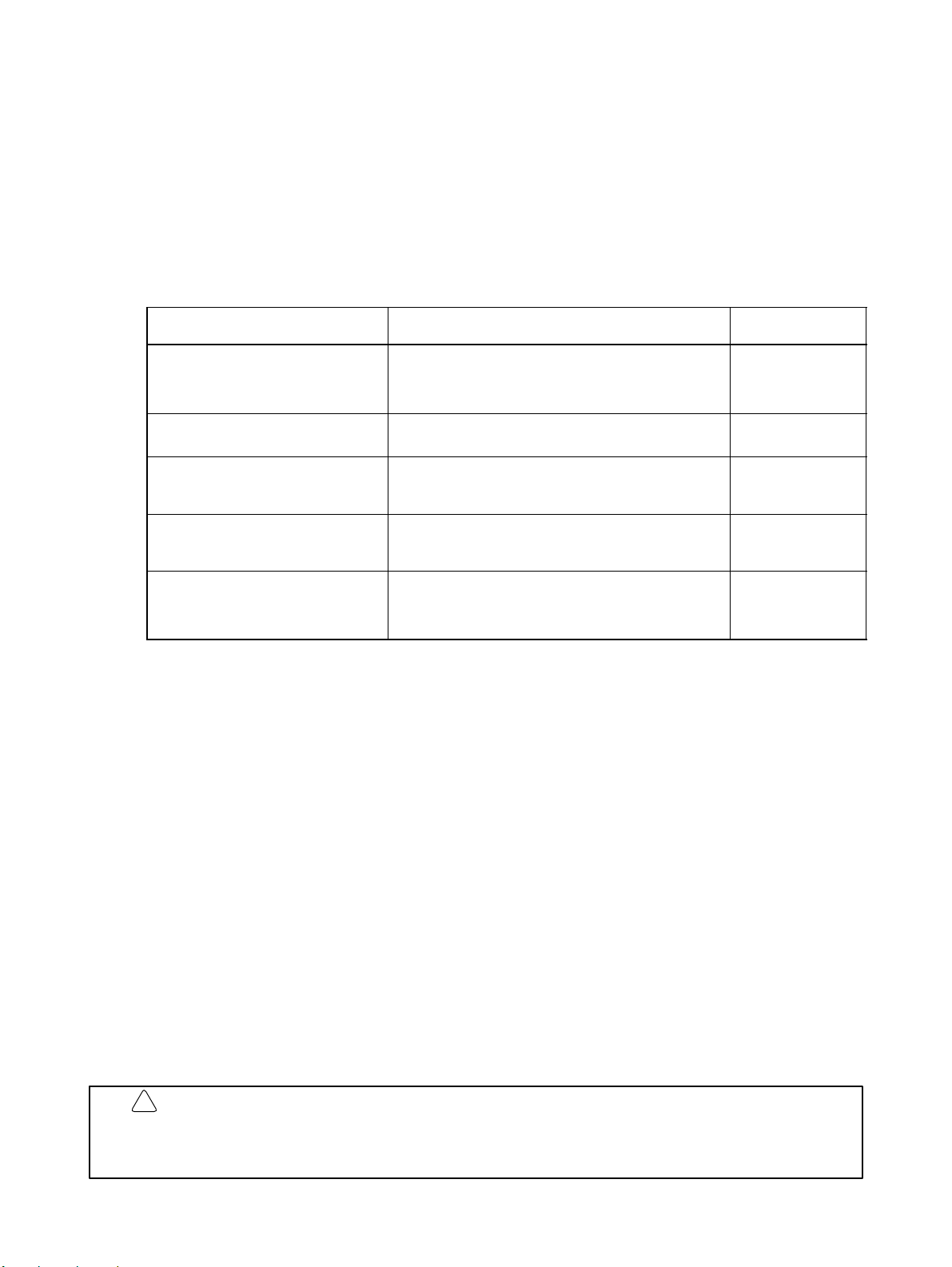
1-1-4 Main Functions
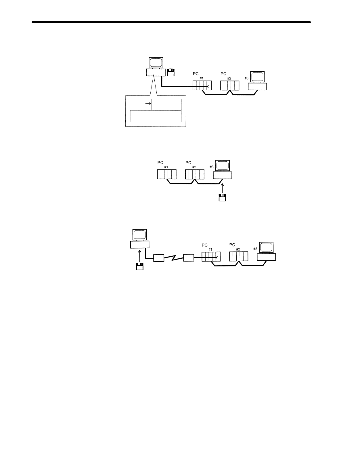
Registering Data Link Tables
Create
Data
link
tables
Controller Link
Support Software
Data link table
for #1 node
(send and
receive areas)
Data link table
for #2 node
(send and
receive areas)
Data link table
for #3 node
(send and
receive areas)
Transfer
Transfer
Transfer
1-1SectionAbout the Controller Link Support Software
IBM PC/AT computer
Controller Link
Network
Data link tables: Tables that specify the send areas at the local node and the numbers
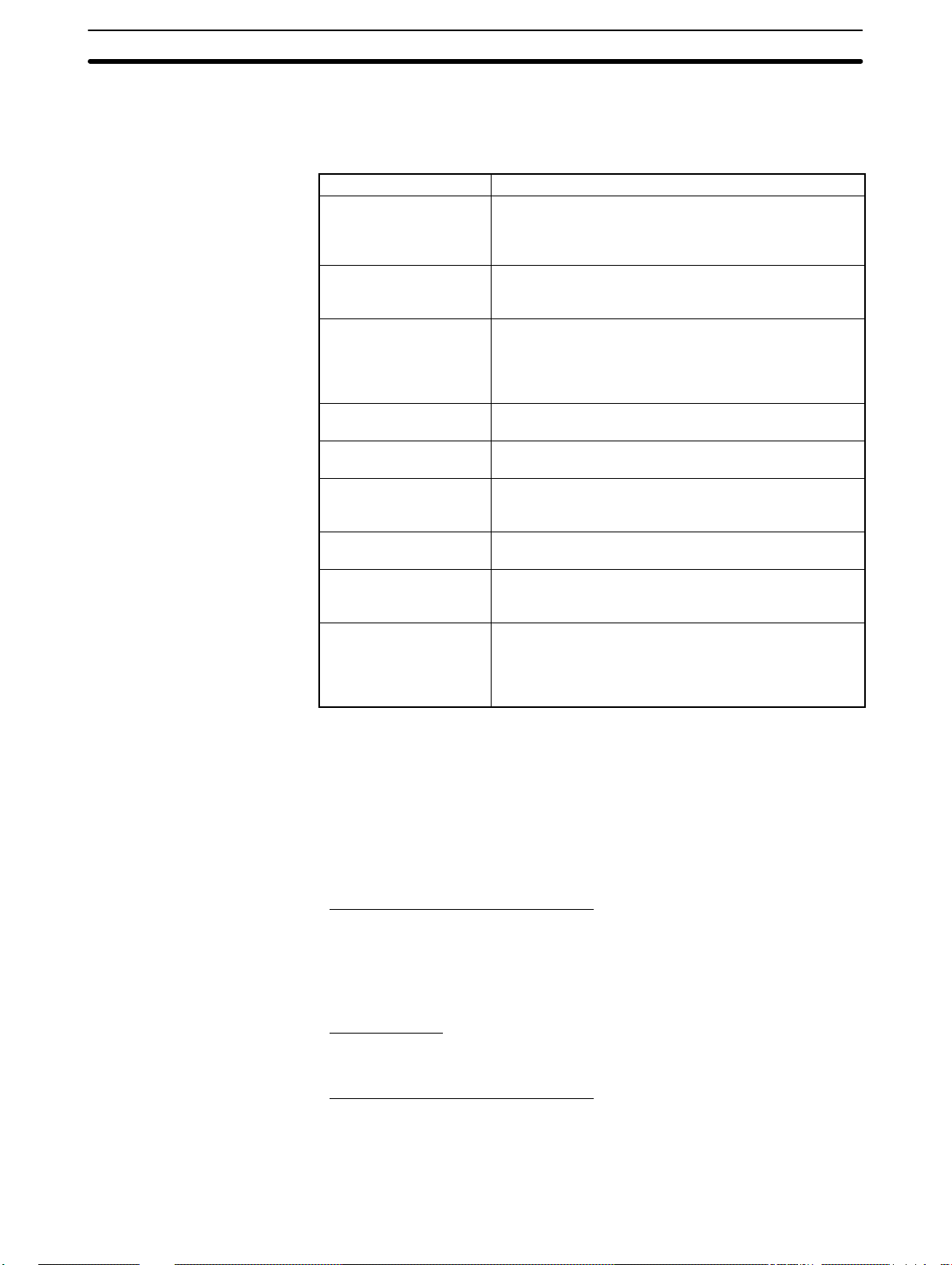
Starting and Stopping Data Links
Displaying Network and Node Status
of words to be received from a particular areas at remote nodes.
Controller Link
Support Software
Starting and stopping
Data link status monitor
Data link area monitor
Network monitor
Node status display
Controller Link
Support Software
Connection
information
IBM PC/AT or compatible
PC (startup node)
Controller Link Network
IBM PC/AT or compatible
Controller Link Network
Controller Link
Support Software
Optical Ring
Controller Link
Network
4
Page 14
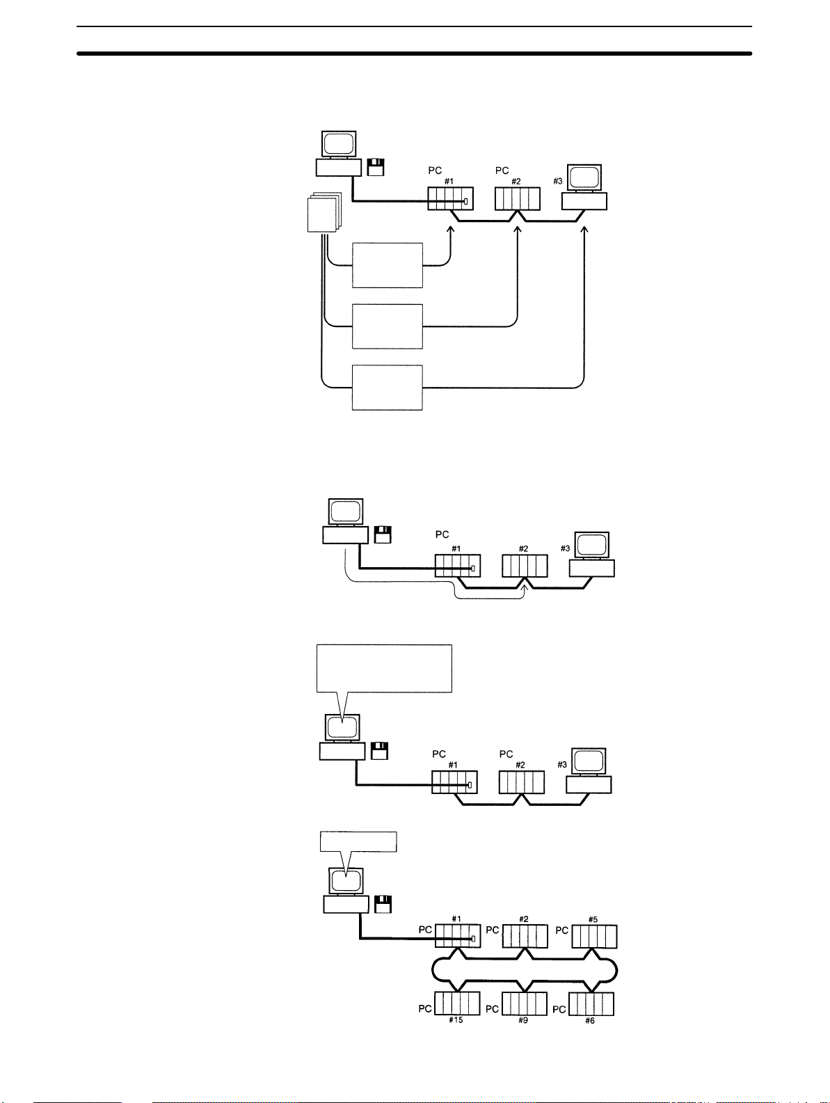
Testing
Controller Link
Support Software
1-1SectionAbout the Controller Link Support Software
IBM PC/AT or compatible
Displaying Error Logs
Echoback test between the local
node and the specified node
Returns the test data unchanged.
Controller Link
Support Software
Test data is broadcasted to all nodes the specified number of times and
the success count is examined (broadcast test.)
Controller Link
Support Software
Controller Link Network
IBM PC/AT or compatible
Controller Link Network
IBM PC/AT or compatible
Node#2Error code
020C
96/09/10 10:00
1-1-5 Connecting to the Network
Connecting to a PC
The Controller Link Support Software can be run from a computer that is connected to a Network PC as a dedicated programming device, i.e., one that is not
a node on the Network.
Controller Link
Support Software
Date Time
IBM PC/AT or
compatible
Controller Link Network
Reading error log
IBM PC/AT or compatible
Controller Link Network
5
Page 15
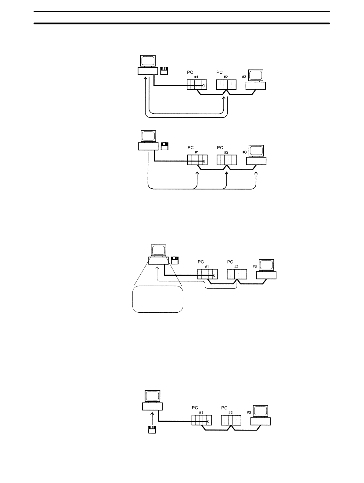
1-1SectionAbout the Controller Link Support Software
The Controller Link Support Software can also be used simultaneously with the
SYSMAC Support Software, i.e., it can be registered in the Option Menu of the
SYSMAC Support Software.
IBM PC/AT or
compatible
Installing in a Computer
Node
The Controller Link Support Software can also be run directly from a Network
computer.
Supplemental Connection Information
The Controller Link Support Software can be connected to PCs via modems.
Option
Menu
SYSMAC Support
Software
Controller Link
Support Software
Controller Link
Support Software
Controller Link Network
IBM PC/AT or compatible
Controller Link Network
IBM PC/AT or compatible
Controller Link
Support Software
Modem
Controller Link
Support Software
IBM PC/AT or compatible
Modem
Controller Link Network
6
Page 16
1-3SectionOperating Environment
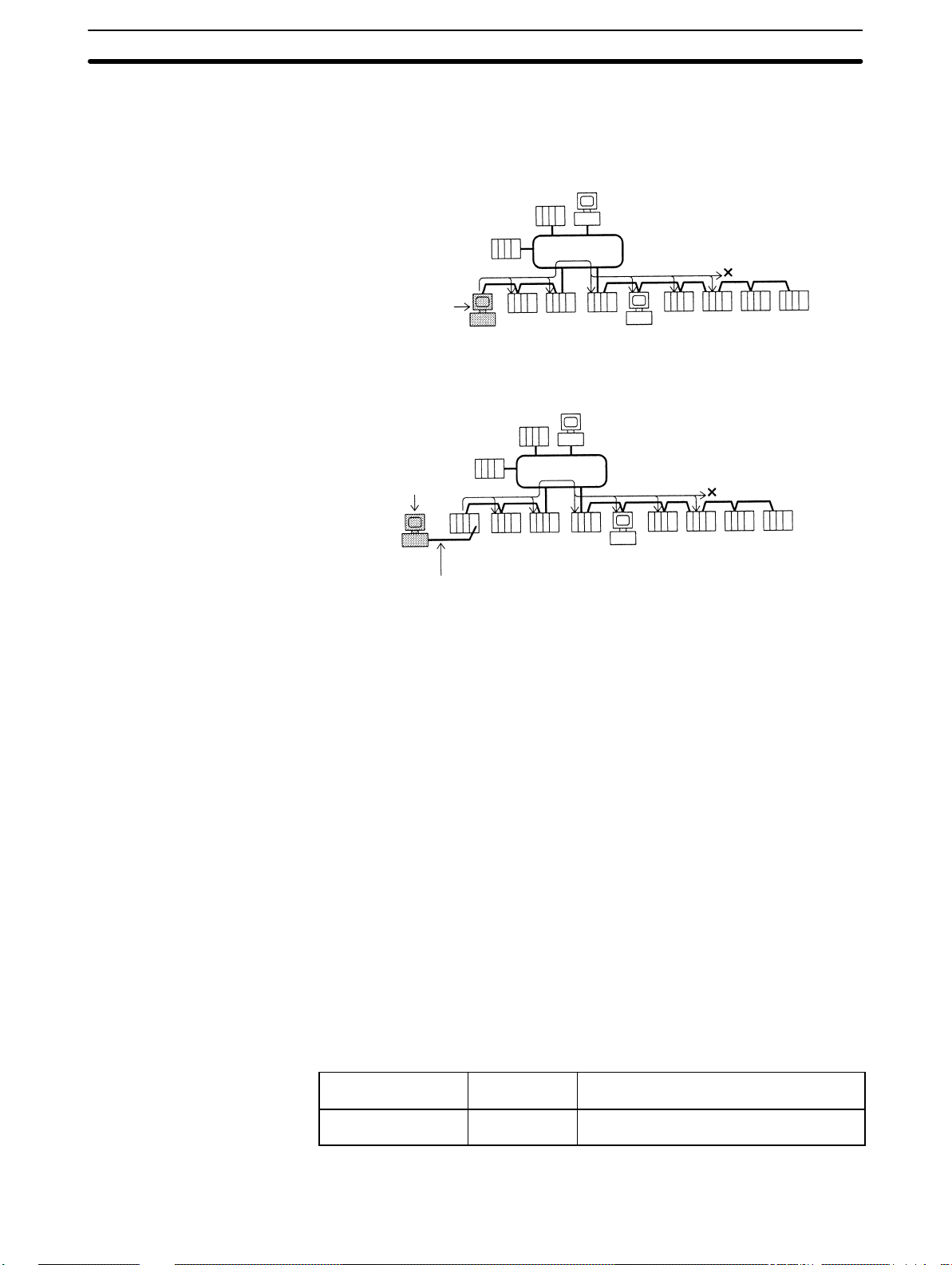
When multiple FA networks are inter-connected, the Controller Link Support
Software can be used to set up and monitor up to three levels of Controller Link
Networks, including the local network. In this case, set routing tables at each
node.
Running from a Computer Node
SYSMAC NET Network (2nd network)
Computer running the
Controller Link Support
Software
Controller Link Network
(1st network: local)
Running from a Programming Device
Controller Link Network (3rd network)
4 Network levels
are not possible
Controller Link Network (4th network)
Computer running the
Controller Link Support
Software
Controller Link Network
(1st network: local)
The connection to the
PC is not counted as
a network level.
SYSMAC NET Network (2nd network)
Controller Link Network (3rd network)
4 Network levels
are not possible
Controller Link Network (4th network)
1-2 Checking Components
When you first open the container, check the contents to be sure you have the
product you ordered and that all items are present.
1-2-1 C200HW-ZW3AT2-E-V2 Controller Link Support Software
The C200HW-ZW3AT2-E-V2 Controller Link Support Software is used when
connecting to a PC from a computer that is not a node on the Network.
• Installation disk (3.5”): 1
• Operation manual (this manual): 1
• User registration card: 1
1-3 Operating Environment
1-3-1 Compatible Computers
The Controller Link Support Software must be run on an IBM PC/A T or compatible computer.
Controller Link
Support Software
C200HW-ZW3AT2-E
-V2
The computer must provide the following.
Manufacturer Model
Various IBM PC/AT or compatible computer
7
Page 17
1-3-2 Printers
1-3SectionOperating Environment
Item Specifications
Processor 80386/80486 or higher
Main memory 450K bytes min.
Floppy disk 3 1/2” 2HD
Hard disk 1M bytes min. empty disk space
Display 640 × 480 dots (i.e., a 640 × 480 dot display with Windows
95/98)
Keyboard The following keys are required: Home, Escape, Control,
Page Up, Page Down, Backspace, F1 through F10, End,
Insert, Delete, Tab.
OS IBM PC-DOS 7.0 or later
Microsoft MS-DOS 6.2 or later
Windows 95/98
To print data from the Controller Link Support Software, use a printer that can
execute the following emulation:
Printer specifications
PCL2 specifications
IBM
ESC/P
The following printers are recommended:
Printers
HP Laser Jet 4P
IBM 4202-003
EPSON MJ-500
8
Page 18
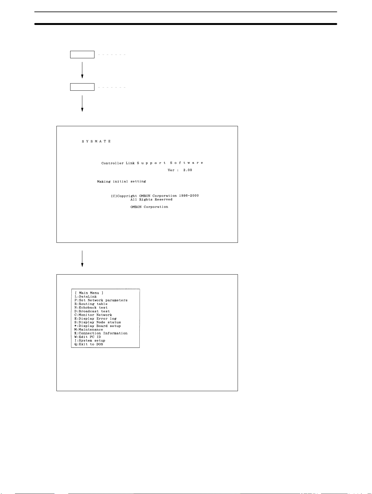
1-4 Overall Flow of Operation
1-4SectionOverall Flow of Operation
Install
Start
Type A:\>INSTALL then press the Enter Key.
Follow the instructions displayed on the screen. The path to
C:\CLK must be specified in AUTOEXEC.BAT.)
Type C:\CLK>CLKSS then press the Enter Key.
This screen is displayed for a
few seconds.
Select the desired item from the
menus to perform setting or
monitoring operations.
9
Page 19
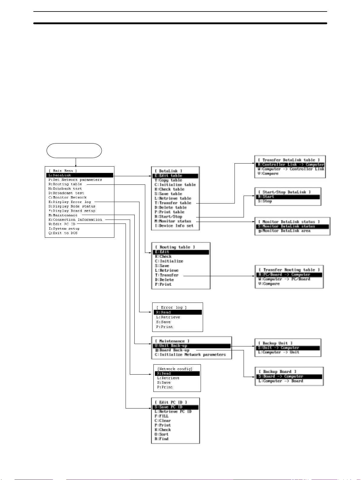
1-5 Menu Hierarchy
This section shows the menu hierarchy of the Controller Link Support Software.
The following illustration shows the overall flow of the menus; it does not show all
the steps necessary to display individual menus.
The menu items marked with asterisks (*) are valid only when a Controller Link
Support Board is installed in the computer. If a Controller Link Support Board i s
not installed in the computer , these menu items cannot be selected.
Note Use Controller LInk Support Software Ver. 1.10 when creating a Controller Link
Network with a Controller Link Support Board. This version is included with the
Support Board. Also, use the SYSMAC C200HW-ZW3AT2-E
3G8F5-CLK11-E/CLK21-E Controller Link Support Software Operation Manual
instead of this manual.
Start Controller Link
Support Software
L
R
1-5SectionMenu Hierarchy
E
*
M
K
W
*
T
R
W
*
T
U
10
B
Page 20

SECTION 2
Installation
This section describes how to install the C200HW-ZW3AT2-E-V2 Controller Link Support Software.
2-1 Preparations for Installation 12. . . . . . . . . . . . . . . . . . . . . . . . . . . . . . . . . . . . . . . . . . . . . . . .
2-1-1 Check Items 12. . . . . . . . . . . . . . . . . . . . . . . . . . . . . . . . . . . . . . . . . . . . . . . . . . . . .
2-1-2 Backing Up the Installation Disk 12. . . . . . . . . . . . . . . . . . . . . . . . . . . . . . . . . . . . .
2-2 Installation Procedure 13. . . . . . . . . . . . . . . . . . . . . . . . . . . . . . . . . . . . . . . . . . . . . . . . . . . . .
11
Page 21

2-1 Preparations for Installation
This section describes the knowledge required and tasks to be performed before installation.
2-1-1 Check Items
Item Contents
Product Installation disk: 1
Operating environment See 1-3 Operating Environment (page 7.)
2-1-2 Backing Up the Installation Disk
Files may be erased or data may be corrupted by operation errors during installation. Create a copy of the floppy disk of the Controller Link Support Software
and use the disk containing the copy for installation. This will protect the master
installation disk should any problem occur. Creation of a disk copy is called backing up the disk.
Prepare one new floppy disk for the backup. After completing the backup, store
the master disk (the original floppy disk) carefully. It will be necessary for future
version upgrades. Use the copied disk for subsequent operation. If the copy is
ever damaged, make a backup copy again. If the master disk is damaged,
please return it to OMRON. OMRON will fix or replace the disk for a small
charge.
This section describes the backup procedure using the following drive structure
as the example. If the drive structure is different, replace the drive name.
Floppy disk drive:Drive A (for 3.5” 2HD floppy disks)
Hard disk drive: Drive C (contains the DOS system)
Note 1) Write protect the Controller Link Support Software disk to ensure that files
are not accidentally erased.
2) Always create a backup copy for the Controller Link Support Software in order to provide protection against data corruption.
3) Use the DISKCOPY command of DOS for backing up the disk. The disk to
which data is to be copied need not be formatted since DISKCOPY command formats the disk before copying.
4) The operating system (MS-DOS) is not provided with the Controller Link
Support Software.
2-1SectionPreparations for Installation
Operation manual (this manual): 1
Required Items
Backup Procedure
12
New floppy disk (3.5” 2HD): 1
1, 2, 3... 1. Turn on the power of the computer. In this example, the computer is started
from the hard disk and command input is prompted as shown below.
C:\>
Note If other applications are running, terminate them and display the DOS
command input prompt. Refer to the related manuals for your computer and application software.
2. Write protect the floppy disk containing the Controller Link Support Board.
3. Enter the following command (underlined section).
C:\>DISKCOPY A: A:
The following messages will be displayed.
Insert SOURCE disk in Drive A:
and press ENTER when ready...
Page 22

4. Insert a disk of the Controller Link Support Software in Drive A.
5. Press the Enter Key. The data on the disk will be read and the following messages will be displayed after a short time.
Insert TARGET disk in drive A:
and press ENTER when ready...
6. Remove the master disk of the Controller Link Support Software from drive
A and insert a new floppy disk.
7. Press the Enter Key. The data will be written to the new disk.
8. If a message prompts replacing the disk, replace the disk in drive A according to the message.
9. When copying is completed, the following message will be displayed.
Create another copy (Y/N)?
10. Press the N key. The following message will be displayed immediately.
Copy another disk (Y/N)?
11. Press the N key.
Note Store the master installation disk carefully.
2-2SectionInstallation Procedure
2-2 Installation Procedure
This section describes how to install the C200HW-ZW3AT2-E-V2 Controller
Link Support Software to the hard disk of a DOS computer connected to a PC.
In this example, the system environment is as follows:
• Floppy disk drive: Drive A
• Destination drive in hard disk: Drive C
• Destination directory: C:\CLK
If the drives to be used are different from those shown in this example, replace
drives A and C in the following descriptions with the actual drives to be used. Any
directory name (up to 8 characters long) can be specified as the destination directory.
Always follow the procedure described in this section. Otherwise, the software
may not be installed properly.
1, 2, 3... 1. Turn on the power to the computer. The computer is started from the hard
disk and command input is prompted as shown below.
C:\>
Note If another applications is started, terminate it and display a DOS com-
mand input prompt. Refer to the related manuals for your computer
and the application software.
2. Insert the Controller Link Support Software disk into drive A.
Note Be sure to use the backup disk previously created when installing the
software.
3. Change the current drive to drive A by entering the following command.
C:\>A:
4. Execute the insta l l a t i o n p rogram by entering the following command. Specify in the underlined section the directory in which the Controller Link Support
Software is to be installed. If a nonexistent directory is specified, it will be
automatically created.
A:\>INSTALL C:\CLK
13
Page 23

2-2SectionInstallation Procedure
When the installation program file is activated, the Controller Link Support
Software files will be copied from the floppy disk to the hard disk. Follow the
instructions displayed on the screen.
Note If the destination directory is omitted, the files will be copied to
C:\CLK.
5. When the installation processing is complete, the following message will be
displayed.
Add ”path=%PATH%;C:\CLK” to AUTOEXEC.BAT.
Command Usage : CLKSS
6. Use a text editor to add the following line anywhere in the AUTOEXEC.BAT
file as indicated by the message in step 5.
path=%PATH%;C:\CLK
This completes the installation procedure.
Note If the Controller Link Support Software is registered in the SYSMAC Support
Software, it can be started from the SYSMAC Support Software’s Option Menu.
See Appendix C Registering the Controller Link Support Software in the SYS-
MAC Support Software (page 163) for the registration procedure. We recommend that the Controller Link Support Software be registered in this way if the
SYSMAC Support Software is already installed.
14
Page 24

SECTION 3
Basic Operations and Connections
This section describes the Controller Link Support Software menu structure and basic operations, such as starting and exiting
the software. It also describes how to connect the computer running the Controller Link Support Software to the Network.
3-1 Starting and Exiting the Controller Link Support Software 16. . . . . . . . . . . . . . . . . . . . . . . .
3-1-1 Starting the Software 16. . . . . . . . . . . . . . . . . . . . . . . . . . . . . . . . . . . . . . . . . . . . . .
3-1-2 Exiting the Software 18. . . . . . . . . . . . . . . . . . . . . . . . . . . . . . . . . . . . . . . . . . . . . . .
3-2 Basic Operations 19. . . . . . . . . . . . . . . . . . . . . . . . . . . . . . . . . . . . . . . . . . . . . . . . . . . . . . . . .
3-2-1 Screen Displays 19. . . . . . . . . . . . . . . . . . . . . . . . . . . . . . . . . . . . . . . . . . . . . . . . . .
3-2-2 Selecting Menu Items 20. . . . . . . . . . . . . . . . . . . . . . . . . . . . . . . . . . . . . . . . . . . . . .
3-2-3 Entering Word Addresses 20. . . . . . . . . . . . . . . . . . . . . . . . . . . . . . . . . . . . . . . . . . .
3-2-4 Selecting a File from the File List Screen 22. . . . . . . . . . . . . . . . . . . . . . . . . . . . . .
3-2-5 Printing Screens 23. . . . . . . . . . . . . . . . . . . . . . . . . . . . . . . . . . . . . . . . . . . . . . . . . .
3-3 Connecting to a Node 23. . . . . . . . . . . . . . . . . . . . . . . . . . . . . . . . . . . . . . . . . . . . . . . . . . . . .
3-3-1 Connection Method 23. . . . . . . . . . . . . . . . . . . . . . . . . . . . . . . . . . . . . . . . . . . . . . .
3-3-2 PC Settings 25. . . . . . . . . . . . . . . . . . . . . . . . . . . . . . . . . . . . . . . . . . . . . . . . . . . . . .
15
Page 25

3-1SectionStarting and Exiting the Controller Link Support Software
3-1 Starting and Exiting the Controller Link Support Software
This section describes how to start and exit the Controller Link Support Software.
Note 1) In the following examples, all command strings are shown in uppercase.
They can also be entered in lowercase.
2) If the Controller Link Support Software is registered in the SYSMAC Support
Software, it can be started from the SYSMAC Support Software’s Option
Menu. See Appendix C Registering the Controller Link Support Software in
the SYSMAC Support Software (page 163) for the registration procedure.
3) The Controller Link Support Software can be run from Windows. See Ap-
pendix D Running the Controller Link Support Software under Windows
95/98 (page 165) for the procedure.
3-1-1 Starting the Software
This section describes how to start the Controller Link Support Software.
In this example, the system environment is as follows:
• Hard disk: Drive C
• Directory for Controller Link Support Software: C:\CLK
If the drive and directory to be used are different from those shown in this example, replace drive C and directory C:\CLK in the following descriptions with the
actual drive and directory being used.
Basic Procedure
1, 2, 3... Turn on the power of the computer. The computer will be started from the
hard disk and command input will be prompted as shown below.
C:\>
Note If another application is started, terminate it and display a DOS com-
mand input prompt. Refer to the related manuals for your computer
and the application software.
Make sure that the current drive is the drive in which the Controller Link Support Software has been installed.
Note a) The current drive is the default drive that files are read from or writ-
ten to. If a file name is specified without a drive name, the file will
be searched or written in the current drive.
b) When C:\> is displayed as shown in step , drive C is the current
drive.
If the current drive is not the drive in which the Controller Link Support Software has been installed, enter the drive name as below to change the current drive.
Example: When changing the current drive from drive A to drive C
A:\>C:
Enter the command shown below to change the current directory to the directory in which the Controller Link Support Software has been installed.
Specify in the underlined section the directory in which the Controller Link
Support Software has been installed.
Example: Controller Link Support Software is in directory CLK
C:\>CD \CLK
16
Note a) The current directory is the default directory that files are read
from or written to. If a file is specified without a directory name, the
file will be searched or written in the current directory.
Page 26
Startup Options
3-1SectionStarting and Exiting the Controller Link Support Software
b) If the path to the Controller Link Support Software directory is spe-
cified in the AUTOEXEC.BAT file, this step need not be performed.
Enter the following command string to start the Controller Link Support Software.
C:\CLK>CLKSS
Note a) Options can be specified in the start command. See Start Options
(on page 17) for details.
b) If the Controller Link Support Software is started normally, the
logo screen and the Main Menu will be displayed in order. The version number of the Controller Link Support Software appears on
the logo screen.
The operation mode can be specified using options when starting the Controller
Link Support Software. The option entry format is as follows:
CLKSS /B [/OSSS path]
/U
Portions in brackets [ ] may
be omitted. The brackets
themselves are not input.
Option Meaning
/B The Controller Link Support Software is started for use with a
/U The Controller Link Support Software is started for use with a
Both /B and
/U omitted
/OSSS path The Controller Link Support Software is started with the same
Controller Link Support Board (as a node.) This option is valid
only when a Controller Link Support Board is installed in the
computer. If a Controller Link Support Board is not installed or
does not operate normally, an error message will be displayed.
Controller Link Unit (for connecting to a PC.) Even if the
Controller Link Unit is not connected to a PC, no error will occur.
The Controller Link Unit may be connected to PC only when
data needs to be transferred between them.
The Controller Link Support Software is started in either of the
following modes, depending on the presence or absence of the
driver for the Controller Link Support Board.
When the driver exists: The Controller Link Support Software is
started for use with the Controller Link Support Board (as a
node.)
When the driver does not exist: The Controller Link Support
Software is started for use with the Controller Link Unit (for
connecting to a PC.)
conditions as the SYSMAC Support Software by reading the
information specified in the System Setup of the SYSMAC
Support Software.
In the SSS path, specify the directory in which the SYSMAC
Support Software is installed (e.g., C:\SYSMATE.) The following
system setup information is read.
Communications parameters
Printer model
Data drive
This option is invalid when the SYSMAC Support Software is not
installed or does not operate normally.
17
Page 27
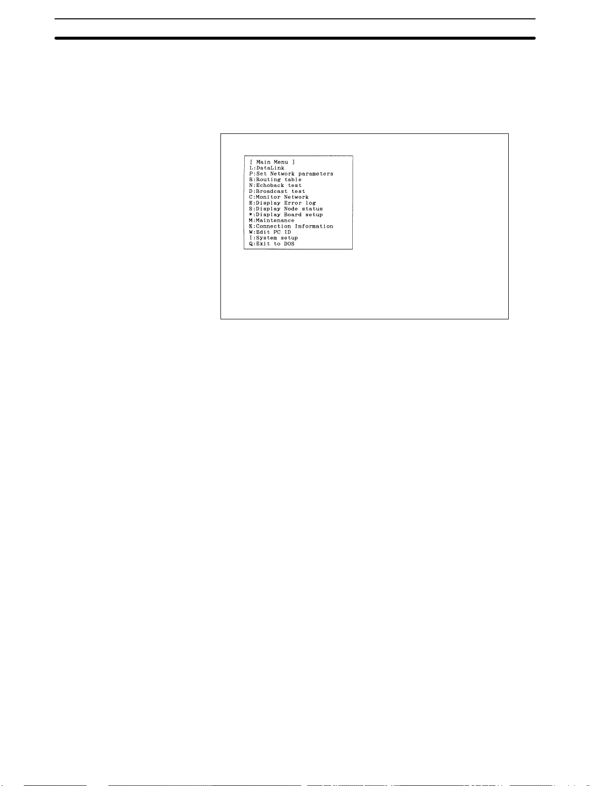
3-1-2 Exiting the Software
1, 2, 3... Press the F1 (Menu) Key to display the Main Menu.
If the Main Menu does not appear when the F1 Key is pressed, press the
Escape Key or F10 (End) Key to terminate the active function, and then
press the F1 Key.
3-1SectionStarting and Exiting the Controller Link Support Software
Select “Q: Exit to DOS” from the Main Menu.
T o select “Q: Exit to DOS,” press “Q,” or use the Up and Down Cursor Keys
to highlight “Q: Exit to DOS” and then press the Enter Key.
The Controller Link Support Software will terminate and the system will be
ready to receive the next command as shown below.
C:\>
Note a) If the Controller Link Support Software is started from the SYS-
MAC Support Software or Windows, it will return to the original
state when terminated.
b) If the Controller Link Support Software is started for use with the
Controller Link Support Board, the Controller Link Support Board
will be disconnected from the network when the software terminates. Then, an error indicating that the number of nodes participating in the network has decreased (error code 0206 Hex) will be
recorded in the error log in the other nodes connected to the network.
18
Page 28
3-2 Basic Operations
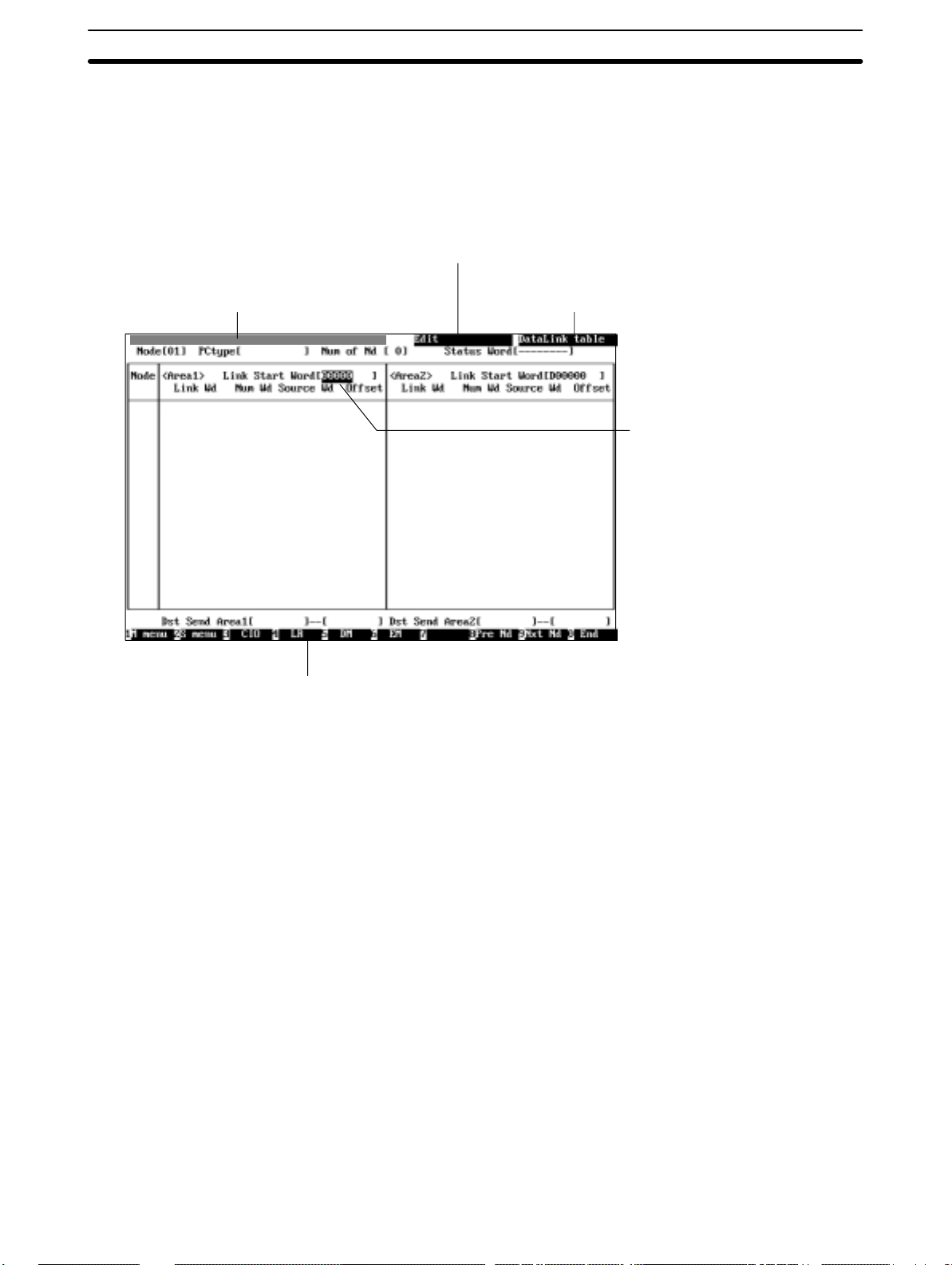
3-2-1 Screen Displays
A sample screen for the Controller Link Support Software is shown below.
Error message display area
An error message is displayed if an error occurs
during Controller Link Support Software operation.
3-2SectionBasic Operations
Subfunction name
The submenu item corresponding to the current
function is displayed. Nothing is displayed when the
current function (main menu item) has no submenu.
Function name
The main menu item corresponding
to the current function is displayed.
Cursor
The cursor indicates the
selection or input object. On the
menu, move the cursor to a
desired item, then press the
Enter Key. For setting, enter a
character string or numerical
value at the cursor position.
Function Keys
The Function Keys labels are arranged from left to right and correspond to the F1 to
F10 Keys, respectively. Pressing a Function Key executes the displayed function.
For example, pressing the F1 (Menu) Key displays the Main Menu. The functions of
Function Keys differ according to the screen displayed.
Note The display color of the function and subfunction name fields indicates the de-
vice to which the Controller Link Support Software is connected.
Blue: The Controller Link Support Software is running for connecting to a
Controller Link Unit (for connecting to a PC.)
Yellow: The Controller Link Support Software is running for use with the
Controller Link Support Board (as a node.)
The destination to which the Controller Link Support Software is to be connected
can be selected by specifying an option when starting the software (see page
17.)
19
Page 29
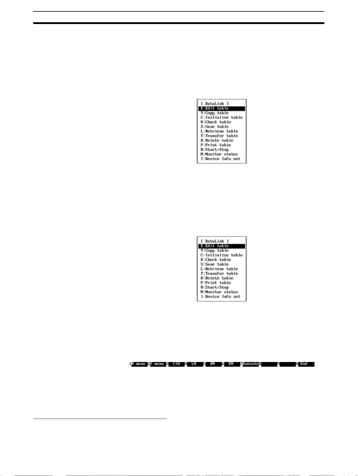
3-2-2 Selecting Menu Items
Menu items can be selected in either of the following two ways.
3-2SectionBasic Operations
Using Shortcut Keys
Using the Cursor
As shown in the figure below, a letter is displayed on the left of each main menu
item or submenu item. This key for this letter on the keyboard is called a shortcut
key. You can select a menu item by simply pressing the corresponding shortcut
key.
Example: Data Link Submenu
In this example, pressing “K” at the Data Link Submenu selects “K: Check
table.”
Part of each Controller Link Support Software menu is always highlighted. This
highlighted portion is called the cursor. The cursor indicates a selected object.
To move the cursor, use the Up and Down Cursor Keys.
Press the Enter Key to select the item at the cursor position.
Example: Data Link Submenu
In this example, pressing the Enter Key selects “E:Edit table.”
3-2-3 Entering Word Addresses
The Controller Link Support Software displays the Function Keys at the bottom
of the screen as shown below when the cursor moves to the word address entry
field.
The word address entry methods for CIO (IR), LR, and DM Areas are slightly
different from that for the EM Area.
Note When entering data in the first status word field, you can also use the “–” Key
and the Delete Key to set the first status word to its default value.
Specifying CIO, LR, and DM Addresses
1, 2, 3... Specify the data area by pressing the corresponding Function Key.
In the following example, the DM Area is specified by pressing the F5 (DM)
Key.
20
Page 30

3-2SectionBasic Operations
Example:
[D00000 ]
Specify a word address by pressing the numeric keys.
Each time a numeric key is pressed, the corresponding number appears on
the right end of the highlighted portion and the other digits shift to the left.
Example: When pressing “1”, “2”, and “5” in this order
[D00001 ] [D00012 ] [D00125 ]→→
Press the Enter Key to register the entered data.
The entered data will be automatically checked according to the node model
specified as described in 5-3-15 Specifying Node Models (page 81.)
Example:
[D00125 ]
Note You cannot use the Backspace Key or the Delete Key when entering a word ad-
dress. If an incorrect digit is entered, continue to enter digits until the correct fivedigit number is entered. Each time a digit is entered, the incorrect digit shifts to
the left and eventually disappears from the field.
The Function Keys for data area selection (F3 to F6) are valid while a word address is being entered. If an incorrect digit is entered, the word address entry
procedure can be canceled and restarted by pressing one of the F3 to F6 Keys.
Specifying EM Addresses
1, 2, 3... Press the F6 (EM) Key.
Note 1) You cannot use the Backspace Key or the Delete Key when entering a word
The display will wait for input of the bank.
Example:
[E0_00000 ]
Enter a bank number by pressing one of the numeric keys or A” to “F.”
The bank number must be a single-digit hexadecimal number. The bank
number must be followed by a word address.
Example: Pressing “1” (bank number 1)
[E1_00000 ]
Specify a word address by pressing the numeric keys.
Each time a numeric key is pressed, the corresponding number appears on
the right end of the highlighted portion and the other digits shift to the left.
Example: When pressing “4”, “1”, and “9” in this order
[E1_00004] [E1_00041 ] [E1_00419 ]→→
Press the Enter Key to register the entered data.
The entered data will be automatically checked according to the node model
specified as described in 5-3-15 Specifying Node Models (page 81.)
Example:
[E1_00419 ]
address. If an incorrect digit is entered, continue to enter digits until the correct five-digit number is entered. Each time a digit is entered, the incorrect
digit shifts to the left and eventually disappears from the field.
The Function Keys for area selection (F3 to F6) are valid while a word address is being entered. If an incorrect digit is entered, the word address entry
procedure can be canceled and restarted by pressing one of the F3 to F6
Keys.
2) If an incorrect bank number is entered, it cannot be corrected. Press the F6
(EM) Key to restart the entry procedure.
21
Page 31

3-2-4 Selecting a File from the File List Screen
The Controller Link Support Software allows you to display a list of files in a directory and select one of the files. This will save you the trouble of entering file
names and also prevent entry mistakes.
Displaying a File List
The F8 Key serves as the “Files” Function Key as shown below and allows you
to select a file from the file list. File lists can be displayed in any window where the
F8 Key has “Files” displayed for it.
Selecting from a File List
1, 2, 3... Specify in the file name entry field the directory for which the file list is to be
displayed. Enter a file name with Alphanumeric Keys, the Insert Ke y, the D elete Key, and the Backspace Key.
The character string before the last backslash (\) is treated as a directory
name. When the window is first displayed, the directory specified in “Data
disk drive” of the “System setup” Menu is displayed.
Example:
3-2SectionBasic Operations
In this example, C:\CLK\DATA is treated as the directory name.
Press the F8 (Files) Key.
A list of files in the specified directory will be displayed.
Example:
Select a file.
Use the Cursor Keys to move the cursor to a desired file, then press the Enter Key. Subdirectories are displayed as <DIR> in the “Size” column. Selecting a subdirectory displays a list of files in the subdirectory.
Selecting a file will return you to the original screen. The specified file name
will appear in the file name entry field.
Example: Selecting LINE3.CLK
22
Page 32

Note In the file list screen, you can switch to the file list of a subdirectory but cannot
return to the parent directory. Press the Escape Key to return to the file name
entry screen, then specify the directory again.
3-2-5 Printing Screens
The Controller Link Support Software allows you to print the screen from the
connected printer.
1, 2, 3... Make sure that the correct printer model is specified in “Printer model” of the
3-3SectionConnecting to a Node
If necessary, you can press the F8 (Files) Key and select a file again from the
file list.
Press the Enter Key.
The file will be selected.
“System setup” Menu.
Make sure that the printer is connected to the computer in which the Control-
ler Link Support Software is running and that the printer is ready to operate.
Press the Print Screen Key.
The current screen images will be printed.
Note The Controller Link Support Software cannot be operated while printing.
3-3 Connecting to a Node
3-3-1 Connection Method
Running from a Computer Node
If the Controller Link Support Software is being used in a computer in which a
Controller Link Support Board is installed and the computer is connected as a
Network node, you need not bother to connect the Controller Link Support Software.
If the Support Board is activated normally , the Controller Link Support Software
will be automatically connected to nodes when started.
Connecting to a PC
If the computer in which the Controller Link Support Software is installed is to be
connected to a PC, use the SYSMAC Support Software connection cable to connect the computer to the PC.
Note The Controller Link Support Software communicates with a PC only when data
is transferred between them. Therefore, you may connect the computer to a PC
only when necessary to transfer data or monitor status.
Peripheral Port on CS1-series PCs
Computer Cable PC PC
PC/AT CS1W-CN226/626 (D-Sub 9-pin ↔ dedicated connector)
RS-232C Peripheral port
Peripheral port on
CS1-series PC
communications
Peripheral Bus or
Host Link
23
Page 33

Peripheral Port on C200HX/HG/HE PCs
3-3SectionConnecting to a Node
Computer Cable PC PC
PC/AT CQM1-CIF02 (D-Sub 9-pin ↔ dedicated connector)
RS-232C Peripheral port
Peripheral port on
C200HX/HG/HE
PC
communications
Peripheral Bus or
Host Link
Peripheral Port on CVM1 and CV-series PCs
Computer Cable PC PC com-
PC/AT
If the RS-232C
connector on the
computer is a 9-pin
connector, use a
commercially available
9-to-25-pin conversion
adapter to connect the
cable to the computer.
CV500-CIF01 (D-Sub 25-pin ↔ dedicated connector) Peripheral
Peripheral device bus connectorRS-232C
device
connector
on CVM1 or
CV-series
PC
munica-
tions
Peripheral
Bus
Peripheral Port on CQM1H PCs
Computer Cable PC PC com-
PC/AT
CQM1-CIF02 and CS1W-CN114
RS-232C Host Link Port on PC’s CPU Unit
Computer Cable PC PC com-
PC/AT
If the RS-232C
connector on the
computer is a 9-pin
connector, use a
commercially available
9-to-25-pin conversion
adapter to connect the
cable to the computer.
XW2Z-200S (D-Sub 25-pin ↔ D-Sub 9-pin)
XW2Z-500S (D-Sub 25-pin ↔ D-Sub 9-pin)
munica-
tions
Peripheral
port on
CQM1H PC
RS-232C
port on
CS1-series
PC
RS-232C
RS-232C portRS-232C
port on
C200HX/H
G/HE (see
note),
CVM1,
CV-series,
or CQM1H
PC
Peripheral
Bus or Host
Link
munica-
tions
Peripheral
Bus or Host
Link
Host Link
24
Note Connection is only possible to a C200HX/HG/HE CPU Unit with an
RS-232C port.
Page 34

RS-232C Port on Host Link Unit
Computer Cable PC (Host
PC/AT
CV500-LK201 port 1, in full-duplex mode:
XW2Z-200S (D-Sub 25-pin ↔ D-Sub 9-pin)
XW2Z-500S (D-Sub 25-pin ↔ D-Sub 9-pin)
CV500-LK201 port 2, in full-duplex mode:
XW2Z-200P (D-Sub 25-pin ↔ D-Sub 25-pin)
XW2Z-500P (D-Sub 25-pin ↔ D-Sub 25-pin)
Select an appropriate cable according to the shape of the RS-232C connector
on the Host Link Unit.
RS-232C Port on Serial Communications Board/Unit
Computer Cable PC(Serial
PC/AT
XW2Z-200S (D-Sub 25-pin ↔ D-Sub 9-pin)
XW2Z-500S (D-Sub 25-pin ↔ D-Sub 9-pin)
3-3SectionConnecting to a Node
Link Unit)
RS-232C
port on
Host LInk
Unit for
CVM1 or
CV-series
PC
(CV500-LK
201)
RS-232C portRS-232C
Communic
ations
Board/Unit)
RS-232C
port on
Serial Communications
Board
(CS1W-SC
B21/41) or
RS-232C portRS-232C
Serial Communications
Unit
(CS1W-SC
U21) for
CS1-series
PC
PC com-
munica-
tions
Host Link
PC com-
munica-
tions
Host Link
3-3-2 PC Settings
Peripheral Bus
CS1-series PCs
If the Controller Link Support Software is to communicate with a PC via the peripheral bus, the PC must be set to the same baud rate as the Controller Link
Support Software.
Note See 5-14-3 Setting PC Communications (on page 137) in 5-14 System Setup to
set the baud rate for the Controller Link Support Software.
Connecting to Peripheral Port
When connecting to the peripheral port on the CPU Unit, set DIP switch pin 4 to
OFF, and set the baud rate for the Controller Link Support Software to the maximum value (19,200 bps). Alternatively, set DIP switch pin 4 to ON and make the
PC Setup settings for the CPU Unit using CX-Programmer. Select the peripheral
port and set the serial communications mode to peripheral bus, and make the
same communications settings as the Controller Link Support Software.
Connecting to RS-232C Port
When connecting to the RS-232C port on the CPU Unit, set DIP switch pin 5 to
ON, and set the baud rate for the Controller Link Support Software to the maximum value (19,200 bps). Alternatively, set DIP switch pin 5 to OFF and make the
PC Setup settings for the CPU Unit using CX-Programmer. Select the RS-232C
port and set the serial communications mode to peripheral bus, and make the
same communications settings as the Controller Link Support Software.
25
Page 35

3-3SectionConnecting to a Node
C200HX/HG/HE PCs
Set the same baud rate as the Controller Link Support Software in PC Setup
words DM 6650 and DM 6651 of the CPU Unit.
Setting the Standard Communications Parameters
Peripheral port: DM 6650
Communications parameters
0: Standard communications parameters (9600 bps)
1: According to DM6651
Initial status: 0000 (Standard communications parameters at 9,600 bps.)
Setting the Baud Rate
Peripheral port: DM 6651 bits 0 to 7
Baud rate
00: 1200 bps (see note)
01: 2400 bps
02: 4800 bps
03: 9600 bps
04: 19200 bps
Initial status: 0000 (1200 bps)
Note The baud rate cannot be set to 1,200 bps for the Controller Link Support Soft-
ware.
26
Page 36

3-3SectionConnecting to a Node
CVM1 and CV-series PCs
DIP switch
CQM1H PCs
Use DIP switch pins 1 and 2 on the CPU Unit to set the same baud rate as the
Controller Link Support Software.
DIP switch pins
1 2
OFF OFF 50 Kbps (see note)
ON OFF 19,200 bps
OFF ON 9,600 bps
ON ON 4,800 bps
Baud rate
Note The baud rate cannot be set to 50 kbps for the Controller Link Support
Software.
Connecting to Peripheral Port
Use one of the following methods when connecting to the peripheral port on the
CPU Unit.
a) Set DIP switch pins 5 and 7 to ON, and set the baud rate for the Controller
Link Support Software to 9,600 bps.
b) Set DIP switch pin 5 to OFF and pin 7 to ON, and set the PC Setup word
DM 6650 (peripheral port settings) to 0000 Hex (standard setting). Set
the baud rate for the Controller Link Support Software to 9,600 bps.
c) Set DIP switch pin 5 to OFF and pin 7 to ON, and set the PC Setup word
DM 6650 (peripheral port settings) to 0001 Hex (settings according to
DM 6651). Set the communications settings (DM 6651: peripheral port
settings) to the same settings as the Controller Link Support Software.
Set the baud rate for the Controller Link Support Software to a value in
the range 2,400 to 19,200 bps.
Connecting to RS-232C Port
Peripheral bus connection to the RS-232C port is not possible.
Host Link
CS1-series PCs
If the Controller Link Support Software is to communicate with a PC via a Host
Link, the PC must be set to the same communications parameters as the Controller Link Support Software.
Note See 5-14-3 Setting PC Communications (on page 137) in 5-14 System Setup to
set the communications parameters for the Controller Link Support Software.
Connecting to Peripheral Port
When connecting to the peripheral port on the CPU Unit, set DIP switch pin 5 to
ON and make the PC Setup settings for the CPU Unit using CX-Programmer.
Select the peripheral port and set the serial communications mode to Host Link,
and make the same communications settings as the Controller Link Support
Software.
Connecting to RS-232C Port
When connecting to the RS-232C port on the CPU Unit, set DIP switch pin 5 to
OFF and make the PC Setup settings for the CPU Unit using CX-Programmer.
27
Page 37

3-3SectionConnecting to a Node
Select the RS-232C port and set the serial communications mode to Host Link,
and make the same communications settings as the Controller Link Support
Software.
CS1-series Serial
Communications
Board/Unit
In the software switch settings of the Serial Communications Board/Unit registered in the CX-Programmer’s I/O table, select the serial port for connection, set
the serial communications mode to Host Link, and make the same communications settings as the Controller Link Support Software.
28
Page 38

3-3SectionConnecting to a Node
C200HX/HG/HE PCs
Use the PC Setup (DM Area) of the PC to set the communications parameters
for the port to be used (peripheral port or RS-232C port.)
Note When DIP switch pin 5 on the CPU Unit is set to ON, the communications param-
eters are set as follows, regardless of the PC Setup:
Communications: Host Link mode
Node No.: 00
Start bits: 1 bit
Data bits: 7 bits
Stop bits: 2 bits
Parity: Even
Baud rate: 9,600 bps
Transmission delay: None
Setting Standard Communications Parameters
RS-232C port: DM6645
Communications mode
Set to (0: Host Link)
Not related when Host Link is set
CTS control (Yes/No)
Communications parameters
0: Standard communications parameters
1: According to DM 6646
Initial status: 0000 (Standard communications at 9,600 bps.)
Bits 8 to 11 are valid for only the master node with 1:1 link.
Bits 0 t o 7 and 12 to 15 are valid only when DIP switch pin 5 on the CPU Unit is set
to OFF.
The standard communications parameters are as follows:
Start bits: 1 bit
Data bits: 7 bits
Stop bits: 2 bits
Parity: Even
Baud rate: 9,600 bps
Always set the mode to be used.
If the above communications parameters are acceptable, specify 00 in the lower
two digits.
Setting Communications Parameters
The Controller Link Support Software can communicate with PC only when DIP
switch pin 5 on the CPU Unit is set to OFF and DM 6645 is set to use DM 6646
settings.
RS-232C port: DM 6646
Transmission frame format (see table)
Baud rate (see table)
Initial status: 0000 (Start bits: 1, Data length: 7, Stop bits: 1, Even parity, 1,200 bps.)
29
Page 39

Transmission Frame Format
3-3SectionConnecting to a Node
Setting Start
bits
00 1 7 1 Even 06 1 8 1 Even
01 1 7 1 Odd 07 1 8 1 Odd
02 1 7 1 None 08 1 8 1 None
03 1 7 2 Even 09 1 8 2 Even
04 1 7 2 Odd 10 1 8 2 Odd
05 1 7 2 None 11 1 8 2 None
Data
length
Stop
bits
Parity Setting Start
bits
Data
length
Stop
bits
Parity
Baud Rate
Setting Baud rate
00 1,200 bps
01 2,400 bps
02 4,800 bps
03 9,600 bps
04 19,200 bps
The baud rate cannot be set to 1,200 bps for the Controller Link Support Software.
Set the communications parameters for the PC according to the communications parameters for the Controller Link Support Software.
Setting the Node Number
CVM1 and CV-series PCs
Communications
port
RS-232C
RS-422
RS-232C port: DM 6648
Node no. (2 digit BCD) 00 to 31
Initial status: 00 (node no. 00.)
When multiple PCs are connected to the host computer, a node number is assigned to each PC for identification purposes. Assign the PC the same node
number as that specified in the Controller Link Support Software.
Use the DIP switch on the PC and the PC Setup to set the communications parameters for the Host Link connection.
Note Use the SYSMAC Support Software to set up the PC Setup.
I/O port setting (selector switch)
Set the selector switch to RS-232C.
System setup (DIP switch pin 4)
To set to the values specified by the DIP switch: Set DIP switch pin 4 to ON.
To set to the values specified in the PC Setup: Set DIP switch pin 4 to OFF.
Note For CPU Units manufactured before June 1995 (lot No.
jj65), the default values specified by the DIP switch differ
from those specified in PC Setup as follows:
The default values specified by the DIP switch are 2,400 bps,
one stop bit, even parity, and 7-bit data length.
The default values specified in the PC Setup are 9,600 bps, two
stop bits, even parity, and 7-bit data length.
For CPU Units manufactured after July 1995 (lot No. jj75), the
values specified in the DIP switch have been changed to 9,600 bps
and two stop bits to make them identical with those of the PC
Setup.
30
Page 40

3-3SectionConnecting to a Node
CVM1/CV-series Host
Link Unit
Set the communications parameters for the port to be used (port 1 or 2) with the
rotary switches, DIP switch, and CPU Bus Unit System Setup of the CVM1/CV series Host Link Unit (CV500-LK201).
Setting the Node Number for Communications Port 2
When multiple PCs are connected to the host computer, a node number is assigned to each PC for identification purposes. Decimal numbers 0 to 31 can be
assigned as the node number of communications port 2. Set the tens digit with
the left switch and the ones digit with the right switch.
Setting Example
Node No.
x 10
1
0
Node No.29x 10
Note 1) Do not specify a node number higher than 31. Doing so results in a error and
lights the ERC2 indicator on the display panel.
2) Since the Controller Link Support Software and the Host Link Unit are always connected on the one-to-one basis, the node number can normally be
0.
3) The node number of communications port 1 is fixed at 0.
DIP Switch Settings of CVM1/CV-series Host Link Units
Communications port 1
(RS-232C)
Communications port 2
(RS-232C/RS-422A)
Communications port switch
(RS-232C/RS-422A)
DIP switch
31
Page 41

For each DIP switch pin, ON is on the left side and OFF is on the right side.
No. Function Setting Meaning
1 Communications
parameter settings (for
communications ports 1
and 2) (see note)
2 CTS switch
(communications port 1)
3 CTS switch
(communications port 2)
4 Reserved for system use
5 Loopback test
6 Test port selection
ON The communications parameters
for communications ports 1 and 2
are as follows:
Baud rate: 9,600 bps
Stop bits: 2 bits
Parity: Even
Data bits: 7 bits
Xon/Xoff control: No
Communications method: Full
duplex
OFF The values specified for the CPU
Bus Unit System in the PC are
used as communications
parameters. The initial values are
as follows:
Baud rate: 9,600 bps
Stop bits: 2 bits
Parity: Even
Data bits: 7 bits
Xon/Xoff control: Not
Communications method: Full
duplex
ON The CTS signal (ready to receive)
is always set to ON (0 V fixed.)
Always set this switch pin to ON
when connecting the Controller
Link Support Software.
OFF Cannot be set.
ON The CTS signal (ready to receive)
is always set to ON (0 V fixed.)
Always set this switch pin to ON
when connecting the Controller
Link Support Software.
OFF Cannot be set.
ON Cannot be set.
OFF Always set this bit to OFF.
ON Cannot be set when the
Controller Link Support Software
is connected.
OFF Always set this switch pin to OFF
when connecting the Controller
Link Support Software.
ON Cannot be set when the
Controller Link Support Software
is connected.
OFF Always set this switch pin to OFF
when connecting the Controller
Link Support Software.
3-3SectionConnecting to a Node
32
Page 42

3-3SectionConnecting to a Node
Note For Host Link Units manufactured after July 1995 (lot No.**75), the communica-
tions parameter settings when DIP switch pin 1 is ON are as shown in the table
above.
For Host Link Units manufactured before June 1995 (lot No.**65), the communications parameter settings are different from the above (baud rate = 2,400
bps, stop bits = 1 bit.)
CPU Bus Unit System Setup
Item Setting Initial value
Baud rate Specify the baud rate.
Select 2400, 4800, 9600, or 19200 bps.
Stop bits Specify the stop bit length.
Select 1 or 2 stop bits.
Parity Specify the parity check.
First, select “Parity” or “No parity.” If
Parity is selected, specify even or odd
parity.
Data bits Specify the send data bit length.
Select 7 bits or 8 bits.
Xon/Xoff control Specify whether Xon/Xoff control is to
Communications
mode
Retries Specify whether data is to be resent
Send stop code
(Xoff)
Send stop release
code (Xon)
Transmission delay Specify the delay from the time the RS
be performed. This item is valid only in
full duplex mode.
Select Yes or No.
Specify the communications mode.
Half duplex is valid only for RS-232C
interface.
Select full duplex or half duplex.
from scratch when transmission is
interrupted. This item is valid in half
duplex mode.
Select No or Yes.
Specify the Xoff (send stop) code. This
item is valid only when Xon/Xoff control
is performed.
Specify an Xon (send stop release)
code. This item is valid only when
Xon/Xoff control is performed.
signal is turned on until data is
transmitted. This item is valid only in
half duplex mode.
Specify a value between 00 and
FF Hex (between 0 and 255 in decimal)
The transmission delay is determined
by multiplying the setting by 2 ms (0 to
510 ms.)
If 00 Hex (0 ms) is specified, data will
be transmitted 1 ms after the RS signal
is turned on.
9,600 bps
2 bits
Even parity
7 bits
No
Full duplex
No
13 Hex
11 Hex
0 ms
33
Page 43

3-3SectionConnecting to a Node
Use the CPU Bus Unit System Setup of the SYSMAC Support Software to set the
bit strings as follows:
Communications Port 1
b7 b6 b5 b4 b3 b2 b1 b0Byte
[+0]
b7 b6 b5 Baud rate
0 0 0 9,600 bps
0 1 0 2,400 bps
0 1 1 4,800 bps
1 0 0 9,600 bps
1 0 1 19,200 bps
0
Data length
0: 7 bits
1: 8 bits
Parity
0: Even
1: Odd
Parity check
0: Yes
1: No
Stop bits
0: 2 bits
1: 1 bit
b7 b6 b5 b4 b3 b2 b1 b0
[+1]
b7 b6 b5 b4 b3 b2 b1 b0
[+2]
Specify an Xoff (send stop) code.
The initial value is 13 Hex and the bit string is as follows:
13 Hex = 0001 0011
b7 b6 b5 b4 b3 b2 b1 b0
[+3]
Specify an Xon (send stop release) code.
The initial value is 11 Hex and the bit string is as follows:
11 Hex = 0001 0001
b7 b6 b5 b4 b3 b2 b1 b0
[+4]
Specify the transmission delay.
The initial value is 00 Hex (0 ms) and the bit string is as follows:
00 Hex = 0000 0000
00000
Retries
0: No
1: Yes
Communications mode
0: Full duplex
1: Half duplex
Xon/Xoff control:
0: No
1: Yes
34
Set all bits of bytes [+5] to [+9] to 0.
Page 44

Communications Port 2
b7 b6 b5 b4 b3 b2 b1 b0Byte
[+10]
b7 b6 b5 Baud rate
0 0 0 9,600 bps
0 1 0 2,400 bps
0 1 1 4,800 bps
1 0 0 9,600 bps
1 0 1 19,200 bps
b7 b6 b5 b4 b3 b2 b1 b0
[+11]
3-3SectionConnecting to a Node
0
Data length
0: 7 bits
1: 8 bits
Parity
0: Even
1: Odd
Parity check
0: Yes
1: No
Stop bits
0: 2 bits
1: 1 bit
00000
b7 b6 b5 b4 b3 b2 b1 b0
[+12]
Specify an Xoff (send stop) code.
The initial value is 13 Hex and the bit string is as follows:
13 Hex = 0001 0011
b7 b6 b5 b4 b3 b2 b1 b0
[+13]
Specify an Xon (send stop release) code.
The initial value is 11 Hex and the bit string is as follows:
11 Hex = 0001 0001
b7 b6 b5 b4 b3 b2 b1 b0
[+14]
Specify the transmission delay.
The initial value is 00 Hex (0 ms) and the bit string is as follows:
00 Hex = 0000 0000
Set all bits of bytes [+15] to [+19] to 0.
Retries
0: No
1: Yes
Communications mode
0: Full duplex
1: Half duplex
Xon/Xoff control:
0: No
1: Yes
CQM1H PCs
Connecting to Peripheral Port
Use one of the following methods when connecting to the peripheral port on the
CPU Unit.
a) Set DIP switch pins 5 and 7 to ON, and set the baud rate for the Controller
Link Support Software to 9,600 bps.
35
Page 45

3-3SectionConnecting to a Node
b) Set DIP switch pin 5 to OFF and pin 7 to ON, and set the PC Setup word
DM 6650 (peripheral port settings) to 0000 Hex (standard setting). Set
the baud rate for the Controller Link Support Software to 9,600 bps.
c) Set DIP switch pin 5 to OFF and pin 7 to ON, and set the PC Setup word
DM 6650 (peripheral port settings) to 0001 Hex (settings as in DM 6651).
Set the communications settings (DM 6651: peripheral port settings) to
the same settings as the Controller Link Support Software. Set the baud
rate for the Controller Link Support Software to a value in the range 2,400
to 19,200 bps.
Connecting to RS-232C Port
Use one of the following methods when connecting to the RS-232C port on the
CPU Unit.
a) Set DIP switch pin 5 to ON, and set the baud rate for the Controller Link
Support Software to 9,600 bps.
b) Set DIP switch pin 5 to OFF, and set the PC Setup word DM 6645
(RS-232C port settings) to 0000 Hex (standard setting). Set the baud
rate for the Controller Link Support Software to 9,600 bps.
c) Set DIP switch pin 5 to OFF, and set the PC Setup word DM 6645
(RS-232C port settings) to 0001 Hex (settings as in DM 6646). Set the
communications settings (DM 6646: RS-232C port settings) to the same
settings as the Controller Link Support Software. Set the baud rate for
the Controller Link Support Software to a value in the range 2,400 to
19,200 bps.
36
Page 46

SECTION 4
Basic Operating Procedures
This section outlines operating procedures for the Controller Link Support Software. Actual procedures are provided in Section 5 Operating Procedures.
4-1 Starting the Network for the First Time 38. . . . . . . . . . . . . . . . . . . . . . . . . . . . . . . . . . . . . . .
4-2 Starting Data Links 38. . . . . . . . . . . . . . . . . . . . . . . . . . . . . . . . . . . . . . . . . . . . . . . . . . . . . . .
4-2-1 Manually Set Data Links 38. . . . . . . . . . . . . . . . . . . . . . . . . . . . . . . . . . . . . . . . . . .
4-2-2 Automatically Set Data Links 39. . . . . . . . . . . . . . . . . . . . . . . . . . . . . . . . . . . . . . . .
4-3 Interconnecting Networks 39. . . . . . . . . . . . . . . . . . . . . . . . . . . . . . . . . . . . . . . . . . . . . . . . . .
37
Page 47

4-1 Starting the Network for the First Time
1, 2, 3... 1. System Setup
Set up the Controller Link Support Software operating environment and the
PCs to be connected.
This step does not necessarily need to be performed first, but it does need to
be performed before transferring data between the Controller Link Support
Software and nodes, printing data, or executing the functions on the Mainte-
nance Menu.
• Main Item Selection
Main Menu → I:System setup
2. Broadcast Test
If necessary, conduct a communications test for the entire network to check
for any communications problems.
• Main Item Selection
Main Menu → D:Broadcast test
3. Echoback Test
If necessary, conduct a communications test (stricter than the broadcast
test) for each node and make sure that the Controller Link Support Software
can communicate normally with each node.
• Main Item Selection
Main Menu → N:Echoback test
4. PC IDs (This step is optional.)
Assign a PC ID t o each node to facilitate node management and Controller
Link Support Software operations.
• Main Item Selection
Main Menu → W:Edit PC ID
4-2SectionStarting Data Links
4-2 Starting Data Links
4-2-1 Manually Set Data Links
1, 2, 3... 1. Setting Device Information
Specify the model of each node on the Controller Link Network. This information is used to perform word address validity checks when data link
tables are created or edited.
• Main Item Selection
Main Menu → L:Data Link → Data Link submenu (F2) → I:Device Info set
2. Creating Data Link Tables
Data link tables are required for manually set data links.
• Main Item Selection
Main Menu → L:Data Link
3. Checking Data Link Tables
Check the created data link tables for errors or inconsistencies.
• Main Item Selection
Main Menu → L:Data Link → Data Link submenu (F2) → K:Check table
4. Transferring the Data Link Tables
Transfer the created data link tables to the nodes.
• Main Item Selection
Main Menu → L:Data Link → Data Link submenu (F2) → T:Transfer table
→ W:Computer→Controller Link
38
Page 48

5. Starting the Data Links
After the data link tables have been transferred, start the data links.
• Main Item Selection
Main Menu → L:Data Link → Data Link submenu (F2) → R:Start/Stop
Caution Before starting data links, make sure that data link tables have been appropri-
!
ately set at each node for which the data links are to be established. If the data
link tables have been inappropriately set, the equipment may perform unexpected operation and result in injury. Even if the data link tables have been appropriately set, always make sure that the equipment will not be affected before
starting or stopping the data link.
6. Checking Data Link Operation
Use the operation status monitor to check whether the data links are operating normally.
• Main Item Selection
Main Menu → L:Data Link → Data Link submenu (F2) → M:Monitor status
7. Saving the Data Link Tables
After the data link operates normally, save the data link tables as a file.
• Main Item Selection
Main Menu → L:Data Link → Data Link submenu (F2) → S:Save table
4-3SectionInterconnecting Networks
4-2-2 Automatically Set Data Links
1, 2, 3... 1. Starting the Data Links (After the Data Link Tables Have Been Trans-
ferred to the Nodes)
For automatically set data links, set the data link auto setting parameters for
the data link startup node. Refer to the Controller Link Unit Operation Manu-
al (W309) for details.
• Main Item Selection
Main Menu → L:Data Link → Data Link submenu (F2) → R:Start/Stop
WARNING Before starting a data link, make sure that data link parameters have been
!
appropriately set at the data link start-up node. If the data link parameters have
been inappropriately set, the equipment may perform unexpected operation and
result in injury. Even if the data link parameters have been appropriately set,
always make sure that the equipment will not be affected before starting or
stopping the data link.
2. Checking Data Link Operation
Use the operation status monitor function to check whether the data links
are operating normally.
• Main Item Selection
Main Menu → L:Data Link → Data Link submenu (F2) → M:Monitor status
4-3 Interconnecting Networks
1, 2, 3... 1. Creating Routing Tables
Routing tables are required when multiple FA networks are connected.
• Main Item Selection
Main Menu → R:Routing table
2. Checking the Routing Tables
Check the created routing tables for errors or inconsistencies.
• Main Item Selection
Main Menu → R:Routing table → Routing table submenu (F2) → K:Check
39
Page 49

3. Transferring the Routing Tables
Transfer the routing tables to nodes.
• Main Item Selection
Main Menu → R:Routing table → Routing table submenu (F2) → T:Transfer → W:Computer → PC/Board
4. Saving the Routing Tables
Routing tables can be edited for only one node at a time. Therefore, always
save the routing tables as a file after transferring them to the node.
Repeat the routing table creation/check/transfer/save procedures until the
routing tables are registered at all nodes.
• Main Item Selection
Main Menu → R:Routing table → Routing table submenu (F2) → S:Save
Caution Once routing tables are transferred to a PC, all CPU Bus Units at the node will be
!
reset. This is for the purpose of reading and enabling the set routing tables.
Before transferring the routing tables, always make sure that the equipment will
not be affected.
4-3SectionInterconnecting Networks
40
Page 50

Operating Procedures
This section describes individual operating procedures for the Controller Link Support Software.
5-1 Keyboard Operation 43. . . . . . . . . . . . . . . . . . . . . . . . . . . . . . . . . . . . . . . . . . . . . . . . . . . . . .
5-2 Main Menu 43. . . . . . . . . . . . . . . . . . . . . . . . . . . . . . . . . . . . . . . . . . . . . . . . . . . . . . . . . . . . .
5-3 L: Data Link 45. . . . . . . . . . . . . . . . . . . . . . . . . . . . . . . . . . . . . . . . . . . . . . . . . . . . . . . . . . . .
5-3-1 Data Link Areas and Data Link Tables 46. . . . . . . . . . . . . . . . . . . . . . . . . . . . . . . . .
5-3-2 Setting Data Link Tables 51. . . . . . . . . . . . . . . . . . . . . . . . . . . . . . . . . . . . . . . . . . .
5-3-3 Displaying the Data Link Menu 51. . . . . . . . . . . . . . . . . . . . . . . . . . . . . . . . . . . . . .
5-3-4 Creating and Editing Data Link Tables — E: Edit Table 52. . . . . . . . . . . . . . . . . . .
5-3-5 Copying Data Link Tables — Y: Copy Table 59. . . . . . . . . . . . . . . . . . . . . . . . . . . .
5-3-6 Initializing All Data Link Tables — C: Initialize Table 60. . . . . . . . . . . . . . . . . . . .
5-3-7 Checking Data Link Tables — K: Check Table 61. . . . . . . . . . . . . . . . . . . . . . . . . .
5-3-8 Saving Data Link Tables as a File — S: Save Table 64. . . . . . . . . . . . . . . . . . . . . . .
5-3-9 Reading Data Link Tables from a File — L: Retrieve Table 66. . . . . . . . . . . . . . . .
5-3-10 Transferring Data Link Tables — T: Transfer Table 67. . . . . . . . . . . . . . . . . . . . . .
5-3-11 Deleting Data Link Tables from Nodes — D: Delete Table 74. . . . . . . . . . . . . . . . .
5-3-12 Printing Data Link Tables — P: Print Table 75. . . . . . . . . . . . . . . . . . . . . . . . . . . . .
5-3-13 Starting and Stopping Data Links — R: Start/Stop 77. . . . . . . . . . . . . . . . . . . . . . .
5-3-14 Displaying Data Link Status — M: Monitor Status 78. . . . . . . . . . . . . . . . . . . . . . .
5-3-15 Specifying Node Models — I: Device Information Settings 81. . . . . . . . . . . . . . . .
5-4 P: Set Network Parameters 83. . . . . . . . . . . . . . . . . . . . . . . . . . . . . . . . . . . . . . . . . . . . . . . . .
5-5 R: Routing Table 85. . . . . . . . . . . . . . . . . . . . . . . . . . . . . . . . . . . . . . . . . . . . . . . . . . . . . . . . .
5-5-1 Outline of Routing Tables 86. . . . . . . . . . . . . . . . . . . . . . . . . . . . . . . . . . . . . . . . . .
5-5-2 Setting Routing Tables 87. . . . . . . . . . . . . . . . . . . . . . . . . . . . . . . . . . . . . . . . . . . . .
5-5-3 Communications Range 87. . . . . . . . . . . . . . . . . . . . . . . . . . . . . . . . . . . . . . . . . . . .
5-5-4 Displaying the Routing Table Menu 88. . . . . . . . . . . . . . . . . . . . . . . . . . . . . . . . . . .
5-5-5 Creating and Editing Routing Tables — E: Edit 88. . . . . . . . . . . . . . . . . . . . . . . . .
5-5-6 Checking Routing Tables — K: Check 91. . . . . . . . . . . . . . . . . . . . . . . . . . . . . . . .
5-5-7 Initializing Routing Tables — C: Initialize 93. . . . . . . . . . . . . . . . . . . . . . . . . . . . . .
5-5-8 Saving Routing Tables as a File — S: Save 93. . . . . . . . . . . . . . . . . . . . . . . . . . . . .
5-5-9 Reading Routing Tables from the File — L: Retrieve 94. . . . . . . . . . . . . . . . . . . . .
5-5-10 Transferring Routing Tables — T: Transfer 94. . . . . . . . . . . . . . . . . . . . . . . . . . . . .
5-5-11 Deleting Routing Tables from a Node — D: Delete 98. . . . . . . . . . . . . . . . . . . . . . .
5-5-12 Printing Routing Tables — P: Print 99. . . . . . . . . . . . . . . . . . . . . . . . . . . . . . . . . . .
5-6 N: Echoback Test 100. . . . . . . . . . . . . . . . . . . . . . . . . . . . . . . . . . . . . . . . . . . . . . . . . . . . . . . .
5-7 D: Broadcast Test 101. . . . . . . . . . . . . . . . . . . . . . . . . . . . . . . . . . . . . . . . . . . . . . . . . . . . . . . .
5-8 C: Monitor Network 103. . . . . . . . . . . . . . . . . . . . . . . . . . . . . . . . . . . . . . . . . . . . . . . . . . . . . .
5-9 E: Display Error Log 104. . . . . . . . . . . . . . . . . . . . . . . . . . . . . . . . . . . . . . . . . . . . . . . . . . . . .
5-9-1 About Error Logs 105. . . . . . . . . . . . . . . . . . . . . . . . . . . . . . . . . . . . . . . . . . . . . . . . .
5-9-2 Data Formats for Error Log Files 105. . . . . . . . . . . . . . . . . . . . . . . . . . . . . . . . . . . . .
5-9-3 Displaying the Error Log Menu 106. . . . . . . . . . . . . . . . . . . . . . . . . . . . . . . . . . . . . .
5-9-4 Reading Error Logs — R: Read 106. . . . . . . . . . . . . . . . . . . . . . . . . . . . . . . . . . . . . .
5-9-5 Reading Error Logs from a File — L: Retrieve 108. . . . . . . . . . . . . . . . . . . . . . . . . .
5-9-6 Saving Error Logs as a File — S: Save 108. . . . . . . . . . . . . . . . . . . . . . . . . . . . . . . .
5-9-7 Printing Error Logs — P: Print 108. . . . . . . . . . . . . . . . . . . . . . . . . . . . . . . . . . . . . . .
5-10 S: Display Node Status 109. . . . . . . . . . . . . . . . . . . . . . . . . . . . . . . . . . . . . . . . . . . . . . . . . . . .
5-11 M: Maintenance 112. . . . . . . . . . . . . . . . . . . . . . . . . . . . . . . . . . . . . . . . . . . . . . . . . . . . . . . . .
5-11-1 Displaying the Maintenance Menu 113. . . . . . . . . . . . . . . . . . . . . . . . . . . . . . . . . . . .
5-11-2 Backing Up Unit EEPROM — U: Unit Backup 113. . . . . . . . . . . . . . . . . . . . . . . . . .
5-11-3 Initializing Network Parameters — C: Initialize Network Parameters 114. . . . . . . . .
SECTION 5
41
Page 51

5-12 K: Connection Information 115. . . . . . . . . . . . . . . . . . . . . . . . . . . . . . . . . . . . . . . . . . . . . . . . .
5-12-1 About Connection Information 115. . . . . . . . . . . . . . . . . . . . . . . . . . . . . . . . . . . . . .
5-12-2 Displaying the Connection Information Menu
(Network Configuration) 119. . . . . . . . . . . . . . . . . . . . . . . . . . . . . . . . . . . . . . . . . . .
5-12-3 Reading Connection Information — R: Read 119. . . . . . . . . . . . . . . . . . . . . . . . . . .
5-12-4 Reading Connection Information from a File — L: Retrieve 122. . . . . . . . . . . . . . . .
5-12-5 Saving Connection Information as a File — S: Save 122. . . . . . . . . . . . . . . . . . . . . .
5-12-6 Printing Connection Information — P: Print 123. . . . . . . . . . . . . . . . . . . . . . . . . . . .
5-13 W: Edit PC ID 124. . . . . . . . . . . . . . . . . . . . . . . . . . . . . . . . . . . . . . . . . . . . . . . . . . . . . . . . . . .
5-13-1 About PC IDs 125. . . . . . . . . . . . . . . . . . . . . . . . . . . . . . . . . . . . . . . . . . . . . . . . . . . .
5-13-2 Displaying the PC ID Edit Screen 126. . . . . . . . . . . . . . . . . . . . . . . . . . . . . . . . . . . .
5-13-3 Creating and Editing PC IDs 127. . . . . . . . . . . . . . . . . . . . . . . . . . . . . . . . . . . . . . . .
5-13-4 Displaying the Edit PC ID Menu 129. . . . . . . . . . . . . . . . . . . . . . . . . . . . . . . . . . . . .
5-13-5 Saving PC ID Data as a File — S: Save PC ID 129. . . . . . . . . . . . . . . . . . . . . . . . . .
5-13-6 Reading PC ID Data from a File — L: Retrieve PC ID 129. . . . . . . . . . . . . . . . . . . .
5-13-7 Specifying Multiple Nodes — F: FILL 130. . . . . . . . . . . . . . . . . . . . . . . . . . . . . . . .
5-13-8 Clearing Multiple PC IDs — C: Clear 131. . . . . . . . . . . . . . . . . . . . . . . . . . . . . . . . .
5-13-9 Printing PC ID Data — P: Print 131. . . . . . . . . . . . . . . . . . . . . . . . . . . . . . . . . . . . . .
5-13-10 Checking PC ID Data — K: Check 132. . . . . . . . . . . . . . . . . . . . . . . . . . . . . . . . . . .
5-13-11 Sorting PC ID Data — O: Sort 133. . . . . . . . . . . . . . . . . . . . . . . . . . . . . . . . . . . . . . .
5-13-12 Searching PC ID Data — R: Find 134. . . . . . . . . . . . . . . . . . . . . . . . . . . . . . . . . . . .
5-14 I: System Setup 135. . . . . . . . . . . . . . . . . . . . . . . . . . . . . . . . . . . . . . . . . . . . . . . . . . . . . . . . . .
5-14-1 About the System Setup 135. . . . . . . . . . . . . . . . . . . . . . . . . . . . . . . . . . . . . . . . . . . .
5-14-2 Displaying the System Setup — I: System Setup 136. . . . . . . . . . . . . . . . . . . . . . . . .
5-14-3 Setting PC Communications — C: PC Interface 137. . . . . . . . . . . . . . . . . . . . . . . . .
5-14-4 Setting the Node Response Time — T: Watchdog Timer 140. . . . . . . . . . . . . . . . . . .
5-14-5 Setting the Printer Model — P: Printer Model 141. . . . . . . . . . . . . . . . . . . . . . . . . . .
5-14-6 Setting the Data Directory — D: Data Disk Drive 141. . . . . . . . . . . . . . . . . . . . . . . .
5-15 Q: Exit to DOS 142. . . . . . . . . . . . . . . . . . . . . . . . . . . . . . . . . . . . . . . . . . . . . . . . . . . . . . . . . .
Section
42
Page 52

5-1 Keyboard Operation
This section describes the keys used to operate the Controller Link Support Software.
Display a menu End
Return to previous step Esc
Display the previous screen Page Up
Display the next screen Page Down
Print screen Print Screen
Delete one character back Backspace
Insert space Insert
Delete one character forward Delete
5-2 Main Menu
The Controller Link Support Software displays the Main Menu when the F1
(Menu) Key is pressed at any screen.
The Main Menu consists of the following items.
5-2SectionMain Menu
Operation Key
Menu item Function Page
L: Data Link Performs various data link operations such as
P: Set Network
parameters
R: Routing table Creates or edits routing tables and transfers
creating and editing data link tables,
transferring data link tables to nodes, starting
and stopping data links, and displaying
operating status.
This item has the following menu.
Modifies network communications
parameters to provide the most suitable
Controller Link communications for the user
application.
them to nodes when multiple FA networks are
interconnected.
This item has the following menu.
45
83
85
N: Echoback test Conducts a communications test for the
specified node. This item can be used to
locate faulty sections when a
communications error occurs.
100
43
Page 53

Menu item PageFunction
D: Broadcast test Transmits the same data to all nodes within
the Controller Link Network. Use this item to
check the status of communications with all
nodes within the network.
C: Monitor Network Displays the network participation status and
data link status for all nodes within the
Controller Link Network. Use this item to
locate faulty sections.
E: Display Error log Reads and displays the error log recorded at
the specified node. Network problems can be
examined by checking the past error log.
S: Display Node status Displays the operating status of the specified
node. Use this item to isolate the cause of an
error that has occurred to a node.
M: Maintenance Reads and writes data from/to EEPROM in
the Controller Link Unit or Controller Link
Support Board and initializes network
parameters. Use this item for network
maintenance.
This item has the following menu.
5-2SectionMain Menu
101
103
104
109
112
K: Connection
Information
W: Edit PC ID Sets and edits a unique PC ID for each PC.
Displays the order of connection for the
nodes that make up the Optical Ring
Controller Link Network, as well as the
connection status, and the contents of errors.
This data can be stored in files from which
they can be read and displayed. This function
can only be used with Optical Ring Networks.
Any attempt to use it with a different type of
network will result in an error.
This item has the following menu.
Using PC IDs allows easier PC management
than using network and node addresses.
This item has the following menu.
115
124
44
I: System setup Sets the method of communications between
the Controller Link Support Software and the
node to be connected, the service conditions
for the Controller Link Support Software, and
so on.
These settings must be set before the
Controller Link Support Software is
connected to a node.
Q: Exit to DOS Exits the Controller Link Support Software. 142
135
Page 54

5-3 L: Data Link
5-3SectionL: Data Link
“L: Data Link” is used to perform various data link operations for the Controller
Link. It has the following menu.
Menu item Function Page
E: Edit table Creates and edits data link tables.
These tables are created in the
computer memory. To register data link
tables at each node, execute
“T: Transfer table.”
Y: Copy table Copies data link tables within the
memory. A data link table can be easily
created by copying and changing a
similar data link table.
C: Initialize table Initializes (clears) all data link tables in
the memory. Use this item to create data
link tables from scratch.
K: Check table Checks all data link tables in the
memory for errors or inconsistencies.
S: Save table Saves all data link tables in the memory
as a file.
L: Retrieve table Reads data link tables from a file to the
memory.
T: Transfer table Writes data link tables from the memory
to each node or reads data link tables
from each node to the memory. Data
link tables in the memory can also be
compared with the data link tables at
each node.
D: Delete table Deletes data link tables from the
specified node to remove the node from
the data links.
P: Print table Prints data link tables in the memory. 75
R: Start/Stop Starts and stops data links. 77
M: Monitor status Displays the data link status or writes
data to send areas. This item can be
used to check data link operations.
This item is valid only when the
Controller Link Support Software is
installed in a computer with a Controller
Link Support Board.
I: Device Info set Sets the model of each node in the
network. Even when nodes are not
connected to the Controller Link
Network, this item can be used to set
the network configuration to check data
link tables.
52
59
60
61
64
66
67
74
78
81
167
45
Page 55

5-3-1 Data Link Areas and Data Link Tables
Manually set data links are created by setting data link areas in data link tables.
There are two types of Data Link Table Edit Screen.
Node Information Screen
The Node Information Screens are used to specify the nodes for which data link
tables are to be created or edited. The Data Link Table Screens can be displayed
from these screens. There are two Node Information Screens (one for nodes 1 to
32, and one for nodes 33 to 62) available for one Controller Link Network.
Data Link Table Screens
The Data Link T able Screens are used to create or edit a data link table for each
node. One screen is provided for each node.
5-3SectionL: Data Link
Main Menu
Data Link Table
Edit Screens
Data Link Table
Screen
(previous node)
Node Information
Screen
(nodes 1 to 32)
Node selection
F8 Key
Page Up Key
F9 Key
Page Down Key
F4 Key
Page Up Key
F5 Key
Page Down Key
F10 (End) Key
ESC Key
Data Link Table
Screen
(selected node)
Node Information
Screen
(nodes 33 to 62)
F8 Key
Page Up Key
F9 Key
Page Down Key
Data Link Table
Screen
(next node)
Select “Edit table” from the Data Link Menu to go to a Node Information Screen.
Specify a node address on a Data Link Table Screen to display the Data Link
Table Screen for that node. If there are more than 16 nodes registered on one
Data Link Table Screen, use the Up and Down Arrow Keys to scroll up or down as
required.
46
Page 56

5-3SectionL: Data Link
Setting Data Link Tables
1, 2, 3... 1. Specify the link start words for areas 1 and 2.
1.
Link start word
Node model specified
in “Device Info set”
Area 1 of node 1
Link word
Link word
Perform the following procedure to set a data link table on the Data Link Table
Screen.
2. Specify the address of the node from which to receive data.
3. Specify the number of words to be received (“Num Wd”).
4. Repeat steps 2. and 3. for each node that is to participate in the data links.
Area 1 of node 2
No. of
words
2.
No. of
words
1.
3.
Node 2
3.
3.
Area 1 of node 3
Node 3
2.
Node 2
Node 3
: Can be set
: Automatically displayed
2.
If the data link table for the
node at the cursor position
has been set, the link source
word will be automatically
The first word for each node is
automatically displayed.
If the data link table for the remote node
has been set, the link source word will
be automatically displayed. If it has not
been set, nothing will be displayed. The
send area for the local node is
displayed as “Send area.”
displayed. If it has not been
set, nothing will be displayed.
Note Items that can be input on the screen are displayed in green.
47
Page 57

5-3SectionL: Data Link
Setting Example
The following is an example of data link areas and the corresponding data link
tables.
Area 1 of node 1 Area 1 of node 2 Area 1 of node 3
Node 2
(20 words)
Node 3
(30 words)
Node 1
(15 words)
Data Link Table for Node 1
Data Link Table for Node 2
Node 1
(15 words)
Node 2
(20 words)
Node 3
(30 words)
Node 3
(30 words)
Node 1
(15 words)
Node 2
(20 words)
Receive area
Send area
Data Link Status
Data Link Table for Node 3
When data link status is to be used, specify in the “Status Word” field the first
word of the area in which data link status is to be stored.
Example: To store data link status in DM 01000 to DM 01015 set the first status
word to D01000.
48
Page 58
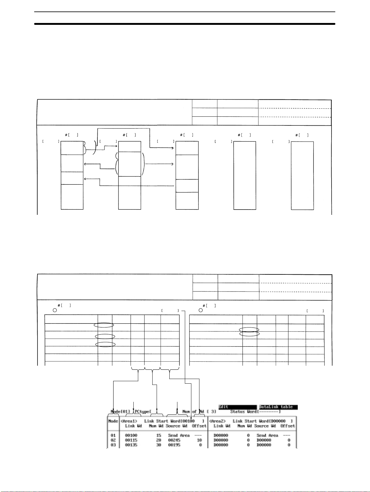
5-3SectionL: Data Link
Data Link Setting Forms
1, 2, 3... 1. Use Setting Form 1 to determine the data to be sent and received.
Controller Link Support Software
Data Link Setting Form1
Link start
word
00100
00115
00135
00149
Node
12 3
Line A errors,
#1, 15 wds
Line B errors,
#2, 20 wds
Line C errors,
#3, 15 wds
Offset
B
Link start
word
00215 00150
Line A errors,
#1, 15 wds
00225
10
Line B errors,
#2, 30 wds
20
00254
Before setting data link tables with the Controller Link Support Software, you
must determine how data is to be sent and received. Make an enlarged copy of
the Data Link Setting Forms provided in Appendix E and use them to design the
data link.
Node
Link start
word
00165
00195
00209
Date
System
Drawing No.
Node
Line A errors,
#1, 15 wds
Line B errors,
#2, 30 wds
Line C errors,
#3, 15 wds
Link start
word
___/___/___
Node
Comments:
Link start
word
Node
2. Use Setting Form 2 to enter the values to be set in the data link table.
3. Enter the values in the Controller Link Support Software.
Controller Link Support Software
Data Link Setting Form 2
1
Node
Area: 1 2
Data
Line A errors
Line B errors
Line C errors
Send/
Receive
Send/
Receive
Send/
Receive
Send/
Receive
Start word
at local
node
00100
00115
00135
Link start word
Source
node
–
#
#
2
#
3
#
#
Automatically
displayed
Number
of words
15
20
15
Date
System
Drawing No.
Node
00100 00215
Offset
–
10
0
Area: 1 2
Data
Line A errors
Line B errors
___/___/___ Comments:
2
Send/
Receive
Send/
Receive
Send/
Receive
Start word
at local
node
00215
00225
Link start word
Number
Source
of words
node
#
1–10
#
#
#
#
30
Automatically
displayed
Offset
5
–
49
Page 59

5-3SectionL: Data Link
Offsets
Offsets can be set by pressing the F6 (Offset) Key to display the “Offset” column
in the table. Offsets do not need to be set unless they are required.
In the “Offset” column, specify the offset for each reception node.
Setting Example
The following is an example of data link areas and the corresponding data link
tables.
Area 1 of Node 1 Area 1 of Node 2 Area 1 of Node 3
Node 1
(15 words)
Node 2
(20 words)
Node 3
(15 words)
Data Link Table for Node 1
Data Link Table for Node 2
Node 1
(10 words)
Node 2
(30 words)
Node 1
(15 words)
Node 2
(30 words)
Node 3
(15 words)
Receive area
Send area
50
Data Link Table for Node 3
Page 60

5-3-2 Setting Data Link Tables
Perform the following procedures to create and transfer data link tables.
1, 2, 3... 1. “Edit table” on page 52.
2. “Check table” on page 61.
3. “Transfer table” on page 67.
When necessary, use “Save table” and “Retrieve table” to save and retrieve data
link tables to/from files.
Note 1) Data link table data created or edited with the Controller Link Support Soft-
ware is recorded in the memory of the computer. The data will be lost when
the Controller Link Support Software is exited. To avoid this, use “Save
table” to save the data created or edited with “Edit table.”
2) If data link tables have already been saved or transferred, the following procedures can be used to read the tables to the Controller Link Support Software and edit them again.
“Retrieve table” on page 66.
“Controller Link → Computer” under the Transfer Table Menu on page 67.
5-3-3 Displaying the Data Link Menu
To create or edit a data link table or manage a data link, select the corresponding
function from the Data Link Menu. Each function is described on the following
pages. The following procedure shows how to display the Data Link Menu.
5-3SectionL: Data Link
51
Page 61
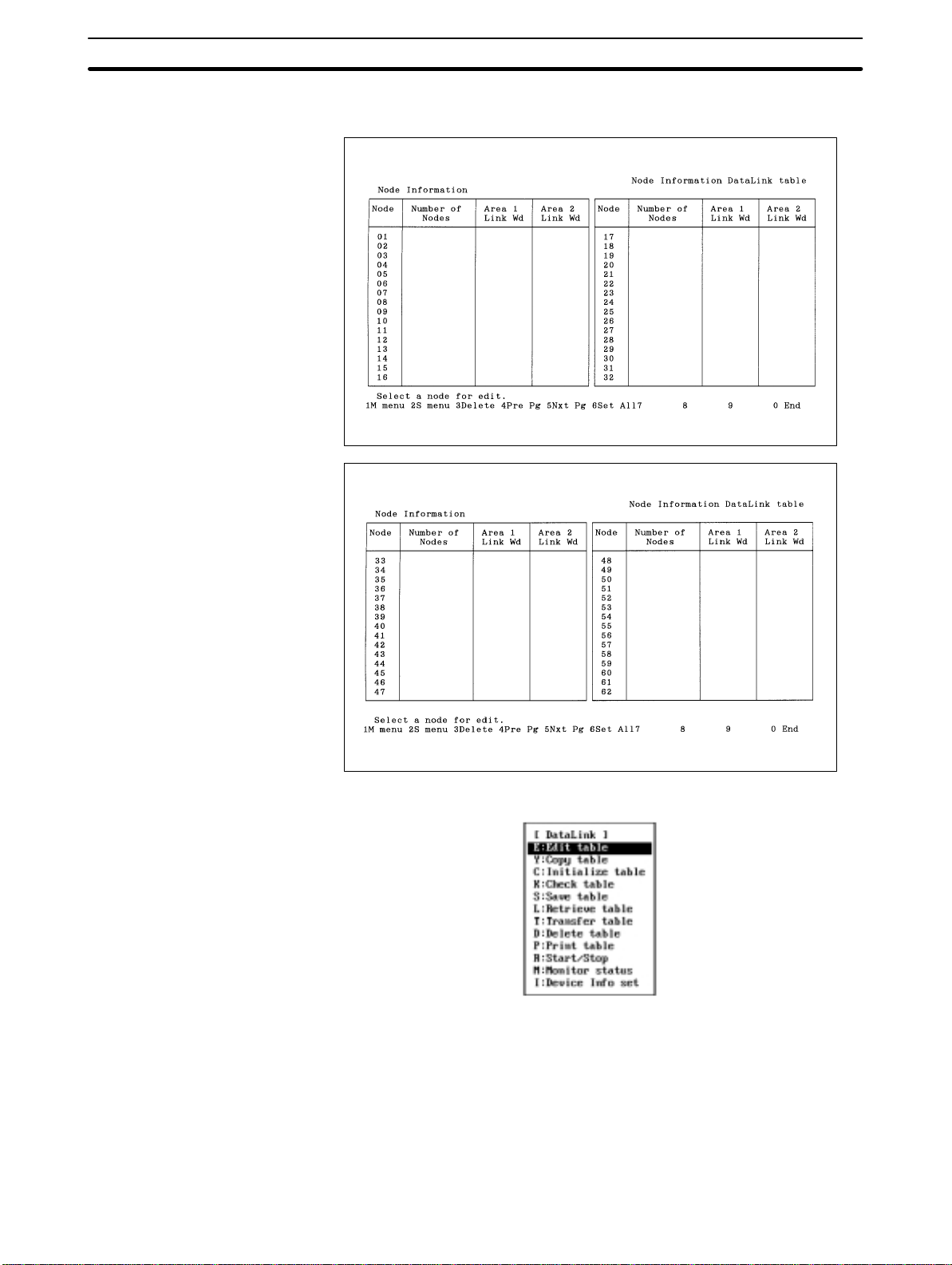
5-3SectionL: Data Link
1, 2, 3... 1. Select “L: Data Link” from the Main Menu. The Node Information Screen will
be displayed.
2. Press the F2 (Menu) Key. The Data Link Menu will be displayed.
5-3-4 Creating and Editing Data Link Tables — E: Edit Table
“E: Edit Table” is used to create or edit data link tables.
Note 1) “E: Edit Table” creates or edits data link tables in the computer memory . To
actually set the data link table at a node, select “T: Transfer table” from the
Data Link Menu. Also, save the data link tables as a file by selecting
“S: Save table” from the Data Link Menu. Otherwise, the table data will be
cleared when the Controller Link Support Software is exited.
52
Page 62

5-3SectionL: Data Link
2) The Controller Link Support Software allows you to edit data link tables for
all nodes within the network at the same time.
1, 2, 3... 1. Select “L: Data Link” from the Main Menu. The Node Information Screen will
be displayed.
The meaning of each display item is as follows:
Item Meaning
Number of Nodes Displays the number of send and receive areas (number of
Area 1 Link Wd Displays the total number of words in the data link area 1
Area 2 Link Wd Displays the total number of words in the data link area 2
nodes) specified in the data link table for each node.
for each node.
for each node.
These items are not displayed for a node for which a data link table has not
been set.
Press the F3 (Delete) Key or the Delete Key to delete the data link table for
the node in the cursor position. When either of these keys is pressed, a confirmation message will appear at the bottom of the screen. To delete the data
link table, press “Y” and then the Enter Key. To cancel the delete processing,
press “N” and then the Enter Key.
Press the F4 Key (Pre Pg), F5 Key (Nxt Pg), Page Up Key, or Page Down
Key to switch between the screen for nodes 1 to 31 and the screen for nodes
33 to 62.
Data link areas similar to automatically set areas can be easily created by
pressing the F6 (Set All) Key. See page 56 for details.
53
Page 63

5-3SectionL: Data Link
2. Select the node for which a data link table is to be created or edited. Use the
Cursor Keys to move the cursor to the node, then press the Enter Key. The
Data Link Table Screen for the specified node will be displayed.
The functions of the Function Keys differ depending on whether the cursor is
in a word address input field or in other input fields.
• The following Function Keys appear when the cursor is in a word address
input field
• The following Function Keys appear when the cursor is in other input fields
The screen can be switched to the Data Link Table Screen for a specified
node by mo v i n g t h e c u r sor to the “Node” field on the upper left of the screen
and entering the node address.
Key Function
F3 (Delete) Deletes the line on which the cursor is positioned.
F4 (Insert) Inserts one line before the line on which the cursor is
F6 (Offset) Switches between the offset display mode and no offset
F7 (Clear) Clears all the data link tables that are currently displayed.
F8 (Pre Nd) Displays the Data Link Table Screen for the previous
F9 (Nxt Nd) Displays the Data Link Table Screen for the next node.
positioned. The newly inserted line is for a node with the
next smallest unspecified address.
display mode. If an attempt is made to switch the mode
when offset data has already been entered, a
confirmation message will be displayed.
Press “Y” and then the Enter Key to set all the offsets to 0
and removes the offset displays. To cancel the operation,
press “N” and then the Enter Key.
When the F7 (Clear) Key is pressed, a confirmation
message will be displayed.
To clear the tables, press “Y” and then the Enter Key. To
cancel the operation, press “N” and then the Enter Key.
node.
54
3. Use the Cursor Keys to move the cursor to each field in the data link table
and enter appropriate data.
In the Data Link Table Screens, up to 16 lines can be displayed simultaneously. When setting 17 lines or more, the screen will automatically scroll.
Page 64

5-3SectionL: Data Link
If 17 or more lines have been set, the screen will automatically scroll up
(down) if the Page Up (Down) Key is pressed with the cursor in the top (bottom) line of the “Node” or “Num Wd” column.
To specify the data area, use the F3 (CIO/IR), F4 (LR), F5 (DM ), or F6 (EM)
Key.
Press “–” or the Delete Key in the first status word field to set the default value. Use Numeric Keys to enter numeric values.
The setting range for each item is as follows:
Item CS1-series PCs C200HX/HG/HE
Node 1 to 62
Link start
word
No. of
words
(Num Wd)
Offset 000 to 999
Status word CIO: 0001 to 6128
CIO: 0000 to 6143
LR: 000 to 199
(see note c)
DM: 00000 to
32767
(see note d)
EM (banks 0 to
12):
00000 to
32767
(see note d)
000 to 1000
LR: 000 to 184
(see note c)
DM: 00000 to
32752
(see note d)
EM (banks 0 to
12):
00000 to
32752
(see note d)
PCs
CIO: 000 to 235,
300 to 511
LR: 00 to 63
DM: 0000 to 5999
(see note d)
EM (banks 0 to
15):
0000 to 6143
(see note d)
CIO: 001 to 220,
300 to 496
LR: 00 to 48
DM: 0000 to 5984
(see note d)
EM (Banks 0 to
15):
0000 to 6128
(see note d)
CVM1 and
CV-series PCs
CIO: 0000 to 2555
LR: 000 to 199
(see note c)
DM: 00000 to
24575
(see note d)
EM (banks 0 to
7):
00000 to
32765
(see note d)
CIO: 0001 to 2540
LR: 000 to 184
(see note c)
DM: 00000 to
24560
(see note d)
EM (banks 0 to 7):
00000 to
32750
(see note d)
CQM1H PCs IBM PC/AT
CIO: 0000 to 247
LR: 00 to 63
DM: 0000 to 5999
(see note d)
EM: 0000 to 6143
(see note d)
CIO: 00000 to
65534
LR: 00000 to
65534
DM: 00000 to
65534
EM (banks 0 to 15):
00000 to
65534
(see note a)
CIO: 00000 to
65534
LR: 00000 to
65534
DM: 00000 to
65534
EM (banks 0 to 15):
00000 to
65534
CIO: 00000 to
65534
LR: 00000 to
65534
DM: 00000 to
65534
EM (banks 0 to 15):
00000 to
65534
Note a) Because IBM PC/AT or compatible computers have no data
areas, it is meaningless to specify first status words and link start
55
Page 65

5-3SectionL: Data Link
words for areas 1 and 2.The data link area always starts from the
beginning of the specified area, and data link status cannot be
read using functions or driver call. Computers do not have a specific areas.
b) In Wired Controller Link Networks, node addresses can only be
set in the range 1 to 32. The same restriction applies to Controller
Link Networks that consist only of Optical Controller Link Units
(with CLK11 at the end of the model number), or that consist of
both Optical Controller Link Units and Optical Ring Controller Link
Units (with CLK12 at the end of the model number). Node
addresses 1 to 62 can only be used in Controller LInk Networks
that consist of Optical Ring Controller Link Units only.
c) If a start word address is specified between LR 000 and LR 199 for
a CS1-series, CVM1, or CV-series PC, it will be allocated to the
CIO1000 to CIO1199.
d) The number of DM words and the number of EM banks differ ac-
cording to the CPU Unit model used. Refer to the PC operation or
programming manual for details.
Creating Simple Data
Link Areas — Set All
“Set All” can be used to simply create data link areas similar to automatically set
data link areas. An example is shown below.
Area 1
Area 2
Start word
Same size
Start word
Same size
After “Set All” is performed, highly flexible data link tables can be quickly created
by changing the link start word addresses, the number of send words, and the
number of receive words for each node.
With automatically set data links, only limited areas can be used for areas 1 and
2. With “Set All,” however, data areas can be freely selected for link areas 1
and 2.
With automatically set data links, data links must use the automatically created
data link areas. With “Set All,” the link start word, the number of send words, and
the number of receive words can be freely changed for each node later .
56
Page 66

5-3SectionL: Data Link
Differences “Set All” Automatic setting
Data area Can be freely selected for both
Link start word in
areas 1 and 2
Send area size
for each node
Receive-only
nodes
Send-only nodes
Node sequence
for data link
areas
Data link status
words
areas 1 and 2.
Can be freely specified for each area (this is the same for all
nodes).
Can be changed for each node
later.
Same size for each area
Can be changed for each node
later.
Cannot be specified by default.
Can be specified by changing
the data link area later.
Cannot be specified by default.
Can be specified by changing
the data link area later.
Automatically determined (ascending order)
Can be changed later by
deleting or inserting nodes.
Can be specified in CIO (IR),
DM, or EM.
Press the F6 (Set All) Key at the Node Information Screen to display the following window.
Area 1: CIO (IR)
Area 2: DM or EM
Cannot be changed later.
Cannot be changed later.
Cannot be specified.
Cannot be specified.
Cannot be changed later.
Can be specified only in CIO
(IR).
The items are almost the same as the items that are set in the DM parameter
area for automatic setting.
Item Meaning
Area 1 Link Start Word Specify the first word address of area 1.
Area 1 Link Word
Number
Area 2 Link Start Word Specify the first word address for area 2.
Area 2 Link Word
Number
Status Word Specify the first word of the words in which data link
Specify the number of words in the send area in each
node in area 1.
Specify the number of words in the send area in each
node in area 2.
status is to be stored.
The setting range for each item is as follows:
57
Page 67

5-3SectionL: Data Link
Item CS1-series PC C200HX/HG/ HE
Nodes in data
links
Area 1 Link Start
Word
Area 2 Link Start
Word
Area 1 Link Word
Number
Area 2 Link Word
Number
Status Word CIO: 0001 to
1 to 62
CIO: 0000 to
6143
LR: 000 to 199
(see note c)
DM: 00000 to
32767
(see note d)
EM (banks 0 to
12):
00000 to
32767
(see note d)
000 to 1000
6128
LR: 000 to 184
(see note c)
DM: 00000 to
32752
(see note d)
EM (banks 0 to
12):
00000 to
32752
(see note d)
CIO: 000 to 235,
LR: 00 to 63
DM: 0000 to
EM (banks 0 to
CIO: 001 to 220,
LR: 00 to 48
DM: 0000 to
EM (Banks 0 to
PC
300 to 511
5999
(see note d)
15):
0000 to
6143
(see note d)
300 to 496
5984
(see note d)
15):
0000 to
6128
(see note d)
CVM1 or
CV-series PC
CIO: 0000 to
2555
LR: 000 to 199
(see note c)
DM: 00000 to
24575
(see note d)
EM (banks 0 to
7):
00000 to
32765
(see note d)
CIO: 0001 to
2540
LR: 000 to 184
(see note c)
DM: 00000 to
24560
(see note d)
EM (banks 0 to
7):
00000 to
32750
(see note d)
CQM1-series PC IBM PC/AT
CIO: 0000 to 247
LR: 00 to 63
DM: 0000 to
5999
(see note d)
EM: 0000 to
6143
(see note d)
CIO: 00000 to
65534
LR: 00000 to
65534
DM: 00000 to
65534
EM (banks 0 to
15):
00000 to
65534
(see note a)
CIO: 00000 to
65534
LR: 00000 to
65534
DM: 00000 to
65534
EM (banks 0 to
15):
00000 to
65534
CIO: 00000 to
65534
LR: 00000 to
65534
DM: 00000 to
65534
EM (banks 0 to
15):
00000 to
65534
Note a) Because IBM PC/AT or compatible computers have no data
areas, it is meaningless to specify first status words and link start
words for areas 1 and 2.The data link area always starts from the
beginning of the specified area, and data link status cannot be
read using functions or driver call. Computers do not have a specific areas.
b) In Wired Controller Link Networks, node addresses can only be
set in the range 1 to 32. The same restriction applies to Controller
Link Networks that consist only of Optical Controller Link Units
(with CLK11 at the end of the model number), or that consist of
both Optical Controller Link Units and Optical Ring Controller Link
Units (with CLK12 at the end of the model number). Node
addresses 1 to 62 can only be used in Controller LInk Networks
that consist of Optical Ring Controller Link Units only.
c) If a start word address is specified between LR 000 and LR 199 for
a CS1-series, CVM1, or CV-series PC, it will be allocated to the
CIO1000 to CIO1199.
d) The number of DM words and the number of EM banks differ ac-
cording to the CPU Unit model used. Refer to the PC operation or
programming manual for details.
58
Page 68

5-3SectionL: Data Link
After the necessary items have been specified, press the F7 (Execute) Key to
display the following window in which the nodes to participate in the data link can
be selected.
Use the Cursor Keys to move the cursor to the nodes to participate in the data
links, then press the Enter Key. “Yes” will be displayed. An unmarked node will
not participate in the data links. Press the Enter Key at a node marked with “Yes”
to erase the “Yes.”
Press the F6 (Execute) Key to display the following window to prompt you to
specify whether the data link tables for the nodes not participating in the data
links are to be cleared or retained.
Press “Y” and then the Enter Key to erase the data link tables for the nodes not
participating in the data links and create data link areas (similar to the one for
automatically set data links) at each node participating in the data links.
Press “N” and then the Enter Key to retain the data link tables for the nodes not
participating in the data links and create data link areas (similar to the one for
automatically set data links) at each node participating in the data links.
Press the Escape Key to cancel the execution and return to the Node Information Screen. The execution can also be canceled by pressing the F1 (Menu) Key,
the F2 (Menu) Key, or the F10 (End) Key. The following screens are displayed
when these keys are pressed.
F1: Main Menu
F2: Data Link Menu
F10: Node Information Screen
5-3-5 Copying Data Link Tables — Y: Copy Table
“Y: Copy table” is used to copy a data link table for one node to other nodes.
When a similar data link area is to be used for other nodes, the data link table for
each node can be easily created by copying the original data link table and then
making changes.
Note 1) Once this copy function is executed, the existing data link table at the des-
tination node will be lost. Be sure to check table data at the destination node
before executing the function.
2) “Y: Copy table” copies data link tables in the computer memory. T o actually
set the data link table for a node, select “T: Transfer table” from the Data Link
Menu. Also, save the data link tables as a file by selecting “S: Save table”
from the Data Link Menu. Otherwise, the table data will be cleared when the
Controller Link Support Software is exited.
59
Page 69

3) Executing “Y: Copy table” also changes the node model specified in “Device
Info set” at the destination node to the same node model as the source node.
1, 2, 3... 1. Select “Y: Copy table” from the Data Link Menu.
2. Specify the source node address. Specify the node address with Numeric
Keys, then press the Enter Key. Any number between 1 and 62 can be specified.
If the number of nodes set in the data link table for the specified node is 0, an
error message will be displayed.
The following window will be displayed to prompt you to specify the destination node address.
5-3SectionL: Data Link
3. Specify the destination node address. Use the Cursor Keys to move the cursor to the copy destination node address, then press the Enter Key. “Yes”
will be displayed to represent the copy destination.
To deselect the copy destination node (or erase “Yes”), move the cursor to
the node address marked with “Yes,” then press the Enter Key again. “Yes”
will be erased to deselect the copy destination node.
4. After specifying all destination nodes, press the F6 (Execute) Key. The data
link tables will be copied.
5-3-6 Initializing All Data Link Tables — C: Initialize Table
“C: Initialize table” is used to initialize all data link tables.
When data link tables are to be created from scratch, initialize the data link tables
for all nodes before beginning.
Note 1) “C: Initialize table” initializes the data link tables in the computer memory.
2) Executing initializes the data link tables for all nodes. Initialization processing sets the “Link start word” field of area 1 to 00000, the “Link start word”
field of area 2 to D00000, and other settings to defaults.
1, 2, 3... 1. Select “C: Initialize table” from the Data Link Menu.
60
2. Press “Y” and then the Enter Key. The data link tables for all nodes will be
initialized.
Page 70

To cancel the initialization processing, press “N” and then the Enter Key.
5-3-7 Checking Data Link Tables — K: Check Table
“K: Check table” is used to check data link tables for errors or inconsistencies. It
can also check for inconsistencies between the data link tables for multiple
nodes.
If errors are detected, correct the data link tables as described in Error Mes-
sages (on page 63).
Note 1) Before executing “K: Check table,” always select “I: Device Info Set” from
the Data Link Menu and specify the PC models.
2) “K: Check table” checks the data link tables in the computer memory. To
check the data link table that has been set for a node, use “T: T ransfer table”
on the Data Link Menu to read the table to the computer, then execute
“K: Check table.”
1, 2, 3... 1. Select “K: Check table” from the Data Link Menu. If the number of nodes set
in all data link tables is 0, an error message will be displayed.
The following window will be displayed to prompt you to specify the check
level.
5-3SectionL: Data Link
2. Select the error level to be checked. The following window will be displayed
to prompt you to specify the nodes to be checked.
When the window appears, each node will be displayed as shown as follows, depending on the number of nodes set in the data link table in the
memory:
Nodes for which the number of nodes is not 0: YES (checked)
Nodes for which the number of nodes is 0: No display (not checked)
Error level Meaning
Rank A (error) Indicates serious errors.
If this level of error is detected, the data links will not
execute normally.
Rank B (warning) Indicates minor errors or the locations of settings that
could be faulty.
Even if this level of error is detected, the data links will
execute, but may result in unexpected operation. The
settings should be checked.
61
Page 71

5-3SectionL: Data Link
3. Specify the nodes to be checked. Use the Cursor Keys to move the cursor to
the node to be checked, then press the Enter Key. “Yes” will be displayed to
represent the nodes to be checked.
To deselect a node to be checked, move the cursor to a node marked with
“Yes,” then press the Enter Key again. “Yes” will be erased to deselect the
node.
4. After specifying all the nodes to be checked, press the F6 (Execute) Key.
The data link tables will be checked and the check results screen will be displayed.
Each error level is indicated by a different character color as follows:
Red: Error
White: Warning
A message is displayed in the lower part of the screen according to the
check results as follows:
When no errors has been detected: “Check OK”
When errors are continued on the next page: “Continue”
When the current page is the last page of the error display: “Last page”
5. When errors are displayed on multiple screens, use the following keys to
switch the screen and display the check results. F4 (Pre Pg), F5 (Nxt Pg), F8
(Pre Node), F9 (Nxt Node), Page Up, and Page Down
6. After confirming the check results, press the F10 (End) Key.
62
Page 72

Error Messages
Errors
5-3SectionL: Data Link
The following table lists the error messages that are displayed on the check results screen. After confirming the check results, use “E: Edit table” to correct the
data link tables, then check the data link tables again.
Message Meaning Action
Insufficient Status
area
Table Data error The first status word is
Duplicate Node
address
Link word number
over
Too many words in
data link
Link area overlap
error
Insufficient Link
area
(Area 1/ Area 2)
Link word number
0 error
There are too few words in
the data area for the data link
status.
outside the allowable range.
(see note)
The link start word address of
area 1 is outside the
allowable range. (see note)
The number of registered
nodes exceeds 62.
The node address is 0 or
more than 62.
There is a node for which the
send area or receive area for
one node exceeds 1,000
words.
An offset exceeds 999.
An offset for the send area of
the local node is not 0.
The same node address is
set more than once in the
data link table.
There is a node for which the
total number of words in the
send areas of areas 1 and 2
exceeds 1,000.
The total number of words in
the data link areas of areas 1
and 2 exceeds the maximum
allowable number of words for
the following PCs.
CS1-series PCs: 12,000
words
C200HX/HG/HE PCs: 8,000
words
CQM1H PCs: 8,000 words
CVM1 and CV-series PCs:
8,000 words
IBM PC/AT: 32,000 words
The same data area is
specified for areas 1 and 2.
The data link status words
overlap with a data link area.
There are not enough words
for the data link area.
The total number of link
words for one node is set to
0.
Change the first status word
so that data link status (16
words) can be stored in the
area.
Correct the values within the
allowable range as shown in
the table on page 55.
Correct the duplicate node
address.
Change the total number of
words in the send areas of
areas 1 and 2 to 1,000 or
less.
Reduce the total number of
words in the data link areas of
areas 1 and 2 to the
maximum allowable number
of words for the following PCs
or less.
CS1-series PCs: 12,000
words
C200HX/HG/HE PCs: 8,000
words
CVM1 and CV-series PCs:
8,000 words
IBM PC/AT: 32,000 words
Change the link start and first
status word of areas 1 and 2
so that the data link area and
the data link status words do
not overlap each other.
Correct the data link area
within the allowable range.
Set the number of link words
for area 1 or 2.
63
Page 73
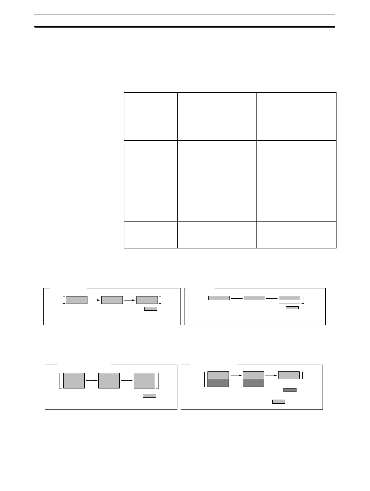
Warnings
Note Range checks are performed according to the model specified in
“Device Info set.” For C200HX/HG/HE PCs, no error will occur even if
a word address between CIO 236 and CIO 299, which are the outside
the allowable range, is specified. However, when the data link table is
transferred (or written) to the node, an error will occur. Use the Data
Link Table Edit Screen to check the word addresses.
Message Meaning Action
Recv area remain
(Area 1/ Area 2)
(see note a)
Recv area short
(Area 1/ Area 2)
(see note b)
Invalid offset
(Area 1/ Area 2)
Source node has
no send data
Source node has
no table
The number of words in the
receive area is greater than
that in the send area.
The number of words in the
receive area is fewer than
that in the send area.
The specified offset is outside
the send area.
A send area has not been set
for a node from which data
reception has been specified.
A data link table has not been
set at the node from which
data reception has been
specified.
Check the number of link
words. If free space is
intentionally left in the receive
area, the data link can be
executed without having to
make any changes.
Check the number of link
words. If only part of data in
the send area is to be
received, the data link can be
executed without having to
make any changes.
Check the offset. The data
link can be executed, but no
data can be received.
Change the reception node or
set a send area for that node.
Change the reception node or
set the data link table for that
node.
5-3SectionL: Data Link
Note a) Message “Receive area remain” will be displayed when the nu m -
ber of send words and the receive area are as shown in the following illustration.
Not remaining
Send
area
Node 1 Node 2 Node 1 Node 2
Receive
area
Data indicated by
is received in node 2.
Remaining
Send
area
Data indicated by
is received in node 2 and the
remaining words are cleared.
b) Message “Receive area short” will be displayed when the number
of send words and the receive area are as shown in the following
illustration.
Sufficient (not short)
Node 1 Node 2
Send
area
Receive
area
Data indicated by
is received in node 2.
Insufficient (short)
Node 1 Node 2
Send
area
Data indicated by
cannot be received in node 2.
Data indicated by
and the remaining data is truncated.
5-3-8 Saving Data Link Tables as a File — S: Save Table
“S: Save table” is used to save all data link tables as a file.
With Controller Link Support Software Ver. 2.00, data link tables can be saved in
the file formats shown below .
Receive
area
Receive
area
is received
64
Page 74

5-3SectionL: Data Link
Format Extension Saving supported
Controller Link Support
Software Ver. 2.00
Controller Link Support
Software Ver. 1.10
CX-Net on
CX-Programmer
Note 1) Data link tables containing node addresses in the range 33 to 62 cannot be
saved with Controller Link Support Software Ver. 1.10.
2) Unless saved, all data link tables in the memory will be lost wen the Controller Link Support Software is exited.
3) If data link tables have been modified but have not yet been saved, a confirmation message will be displayed when you attempt to exit the Controller
Link Support Software.
4) “S: Save table” saves the data link tables in the computer memory. To save
the data link tables that have already been set at nodes, select “T: Transfer
table” from the Data Link Menu to read the data link tables to the computer ,
then save the tables.
5) Data link table files for the Controller Link Support Software are not compatible with those for the conventional SYSMAC LINK Support Utility.
.CL2 Yes
.CLK Yes (see note 1)
.CL3 No
1, 2, 3... 1. Select “S: Save table” from the Data Link Menu.
2. Specify the file name (including the directory) to be saved. Enter the file
name with Alphanumeric Keys, then press the Enter Key.
Use the extension .CL2 for files to be saved in Ver. 2.00 format, and use the
extension .CLK for files to be saved in Ver. 1.10 format. (If an attempt to save
a file containing node addresses 33 to 62 is made with the extension .CLK,
an error will be generated.) If the extension is omitted by the user, it will be
added automatically depending on the node addresses used, in the following way.
• If node addresses 33 to 62 are used: .CL2.
• If node addresses 33 to 62 are not used: .CLK.
When this window appears, the data directory specified in “System setup”
will be displayed as the destination. The Insert, Backspace, and Delete
Keys can be used to correct the characters.
You can press the F8 (Files) Key to display the File Name List Screen and
then select a file name from the screen. (The extension can be changed
after the file is selected.)
If an existing file name is specified, a confirmation message will be displayed to ask you to check whether the file can be overwritten. Press “Y” to
overwrite the file or press “N” to cancel the save processing, then press the
Enter Key.
3. Enter a title for the file.
Enter the title with Alphanumeric Keys, then press the Enter Key. Up to 30
characters can be entered. The Insert, Backspace, and Delete Keys can be
used to correct the characters.
If no title is required, just press the Enter Key.
The file will be saved.
65
Page 75

5-3-9 Reading Data Link Tables from a File — L: Retrieve Table
“L: Retrieve table” is used to read data link tables from a file into computer
memory.
With Controller Link Support Software Ver. 2.00, data link tables can be saved in
the file formats shown below .
Format Extension Reading supported
Controller Link Support
Software Ver. 2.00
Controller Link Support
Software Ver. 1.10
CX-Net on
CX-Programmer
Note Data link tables in CX-Net format can be read but not saved.
There are differences in PC model information between the Controller Link Support Software and the CX-Net. Therefore, when reading CX-Net format files with
Controller Link Support Software, the data will be converted in the way shown in
the following table. When performing operations where a high degree of precision is required, such as when checking data link tables, reset as necessary.
.CL2 Yes
.CLK Yes
.CL3 Yes (see note 1)
5-3SectionL: Data Link
Model information in CX-Net on
CX-Programmer
No specification No specification
C200HE C200HE(-Z)
C200HG C200HG(-Z)
C200HX C200HX
CVM1 CVM1-CPU21
CV2000 CV2000
CV1000 CV1000
CV500 CV500
NSB CLK Board
CS1G CS1G-45
CS1H CS1H-67
CVM1-V2 CVM1-CPU21
C200HX-Z C200HX-85Z
C00HG-Z C200HG(-Z)
C200HE-Z C200HE(-Z)
IDSC No specification
Model information in Controller LInk
Support Software
Note 1) If data link tables are read from a file, the current data link tables in the
memory will be lost.
66
2) If data link tables in the memory have been modified, a confirmation window
will be displayed when you attempt to read data link tables from the file.
3) Data link table files for the Controller Link Support Software are not compatible with those for the SYSMAC LINK Support Utility.
1, 2, 3... 1. Select “L: Retrieve table” from the Data Link Menu. If data link tables in the
memory have been modified, a confirmation window will be displayed.
Press “Y” to continue or press “N” to cancel the process, and then press the
Enter Key . If data link tables i n the memory have not been modified or “Y” is
Page 76

5-3SectionL: Data Link
pressed to continue, the following window will be displayed to prompt you to
specify a file name.
2. Specify the file name (including the directory) to be read. Enter the file name
with Alphanumeric Keys, then press the Enter Key.
When reading files, specify the extension .CL2 for Ver. 2.00 format files,
.CLK for Ver. 1.10 format files, or .CL3 for CX-Net format files. If an extension
is not specified, a search for the specified file-name in the specified directory
will be made and if a corresponding file is found it will be read. If more than
one file of the same name is found then priority will be in the following order:
1. .CLK (Ver. 1.10 format)
2. .CL2 (Ver. 2.00 format)
3. .CL3 (CX-Net format)
For example, if two files with the same name are found, and one of the files
has the extension .CLK and the other one has the extension .CL2, the one
with the .CLK will be read.
When this window appears, the data directory specified in “System setup”
will be displayed as the source directory. The Insert, Backspace, and Delete
Keys can be used to correct the characters displayed.
You can press the F8 (Files) Key to display the File Name List Screen and
then select a file name from the screen.
The file will be read.
5-3-10Transferring Data Link Tables — T: Transfer Table
“T: Transfer table” is used to transfer data link tables between nodes and the
computer as follows:
Item Function Page
Displaying the Transfer
Data Link Table Menu
Reading Data Link Tables
from Nodes —
R: Controller Link →
Computer
R: Controller Link → Computer Reads the data link tables set at
W: Computer → Controller Link Writes the data link tables from the
V: Compare Compares the data link tables set
Select “T: Transfer table ” from the Data Link Menu. The Transfer Data Link table
Menu will be displayed.
“R: Controller Link → Computer” is used to read the data link tables at nodes into
the computer memory.
Note If data link tables are read from nodes, the current data link tables in the comput-
er memory will be lost. If data link tables in the memory have been modified, a
confirmation window will be displayed when you attempt to read data link tables
from the nodes. To save the data link tables in the memory , select “S: Save table”
from the Data Link Menu to save them as a file.
nodes to the computer memory.
computer memory to nodes for
registration.
at nodes with the data link tables in
the computer memory.
67
69
71
1, 2, 3... 1. Select “R: Controller Link → Computer” from the Transfer Data Link table
Menu. If data link tables in the memory have been modified, a confirmation
67
Page 77

5-3SectionL: Data Link
window will be displayed. Press “Y” to continue or press “N” to cancel the
process, then press the Enter Key. If data link tables in the memory have not
been modified or “Y” is pressed to continue, the following window will be displayed to prompt you to specify the target nodes.
2. Specify the address of the Controller Link Network containing the nodes
from which data link tables are to be read. Enter the network address with
Numeric Keys, then press the Enter Key. When the Enter Key is pressed, the
nodes on the specified network will be checked and displayed in ascending
order of node address.
When node addresses are displayed, all nodes will be marked with YES,
which represents the target nodes for reading.
3. Specify the nodes that are to be excluded from read processing. Use the
Cursor Keys to move the cursor to the nodes to be excluded from reading,
then press the Enter Key. YES will be erased to deselect the node. To reselect a node for reading, move the cursor to the node unmarked with YES,
then press the Enter Key again. YES will be displayed to reselect the node.
68
4. After specifying all the target nodes for reading, press the F6 (Execute) Key.
The transfer results screen will be displayed and data link table read proces-
Page 78
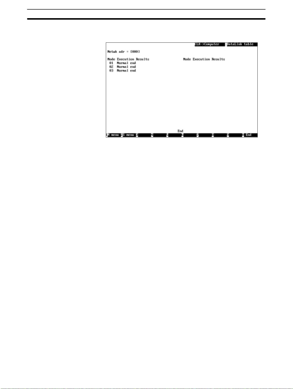
sing will start. Data link tables will be read in ascending order of node address.
To cancel the read processing, press the F9 (Cancel) Key.
During read processing, “Wait” will be displayed in the lower part of the
screen and the progress of processing will be displayed for each node.
When read processing for all the specified nodes is completed, “End” will be
displayed in the lower part of the screen.
5. Then, press the F10 (End) Key.
5-3SectionL: Data Link
Writing Data Link Tables
to Nodes — W: Computer
→ Controller Link
“W: Computer → Controller Link” is used to write the data link tables from the
computer memory to nodes.
Note 1) If data link tables are written to nodes, the existing data link tables set at the
nodes will be lost. In this case, a confirmation message for overwriting will
not be displayed even if data link tables have already been set at the nodes.
Therefore, carefully check the contents of the data link tables set at the
nodes before transferring new data link tables.
When writing data to the CS1-series PC, be sure to set pin 1 of the CPU
Unit’s DIP switch to OFF.
2) When writing data link tables to a CVM1 or CV-series PC, always set the
system protect key switch on the CPU Unit to NORMAL.
3) “W: Computer → Controller Link” can also be used to delete the data link
tables for the nodes that are not participating in the data link. Always delete
unused data link tables.
4) Data link tables can be written to nodes only when the nodes are not participating in active data links or when the data links are inactive.
69
Page 79

5-3SectionL: Data Link
1, 2, 3... 1. Select “W: Computer → Controller Link” from the Transfer Data Link table
Menu. The following window will be displayed to prompt you to specify the
target nodes.
2. Specify the address of the Controller Link Network containing the nodes to
which data link tables are to be written. Enter the network address with Numeric Keys, then press the Enter Key.
When the Enter Key is pressed, the nodes on the specified network will be
checked and displayed in ascending order of node address.
When node addresses are displayed, Yes or No will be displayed as follows,
depending on the number of nodes set in the data link table in the memory:
Nodes for which the number of nodes is not 0: Yes (data link tables written)
Nodes for which the number of nodes is 0: No (data link tables removed)
3. Specify the processing for each node. Use the Cursor Keys to move the cursor to the node, then press the Enter Key. Each time the Enter Key is
pressed, the display will change in the following order.
Yes (data link tables written)
↓
No (data link tables removed)
↓
No display (nothing done, i.e., data link tables not transferred nor removed)
↓
Yes (data link tables written)
4. After specifying the processing for each node, press the F6 (Execute) Key.
The transfer results screen will be displayed and data link tables will be written or removed as specified.
70
Page 80

The processing will be performed in ascending order of node address.
To cancel the processing, press the F9 (Cancel) Key.
During the processing, “W ait” will be displayed in the lower part of the screen
and the progress of processing will be displayed for each node.
In write processing, each data link table will be simultaneously checked for
serious errors or link offset errors. If an error is detected in a data link table, a
window will be displayed to ask you to determine whether the data is to be
written to the node. Press “Y” to write the data or press “N” to cancel the write
processing, and then press the Enter Key. If “N” is pressed to cancel the
write processing, “Canceled due to table error” will be displayed at the node
address.
When processing for all the specified nodes is completed, “End” will be displayed at the lower part of the screen.
5. Then, press the F10 (End) Key.
5-3SectionL: Data Link
Comparing Data Link
T ables — V: Compare
“V: Compare” is used to compare data link tables in the computer memory with
data link tables set at each node.
1, 2, 3... 1. Select “V: Compare” from the Transfer Data Link Table Menu. The following
window will be displayed to prompt you to specify the nodes for which data
link tables are to be compared with those in the memory.
71
Page 81

5-3SectionL: Data Link
2. Specify the address of the Controller Link Network containing the nodes for
which data link tables are to be compared. Enter the network address with
Numeric Keys, then press the Enter Key.
When the Enter Key is pressed, the software will check the nodes on the
specified network and display only the nodes that exist in the network and
for which the number of nodes specified in the data link table in the memory
is not 0. These nodes will be displayed in ascending order of node address.
When node addresses are displayed, YES will be displayed at each node
address to represent the target nodes for comparison.
3. Select the nodes to be excluded from comparison. Use the Cursor Keys to
move the cursor to the node to be excluded from comparison, then press the
Enter Key. YES will be erased to deselect the node.
To reselect a node for comparison, move the cursor to the node unmarked
with YES, then press the Enter Key again.
the node.
YES will be displayed to reselect
4. After specifying all the target nodes for comparison, press the F6 (Execute)
Key. The transfer results screen will be displayed and data link table comparison will start. Comparison will be performed in ascending order of node
address.
To cancel the comparison, press the F9 (Cancel) Key.
During comparison, “Wait” will be displayed in the lower part of the screen
and the progress of processing will be displayed for each node.
If a comparison error is detected in a node, the node address and the execu-
tion results will be highlighted.
72
Page 82

5-3SectionL: Data Link
If no comparison error is detected in all the specified nodes, “Compare OK”
will be displayed. In this case, press the F10 (End) Key to quit the comparison.
If comparison errors are detected, message “Will display differences. Specify node address” will be displayed along with the mode number of the smallest node address with a comparison error.
5. Specify the node address of the node for which the comparison errors are to
be displayed. Enter the network address with Numeric Keys, then press the
Enter Key. The comparison error screen for the specified node will be displayed.
The comparison error screen differs depending on the location of the error.
• The following will be displayed when an inconsistency is found in the num-
ber of nodes set, first status word, link start word of area 1, or link start word
of area 2.
When the number of nodes set is inconsistent, the number of words in area
1, offset in area 1, the number of words in area 2, and offset in area 2 will
not be compared.
• The following will be displayed when an inconsistency is found in the num-
ber of words in area 1, offset in area 1, number of words in area 2, or offset
in area 2.
73
Page 83

The message for the comparison results will be displayed in the lower part of
the screen as follows:
When comparison errors continue on the next page: “Continue”
When the comparison error screen is the last page: “Last page”
When inconsistent data is found, the data in the memory will be displayed i n
the upper row and the data at the node will be displayed in the lower row.
(Consistent data will not be displayed.)
6. If the comparison error screen extends across more than one page, use the
F4 (Pre Pg) and F5 (Nxt Pg) Keys to switch the screen and display the results. The Page Up and Page Down Keys can also be used to switch the
screen.
To display the comparison errors for another node, press the Escape Key to
exit from the comparison error screen, then repeat the procedure from
step 5.
7. After checking the comparison results, press the F10 (End) Key.
5-3-11Deleting Data Link Tables from Nodes — D: Delete Table
“D: Delete table” is used to delete the data link tables set at one or more nodes.
Note 1) Data link tables cannot be deleted from a node that is currently participating
in the data links.
2) The nodes for which the number of nodes set in the data link table in the
computer memory is 0 will be automatically selected as the nodes from
which data link tables are to be deleted. Therefore, data link tables can be
deleted from only the nodes that are not to participate in the data links. You
can also change the target nodes for deletion.
3) Always delete the data link tables from the nodes that are not be participating in the data links.
1, 2, 3... 1. Select “D: Delete table” from the Data Link Menu. The following window will
be displayed to prompt you to specify the nodes from which data link tables
are to be deleted.
5-3SectionL: Data Link
74
2. Specify the address of the Controller Link Network containing the nodes
from which data link tables are to be deleted. Enter the network address with
Numeric Keys, then press the Enter Key.
When the Enter Key is pressed, the nodes on the specified network will be
checked and displayed in ascending order of node address.
When node addresses are displayed, YES or No will be displayed as follows, depending on the number of nodes set in the data link table in the
memory:
Nodes for which the number of nodes is not 0: YES (data link tables deleted)
Nodes for which the number of nodes is 0: No display (data link tables not
deleted)
Page 84

5-3SectionL: Data Link
3. Specify the processing for each node. Use the Cursor Keys to move the cursor to the node for which the processing is to be changed, then press the
Enter Key.
Each time the Enter Key is pressed, the display will change as follows:
YES (data link tables deleted)
µ
No display (data link tables not deleted)
4. After specifying all the nodes from which data link tables are to be deleted,
press the F6 (Execute) Key. The deletion results screen will be displayed
and data link table delete processing will start.
Data link tables will be deleted in ascending order of node address.
To cancel the delete processing, press the F9 (Cancel) Key.
During delete processing, “Wait” will be displayed in the lower part of the
screen and the progress of processing will be displayed for each node.
When the delete processing for all the specified nodes is completed, “End”
will be displayed in the lower part of the screen.
5. Then, press the F10 (End) Key.
5-3-12Printing Data Link Tables — P: Print Table
“P: Print table” is used to print the data link tables in the computer memory.
Note Select “Printer model” from the System Setup Menu and specify the printer mod-
el before using “P: Print table.”
75
Page 85

5-3SectionL: Data Link
1, 2, 3... 1. Select “P: Print table” from the Data Link Menu. The following window will be
displayed to prompt you to specify the nodes for which the data link tables
are to be printed.
This window displays the nodes for which the number of nodes set in the
data link table in the memory is not zero. These nodes are displayed in ascending order of node address and YES is displayed at each node address
to represent the nodes for which data link tables are to be printed.
2. Select the nodes to be excluded from printing. Use the Cursor Keys to move
the cursor to the node to be excluded from printing, then press the Enter Key.
YES will be erased to deselect the node.
To reselect a node for printing, move the cursor to the node unmarked with
YES, then press the Enter Key again. YES will be displayed to reselect the
node.
3. After specifying all the target nodes for print processing, press the F6
(Execute) Key. Data link table printing will start and the print status display
window will appear. Data link tables will be printed in ascending order of
node address.
To cancel the printing, press the F9 (Cancel) Key.
“Printing” will be displayed during printing.
When printing for all the specified nodes is completed, the print status dis-
play window will close and the processing will automatically terminate.
During printing, the print position will be automatically adjusted so that the
data link table for one node is not split.
The contents of the data link table being printed are the same as those dis-
played on the Node Information List and Data Link Table Screens. The presence or absence of the “Offset” column also depend son the data link table
conditions.
76
Page 86

See 5-3-4 Creating and Editing Data Link Tables (page 52) for details on
printing.
Printing Example
5-3SectionL: Data Link
5-3-13Starting and Stopping Data Links — R: Start/Stop
“R: Start/Stop” is used to start and stop data links.
Caution Before starting data links, make sure that the data link tables for each node for
!
manually set data links, or the data link parameters at the data link start node for
automatically set data links, have been appropriately set. If the settings are inappropriate, the equipment may perform unexpected operation and result in injury.
Even if the settings are appropriate, always make sure that the equipment will
not be affected before starting or stopping the data links.
Note Before starting the data links, always check the data link mode (manual or auto-
matic) set at the node from which the data links are to be started.
77
Page 87

1, 2, 3... 1. Select “R: Start/Stop” from the Data Link Menu.
2. Select “R: Start” to start the data links or “S: Stop” to stop the data links.
Example for “R: Start”
3. Specify the node to start or stop the data links. Use the Cursor Keys to move
the cursor to each field (“PC ID,” “Network address,” and “Node address”),
then enter a numeric value with Numeric Keys (enter a PC ID with Alphanumeric Keys).
Press the Enter Key to register the input item and move the cursor to the next
field.
5-3SectionL: Data Link
Item Meaning
PC ID Enter the PC ID of the node.
Use this field only when a PC ID is to be used. If a PC ID is
used, the network address and node address will be specified
automatically (see page 124).
Network address Enter the network address of the node.
The setting range is between 0 and 127.
Network address 0 represents the local network (the address
of the network containing the node to which the Controller
Link Support Software is connected). (see note)
For CS1-series, CVM1, or CV-series PCs with multiple
Communications Units, specify the network address explicitly.
Node address Enter the node address of the node.
The setting range is between 0 and 62.
Node address 0 represents the local node (the address of the
node to which the Controller Link Support Software is
connected).
Note For CVM1 or CV-series CPU Units manufactured before April 1996
(lot No.: jj46), always set routing tables. Specify in the “Network
address” the value (other than 0) specified in the routing tables. Refer
to the Controller Link Units Operation Manual (W309) for details.
Press the F10 (End) Key to cancel the data link start/stop procedure.
4. Press the F6 (Execute) Key. The data links for the specified network will be
started or stopped.
5-3-14Displaying Data Link Status — M: Monitor Status
“M: Monitor status” is used to check data link operations.
Item Meaning Page
S: Monitor Data Link
status
78
Displays data link operating status for
the specified node.
79
Page 88

5-3SectionL: Data Link
Displaying the Monitor
Data Link Status Menu
Displaying Data Link
Status — S: Monitor Data
Link Status
1, 2, 3... 1. Select “S: Monitor Data Link status” from the Monitor Data Link status
To use each status monitor functions, select the desired function from the Monitor Data Link Status Menu. Select “M: Monitor status” from the Data Link Menu.
The Monitor Data Link Status Menu will be displayed.
“S: Monitor Data Link status” is used to display the data link operating status for
the specified node.
Menu.
2. Specify the node for which the data link status is to be displayed. Use the
Cursor Keys to move the cursor to each field (“PC ID,” “Network address,”
and “Node address”), then enter a numeric value with Numeric Keys (enter a
PC ID with Alphanumeric Keys).
Press the Enter Key to register the input item and move the cursor to the next
field.
Item Meaning
PC ID Enter the PC ID of the node.
Use this field only when a PC ID is to be used. If a PC ID is
used, the network address and node address will be input
automatically(see page 124).
Network address Enter the network address of the node.
The setting range is between 0 and 127.
Network address 0 represents the local network (the address
of the network containing the node to which the Controller
Link Support Software is connected). (see note)
For CS1-series, CVM1, or CV-series PCs with multiple
Communications Units, specify the network address explicitly.
Node address Enter the node address of the node.
The setting range is between 0 and 62.
Node address 0 represents the local node (the address of the
node to which the Controller Link Support Software is
connected).
Note For CVM1 or CV-series CPU Units manufactured before April 1996
(lot No.: jj46), always set routing tables. Specify in “Network address” the value (other than 0) specified in the routing tables. Refer to
the Controller Link Units Operation Manual (W309) for details.
Press the F10 (End) Key to cancel the data link start/stop procedure.
3. Press the F6 (Execute) Key. Data link status will be read from the specified
node and operating status will be displayed on the real-time basis.
79
Page 89

5-3SectionL: Data Link
Note The nodes registered in the data link table for the specified node are
highlighted. They are the nodes that have data links to the specified
node.
Key Function
F4 (Pre Pg)
Page Up
F5 (Nxt Pg)
Page Down
F9 (Cancel) Stops updating the display and changes the F9 Key
F9 (Start) Restarts updating the display and changes the F9 Key
F10 (End) Closes the operating status display screen.
When this key is pressed, the node addresses for which
the node status is displayed will change cyclically in the
following order:
1 to 16 → 17 to 32 → 33 to 48 → 49 to 62
When this key is pressed, the node addresses for which
the node status is displayed will change cyclically in the
following order:
49 to 62 → 33 to 48 → 17 to 32 → 1 to 16
function to “Start.”
function to “Cancel.”
The meaning of each item is as follows:
Item Meaning
Communications
cycle time
(Comm cycle
time)
Data link
(DataLink)
Refresh cycle
time
(Refresh cycle)
Data link table
(DataLink table)
Displays the current communications cycle time of the
Controller Link Network.
Displays the data link operating status, active/inactive on
the top and manual/automatic on the bottom.
Displays the current data link refresh time (the period from
the time the data link data is refreshed at the PC until the
next refresh is completed) and the maximum data link
refresh time that has been measured since the data links
were started.
For nodes with a Controller Link Support Board, the refresh
cycle time is always 0 ms.
Displays whether data link tables have been set at the
nodes displayed on the screen.
80
Page 90

Item Meaning
PC run
(PC Run)
PC error
(PC err)
Communications
error
(Comm err)
Data link join
(DtLnk join)
Offset error
(offset err)
Area short
(Area short)
Area remaining
(Area remain)
Displays the operating status of PC on the network as
follows:
When user program is not running on PC: No display
When user program is running on PC: YES
YES will be always displayed for nodes with a Controller
Link Support Board.
Displays error status of each PC on the network as follows:
When the PC is operating normally or is not participating in
the data link: No display
When the PC has a fatal or nonfatal error: YES
Displays the communications status of each node on the
network as follows:
When the node is communicating normally: No display
When the node has caused a cyclic communications error
or is not participating in the network: YES
Displays the data link participation status of each node on
the network as follows:
When the node is not participating in the data link due to
data link table error or other errors: No display
When the node is participating in the data link: YES
Displays offset error status in the data link table for node
communications within the network as follows:
When there is no offset error: No display
When there is an offset error: YES
An offset error occurs when the offset value is greater than
the number of send words.
Displays area shortage status in the data link tables for
node communications within the network as follows:
When the area is sufficient: No display
When the area is short: YES
When the data link is inactive: No display.
A short area occurs when the receive area is smaller than
the amount of send data and not all of the send data can be
received. It is not a fatal error. If the receive area
intentionally receives only part of the send data, it can be
used without having to make any changes.
Displays remaining area in the data link table for node
communications within the network as follows:
When the area does not remain empty: No display
When words in the area remain empty: YES
Remaining area occurs when the receive area is larger
than the amount of send data and extra space remains
unfilled after reception. The remaining space will be cleared
with 0s. This is not a serious error. If the receive area
intentionally provides extra space, it can be used without
having to make any changes.
5-3SectionL: Data Link
5-3-15Specifying Node Models — I: Device Information Settings
“I: Device Info set” is used to specify the models of the nodes that comprise the
Controller Link Network. The specified data is saved as a file.
The Controller Link Support Software performs word address validity checking
according to the node model information specified in “Device Info set.”
Note 1) Model information for all nodes is unspecified (left blank) immediately after
the Controller Link Support Software is initially started.
81
Page 91

2) Executing “Initialize table” makes the model information for all nodes unspecified (blank).
1, 2, 3... 1. Select “I: Device Info set” from the Data Link Menu.
2. Select the node for which model is to be specified. Use the Cursor Keys to
move the cursor to the target node, then press the Enter Key or the F6 (Select) Key.
Press the F7 (Fill) Key to select all nodes.
Press the F3 (Delete) Key or the Delete Key to delete the model information
for the node in the cursor position.
5-3SectionL: Data Link
82
Note a) If “Others” is selected, restrictions for each model will no longer
apply. Regardless of the model, restrictions will apply to only the
upper limits when numeric values are entered or checked.
b) New PCs that do not appear in the model list can be displayed and
selected from Controller Link Support Software by editing the device information setting file (see Appendix E Editing the Device In-
formation Setting File).
c) The version of the Controller Link Support Software is displayed
on the logo screen when the software is started.
3. Select the model to be set. Use the Cursor Keys to move the cursor to the
model to b e set, then press the Enter Key. The specified model will be set for
the specified node. (Press the F7 Key to set the specified model for all the
nodes.)
4. After specifying the models for all the nodes, press the F10 (End) Key. The
model setting procedure will end.
Page 92

5-4 P: Set Network Parameters
“P: Set Network parameters” is used to modify network communications parameters to provide the most suitable Controller Link communications for the user
application.
Note 1) Network parameters cannot be set during data link operation. Set the net-
work parameters after stopping the data links. (See 5-3-13 Starting and
Stopping Data Links on page 77.)
2) The same network parameters are used for all nodes within the Controller
Link Network. Therefore, any change in each network parameters will affect
all nodes within the network.
3) Before executing “P: Set Network parameters”, always set pin 1 of the DIP
switch on the CS1-series and CQM1H-series CPU Unit to OFF.
4) Before executing “P: Set Network parameters”, always set the system pro-
tect key switch on the CVM1 or CV-series CPU Unit to NORMAL.
1, 2, 3... 1. Select “P: Set Network parameters” from the Main Menu.
2. Specify the address of the Controller Link Network for which network parameters are to be changed. Enter the network address with Numeric Keys, then
press the Enter Key. The current network parameter settings for the specified network will be displayed.
5-4SectionP: Set Network Parameters
83
Page 93

5-4SectionP: Set Network Parameters
3. Specify the new values for the network parameters. Use the Cursor Keys to
move the cursor to the desired field, then enter a value with Numeric Keys.
Press the Enter Key to register a new value and move the cursor to the next
field.
Item Meaning
Maximum node
address
(Max node address)
Number of
Event-frames per
communications
cycle
(# of Event-frames
per comm cycle)
Number of Polled
nodes per
communications
cycle
(# of Polled nodes
per comm cycle)
Maximum node address of nodes that are checked by the
network polling node. Any node with a node address greater
than this setting will not participate in the network.
Unnecessary polling (connection checking) can be avoided
by setting the maximum node address of the nodes to be
checked.
The setting range is between 2 and 62.
The default is 62.
Maximum amount of event data (such as message service
data) that can be transmitted during a communications cycle
Increasing the value also increases the communications
cycle time.
Too small a value results in frequent transmission timeout
errors.
The setting range is between 16 and 238.
The default is 35.
Maximum number of nodes for which communications
status can be checked by the network polling node during a
communication cycle
Increasing the value also increases the communications
cycle time but provides quicker response to nodes
participating in or leaving the network.
The setting range is between 1 and 61.
The default is 4.
Press the F7 (Initialize) Key to set each item to its default.
Note If the Controller Link Network consists of Units other than Optical
Ring Controller Link Units, do not set node addresses higher than 32.
(Node addresses higher than 32 can only be set for Controller Link
Networks that consist of only Optical Ring Controller Link Units.)
4. Press the F6 (Execute) Key. A confirmation message will be displayed at the
bottom of the window.
5. Press “Y” and then the Enter Key. The network parameter settings will be
modified.
To cancel the processing, press “N” and then the Enter Key.
84
Page 94

5-5 R: Routing Table
“R: Routing table” is used to manage the routing tables used for determining
communications paths between multiple networks. It has the following menu.
E: Edit Creates or edits routing tables. Routing tables
K: Check Checks the routing tables in the memory for
C: Initialize Initializes (or clears) the routing tables in the
S: Save Saves routing tables in the memory as a file. 93
L: Retrieve Reads routing tables from the file into the
T: Transfer Writes routing tables from the memory to the
D: Delete Deletes routing tables from the specified
P: Print Prints routing tables in the memory. 99
5-5SectionR: Routing Table
Menu item Function Page
88
are created in the computer memory. To set
the routing tables for each node, execute
“T: Transfer.”
91
errors or inconsistencies.
93
memory. Use this item when routing tables
are to be created from scratch.
94
memory.
94
specified node or reads routing tables from
the specified node into the memory. This item
can also be used to compare the routing
tables in the memory with the routing tables
at the specified node.
98
node.
85
Page 95

5-5-1 Outline of Routing Tables
Routing tables must be set when the local node communicates with PCs, computers, and other nodes on remote networks. Routing tables need not be set
when the node communicates only with other nodes on the local network.
Note For CVM1 or CV-series CPU Units manufactured before April 1996 (lot No.:
jj46), always set routing tables. Refer to the Controller Link Units Operation
Manual (W309) for details.
5-5SectionR: Routing Table
About Routing Tables
Routing tables define communications paths when a local node communicates
with nodes on remote networks.
The following is a network example and the data required to create routing tables
is explained below.
Computer
Programming Device
(Controller Link Support
Software)
Controller Link Network
(network 1)
Controller Link Unit
(unit number 0)
SYSMAC NET
(network 2)
Gateway
SYSMAC NET Link Unit
Controller Link Unit
(node address 5)
In this network example, when the PC connected to the Programming Device on
network 1 is t o communicate with a PC on network 2, you need to create routing
tables containing the following information and transfer them to the PCs and
computer on network 2.
86
• The local node belongs to network 1 (local network).
• The unit number of the Communications Unit is 0 (link unit number).
• Communications is performed via the Communications Unit with node ad-
dress 5 that belongs to network 1 (relay node).
• The local node communicates with the remote network via network 1 (relay
network).
• The local node communicates with a node on network 2 (end network).
Routing Tables for PC (A)
Local Network Table
Local network Link unit number
001 00
Relay Network Table
End network Relay network Relay node
002 001 005
Page 96

5-5-2 Setting Routing Tables
Create and transfer routing tables for each node according to the following setting procedures.
1, 2, 3... 1. “Edit” on page 88.
2. “Check” on page 91.
3. “Save” on page 93.
4. “Computer → PC/Board” under “Transfer” on page 96.
Caution Once routing tables are transferred to a PC, all CPU Bus Units at the node (ex-
!
cept SYSMAC BUS/2 Master Units) will be reset. Before transferring the routing
tables, always make sure that the equipment will not be affected.
Note 1) If routing tables have already been saved or transferred, the following pro-
cedures can be used to read the routing tables into the Controller Link Support Software and edit them again.
“Retrieve” on page 94.
“PC/Board → Computer” under “Transfer” on page 95.
2) The Controller Link Support Software can create and transfer routing tables
for all nodes supporting FINS commands, as well as for the Controller Link
Units and Controller Link Support Boards. It cannot create or transfer routing tables for PCs for which the SYSMAC NET Link Unit is set to C Mode
even if these PCs are CVM1 or CV-series PCs. In this case, connect the
SYSMAC Support Software directly to such nodes and create and transfer
routing tables.
3) The Controller Link Support Software can set a local network table containing up to 16 entries and a relay network table containing up to 20 entries. For
C200HX/HG/HE PCs, a maximum of two entries can be made in the local
network table.
5-5SectionR: Routing Table
5-5-3 Communications Range
Network
Communications Range
Relay Nodes
The Controller Link Support Software can communicate with nodes on a Controller Link Network via OA networks (Ethernet networks) or F A networks (Controller Link, SYSMAC NET, and SYSMAC LINK networks) to set or monitor the
Controller Link Units and Controller Support Boards at remote nodes.
The Controller Link Support Software can communicate with up to three networks.
Running from a Programming Device
Computer running the
Controller Link Support
Software
The connection to the
PC is not counted as
a network level.
Only CS1-series, CVM1, and CV-series PCs can be used as nodes for relaying
between networks. Install multiple Communications Units on a PC to relay between networks.
C-series PCs and IBM PC/AT computers cannot be used as relay nodes (but can
be used as source and destination nodes).
SYSMAC NET Network (2nd network)
Controller Link Network
(1st network: local)
Controller Link Network (3rd network)
4 Network levels
are not possible
Controller Link Network (4th network)
87
Page 97

5-5-4 Displaying the Routing Table Menu
To create or edit routing tables, select the corresponding function from the Routing Table Menu.
Each function is described on the following pages. The Routing Table Menu is
displayed as follows:
1, 2, 3... 1. Select “R: Routing table” from the Main Menu. The routing table (local net-
work table) will be displayed.
5-5SectionR: Routing Table
2. Press the F2 (Menu) Key. The Routing Table Menu will be displayed.
5-5-5 Creating and Editing Routing Tables — E: Edit
“E: Edit” is used to create or edit the routing tables: the local network table and
the relay network table.
Note 1) “E: Edit” creates or edits routing tables in the computer memory. To actually
set the routing tables at a node, select “T: Transfer” from the Routing Table
Menu. Also, save the routing tables as a file by selecting “S: Save” from the
Routing Table Menu. The table data will be cleared when the Controller Link
Support Software is exited.
2) The Controller Link Support Software can create routing tables for only one
node at a time. If routing tables for more than one node are to be created,
save the created routing tables for a node, then create routing tables for the
next node.
88
Page 98

5-5SectionR: Routing Table
1, 2, 3... 1. Select “E: Edit” from the Routing Table Menu. The Local Network Table
Screen will be displayed. The Local Network Table Screen can also be displayed by selecting “R: Routing table” from the Main Menu.
2. Set the local network table. Use the Cursor Keys to move the cursor to the
desired position, then enter a numeric value with Numeric Keys.
Press the Enter Key to register the entered value and move the cursor to the
next position.
Item Meaning
Loc Netwk Specify the address of the network to which the
SIOU unit # Specify the unit number of the Communications Unit or
Communications Unit or Board installed at the target node
belongs.
The setting range is between 1 and 127.
Be careful not to specify the same network address for more
than one network.
Board that is installed at the target node and is connected to
the local network.
The setting range is between 0 and 15.
With Controller Link, the unit number is set in the following
locations.
Communications Unit: Rotary switch on the front panel of
the Unit for CS1-series, CVM1, and
CV-series PCs
DIP switch pin 4 on the front panel
of the Unit for C200HX/HG/HE
PCs)
(Fixed to 0 for CQM1H PCs.)
Communications Board: Option switch on Controller Link
BIOS (device driver)
Enter the same unit number as the above setting.
Press the F6 (Insert) Key or the Insert Key to insert one blank line before the
cursor line. (Y ou cannot move the cursor until you enter s a value in the “Loc
Netwk” column on the blank line.)
Press the F7 (Delete) Key or the Delete Key to delete the line on which the
cursor is currently positioned.
3. After entering all the necessary values in the local network table, press the
F4 (Pre Pg) Key or the F5 (Nxt Pg) Key. The Relay Network Table Screen will
be displayed.
89
Page 99

5-5SectionR: Routing Table
Press the Page Up Key or the Page Down Key to switch between the Local
Network Table Screen and the Relay Network Table Screen.
4. Set the relay network table. Use the Cursor Keys to move the cursor to the
desired position, then enter a numeric value with Numeric Keys. (Use Alphanumeric Keys to enter the PC ID of each relay node.)
Press the Enter Key to register the entered value and move the cursor to the
next position.
Item Meaning
End Network Specify the address of the destination network.
The setting range is between 1 and 127.
Be careful not to specify the same network address for two
different networks.
Relay PC ID Specify the PC ID of the relay node.
This entry is valid only when PC IDs are used. If PC IDs are
used, network and node addresses are automatically input
(see page 124.)
Relay network Specify the network address of the relay node. Enter one of
Relay node Specify the node address of the relay node.
the values specified in the “Loc Netwk” column of the Local
Network Table.
The setting range is between 1 and 127.
The setting range is between 1 and 126 (or between 1 and
62 for Controller Link Networks). (see note)
Note The setting range for Controller Link Units other than Optical Ring
Controller Link Units is between 1 and 32.
Press the F6 (Insert) Key or the Insert Key to insert one blank line before the
cursor line. (You cannot move the cursor until you enter a value in the “End
Netwk” column on the blank line.)
Press the F7 (Delete) Key or the Delete Key to delete the line on which the
cursor is currently positioned.
5. After entering all the necessary values in the relay network table, press the
F10 (End) Key.
Even if the Relay Network Table Screen is switched to another screen, the
contents of t he routing table will be retained until the Controller Link Support
Software is exited.
To return to the Local Network Table Screen, use the F4 (Pre Pg) Key, F5
(Nxt Pg) Key, Page Up Key, or Page Down Key.
90
Page 100

5-5-6 Checking Routing Tables — K: Check
“K: Check” is used to check the routing tables for errors or inconsistencies. If errors are detected, correct the routing tables as described in Error Messages (on
page 92).
Note “K: Check” checks the routing tables in the computer memory. To check the rout-
ing tables that have been set at a node, use “T: Transfer” on the Routing Table
Menu to read the tables to the computer, then execute “K: Check.”
1, 2, 3... 1. Select “K: Check” from the Routing Table Menu. The routing table check will
start and the check results screen will be displayed.
5-5SectionR: Routing Table
A message will be displayed in the lower part of the screen according to the
check results as follows:
When no error has been detected: “Check OK”
When errors are continued on the next page: “Continue”
When the current screen is the last page: “Last page”
2. When errors are displayed on multiple screens, use the F4 (Pre Pg) Key, the
F5 (Nxt Pg) Key, the Page Up Key, or the Page Down Key to switch the
screen and display the check results. After confirming the check results,
press the F10 (End) Key.
91
 Loading...