

Page 1

PROFIBUS-DP Master Unit
OPERATION MANUAL
Cat. No. W349-E2-2
C200HW-PRM21
Page 2

Page 3

Page 4

Page 5

C200HW-PRM21
PROFIBUS-DP Master Unit
Operation Manual
Produced May 2000
Page 6

iv
Page 7

Notice:
!
Caution
!
DANGER!
!
WARNING
OMRON products are manufactured for use according to proper procedures by a qualified operator
and only for the purposes described in this manual.
The following conventions are used to indicate and classify precautions in this manual. Always heed
the information provided with them. Failure to heed precautions can result in injury to people or damage to the product.
Indicates information that, if not heeded, is likely to result in loss of life or serious injury.
Indicates information that, if not heeded, could possibly result in loss of life or serious injury.
Indicates information that, if not heeded, could result in relatively serious or minor injury,
damage to the product, or faulty operation.
OMRON Product References
All OMRON products are capitalised in this manual. The word “Unit” is also capitalised when it refers to
an OMRON product, regardless of whether or not it appears in the proper name of the product.
The abbreviation “Ch,” which appears in some displays and on some OMRON products, often means
“word” and is abbreviated “Wd” in documentation in this sense.
The abbreviation “PLC” means Programmable Logic Controller and is not used as an abbreviation for
anything else.
Visual Aids
The following headings appear in the left column of the manual to help you locate different types of
information.
OMRON, 2000
All rights reserved. No part of this publication may be reproduced, stored in a retrieval system, or transmitted, in any
form, or by any means, mechanical, electronic, photocopying, recording, or otherwise, without the prior written
permission of OMRON.
No patent liability is assumed with respect to the use of the information contained herein. Moreover, because OMRON is
constantly striving to improve its high-quality products, the information contained in this manual is subject to change
without notice. Every precaution has been taken in the preparation of this manual. Nevertheless, OMRON assumes no
responsibility for errors or omissions. Neither is any liability assumed for damages resulting from the use of the
information contained in this publication.
Note Indicates information of particular interest for efficient and convenient operation
of the product.
1, 2, 3…Indicates lists of one sort or another, such as procedures, checklists, etc.
v
Page 8

vi
Page 9

TABLE OF CONTENTS
PRECAUTIONS .........................................................................................xi
1 Intended Audience........................................................................................................................................................xii
2 General Precautions......................................................................................................................................................xii
3 Safety Precautions ........................................................................................................................................................xii
4 Operating Environment Precautions.............................................................................................................................xii
5 Application Precautions...............................................................................................................................................xiii
6 EC Directives ..............................................................................................................................................................xiv
1 PROFIBUS-DP......................................................................................1
1-1 Introduction..............................................................................................................................................................2
1-2 Protocol architecture ................................................................................................................................................2
1-3 Device types.............................................................................................................................................................4
1-4 PROFIBUS-DP characteristics.................................................................................................................................4
1-5 Device Data Base files .............................................................................................................................................8
1-6 Profiles.....................................................................................................................................................................8
2 INSTALLATION.................................................................................. 9
2-1 Physical layout of the unit......................................................................................................................................10
2-2 Mounting the C200HW-PRM21 ............................................................................................................................13
2-3 Setting up a network...............................................................................................................................................14
3 SPECIFICATIONS AND PERFORMANCE..................................17
3-1 Overall Specifications............................................................................................................................................18
3-2 Performance ...........................................................................................................................................................20
4 CONFIGURATOR.............................................................................29
4-1 General...................................................................................................................................................................30
4-2 Setup ......................................................................................................................................................................31
4-3 Operation................................................................................................................................................................32
4-4 Debug mode...........................................................................................................................................................46
5 PLC INTERFACE..............................................................................51
5-1 Unit Settings...........................................................................................................................................................52
5-2 Input / Output Mailbox...........................................................................................................................................59
5-3 Control and status area...........................................................................................................................................60
5-4 LEDs ......................................................................................................................................................................70
6 MESSAGE COMMUNICATION, IOWR / IORD .........................73
6-1 Message communication........................................................................................................................................74
6-2 IOWR.....................................................................................................................................................................74
6-3 IORD......................................................................................................................................................................76
6-4 Messages................................................................................................................................................................77
7 TROUBLESHOOTING AND MAINTENANCE ...........................83
7-1 Error Indicators ......................................................................................................................................................84
7-2 Troubleshooting .....................................................................................................................................................84
7-3 Maintenance...........................................................................................................................................................90
vii
Page 10

Appendices ..................................................................................................93
Appendix A Tips and sample programs....................................................................................................93
Appendix B GSD file for C200HW-PRM21 ..........................................................................................101
Appendix C CS1 PLC series compatibility.............................................................................................103
Index ..........................................................................................................105
Revision History .......................................................................................107
viii
Page 11

About this Manual:
!
WARNING
This manual describes the installation and operation of the PROFIBUS-DP Master Unit and includes the
sections described below.
Please read this manual carefully and be sure you understand the information provided before attempting to install and operate the PROFIBUS-DP Master Unit. Be sure to read the precautions provided
in the following section.
Section 1 gives a brief description of PROFIBUS-DP.
Section 2 describes the installation of the C200HW-PRM21.
Section 3 describes the overall specifications and the communication performance of the Unit.
Section 4 describes the software for configuring the PROFIBUS-DP network.
Section 5 describes the interface with the user.
Section 6 describes the message communication.
Section 7 describes the troubleshooting procedures and maintenance operations.
Failure to read and understand the information provided in this manual may result in
personal injury or death, damage to the product, or product failure. Please read
each section in its entirety and be sure you understand the information provided in
the section and related sections before attempting any of the procedures or
operations given.
ix
Page 12

x
Page 13

PRECAUTIONS
This section provides general precautions for using the PROFIBUS-DP Master Units, Programmable Controllers, and
related devices.
The information contained in this section is important for the safe and reliable application of the PROFIBUS-DP
Master Units. You must read this section and understand the information contained before attempting to set up or
operate a PROFIBUS-DP Master Unit and PLC system.
1 Intended Audience........................................................................................................................................................xii
2 General Precautions......................................................................................................................................................xii
3 Safety Precautions ........................................................................................................................................................xii
4 Operating Environment Precautions.............................................................................................................................xii
5 Application Precautions...............................................................................................................................................xiii
6 EC Directives ..............................................................................................................................................................xiv
xi
Page 14

Operating Environment Precautions
!
WARNING
!
WARNING
!
WARNING
1 Intended Audience
This manual is intended for the following personnel, who must also have
knowledge of electrical systems (an electrical engineer or the equivalent).
• Personnel in charge of installing FA systems.
• Personnel in charge of designing FA systems.
• Personnel in charge of managing FA systems and facilities.
2 General Precautions
The user must operate the product according to the performance
specifications described in the operation manuals.
Before using the product under conditions which are not described in the
manual or applying the product to nuclear control systems, railroad systems,
aviation systems, vehicles, combustion systems, medical equipment,
amusement machines, safety equipment, and other systems, machines, and
equipment that may have a serious influence on lives and property if used
improperly, consult your OMRON representative.
Make sure that the ratings and performance characteristics of the product are
sufficient for the systems, machines, and equipment, and be sure to provide
the systems, machines, and equipment with double safety mechanisms.
This manual provides information for installing and operating OMRON
PROFIBUS-DP Master Units. Be sure to read this manual before operation
and keep this manual close at hand for reference during operation.
It is extremely important that a PLC and all PLC Units be used for the
specified purpose and under the specified conditions, especially in
applications that can directly or indirectly affect human life. You must consult
with your OMRON representative before applying a PLC system to the above
mentioned applications.
3 Safety Precautions
Never attempt to disassemble any Units while power is being supplied. Doing
so may result in serious electrical shock or electrocution.
Never touch any of the terminals while power is being supplied. Doing so may
result in serious electrical shock or electrocution.
4 Operating Environment Precautions
Do not operate the control system in the following places.
• Where the PLC is exposed to direct sunlight.
• Where the ambient temperature is below 0°C or over 55°C.
• Where the PLC may be affected by condensation due to radical
temperature changes.
• Where the ambient humidity is below 10% or over 90%.
• Where there is any corrosive or inflammable gas.
• Where there is excessive dust, saline air, or metal powder.
• Where the PLC is affected by vibration or shock.
• Where any water, oil, or chemical may splash on the PLC.
xii
Page 15

Application Precautions
The operating environment of the PLC System can have a large effect on the
!
Caution
!
Caution
!
Caution
!
WARNING
longevity and reliability of the system. Improper operating environments can
lead to malfunction, failure, and other unforeseeable problems with the PLC
System. Be sure that the operating environment is within the specified
conditions at installation and remains within the specified conditions during
the life of the system.
5 Application Precautions
Observe the following precautions when using the PROFIBUS-DP Master
Units or the PLC.
Failure to abide by the following precautions could lead to serious or possibly
fatal injury. Always heed these precautions.
• Always ground the system to 100 Ω or less when installing the system to
protect against electrical shock.
• Always turn OFF the power supply to the PLC before attempting any of the
following. Performing any of the following with the power supply turned ON
may lead to electrical shock:
• Mounting or removing any Units (e.g., I/O Units, CPU Unit, etc.) or
memory cassettes.
• Assembling any devices or racks.
• Connecting or disconnecting any cables or wiring.
Failure to abide by the following precautions could lead to faulty operation of
the PLC or the system or could damage the PLC or PLC Units. Always heed
these precautions.
• Use the Units only with the power supplies and voltages specified in the
operation manuals. Other power supplies and voltages may damage the
Units.
• Take measures to stabilise the power supply to conform to the rated supply
if it is not stable.
• Provide circuit breakers and other safety measures to provide protection
against shorts in external wiring.
• Do not apply voltages exceeding the rated input voltage to Input Units. The
Input Units may be destroyed.
• Do not apply voltages exceeding the maximum switching capacity to Output
Units. The Output Units may be destroyed.
• Always disconnect the LG terminal when performing withstand voltage
tests.
• Install all Units according to instructions in the operation manuals. Improper
installation may cause faulty operation.
• Provide proper shielding when installing in the following locations:
• Locations subject to static electricity or other sources of noise.
• Locations subject to strong electromagnetic fields.
• Locations subject to possible exposure to radiation.
• Locations near power supply lines.
• Be sure to tighten Backplane screws, terminal screws, and cable connector
screws securely.
• Do not attempt to take any Units apart, to repair any Units, or to modify any
Units in any way.
The following precautions are necessary to ensure the general safety of the
system. Always heed these precautions.
• Provide double safety mechanisms to handle incorrect signals that can be
xiii
Page 16

6 EC Directives
generated by broken signal lines or momentary power interruptions.
• Provide external interlock circuits, limit circuits, and other safety circuits in
addition to any provided within the PLC to ensure safety.
PROFIBUS-DP Master Units that meet EC directives also meet the common
emission standard (EN50081-2). When PROFIBUS-DP Master Units are built
into equipment, however, the measures necessary to ensure that the
standard is met will vary with the overall configuration, the other devices
connected, and other conditions. You must therefore confirm that EC
directives are met for the overall machine or device.
xiv
xiv
Page 17

1 PROFIBUS-DP
This section gives a brief description of PROFIBUS-DP.
1-1 Introduction................................................................................................................................................................2
1-2 Protocol architecture ..................................................................................................................................................2
1-3 Device types...............................................................................................................................................................4
1-4 PROFIBUS-DP characteristics ..................................................................................................................................4
1-4-1 Bus Access Protocol .........................................................................................................................................4
1-4-2 Data throughput...............................................................................................................................................5
1-4-3 Diagnostics functions .......................................................................................................................................6
1-4-4 Protection mechanisms.....................................................................................................................................6
1-4-5 Network states ..................................................................................................................................................7
1-5 Device Data Base files ...............................................................................................................................................8
1-6 Profiles.......................................................................................................................................................................8
1
Page 18

Introduction
!
Caution
1-1 Introduction
Multi-vendor
Standard
EN 50170
High speed
Process Automation
Section 1-1
PROFIBUS is a vendor-independent, open fieldbus standard for a wide range
of applications in manufacturing, process and building automation. Vendor
independence and openness are guaranteed by the PROFIBUS standard
EN 50170. With PROFIBUS, devices of different manufacturers can
communicate without special interface adjustments.
The PROFIBUS family consists of three compatible versions:
PROFIBUS-DP
DP stands for Decentralised Periphery. It is optimised for high speed and low-
cost interfacing, especially designed for communication between automation
control systems and distributed I/O at the device level.
PROFIBUS-PA
PA stands for Process Automation. It permits sensors and actuators to be
connected on one common bus line even in intrinsically-safe areas. It permits
data communication and power supply over the bus using 2-wire technology
according the international standard IEC 1158-2.
Higher level
Uniform bus access protocol
PROFIBUS-FMS
FMS stands for Fieldbus Message Specification. This version is the general-
purpose solution for communication tasks at a higher level. Powerful services
open up a wide range of applications and provide great flexibility. It can also
be used for extensive and complex communications tasks.
PROFIBUS-DP and PROFIBUS-FMS use the same transmission technology
and a uniform bus access protocol. Thus, both versions can be operated
simultaneously on the same cable. However, FMS field devices cannot be
controlled by DP masters or vice versa.
It is not possible to exchange one of these family members by another family
member. This will cause faulty operation.
The rest of this section only describes PROFIBUS-DP.
1-2 Protocol architecture
OSI
The PROFIBUS protocol architecture is oriented on the OSI (Open System
Interconnection) reference model in accordance with the international
standard ISO 7498. Layer 1 (physical layer) of this model defines the physical
transmission characteristics. Layer 2 (data link layer) defines the bus access
protocol. Layer 7 (application layer) defines the application functions.
2
Page 19

Protocol architecture
Section 1-2
DP-Profiles
DP-Extensions
User Interface Layer DP Basic Functions
(7) Application Layer
(6) Presentation Layer
(5) Session Layer NOT DEFINED
(4) Transport Layer
(3) Network Layer
(2) Data Link Layer Fieldbus Data Link (FDL)
(1) Physical Layer RS-485 / Fibre Optics
Layer 1, 2 and user interface
Transmission medium
High-speed, inexpensive
Easy installation
Cable length
PROFIBUS-DP uses layers 1 and 2, and the user interface. Layers 3 to 7 are
not defined. This streamlined architecture ensures fast and efficient data
transmission. The application functions which are available to the user, as
well as the system and device behaviour of the various PROFIBUS-DP device
types, are specified in the user interface. RS-485 transmission technology or
fibre optics are available for transmission. RS-485 transmission is the most
frequently used transmission technology. Its application area includes all
areas in which high transmission speed and simple inexpensive installation
are required. Twisted pair shielded copper cable with one conductor pair is
used.
The RS-485 transmission technology is very easy to handle. Installation of the
twisted pair cable does not require expert knowledge. The bus structure
permits addition and removal of stations or step-by-step commissioning of the
system without influencing the other stations. Later expansions have no effect
on stations which are already in operation.
Transmission speeds between 9.6 kbit/s and 12 Mbit/s can be selected. One
unique transmission speed is selected for all devices on the bus when the
system is commissioned.
The maximum cable length depends on the transmission speed (see table
below). The specified cable lengths are based on type-A cable (see
section 2-3-1). The length can be increased by the use of repeaters. The use
of more than 3 repeaters in series is not recommended.
Baud rate (kbit/s) Distance/segment (m)
9.6 1200
19.2 1200
93.75 1200
187.5 1000
500 400
1500 200
3000 100
6000 100
12000 100
3
Page 20

Device types
1-3 Device types
Master devices
Active stations
DPM1, DPM2
Slave devices
Passive stations
Section 1-3
PROFIBUS distinguishes between master devices and slave devices.
Master devices determine the data communication on the bus. A master can
send messages without an external request when it holds the bus access
rights (the token). Masters are also called active stations in the PROFIBUS
protocol.
There are two types of master devices: DP master class 1 (DPM1) and DP
master class 2 (DPM2). A DPM1 is a central controller which exchanges
information with the decentralised stations (i.e. DP slaves) within a specified
message cycle. DPM2 devices are programmers, configuration devices or
operator panels. They are used during commissioning for configuration of the
DP system or for operation and monitoring purposes.
Slave devices are peripheral devices. Typical slave devices include
input/output devices, valves, drives and measuring transmitters. They do not
have bus access rights and they can only acknowledge received messages or
send messages to the master when requested to do so. Slaves are also
called passive stations.
The C200HW-PRM21 is a DPM1 device.
1-4 PROFIBUS-DP characteristics
1-4-1 Bus Access Protocol
Layer 2
Medium Access Control
Token passing
Polling procedure
The bus access protocol is implemented by layer 2. This protocol also
includes data security and the handling of the transmission protocols and
telegrams.
The Medium Access Control (MAC) specifies the procedure when a station is
permitted to transmit data. The token passing procedure is used to handle the
bus access between master devices and the polling procedure is used to
handle the communication between a master device and its assigned slave
device(s).
The token passing procedure guarantees that the bus access right (the token)
is assigned to each master within a precisely defined time frame. The token
message, a special telegram for passing access rights from one master to the
next master must be passed around the logical token ring - once to each
master - within a specified target rotation time.
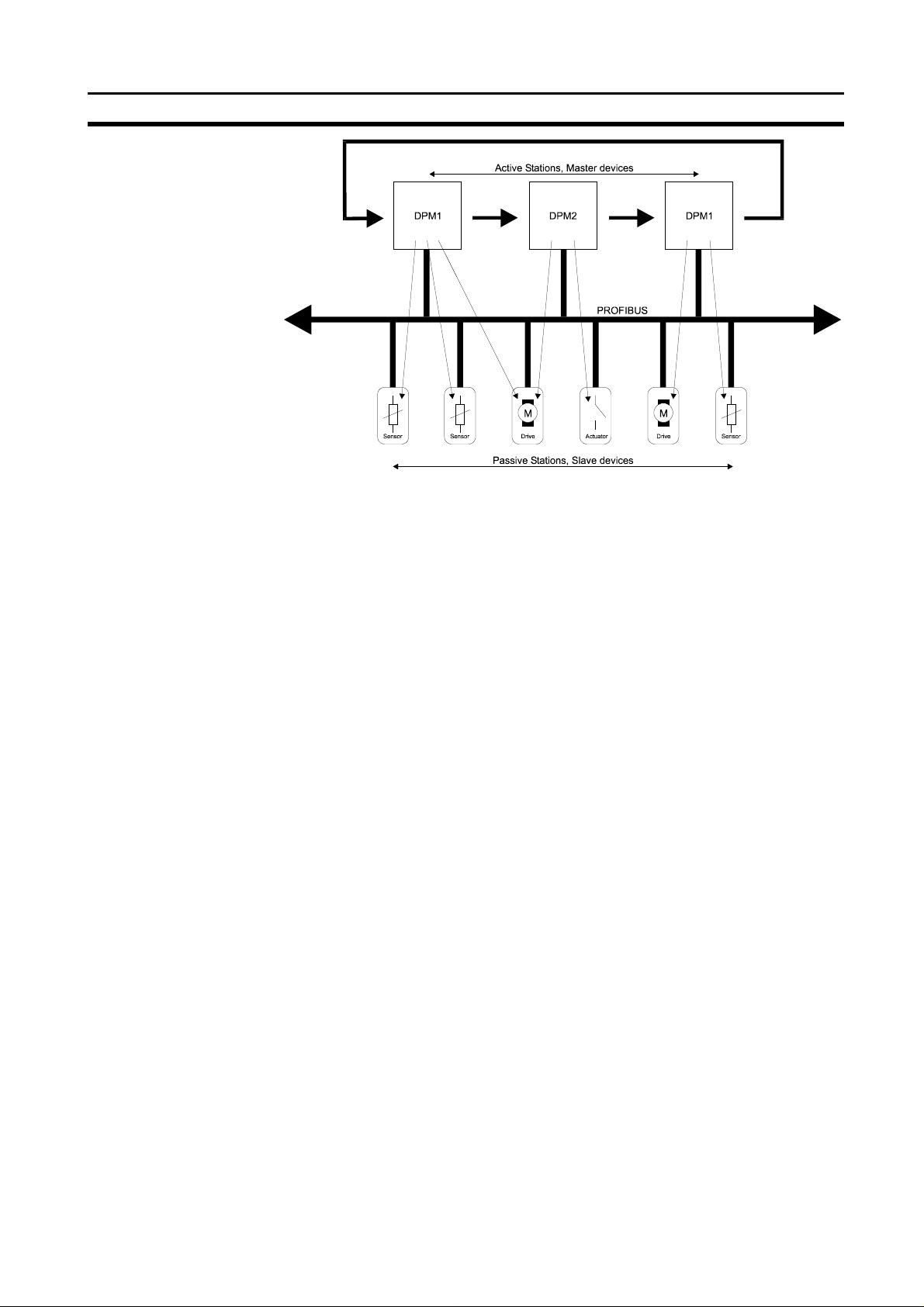
The polling or master-slave procedure permits the master, which currently
owns the token, to access the assigned slaves. The picture below shows a
possible configuration.
4
Page 21
PROFIBUS-DP characteristics
The configuration shows three active stations (masters) and six passive
stations (slaves). The three masters form a logical token ring. When an active
station receives the token telegram, it can perform its master role for a certain
period of time. During this time it can communicate with all assigned slave
stations in a master-slave communication relationship and a DPM2 master
can communicate with DPM1 master stations in a master-master
communication relationship.
Multi-peer communication
In addition to logical peer-to-peer data transmission, PROFIBUS-DP provides
multi-peer communication (broadcast and multicast).
Broadcast communication: an active station sends an unacknowledged
Multicast communication: an active station sends an unacknowledged
Section 1-4
message to all other stations (master and
slaves).
message to a predetermined group of stations
(master and slaves).
1-4-2 Data throughput
Transmission time
At 12 Mbit/s PROFIBUS-DP requires only about 1 ms for the transmission of
512 bits of input data and 512 bits of output data distributed over 32 stations.
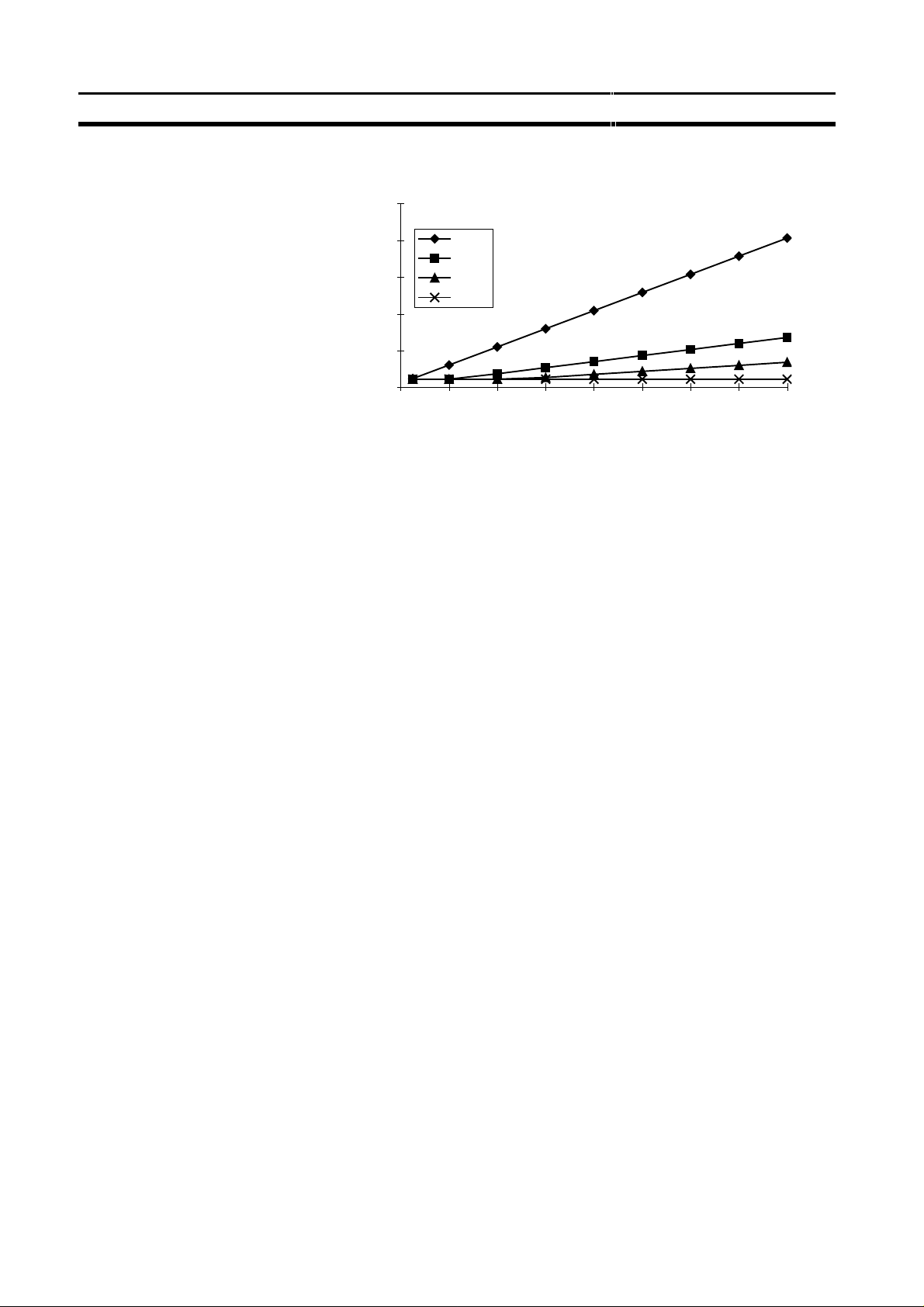
The figure below shows the typical PROFIBUS-DP transmission time
depending on number of stations and transmission speed. The data
throughput will decrease when more than one master is used.
5
Page 22
PROFIBUS-DP characteristics
Bus cycle time vs number of slaves
Section 1-4
25.0
Bus cycle time [ms]
Conditions: Each slave has 2 bytes of input data and 2 bytes of output data.
1-4-3 Diagnostics functions
Extensive diagnostics
Device related diagnostics
Module related diagnostics
Channel related diagnostics
The extensive diagnostic functions of PROFIBUS-DP enable fast location of
faults. The diagnostic messages are transmitted over the bus and collected at
the master. These messages are divided into three levels:
• Device related diagnostics
These messages concern the general operational status of the whole
device (i.e. overtemperature or low voltage).
• Module related diagnostics
These messages indicate that a fault is present in a specific I/O range
(e.g. an 8-bit output module) of a station.
• Channel related diagnostics
These messages indicate an error at an individual input or output (e.g.
short circuit on output 5).
20.0
15.0
10.0
5.0
0.0
0 4 8 12 16 20 24 28 32
500
1500
3000
12000
Slaves
1-4-4 Protection mechanisms
Time monitoring
At the master
At the slave
6
PROFIBUS-DP provides effective protection functions against parameterisation errors or failure of the transmission equipment. Time monitoring is
provided at the DP master and at the DP slaves. The monitoring interval is
specified during the configuration.
• Protection mechanism at the master.
The DPM1 monitors data transmission of the slaves with the
Data_Control_Timer. A separate control timer is used for each slave. This
timer expires when correct data transmission does not occur within the
monitoring interval. The user is informed when this happens. If the
automatic error reaction (Auto_clear = TRUE) has been enabled, the
DPM1 exits its Operate state, switches the outputs of all assigned slaves
to fail-safe status and changes to its Clear status (see also next section).
• Protection mechanism at the slave.
The slave uses the watchdog control to detect failures of the master or the
transmission line. If no data communication with the master occurs within
the watchdog control interval, the slave automatically switches its outputs
to the fail-safe status.
Also, access protection is required for the inputs and outputs of the DP
slaves operating in multi-master systems. This ensures that direct access
Page 23

PROFIBUS-DP characteristics
1-4-5 Network states
PROFIBUS-DP distinguishes four different states.
Offline
Stop
Clear
Operate
Auto_clear
Fail-safe state
• Offline
• Stop
• Clear
• Operate
When an error occurs during the data transfer phase of the DPM1, the
‘Auto_clear’ configuration parameter determines the subsequent actions. If
this parameter is set to false, the DPM1 remains in the Operate state. If set to
true, the DPM1 switches the outputs of all assigned DP slaves to the fail-safe
state and the network state changes to the Clear state.
Section 1-4
can only be performed by the authorised master. For all other masters, the
slaves offer an image of their inputs and outputs which can be read from
any master, even without access rights.
Communication with all DP participants is stopped.
Communication between DPM1 and DP slaves is stopped. Only communication between DPM1 and DPM2 is possible.
DPM1 master tries to set parameters, check the configuration, and
perform data exchange with its associated DP-slaves. The data exchange
comprises reading the inputs of the DP-slaves and writing zero’s to the
outputs of the DP-slaves.
DPM1 master exchanges data with its assigned slaves, inputs are read
and outputs are written. Beside this, the DPM1 cyclically sends its local
status to all assigned DP slaves (with a multicast) at a configurable time
interval.
7
Page 24

Device Data Base files
1-5 Device Data Base files
Section 1-5
Plug-and-play
DDB-file, GSD-file
General section
DP-master section
DP-slave section
Configurator
To achieve simple plug-and-play configuration of the PROFIBUS-DP network,
the characteristic features of a device are specified in a file. This file is called
a DDB-file (Device Data Base file) or a GSD-file (Gerätestammdaten file). The
GSD files are prepared individually by the vendor for each type of device
according a fixed format. Some parameters are mandatory, some have a
default value and some are optional.
The device data base file is divided into three parts:
• General specifications
This section contains vendor and device names, hardware and software
release states, station type and identification number, protocol specification and which baud rates are supported.
• DP master-related specifications
This section contains all parameters which only apply to DP master
devices (i.e. maximum memory size for master parameter set, maximum
number of entries in the list of active stations or the maximum number of
slaves the master can handle).
• DP slave-related specifications
This section contains all specification related to slaves (i.e. minimum time
between two slave poll cycles, specification of the inputs and outputs and
about consistency of the I/O data).
The device data base file of each device is loaded in the configurator and
downloaded to the master device. The device data base file for the C200HWPRM21, named OC_1656.GSD, is provided with the configuration software.
Section 4 will describe the configurator package SyCon, which is used for
configuration of the C200HW-PRM21, in more detail.
1-6 Profiles
Exchanging devices
To enable the exchange of devices from different vendors, the user data has
to have the same format. The PROFIBUS-DP protocol does not define user
data, it is only responsible for the transmission of this data. The format of user
data is defined in so called profiles. Profiles may reduce engineering costs
since the meaning of application-related parameters is specified precisely.
Profiles have for instance been defined for drive technology, encoders, and
for sensors / actuators.
8
Page 25

2 Installation
This section describes the installation of the C200HW-PRM21
2-1 Physical layout of the unit........................................................................................................................................10
2-1-1 LEDs...............................................................................................................................................................10
2-1-2 Rotary Switch .................................................................................................................................................10
2-1-3 BUS Connector...............................................................................................................................................11
2-1-4 Configurator Connector.................................................................................................................................12
2-1-5 Termination Switch.........................................................................................................................................13
2-2 Mounting the C200HW-PRM21 ..............................................................................................................................13
2-3 Setting up a network.................................................................................................................................................14
2-3-1 Fieldbus cabling.............................................................................................................................................14
2-3-2 Configuring the fieldbus.................................................................................................................................16
9
Page 26
Physical layout of the unit
2-1 Physical layout of the unit
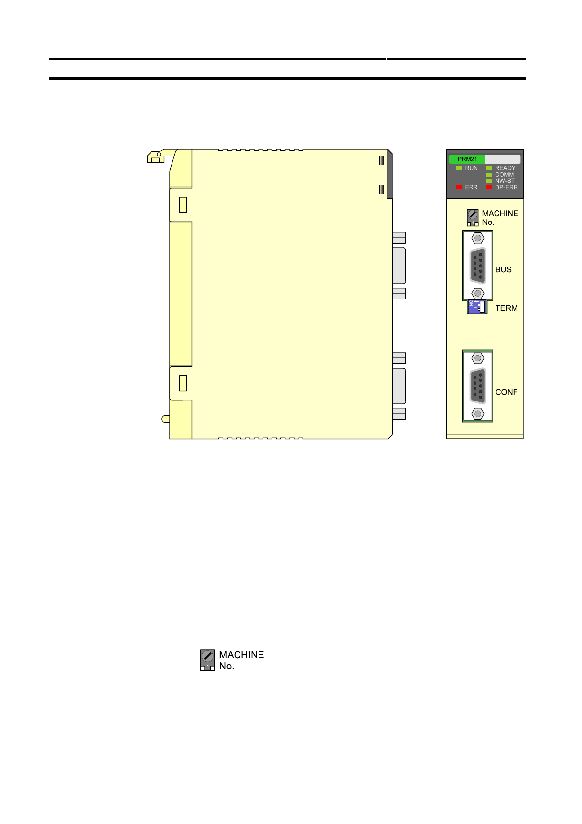
The figure below shows the side and front views of the C200HW-PRM21.
Section 2-1
2-1-1 LEDs
2-1-2 Rotary Switch
The front view shows the indicator LEDs, the ‘Machine No.’ rotary switch, two
9-pin female sub-D connectors, and the bus termination switch.
The C200HW-PRM21 has 6 indicator LEDs. The two LEDs on the left side
give a status indication of the unit in general. The four LEDs on the right side
are related to the status of the PROFIBUS-DP network Refer to section 5-4
for a detailed (functional) description of the LEDs.
The rotary switch is used to set the unit number (or so called “Machine No.”).
The unit number setting determines which words in the Internal Relay and
Data Memory Areas are allocated to the Master Unit.
The allowed unit number setting range depends on the PLC CPU Unit being
used, as shown in the following table.
10
Page 27
Physical layout of the unit
Section 2-1
Note
2-1-3 BUS Connector
CPU Unit models Unit number
C200HS, C200HE,
C200HG-CPU3[ ]-E/CPU4[ ]-E,
C200HX-CPU3[ ]-E/CPU4[ ]-E
C200HG-CPU5[ ]-E/CPU6[ ]-E,
C200HX-CPU5[ ] -E/CPU6[ ]-E
Cs1-series
setting range
0 to 9 Single-digit
0 to F
Setting
method
hexadecimal
Any unit number in the setting range is allowed as long as it has not been set
on another Special I/O Unit connected to the PLC. If the same unit number is
used for the C200HW-PRM21 and another Special I/O Unit, an I/O Unit Over
error will occur in the PLC and it will not be possible to start up the
PROFIBUS-DP Network.
Always turn OFF the power to the PLC before changing the unit number
setting. The Unit only reads the unit number setting during the initialisation
after power-up, so not after a software reset.
Use a small flat-blade screwdriver to turn the rotary switch; be careful not to
damage the switch.
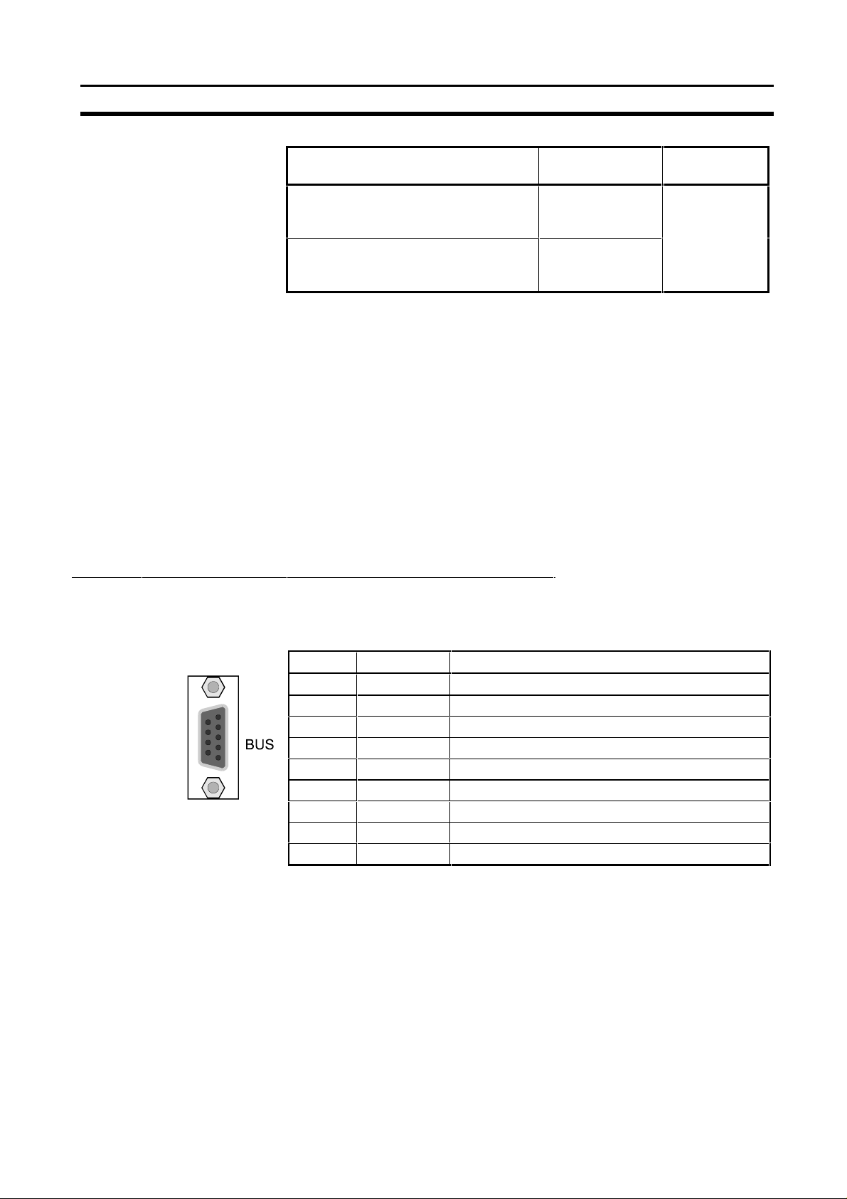
The fieldbus connector is a 9-pin female sub-D connector, as recommended
by the PROFIBUS standard EN 50170.
Pin No. Signal Description
1 Shield Shield / protective ground
2 - 3 B-line Data signal
4 RTS Control signal for repeaters (direction control) (TTL)
5 DGND Data ground
6 VP Supply voltage of the terminator resistance (5V)
7 - 8 A-line Data signal
9 - -
The signals DGND and VP are used internally to power the bus terminator
(see section 2-1-5).
The signal RTS (TTL signal) is meant for the direction control of repeaters if
repeaters without self control capability are used.
The PROFIBUS standard defines 24 V remote powering signals for pin 2 and
pin 7. These signals are optional and have not been implemented in this Unit.
11
Page 28
Physical layout of the unit
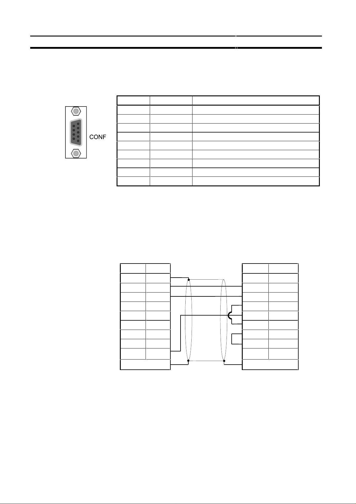
2-1-4 Configurator Connector
The configurator connector is a 9-pin female sub-D connector.
Pin No. Signal Description
1 FG Frame Ground (shield)
2 SD Send Data
3 RD Receive Data
4 RS Request to Send
5 CS Clear to Send
6 - 7 - 8 - 9 SG Signal Ground
The pin assignment of this connector is the same as the that of the RS-232C
port provided on most C200H-series CPUs. This enables the use of the same
serial communication cable for both the CPU and the C200HW-PRM21.
Section 2-1
The wiring of the RS-232C cable is shown in the picture below.
PRM21
Personal computer
Configurator port
Signal Pin No. Pin No. Signal
FG 1
shielded cable
1 SD 2 2 RD
RD 3 3 SD
RS 4 4 DTR
CS 5 5 SG
- 6 6 DSR
- 7 7 RS
- 8 8 CS
SG 9 9 -
Case Case
12
Page 29

Mounting the C200HW-PRM21
2-1-5 Termination Switch
The termination switch has two positions. When the switch is set to the right
(as shown below), the termination is disabled. By setting the switch to the left,
the termination is enabled.
Enabling the termination connects the two data lines using a 220 Ω resistor
which is connected to VP and DGND via two 390 Ω resistors (see figure
below). The powering of the terminator resistor ensures a defined idle state
potential on the data lines.
To ensure proper functioning up to the highest baud rate, the bus cable has to
be terminated on both ends of the cable.
VP
Section 2-2
390 Ω
B-line
220 Ω
A-line
390 Ω
DGND
2-2 Mounting the C200HW-PRM21
The PROFIBUS-DP Master Unit (C200HW-PRM21) can be mounted to the
CPU Rack or Expansion I/O Rack of any CS1, C200HX, -HG, -HE, or -HS
PLC. Refer to the PLC’s Installation Guide for details on mounting Units.
Limitations
There are some limitations on mounting the Master Unit.
• The Master Unit is a Special I/O Unit. It can be mounted in any slot in the
Backplane of a CPU Rack or Expansion I/O Rack as long as its unit
number is not the same as the unit number of another Special I/O Unit
within the system.
• The current consumption all of units mounted on one backplane should not
exceed the maximum output of the power supply. The C200HW-PRM21
consumes up to 600 mA from the 5V supply. Verify the characteristics of
all other units on their respective Instruction Sheets.
• The maximum number of Master Units that can be mounted depends on
the PLC CPU type.
13
Page 30

Setting up a network
C200HS-CPU[ ] (all models)
C200HE-CPU11/32/42
C200HG-CPU33/43
C200HX-CPU34/44
C200HG-CPU53/63
C200HX-CPU54/64
CS1-series
2-3 Setting up a network
2-3-1 Fieldbus cabling
Section 2-3
CPU Unit models Max. No. of Master Units
10
16
Bus structure
Cable type
Maximum length
All devices are connected in a bus structure (i.e. line). Up to 32 stations
(master or slaves) can be connected in one segment. The bus must be
terminated at the beginning and at the end of each segment. When more than
32 stations are used, repeaters must be used to link the individual bus
segments. The maximum number of stations that can be connected to a
C200HW-PRM21 is 124.
The standard EN 50170 specifies to use line type A of shielded twisted pair
cables with the following parameters:
Parameter Value
Impedance 135 to 165 Ω
Capacitance per unit length < 30 pF/m
Loop resistance 110 Ω/km
Core diameter 0.64 mm
Core cross section > 0.34 mm
2
The maximum length of the cable depends on the transmission speed. The
cable lengths specified in the table below are based on line type A.
Baud rate (kbit/s) Distance/segment (m)
9.6, 19.2, 93.75 1200
187.5 1000
500 400
1500 200
3000, 6000, 12000 100
Repeaters
Stub lines
14
The communication distance can be increased by the use of repeaters. It is
not recommended to use more than 3 repeaters in series. A repeater also
must be included in the count of the number of stations per segment to
determine the bus load (so only 31 ‘normal’ devices are possible per segment
if a repeater is used)
Stub lines should be avoided for data transmission speeds of more than
500 kbit/s. Plug connectors available on the market permit the incoming data
cable and the outgoing data cable to be connected directly in the plug
connector. This means that stub lines do not have to be used, and the bus
plug connector can be connected and disconnected at all times without
interrupting data communication with the other stations.
Page 31

Setting up a network
AAB
B
3
8
indu
c
tors
Section 2-3
Fieldbus connector
to next
station
The connector plug to be used on the C200HW-PRM21 is a 9-pin male subD, preferably with a metal case, and a facility to connect the shield of the
cable to the case. The cable should at least be connected to pin 3 (B-line) and
pin 8 (A-line) of the connector.
At baud rates of 1.5 Mbit/s or higher, always use special PROFIBUS-DP
plugs with built-in series inductances, to ensure that cable reflections caused
by the capacitive the load of each unit are minimised.
Connector plugs with built-in inductors, as shown here schematically, are
available from various manufacturers.
A standard 9-pin sub-D plug can only be used if the C200HW-PRM21 is at
the start or at the end of a bus segment, or on a stub line at baud rates of 500
kbit/s or less.
To ensure electro-magnetic compatibility (EMC), the shield of the cable
should be connected to the metal case of the connector. If this is impossible,
use pin 1.
If the Unit is installed within a control cabinet, the cable shield of the bus cable
should be electrically connected to a grounding rail as close as possible to the
cable lead-through using a shield grounding clamp or similar. The cable shield
should continue within the cabinet to the fieldbus device.
Ensure that the PLC and the control cabinet in which the device is mounted
have the same ground potential by providing a large-area metallic contact to
ground (use e.g. galvanised steel to ensure a good connection). Grounding
rails should not be attached to painted surfaces.
outside
cabinet
ground rail
You may find further information about
• Commissioning of PROFIBUS equipment
• Testing the PROFIBUS cable and bus connectors
• Determining the loop resistance
• Testing for correct bus termination
• Determining the segment length and cable route
• Other test methods
• Example of an equipment report
in the PROFIBUS guideline "Installation Guideline for PROFIBUS-DP/FMS"
(PNO Order No- 2.112), which is available at every regional PROFIBUS user
organisation.
15
Page 32

Setting up a network
2-3-2 Configuring the fieldbus
After making the physical connections of the network, the network needs to
be configured. For each master and its assigned slaves, a configuration has
Configurator
to be defined using SyCon, a dedicated PC-based configuration program.
The configurator provides the master with information about:
• The slaves that are connected to the master.
• The assignment of slaves to groups for broadcast / multicast messages.
• The mapping of the slaves into the memory of the master.
• The bus parameters (e.g. baud rate, target rotation time etc.).
For more details about the configurator refer to section 4.
Section 2-3
Downloading configuration
After entering the configuration, it must be downloaded to the master unit. A
serial COM-port of the PC is to be connected to the C200HW-PRM21 via the
prescribed RS-232C cable.
16
Page 33

3 Specifications and Performance
This section describes the overall specifications and the communication performance of the Unit
3-1 Overall Specifications..............................................................................................................................................18
3-2 Performance.............................................................................................................................................................20
3-2-1 Fieldbus cycle time.........................................................................................................................................20
3-2-2 PLC cycle time................................................................................................................................................24
3-2-3 I/O response time in asynchronous mode.......................................................................................................25
3-2-4 I/O response time in synchronous mode.........................................................................................................27
17
Page 34

Overall Specifications
3-1 Overall Specifications
Model code
Maximum. number of Master
Units
(with user defined I/O mapping)
Master Unit mounting position
Settings
Displays
External connectors
No. of IR words
No. of DM settings
No. of slave status words
Remote I/O
communications
Message communications
PROFIBUS-DP Baud rate
Network configuration
Current consumption
Storage temperature
Operating temperature
Operating humidity
Conformance to EMC- and
environmental standards
Weight
Max. No. of
Slaves per
Master Unit
Max. No. of I/O
words per
Master Unit
Supported
functions
CPU Rack or Expansion I/O Rack (classified as Special I/O Unit)
Unit cannot be mounted to SYSMAC BUS Slave Racks.
Unit cannot be used on a C200H PLC system.
Rotary switch : Unit number
Toggle switch : Bus termination
Unit status : RUN (green LED), ERR (red LED)
Network status : READY (green LED), COMM (green LED),
9-pin female sub-D connector (fieldbus connector, RS-485)
9-pin female sub-D connector (configurator connector, RS-232C)
2 words of control data out + 3 words of unit status in
18 words of unit setup information
16 words of status + diagnostic bits (location is user definable)
With default DM settings:
32 words in, 32 words out
With user defined DM settings:
80 words, in up to 4 areas
Not supported via IOWR / IORD instructions
as client : Data_Exchange, Slave_Diag, Set_Prm, Chk_Cfg, Global_Control
as server : Get_Master_Diag
Configurator program (SyCon V.1.5x) for WIN 3.x, WIN 95 and WIN NT
Section 3-1
C200HS C200HE/HG/HX, CS1
C200HW-PRM21
C200HE-CPU11/32/42
10
NW-ST (green LED), DP-ERR (red LED)
9.6 / 19.2 / 93.75 / 187.5 / 500 kbit/s,
1.5 / 3 / 6 / 12 Mbit/s
600 mA at 5 V DC (from PLC power supply)
-20 to +75°C
10% to 90% (non-condensing)
EN 50081-2
EN 61131-2
C200HG-CPU33/43
C200HX-CPU34/44
C200HG-CPU53/63
C200HX-CPU54/64
CS1-series
124
With default DM settings:
50 words in, 50 words out
With user defined DM settings:
300 words in up to 4 areas;
maximum 100 words per area
0 to +55°C
250 g
10
16
18
Page 35

Overall Specifications
Section 3-1
Dimensions
The following diagram shows the dimensions of the Master Unit. Refer to the
PLC’s Installation Guide for the dimensions of the Unit when it is mounted to
the Backplane. (All dimensions are in mm.)
19
Page 36

Performance
3-2 Performance
3-2-1 Fieldbus cycle time
This section gives a simplified method of fieldbus cycle time calculations.
Refer to EN 50170 for a more detailed calculation of the fieldbus cycle time.
The fieldbus cycle time with only one master is approximately:
Section 3-2
tBC = (ns + nr) x tMC + t
GAP_REQ
+ t
TC
where: ns = number of slave stations
nr = number of message retry cycles
tMC = message cycle time
t
= live list check time
GAP_REQ
tTC = token cycle time
The calculation of the fieldbus cycle time for multiple master networks is more
complex. For simplicity, extra time needed by each additional master can be
said to equal the time it holds the token and passes the token to the next
station, plus the time to check for live stations. In this case the fieldbus cycle
is approximately:
tBC = (ns + nr) x tMC + nm x (t
GAP_REQ
+ tTC)
where: ns = number of slave stations
nr = number of message retry cycles
tMC = message cycle time
nm = number of master stations
t
= live list check time
GAP_REQ
t
TC
= token cycle time
20
For each master station it is possible to specify the target rotation time using
the configurator software. If the actual fieldbus cycle time is less than the
target rotation time, all messages will be transmitted. If not, the master
stations will retain the low priority messages and transmit them at the next or
the following token receptions.
Note The fieldbus cycle time depends on many variables, not only those
mentioned in the formulas above. Therefore the formulas above only
give an approximation of the fieldbus cycle time.
The minimum possible fieldbus cycle time equals approximately 1 ms
(even if the formula gives a lower value).
The message cycle time, the live list check time, and the token cycle time are
explained below.
Page 37

Performance
Section 3-2
Message cycle time
A message consists of an action frame (request or send/request frame) and a
reply frame (acknowledge or response frame). The message cycle time is
composed of the frame transmission times, the transmission delay times, the
station delay time and the bus idle time.
TMC = t
ACTION-FRAME
+ t
REPLY-FRAME
+ 2 x t
TRANSMIT_DELAY
+ t
STATION-DELAY
+ t
IDLE
The station delay time is the time the slave needs for decoding the request
and generating an acknowledge or response frame.
The bus idle time is the time between an acknowledgement or response of
the slave and a new request from the master. Part of this time is used for
synchronisation (t
SYN
= 33 t
).
BIT
PROFIBUS has different formats for the action frame and the reply frame.
The frames can have a fixed format (with no data field or with a data field of 8
octets) or a variable format (with a variable data field length).
A general formula for the message cycle time:
tMC = (9+n1) x 11 + (9+n2) x 11 + 2 x 0 + 30 + 37 t
= (265 + 11n) t
BIT
BIT
where: n1 = number of action data bytes
n2 = number of reply data bytes
n = n1 + n2
The formula is based upon the following assumptions:
• The action frame and response frame have a variable format.
• The transmission delay times are negligible.
• t
• t
STATION-DELAY
IDLE
= 37 t
= 30 t
BIT
(typical value for the ASIC SPC3)
BIT
Live list check time
Each bus cycle the master requests the FDL (Fieldbus Data Link) status of
one of the stations connected to the network, except for the master stations
that have been entered in the LAS (List of Active Stations). The stations are
checked in sequence.
Each master is designated a certain range of slaves that it has to check. This
range is determined by the station addresses of the masters connected to the
network and the value for the parameter HSA (Highest Station Address).
A master checks the station addresses one higher than his own address up to
the next master address. If there is no master with a higher address, the
master checks until the value of HSA and starts again with checking from
station address 0.
If the station that is being checked is present and functions correctly, the
check time is approximately:
t
GAP_REQ
= t
REQ_FRAME
= 6 x 11 + 6 x 11 + 2 x 0 + 30 + 37 t
= 200 t
+ t
RES_FRAME
BIT
+ 2 x t
TRANSMIT_DELAY
BIT
+ t
STATION-DELAY
+ t
IDLE
21
Page 38

Performance
Section 3-2
If the station is not present, the master stops waiting for an answer after the
slot-time (one of the bus parameters). The check time in this case is:
t
= t
GAP_REQ
REQ_FRAME
= 6 x 11 + 100 + 37 t
= 203 t
The formulas are based upon the following assumptions:
• The transmission delay times are negligible.
• t
• t
• t
STATION-DELAY
IDLE
SLOT
= 37 t
= 100 t
= 30 t
BIT
BIT
(configurable)
BIT
Token cycle time
The token cycle time is the time each master station requires to process and
transfer the token. It is composed of the token frame time, the transmission
delay time and the bus idle time.
+ t
+ t
SLOT
IDLE
BIT
BIT
(typical value for the ASIC SPC3)
tTC = t
TOKEN-FRAME
+ t
TRANSMIT_DELAY
+ t
IDLE
The bus idle time contains the station delay time of the receiver and the
synchronisation time.
A general formula for the token cycle time:
tTC = 3 x 11 + 0 + 37 t
= 70 t
BIT
BIT
The formula is based upon the following assumptions:
• The transmission delay time is negligible.
• t
= 37 t
IDLE
BIT
Examples
The two figures below give an indication of the fieldbus cycle time. In each
figure the bus cycle time is calculated for four different baud rates (500 kbit/s,
1500 kbit/s, 3000 kbit/s, and 12000 kbit/s).
The first figure shows the effect of the number of slaves on the bus cycle time.
The values of the parameters are:
n = 4 (number of data bytes per slave)
ns = variable on the x-axis
nr = 0
Baud rate = variable per curve
The fieldbus cycle time is calculated with the formula for a single master
system.
The bus cycle time increases when the number of slaves increases due to the
fact that the total number of data bytes that needs to be transferred increases.
22
Page 39

Performance
Bus cycle time vs number of slaves
Baud rate
kbit/s
Section 3-2
25.0
20.0
15.0
10.0
Bus cycle time [ms]
5.0
0.0
0 4 8 12 16 20 24 28 32
500
1500
3000
12000
Slaves
The second figure shows the effect of the number of masters on the bus cycle
time. The values of the parameters are:
n = 4
ns = nm (each master has one slave)
nm = variable on the x-axis
nr = 0
Baud rate = variable per curve
Bus cycle time vs number of masters
40.0
35.0
30.0
25.0
20.0
15.0
10.0
Bus cycle time [ms]
5.0
0.0
0 4 8 12 16 20 24 28 32
500
1500
3000
12000
Masters
This figure is resembles the first figure. An increase of the number of masters
also increases the number of slaves and thus increases the number of data
bytes that needs to be transferred. The only difference is the addition of the
time to pass the token from one master to the other master and the total time
on checking the stations is increased. This is an addition of about 270 t
per
additional master.
23
Page 40

Performance
3-2-2 PLC cycle time
Section 3-2
The PLC cycle time mainly depends on the size of the PLC program and the
I/O refresh time of the units.
The size of the PLC program is application specific. Besides optimising the
PLC program, the program execution time can only be decreased by using a
faster CPU.
The total I/O refresh time depends on the types of units that are mounted on
the Backplane(s). Not all units refresh the same amount of data.
The I/O refresh time of the C200HW-PRM21 depends on the number of data
areas and the number of I/O data words that have been mapped.
The I/O refresh time of the C200HW-PRM21 Unit can be calculated with the
following formulas.
C200HS:
t
= 1.6 + 0.4 x na + 0.067 x nw [ms]
IORF
C200HE, C200HG, C200HX, CS1:
t
= 1.0 + 0.4 x na + 0.018 x nw [ms]
IORF
where: na = number of mapped data areas
nw = number of mapped I/O words (na ≥ 1)
Note
Using the default mapping mode, the I/O refresh time is:
C200HS : 6.7 ms (2 areas: 32 words out, 32 words in)
C200HE,
C200HG,
C200HX,
CS1-series : 3.6 ms (2 areas: 50 words out, 50 words in)
Refer to the Operation Manual of the CPU for more detailed calculations of
the PLC cycle time.
The I/O refresh time is not constant over all PLC cycles. During an I/O
refresh, the unit can transfer I/O data, slave status information, and IR words
(control & status). IR data is always transferred. I/O data and slave status
data are only transferred under certain conditions:
Input data: Only when there is new input data available. The
situation that there is no new input data occurs when the
fieldbus cycle time is greater than the PLC cycle time or
when the communication is inhibited.
Output data: Always transferred after the Unit is initialised, except
during a download and in the synchronous mode when
the fieldbus cycle time is greater than the PLC cycle time.
Slave Status: Always transferred after the Unit is initialised.
24
Page 41

Performance
3-2-3 I/O response time in asynchronous mode
In asynchronous data transfer mode, the fieldbus cycle is not synchronised
with the PLC cycle; fieldbus cycles are triggered continuously, independent of
the PLC cycle.
Minimum I/O response time
The figure below shows the minimum I/O response time in asynchronous
mode. The figure shows the timing at the PLC, the timing at the Master Unit,
the timing at the slave input and the timing at the slave output.
Section 3-2
Conditions
tIN : The Input Slave’s ON (OFF) delay
t
: The Output Slave’s ON (OFF) delay
OUT
t
BC
t
RF
t
PE
: The fieldbus cycle time
: The I/O refresh time
: Program Execution time
The minimum response time can be achieved under the following conditions:
1. No other master is connected to the network. More masters will increase
the fieldbus cycle time due to the token rotation between masters.
2. User defined I/O data mapping. Only map the input and output data of the
configured slaves. This will minimise the number of words that needs to be
transferred per PLC cycle and therefore the I/O refresh time.
3. The fieldbus baud rate is set to the highest value allowed for the attached
slaves and the used cable length.
4. The IORF instruction can be used to further decrease processing time in
the PLC program.
The minimum I/O response time that can be achieved with C200HE, -HG or HX and the CS1-series is approximately
9 ms + tIN + t
OUT
25
Page 42

Performance
Section 3-2
Maximum I/O response time
The figure below shows the maximum I/O response time in asynchronous
mode. The figure shows the timing at the PLC, the timing at the Master Unit,
the timing at the slave input and the timing at the slave output.
tIN : The Input Slave’s ON (OFF) delay
t
: The Output Slave’s ON (OFF) delay
OUT
t
BC
t
PC
t
RF
t
PE
: The Fieldbus cycle time
: The Poll cycle time of the respective master
: The I/O refresh time
: The Program Execution time
The maximum response time can occur under the following conditions.
1. The slave in question is polled by the respective master at the beginning
of the poll cycle.
2. The Input data is available just after the master polled the respective
slave.
3. The Master Unit finished processing just after the I/O refresh. The Input
data is not transferred to the PLC until the next PLC cycle.
4. A fieldbus cycle just started before the end of the I/O refresh, the output
data is not transferred until the next fieldbus cycle.
The I/O response time in the case above is:
t
RESPONSE
= tIN + 2 x tBC + tPC + 2 x tRF + 2 x tPE + t
OUT
Note: With tPC is meant the time the master of the respective slave needs
to poll all slaves that have been assigned to this master.
26
Page 43

Performance
3-2-4 I/O response time in synchronous mode
In synchronous data transfer mode, the fieldbus cycle is triggered immediately
following the I/O refresh of the PLC. If the fieldbus cycle has not finished
before the start of the I/O refresh, the fieldbus cycle is not triggered until after
the next I/O refresh.
Minimum I/O response time
The figure below shows the minimum I/O response time in synchronous
mode. The figure shows the timing at the PLC, the timing at the Master Unit,
the timing at the slave input and the timing at the slave output.
Section 3-2
tIN : The Input Slave’s ON (OFF) delay
t
: The Output Slave’s ON (OFF) delay
OUT
t
BC
t
RF
t
PE
: The fieldbus cycle time
: The I/O refresh time
: Program Execution time
The minimum response time can be achieved under the following conditions:
1. No other master is connected to the network. More masters will increase
the fieldbus cycle time due to the token rotation between masters.
2. User defined I/O data mapping. Only map the input and output data of the
slave. This will minimise the number of words that needs to be transferred
per I/O refresh and therefore minimise the I/O refresh time.
3. PLC cycle time is greater than the fieldbus cycle time. In this case it is
guaranteed that one fieldbus can be triggered per PLC cycle.
4. The fieldbus baud rate is set to the highest value allowed for the attached
slaves and used cable length.
5. The IORF instruction can be used to further decrease processing time in
the PLC program.
The minimum I/O response time that can be achieved with C200HE, -HG or HX and the CS1-series is approximately
8 ms + tIN + t
OUT
27
Page 44

Performance
Section 3-2
Maximum I/O response time
The figure below shows the maximum I/O response time in synchronous
mode. The figure shows the timing at the PLC, the timing at the Master Unit,
the timing at the slave input and the timing at the slave output.
tIN : The Input Slave’s ON (OFF) delay
t
: The Output Slave’s ON (OFF) delay
OUT
t
PC
t
RF
t
PE
: The Poll cycle time of the respective master
: The I/O refresh time
: The Program Execution time
The maximum response time can occur under the following conditions.
1. The slave in question is polled by the respective master at the beginning of
the poll cycle.
2. The poll cycle time of the respective master is less than the program
execution time of the PLC program.
3. The Input data is available just after the master polled the respective
slave.
The I/O response time in the case above is:
t
RESPONSE
= tIN + 3 x tPE + 3 x tRF + t
OUT
Note: With tPC is meant the time that the master of the respective slave
needs to poll all slaves that have been assigned to this master.
28
Page 45

4 Configurator
This section describes the configuration software package, required to set up a PROFIBUS-DP network
4-1 General...................................................................................................................................................................30
4-1-1Introduction ....................................................................................................................................................30
4-1-2System Requirements ......................................................................................................................................30
4-2 Setup ......................................................................................................................................................................31
4-2-1Installation......................................................................................................................................................31
4-2-2Uninstall .........................................................................................................................................................31
4-3 Operation................................................................................................................................................................32
4-3-1PROFIBUS-DP configuration ........................................................................................................................33
4-3-2Device database..............................................................................................................................................33
4-3-3Bus configuration............................................................................................................................................34
4-3-4Device configuration.......................................................................................................................................36
4-3-5Group membership .........................................................................................................................................39
4-3-6Check I/O assignments....................................................................................................................................40
4-3-7Bus parameters ...............................................................................................................................................42
4-3-8Download........................................................................................................................................................44
4-4 Debug mode...........................................................................................................................................................46
4-4-1Master Diagnostics .........................................................................................................................................47
4-4-2Slave Diagnostics............................................................................................................................................48
4-4-3Extended diagnostics ......................................................................................................................................49
29
Page 46

General
rd
4-1 General
SyCon
4-1-1 Introduction
Section 4-1
To define the network topology and PROFIBUS-DP system characteristics,
the C200HW-PRM21 needs to be provided with information about the slave
units connected to the network, and basic communication parameters.
This information is entered in the Unit by means of the configuration software
package SyCon (V.1.5 or higher). It is not possible to use other (generalpurpose) PROFIBUS-DP configuration software packages available from 3
parties.
The configuration software package for the C200HW-PRM21 PROFIBUS-DP
master is used to define:
• The configuration of the bus system connected to the C200HW-PRM21.
• Configuration- and parameter data of all connected slave stations.
• Overall bus communication settings.
All configuration data can be prepared offline. A serial communication link
with the C200HW-PRM21 is only necessary to download the configuration file
to the Unit, and for debugging purposes.
After the initial configuration has been downloaded, the software package can
be used for:
• Addition / deletion of slave units or -modules.
• Monitoring the PROFIBUS system status.
• Troubleshooting communication problems.
It is not possible to set up the C200HW-PRM21 without this configuration
software. Once the configuration data has been downloaded into the Unit, the
software package is no longer required during normal operation.
4-1-2 System Requirements
The following are the minimum requirements for a PC to install the
PROFIBUS-DP configurator SyCon V2.620.
Processor: 486DX50 or higher
Operating System: Windows 95/98
RAM: 16 MB or more
Hard disk space: 10 MB minimum
Graphics: 800x600x256 minimum
Serial port: RS-232C; COM1 to COM4 supported
Communication cable see 2-3-1 Fieldbus cabling
Windows NT 3.51
Windows NT 4.0
30
Page 47

Setup
4-2 Setup
4-2-1 Installation
Section 4-2
The PROFIBUS-DP configurator SyCon V2.620 is supplied on CD-ROM.
For installation instructions, see the file README.TXT on the CD-ROM.
For installation under Windows NT, administrator rights are required.
Since SyCon V2.620 serves as PROFIBUS-DP configurator for Master
devices of several manufacturers, it is necessary to make the correct choices
during installation to provide the correct settings for the C200HW-PRM21:
4-2-2 Uninstall
The license code is will be provided on the next installation screen.
When prompted, select to install the PROFIBUS component as well as the
CIF device driver.
SyCon V2.620 can be removed from your system by:
• selecting ‘SyCon Uninstall’ from the start menu, or
• through ‘Add/remove Programs’ in Control Panel.
31
Page 48

Operation
4-3 Operation
Section 4-3
Menu
File
Edit
View
Insert
Online
Settings
The operation of the configurator is menu-driven.
The functions located under the main menu items are:
• Create, load and save PROFIBUS-DP configuration files.
• Print configuration data.
• Copy GSD files to the device database folder.
• Exit the configurator.
• Delete items from the configuration.
• List all configured devices, sorted by address or by memory allocation.
• Add Masters and Slaves to the configuration
• Download the configuration to the Unit.
• Enter the online debug mode.
• Monitor the status of the network.
• Select serial communication port.
• Set overall bus system and communication parameters.
• Define group assignments for global control commands.
• Enter general project information.
• Select the display language (English, French, German)
Tools
Window
Help
• View the main data of PROFIBUS-DP GSD files.
• Arrange and select all open configuration windows.
• Access the help files
• Display version information.
32
Page 49

Operation
!
Caution
4-3-1 PROFIBUS-DP configuration
To build a PROFIBUS-DP configuration in a reliable and efficient way, adhere
to the following sequence of actions:
1, 2, 3...
1. Copy the GSD files of all stations into the assigned folder.
2. Define the master unit, and assign a bus address to it.
3. Define the bus configuration by adding stations to the bus, assigning
addresses to the stations, and configuring each device as required.
4. Define the assignment of each slave’s in- and output data to the internal
buffers of the Unit (or use the master’s auto-addressing function).
5. Configure the parameters of all slaves and slave modules as required.
6. Define the overall system- and communication bus parameters.
7. Save the configuration file to disk.
8. Select the serial communication port (Device Assignment)
9. Download the configuration into the Master Unit.
10. Select debug mode to verify the correct operation of the network.
4-3-2 Device database
Section 4-3
GSD files
Images
Languages
Device Database Folder
Each PROFIBUS-DP device, master or slave, is characterised by its Device
Database file, also known as GSD file (from German ‘Geräte StammDaten’).
The GSD file contains information about a device’s functionality and
characteristics, which need to be known during the configuration of a
PROFIBUS-DP network.
The GSD file for the C200HW-PRM21 is named OC_1656.GSD, and is
provided with the configurator software package (see also Appendix B). For
each slave that needs to be configured, a specific GSD file must be provided
by the manufacturer of the device. Without the GSD file, a slave cannot be
configured.
The GSD files may refer to bitmap files (*.DIB, 70x40 pixels x 16 colours)
which can be used by the configurator to display the status of the device. If
not found, a default image will be displayed.
GSD files may be available from the slave device manufacturer in several
languages. The file extension indicates the language used for module type
names, parameter options and diagnostic messages:
*.GSD = Default
*.GSE = English *.GSF = French
*.GSG = German *.GSI = Italian
*.GSP = Portuguese *.GSS = Spanish
All GSD files to be used in a project need to be available in a specific folder.
By default this folder will be:
<install path>\HMS\SyCon\Fieldbus\Profibus\GSD
It is possible to change the location via the menu item ‘Settings – Path…’.
GSD files can be added to the folder,
• through the menu item ‘File – Copy GSD’. SyCon will update its internal
device database automatically.
• by regular Windows file copy functions. SyCon needs to be (re-)started
after copying the GSD files into the assigned folder, in order to update its
device database.
Make sure that all GSD files are available in the assigned folder before
opening an existing configuration file.
33
Page 50

Operation
4-3-3 Bus configuration
Section 4-3
Master selection
The first step to build a configure a Master Unit is to open a blank sheet
through the menu item ‘File – New’, or the icon
.
Add the Master unit to be configured using ‘Insert – Master’ or the icon
Position the cursor to a line on the blank sheet, preferably at the top left, and
click to insert a Master Unit. A list of masters whose GSD files are found in
the Device Database folder is shown.
Select the C200HW-PRM21 from the list of available masters, and click the
‘Add>>’ button:
Multiple Masters
Selecting the added Unit from the list ‘Selected Masters’ allows you to set its
bus address before clicking ‘OK’.
It is possible to add multiple masters to a PROFIBUS-DP configuration.
However, each slave can only exchange data with a specific master, and
data exchange between masters is not possible.
The presence of multiple masters in one system will however affect the
overall bus parameter settings, and building a single configuration will help to
keep overview over which slave addresses are assigned to which master.
If multiple masters are defined in one configuration, always pay attention as to
which master subsequently inserted slaves are being assigned. Modifying the
assignment of slaves in a later stage may affect the mapping of other slaves’
I/O data to the Master’s I/O buffers.
34
Page 51

Operation
Section 4-3
Slave selection
After assigning the Master, the corresponding slaves can be added.
To add a slave, select ‘Insert – Slave’, or click the icon:
and select a row in the configuration window. If a unit is already on the
selected row, a new row will be inserted above it. The method of insertion is
the same as for master units. Multiple slaves can be inserted at a time.
Address sequence
Station addresses may be assigned in any sequence, and do not need to be
consecutive. The sequence displayed on the screen does not have to
represent the physical bus layout.
35
Page 52

Operation
4-3-4 Device configuration
Device configuration comprises the following steps:
1, 2, 3...
- Station address assignment.
- Slave module configuration.
- Mapping of the slaves’ I/O data to the Unit’s buffer areas.
- Setting the slaves’ User Parameter Data.
Section 4-3
Auto-addressing
Address assignment
Slave Configuration
The configurator offers the option to automatically assign the I/O data of each
slave to a location in the Unit’s buffer areas. This feature is turned ON by
default, and can be turned OFF via the menu item ‘Settings – Master
Configuration’ (select the Master Unit first), or by double-clicking the Master
Unit.
Station addresses will be assigned automatically according to sequence of
entry. Any automatically assigned address can be changed manually in the
Slave Configuration panel.
To configure a slave, select ‘Settings – Slave Configuration’, or double-click
on its icon in the PROFIBUS-DP window to bring up the following dialog box:
36
The station address can be changed by typing over the existing one, and
each slave can be assigned a symbolic name in the ‘Description’ field..
The check-box ‘Activate device…’ can be unchecked if the slave is not yet
available in the network, but address space needs to be reserved to add it
later.
When the ‘Enable watchdog control’ item is checked, the slave will perform a
specific action when bus communication is disrupted (depends on available
functionality in the slave, e.g. output hold, output clear). The actual watchdog
time is specified in the bus parameters. It is recommended to keep this
function enabled.
Page 53

Operation
Section 4-3
From the Slave Configuration panel, all other slaves can be accessed by
selecting them from the ‘Actual slave’ drop-down box.
The items ‘DPV1 Settings’, ‘Predefined Modules’ and ‘Symbolic Names’ are
not applicable to the C200HW-PRM21.
I/O configuration
Auto-addressing
I/O data allocation
If a predefined I/O configuration is made in the GSD file, this will be entered in
the module list automatically, and no further modules can be added.
In case of user-configurable modular slaves, select the required modules from
the list, either by double clicking, or using the buttons ’Append Module’ or
‘Insert Module’.
For further configuration of the slave, a button provides access to the
parameter data entry panel.
When Auto-addressing is enabled (through Settings – Master Configuration),
no further configuration of the I/O data assignment is required. The allocation
of the slave’s I/O data to the Master’s I/O buffers will be made automatically
before downloading the configuration to the Unit, or when viewing the address
table.
When Auto-addressing is disabled, the user must make sure that each slave
is allocated a sufficiently large area of the Unit’s buffers. When a slave’s I/O
data is found to be overlapping with another slave, an error message will be
generated when attempting to download. It is allowed to create gaps in the
slave’s allocations to the buffers, to anticipate an extension of the network in a
later stage. This will however result in a less than optimal data transfer
between the Unit and the PLC CPU.
The ‘Type’ indicator of each module denotes the slave module’s data format:
IB for byte inputs QB for byte outputs
IW for word inputs QW for word outputs
and the lengths of each module’s input and output data are listed under the
headings ‘I Len.’ and ‘O Len.’, respectively.
The locations of each modules’ I/O data in the buffers of the Master Unit can
be adapted by the user, specifying an offset in Words under ‘I Addr.’ and ‘O
Addr.’.
Manually entered offset assignments are automatically checked before being
downloaded into the C200HW-PRM21. See 4-3-8, ‘Download’.
The example below shows:
• One module (Slot=1) which has two indexed sub-modules (Idx=1, Idx=2)
• Submodule 1-1 has:
1 input word, starting at word 11 of the input buffer
1 output word, starting at word 9 of the output buffer
• Submodule 1-2 has:
16 input bytes, starting at word 12 of the input buffer
4 output bytes, starting at word 10 of the output buffer
37
Page 54

Operation
Section 4-3
Slave Parameter Data
Depending on the type of slave, specific parameter information may need to
be transferred to the slave at initialisation. The ‘Parameter Data’ dialog box
allows verification and adjustment of these parameters in several ways.
The initial dialog shows all parameter data in hexadecimal notation. A
thorough understanding of the device is required to modify the parameters
through this panel in a safe way. When in doubt, leave these values at the
defaults, which SyCon reads from the GSD file.
If the GSD file provides additional information for parameter adjustment, the
buttons ‘Common’ and/or ‘Module’ will be accessible.
‘Common’ provides access to the parameters which control the slave as a
whole, i.e. which are not specific for a module.
‘Module’ will allow the parameters for a specific module to be adjusted, e.g.
38
In the example shown, all German texts have been read from the device’s
GSD file. Please check with the slave manufacturer for the availability of files
in other languages.
All module assignments and parameter settings will be saved in the
configuration file, and need to be downloaded to the Master Unit. After the
download the Master will restart the network, and transfer the settings to the
slaves. The configuration and parameter settings cannot be changed online,
while the master is in data exchange mode.
Page 55

Operation
4-3-5 Group membership
Section 4-3
Group Definitions
Via the menu item ‘Settings – Group membership’, up to 8 groups of slaves
can be defined as targets for PROFIBUS-DP Global Control Commands.
The Group Membership dialog box allows definition of group names, and of
supported functions (Freeze / Sync) per group, For more information on the
execution of Freeze / Sync functions, see 5-3-1, Control words’.
Group names can be modified for easier identification. This has no effect on
the operation of the unit.
The ‘Freeze’ and ‘Sync’ check-boxes can be used to prevent assignment of
slaves which do not support these functions. Unchecking a function for a
specific group will not prevent the processing of the global control command
for that group.
Group Assignment
The ‘Group Assignment’ button provides access to the ‘Group Assignment’
dialog box, in which slaves can be assigned to the groups. Each slave may be
assigned to any number of groups. If a slave does not support SYNC and/or
FREEZE functions, assignment to a group with this function is not possible.
39
Page 56

Operation
4-3-6 Check I/O assignments
After the slaves have been configured, it is possible to obtain an overview of
all configured devices and their data allocation in the I/O buffers, by the menu
items ‘View – Device table’ and ‘View – Address table’.
Device table
The Device table shows all configured slaves, in the order in which they were
defined. This order is particularly important for the auto-addressing function:
offsets in the I/O buffer will be assigned to slaves in the order in which they
are presented in this device list. Slave addresses can be assigned and
redefined in any sequence, and do not influence the automatic addressing
function.
Section 4-3
Address table
The address table shows the start address and data length of each slave or
slave module in the Master’s input and output buffers.
The data location (‘I Addr.’, ‘O Addr.’) is always given as an offset in Words,
relative to the start of the buffer.
The ‘Type’ indication of each slave (module) shows if it concerns input (I) or
output (Q) data, and if the data is byte (B) or word (W) oriented. This type
determines also if the shown length (‘I Len’, ‘O Len’) is in Bytes or in Words.
If auto-addressing is enabled, the address list is recalculated each time it is
accessed.
The address table has two sorting methods:
1. Sort according to station address. This sorting method is most convenient
to find the location of a particular slave (module) in the I/O buffers.
40
Sorted by station address.
Page 57

Operation
Section 4-3
2. Sort according to data address. This sorting method is most convenient to
find which slave’s data is available at a given buffer location.
Sorted by data address.
The allocation of each Byte of each module can be checked by clicking the
button ‘Address Overview…’.
By double-clicking an individual byte, it is possible to check from which
module in which slave unit the data originates.
41
Page 58

Operation
!
Caution
4-3-7 Bus parameters
Section 4-3
The menu item ‘Settings – Bus parameters’ leads to a dialog box where the
overall PROFIBUS-DP communication parameters can be set. In most cases,
only the baud rate will need to be set to the required value. This can be done
in the following panel:
The configurator will verify that the selected baud rate is supported by all
devices connected to the master, and issue a warning if this is not the case.
‘Optimize = standard’ will automatically adjust all bus parameter settings to a
value derived from the data found in the slaves’ GSD files, and the selected
baud rate. These values can be viewed by clicking the ‘Edit…’ button.
Only in extreme cases it may be required to adjust these settings, i.e. with
exceptionally large configurations (>80 slaves), or when using a large number
of repeaters or signal converters.
For manual adjustment of bus parameters, select ‘Optimize = by user’ and
click ‘Edit…’.
It is highly recommended to access the bus parameter panel after all slaves
have been configured. By changing the baud rate, all timing parameters will
be optimised for the number and types of defined slaves. If the configuration
is subsequently modified, select the chosen baud rate again to re-activate the
parameter optimisation. If any bus parameter is modified manually, no
automatic recalculation will take place until the baud rate is changed.
Baud rate Sets the communication speed for the master and all
slaves which support auto baud rate detection. All
standardised PROFIBUS-DP values from 9.6 kbit/s to 12
Mbit/s are supported by the C200HW-PRM21. A change
of baud rate will recalculate all parameters to a value
optimised for the actual configuration at the new baud
rate.
42
Page 59

Operation
Section 4-3
Slot Time (TSL) The maximum time the Master must wait for a transaction
response.
Station Delay of
Responders (T
Quiet Time (T
Setup Time (T
SDR
) The time a transmitting station must wait after the end of
QUI
SET
Target Rotation
Time (TTR)
GAP Actualisation
Factor
The minimum and maximum allowed times for a slave to
)
generate a reply frame.
a frame before enabling its receiver.
) The time between an event and the necessary reaction.
The anticipated time for one token cycle, including
allowances for high and low priority transactions, errors
and GAP maintenance (set in bit times, value in ms is
calculated). Do not decrease T
below the suggested
value, otherwise bus communication may get interrupted.
GAP is defined as the range between this master and its
successor in the logical token ring (i.e. in case more than
one active station operates on the same bus).
The master will periodically check if new active stations
have been added between address 0 and the Highest
Station Address (see below). If stations are detected,
GAP is updated.
The factor defines the checking period in multiples of the
Target Rotation Time (TTR). Allowed values are 1 to 255.
Max. Retry Limit Maximum number of retries by this master, if a station
does not properly respond to a request.
Highest Station
Address (HSA)
Defines the maximum range of addresses in which this
master periodically searches for newly added active
stations. If multiple masters are to operate on the same
bus, set HSA at least equal to the highest master
address.
Poll Timeout The maximum time interval that this master station may
need for the execution of a master-master function
(respond to a DPM2 request).
Data Control Time The cycle time in which this master updates its Data
Transfer List in which it keeps an overview of all slave
states, and indicates its operation mode to the associated
DP slaves.
Data Control Time is automatically set to the
recommended value of 6*TWD.
43
Page 60

Operation
!
Caution
Section 4-3
Min. Slave Interval The smallest allowed period of time between two slave
poll cycles. This value is determined by the largest value
of all Minimum Slave Interval values as read from the
GSD files of the configured slaves. This ensures that all
slaves can handle the sequences of requests they
receive from this master.
4-3-8 Download
No Upload
When to download
Watchdog Control
Time (TWD)
Auto_clear Mode
OFF/ON
The PROFIBUS-DP configuration, defined offline, needs to be downloaded
into the C200HW-PRM21. Please note that uploading the configuration data
from the unit is not possible, since detailed information concerning slaves and
modules will not be saved in the Unit. Therefore it is advised to save your
configuration on disk before starting a download.
There are two situations in which a configuration download is allowed.
The first situation is when on startup, the Unit has detected that a corrupted
database is present in its non-volatile memory. In this case the RUN LED is
flashing and the DP-ERR LED is ON. As soon as the download is started, the
DP-ERR LED goes OFF and the READY LED will flash. When the download
is successful and a valid database is detected, the initialisation of the unit will
continue.
The second situation is after initialisation is completed. This is when the RUN
LED is ON. During the download, the READY LED will flash and the other
PROFIBUS-related LEDs will be OFF. After completion of the download, the
received database is checked. If the database is valid, the Unit is re-initialised;
and the READY LED is turned ON. If the database is invalid, the DP-ERR
LED will be ON and the user needs to re-execute the download.
If a slave’s watchdog is enabled, and it does not detect
master activity for a period T
fail-safe state. T
slaves, based on the value of TTR.
Determines if the master will change from Operate to
Clear mode if it detects that one or more configured
slaves are not in data exchange mode.
If Auto_clear mode is ON, a single slave failure will thus
reset the outputs of all active slaves.
is automatically set for all configured
, it will set its outputs to a
Note
Device Assignment
44
Do not start a download in another situation than described above. The
download will most likely fail, requiring a restart of the Unit.
Before a download, make sure a serial port of the PC is connected to the
CONF port of the Unit using a cable as specified in 2-1-4, ’Configurator
Connector’.
Make sure the cursor is on the targeted Master station, then select the menu
item ‘Settings – Device Assignment’. Click the ‘Connect COMx’ buttons to test
the connection to the Master unit. If the test succeeds, version information will
be displayed as shown.
If multiple masters are connected to various COM ports, make sure the
correct check box is selected.
Page 61

Operation
Section 4-3
Download
Slave overlap
Upon selecting ‘Online – Download’, the software will verify if the device
assignment has been made. If necessary, the user will be prompted to select
a serial port.
If the download is started, the C200HW-PRM21 will stop all communication
on PROFIBUS-DP until the download is completed.
Before actually starting the download, the configurator will first perform a
number of checks on the entered configuration data.
If any slave data is found to overlap with another slave or module, the
download is aborted. An error message is displayed to indicate the first
allocation problem that was encountered, e.g.:
Use the address table viewer to locate the problem, and resolve the conflict
by modifying the offset of one or more slaves.
When auto-addressing mode is selected, all slave offsets are recalculated
before a download, and no allocation conflicts should occur. The calculated
offsets can be verified in the address list.
If all checks have passed successfully, a progress indicator is displayed:
Downloading the configuration data will take several seconds, depending on
the size of the configuration. After the download, the C200HW-PRM21 will
restart. If the unit does not respond correctly, the download will be aborted.
45
Page 62

Debug mode
!
WARNING
4-4 Debug mode
Configuration file
Section 4-4
The C200HW-PRM21 configurator software SyCon allows the user to inspect
the status of the unit and the assigned slaves online via the CONF port of the
Master Unit.
In order to reliably display the status of the PROFIBUS-DP network, the
correct configuration file must be open in the configurator. Immediately after a
download this is automatically the case; if the unit has to be accessed for
debugging in a later stage, the user must make sure that the correct file is
opened before activating the debug function. The configuration file cannot be
uploaded from the unit.
The debug function can be started via the menu command ‘Online – Start
Debug Mode’.
Functions
The Debugger provides the following functions:
• Display of master unit status.
• Display of PROFIBUS-DP network state.
• Display of each slave’s state,
including slave diagnostics (standard + extended).
The following Online functions are not supported by the C200HW-PRM21:
• Firmware download
• Firmware / Reset
• I/O Monitor
• Start Communication
• Stop Communication
• Device Info
• Activate Driver
Execution of the ‘Firmware download’ and ‘Firmware/Reset’ functions may
lead to permanent corruption of the firmware of the C200HW-PRM21.
‘Start/Stop Communication’ should be performed using the ‘I/O Communication Inhibit’ bit in the PLC (see 5-3-1 Control words).
‘I/O Monitor’, ‘Device Info’ and ‘Activate Driver’ will cause no damage or
corruption of data, but will display incorrect information.
46
Page 63

Debug mode
4-4-1 Master Diagnostics
Section 4-4
Master Status
The state of the PROFIBUS-DP Master can be monitored through the menu
item ‘Online – Global State Field’, or while in debug mode, by double-clicking
on the Master unit’s icon, and selecting ‘Global State Field’ from the list
shown below, and clicking ‘Display’:
Please note that not all items from the Task State list are supported by the
C200HW-PRM21. Invalid data may be displayed in some of the views.
The ‘Global Task State’ window shows the status of the Master Unit and its
slaves. For a detailed explanation of the data shown, please refer to the Help
files of SyCon (Press F1).
‘Online master main state’ indicates the same as the upper 2 bits of status
word IR n+2, i.e.:
C0 = OPERATE
80 = CLEAR
40 = STOP
00 = OFFLINE
47
Page 64

Debug mode
4-4-2 Slave Diagnostics
Section 4-4
Slave Status
In debug mode, the bus configuration display shows a status overview of all
configured devices:
Slave Diagnostic
The station’s status is indicated by the colour of connection to the main bus
line, and by the displayed image of the device.
Green Normal data exchange with this slave.
Red Slave has diagnostic information or the master couldn't find this
slave on the bus, i.e. there is no data exchange with this slave.
• A thin, black connecting line (e.g. Slave 4) indicates that the slave is not
assigned to the selected master unit. The status of this slave cannot be
monitored.
• A cross through the slave icon (e.g. Slave 3) indicates that the slave was
defined to be not active in the current configuration (See 4-3-4 Device
configuration).
A double click with the mouse on a slave device calls up more detailed
diagnostic information. Slave diagnostics are displayed as defined in the
PROFIBUS-DP standard EN 50170.
Diagnostic information in this window is not updated online. Close and reopen
the window to refresh the information.
For a detailed explanation of the displayed information, consult the online
Help system (press F1).
48
Page 65

Debug mode
Section 4-4
If the flag ’Extended Diag’ is set, the slave has additional diagnostic
information, and the button ’Ext Diagnostic’ will be available. Extended
diagnostics will be displayed in a separate window.
4-4-3 Extended diagnostics
The displayed extended diagnostic texts are dependent on the information
provided in the device’s GSD file. SyCon translates the diagnostic message
as received from the slave in hexadecimal format (bottom window) into the
texts as specified in the GSD file. Different language versions of the GSD file
may be available from the manufacturer.
If multiple messages are available, they can be selected for display using the
scroll bar on the right.
The meaning of the displayed messages is slave dependent, and should be
described in the slave’s documentation.
49
Page 66

Debug mode
Section 4-4
50
Page 67

5 PLC Interface
This section describes the interface with the user via the PLC system. This includes Unit settings to configure
the Unit and the control / status area.
5-1 Unit Settings.............................................................................................................................................................52
5-1-1 I/O Data Mapping..........................................................................................................................................52
5-1-2 Slave Status Area Mapping ............................................................................................................................57
5-1-3 Data Exchange Method..................................................................................................................................57
5-1-4 Fatal PLC error handling ..............................................................................................................................58
5-2 Input / Output Mailbox.............................................................................................................................................59
5-3 Control and status area.............................................................................................................................................60
5-3-1 Control words.................................................................................................................................................61
5-3-2 Status words ...................................................................................................................................................64
5-4 LEDs........................................................................................................................................................................70
51
Page 68

Unit Settings
5-1 Unit Settings
Section 5-1
This Special I/O Unit is configurable with settings made in a dedicated DM
area. The assigned DM area depends on the Unit number setting.
Unit
number
0
1
2
3
4
5
6
7
8
9
A
B
C
D
E
F
* Alternatively starting at DM7000 ~ DM8500, selected by PLC setup of C200H..:
DM6602 ≠ 0000 (see Operation Manual of CPU unit)
DM area*
DM1000 ~ DM1017
DM1100 ~ DM1117
DM1200 ~ DM1217
DM1300 ~ DM1317
DM1400 ~ DM1417 All PLC models
DM1500 ~ DM1517
DM1600 ~ DM1617
DM1700 ~ DM1717
DM1800 ~ DM1817
DM1900 ~ DM1179
DM2000 ~ DM2017
DM2100 ~ DM2117 All PLC models except:
DM2200 ~ DM2217 C200HS, C200HE,
DM2300 ~ DM2317 C200HG-CPU3[ ]-E/CPU4[ ]-E,
DM2400 ~ DM2417 C200HX-CPU3[ ]-E/CPU4[ ]-E
DM2500 ~ DM2517
The first word in the DM area allocated to the unit will be indicated by DM m,
the last word by DM m+17.
The Unit settings determine the areas and methods for data exchange
between the PLC CPU and the C200HW-PRM21.
Data entered in the Unit settings area is only transferred to the unit during
initialisation, i.e. at power ON and at Special I/O Unit restart.
Note
The Unit operates in default mode when all Unit settings are set to zero.
5-1-1 I/O Data Mapping
Data flow
I/O refresh
52
The figure below shows the flow of remote I/O data in the PLC system. It is
possible to map the I/O data to the DM, LR, IR and HR areas of the PLC
memory. Up to two input areas and two output areas may be assigned.
Output data is transferred via the bus on the Backplane (I/O Bus) to the
output buffer of the Unit. At certain time intervals this data is transmitted to the
slaves over PROFIBUS. Slave input data coming from PROFIBUS is first
stored in the input buffer of the Unit. At certain times, this data is transferred
to the memory of the PLC. The exchange of data via the I/O Bus occurs
during an I/O refresh.
By default, I/O refreshes are executed at the end of each PLC program cycle,
but can also be triggered by the IORF instruction.
Page 69

Unit Settings
Section 5-1
User configurable
Maximum I/O data
Data representation
The mapping of the PROFIBUS-DP slaves onto the buffers of the Unit is
defined with the configurator described in section 4. The mapping between
the I/O data buffers of the Unit and the PLC memory is user configurable via
the settings in data memory.
For C200HS, the maximum number of mapped I/O data is 80 words and for
C200HE, C200HG, C200HX and CS1-series, the maximum is set to 300
words. If the user-defined mapping exceeds these values, the mapping is
ignored (no data will be exchanged) and a fatal error is indicated in IR n+2
(see section 5-3) and the ERR LED is turned ON.
The maximum amount of data mapped per single transfer block is 100 words.
In the I/O data buffers, the high bytes of PLC data always occupy even
addresses, the low bytes occupy odd addresses (Motorola format).
The representation of PROFIBUS-DP slave data in the I/O data buffer
depends on the specifications of the slave. Please consult the slave
manufacturers’ documentation. In rare cases it may be necessary to modify
the data representation either at the slave side, or in the PLC program.
53
Page 70

Unit Settings
Setting values in BCD
Section 5-1
The table below lists the DM words for configuring the I/O data mapping, with
the possible values and their meaning.
Except for the definition of the start address in the PLC CPU, all values are in
BCD. To be able to distinguish between start addresses in different PLC
memory areas, the first digit of the ‘start address’ indicates the PLC memory
area, the following three digits indicate the address in the PLC memory area
in BCD format.
Words vs. Bytes
CS1-series
Note that data allocation in the PLC memory is in WORD units, whereas the
allocation in the Unit’s buffers is in BYTE units (1 word = 2 bytes). The start
address in an I/O data buffer area must always be even. Odd-valued entries
will generate a setting error.
For details on I/O data mapping on CS1-series PLC’s, see Appendix C.
DM word Value Meaning
m
m+1
m+2
m+3
m+4 see m+1
m+5 see m+2
m+6 see m+3
Number of output data areas
0000 Default mapping
C200HS:
PLC addresses IR050 ~ IR081 are mapped to
Unit output buffer bytes 000 ~ 063
C200HE,C200HG,C200HX:
PLC addresses IR050 ~ IR099 are mapped to
Unit output buffer bytes 000 ~ 099
0001 One user-defined data output area
0002 Two user-defined data output areas
other Default mapping (see value 0000)
Output area 1 : start address in the output buffer
0000 ~ 0510 Byte 000 ~ 510 (even) in output buffer of the Unit
other Setting error *1, output area is ignored
Output area 1 : start address in the CPU
0000 ~ 4095 DM0000 ~ DM4095 (C200HE-CPU11)
0000 ~ 5999 DM0000 ~ DM5999 (all other CPUs)
A000 ~ A235 IR000 ~ IR235
A300 ~ A511 IR300 ~ IR511
B000 ~ B099 HR00 ~ HR99
C000 ~ C063 LR00 ~ LR63
other Setting error *1, output area is ignored
Output area 1 : size
0000 ~ 0100 0000 ~ 0100 words to be transferred from PLC to
Unit output buffer *
other Setting error *1, output area is ignored
Output area 2 : start address in the output buffer
Output area 2 : start address in the CPU
Output area 2 : size
2
continued →
54
Page 71

Unit Settings
Section 5-1
DM word Value Meaning
m+7
m+8
m+9
m+10
m+11 see m+8
m+12 see m+9
m+13 see m+10
*1 Setting errors are indicated in IR n+2 (see section 5-3) and the ERR LED will
be flashing to indicate a non-fatal error.
*2 If the specified number of words would make the area exceed the boundaries of
the available buffer, DM, LR, IR or HR areas, the actual number of transferred
words will be limited as to remain within all of these boundaries. This setting
error is indicated in IR n+2 (see section 5-3) and the ERR LED will be flashing
to indicate a non-fatal error.
Number of input data areas
0000 Default mapping
C200HS:
Unit input buffer bytes 000 ~ 063 are mapped to
PLC addresses IR350 ~ IR381
C200HE,C200HG,C200HX:
Unit input buffer bytes 000 ~ 099 are mapped to
PLC addresses IR350 ~ IR399
0001 One user-defined data input area
0002 Two user-defined data input areas
other Default mapping (see value 0000)
Input area 1 : start address in the input buffer
0000 ~ 0510 Byte 000 ~ 510 (even) in input buffer of the Unit
other Setting error *1, input area is ignored
Input area 1 : start address in the CPU
0000 ~ 4095 DM0000 ~ DM4095 (C200HE-CPU11)
0000 ~ 5999 DM0000 ~ DM5999 (all other CPUs)
A000 ~ A235 IR000 ~ IR235
A300 ~ A511 IR300 ~ IR511
B000 ~ B099 HR00 ~ HR99
C000 ~ C063 LR00 ~ LR63
other Setting error *1, input area is ignored
Input area 1 : size
0000 ~ 0100 000 ~ 100 words to be transferred from Unit input
buffer to PLC *
other Setting error *1, input area is ignored
Input area 2 : start address in the input buffer
Input area 2 : start address in the CPU
Input area 2 : size
2
Notes
• The Unit does not check the validity of the contents of any PLC data area,
from which output data is to be transferred. Any data present in the area
will be transferred to the output buffer of the Unit.
• If multiple fieldbus masters (e.g. PROFIBUS-DP, CompoBus/D, SYSMAC
BUS) are mounted on the same PLC system, only one of them can be
used in default mapping mode. The Unit does not check if the mapped
PLC input area is in use by other Units. If so, this Unit’s data may
overwrite another Unit’s data, or vice versa.
• If the settings cause two destination areas to overlap, the data of the
higher number area will overwrite the lower. This practice is to be avoided
by the user.
55
Page 72

Unit Settings
Section 5-1
Example I/O data mapping
Below is an example of user-defined I/O data mapping. The unit number is
set to 0, so the settings start at DM word 1000. The example defines two
output areas and one input area.
DM word Value Meaning
1000 0002 Two output areas
1001 0000 Write to output buffer of Unit starting at address 000
1002 B050 Read data from PLC starting at HR50
1003 0020 Transfer 20 words of output data
1004 0520 Write to output buffer of Unit starting at address 520
1005 C000 Read data from PLC starting at LR00
1006 0050 Transfer 50 words of output data
1007 0001 One input area
1008 0400 Read data from input buffer of Unit starting at address 400
1009 A500 Write data to PLC starting at address IR500
1010 0100 Transfer 100 words of input data
1011 any No 2nd input area
1012 any No 2nd input area
1013 any No 2nd input area
The first output area is correctly defined, all values are in range.
The second output area has an incorrect value for the start address in the
output buffer of the Unit (520 > 510). This output area will not be mapped; the
output data will not be transferred to the buffer. This setting error is indicated
in IR n+2 (see section 5-3) and the ERR LED will be flashing.
Also the input area definition causes a setting error. The specified number of
words to be transferred crosses the boundaries of both the available IR area
and the input buffer area. The available input buffer area is 112 bytes (400 ~
511) and the available IR area is 12 words (IR500~IR511). The number of
input words that will be transferred is therefore limited to 12 words = 24 bytes
(the lesser of the two values). This is also a setting error which will be
indicated in IR n+2.
56
Page 73

Unit Settings
5-1-2 Slave Status Area Mapping
DM m+14 and DM m+15 define the PLC data area where the 16 words of
slave status information are to be mapped. By default (i.e. both settings are 0)
the Unit uses IR200 ~ IR215, an IR area originally reserved for SYSMAC BUS
slaves. Therefore, if the Unit is used in combination with a SYSMAC BUS
remote master unit, the default mode should not be used.
DM word Value Meaning
m+14
m+15
Slave status data mapping mode
0001 User defined mapping defined by DM m+15
other Default mapping to IR200 ~ IR215
Start address in user-defined mapping mode
(Area size = 16 words)
0000 ~ 4080 DM0000 ~ DM4080 (C200HE-CPU11)
0000 ~ 5984 DM0000 ~ DM5984 (all other CPUs)
A000 ~ A220 IR000 ~ IR220
A300 ~ A496 IR300 ~ IR496
B000 ~ B084 HR00 ~ HR84
C000 ~ C048 LR00 ~ LR48
other Default mapping to IR200 ~ IR215
Section 5-1
The user is to verify that the assigned area is not yet allocated to other Units.
5-1-3 Data Exchange Method
DM m+16 defines the data exchange procedure between the Unit and the
PLC. The two possible exchange methods are:
1. Asynchronous: the fieldbus cycles are triggered independently of the PLC
cycle and therefore the fieldbus cycles run asynchronous with the PLC
cycle. This method provides optimal I/O response time when the PLC
cycle time is at least twice the fieldbus cycle time.
2. Synchronous: The fieldbus cycles are triggered at the end of an I/O refresh
and therefore the fieldbus cycle is synchronised with the PLC cycle. If the
fieldbus cycle time is greater than the PLC program execution time, the
next fieldbus cycle will not be triggered until the completion of the next I/O
refresh. This method ensures synchronisation between PLC cycle and
fieldbus cycle.
These exchange methods are described in more detail in section 3-2.
DM word Value Meaning
m+16
Data exchange procedure
0000 Default, fieldbus cycle asynchronous with PLC cycle
other Fieldbus cycle synchronous with PLC cycle
Note
In synchronous mode, with the slave watchdog enabled (configurable), the
PLC cycle time should be less than the set watchdog time (configurable)
otherwise the watchdog of the slave will expire. If the PLC cycle time can not
be reduced, the watchdog time of the slave must be set to a larger value, or
the asynchronous mode must be used.
57
Page 74

Unit Settings
!
Caution
5-1-4 Fatal PLC error handling
DM m+17 defines the handling of fatal PLC errors. The Unit will react on a
falling edge of Run bit IR n.00. The Run bit will turn OFF in case of:
• a fatal error in the PLC system, e.g. Memory error, I/O bus errors.
• a system FALS error.
• a user-generated FALS error.
• a PLC CPU mode change to/from Program mode.
If any of these situations occur, the remote outputs will be switched to a userdefined state. If the data exchange mode (selected with DM m+16) is
asynchronous, DM m+17 allows the user to choose between:
CLEAR outputs:
The output data in the Output buffer is cleared and transmitted to the slaves
(if communication is not inhibited).
HOLD outputs:
The output data in the Output buffer is not transmitted to the slaves anymore;
the outputs of the slaves remain the previous state.
DM word Value Meaning
m+17
Section 5-1
Fatal PLC error handling (asynchronous data exchange mode)
0000 CLEAR outputs
other HOLD outputs
Note
This selection is ONLY valid when the Unit operates in the asynchronous data
exchange mode (i.e. DM m+16 = 0000). Even if program execution stops,
fieldbus communication is maintained by the Unit, independent of the PLC
cycle.
In synchronous data exchange mode, when program execution stops, no
fieldbus cycles are triggered. Therefore the remote output status cannot be
maintained. The status of PROFIBUS-DP will automatically change to
CLEAR, followed by STOP. All outputs will be cleared automatically, even if
DM m+17 specifies to hold the outputs!
The Unit is not able to distinguish between a user-controlled reset of the IR
n.00 bit and a reset due to a fatal PLC error. Both are handled in the same
way. Be aware that changing the to/from Program mode will also reset IR
n.00. In Program mode, it is possible to force IR n.00 to the ON state, so that
remote I/O can be operated for debugging and commissioning.
58
Page 75

Input / Output Mailbox
5-2 Input / Output Mailbox
Section 5-2
PROFIBUS-DP specific
commands
Beside the input and output buffer, the Unit also contains an input mailbox
and an output mailbox. PROFIBUS-DP specific commands can be transferred
from the CPU to the output mailbox. The response to the command placed in
the output mailbox will be placed in the input mailbox. This response can then
be read by to the CPU.
There are two ways to transfer a command to the output mailbox.
1. Issuing a command by IOWR instruction in the PLC program. The
contents of the data area specified by the IOWR instruction are transferred
to the output mailbox.
2. Via the control words. The most common PROFIBUS-DP control
commands can be selected by activating the corresponding bit in the
control word IR n. The Unit will interpret this control word and place the
corresponding command in the output mailbox.
Responses to these common control commands are automatically removed
from the input mailbox. These responses contain no valuable information for
the user.
Responses to other commands - issued via IOWR instructions - should be
read from the input mailbox with the IORD instruction. If this is omitted, the
input mailbox buffer will fill up. When this is the case, the output mailbox will
be disabled; it will not be possible to transfer commands to the output mailbox
anymore. Once the input mailbox is emptied again, the outstanding
commands in the output mailbox will be processed by the unit.
Details about the IOWR and IORD instructions are given in section 6.
Note The input mailbox can also be cleared using control word IR n. The
status of the mailboxes is indicated in the status word IR n+2.
59
Page 76

Control and status area
5-3 Control and status area
After initialisation of the unit (RUN LED is ON), the control and status words
are exchanged between the PLC and the Unit during each I/O refresh. The
mapping of the control words and unit status words depends on the Machine
number set by the rotary switch at the front of the Unit.
Section 5-3
Unit
number
0
1
2
3
4
5
6
7
8
9
A
B
C
D
E
F
IR area
IR100 ~ IR104
IR110 ~ IR114
IR120 ~ IR124
IR130 ~ IR134
IR140 ~ IR144 All PLC models
IR150 ~ IR154
IR160 ~ IR164
IR170 ~ IR174
IR180 ~ IR184
IR190 ~ IR194
IR400 ~ IR404
IR410 ~ IR414 All PLC models except:
IR420 ~ IR424 C200HS, C200HE,
IR430 ~ IR434 C200HG-CPU3[ ]-E/CPU4[ ]-E,
IR440 ~ IR444 C200HX-CPU3[ ]-E/CPU4[ ]-E
IR450 ~ IR454
The first word in the IR area allocated to the Unit will be indicated by IR n, the
last word by IR n+4.
The first two words are control words and are sent to the Unit. The next three
words are status words and are read from the Unit.
The mapping of the slave status words that are read from the Unit is defined
by the Unit settings (see section 5-1-2).
Note
CS1-series
During a configuration download or when a fatal error occurs in the unit, the
control words IR n and IR n+1 will not be processed.
For details on the area allocation in CS1-series PLC’s, see Appendix C.
60
Page 77

Control and status area
5-3-1 Control words
IR n
Section 5-3
The two control words, IR n and IR n+1, are shown below.
Any bits of the control words which are not assigned to a specific function,
can freely be used as work bits. These bits will be ignored by the C200HWPRM21.
15 14 13 12 11 10 9 8 7 6 5 4 3 2 1 0
Run
I/O communication inhibit
Input mailbox clear
Issue control command
Clear_Data
Unfreeze
Freeze
Unsync
Sync
IR n+1
15 14 13 12 11 10 9 8 7 6 5 4 3 2 1 0
Station address
Group select
Group 1
Group 2
Group 3
Group 4
Group 5
Group 6
Group 7
Group 8
IR n.00 Run
0: No exchange of I/O data between PLC and remote I/O, and
no processing of mailbox commands will take place. A
transition from 1 to 0 will clear or hold the outputs depending
on the value set in DM m+17. Holding remote outputs is only
available in asynchronous data exchange mode.
1: Unit in normal operation; exchange of I/O data with PLC, and
processing of mailbox commands are enabled.
The purpose of this bit is to allow detection of a fatal PLC error. A
fatal PLC error will reset the whole IR area; the Unit monitors IR
n.00, and on a 1 → 0 transition it performs the action specified in
the Unit settings (see section 5-1-4).
Note: It is recommended to always set this bit ON during PLC
program execution. See also Appendix Appendix A.
61
Page 78

Control and status area
Section 5-3
IR n.01 I/O communication inhibit
0: I/O communication is enabled.
1: I/O communication is disabled. A transition from 0 to 1
changes the PROFIBUS-DP network state from ‘Operate’ via
‘Clear’ to ‘Stop’. All remote outputs will therefore be reset.
Data in the input buffer of the Unit will no longer be updated
and transferred to the PLC anymore (I/O refresh time will
decrease). The PLC’s output data however, is still transferred
to the output buffer of the Unit. This ensures that the output
buffer contains valid output data at the moment the communication is enabled again.
When I/O communication is disabled, the output mailbox is
disabled as well. It is possible to send mailbox commands to
the Unit, but they are not transferred to the output mailbox.
Because no commands are put in the output mailbox, no
responses will be received in the input mailbox.
IR n.02 Input mailbox clear
0: No specific action.
1: Each I/O refresh, one unprocessed response (if available) is
removed from the input mailbox.
IR n.03~06 Not used by C200HW-PRM21.
IR n.07 Issue control command
0: No control commands are issued.
1: Each I/O refresh, one control command is issued.
The control command is specified by IR n.09~13, and the
destination is specified by IR n+1. No control command is
transferred to the output mailbox if either the RUN-bit (IR
n.00) is not set or if the communication is inhibited (IR n.01) or
the output mailbox is not ready to receive a command due to a
full input mailbox. In the next PLC cycle, IR n+2.11 will
indicate whether the control command was accepted or not.
Each fieldbus cycle, only one control command will be
transmitted.
IR n.08 Not used by C200HW-PRM21.
IR n.09~13 Specification of the PROFIBUS-DP control command.
Bit Command Meaning
09 Clear_Data Clear output data
10 Unfreeze Unfreeze input data
62
11 Freeze Freeze input data
12 Unsync Unsynchronise output data
13 Sync Synchronise output data
When activated simultaneously, Unsync has priority over Sync,
Page 79

Control and status area
Multicast
Broadcast
and Unfreeze has priority over Freeze.
The Clear_Data command will always clear the output data,
whether the Freeze command is activated or not.
Note
The control commands ‘Freeze’ / ‘Sync’ are overruled by a reset
of the slave. The control command has to be issued again after
the reset to have the slave working in the desired mode.
IR n.14~15 Not used by C200HW-PRM21.
IR n+1 Group select and Station address
PROFIBUS-DP provides multi-peer communication (broadcast
and multicast).
To enable multicast communication, each slave can be assigned
to one or more groups (See 4-3-5, ‘Group membership’). Up to
eight groups can be defined (1~8). A target group for a multicast
command is selected by setting the corresponding bit in IR n+1.
A specific slave within a group is selected by specifying its
address in the Station address area (hexadecimal). When the
Station address value is set to 7Fh, all slaves assigned to the
group(s) are selected.
Entering the value 00h in the Group select area of IR n+1 selects
all groups. Therefore any single slave can be addressed by
entering 00h for Group select and the station address of the slave
for Station address. This also enables to address a slave that has
not been assigned to a certain group.
A broadcast command to all slaves is generated by entering the
values 00h for Group Select and 7Fh for Station Address.
Section 5-3
Example: The first table shows an example of the assignment of
the slaves to groups as made with the configurator.
Stations Group assignment
02h ~ 20h no group
21h ~ 40h group 1
41h ~ 60h group 2
61h ~ 80h group 1 and group 2
The second table shows some examples of settings
for Group select and Station address, and the
resulting selection of slaves that will be targeted by a
control command.
Group select Station address Selection
00h 15h slave 15h
01h 75h slave 75h
01h 15h 03h 7Fh slave 21h ~ 80h
00h 7Fh slave 02h ~ 80h
63
Page 80

Control and status area
Section 5-3
Sync / Freeze control
5-3-2 Status words
The purpose of the control commands Sync and Freeze is to be able to
synchronise the outputs and inputs of the slaves.
The data exchange between the master and slaves is based upon the polling
technique. This means that the exchange of data between the slave and the
master does not occur at the same time for all slaves.
The outputs of the slaves can be synchronised by issuing Sync commands.
This function is activated after the first Sync command is sent to the slaves.
After activation of this function, the output data sent by the Master does not
get through to the output. It is stored in a buffer. The data in the buffer is not
transferred to the output until another Sync command is issued. Multicasting a
Sync command results in a update of the outputs of all corresponding slaves
at the same time. This function can be disabled again by sending an Unsync
command.
The Freeze and Unfreeze command work in a similar way. They are meant
for synchronising the input data. After activating the function, by sending a
Freeze command, the input data is not updated until another Freeze
command is sent.
The Unit provides 19 words of status information.
Three words (IR n+2 ~ IR n+4) show the status of the Unit (system status)
and 16 additional words show the status of all slaves. System status
information is transferred in each I/O refresh, irrespective of the state of the
fieldbus system. The slave status information is also always transferred, but is
not valid when the PROFIBUS-DP bus communication does not function
properly or during the download of a configuration. In that case the slave
status information bits will be reset to 0.
IR n+2
System status
The three words that indicate the system status are shown below.
15 14 13 12 11 10 9 8 7 6 5 4 3 2 1 0
Input data transferred
Auto_clear
No_data
P-DP H/W failure
Wrong CPU Unit
DM setting error (exceeding max. words)
DM setting error (output area mapping)
DM setting error (input area mapping)
Control command not processed
Output mailbox full
Reply in input mailbox
Network state
64
Page 81

Control and status area
IR n+3
IR n+4
Section 5-3
15 14 13 12 11 10 9 8 7 6 5 4 3 2 1 0
Error number
Station address
15 14 13 12 11 10 9 8 7 6 5 4 3 2 1 0
Message length (001~128)
Unit number (0 ~ F)
IR n+2.00 Input data transferred
0: No input data has been transferred to the mapped PLC data
area(s) during the last I/O refresh.
1: Input data has been transferred to the mapped PLC data
area(s) during the last I/O refresh.
The Unit does not always transfer input data to the mapped
PLC data area(s). If the Unit cannot provide updated input
data during an I/O refresh, no data will be transferred. This will
typically occur if the fieldbus cycle time is larger than the PLC
cycle time, or if the DP communication has been inhibited.
IR n+2.01 Not used by C200HW-PRM21.
IR n+2.02 Auto_clear (PROFIBUS-DP status bit).
0: Not in Auto_clear mode. This bit is also cleared during a
database download or a P-DP H/W failure is detected (IR
n+2.06 is set).
1: The master branched into Auto_clear mode, because of a
remote node error.
The master will only branch into Auto_clear mode when this
has been enabled in the configuration (see 4-3-7, Bus
parameters). In Auto_clear mode, the network state bits
indicate Stop, and the DP-ERR LED is flashing. IR n+3 will
indicate more details about the cause of the error.
To recover from Auto_clear mode, the C200HW-PRM21 must
be restarted (Power OFF / ON or restart bit in AR01 / SR281).
IR n+2.03 No_data (PROFIBUS-DP status bit).
0: All remote nodes are in data exchange mode. This bit is also
cleared during a database download or when a P-DP H/W
failure is detected (IR n+2.06 is set).
1: At least one remote node is not in the data exchange mode or
reports a fatal error.
The DP-ERR LED is FLASHING to indicate this error. IR n+3
contains more details about the cause.
65
Page 82

Control and status area
Section 5-3
IR n+2.04
IR n+2.05
IR n+2.06 P-DP H/W failure
IR n+2.07 Wrong CPU Unit.
IR n+2.08 DM setting error (exceeding maximum number of words).
Not used by C200HW-PRM21.
0: No error
1: Malfunctioning of the PROFIBUS-DP hardware.
The ERR LED is ON to indicate a fatal error, no communication over PROFIBUS.
0: No error
1: The Unit is mounted to a PLC type which does not support the
C200HW-PRM21.
The ERR LED is ON to indicate a fatal error, no communica-
tion over PROFIBUS.
0: No error
1: The input/output area mapping, defined by the Unit’s DM
settings, exceeds the maximum allowed number of words
(300 words for all PLC’s, except C200HS: 80 words).
The ERR LED is ON to indicate a fatal error, no communication over PROFIBUS.
IR n+2.09 DM setting error (output area mapping)
0: No error
1: There is an error in the output area mapping.
The mapping contains an incorrect value for either:
- the start address in the output buffer in the Master,
- the start address of the output area(s) in the PLC,
- or the size of the output area(s),
or the specified size makes the area(s) exceed the boundaries
of available buffer, DM, LR, IR or HR areas.
The ERR LED is FLASHING to indicate a non-fatal error; no
data is transferred from the output area(s) afflicted by the
setting error(s).
IR n+2.10 DM setting error (input area mapping)
0: No error
1: There is an error in the input area mapping.
The DM settings contain an incorrect value for either:
- the start address in the input buffer in the Master,
- the start address of the input area(s) in the PLC,
- or the size of the input area(s),
or the specified size makes the area(s) exceed the boundaries
of available buffer, DM, LR, IR or HR areas.
The ERR LED is FLASHING to indicate a non-fatal error; no
data is transferred from the output area(s) afflicted by the
setting error(s).
66
Page 83

Control and status area
Section 5-3
IR n+2.11 Control command not processed.
This bit is related to control commands sent via the control words
IR n and IR n+1, not the one sent via IOWR instruction.
0: The output mailbox was able to receive and process the
previously issued control command message.
1: The issued control command could not be processed because
the output mailbox was full (see section 5-2) or the RUN-bit
was not set or the bus communication was inhibited.
This bit should be checked in the PLC cycle following the
activation of a control command.
IR n+2.12 Output mailbox full
0: The output mailbox is able to receive (and process) a
message. This message can be a control command issued via
IR n or any PROFIBUS command by using the IOWR
instruction.
1: The output mailbox is full and cannot receive new messages
(see section 5-2).
IR n+2.13 Reply in input mailbox
0: The input mailbox does not contain a response message to a
command message issued with IOWR.
1: The input mailbox contains a response message to a
command message issued with IOWR.
The PLC program should read this message from the input
mailbox with IORD, or clear the message by setting IR n.02. If
multiple command messages are issued without reading the
responses, the input mailbox will fill up, making it impossible to
send out further command messages (see section 5-2).
IR n+4 contains the source information for the IORD
instruction.
IR n+2.14
Network state (PROFIBUS-DP status bits).
IR n+2.15
IR n+2.15 IR n+2.14 Network state
0 0 Offline
0 1 Stop
1 0 Clear
1 1 Operate
Communication with all DP participants is
stopped.
Only communication with DP-Master
(class 2) is possible.
The master tries to set parameters, check
configuration and perform data exchange
with its associated DP-slaves; the slaves’
inputs are transferred to the input buffer,
their outputs are cleared.
The master exchanges data with the
assigned DP-slaves.
Note
The network state will be Offline when a P-DP H/W failure is detected
(IR n+2.06 is ON) or when a database download is in progress.
67
Page 84

Control and status area
Section 5-3
IR n+3
This IR word contains information about the PROFIBUS-DP error
status.
IR n+3 will indicate the error type and the station address of the
station that is in error. If more than one station is in error, it will
report on the first station that is detected to be in error. After
removing the cause of the error it will report on the next station
that was found in error. If the error is in the master itself, the
Station address will show the value FFh.
The following table lists the error types.
Station
address
any 00h
≠FFh 03h
FFh 36h
Error
number
11h
12h
38h
D4h
BE
other
Cause Action
No errors
Function in slave is
not activated
No response of the
slave
The Master is not
into the logical
token ring
Error in
configuration data
Bus errors detected Check the bus
Unit fault Try downloading the
Check if the slave is
conform PROFIBUS-DP
norm and that the correct
GSD files are used
Check the bus cable and
the station address of the
remote node
Check the node address
of the master and the
highest station address of
other master systems.
Check if the cables are
connected properly.
Download the
configuration again
connections and cabling.
configuration again; if the
same error occurs,
replace the Unit
68
Note
When the PROFIBUS hardware does not function properly (P-DP
H/W failure, IR n+2.06 bit is ON), the contents of this word is set
to 0.
IR n+4 Unit Number and Message Length
When IR n+2.13 is set (Reply in output mailbox), this IR word
contains the length of the message that can be retrieved with an
IORD instruction. Combined with the Unit number, this constitutes
the correct source information for the IORD instruction. Refer to
section 6-3 for more details about the IORD instruction.
Note
When the PROFIBUS hardware does not function properly (P-DP
H/W failure, IR n+2.06 bit is ON), the contents of this word is set
to 0.
Page 85

Control and status area
bit
word
0
1
2
3
4
5
111 110 109 108 107 106 105 104 103 102 101 100 99 98 97 96
6
7
8
9
10
11
12
13
111 110 109 108 107 106 105 104 103 102 101 100 99 98 97 96
14
15
Slave status
The 16 words that contain the slave status bits are shown below. The location
of these words in the PLC’s memory depends on the settings in DM m+14
and m+15 (see 5-1-2). Default location is IR 200 ~ 215.
These words only indicate the status of the slaves that have been assigned to
the respective master Unit and thus possibly not of all slaves in the network.
15 14 13 12 11 10 9 8 7 6 5 4 3 2 1 0
15 14 13 12 11 10 09 08 07 06 05 04 03 02 01
31 30 29 28 27 26 25 24 23 22 21 20 19 18 17 16
47 46 45 44 43 42 41 40 39 38 37 36 35 34 33 32
63 62 61 60 59 58 57 56 55 54 53 52 51 50 49 48
79 78 77 76 75 74 73 72 71 70 69 68 67 66 65 64
95 94 93 92 91 90 89 88 87 86 85 84 83 82 81 80
125 124 123 122 121 120 119 118 117 116 115 114 113 112
Section 5-3
Active flags stations 01 ~ 15
Active flags stations 16 ~ 31
Active flags stations 32 ~ 47
Active flags stations 48 ~ 63
Active flags stations 64 ~ 79
Active flags stations 80 ~ 95
Active flags stations 96 ~ 111
Active flags stations 112 ~ 125
Diagnostic flags stations 01 ~ 15
Diagnostic flags stations 16 ~ 31
Diagnostic flags stations 32 ~ 47
Diagnostic flags stations 48 ~ 63
Diagnostic flags stations 64 ~ 79
Diagnostic flags stations 80 ~ 95
Diagnostic flags stations 96 ~ 111
Diagnostic flags stations 112 ~ 125
Slave active bits
Slave diagnostic bits
Note
The first 8 words comprise the ‘slave active’ flags. These indicate which of the
slaves are active and are exchanging data with the master Unit. If a slave
active flag is OFF (0), the corresponding slave is either not configured, or not
exchanging data.
It is recommended to use the ‘slave active’ bit as a condition in the PLC
program for processing the slave’s input data. If the ‘slave active’ bit is OFF,
the presented input data may not be valid.
The next 8 words comprise the ‘slave diagnostic’ flags. These indicate if slave
diagnostic information is available from the corresponding slave station.
The master sets a flag when the diagnostic data sent by the slave does not
contain all zeros. Diagnostic data that only contains zeros is considered as no
diagnostics.
The diagnostic bit is also set when a configured slave fails to respond.
When the diagnostic bit is set, the corresponding diagnostic data can be
retrieved by sending a ‘request for diagnostics’ command to the output
mailbox with an IOWR instruction. The corresponding reply can be read from
the input mailbox with an IORD instruction (see section 6 for command
transfer by IOWR / IORD). The diagnostic bit is reset after the request, but if
the cause for diagnostics is persistent, the diagnostic bit will remain ON.
The contents of these status words are cleared during the initialisation after
start-up, during a download of a new configuration and when the PROFIBUS
hardware does not function properly (P-DP H/W failure, IR n+2.06 bit is set).
69
Page 86

LEDs
5-4 LEDs
Section 5-4
The Unit has six LEDs to visualise its status. The layout of the LEDs is shown
below.
The two LEDs on the left side (RUN, ERR) show the status of the Unit in
general. The four LEDs on the right side indicate the status of the
PROFIBUS-DP network.
The different states of the LED are listed in the table below. The following
flowchart describes the sequence in which the LEDs are turned ON or OFF.
In some states additional information is indicated by the status word IR n+2
and IR n+3. The flowchart and the table refer to this status word where
applicable.
Unit status LEDs
LED Colour State Description
RUN Green OFF Fatal error detected
Flashing Initialising the hardware / software
ON The Unit is initialised and no fatal error is
detected
ERR Red OFF No errors
Flashing Non-fatal error due to incorrect Unit settings
Details in IR n+2.09, n+2.10
ON Fatal error.
Details in IR n+2, bits 06 through 08
70
Page 87

LEDs
Section 5-4
PROFIBUS-DP status LEDs (only valid when RUN LED is ON)
LED Colour State Description
READY Green OFF PROFIBUS-DP fatal error
Flashing Configuration download in progress
IR n+2.14 and IR n+2.15 are OFF (Offline)
ON The Unit is ready to communicate.
COMM Green OFF The master does not get any positive reply
back from the slaves during the polling
procedure. No I/O data is being exchanged
with DP-slaves.
ON The master does get at least one positive reply
back from one of the slaves in the network.
This does not automatically mean that I/O data
is being exchanged!
NW-ST Green OFF Network state is Offline or Stop
IR n+2.14 = 0
Flashing Network state is Clear
IR n+2.14 = 1, IR n+2.15 = 0
ON Network state is Operate
IR n+2.14 = 1, IR n+2.15 = 1
DP-ERR Red OFF No PROFIBUS-DP specific errors and no fatal
PLC error detected.
Flashing At least one of the DP slaves is in error or is
not configured correctly (See also IR n+2.02,
n+2.03).
ON Configuration error is detected, RUN LED or
READY LED is flashing (see also IR n+3).
Download the configuration again.
71
Page 88

LEDs
Section 5-4
Power-up / Reset
Start
All LEDs off
RUN-LED
flashing
Wrong
configuration data
present?
Initialisation
finished?
N
N
Y
Y
Fatal error
detected?
RUN-LED On
Non-fatal error
detected?
N
N
Configuration is being
downloaded?
Initializing the hardware / software
N
N
Y
Y
Correct configuration
downloaded?
N
N
DP-ERR-LED
On
DP-ERR-LED
Off
Y
Y
DP-ERR-LED
Off
IR n+3 = FF36h / FF38h / FFD4h
IR n+2.06 and / or IR n+2.07 and/or IR n+2.08 is set
IR n+2.09 and / or IR n+2.10 is set
IR n+2.15 and IR n+2.14 are OFF
IR n+3 = FF36h / FF38h / FFD4h
READY-LED
Flashing,
Correct configuration
downloaded?
DP-ERR-LED
On
N
N
RUN-LED Off
Y
Y
ERR-LED On
All other LEDs Off
N
N
Y
Y
ERR-LED
Flashing
Y
Y
COMM-LED Off,
NW-ST-LED Off,
DP-ERR-LED Off
N
N
PROFIBUS-DP fatal
error detected?
N
N
READY-LED
On
Exchanging data
with DP slaves?
Y
Y
COMM-LED On
Network
state is Offline or
Stop?
N
N
Network state
is Clear?
N
N
Network state
is Operate?
At least one of the
DP slaves is in error or is not
configured correctly?
Y
Y
Y
Y
Y
Y
Y
Y
N
N
COMM-LED
Flashing
NW-ST-LED
NW-ST-LED
Flashing
NW-ST-LED
Y
Y
READY-LED Off,
COMM-LED Off,
NW-ST-LED Off,
DP-ERR-LED On
Off
On
DP-ERR-LED
Flashing
IR n+2.14 ~ IR n+2.15 = 0x
IR n+2.14 ~ IR n+2.15 = 10
IR n+2.14 ~ IR n+2.15 = 11
IR n+2.02 and/or IR n+2.03 is set
72
N
N
DP-ERR-LED
Off
Page 89

6 Message Communication, IOWR / IORD
This section describes the message communication. The PLC program instructions IOWR and IORD are used
to transfer the messages to and from the Unit.
6-1 Message communication..........................................................................................................................................74
6-2 IOWR.......................................................................................................................................................................74
6-3 IORD........................................................................................................................................................................76
6-4 Messages..................................................................................................................................................................77
6-4-1 Control command ...........................................................................................................................................78
6-4-2 Slave diagnostics............................................................................................................................................79
73
Page 90

Message communication
f the PLC data area that contains the
Combination of the Unit number of the Master Unit and the message
6-1 Message communication
Section 6-1
Mailboxes
Control words
IOWR
IORD
Note
6-2 IOWR
The Unit handles the message communication via the Input and Output
mailbox. These mailboxes are described in section 5-2.
The control words (see 5-3-1) can be used to send standard messages, i.e.
PROFIBUS control commands. The IOWR instruction can be used to send
any fieldbus-specific message. The advantage of this method is that the Unit
will be able to handle future upgrades of fieldbus message types.
The Input mailbox will contain responses to commands sent out via the
Output mailbox. The Unit will automatically remove responses to control
commands as they do not contain any valuable information. Responses to
other commands sent with the IOWR instruction, have to be read with an
IORD instruction to prevent filling up of the Input mailbox.
The transfer of messages via the control words is described in section 5-3-1.
This section will describe the transfer of messages via IOWR / IORD.
The transfer of messages with IOWR and IORD is only supported by the
C200HE, C200HG, C200HX and CS1 PLC’s, not by the C200HS.
The ladder symbols for IOWR are shown below.
IOWR (-) @IOWR (-)
C C
S S
D D
C
Control code
value: #0000
S
First source word
value: The address of the first word o
message to be transferred to the Output mailbox.
D
Destination information
value:
length (number of words in BCD).
Message length (001 ~ 128)
Unit number (0 ~ F)
74
Page 91

IOWR
Output mailbox full
EQ-flag
ER-flag
Section 6-2
The IOWR instruction should not be executed unconditionally. The Output
mailbox is not always able to receive and process a new message. Status bit
IR n+2.12 indicates the status of the Output mailbox at the moment of the last
I/O refresh (1 = Output mailbox full). It is good practice to only execute the
IOWR instruction when IR n+2.12 is not set. It should be noted that this IR bit
is only updated during the I/O refresh and thus the status of this bit is not valid
anymore after executing an IOWR instruction in the PLC program. Therefore
it is recommended not to execute the IOWR instruction more than once per
PLC cycle.
The EQ-flag in the PLC will indicate the result of execution of the IOWR
instruction. If this flag is set, the message was transferred successfully to the
Output mailbox. If this flag is not set, either the Output mailbox was full, or the
RUN-bit (IR n.00) was not set, or the DP communication was disabled (IR
n.01). In all cases the message was not transferred to the Output mailbox. It
is advised to always check the EQ-flag.
The ER-flag in the PLC will report on syntax errors made in the IOWR
instruction itself. It is not necessary to check this flag; if a syntax error is
made, the EQ-flag will also indicate that the transfer was not successful.
Example
An example of the use of the IOWR instruction is shown below.
IR 112.12
IOWR (-)
#0000
DM0000
#1008
255.06
EQ_FLAG ERROR
In the example above, the Unit number setting is assumed to be ‘1’.
The IOWR instruction is only executed when the ‘Output mailbox full’ bit is not
set. It transfers 8 words starting from DM0000 to the Output mailbox of the
Master Unit with Unit setting 1.
The ERROR output bit is set when the IOWR transfer was not successful.
75
Page 92

IORD
Combination of the unit number of the Master Unit and the message
IR n+4 can be used as source information. If a message is posted in
the input mailbox, this IR word will contain the correct information for
The address of the first word of the PLC data area to where the
6-3 IORD
The ladder symbols for IORD are shown below.
IORD (-) @IORD (-)
C C
S S
D D
C
Control code
value: #0000
S
Source information
value:
length (number of words in BCD).
retrieval of the full message.
Section 6-3
Reply in input mailbox
Input mailbox clear
EQ-flag
ER-flag
Message length (001 ~ 128)
Unit number (0 ~ F)
D
First destination word
value:
message from the Input mailbox is to be transferred.
The IORD instruction should not be executed unconditionally. IORD should
only be executed when there is a reply message in the Input mailbox. The
status of the Input mailbox is indicated by status bit IR n+2.13 (Reply in input
mailbox). If this bit is set, an IORD instruction should be executed to remove
the response from the Input mailbox. This will prevent the Input mailbox from
filling up.
An IORD instruction should not be executed in the PLC cycle after an ‘Input
mailbox clear’ command is issued. As the ‘Input mailbox clear’ command (IR
n.02) will not be executed until after the I/O refresh, the status of IR n+2.13
will be updated in the next I/O refresh.
It is not recommended to execute two IORD instructions per PLC cycle
because the status of IR n+2.13 is not valid anymore after executing the first
IORD instruction.
The EQ-flag in the PLC will indicate the result of execution of the IORD
instruction. If this flag is set, the message was transferred successfully from
the Input mailbox to the specified PLC data area. It is advised to always check
this flag, especially in the cases described above when an ‘Input mailbox
clear’ command has been issued, or when more than one IORD instruction is
programmed to be executed in one PLC cycle.
The ER-flag in the PLC will report on syntax errors made in the IORD
instruction itself. It is not necessary to check this flag; if a syntax error is
made, the EQ-flag will also indicate that the transfer was not successful.
76
Page 93

Messages
Section 6-4
Example
An example of the use of the IORD instruction is shown below.
IR 112.13
IORD (-)
#0000
114
DM0000
255.06
EQ_FLAG ERROR
In the example above the Unit number setting is assumed to be ‘1’.
The IORD instruction is only executed when the ‘Reply in input mailbox’ flag is
set. IR 114 contains the correct source information. The IORD instruction
transfers the oldest reply from the Input mailbox to the PLC, starting at
DM0000.
The ERROR output bit is set when the IORD transfer was not successful.
This could be because of a syntax error in the IORD instruction or because
there was no reply in the Input mailbox anymore.
6-4 Messages
Fixed format
Max. length
Command types
Messages to be sent to the Output mailbox and received from the Input
mailbox have a fixed format. The command and the response are according
the following format.
Type Size
(words)
Message header 4 Defines the sender, receiver, command type and
Telegram header 0 ~ 4 Detailed definition of the command message
Telegram data 0 ~ 124 Message data
Description
the total length of the telegram. It is also possible to
give a unique number to each message.
The overall length of the message is limited to 128 words (limitation of the
IOWR / IORD instruction). Every message has a message header, but not all
messages have a telegram header or telegram data. In messages without a
telegram header, the length of the telegram data can be up to 124 words.
With a telegram header, the length can only be up to 120 words.
The two types of command message presently supported are:
1. Control command
2. Slave diagnostics
These commands are described in more detail in the next two sub-sections.
77
Page 94

Messages
6-4-1 Control command
This command can also be issued via the control words (see section 5-3-1).
The message for a control command is shown below.
The message consists of 6 words which have to be prepared in a PLC data
area.
Station address and Group select are described in the paragraph on control
word IR n+1 (see section 5-3-1).
The settings in the Control command byte define which control command is to
be sent; see table below.
Section 6-4
MSB LSB
word n 03h 10h
word n+1 03h 00h
word n+2 00h 00h
word n+3 46h 00h
word n+4 Station address
(00h ~ 7Fh)
word n+5 Group select
(00h ~ FFh)
Control command
00h
Command priority
No response message
Bit Command Meaning
0 - 1 Clear_Data Clear output data
2 Unfreeze Unfreeze input data
3 Freeze Freeze input data
4 Unsync Unsynchronise output data
5 Sync Synchronise output data
6 - 7 - -
When issued simultaneously, Unsync has priority over Sync, and Unfreeze
has priority over Freeze.
The Clear_Data command will always clear the output data, independent
whether the Freeze command is activated or not.
The response message does not contain any valuable information and is
therefore removed from the Input mailbox automatically. It is not necessary to
issue an IORD command.
78
Page 95

Messages
6-4-2 Slave diagnostics
The message for a slave diagnostics command is shown below.
The message consists of 8 words which have to be set in a PLC data area.
Message number
Station address
The message number can be any number that can be formed by one byte. It
enables to give the message a unique number. The response message will
also have this number. In this way it is possible to keep track of which
response message belongs to which command message.
The diagnostics can only be retrieved from one slave at a time. The station
address (hex) of that slave must be entered in high byte of the fifth word.
Section 6-4
MSB LSB
word n 03h 10h
word n+1 08h Message number
word n+2 00h 00h
word n+3 42h 00h
word n+4 Station address (01h ~ 7Dh) 00h
word n+5 00h 00h
word n+6 00h 20h
word n+7 05h 01h
Note
Response message
Only request diagnostics of a station of which the diagnostics bit is set. Only
then the data in the response message is valid. The data is most up to date
just after the bit has been set.
The structure of the response message to a ‘get diagnostics’ command
message is shown below. The response message is located in the Input
mailbox and can be read with the IORD instruction.
MSB LSB
word n 10h 03h
word n+1 Length of the message starting
from word n+2 [bytes]
word n+2 42h Command error if ≠00h
word n+3 00h 00h
word n+4 Station address 00h
word n+5 00h 00h
word n+6 00h Length of the message starting
word n+7 05h 01h
word n+8 Station_status_1 Station_status_2
word n+9 Station_status_3 Master address
word n+10 Ident_Number (high byte) Ident_Number (low byte)
word n+11 Extended diagnostic data 0 Extended diagnostic data 1
word n+12 Extended diagnostic data 2 Extended diagnostic data 3
Message number
from word n+8 [bytes]
word n+127 Extended diagnostic data 232 Extended diagnostic data 233
79
Page 96

Messages
Section 6-4
Error message
Note
Extended diagnostics
Master address
There are two types of responses. The response can either be an answer
message to the issued command or an error message.
The error message occurs due to a syntax error in the command message. In
this case the low byte of word n+2 will be unequal to zero to indicate the error;
the values of the other words should not be considered valid.
If bit IR n+2.13,‘Reply in input mailbox’, does not get set after issuing the
request for slave diagnostics with the IOWR instruction, the command
message in the PLC data area is not correct.
The slave diagnostic bit will only get set when the extended diagnostic data
does not contain all zeros or when the slave is noted as not being existent.
The lower byte of word n+6 contains the exact length in bytes of the message
starting from word n+8. This represents the actual diagnostic data received
from the slave. The maximum data length is 244 (F4h).
The data starting from word n+11 is slave specific, some slaves do not have
extended diagnostic information. The first extended data byte has a fixed
format and describes the type of diagnostics, the rest of the data bytes are
slave specific. The slave manual should give information about the definition
of the extended diagnostics.
The ‘Master address’ byte contains the address of the master which has
parameterised the DP slave. If no master has parameterised the DP slave,
the value of this byte is FFh.
Identifier
Word n+10 contains the manufacturer identifier of the DP slave, as registered
at the Profibus Nutzerorganisation (PNO).
80
Page 97

Messages
Configuration data sent by DP master to DP slave does not match the
1: DP slave was parameterised by a DP master other than the DP master
A diagnostic message is waiting. The DP slave cannot resume operation
1: DP slave is deactivated, i.e. slave has been removed from current
More diagnostic information exists than specified in the extended
Section 6-4
Station Status
The definitions of word n+8, n+9 and n+10 are the same for all slaves. The
following tables describe the definition of these words. For more details refer
to EN 50170 Vol.2.
Station_status_1
Bit Meaning
0 1: DP Slave station non existent
1 1: DP Slave station not yet ready for data exchange
2 1:
structure of the DP slave
3 1: DP slave has extended diagnostic information
4 1: Requested function is not supported by DP slave
5 1: Implausible answer received from DP slave
6 1: Parameterisation telegram contains an error
7
which currently has access to the DP slave
Station_status_2
Bit Meaning
0 1: DP Slave must be reparameterised
1 1:
until the error has been rectified (static diagnostic message)
2 1: Bit is always ‘1’ if DP slave having this station number exists
3 1: Response monitoring (watchdog) is activated for this slave
4 1: DP slave has received a ‘Freeze’ control command
5 1: DP slave has received a ‘Sync’ control command
6 1: Bit is always ‘0’
7
processing
Station_status_3
Bit Meaning
0 reserved
1 reserved
2 reserved
3 reserved
4 reserved
5 reserved
6 reserved
7 1:
diagnostic data.
81
Page 98

Messages
Section 6-4
82
Page 99

7 Troubleshooting and Maintenance
This section describes the troubleshooting procedures and maintenance operations needed to keep the
PROFIBUS-DP network operating properly
7-1 Error Indicators ........................................................................................................................................................84
7-2 Troubleshooting .......................................................................................................................................................84
7-3 Maintenance.............................................................................................................................................................90
7-3-1 Cleaning .........................................................................................................................................................90
7-3-2 Inspection .......................................................................................................................................................90
7-3-3 Replacing Nodes.............................................................................................................................................91
7-3-4 Adding Nodes .................................................................................................................................................91
83
Page 100

Error Indicators
7-1 Error Indicators
The Unit provides the following error indicators:
• The two red LEDs at the front of the Unit, ERR LED and DP-ERR LED
• The status words IR n+2 and IR n+3 which are transferred from the Unit to
the PLC IR area every I/O refresh from the moment the Unit is initialised.
These indicators are described in section 5-3-2 and section 5-4.
7-2 Troubleshooting
Possible problems have been divided in the following categories:
• PLC Error
• Start-up problems
• Configuration problems
• I/O data communication problems
• Message communication problems
Section 7-1
PLC Error
Description Possible cause Possible remedy
An I/O verification
error occurred.
An I/O Unit Over
error occurred.
A Special I/O Unit
error occurred.
An I/O Bus error
occurred.
The current PLC configuration is not the same
as it was when the I/O table was registered.
The Master’s Unit number setting is incorrect. Make sure that the unit number setting does
Two units claim the same unit number. Adjust the Unit number and restart the Unit.
The Unit is not connected properly or was
removed while the power was ON.
The Unit is not connected properly. Turn the power OFF an check that the Unit is
The Master Unit is faulty Replace the Master Unit.
Check the I/O table with the I/O table
verification operation and correct it if
necessary. After correcting it, perform the I/O
Table Create operation.
not exceed the maximum possible unit
number.
CPU Unit models Max Unit
C200HS-series
C200HECPU11/32/42
C200HG-CPU33/43
C200HX-CPU34/44
C200HG-CPU53/63
C200HX-CPU54/64
CS1-series
If it does exceed the limit, adjust the Unit
number and restart the Unit.
Turn the power OFF an check that the Unit is
connected properly and turn the power ON
again.
connected properly and turn the power ON
again.
number
9
F
84
 Loading...