

Page 1

OPERATION MANUAL
Programming Consoles
SYSMAC CS/CJ Series
CQM1H-PRO01-E/CQM1-PRO01-E/C200H-PRO27-E
Cat. No. W341-E1-05
Page 2

SYSMAC CS/CJ Series CQM1H-PRO01-E/CQM1-PRO01-E/ C200H-PRO27-E Programming Consoles
Operation Manual
Revised October 2005
Page 3

Notice:
OMRON products are manufactured for use according to proper procedures by a qualified operator
and only for the purposes described in this manual.
The following conventions are used to indicate and classify precautions in this manual. Always heed
the information provided with them. Failure to heed precautions can result in injury to people or damage to property.
!DANGER Indicates an imminently hazardous situation which, if not avoided, will result in death or
serious injury. Additionally, there may be severe property damage.
!WARNING Indicates a potentially hazardous situation which, if not avoided, could result in death or
serious injury. Additionally, there may be severe property damage.
!Caution Indicates a potentially hazardous situation which, if not avoided, may result in minor or
moderate injury, or property damage.
OMRON Product References
All OMRON products are capitalized in this manual. The word “Unit” is also capitalized when it refers to
an OMRON product, regardless of whether or not it appears in the proper name of the product.
The abbreviation “Ch,” which appears in some displays and on some OMRON products, often means
“word” and is abbreviated “Wd” in documentation in this sense.
The abbreviation “PLC” means Programmable Controller. “PC” is used, however, in some Programming Device displays to mean Programmable Controller.
Visual Aids
The following headings appear in the left column of the manual to help you locate different types of
information.
OMRON, 1999
All rights reserved. No part of this publication may be reproduced, stored in a retrieval system, or transmitted, in any form, or
by any means, mechanical, electronic, photocopying, recording, or otherwise, without the prior written permission of
OMRON.
No patent liability is assumed with respect to the use of the information contained herein. Moreover, because OMRON is constantly striving to improve its high-quality products, the information contained in this manual is subject to change without
notice. Every precaution has been taken in the preparation of this manual. Nevertheless, OMRON assumes no responsibility
for errors or omissions. Neither is any liability assumed for damages resulting from the use of the information contained in
this publication.
Note Indicates information of particular interest for efficient and convenient opera-
tion of the product.
1,2,3... 1. Indicates lists of one sort or another, such as procedures, checklists, etc.
v
Page 4
Unit Versions of CS/CJ-series CPU Units
Unit Versions A “unit version” has been introduced to manage CPU Units in the CS/CJ
Series according to differences in functionality accompanying Unit upgrades.
This applies to the CS1-H, CJ1-H, CJ1M, and CS1D CPU Units.
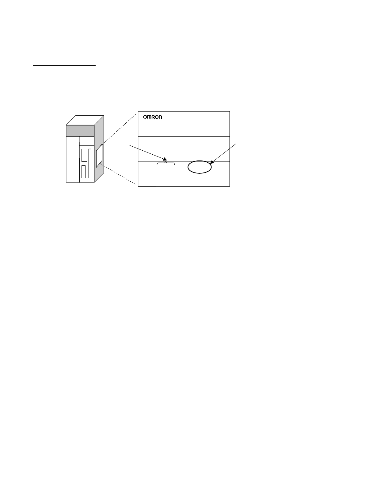
Notation of Unit Versions
on Products
CS/CJ-series CPU Unit
The unit version is given to the right of the lot number on the nameplate of the
products for which unit versions are being managed, as shown below.
Product nameplate
CS1H-CPU67H
CPU UNIT
Lot No.
Lot No. 031001 0000 Ver.2.0
OMRON Corporation MADE IN JAPAN
Unit version
Example for Unit version 2.0
• CS1-H, CJ1-H, and CJ1M CPU Units (except for low-end models) manufactured on or before November 4, 2003 do not have a unit version given
on the CPU Unit (i.e., the location for the unit version shown above is
blank).
• The unit version of the CS1-H, CJ1-H, and CJ1M CPU Units, as well as
the CS1D CPU Units for Single-CPU Systems, begins at version 2.0.
• The unit version of the CS1D CPU Units for Duplex-CPU Systems, begins
at version 1.1.
• CPU Units for which a unit version is not given are called Pre-Ver. @.@
CPU Units, such as Pre-Ver. 2.0 CPU Units and Pre-Ver. 1.1 CPU Units.
Confirming Unit Versions
with Support Software
CX-Programmer version 4.0 can be used to confirm the unit version using one
of the following two methods.
• Using the PLC Information
• Using the Unit Manufacturing Information (This method can be used for
Special I/O Units and CPU Bus Units as well.)
Note CX-Programmer version 3.3 or lower cannot be used to confirm unit versions.
PLC Information
• If you know the device type and CPU type, select them in the Change
PLC Dialog Box, go online, and select PLC - Edit - Information from the
menus.
• If you don’t know the device type and CPU type, but are connected
directly to the CPU Unit on a serial line, select PLC - Auto Online to go
online, and then select PLC - Edit - Information from the menus.
vi
Page 5
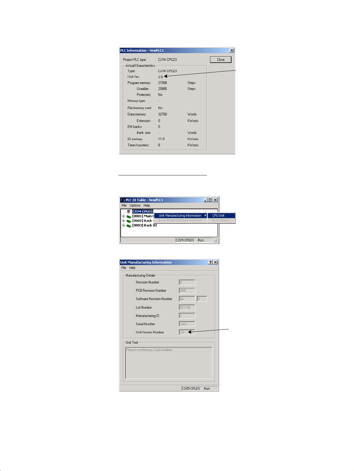
In either case, the following PLC Information Dialog Box will be displayed.
Unit version
Use the above display to confirm the unit version of the CPU Unit.
Unit Manufacturing Information
In the IO Table Window, right-click and select Unit Manufacturing informa-
tion - CPU Unit.
The following Unit Manufacturing information Dialog Box will be displayed
Unit version
Use the above display to confirm the unit version of the CPU Unit connected
online.
vii
Page 6
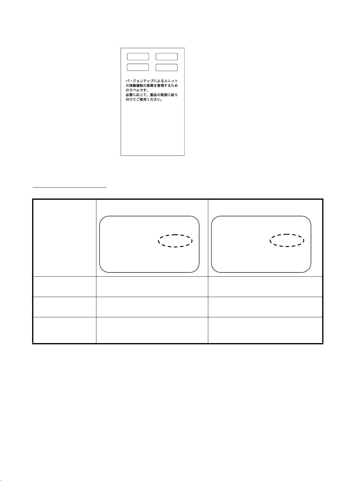
Using the Unit Version
Labels
The following unit version labels are provided with the CPU Unit.
Ver.
2.0
Ver.
2.0
These Labels can be
used to manage
differences in the
available functions
among the Units.
Place the appropriate
label on the front of
the Unit to show what
Unit version is
actually being used.
Ver.
Ver.
These labels can be attached to the front of previous CPU Units to differentiate between CPU Units of different unit versions.
Unit Version Notation In this manual, the unit version of a CPU Unit is given as shown in the follow-
ing table.
Product nameplate
CPU Units on which no unit version is
given
Units on which a version is given
(Ver. @.@)
Meaning
Designating individual
CPU Units (e.g., the
CS1H-CPU67H)
Designating groups of
CPU Units (e.g., the
CS1-H CPU Units)
Designating an entire
series of CPU Units
(e.g., the CS-series CPU
Units)
Lot No. XXXXXX XXXX
OMRON Corporation MADE IN JAPA
N
Lot No. XXXXXX XXXX Ver.@@.@
OMRON Corporation MADE IN JAPA
Pre-Ver. 2.0 CS1-H CPU Units CS1H-CPU67H CPU Unit Ver. @.@
Pre-Ver. 2.0 CS1-H CPU Units CS1-H CPU Units Ver. @.@
Pre-Ver. 2.0 CS-series CPU Units CS-series CPU Units Ver. @.@
N
viii
Page 7
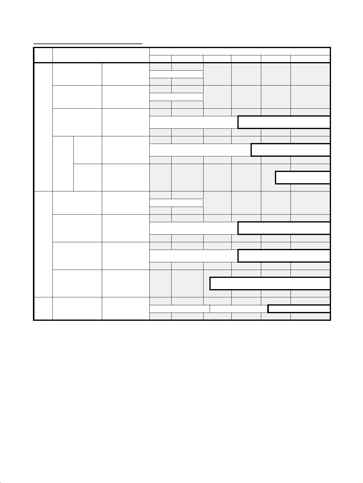
Unit Versions and Lot Numbers
Series Model Data of manufacture
Earlier Sept. 2003 Oct. 2003 Nov. 2003 Dec. 2003 Later
CS
Series
CS1 CPU Units CS1@-CPU@@
CS1-V1 CPU Units CS1@-CPU@@-V1
CS1-H CPU Units CS1@-CPU@@H
No unit version
No unit version
Pre-Ver. 2.0 CPU Units
CPU Units Ver. 2.0
(Lot No.: 031105 on)
CJ
Series
Support
Software
CS1D
CPU
Units
CJ1 CPU Units CJ1G-CPU@@
CJ1-H CPU Units CJ1@-CPU@@H
CJ1M CPU Units
except low-end models
CJ1M CPU Units,
low-end models
CX-Programmer WS02-CXPC1-EV@
CPU Units
for DuplexCPU System
CPU Units
for SingleCPU System
CS1D-CPU@@H
CS1D-CPU@@S
CJ1M-CPU@@
CJ1M-CPU11/21
Pre-Ver. 1.1 CPU Units
Pre-Ver. 2.0 CPU Units
Pre-Ver. 2.0 CPU Units
Pre-Ver. 2.0 CPU Units
Unit Ver. 2.0
(Lot No.: 031002 on)
Ver.3.2 Ver.3.3 Ver.4.0
CPU Units Ver.1.1
(Lot No.: 031120 on)
CPU Units Ver. 2.0
(Lot No.: 031215 on)
CPU Units Ver. 2.0
(Lot No.: 031105 on)
CPU Units Ver. 2.0
(Lot No.: 031105 on)
ix
Page 8

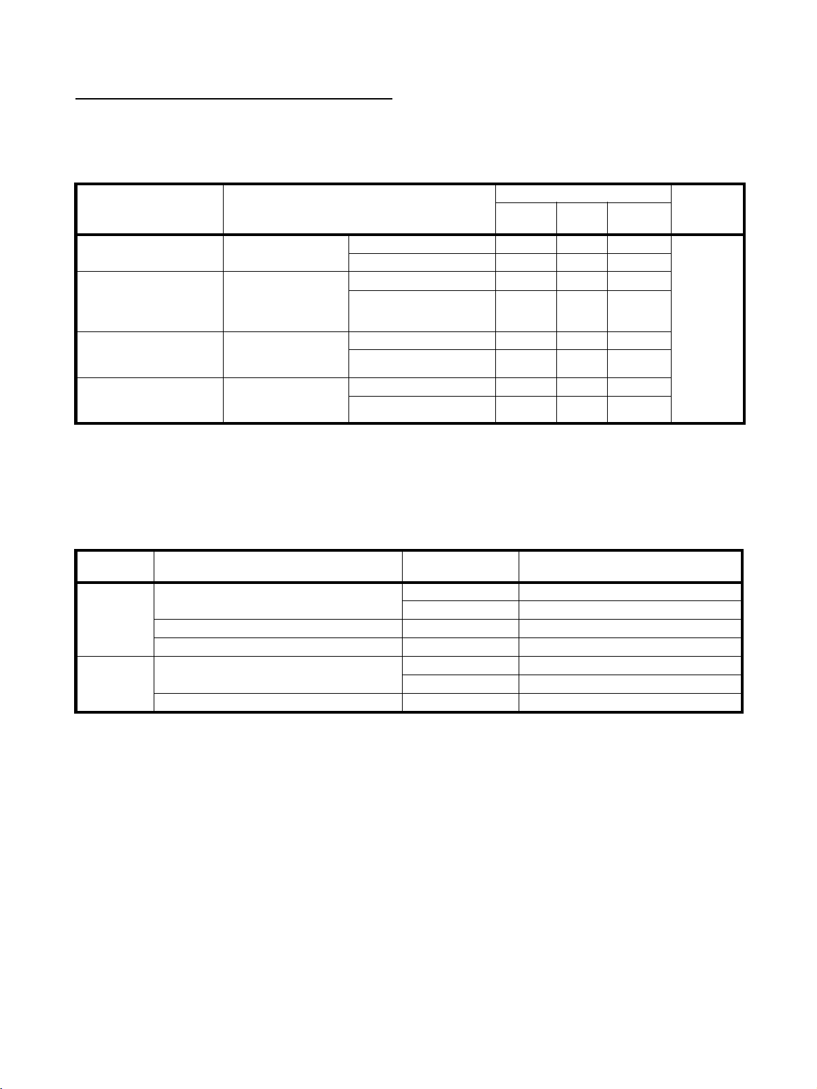
Function Support by Unit Version
CS1-H CPU Units (CS1@-CPU@@H)
Function Unit version
Pre-Ver. 2.0 CPU
Units
Downloading and Uploading Individual Tasks --- OK
Improved Read Protection Using Passwords --- OK
Write Protection from FINS Commands Sent to CPU Units via Networks
Online Network Connections without I/O Tables --- OK
Communications through a Maximum of 8 Network Levels --- OK
Connecting Online to PLCs via NS-series PTs OK from lot number
Setting First Slot Words OK for up to 8 groups OK for up to 64 groups
Automatic Transfers at Power ON without a Parameter File --- OK
Automatic Detection of I/O Allocation Method for Automatic Transfer
at Power ON
Operation Start/End Times --- OK
New Application Instructions
MILH, MILR, MILC --- OK
=DT, <>DT, <DT, <=DT, >DT, >=DT --- OK
BCMP2 --- OK
GRY OK from lot number
TPO --- OK
DSW, TKY, HKY, MTR, 7SEG --- OK
EXPLT, EGATR, ESATR, ECHRD, ECHWR --- OK
Reading/Writing CPU Bus Units with IORD/IOWR OK from lot number
PRV2 --- ---
--- OK
030201
--- ---
030201
030418
CPU Units Ver. 2.0
OK
OK
OK
x
Page 9

CS1D CPU Units
Function CS1D CPU Units for Duplex-CPU Systems
Pre-Ver. 1.1 CPU
Functions
unique to
CS1D CPU
Units
Downloading and Uploading Individual Tasks --- --- OK
Improved Read Protection Using Passwords --- --- OK
Write Protection from FINS Commands Sent
to CPU Units via Networks
Online Network Connections without I/O
Ta bl e s
Communications through a Maximum of 8
Network Levels
Connecting Online to PLCs via NS-series PTs --- --- OK
Setting First Slot Words --- --- OK for up to 64
Automatic Transfers at Power ON without a
Parameter File
Automatic Detection of I/O Allocation Method
for Automatic Transfer at Power ON
Operation Star t/End Times --- OK OK
New Application Instructions
Duplex CPU Units OK OK ---
Online Unit Replacement OK OK OK
Duplex Power Supply Units OK OK OK
Duplex Controller Link Units OK OK OK
Duplex Ethernet Units --- OK OK
--- --- OK
--- --- OK
--- --- OK
--- --- OK
--- --- ---
MILH, MILR, MILC --- --- OK
=DT, <>DT, <DT, <=DT, >DT,
>=DT
BCMP2 --- --- OK
GRY --- --- OK
TPO --- --- OK
DSW, TKY, HKY, MTR, 7SEG --- --- OK
EXPLT, EGATR, ESATR,
ECHRD, ECHWR
Reading/Writing CPU Bus
Units with IORD/IOWR
PRV2 --- --- ---
--- --- OK
--- --- OK
--- --- OK
(CS1D-CPU@@H)
CPU Unit Ver. 1.1 CPU Unit Ver. 2.0
Units
CS1D CPU Units
for Single-CPU
Systems
(CS1D-CPU@@S)
groups
xi
Page 10

CJ1-H/CJ1M CPU Units
Function CJ1-H CPU Units
Downloading and Uploading
Individual Tasks
Improved Read Protection
Using Passwords
Write Protection from FINS
Commands Sent to CPU Units
via Networks
Online Network Connections
without I/O Tables
Communications through a
Maximum of 8 Network Levels
Connecting Online to PLCs via
NS-series PTs
Setting First Slot Words --- OK --- OK OK
Automatic Transfers at Power
ON without a Parameter File
Automatic Detection of I/O Allocation Method for Automatic
Transfer at Power ON
Operation Start/End Times --- OK --- OK OK
New
Application
Instructions
MILH, MILR, MILC --- OK --- OK OK
=DT, <>DT, <DT,
<=DT, >DT, >=DT
BCMP2 --- OK OK OK OK
GRY OK from lot
TPO --- OK --- OK OK
DSW, TKY, HKY,
MTR, 7SEG
EXPLT, EGATR,
ESATR, ECHRD,
ECHWR
Reading/Writing
CPU Bus Units with
IORD/IOWR
PRV2 --- --- --- OK, but only for
--- OK --- OK OK
--- OK --- OK OK
--- OK --- OK OK
OK, but only if I/
O table allocation at power
ON is set
OK for up to 8
groups
OK from lot
number 030201
--- OK --- OK OK
--- OK --- OK OK
--- OK --- OK OK
number 030201
--- OK --- OK OK
--- OK --- OK OK
--- OK --- OK OK
(CJ1@-CPU@@H)
Pre-Ver. 2.0
CPU Units
CPU Units Ver.
2.0
OK OK, but only if I/
OK for up to 64
groups
OK OK from lot
OK OK from lot
O table allocation at power
ON is set
OK for up to 8
groups
number 030201
number 030201
CJ1M CPU Units,
except low-end models
(CJ1M-CPU@@)
Pre-Ver. 2.0
CPU Units
CPU Units Ver.
OK OK
OK for up to 64
groups
OK OK
OK OK
models with
built-in I/O
2.0
CJ1M CPU
Units, low-end
models
(CJ1M-CPU11/
21)
CPU Units Ver.
2.0
OK for up to 64
groups
OK, but only for
models with
built-in I/O
xii
Page 11
Unit Versions and Programming Devices
CX-Programmer version 4.0 or higher must be used to enable using the functions added for CPU Unit Ver. 2.0. The following tables show the relationship
between unit versions and CX-Programmer versions.
Unit Versions and Programming Devices
CPU Unit Functions CX-Programmer Program-
CJ1M CPU Units, lowend models, Unit Ver. 2.0
CS1-H, CJ1-H, and
CJ1M CPU Units except
low-end models, Unit Ver.
2.0
CS1D CPU Units for Single-CPU Systems, Unit
Ver. 2 . 0
CS1D CPU Units for
Duplex-CPU Systems,
Unit Ver.1.
Functions added for
unit version 2.0
Functions added for
unit version 2.0
Functions added for
unit version 2.0
Functions added for
unit version 1.1
Using new functions --- --- OK No
Not using new functions --- OK OK
Using new functions --- --- OK
Not using new functions OK OK OK
Using new functions --- --- OK
Not using new functions
Using new functions --- --- OK
Not using new functions OK OK OK
Note As shown above, there is no need to upgrade to CX-Programmer version 4.0
as long as the functions added for unit version 2.0 or unit version 1.1 are not
used.
Ver. 3.2
or lower
Ver. 3.3 Ver. 4.0
or higher
ming Con-
sole
restrictions
Device Type Setting The unit version does not affect the setting made for the device type on the
CX-Programmer. Select the device type as shown in the following table
regardless of the unit version of the CPU Unit.
Series CPU Unit group CPU Unit model Device type setting on
CX-Programmer Ver. 4.0 or higher
CS Series CS1-H CPU Units
CS1D CPU Units for Duplex-CPU Systems CS1D-CPU@@H CS1D-H (or CS1H-H)
CS1D CPU Units for Single-CPU Systems
CJ Series CJ1-H CPU Units
CJ1M CPU Units CJ1M-CPU@@ CJ1M
CS1G-CPU@@H CS1G-H
CS1H-CPU@@H CS1H-H
CS1D-CPU@@S CS1D-S
CJ1G-CPU@@H CJ1G-H
CJ1H-CPU@@H CJ1H-H
xiii
Page 12
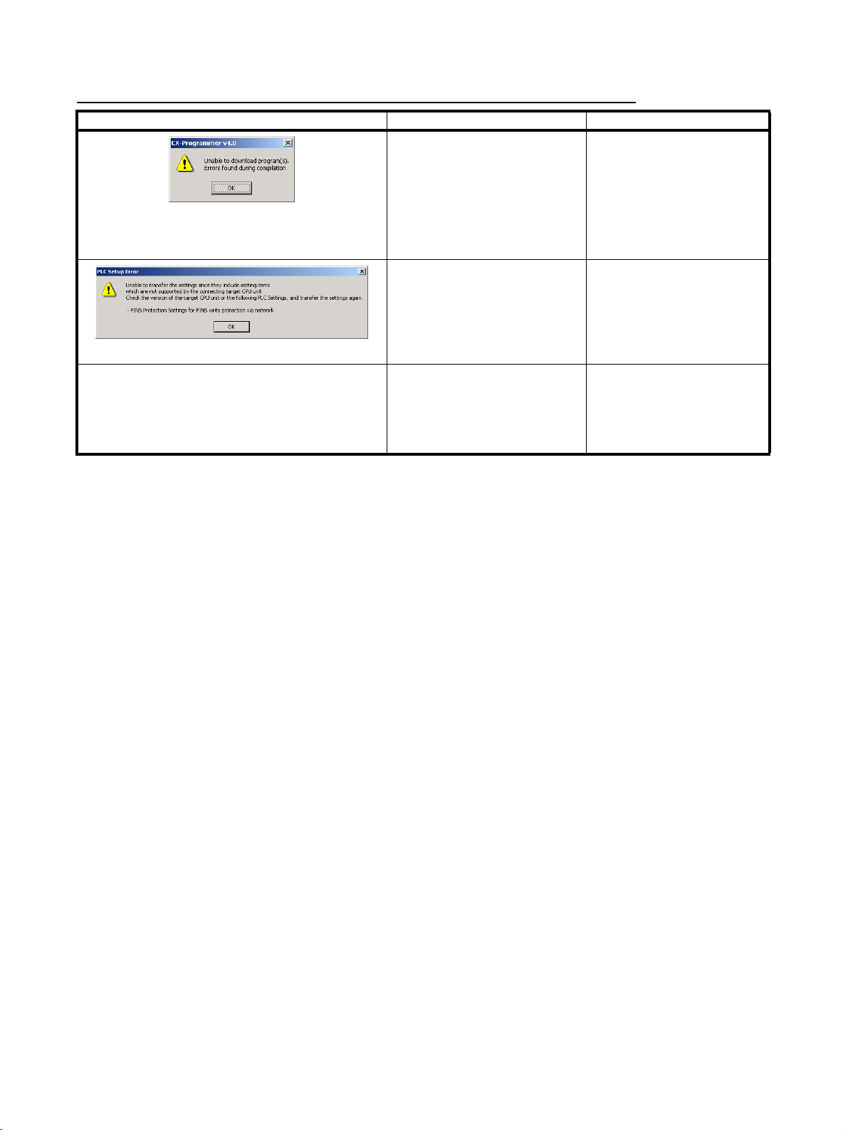
Troubleshooting Problems with Unit Versions on the CX-Programmer
Problem Cause Solution
After the above message is displayed, a compiling
error will be displayed on the Compile Tab Page in the
Output Window.
“????” is displayed in a program transferred from the
PLC to the CX-Programmer.
An attempt was made using CXProgrammer version 4.0 or higher
to download a program containing instructions supported only by
CPU Units Ver. 2.0 or later to a
Pre-Ver. 2.0 CPU Units.
An attempt was made using CXProgrammer version 4.0 or higher
to download a PLC Setup containing settings supported only by
CPU Units Ver. 2.0 or later (i.e.,
not set to their default values) to a
Pre-Ver. 2.0 CPU Units.
CX-Programmer version 3.3 or
lower was used to upload a program containing instructions supported only by CPU Units Ver. 2.0
or later from a CPU Unit Ver. 2.0
or later.
Check the program or change
the CPU Unit being downloaded to a CPU Unit Ver. 2.0
or later.
Check the settings in the PLC
Setup or change the CPU Unit
being downloaded to a CPU
Unit Ver. 2.0 or later.
The new instructions cannot
be uploaded using CX-Programmer version 3.3 or lower.
Use CX-Programmer version
4.0 or higher.
xiv
Page 13

TABLE OF CONTENTS
PRECAUTIONS . . . . . . . . . . . . . . . . . . . . . . . . . . . . . . . . . . . xxiii
1 Intended Audience . . . . . . . . . . . . . . . . . . . . . . . . . . . . . . . . . . . . . . . . . . . . . . . . . . . . . . . . xxiv
2 General Precautions . . . . . . . . . . . . . . . . . . . . . . . . . . . . . . . . . . . . . . . . . . . . . . . . . . . . . . . xxiv
3 Safety Precautions. . . . . . . . . . . . . . . . . . . . . . . . . . . . . . . . . . . . . . . . . . . . . . . . . . . . . . . . . xxiv
4 Operating Environment Precautions . . . . . . . . . . . . . . . . . . . . . . . . . . . . . . . . . . . . . . . . . . . xxv
5 Application Precautions . . . . . . . . . . . . . . . . . . . . . . . . . . . . . . . . . . . . . . . . . . . . . . . . . . . . xxvi
SECTION 1
Installation. . . . . . . . . . . . . . . . . . . . . . . . . . . . . . . . . . . . . . . . 1
1-1 Applicable Models . . . . . . . . . . . . . . . . . . . . . . . . . . . . . . . . . . . . . . . . . . . . . . . . . . . . . . . . 2
1-2 Using the Programming Console . . . . . . . . . . . . . . . . . . . . . . . . . . . . . . . . . . . . . . . . . . . . . 3
1-3 Programming Console Functions . . . . . . . . . . . . . . . . . . . . . . . . . . . . . . . . . . . . . . . . . . . . . 5
1-4 Unsupported Functions . . . . . . . . . . . . . . . . . . . . . . . . . . . . . . . . . . . . . . . . . . . . . . . . . . . . .7
1-5 Functions and Nomenclature . . . . . . . . . . . . . . . . . . . . . . . . . . . . . . . . . . . . . . . . . . . . . . . . 7
1-6 Programming Console Connection and Installation . . . . . . . . . . . . . . . . . . . . . . . . . . . . . . . 14
1-7 Comparison with Previous Models . . . . . . . . . . . . . . . . . . . . . . . . . . . . . . . . . . . . . . . . . . . . 16
SECTION 2
Using the Programming Console . . . . . . . . . . . . . . . . . . . . . 17
2-1 Programming. . . . . . . . . . . . . . . . . . . . . . . . . . . . . . . . . . . . . . . . . . . . . . . . . . . . . . . . . . . . . 18
2-2 Connecting the Programming Console . . . . . . . . . . . . . . . . . . . . . . . . . . . . . . . . . . . . . . . . . 19
2-3 Using the Programming Console for the First Time. . . . . . . . . . . . . . . . . . . . . . . . . . . . . . . 19
2-4 Inputting Programs . . . . . . . . . . . . . . . . . . . . . . . . . . . . . . . . . . . . . . . . . . . . . . . . . . . . . . . . 22
2-5 Checking Program Operation . . . . . . . . . . . . . . . . . . . . . . . . . . . . . . . . . . . . . . . . . . . . . . . . 26
SECTION 3
Operation. . . . . . . . . . . . . . . . . . . . . . . . . . . . . . . . . . . . . . . . . 31
3-1 Starting Operation . . . . . . . . . . . . . . . . . . . . . . . . . . . . . . . . . . . . . . . . . . . . . . . . . . . . . . . . . 32
3-2 Changing Operating Modes . . . . . . . . . . . . . . . . . . . . . . . . . . . . . . . . . . . . . . . . . . . . . . . . . 35
3-3 Key Functions . . . . . . . . . . . . . . . . . . . . . . . . . . . . . . . . . . . . . . . . . . . . . . . . . . . . . . . . . . . . 36
3-4 Clearing Memory Areas . . . . . . . . . . . . . . . . . . . . . . . . . . . . . . . . . . . . . . . . . . . . . . . . . . . .37
3-5 Buzzer Operation . . . . . . . . . . . . . . . . . . . . . . . . . . . . . . . . . . . . . . . . . . . . . . . . . . . . . . . . . 42
3-6 Selecting Tasks . . . . . . . . . . . . . . . . . . . . . . . . . . . . . . . . . . . . . . . . . . . . . . . . . . . . . . . . . . . 43
3-7 I/O Table Operations . . . . . . . . . . . . . . . . . . . . . . . . . . . . . . . . . . . . . . . . . . . . . . . . . . . . . . . 46
SECTION 4
Writing and Editing Programs . . . . . . . . . . . . . . . . . . . . . . . 53
4-1 Inputting Instructions . . . . . . . . . . . . . . . . . . . . . . . . . . . . . . . . . . . . . . . . . . . . . . . . . . . . . . 54
4-2 Reading and Searching Programs . . . . . . . . . . . . . . . . . . . . . . . . . . . . . . . . . . . . . . . . . . . . . 67
4-3 Editing Programs. . . . . . . . . . . . . . . . . . . . . . . . . . . . . . . . . . . . . . . . . . . . . . . . . . . . . . . . . . 71
xv
Page 14

TABLE OF CONTENTS
SECTION 5
Checking and Adjusting Programs . . . . . . . . . . . . . . . . . . . . 79
5-1 Reading Program Execution Status . . . . . . . . . . . . . . . . . . . . . . . . . . . . . . . . . . . . . . . . . . . . 80
5-2 Simple I/O Monitor . . . . . . . . . . . . . . . . . . . . . . . . . . . . . . . . . . . . . . . . . . . . . . . . . . . . . . . . 81
5-3 I/O Multipoint Monitor . . . . . . . . . . . . . . . . . . . . . . . . . . . . . . . . . . . . . . . . . . . . . . . . . . . . . 87
5-4 Monitor Display Format . . . . . . . . . . . . . . . . . . . . . . . . . . . . . . . . . . . . . . . . . . . . . . . . . . . .90
5-5 Changing Word (16-bit) Present Values . . . . . . . . . . . . . . . . . . . . . . . . . . . . . . . . . . . . . . . . 95
5-6 Forcing Bits ON/OFF . . . . . . . . . . . . . . . . . . . . . . . . . . . . . . . . . . . . . . . . . . . . . . . . . . . . . . 101
5-7 Differential Monitor. . . . . . . . . . . . . . . . . . . . . . . . . . . . . . . . . . . . . . . . . . . . . . . . . . . . . . . . 103
5-8 Online Editing . . . . . . . . . . . . . . . . . . . . . . . . . . . . . . . . . . . . . . . . . . . . . . . . . . . . . . . . . . . . 104
SECTION 6
Maintenance Operations . . . . . . . . . . . . . . . . . . . . . . . . . . . . 115
6-1 Clock Read/Change . . . . . . . . . . . . . . . . . . . . . . . . . . . . . . . . . . . . . . . . . . . . . . . . . . . . . . . . 116
6-2 Cycle Time Read . . . . . . . . . . . . . . . . . . . . . . . . . . . . . . . . . . . . . . . . . . . . . . . . . . . . . . . . . . 117
6-3 Reading/Clearing Error Messages. . . . . . . . . . . . . . . . . . . . . . . . . . . . . . . . . . . . . . . . . . . . . 118
SECTION 7
Memory Card Operations . . . . . . . . . . . . . . . . . . . . . . . . . . . 123
7-1 File Memory Operations . . . . . . . . . . . . . . . . . . . . . . . . . . . . . . . . . . . . . . . . . . . . . . . . . . . .124
7-2 Memory Card Format . . . . . . . . . . . . . . . . . . . . . . . . . . . . . . . . . . . . . . . . . . . . . . . . . . . . . .125
7-3 File Write. . . . . . . . . . . . . . . . . . . . . . . . . . . . . . . . . . . . . . . . . . . . . . . . . . . . . . . . . . . . . . . . 126
7-4 File Read . . . . . . . . . . . . . . . . . . . . . . . . . . . . . . . . . . . . . . . . . . . . . . . . . . . . . . . . . . . . . . . . 130
7-5 File Verify . . . . . . . . . . . . . . . . . . . . . . . . . . . . . . . . . . . . . . . . . . . . . . . . . . . . . . . . . . . . . . . 134
7-6 File Delete . . . . . . . . . . . . . . . . . . . . . . . . . . . . . . . . . . . . . . . . . . . . . . . . . . . . . . . . . . . . . . . 137
SECTION 8
PLC Setup Procedure . . . . . . . . . . . . . . . . . . . . . . . . . . . . . . . 141
8-1 PLC Setup Procedure. . . . . . . . . . . . . . . . . . . . . . . . . . . . . . . . . . . . . . . . . . . . . . . . . . . . . . . 142
Appendices
A ASCII Coding Sheet . . . . . . . . . . . . . . . . . . . . . . . . . . . . . . . . . . . . . . . . . . . . . . . . . . . . . . .145
B Error Messages . . . . . . . . . . . . . . . . . . . . . . . . . . . . . . . . . . . . . . . . . . . . . . . . . . . . . . . . . . . 147
C PLC Setup Coding Sheets for Programming Console . . . . . . . . . . . . . . . . . . . . . . . . . . . . . 149
Index. . . . . . . . . . . . . . . . . . . . . . . . . . . . . . . . . . . . . . . . . . . . . 161
Revision History . . . . . . . . . . . . . . . . . . . . . . . . . . . . . . . . . . . 165
xvi
Page 15

About this Manual:
This manual describes the installation and operation of the CQM1H-PRO01-E, CQM1-PRO01-E and
C200H-PRO27-E Programming Consoles for use with CS-series and CJ-series Programmable Controllers and includes the sections described below. The CS Series and CJ Series are subdivided as
shown in the following table.
Unit CS Series CJ Series
CPU Units CS1-H CPU Units: CS1H-CPU@@H
CS1 CPU Units: CS1H-CPU@@-EV1
CS1D CPU Units:
CS1D CPU Units for Duplex-CPU Systems:
CS1D-CPU@@H
CS1D CPU Units for Single-CPU Systems:
CS1D-CPU@@S
CS1D Process CPU Units:
CS1D-CPU@@P
Basic I/O Units CS-series Basic I/O Units CJ-series Basic I/O Units
Special I/O Units CS-series Special I/O Units CJ-series Special I/O Units
CPU Bus Units CS-series CPU Bus Units CJ-series CPU Bus Units
Power Supply Units CS-series Power Supply Units
Note: Use the special CS1D Power Supply
CS1G-CPU@@H
CS1G-CPU@@-EV1
Units for CS1D PLCs.
CJ1-H CPU Units: CJ1H-CPU@@H
CJ1G-CPU@@H
CJ1 CPU Units: CJ1G-CPU@@-EV1
CJ1M CPU Units: CJ1M-CPU@@
CJ-series Power Supply Units
Please read this manual and all related manuals listed in the table on the next page carefully and be
sure you understand the information provided before attempting to use the CQM1H-PRO01-E, CQM1PRO01-E, or C200H-PRO27-E Programming Console to program, set up, or operate a PLC System.
Section 1 gives a brief overview of the functions performed by the Programming Console, as well as
Programming Console specifications and connection procedures. It also lists the differences between
the operation of the Programming Consoles for CS/CJ-series PLCs and previous Programming Consoles.
Section 2 provides information on how to set up the Programming Console for operation. It also
describes how to write a simple program from the Programming Console.
Section 3 describes the basic operations of the Programming Console, including initializing memory
and creating I/O tables. The three input modes available on the Programming Console are also
described.
Section 4 describes how to create and edit programs from the Programming Console.
Section 5 describes how to monitor programs in different display modes to check and modify the user
programs. Change values from various displays is also described.
Section 6 includes information on reading and setting the clock, reading the cycle time, and reading/
clearing error messages.
Section 7 provides information on how to format Memory Cards before use, and procedures for transferring data between Memory Cards and the CPU Unit.
Section 8 lists the settings in the PLC Setup.
Appendix A provides a ASCII coding list, Appendix B provides a list of operating error messages,
and Appendix C provides a PLC Setup Setting Sheets.
xvii
Page 16

About this Manual, Continued
Name Cat. No. Contents
SYSMAC CS/CJ Series
Programming Consoles Operation Manual
CQM1H-PRO01-E, CQM1-PRO01-E,
C200H-PRO27-E
SYSMAC CS Series
CS1G/H-CPU@@-EV1, CS1G/H-CPU@@H
Programmable Controllers Operation Manual
SYSMAC CJ Series
CJ1G-CPU@@, CJ1G/H-CPU@@H
Programmable Controllers Operation Manual
SYSMAC CS Series
CS1D-CPU@@H CPU Units
CS1D-CPU@@S CPU Units
CS1D-DPL01 Duplex Unit
CS1D-PA/PD@@@ Power Supply Unit
Duplex System Operation Manual
W341 Provides information on how to program and operate
CS/CJ-series PLCs using a Programming Console.
(This manual)
W339 Describes the installation and operation of the CS-
series PLCs.
W393 Describes the installation and operation of the CJ-series
PLCs.
W405 Describes the installation and operation of the Duplex
System based on CS1D CPU Units.
SYSMAC CS/CJ Series
CS1G/H-CPU@@-EV1, CS1G/H-CPU@@H,
CS1D-CPU@@H/S, CJ1G-CPU@@,
CJ1G/H-CPU@@H
Programmable Controllers Programming Manual
SYSMAC CS/CJ Series
CS1G/H-CPU@@-EV1, CS1G/H-CPU@@H,
CS1D-CPU@@H/S, CJ1G-CPU@@,
CJ1G/H-CPU@@H
Programmable Controllers
Instructions Reference Manual
SYSMAC
CX-Programmer Operation Manual
WS02-CXP@@-E
SYSMAC
CX-Programmer Operation Manual
WS02-CXP@@-EV4
W394 Describes the ladder diagram programming functions
and other functions supported by CS-series and CJseries PLCs.
W340 Describes the ladder diagram programming instructions
supported by CS-series and CJ-series PLCs.
W414 Provides information on how to use the CX-Program-
mer, a programming device that supports the CS/CJseries PLCs, and the CX-Net contained within CX-Pro-
W425
grammer.
!WARNING Failure to read and understand the information provided in this manual may result in per-
sonal injury or death, damage to the product, or product failure. Please read each section
in its entirety and be sure you understand the information provided in the section and
related sections before attempting any of the procedures or operations given.
xviii
Page 17

Read and Understand this Manual
Please read and understand this manual before using the product. Please consult your OMRON
representative if you have any questions or comments.
Warranty and Limitations of Liability
WARRANTY
OMRON's exclusive warranty is that the products are free from defects in materials and workmanship for a
period of one year (or other period if specified) from date of sale by OMRON.
OMRON MAKES NO WARRANTY OR REPRESENTATION, EXPRESS OR IMPLIED, REGARDING NONINFRINGEMENT, MERCHANTABILITY, OR FITNESS FOR PARTICULAR PURPOSE OF THE
PRODUCTS. ANY BUYER OR USER ACKNOWLEDGES THAT THE BUYER OR USER ALONE HAS
DETERMINED THAT THE PRODUCTS WILL SUITABLY MEET THE REQUIREMENTS OF THEIR
INTENDED USE. OMRON DISCLAIMS ALL OTHER WARRANTIES, EXPRESS OR IMPLIED.
LIMITATIONS OF LIABILITY
OMRON SHALL NOT BE RESPONSIBLE FOR SPECIAL, INDIRECT, OR CONSEQUENTIAL DAMAGES,
LOSS OF PROFITS OR COMMERCIAL LOSS IN ANY WAY CONNECTED WITH THE PRODUCTS,
WHETHER SUCH CLAIM IS BASED ON CONTRACT, WARRANTY, NEGLIGENCE, OR STRICT
LIABILITY.
In no event shall the responsibility of OMRON for any act exceed the individual price of the product on which
liability is asserted.
IN NO EVENT SHALL OMRON BE RESPONSIBLE FOR WARRANTY, REPAIR, OR OTHER CLAIMS
REGARDING THE PRODUCTS UNLESS OMRON'S ANALYSIS CONFIRMS THAT THE PRODUCTS
WERE PROPERLY HANDLED, STORED, INSTALLED, AND MAINTAINED AND NOT SUBJECT TO
CONTAMINATION, ABUSE, MISUSE, OR INAPPROPRIATE MODIFICATION OR REPAIR.
xix
Page 18

Application Considerations
SUITABILITY FOR USE
OMRON shall not be responsible for conformity with any standards, codes, or regulations that apply to the
combination of products in the customer's application or use of the products.
At the customer's request, OMRON will provide applicable third party certification documents identifying
ratings and limitations of use that apply to the products. This information by itself is not sufficient for a
complete determination of the suitability of the products in combination with the end product, machine,
system, or other application or use.
The following are some examples of applications for which particular attention must be given. This is not
intended to be an exhaustive list of all possible uses of the products, nor is it intended to imply that the uses
listed may be suitable for the products:
• Outdoor use, uses involving potential chemical contamination or electrical interference, or conditions or
uses not described in this manual.
• Nuclear energy control systems, combustion systems, railroad systems, aviation systems, medical
equipment, amusement machines, vehicles, safety equipment, and installations subject to separate
industry or government regulations.
• Systems, machines, and equipment that could present a risk to life or property.
Please know and observe all prohibitions of use applicable to the products.
NEVER USE THE PRODUCTS FOR AN APPLICATION INVOLVING SERIOUS RISK TO LIFE OR
PROPERTY WITHOUT ENSURING THAT THE SYSTEM AS A WHOLE HAS BEEN DESIGNED TO
ADDRESS THE RISKS, AND THAT THE OMRON PRODUCTS ARE PROPERLY RATED AND
INSTALLED FOR THE INTENDED USE WITHIN THE OVERALL EQUIPMENT OR SYSTEM.
PROGRAMMABLE PRODUCTS
OMRON shall not be responsible for the user's programming of a programmable product, or any
consequence thereof.
xx
Page 19

Disclaimers
CHANGE IN SPECIFICATIONS
Product specifications and accessories may be changed at any time based on improvements and other
reasons.
It is our practice to change model numbers when published ratings or features are changed, or when
significant construction changes are made. However, some specifications of the products may be changed
without any notice. When in doubt, special model numbers may be assigned to fix or establish key
specifications for your application on your request. Please consult with your OMRON representative at any
time to confirm actual specifications of purchased products.
DIMENSIONS AND WEIGHTS
Dimensions and weights are nominal and are not to be used for manufacturing purposes, even when
tolerances are shown.
PERFORMANCE DATA
Performance data given in this manual is provided as a guide for the user in determining suitability and does
not constitute a warranty. It may represent the result of OMRON's test conditions, and the users must
correlate it to actual application requirements. Actual performance is subject to the OMRON Warranty and
Limitations of Liability.
ERRORS AND OMISSIONS
The information in this manual has been carefully checked and is believed to be accurate; however, no
responsibility is assumed for clerical, typographical, or proofreading errors, or omissions.
xxi
Page 20

Page 21

PRECAUTIONS
This section provides general precautions for using the Programmable Controller (PLC) and related devices.
The information contained in this section is important for the safe and reliable application of the Programmable
Controller. You must read this section and understand the information contained before attempting to set up or
operate a PLC system.
1 Intended Audience . . . . . . . . . . . . . . . . . . . . . . . . . . . . . . . . . . . . . . . . . . . . . xxiv
2 General Precautions . . . . . . . . . . . . . . . . . . . . . . . . . . . . . . . . . . . . . . . . . . . . xxiv
3 Safety Precautions. . . . . . . . . . . . . . . . . . . . . . . . . . . . . . . . . . . . . . . . . . . . . . xxiv
4 Operating Environment Precautions . . . . . . . . . . . . . . . . . . . . . . . . . . . . . . . . xxv
5 Application Precautions . . . . . . . . . . . . . . . . . . . . . . . . . . . . . . . . . . . . . . . . . xxvi
xxiii
Page 22

Intended Audience 1
1 Intended Audience
This manual is intended for the following personnel, who must also have
knowledge of electrical systems (an electrical engineer or the equivalent).
• Personnel in charge of designing FA systems.
• Personnel in charge of managing FA systems and facilities.
2 General Precautions
The user must operate the product according to the performance specifications described in the operation manuals.
Before using the product under conditions which are not described in the
manual or applying the product to nuclear control systems, railroad systems,
aviation systems, vehicles, combustion systems, medical equipment, amusement machines, safety equipment, and other systems, machines, and equipment that may have a serious influence on lives and property if used
improperly, consult your OMRON representative.
Make sure that the ratings and performance characteristics of the product are
sufficient for the systems, machines, and equipment, and be sure to provide
the systems, machines, and equipment with double safety mechanisms.
This manual provides information for programming and operating the Unit. Be
sure to read this manual before attempting to use the Unit and keep this manual close at hand for reference during operation.
!WARNING It is extremely important that a PLC and all PLC Units be used for the speci-
fied purpose and under the specified conditions, especially in applications that
can directly or indirectly affect human life. You must consult with your OMRON
representative before applying a PLC System to the above-mentioned applications.
3 Safety Precautions
!WARNING Do not attempt to take any Unit apart while the power is being supplied. Doing
so may result in electric shock.
!WARNING Do not attempt to disassemble, repair, or modify any Units. Any attempt to do
so may result in malfunction, fire, or electric shock.
!Caution The CPU Unit refreshes I/O even when operation has been stopped in PRO-
GRAM mode. Always confirm safety before changing data in the output area
allocated to the Output Units or changing data in any memory area allocated
to Special I/O Units or CPU Bus Units using any of the following operations.
The loads connected to the Output Units, Special I/O Units, or CPU Bus Units
may operate unexpectedly.
• Transferring I/O memory to the CPU Unit using a peripheral device (personal computer software).
• Changing the present value using a peripheral device.
• Force-setting/resetting using a peripheral device.
• Transferring I/O memory files to the CPU Unit from the Memory Card or
EM File Memory.
xxiv
Page 23

Operating Environment Precautions 4
• Transferring I/O memory data from other personal computers or host
computers on the network.
!Caution Confirm that the equipment is operating safely before starting actual opera-
tion.
!Caution Execute online edit only after confirming that no adverse effects will be
caused by extending the cycle time. Otherwise, the input signals may not be
readable.
!Caution Confirm that no adverse effect will occur in the system before executing online
edit.
4 Operating Environment Precautions
!Caution Do not operate the control system in the following places:
• Locations subject to direct sunlight.
• Locations subject to temperatures or humidity outside the range specified
in the specifications.
• Locations subject to condensation as the result of severe changes in temperature.
• Locations subject to corrosive or flammable gases.
• Locations subject to dust (especially iron dust) or salts.
• Locations subject to exposure to water, oil, or chemicals.
• Locations subject to shock or vibration.
!Caution Take appropriate and sufficient countermeasures when installing systems in
the following locations:
• Locations subject to static electricity or other forms of noise.
• Locations subject to strong electromagnetic fields.
• Locations subject to possible exposure to radioactivity.
• Locations close to power supplies.
!Caution The operating environment of the PLC System can have a large effect on the
longevity and reliability of the system. Improper operating environments can
lead to malfunction, failure, and other unforeseeable problems with the PLC
System. Be sure that the operating environment is within the specified conditions at installation and remains within the specified conditions during the life
of the system.
xxv
Page 24

Application Precautions 5
5 Application Precautions
Observe the following precautions when using the PLC System.
!WARNING Always heed these precautions. Failure to abide by the following precautions
could lead to serious or possibly fatal injury.
• Always connect to a class-3 ground (to 100
Units. Not connecting to a class-3 ground may result in electric shock.
• Always turn OFF the power supply to the PLC before attempting any of
the following. Not turning OFF the power supply may result in malfunction
or electric shock.
• Mounting or dismounting I/O Units, CPU Unit, Power Supply Units, Inner Boards, or any other Units.
• Assembling the Units.
• Setting DIP switches or rotary switches.
• Connecting or wiring the cables.
• Connecting or disconnecting the connectors.
!Caution Failure to abide by the following precautions could lead to faulty operation of
the PLC or the system, or could damage the PLC or PLC Units. Always heed
these precautions.
• Fail-safe measures must be taken by the customer to ensure safety in the
event of incorrect, missing, or abnormal signals caused by broken signal
lines, momentary power interruptions, or other causes.
• Interlock circuits, limit circuits, and similar safety measures in external circuits (i.e., not in the Programmable Controller) must be provided by the
customer.
• Install external breakers and take other safety measures against short-circuiting in external wiring. Insufficient safety measures against short-circuiting may result in burning.
• Be sure that all the mounting screws, terminal screws, and cable connector screws are tightened to the torque specified in the relevant manuals.
Incorrect tightening torque may result in malfunction.
• Always use the power supply voltage specified in the operation manuals.
An incorrect voltage may result in malfunction or burning.
• Take appropriate measures to ensure that the specified power with the
rated voltage and frequency is supplied. Be particularly careful in places
where the power supply is unstable. An incorrect power supply may result
in malfunction.
• Do not apply voltages to the Input Units in excess of the rated input voltage. Excess voltages may result in burning.
• Do not apply voltages or connect loads to the Output Units in excess of
the maximum switching capacity. Excess voltage or loads may result in
burning.
• Wire the Unit correctly.
• Mount the Unit only after checking the terminal block completely.
Ω or less) when installing the
xxvi
Page 25

Application Precautions 5
• Use crimp terminals for wiring. Do not connect bare stranded wires
directly to terminals. Connection of bare stranded wires may result in
burning.
• Leave the label attached to the Unit when wiring. Removing the label may
result in malfunction.
• Remove the label after the completion of wiring to ensure proper heat dissipation. Leaving the label attached may result in malfunction.
• Disconnect the functional ground terminal when performing withstand
voltage tests. Not disconnecting the functional ground terminal may result
in burning.
• Check the orientation and polarity of terminal blocks and connectors
before connecting them.
• Be sure that the terminal blocks, expansion cables, and other items with
locking devices are properly locked into place. Improper locking may
result in malfunction.
• Double-check all the wiring before turning ON the power supply. Incorrect
wiring may result in burning.
• Check the user program for proper execution before actually running it on
the Unit. Not checking the program may result in an unexpected operation.
• Confirm that no adverse effect will occur in the system before attempting
any of the following. Not doing so may result in an unexpected operation.
• Changing the operating mode of the PLC.
• Force-setting/force-resetting any bit in memory.
• Changing the present value of any word or any set value in memory.
• Transfer any essential data for restarting the PLC, such as data memory
and hold bits to the CPU Unit before restarting the PLC.
• Do not pull on the cables or bend the cables beyond their natural limit.
Doing either of these may break the cables.
• Do not place objects on top of the cables. Doing so may break the cables.
• When replacing parts, be sure to confirm that the rating of a new part is
correct. Not doing so may result in malfunction or burning.
• Before touching the Unit, be sure to first touch a grounded metallic object
in order to discharge any static built-up. Not doing so may result in malfunction or damage.
xxvii
Page 26

Page 27

SECTION 1
Installation
This section describes the Programming Console used with CS/CJ-series PLCs. It includes a brief overview of the functions
performed by the Programming Console, as well as Programming Console installation procedures.
1-1 Applicable Models . . . . . . . . . . . . . . . . . . . . . . . . . . . . . . . . . . . . . . . . . . . . . 2
1-2 Using the Programming Console . . . . . . . . . . . . . . . . . . . . . . . . . . . . . . . . . . 3
1-3 Programming Console Functions . . . . . . . . . . . . . . . . . . . . . . . . . . . . . . . . . . 5
1-4 Unsupported Functions . . . . . . . . . . . . . . . . . . . . . . . . . . . . . . . . . . . . . . . . . . 7
1-5 Functions and Nomenclature . . . . . . . . . . . . . . . . . . . . . . . . . . . . . . . . . . . . . 7
1-5-1 Nomenclature . . . . . . . . . . . . . . . . . . . . . . . . . . . . . . . . . . . . . . . . . . 8
1-5-2 The Mode Switch and Operating Modes . . . . . . . . . . . . . . . . . . . . . 10
1-5-3 Key Functions . . . . . . . . . . . . . . . . . . . . . . . . . . . . . . . . . . . . . . . . . . 11
1-6 Programming Console Connection and Installation . . . . . . . . . . . . . . . . . . . . 14
1-7 Comparison with Previous Models . . . . . . . . . . . . . . . . . . . . . . . . . . . . . . . . . 16
1
Page 28
Applicable Models Section 1-1
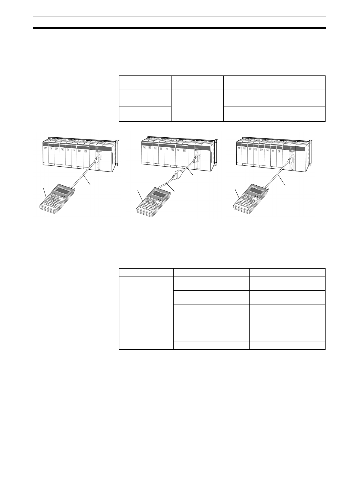
1-1 Applicable Models
Applicable Programming
Consoles
CS/CJ
CS1W-KS001-E
Key Sheet
Connecting Cable
provided with the
CQM1H-PRO01-E
CQM1H-PRO01-E
Any of the following Programming Consoles can be used with CS/CJ-series
PLCs: CQM1H-PRO01-E, CQM1-PRO01-E and the C200H-PRO27-E. The
Key Sheet and Connecting Cables listed below are required.
Programming
Console
CQM1H-PRO01-E
-PRO01-ECS1W-CN114 (0.05 m)
CQM1
C200H-PRO27-ECS1W-CN224 (2.0 m) or CS1W-CN624
CS/CJ
CS1W-KS001-E
Key Sheet
CQM1-PRO01-E
Key Sheet Connecting Cables
CS1W-KS001-E
2-m cable included
(6.0 m)
CS/CJ
CS1W-N114
Connecting Cable:
0.05 m
Connecting Cable
provided with the
CQM1H-PRO01-E
CS1W-KS001-E
Key Sheet
C200H-PRO27-E
CS1W-CN224: 2.0 m
CS1W-CN624: 6.0 m
The Programming Console is connected to the peripheral port on the CPU
Unit. It cannot be connected to the RS-232C port.
In a CS1D Duplex-CPU System, the Programming Console is connected to
the active CPU Unit.
Applicable CPU Units
Series CPU Units Abbreviation in this manual
CS Series CS1H-CPU6@-V1
CS1 CPU Unit
CS1G-CPU4@-V1
CS1H-CPU6@H
CS1-H CPU Unit
CS1G-CPU4@H
CS1D-CPU6@H
CS1D CPU Unit
CS1D-CPU@@S
CJ Series CJ1G-CPU4@ CJ1 CPU Unit
CJ1H-CPU6@H
CJ1-H CPU Unit
CJ1G-CPU4@H
CJ1M-CPU@@ CJ1M CPU Unit
2
Page 29

Using the Programming Console Section 1-2
Operational Differences
for CPU Units
The operation of the Programming Console will vary with the CPU Unit that is
connected as shown in the following table. These are the only differences in
Programming Console operation that vary with the CPU Unit.
Operation CS Series CJ Series
CS1
CPU Units
Operating mode when at startup
(when PLC Setup is set to the
default setting and the Programming Console is not connected)
Selecting the display language Pin 3 on DIP
PROGRAM RUN
switch on
front panel
of CPU Unit
CS1-H
CPU Units
Programming Console key switch
CJ1
CPU Units
CJ1-H
CPU Units
1-2 Using the Programming Console
Programming Console The Programming Console for CS/CJ-series PLCs is used to write, to make
on-site adjustments to, and to protect user programs. To create and edit relatively large user programs, the CX-Programmer (running on a Windows computer) should be used.
Programming Console
Features
Programming is started by using the CX-Programmer, a programming and
monitoring software package that runs on a Windows computer, to create the
program. Programming is completed by debugging the program on the PLC.
The Programming Console is used after programming has been completed to
change the operating mode, change sections of the ladder program, monitor
operation, change present values in I/O memory, change the PLC Setup, and
read error information. The Programming Console can also be used to transfer and verify data between EM File Memory and the PLC.
3
Page 30
Using the Programming Console Section 1-2
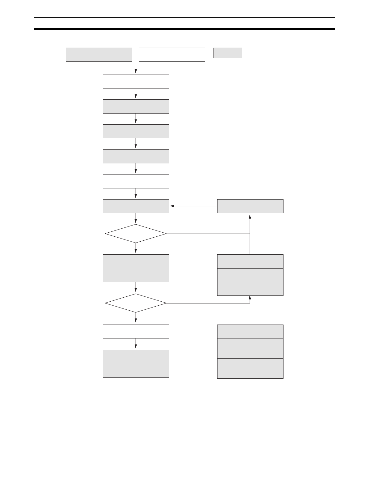
One Cyclic Task More than One Cyclic Task
Programming
Programming
Checking the program
Indicates operations
which can be performed
from the Programming
Console
Creating I/O tables
PLC Setup
Setting DM allocations
Transferring program to PLC
Debugging
OK?
Ye s
Trial operation
Monitoring
First rack words cannot be set.
Modifying the program
Online Editing
No
Changing the set values
for timers/counters
Making changes to
PLC Setup
Setting DM allocation
OK?
Ye s
Actual operation
Monitoring
Reading error information
on current errors
No
Formatting Memory
Cards/EM File Memory
Transferring data between
Memory Cards/EM files
and the PLC
Verifying data between
Memory Cards/EM files
and the PLC
Note The Programming Console cannot be used to create programs with more
than one cyclic task. Use the CX-Programmer if more than one cyclic task is
required.
4
Page 31

Programming Console Functions Section 1-3
1-3 Programming Console Functions
The Programming Console performs the following functions.
Operational Settings
Buzzer Operation.
Memory Clear
All Clear
Memory Clear
Creating/Verifying I/O Tables
I/O Table Create.
I/O Table Verify.
Maintenance
Reading/Clearing Error Messages.
Cycle Time Read.
Ladder Programming
Selecting Tasks
See p42.
Specifying memory areas not to clear.
Specifying the first program address to clear.
Specifying memory areas not to clear.
See p46.
See p48.
See p118.
See p117.
See p43.
See p39.
See p41.
See p41.
Program Read Setting Addresses
Searching
Program Write Instruction Write
Operand Input
Program Edit Instruction Change
Instruction Insert
Instruction Delete
Operand Change
N.O./N.C. Change
Instruction Variation Change
Timer/Counter SV change
Timer/Counter SV Change 1 (Sets constant or word)
Timer/Counter SV Change 2 (Fine adjustment of constant)
See p75.
See p76.
See p67.
Instruction Search
Bit Search
See p71.
See p72.
See p73.
See p74.
See p74.
See p68.
See p69.
5
Page 32

Programming Console Functions Section 1-3
Monitoring
Simple I/O Monitor
I/O Multipoint Monitor
Differential Monitor
Display Change
SV Change
Force Set/Reset
See p103.
Signed Decimal Monitor
Unsigned Decimal Monitor
ASCII Monitor
Word (Multipoint) Monitor
Hexadecimal/BCD Display Change
Signed Decimal Display Change
Unsigned Decimal Display Change
ASCII Display
Word (Multipoint) Display Change
Force Set/Reset
Force Set/Reset All Clear
See p81.
See p87.
See p92.
See p93.
See p94.
See p91.
See p96.
See p96.
See p98.
See p99.
See p100.
See p101.
See p103.
Online Editing
Special Functions
Clock Read/Change
PLC Setup
Memory Card Operations
See p98.
Program Edit
Instruction Variation Change
Timer/Counter SV Change
Timer/counter SV Change 1 (Sets constant or word)
Timer/counter SV Change 2 (Fine adjustment of constant)
See p116.
See Section 8.
See Section 7.
Data transfer from PLC to Memory Card
Data transfer from Memory Card to PLC
File Verify
File Delete
Memory Card format
See p134.
See p137.
Instruction Change
Instruction Insert
Instruction Delete
Bit Address Change
N.O./N.C. Change
See p110.
See p111.
See p125.
See p104.
See p106.
See p107.
See p108.
See p109.
See p125.
See p130.
6
Page 33

Unsupported Functions Section 1-4
1-4 Unsupported Functions
The following operations cannot be performed on the Programming Console.
Use the CX-Programmer to perform these operations.
• Creating several cyclic tasks.
• Checking programs.
• Operations related to Communications Units.
• Displaying error history information.
• Setting the first rack words.
• Data tracing.
• Setting and clearing program read protection.
1-5 Functions and Nomenclature
Handling Precautions Although the Programming Console does not require regular maintenance,
observe the following precautions.
• Do not subject the Programming Console to excessive shock during
transportation or operation. Handle the keypad and the LCD display with
care.
• The C200H-PRO27-E Programming Console has two connectors. Use
only one of them at a time.
• Connect the cable to the Programming Console firmly until you hear it
click into place, indicating that the cable is locked firmly in place.
• When removing the cable, hold the levers on both sides of the cable,
release the lock, and pull the cable out.
• Do not pull or twist the cable with excessive force.
• The ambient operating temperature is 0 to 55
perature is not exceeded when the Programming Console is used
mounted to a panel.
°C. Be careful that this tem-
Operating Environment Do not install or operate the Programming Console in any of the following
locations.
• Locations subject to temperatures or humidities outside the ranges specified in the specifications.
• Locations directly subject to excessive shock.
• Locations subject to strong magnetic fields or electromagnetic waves.
• Locations subject to direct sunlight.
7
Page 34

Functions and Nomenclature Section 1-5
1-5-1 Nomenclature
CQM1H-PRO01-E CQM1H-PRO01-E
LCD display
. IR+
FUNASFTBNOT
TN
AND
AA
LD
77889
E
4
B
1
A
0
DR
SHIFT
. IR
IR
C
F
D
E
*EM
. −IR
ST
TK
AR
TR
OR
CNT
HR
WR/LR
K
J
G
I
H
AC
OUT
N
M
F
5
4
5
C
2
1
2
TEXT
!
0
TIM
6
D
3
CLR
EM
DM
O
*EM_
EM_/EXT
9
SETVDELWMON
6
RESET
3
VRFY
L
CH
CONT
*DM
#
Q
R
P
CHG
SRCH
S
TCFU
X
INS
↑
Y
Z
WRITE
↓
Cable length: 2 m
(The CQM1H-PRO01-E can be connected
directly to the PLC.)
C200H-PRO27-E
FUNASFTBNOT
TN
ST
AND
OR
G
H
AA
AC
LD
OUT
N
M
77889
E
F
4
5
4
5
B
C
1
2
1
2
A
TEXT
0
!
0
TK
CNT
TIM
6
D
3
CLR
. IR+
. IR
C
. −IR
TR
I
EM
DM
O
*EM_
EM_/EXT
9
SETVDELWMON
6
RESET
3
VRFY
DR
IR
D
*EM
WR/LR
J
CH
*DM
P
CHG
S
INS
Y
WRITE
FUNASFTBNOT
TN
ST
AND
OR
G
AA
AC
LD
OUT
M
77889
E
F
4
5
4
B
C
1
2
1
A
TEXT
0
!
0
SHIFT
F
E
AR
HR
K
L
CONT
#
Q
R
SRCH
TCFU
X
↑
Z
↓
. IR+
DR
SHIFT
. IR
IR
C
F
D
E
*EM
. −IR
TK
AR
WR/LR
TR
CNT
HR
K
J
I
H
N
5
2
TIM
6
D
3
CLR
EM
DM
O
*EM_
EM_/EXT
9
SETVDELWMON
6
RESET
3
VRFY
L
CH
CONT
*DM
#
Q
R
P
CHG
SRCH
S
TCFU
X
INS
↑
Y
Z
WRITE
↓
Keys
Note: Install the CS1W-JS001-E Key Sheet
Connecting Cable
CS1W-CN114: 0.05 m
LCD display
Mode switch
Keys
Note: Install the CS1W-KS001-E Key Sheet
Mode switch
Cassette connector jack
Connecting Cables
CS1W-CN224: 2.0 m
CS1W-CN624: 6.0 m
8
Page 35

Functions and Nomenclature Section 1-5
Mode Switch The mode switch key can be removed from the switch when the switch is in
RUN or MONITOR modes. It cannot be removed when in PROGRAM mode.
f
f
MONITOR
RUN
Display Contrast The contrast of the liquid crystal display can be adjusted using the knob on
the right of the display.
Buzzer Volume With the C200H-PRO27-E Programming Console, the buzzer volume can be
adjusted using the lever on the right-hand side of the Console. The CQM1HPRO01-E and CQM1-PRO01-E does not have buzzer volume control.
✕
PROGRAM
Contrast adjustment knob
f: Key can be removed
✕: Key cannot be removed
Buzzer volume minimum
Buzzer volume maximum
C200H-PRO27-E
Programming
Console
Refer to 3-5 Buzzer Operation for further information on adjusting the buzzer
volume.
9
Page 36

Functions and Nomenclature Section 1-5
1-5-2 The Mode Switch and Operating Modes
The relation between the operating mode of the CPU Unit and the mode
switch is as follows:
Key operation Operating
MONITOR
RUN
PROGRAM
mode
PROGRAM
mode
The CPU Unit is stopped. Programming operations, such as writing or changing programs,
clearing memory, and checking the program,
can be performed.
Function
MONITOR
RUN
MONITOR
RUN
PROGRAM
PROGRAM
MONITOR
mode
RUN mode Used for normal operation of the CPU Unit.
The CPU Unit is operating and I/O processing
is being performed. In this mode, CPU Unit
operation can be monitored and functions
such as forcing bits ON/OFF, changing timer/
counter SV/PC, changing word data PVs, and
online editing can be used. This mode is often
used for making program adjustments and for
trial system operations.
The operating status of the CPU Unit can be
monitored in this mode, but functions such as
forcing bits ON/OFF and changing PVs and
SVs cannot be performed.
Startup Operating Mode The operating mode of the CPU Unit when the power is turned ON depends
on the status of address 81 in the PLC Setup (Startup Mode) and the connection status of peripheral devices.
Startup Mode setting in
PLC Setup (address 81)
PRCN: Mode set on Programming Console’s mode
switch
PRG: PROGRAM mode Not relevant PROGRAM mode
MON: MONITOR mode Not relevant MONITOR mode
RUN: RUN mode Not relevant RUN mode
Peripheral device Startup operating mode
Nothing connected CS1 CPU Unit:
PROGRAM mode
Programming Console connected
Peripheral device
other than Programming Console connected
CJ1/CJ1-H/CS1-H CPU Unit:
The mode set on the mode switch
on the Programming Console
CS1 CPU Unit:
CJ1/CJ1-H/CS1-H CPU Unit:
RUN mode
PROGRAM mode
RUN mode
10
Page 37

Functions and Nomenclature Section 1-5
Shift i
t
Shift i
t
1-5-3 Key Functions
Each key has three possible inputs: The normal input, a shift input, and a text
input. Refer to page 37.
FUN
A
Normal input
AR
HR
npu
Normal input Normal input
L
A
0
0
npu
Text input
• Press the SHIFT Key first to use the shift input.
• Press the SHIFT and then TEXT Keys first to use the text input.
Text input
Text input
Note Keystrokes for procedures are illustrated using graphics of the buttons on the
keypad for each step. The following list provides key names used in the text of
this manual.
Key Name Normal input Shift input Text input
FUN
A
Select/change task
PLC Setup
(shift, monitor etc.)
SFT Key SFT --- B
FUN Key Function code
SFT
B
NOT Key NOT --- C
NOT
C
,IR+
,IR
DR
IR
,IR+/,IR Key ,IR
D
DR/IR Key IR
E
(Indirect index register)
(Direct index register)DR(Data register)
SHIFT Key Alters the function of
SHIFT
F
TN
AND
ST
OR
TK
CNT
,–IR
TR
DISP
*EM
WR/LR
AR
HR
TN/AND Key AND --- G
G
ST/OR Key OR --- H
H
TK/CNT Key CNT (Counter) TK (Task flag) I
I
,–IR/TR Key Display changes
J
*EM/WR.LR
Key
K
AR/HR Key HR (Holding bits) AR
L
other keys.
TR (Temporary bit)
WR (Work bits)
LR (Link bits)
--- A
,IR+ D
--- F
,–IR
(Index register
-decre-
auto
ment)
*EM
Indirect EM
(Extended
data memory)
(Auxiliary bits)
E
J
K
L
11
Page 38

Functions and Nomenclature Section 1-5
Key Name Normal input Shift input Text input
AA
LD
AC
OUT
TIM
AA/LD Key LD --- M
M
AC/OUT Key OUT --- N
N
TIM Key TIM (Timer) --- O
O
EM
DM
CH
*DM
CONT
#
*EM_
EM_/EXT
CHG
CF
SRCH
SET
DEL
MON
RESET
INS
EM/DM Key DM (Data memory) EM
P
(Data memory
of current
bank)
CH/*DM Key *DM
Q
CONT/# Key #Constant
R
*EM_/EM_.EXT
Key
S
(Indirect data memory)
(Binary or BCD)
EM_
(Expansion Data Memory including bank
CIO word Q
Operand
(Bit address)
*EM (indirect
address)
number)
EXT (memory all clear)
CHG Key CHG
T
(Changes to SVs,
timer/counter etc.)
--- T
CF/SRCH Key SRCH CF
(Condition
U
SET Key SET
V
Flag)
-ON dif-
OFF
ferentiation
Force Reset
DEL Key DEL (Delete) --- W
W
MON Key MON
X
(Simple I/O Monitor, I/O
Multipoint Monitor,
--- X
Memory area)
RESET Key RESET
Y
-OFF dif-
ON
ferentiation
Force Reset
INS Key INS (Insert) --- Z
Z
P
R
S
U
V
Y
12
TEXT
!
CLR
VRFY
WRITE
TEXT/! Key !
(Immediate refresh)
CLR Key Clear values
Return to previous
value
Alphanumeric
---
input mode
--- Returns to
the normal
input mode.
VRFY Key VRFY (Verify) --- ---
WRITE Key WRITE --- ---
Page 39

Functions and Nomenclature Section 1-5
Key Name Normal input Shift input Text input
Key Layout
Up Key Return to the previous
↑
program address
Delete/write
Down Key Proceed to the next
↓
program address
Move to the next set-
ting
0
5
Numeric Keys
0
•
•
•
5
A
0
F
5
•
•
9
9
9
Differential
Monitor
Differential
Monitor
Hexadecimal
A
•
•
•
F
---
---
0
•
•
•
5
•
•
9
FUN
AND
AA
E
B
A
TN
LD
7
4
1
0
SFT
A
ST
OR
G
AC
OUT
MPQ
8
7
F
5
4
C
2
1
TEXT
0
!
NOT
B
TK
CNT
H
TIM
N
9
8
D
CLR
6
3
5
2
,IR+
,IR
C
,–IR
TR
DISP
I
EM
DM
O
*EM_
EM_/EXT
9
6
3
S
SET
RESET
VRFY
DR
D
*EM
WR/LR
JK
CH
*DM
CHG
DEL
V
INS
Y
WRITE
SHIFT
IR
E
CONT
SRCH
T
MON
WX
Z
AR
HR
CF
↑
↓
F
L
#
R
U
13
Page 40

Programming Console Connection and Installation Section 1-6
1-6 Programming Console Connection and Installation
Connection The Programming Console can be connected even when power is being sup-
plied to the PLC and regardless of whether the CPU Unit is in RUN, MONITOR, or PROGRAM mode.
1,2,3... 1. For the C200H-PRO27-E Programming Console, connect the Connecting
Cable’s (CS1W-CN224 or CS1W-CN624) connector to the Programming
Console.
a) The C200H-PRO27-E has two cable connectors. Use one of these
connectors and retain the detached cover as shown in the diagram below.
Cover Open the cover with a small
flat-blade screwdriver or
fingernail
b) Check the direction of the connector and insert it until you hear a click
to secure it firmly in place.
2. Connect the Programming Console Cable to the peripheral port. Do not
connect it to the RS-232C port.
CS-series PLCs
Always connect to the peripheral port.
Check the direction of the
connector and insert it until a
click is heard, securing it firmly
in place.
14
The RS-232C port cannot be used.
Page 41

Programming Console Connection and Installation Section 1-6
CJ-series PLCs
Check the direction of the
connector.
3. To disconnect the connector, squeeze the lock release levers on the sides
and pull the connector straight out.
Lock release lever
Squeeze in on the sides of the
connector and then insert it.
Panel Mounting Use the C200H-PRO27-E Programming Console when the Programming
Console needs to be mounted to a panel. Follow the instructions below for
mounting the Console to a panel. (The C200H-ATT01 Mounting Bracket is
sold separately.)
Mounting hole dimensions
Mounting Bracket
(DIN43700 standards)
Two screws
+1.1
186
-0
+0.8
92
-0
Panel thickness: 1.0 to 3.2 mm
When mounting the Console to a panel, allow enough space for the cables.
37
15
At least 80 mm is required.
Either connector may
be used.
About 70 mm is required.
15
Page 42

Comparison with Previous Models Section 1-7
Attaching the Key Sheet To attach the Key Sheet to the Programming Console, slide it under the
grooves on the front of the Unit to insert. (The CS1W-KS001-E Key Sheet is
sold separately.)
1-7 Comparison with Previous Models
Inputting Programs with END(001) Instruction Displayed
When the END(001) instruction is displayed, programs can be input in the
insert mode. In the following example, LD 000100 is input.
• When memory is cleared using All Clear, the END instruction will be writ-
• If the END instruction is deleted, ADR OVER will be displayed and a
• When programs are input, it is performed as an overwrite operation, as
I/O Multipoint Monitor Display
The I/O Multipoint Monitor display is 2 rows. In previous models it was a 3-column display.
Start Mode
If default startup mode (i.e.,for the PLC to start up in the mode set on the Programming Console) is set in the PLC Setup and a Programming Console is
not connected, a CS1 CPU Unit will start in PROGRAM mode, but a CJ1/CJ1H/CS1-H CPU Unit PLC will start in RUN mode.
000000 CT00
END(001)
AA
1
LD
ten to the first address 000000. The NOP instruction is not written to all
program addresses as in previous models.
buzzer will sound.
with previous models. Therefore to insert instructions into a program, this
operation must be performed as an insert operation.
0 0
WRITE
000000
LD 000100
000001
END (001)
16
Page 43

SECTION 2
Using the Programming Console
This section provides information on how to setup the Programming Console for operation. It also describes how to write
a simple program from the Programming Console.
2-1 Programming. . . . . . . . . . . . . . . . . . . . . . . . . . . . . . . . . . . . . . . . . . . . . . . . . . 18
2-2 Connecting the Programming Console . . . . . . . . . . . . . . . . . . . . . . . . . . . . . . 19
2-3 Using the Programming Console for the First Time. . . . . . . . . . . . . . . . . . . . 19
2-4 Inputting Programs . . . . . . . . . . . . . . . . . . . . . . . . . . . . . . . . . . . . . . . . . . . . . 22
2-5 Checking Program Operation . . . . . . . . . . . . . . . . . . . . . . . . . . . . . . . . . . . . . 26
17
Page 44

Programming Section 2-1
2-1 Programming
When using Programming Consoles for a CS/CJ-series PLC for the first time,
use the following procedure. Details are described in the sections
necting the Programming Console
sole for the First Time
1,2,3... 1. Turn OFF the power supply to the Power Supply Unit.
2. Install the RAM backup battery into the CPU Unit.
3. Set the DIP switch on the CPU Unit as follows:
Pin 1: OFF (Data can be written to the UM area.)
Pin 3: ON (English messages) (CS1 CPU Units only)
Pin 4: OFF (Peripheral port automatic recognition.)
Note Be sure to turn OFF pin 1 and pin 4 to enable writing the program via
the Programming Console.
4. Connect the Programming Console to the CPU Unit.
5. Set the mode switch on the Programming Console to PROGRAM.
6. Be sure that the Programming Console’s operating mode switch is set to
PROGRAM, and then turn ON the power supply to the CPU Unit.
Note Any program in the CPU Unit will be executed if the operating mode
is not set to PROGRAM.
7. Select the display language (CJ1/CJ1-H/CS1-H CPU Units only).
8. Enter the password. (Press the CLR and MON Keys.)
9. Clear all memory.
10. Create I/O tables.
Note a) For CS-series PLCs, I/O tables must be created.
b) For CJ-series PLCs, I/O tables must be created to detect incorrect
Units or to register unused words. Otherwise, they are not required.
11. Read and clear error messages.
12. Start programming.
.
through 2-3 Using the Programming Con-
2-2 Con-
18
Page 45

Connecting the Programming Console Section 2-2
2-2 Connecting the Programming Console
The Programming Console can be connected even when power is being supplied to the PLC and regardless of whether the CPU Unit is in RUN, MONITOR,
or PROGRAM mode.
Note Always connect the Programming Console Cable into the peripheral port. Do
not connect it to the RS-232C port.
CS-series
Insert a small flat-blade
screwdriver into the opening at
the top of the Console and pull
forwards.
Check the direction of the connector.
Connect by pressing the
connector tab in place.
CJ-series
Check the direction of the
connector.
Squeeze in on the sides of the
connector and then insert it.
2-3 Using the Programming Console for the First Time
When using the Programming Console for the first time, perform the following
procedure.
Note Keystrokes for procedures are illustrated using graphics of the keypad buttons
for each step. A list of key names used in the text is provided in Section 1
Installation on page 11.
1,2,3... 1. Make sure that the mode switch is set to PROGRAM, and then turn ON the
power supply to the Power Supply Unit.
MONITOR
RUN
PROGRAM
19
Page 46

Using the Programming Console for the First Time Section 2-3
The Programming Console can be connected even when power is being
supplied to the PLC and regardless of whether the CPU Unit is in RUN,
MONITOR, or PROGRAM mode.
2. When the power is turned ON, the POWER indicator on the Power Supply
Unit will light and the LCD display on the Programming Console will display
the following.
Power ON
CS1 CPU Unit
<PROGRAM>
PASSWORD!
CJ1/CJ1-H/CS1-H CPU Unit
<PRG> 3:JPN~ENG
PASSWORD!
• Enter the password.
CS1 CPU Unit
<PROGRAM> BZ
MON
CLR
CJ1/CJ1-H/CS1-H CPU Unit
<PRG> BZ
3:JPN~ENG
• The Programming Console is equipped with a password so that the
PLC is operated only by experienced staff to ensure safe operation
and prevent accidents. It will be necessary to enter the password by
pressing the CLR Key and then the MON Key after the power is turned
ON or after the Programming Console is connected. Refer to
ing Operation
for details.
• The key buzzer can be turned OFF by pressing the SHIFT Key and
then the 1 Key after entering the password.
3. Access the initial display.
000000 CT**
CLR
• If a memory error is displayed, press the CLR Key several times to return to the initial display.
• If an I/O table verification error occurs, I/O VRFY ERR will be dis-
played. Either connect the correct Unit, or press the CLR Key to ignore
the error.
4. Clear all memory.
• The memory clear operation initializes (formats) the memory area.
3-1 Start-
20
Page 47

Using the Programming Console for the First Time Section 2-3
SET
NOT
RESET
000000CLR MEM ?
CHWA TCDE P
000000CLR MEM ?
MON
0:ALL 1:TASK
• To create one cyclic task only, select 0: ALL.
000000 CLR ALL ?
0
INT 0:NO 1:YES
• To create one cyclic task and one or more interrupt tasks, select INT
1: YES. To create one cyclic task only, select INT 0: NO.
000000 CLR ALL ?
0
INT 0:NO
000000CLR'G MEM
MON
INT 0:NO
000000 CLR ALL
END 0:NO
• When creating an interrupt task always select INT 1: YES when clear-
ing memory. If INT 0: NO is selected, you will not be able to create interrupt tasks and it will be necessary to clear memory again using INT
1: YES.
Note The Programming Console cannot be used to create programs with
more than one cyclic task. Use the CX-Programmer if more than one
cyclic task is required.
5. Create an I/O table using the procedure given on page 46. With CS1-series PLCs, an I/O table must be created.
6. Read/clear error messages.
If an error message is displayed, pressing the MON Key after removing the
cause of the error will clear the error message display. If there are several
error messages, repeat this operation several times.
000000
FUN
FUN (???)
ERR/MSG
MON
CHK OK
000000 CT00
CLR
21
Page 48

Inputting Programs Section 2-4
2-4 Inputting Programs
When preparations for operation have been completed, input the following
simple program to get accustomed to using the Programming Console.
The following programs will be used in this example.
Cyclic task No. 0 (CT00)
000000
000100
T0000 000101
Mnemonic
Program
address
000000 LD 000000
000001 OR 000100
000002 AND NOT 000001
000003 OUT 000100
TIM 0000
Instruction
TIM0000
END(001)
Operand
000100000001
#0100
Interrupt task No. 2 (IT002)
002001000000
MOV(021)
END(001)
Mnemonic
Program
address
000000 LD 000000
000001 AND 002001
000002 MOV(021)
000003 --- #00FF
000004 --- D00100
OperandInstruction
#00FF
D00100
000004 #0100
000005 LD T0000
000006 OUT 000101
000007 END(001) ---
• When inputting the above program, always select 1: YES when clearing
memory to enable inputting the interrupt task. Refer to page 20.
• Refer to the CS1 Operation Manual for further details on programming.
1,2,3... 1. Access the initial display.
CLR
…
2. Press the Down Key.
↓
When the Down Key is pressed, the END instruction will be generated.
When all memory has been cleared, the END instruction will be written to
program address 0 of all tasks.
000005 END(001) ---
000000 CT00
Program address No.
000000 CT00
END(001)
Task No.
22
Page 49

Inputting Programs Section 2-4
New programs will be written from the address where the END instruction
is displayed.
3. Input the cyclic task program using the following steps.
a) Input LD 000000.
LD
Leading zeros do not
need to be entered.
0
000000
LD 000000
b) Press the WRITE Key.
Write will be displayed temporarily. When inputting is complete, the
address will move forward by one and the END instructions will automatically be sent to the next address.
000001 CT00
WRITE
END(001)
Note Inputs are generally written into memory by overwriting the current
memory contents. Inputs are inserted only when the END(001) instruction is displayed on the Programming Console.
c) Input OR 000100
ST
OR
0 0
1
WRITE
000001
OR 000100
000002 CT00
END(001)
d) Input AND NOT 000001
AND
NOT
WRITE
000002
1
AND N 000001
The NOT instruction is displayed as "N."
000003 CT00
END(001)
e) Input OUT 000100.
OUT
0 0
1
WRITE
000003
OUT 000100
000004 CT00
END(001)
f) Input the TIM (timer) instruction.
000004
TIM
TIM 0000
WRITE
0 0
1
000004 TIM
SV #0000
000004 TIM
SV #0100
23
Page 50

Inputting Programs Section 2-4
WRITE
000005 CT00
END(001)
g) Input LD TIM 00000.
AA
LD
WRITE
000005
TIM
LD T0000
000006 CT00
END(001)
h) Input OUT 000101
OUT
0
1
WRITE
000006
1
OUT 000101
000007 CT00
END(001)
4. Read and check the cyclic task program using the following steps.
a) Access the initial display.
CLR
000000 CT00
…
b) Press the Down Key, read the program in order, and confirm that the
mnemonics are correct. Correct any errors in the program.
000000 CT00
↓
LD 000000
000001 CT00
↓
OR 000100
000002 CT00
↓
AND N 000001
000003 CT00
↓
OUT 000100
000004 CT00
↓
TIM 0000
000004 TIM
↓
SV #0100
000005 CT00
↓
LD T0000
000006 CT00
↓
OUT 000101
24
000008 CT00
↓
END(001)
Page 51

Inputting Programs Section 2-4
5. Switch to interrupt task using the following steps.
a) Access the initial display.
CLR
000000 CT00
…
b) Switch tasks.
000000 CT00
FUN
FUN(???)
0:CYCLE TASK
CHG
1:INTRPT
INTRPT #?
1
000
WRITE
2
000000 IT002
6. Input the interrupt task program using the following steps.
a) Input LD 000000
AA
LD
0
WRITE
000000
LD 000000
000001 IT002
END(001)
b) Input AND 002001.
AND
0 0
2
WRITE
000001
1
AND 002001
000002 IT002
END(001)
c) Input MOV(021).
000002
FUN
FUN (???)
000002
0
FUN (0??)
000002
2
FUN (02?)
000002
1
MOV(021)
WRITE
or
000002 MOV
↓
SV A 0000
Note When writing special instructions be sure to input the function num-
ber correctly as a 3-digit number. If the number is abbreviated to “0,”
25
Page 52

Checking Program Operation Section 2-5
it cannot be written. Press the FUN Key once more and input correctly.
d) Input the data to be sent.
CONT
#
SHIFT
EM
DM
F
5
1
SHIFT
WRITE
or
0 0
WRITE
000002 MOV
F
5
SV A #00FF
000002 MOV
↓
SV B 0000
000002 MOV
SV B D00100
000003 IT002
END(001)
Note Always press the WRITE Key after inputting the last set value. Write
cannot be performed using the Down Key.
7. Read and check the interrupt task program using the following steps.
a) Bring up the initial display.
CLR
000000 IT002
…
b) Press the Down Key, read the program in order, and confirm that the
mnemonics are correct. Correct any errors in the program.
000000 IT002
↓
LD 000000
↓
↓
↓
↓
↓
2-5 Checking Program Operation
After checking that the program has been written correctly, perform a trial execution of the program. It is not necessary to have I/O Units installed, but when
the PLC is switched to MONITOR mode, operation will start, so if I/O Units are
connected, either remove the output wires or set the Output OFF Bit to ON.
Refer to page 35.
1,2,3... 1. Switch to MONITOR mode by setting the mode switch on the Programming
Console to MONITOR mode.
000001 IT002
AND 002001
000002 IT002
MOV(021)
000002 MOV
SV A #00FF
000002 MOV
SV B D00100
000003 IT002
END(001)
26
Page 53

Checking Program Operation Section 2-5
The PLC will start executing the program in MONITOR mode.
MONITOR
RUN
PROGRAM
MONITOR
RUN
PROGRAM
CS-series PCs
<MON> BZ
CJ-series PCs
<MON> BZ
3:JPN~ENG
2. Access the initial display.
CLR
000000 IT002
…
3. Switch to the cyclic task.
FUN
0
WRITE
0:CYCLE TASK
CHG
1:INTRPT
000000 CT00
4. Monitor the I/O bit status step by step during program execution.
Press the Up and Down Keys to read the program and monitor I/O bit status as shown below. This operation is called monitoring I/O bit status.
The status resulting from one complete cycle of execution is shown on the
display when monitoring I/O bit status, not the status during program execution.
000000 CT00 0
↓
LD 000000
000001 CT00 0
↓
OR 000100
000002 CT00 1
↓
AND N 000001
When a normally closed bit is OFF, the I/O bit status will be displayed as
“1.”
000003 CT00 0
↓
OUT 000100
5. Monitor bit status as described next.
Check to see whether or not CIO 000100 turns ON and holds itself ON
when CIO 000000 is turned ON.
a) Monitor CIO 000000. (Simple I/O Monitor)
CLR
000000 CT00
…
000000
CONT
SHIFT
#
BIT 000000
OFF
OFF
ON
OFF
27
Page 54

Checking Program Operation Section 2-5
000000 ^ OFF
MON
b) Monitor CIO 000100 at the same time. (I/O Multipoint Monitor)
SHIFT
CONT
#
0 0
1
000100
000000 ^ OFF
000100 ^ OFF
MON
000000 ^ OFF
• The most recently monitored bits will be displayed first.
• I/O Multipoint Monitor can be used to monitor not only bits, but also
words (16-bit data), data memory, and timer/counter present values.
Up to 4 items can be specified.
6. Force ON CIO 000000 as described next.
a) Press the MON Key until CIO 000000 is displayed at the top.
000000 ^ OFF
MON
000100 ^ OFF
For I/O Multipoint Monitor, the uppermost bit is force set/reset.
b) Force ON CIO 000000.
When the SET Key is pressed:
000000 ^ ON
SET
000100 ^ ON
When the SET Key is released:
000000 ^ OFF
000100 ^ ON
• When there is no I/O Unit at word 0, the status is held ON. When the
RESET Key is pressed, the status is set to OFF.
• The uppermost bit CIO 000000 is only set to ON, while the SET Key is
being pressed.
• The program is being executed so when CIO 000000 is ON CIO
000100 is also ON. (Even when CIO 000000 is OFF, CIO 000100 will
hold ON.)
7. Force OFF CIO 000001 as described next.
a) Monitor CIO 000001. To monitor CIO 000001, press the Down Key at
the monitor display for CIO 000000.
000001 ^ OFF
↓
000100 ^ ON
b) Use Force Set to set normally closed bit 000001 to OFF.
When the SET key is pressed:
000001 ^ ON
SET
000100 ^ OFF
When the SET Key is released:
28
Page 55

Checking Program Operation Section 2-5
000001 ^ OFF
000100 ^ OFF
• When there is no I/O Unit at word 0, the status is held ON. When the
RESET Key is pressed, the status is set to OFF.
• When the normally closed CIO 000001 is set to OFF, the self-holding
status is cleared, and CIO 000100 is set to OFF also.
8. Check timer operation using the following steps.
a) Monitor TIM 0000.
000100 ^ OFF
MON
000000 ^ OFF
T0000 0100
MON
TIM
b) Move bit CIO 000000 to the top.
000100 ^ OFF
000000 ^ OFF
MON
T0000 0100
000000 ^ ON
SET
T0000 0099
c) Check bit CIO 000101.
MON
↓
The timer starts a decrementing count.
000000 ^ ON
T0000 0000
The time up mark will be displayed.
000100 ^ ON
000000 ^ OFF
000101 ^ ON
000000 ^ OFF
29
Page 56

Page 57

SECTION 3
Operation
This section describes the basic operations of the Programming Console, including initializing memory and creating I/O
tables. It also covers the 3 input modes available on the Programming Console.
3-1 Starting Operation . . . . . . . . . . . . . . . . . . . . . . . . . . . . . . . . . . . . . . . . . . . . . . 32
3-1-1 CS1 CPU Units. . . . . . . . . . . . . . . . . . . . . . . . . . . . . . . . . . . . . . . . . 32
3-1-2 CJ1/CJ1-H/CS1-H CPU Units . . . . . . . . . . . . . . . . . . . . . . . . . . . . . 33
3-2 Changing Operating Modes . . . . . . . . . . . . . . . . . . . . . . . . . . . . . . . . . . . . . . 35
3-3 Key Functions . . . . . . . . . . . . . . . . . . . . . . . . . . . . . . . . . . . . . . . . . . . . . . . . . 36
3-4 Clearing Memory Areas . . . . . . . . . . . . . . . . . . . . . . . . . . . . . . . . . . . . . . . . . 37
3-4-1 All Clear . . . . . . . . . . . . . . . . . . . . . . . . . . . . . . . . . . . . . . . . . . . . . . 39
3-4-2 Memory Clear. . . . . . . . . . . . . . . . . . . . . . . . . . . . . . . . . . . . . . . . . . 41
3-5 Buzzer Operation . . . . . . . . . . . . . . . . . . . . . . . . . . . . . . . . . . . . . . . . . . . . . . 42
3-6 Selecting Tasks . . . . . . . . . . . . . . . . . . . . . . . . . . . . . . . . . . . . . . . . . . . . . . . . 43
3-7 I/O Table Operations . . . . . . . . . . . . . . . . . . . . . . . . . . . . . . . . . . . . . . . . . . . . 46
3-7-1 I/O Table Create . . . . . . . . . . . . . . . . . . . . . . . . . . . . . . . . . . . . . . . . 46
3-7-2 I/O Table Verify . . . . . . . . . . . . . . . . . . . . . . . . . . . . . . . . . . . . . . . . 48
31
Page 58

Starting Operation Section 3-1
3-1 Starting Operation
3-1-1 CS1 CPU Units
A password must be entered before any key operations can be performed.
This is necessary whenever the power to the Power Supply Unit is turned ON
when the Programming Console is connected to the CPU Unit, or when the
Programming Console is connected while the power is ON.
1,2,3... 1. When the power to the PLC is turned ON, the POWER indicator on the
CPU Unit will light and the LCD display on the Programming Console will
display the following.
<PROGRAM>
PASSWORD!
2. Enter the password (i.e., the CLR and MON Keys). The mode display will
appear.
<PROGRAM> BZ
MON
CLR
Note The Programming Console is equipped with a password so that the
PLC is operated only by qualified staff to ensure safe operation and
prevent accidents.
• After entering the password, Programming Console key operations
can be performed and the mode can be changed.
• The key buzzer can be turned OFF by pressing the SHIFT Key and
then the 1 Key after entering the password. Refer to 3-5 Buzzer Oper-
ation.
3. Press the CLR Key to move from the mode display to the initial display.
000000 CT**
CLR
Task No.
Note When the power is turned ON for the first time (before All Clear has
been performed), “CT**” will be displayed as the task number.
• When a memory error is displayed, press the CLR Key several times
to go to the initial display.
• To return to the mode display from the initial display, press the SHIFT
then CLR Keys.
SHIFT
<PROGRAM> BZ
CLR
Note If the Programming Console display is in Japanese for a CS1 CPU
Unit, turn the PLC OFF once and change the CPU Unit’s DIP switch
setting. Refer to page 18.
32
Page 59

Starting Operation Section 3-1
3-1-2 CJ1/CJ1-H/CS1-H CPU Units
A password must be entered before any key operations can be performed.
This is necessary whenever the power to the Power Supply Unit is turned ON
when the Programming Console is connected to the CPU Unit, or when the
Programming Console is connected while the power is ON.
The language that Programming Console messages will be displayed can be
selected from the password or mode display. (There is no DIP switch setting
for the language, as there is for the CS1 CPU Units.)
1,2,3... 1. When the power to the PLC is turned ON, the POWER indicator on the
CPU Unit will light and the LCD display on the Programming Console will
display the following.
<PRG> 3:JPN~ENG
PASSWORD!
2. Press the 3 Key to switch between Japanese (JPN) and English (ENG) language displays or messages will be displayed in Japanese.
3. Enter the password (i.e., the CLR and MON Keys). The mode display will
appear
<PRG> BZ
MON
CLR
3:ENG~JPN
Note The Programming Console is equipped with a password so that the
PLC is operated only by qualified staff to ensure safe operation and
prevent accidents.
• After entering the password, Programming Console key operations
can be performed, the mode can be changed, and the display language can be selected.
• The key buzzer can be turned OFF by pressing the SHIFT Key and
then the 1 Key after entering the password. Refer to 3-5 Buzzer Oper-
ation.
4. Press the CLR Key to move from the mode display to the initial display.
000000 CT**
CLR
Task No.
Note a) When the power is turned ON for the first time (before All Clear
has been performed), “CT** ” will be displayed as the task number.
b) The 3 Key can be pressed instead of the CLR Key to access the
initial display in the other language. Refer to the diagram on the
next page.
• When a memory error is displayed, press the CLR Key several times
to go to the initial display.
• To return to the mode display from the initial display, press the SHIFT
then CLR Keys.
SHIFT
<PRG> BZ
CLR
33
Page 60

Starting Operation Section 3-1
000000 CT**
SHIFT
Mode switched.
CLR
3
Task No.
Note The password input, language selection, and initial displays can be switched
for CJ1/CJ1-H/CS1-H CPU Units as shown in the following diagram.
CJ1/CJ1-H/CS1-H CPU Units
connected.
<PRG> 3:ENG~JPN
PASSWORD!
MON
CLR
<PRG> BZ
3:ENG~JPN
CLR
000000 CT00
English displayed
CLR
3
3
<PRG> 3:JPN~ENG
PASSWORD!
MON
CLR
<PRG> BZ
3:JPN~ENG
CLR
000000 CT00
Japanese displayed
CLR
Mode switched.
SHIFT
CLR
000000 CT00
000000 CT00
34
Page 61

Changing Operating Modes Section 3-2
3-2 Changing Operating Modes
The operating mode of the CPU Unit can be changed using the mode switch
on the Programming Console. The mode switch will be enabled after the
password has been accepted.
The mode switch can be changed from any screen.
CS1 CPU Units
MONITOR
MONITOR
RUN
Mode display
MONITOR
RUN
RUN
PROGRAM
<RUN> BZ <MON> BZ
CLR
Initial display
000000 CT00
CJ1/CJ1-H/CS1-H CPU Units
MONITOR
MONITOR
RUN
MONITOR
RUN
RUN
PROGRAM
PROGRAM
PROGRAM
PROGRAM
MONITOR
RUN
PROGRAM
<PROGRAM> BZ
CLRSHIFT
PROGRAM
MONITOR
RUN
PROGRAM
Mode display
(See note.) (See note.) (See note.)
<RUN> 3:JPN~ENG <MON> 3:JPN~ENG
CLR
Initial display
000000 CT00
Note “3: JPN→ENG” indicates that Japanese language messages will be dis-
played. “3: ENG
→JPN” indicates that English language messages will be dis-
played. Press the 3 Key to change the display language.
!Caution Before changing the operating mode of the CPU Unit, make sure that doing so
will not affect other equipment.
<PRG> 3:JPN~ENG
CLRSHIFT
35
Page 62

Key Functions Section 3-3
Note 1. The CPU Unit is set by default so that the operating mode on the mode
switch of the connected Programming Console is used when power is
turned ON. The Programming Console mode will be used as long as the
default is set for the “Startup Mode” in the PLC Setup (address +81 set to
PRCN).
2. If a Programming Console is not connected when power is turned ON and
the Startup Mode in the PLC Setup is set to PRCN, a CS1 CPU Unit will
automatically start in PROGRAM mode and a CJ1/CJ1-H/CS1-H CPU Unit
will automatically start in RUN mode.
3. The mode switch can be used to change the operating mode from any display without affecting the display. This is particularly useful during monitoring, enabling the user to display monitoring details while changing the
operating mode. Hold down the SHIFT Key when changing the mode
switch.
3-3 Key Functions
The Programming Console has three key input modes. They are as follows:
• Normal input mode: Pressing the key alone
• Shift input mode: Pressing the SHIFT Key and then the key
• Text input mode: Pressing the TEXT Key and then the key
As indicated in the following diagram, keys are marked with input characters
for each of the 3 modes: Normal, shift, and text input.
FUN
A
Normal input
Text input
AR
HR
Shift input
Normal input
L
Text input Text input
A
0
Shift input
Normal input
0
Normal Input Mode The shift input mode is used to enter the text in the center or lower-center of
the key.
Shift Input Mode The shift input mode is used to enter the text on the top of the key or on the
upper-left corner of the key. Shift mode is also used to input hexadecimal A to
F.
The key sequence to switch to shift input mode, and the shift input mode display are as follows:
SHIFT
^
The shift input mode mark
can be reset by pressing
the SHIFT Key again.
• If a key is pressed when the shift input mode mark is being displayed, the
text at either the top or the upper-left corner of the key will be entered.
• Press the SHIFT Key again to return to the normal key input mode.
Text Input Mode The text input mode is used to enter the text (text or number) on the lower-
right corner of the key. The text input mode is used to enter file names when
Memory Cards are used.
The key sequence to switch to text input mode, and the text input mode display are as follows:
36
SHIFT
TEXT
!
!
The text input mode
mark can be reset by
pressing the CLR Key.
Page 63

Clearing Memory Areas Section 3-4
• When the text input mode mark is displayed and a key is pressed, the text
or numeral on the lower-right corner of the key can be entered.
•Pressing the CLR Key to return to the normal key input mode.
Keypad The key layout of the CS1W-KS001-E Key Sheet is illustrated below.
3-4 Clearing Memory Areas
This operation is used to clear program memory and I/O memory and initialize
the PLC Setup. The following two methods for clearing memory are possible.
The memory areas cleared in each method are as follows:
Memory clear
method
All clear Creates a task and
Memory clear Clears from the
FUN
TN
AND
AA
LD
E
B
A
7
4
1
0
SFT
A
ST
OR
G
AC
OUT
MPQ
8
7
F
5
4
C
1
0
2
TEXT
!
NOT
B
TK
CNT
H
TIM
N
9
8
D
CLR
6
3
5
2
,IR+
,IR
C
,–IR
TR
I
DISP
EM
DM
O
*
EM_
EM_/EXT
9
6
3
S
SET
RESET
VRFY
DR
D
V
Y
IR
*
EM
WR/LR
JK
CH
*
DM
CHG
DEL
INS
WRITE
SHIFT
E
AR
HR
CONT
SRCH
T
MON
WX
Z
CF
↑
↓
F
L
#
R
U
Memory area
Program I/O memory PLC Setup
writes the END
instruction. (See
Clears designated
memory areas.
(See note 3.)
All PLC Setup settings
note 2.)
designated program
address of the task
Clears designated
memory areas.
(See note 3.)
All PLC Setup settings.
currently being
edited (part of the
program.) (See
note 1.)
Note 1. If program address 000000 is designated, the program of the task currently
being edited will all be cleared.
2. The entire program will be cleared. After clearing the programs in all tasks,
either interrupt tasks and one cyclic task or just one cyclic task can be created.
3. An address range within specific memory areas cannot be specified. All
data within the specified memory areas will be cleared.
When the All Clear or Memory Clear operation is executed, an END(001)
instruction will be written to the first address of the user ladder program.
NOP(000) instructions will not be written.
37
Page 64

Clearing Memory Areas Section 3-4
Specifying Memory Areas Not to be Cleared
Letters will be displayed at the bottom of the display for the memory areas that
will be cleared. If an area is specified to not be cleared, the corresponding letter will disappear.
000000 CLR MEM?
CHWA TCDE P
Letters at the bottom of the display indicate the
memory areas that will be cleared.
Letter Areas to be cleared Key sequence
C CIO (See note)
SHIFT
CH
*
DM
H HR (Holding bits)
W WR (Work bits)
A AR (Auxiliary bits)
SHIFT
AR
HR
*EM
WR/LR
AR
HR
T T (Completion Flags/PVs)
TIM
C C (Completion Flags/PVs)
D DM (Data memory)
E EM (Extended data mem-
ory)
PPLC Setup
SHIFT
EM
DM
SHIFT
TK
CNT
EM
DM
Bank
number
CF
SRCH
Note The CIO Area is used for I/O word data: I/O bits, Data Link bits, CS/CJ CPU
Bus Unit bits, Inner Board bits, SYSMAC BUS bits, I/O Terminal bits, Special I/
O Unit bits, CompoBus/D (DeviceNet) bits, and work bits. (Inner Board bits,
SYSMAC BUS bits, and I/O Terminal bits are supported by CS-series PLCs
only.)
38
To clear the memory areas that are specified not to be cleared, repeat the
same key sequence. The appropriate letter will be displayed at the bottom of
the display.
The EM Area cannot be cleared if it has been converted to file memory. Refer
to Section 7 Memory Card Operations for information on formatting file memory and restoring the normal EM Area.
Page 65

Clearing Memory Areas Section 3-4
3-4-1 All Clear
RUN MONITOR PROGRAM
No No OK
This operation is used to clear (format) memory areas. When “All Clear” is
performed from the Programming Console, all programs in all tasks will be
cleared. One cyclic task is created, and the user can chose whether or not to
also create interrupt tasks.
Note The Programming Console cannot be used to create programs with more
than one cyclic task. Use the CX-Programmer if more than one cyclic task is
required.
Creating One Cyclic Task without Interrupt Tasks
Use the following procedure to clear memory and create one cyclic task
(CT00) and no interrupt tasks.
Note To create interrupt tasks, always select INT 1: YES when clearing memory. If
INT 0: NO is selected, you will not be able to create interrupt tasks unless you
clear memory again using INT 1: YES.
Key Sequence
Operation Example
Initial display
SET
NOT
Specify exempt areas
RESET
MON
0
1,2,3... 1. Start the All Clear operation from the initial display.
CLR
000000 CT00
…
SET
NOT
RESET
000000CLR MEM ?
CHWA TCDE P
2. Specify the areas that are not to be cleared. Refer to page 38 for further
details on specifying the areas.
Example: Specifying the Counter Area to no be cleared.
000000CLR MEM ?
TK
CNT
CHWA T DE P
Counter Area will not be cleared:
The "C" disappears.
To cancel "Counter Area will not be
cleared" press the TK/CNT Key once
more.
000000CLR MEM ?
MON
0:ALL 1:TASK
MON
0
3. Select 0: ALL to clear all memory.
000000 CLR ALL ?
0
INT 0:NO 1:YES
39
Page 66

Clearing Memory Areas Section 3-4
4. Select INT 0: NO to create one cyclic task only (and no interrupts).
000000 CLR ALL ?
0
INT 0:NO
5. Start the All Clear operation.
000000CLR'G MEM~
MON
INT 0:NO
000000 CLR ALL
END 0:NO
• Press the CLR Key to return to the original display.
Creating One Cyclic Task and Interrupt Tasks
Use the following procedure to clear memory and create one cyclic task
(CT00) and interrupt tasks (IT001 to 003 and IT100 to 131).
Key Sequence
Operation Example
Initial display
SET
NOT
Specify exempt areas
RESET
MON
1,2,3... 1. Start the All Clear operation from the initial display.
CLR
000000 CT00
…
SET
NOT
RESET
000000CLR MEM ?
CHWA TCDE P
2. Specify the areas that are not to be cleared. Refer to page 38 for further
details on specifying areas.
Example: Specifying the Counter Area not to be cleared.
000000CLR MEM ?
TK
CNT
CHWA T DE P
Counter Area will not be cleared:
The "C" disappears.
To cancel "Counter Area will not
be cleared" press the TK/CNT Key once
more.
000000CLR MEM ?
MON
0:ALL 1:TASK
0
MON
1
40
3. Select 0: ALL to clear all memory.
000000 CLR ALL ?
0
INT 0:NO 1:YES
4. Select INT 1: YES to create interrupt tasks.
000000 CLR ALL ?
1
INT 1:YES
Page 67

Clearing Memory Areas Section 3-4
5. Start the All Clear operation.
000000CLR'G MEM~
MON
INT 1:YES
000000 CLR ALL
END 1:YES
• Press the CLR Key to return to the original display.
Note When the All Clear operation is performed from the Programming
Console, cyclic task No. 0 will be automatically activated at PLC startup.
3-4-2 Memory Clear
RUN MONITOR PROGRAM
No No OK
This operation is used to clear the program in the current task starting with a
specified program address within the current task. It is also used to clear I/O
memory and the PLC Setup.
Key Sequence
Initial display
Operation Example
Specify exempt areas
SET
NOT
RESET
Specify starting address for clear operation
1,2,3... 1. Start the Memory Clear operation.
CLR
000000 CT00
…
SET
NOT
RESET
000000CLR MEM ?
CHWA TCDE P
2. Specify the areas that are not to be cleared. Refer to page 38 for further
details on specifying areas.
Example: Specifying the Counter Area to not be cleared.
TK
000000CLR MEM ?
CNT
CHWA T DE P
Counter Area will not be cleared:
The "C" disappears.
To cancel "Counter Area will not be
cleared" press the TK/CNT Key once
more.
3. Specify the first address to be cleared in the program.
Example: Clear the program starting from program address 000123 (including 000123).
MON
Current Task No.
MON
1
1
CHWA T DE P
000123CLR MEM ?
MON
0:ALL 1:TASK
000123CLR MEM ?
3
2
41
Page 68

Buzzer Operation Section 3-5
4. Select 1: TASK to clear the contents of the task.
000123CLR MEM ?
1
1:TASK
5. Execute Memory Clear.
000123CLR'G MEM~
MON
1:TASK
000123CLR MEMEND
1:TASK
• Press the CLR Key to return to the original display.
3-5 Buzzer Operation
RUN MONITOR PROGRAM
OK OK OK
This operation is used to turn ON and OFF the buzzer that sounds when Programming Console keys are pressed. The buzzer ON/OFF operation is performed from the mode display.
Key Sequence
Operation Example
Initial display
SHIFT CLR SHIFT
1 1
SHIFT
1,2,3... 1. Access the buzzer mode display from the initial display.
CS/CJ-series PLCs
CLR
000000 CT00
…
CS1 CPU Units
SHIFT
<PROGRAM> BZ
CLR
CJ1/CJ1-H/CS1-H CPU Units
Buzzer ON
<PRG> BZ
3:JPN~ENG
Buzzer ON
42
2. Turn the buzzer ON or OFF as desired.
CS1 CPU Units
SHIFT
<PROGRAM>
1
Buzzer OFF
Page 69

Selecting Tasks Section 3-6
CJ1/CJ1-H/CS1-H CPU Units
<PRG>
3:JPN~ENG
Buzzer ON
Note a) When an error occurs, the buzzer will sound regardless of whether
the buzzer has been turned ON or OFF.
b) The mode display is displayed immediately after the password has
been entered or after the mode is changed.
c) For CJ1/CJ1-H/CS1-H CPU Units, the display language can be
switched by pressing the 3 Key while “3: JPN
→JPN” is being displayed.
ENG
→ENG” or “3:
3-6 Selecting Tasks
RUN MONITOR PROGRAM
OK OK OK
This operation allows the user to select the task and the type of task (cyclic or
interrupt.) From the Programming Console however, only interrupt task numbers 1,2, and 3 (IT100 to 131) can be newly created. Interrupt task numbers 0
and 4 to 99 (IT132 to 255) cannot be created.
Outline of Key Sequence for Selecting Tasks
0: CYCLE TASK
1: INTRPT
FUN
CHG
0
CYCLE TASK No.?
00
Task No.
WRITE
000000 CT00 000000 IT000
CLR CLR
Flashing
FUN
1
INTRPT #?
000
Flashing
Task No.
WRITE
to
000000 IT255
CHG
43
Page 70

Selecting Tasks Section 3-6
Task Types and Task Numbers
Task Task No. Details Created using
Cyclic tasks 0 to 31
Interrupt
tasks
(See note
2.)
Power O FF
interrupt
Scheduled
interrupt
I/O interrupt
External
interrupt
(See note
1.)
1 Executed when power to the
2, 3 Executed at regular intervals
100 to
131
0 to 255 Executed when there is a
Each enabled task is executed
in order of task number from
the lower number. Each
enabled task is executed once
each cycle from the first word
to the END(001) instruction.
CPU Unit is interrupted.
according to the CPU Unit’s
internal timer.
Executed when the Interrupt
Input Unit input turns ON.
request from a Special I/O
Unit, a CS1 CPU Bus Unit, or
the Inner Board user program.
the
Programming
Console
Task No. 0 only,
cannot be created. (1 to 31
can be created.)
Possible
Possible
Possible
Task No. 1 to 3
and 100 to 131
possible. (0.4 to
99 and 132 to
255 not possible.)
Cyclic Task
Key Sequence
Operation Example
Note 1. The Programming Console cannot be used to create programs with more
than one cyclic task. Use the CX-Programmer if more than one cyclic task
is required.
2. If INT 0: NO is set when memory is cleared, only a cyclic task (CT00) can
be created, and interrupt tasks cannot be created. Refer to page 39 for details.
Initial display
FUN
CHG
0
Task No.
WRITE
1,2,3... 1. Access the task selection display from the initial display.
000000 CT00
CLR
000000
FUN
FUN (???)
0:CYCLE TASK
CHG
1:INTRPT
44
2. Select 0: CYCLE TASK from the above display.
CYCLE TASK No.?
0
00
Flashing
Page 71

Selecting Tasks Section 3-6
3. Input the task number.
0
4. Confirm the task number and then press the WRITE Key to set the task
number and return to the initial display.
Interrupt Tasks
Key Sequence
Operation Example
000000 CT00
CHG
Task No.
1
Initial display
WRITE
FUN WRITE
1,2,3... 1. Access the task selection display from the initial display.
000000 CT00
CLR
000000
FUN
FUN (???)
0:CYCLE TASK
CHG
1:INTRPT
2. Select 1: INTRPT from the above display.
INTRPT #?
1
000
Flashing
3. Enter the number of the interrupt task.
1
123
INTRPT #?
3
2
4. Confirm the task number and then press the WRITE Key to set the number.
WRITE
000000 IT123
45
Page 72

I/O Table Operations Section 3-7
3-7 I/O Table Operations
3-7-1 I/O Table Create
RUN MONITOR PROGRAM
No No OK
This operation is used to register the I/O tables in the CPU Unit. The I/O
tables contain information on all Units mounted to the CPU and Expansion
Racks. The information includes the unit types and positions.
Key Sequence
Operation Example
0
1
Initial display
FUN WRITE
SHIFT
CH
*DM
CHG
3179
Password
1,2,3... 1. From the initial display, access the I/O Table Create display and start the I/
O table creation process.
CLR
000000 CT00
…
CH
FUN
SHIFT
000000I/O TBL ?
*DM
Rack 1st Word En
000000I/O TBL
CHG
WRIT ????
(See note.)
Note If the first word for a Rack has been set in advance from the CX-Pro-
grammer for a CS1-H or CJ1-H CPU Unit, “Rack 1st Word En” will be
displayed to show that the first word has been set.
2. Enter the password (9713) and then press the WRITE Key.
000000I/O TBL
9
7
3
1
WRIT 9713
46
Note “9713” is the password set by the system for I/O Table Create and
Memory Card Format operations. This password cannot be changed.
WRITE
000000CPU BU ST?
0:CLR 1:KEEP
3. Select to either clear or keep CS1 CPU Bus Unit system information.
0
: Clears all CS/CJ CPU Bus Unit system information.
0
: Keeps all CS/CJ CPU Bus Unit system information.
1
000000I/O TBL
1
WRIT OK
4. Return to the initial display.
Page 73

I/O Table Operations Section 3-7
000000 CT00
CLR
Confirming Rack First
Word Settings
1,2,3... 1. Press the FUN, SHIFT, and CH Keys to start the I/O table creation opera-
With a CS1-H or CJ1-H CPU Unit, the Programming Console can be used to
check whether or not the first word has been set on a Rack. Use the following
procedure.
tion. If the first word for a Rack has been set, a message saying so will appear on the second line of the display.
000000I/O TBL ?
FUN
SHIFT
CH
*DM
Rack 1st Word En
If nothing is displayed, then the first word has not been set.
2. Press the CHG Key, enter the password (9713), and then press the
WRITE Key to continue creating the I/O tables, or press the CLR Key to
cancel the operation and return to the initial display.
Note Detailed Information on I/O Table Creation Errors
The CS1-H and CJ1-H CPU Units will provide detailed information on errors
that occur when creating I/O tables. For example, with a CS1-H CPU Unit, the
contents of A261 will provide information on the Unit causing the error whenever one occurs when creating the I/O tables from the Programming Console.
For details, refer to the troubleshooting section in the CS Series
Programmable Controllers Operation Manual or CJ Series Programmable
Controllers Operation Manual.
47
Page 74

I/O Table Operations Section 3-7
I/O Table Error Details
Name Address Contents When
Word Bit
CPU Bus Unit
Setup Area Initialization Error
Flag
I/O Overflow
Flag
Duplication
Error Flag
I/O Bus Error
Flag
SYSMAC BUS
Recognition
Error Flag
Special I/O Unit
Error Flag
I/O Unconfirmed Error
Flag
A261 00 ON: Error in CPU Bus
Unit Setup
Turns OFF when I/O
tables are generated
normally.
02 ON: Overflow in maxi-
mum number of I/O
points.
Turns OFF when I/O
tables are generated
normally.
03 ON: The same unit
number was used
more than once.
Turns OFF when I/O
tables are generated
normally.
04 ON: I/O bus error
Turns OFF when I/O
tables are generated
normally.
06 ON: SYSMAC BUS
detection ended in an
error.
Turns OFF when I/O
tables are generated
normally.
07 ON: Error in a Special
I/O Unit
Turns OFF when I/O
tables are generated
normally.
09 ON: I/O detection has
not been completed.
Turns OFF when I/O
tables are generated
normally.
changing
to RUN
mode
Held Cleared When I/O
At
startup
Setting
timing
tables are
created
3-7-2 I/O Table Verify
Key Sequence
48
RUN MONITOR PROGRAM
OK OK OK
This operation is used to compare the I/O table registered in the PLC (registered I/O tables), with the actual I/O Units mounted to the PLC Racks.
CH
Initial display
FUN
SHIFT
VRFY VRFY
*DM
...
Page 75

I/O Table Operations Section 3-7
Operation Example
1,2,3... 1. From the initial display, execute I/O Table Verify.
000000 CT00
CLR
000000I/O TBL ?
SHIFT
FUN
2. Confirm the location of any verification errors.
CH
*DM
000000I/O VRFY
VRFY
RAK1 SLOT10
Rack No.
Slot No.
3. Any further errors will be displayed in sequence as the VRFY Key is
pressed.
000000I/O VRFY
VRFY
RM0 RT2 SLOT10
Master Slot No.
000000I/O VRFY
VRFY
CPU BU No.10
000000I/O VRFY
VRFY
Slave
No. of CS1 CPU Bus Units
(CPU Bus Units)
RM4 OPTCL23(H)CH
Master High/Low
Word allocated
to Optical I/O
bits
4. When all verification errors have been displayed, the following display will
appear.
000000I/O VRFY
VRFY
END
Verification complete
Verification Errors
Verification Error The following display indicates that the mounted I/O Units differ from those
registered in the I/O table.
000000I/O VRFY
RAK1 SLOT10
Rack No. Slot No.
49
Page 76

I/O Table Operations Section 3-7
No. of Remote Terminals
Verification Error
C200H/C500 Master
Verification Error
Master-Slave Slot
Verification Error
Slaves Connected to
Master Verification Error
The following display indicates that the number of Slaves (RT) connected to
the Master does not match the number registered in the I/O table.
000000I/O VRFY
RM1 CONECT RT
Master
The following display indicates that the Master Unit (RM) (C200H/C500)
mounted to the PLC does not match the one registered in the I/O table.
000000I/O VRFY
RM1 C200H/C500
Master
The following display indicates that a Slave Unit connected to a Master does
not match the Unit registered in the I/O table.
000000I/O VRFY
RM7 RT5 SLOT10
Master Slave Slot No.
The following display indicates that the words or the high/low word specification allocated to an Optical I/O Units does not match the information registered in the I/O table.
No. of Output Words
Verification Error
No. of Input Words
Verification Error
000000I/O VRFY
RM7 OPTCL31(L)CH
Master
Word allocated to
Optical I/O
High/Low
word
The following display indicates that the number of output words connected to
a Master mounted to the PLC does not match the number registered in the I/O
table.
000000I/O VRFY
RM1 No.9 UNITOUT
Master Allocated word
The following display indicates that the number of input words connected to a
Master mounted to the PLC does not match the number registered in the I/O
table.
000000I/O VRFY
RM1 No.9 UNITIN
Master
Allocated word
50
Page 77

I/O Table Operations Section 3-7
CS1 CPU Bus Unit
Verification Error
The following display indicates that the type of a CS/CJ CPU Bus Unit (CPU
Bus Unit) mounted to the PLC does not match the type registered in the I/O
table.
000000I/O VRFY
CPU BU No.31
Unit number of
CPU Bus Unit
51
Page 78

Page 79

Writing and Editing Programs
This section describes how to create and edit programs from the Programming Console.
4-1 Inputting Instructions . . . . . . . . . . . . . . . . . . . . . . . . . . . . . . . . . . . . . . . . . . . 54
4-1-1 Procedure for Inputting Instructions. . . . . . . . . . . . . . . . . . . . . . . . . 54
4-1-2 Inputting Basic Instructions . . . . . . . . . . . . . . . . . . . . . . . . . . . . . . . 55
4-1-3 Inputting Timer/Counter Instructions: TIM/CNT. . . . . . . . . . . . . . . 59
4-1-4 Inputting Special Instructions. . . . . . . . . . . . . . . . . . . . . . . . . . . . . . 62
4-2 Reading and Searching Programs . . . . . . . . . . . . . . . . . . . . . . . . . . . . . . . . . . 67
4-2-1 Reading Designated Addresses. . . . . . . . . . . . . . . . . . . . . . . . . . . . . 67
4-2-2 Instruction Search. . . . . . . . . . . . . . . . . . . . . . . . . . . . . . . . . . . . . . . 68
4-2-3 Bit Search . . . . . . . . . . . . . . . . . . . . . . . . . . . . . . . . . . . . . . . . . . . . . 69
4-3 Editing Programs. . . . . . . . . . . . . . . . . . . . . . . . . . . . . . . . . . . . . . . . . . . . . . . 71
4-3-1 Instruction Change . . . . . . . . . . . . . . . . . . . . . . . . . . . . . . . . . . . . . . 71
4-3-2 Instruction Insert. . . . . . . . . . . . . . . . . . . . . . . . . . . . . . . . . . . . . . . . 72
4-3-3 Instruction Delete . . . . . . . . . . . . . . . . . . . . . . . . . . . . . . . . . . . . . . . 73
4-3-4 Bit Address Change . . . . . . . . . . . . . . . . . . . . . . . . . . . . . . . . . . . . . 74
4-3-5 N.O./N.C. Change. . . . . . . . . . . . . . . . . . . . . . . . . . . . . . . . . . . . . . . 74
4-3-6 Instruction Variation Change . . . . . . . . . . . . . . . . . . . . . . . . . . . . . . 75
4-3-7 Timer/Counter SV Changes . . . . . . . . . . . . . . . . . . . . . . . . . . . . . . . 76
SECTION 4
53
Page 80

Inputting Instructions Section 4-1
4-1 Inputting Instructions
4-1-1 Procedure for Inputting Instructions
RUN MONITOR PROGRAM
No No OK
Programs can be input in PROGRAM mode only.
1,2,3... 1. Press the FUN and CHG Keys to switch tasks and bring up the initial dis-
play.
Switch tasks
CHG
FUN
Initial display
000000 CT00
000000 IT000
↓ ↓
000000 CT00
END(001)
↓
↑
000000 IT000
END(001)
↑
↓
000001ADR OVER 000001ADR OVER
• The END(001) instruction will be displayed at program address
000000 the first time instructions are written into a task. When the
END(001) instruction is displayed, all instructions input will be inserted
before the END(001) instruction.
• If the address after the END(001) instruction is displayed, ADR OVER
will appear. Instructions cannot be executed, even if they are input
while ADR OVER is displayed, so press the Up Key to return to the
END(001) instruction display.
2. Input instructions while the END(001) instruction is displayed.
54
↓
↑
a) Input LD 000100.
AA
LD
0 0
1
000000 CT00
END(001)
000000
LD 000100
000001 CT00
WRITE
END(001)
Page 81

Inputting Instructions Section 4-1
b) Press the WRITE Key.
Write will be displayed temporarily. When inputting is complete, the
address will move forward by one and the END(001) instruction will automatically be sent to the next address.
3. Input OUT 000200 while the END (001) instruction is displayed.
AC
OUT
2
4. Check instructions that have been input correctly.
An instruction can be input when any program address is displayed. The
instruction will overwrite the data at the current program address.
5. Return to the initial display.
4-1-2 Inputting Basic Instructions
RUN MONITOR PROGRAM
No No OK
0 0
WRITE
CLR
000001
OUT 000200
000002 CT00
END(001)
000001 CT00
↑
OUT 000200
000000 CT00
↑
LD 000100
000000 CT00
Basic instructions can be input only when the CPU Unit is in PROGRAM
mode.
Key Sequence
Mnemonic
Operand
WRITE
Operation Example Use the following procedure to input the LOAD (LD) instruction.
1,2,3... 1. Designate the mnemonic and the operand.
AA
LD
000200
2
LD 000002
2. Press the WRITE Key.
WRITE
000201 CT00
END(001)
If a mistake is made inputting, press the Up Key to bring up the program
address, and re-input the instruction. The data at the address will be overwritten.
55
Page 82

Inputting Instructions Section 4-1
Inputting Basic Instructions
Mnemonic Key sequence Mnemonic Key sequence
LD OR LD
AA
LD
OR
ST
AA
LD
LD NOT AND LD
OR OUT
OR NOT OUT NOT
AND SET
AND NOT RSET
Designating Bit Addresses
CIO bits
Work bits (WR)
AA
LD
ST
OR
ST
OR
TN
AND
TN
AND
NOT
NOT
NOT
TN
AND
AC
OUT
AC
OUT
FUN
FUN
Bit type Key sequence Display example
Number
Bit 15 of CIO 0000
000000
LD 000015
*EM
WR/LR
Number
Bit 15 of W000
000000
LD W00015
AA
LD
NOT
SET
RESET
Holding bits (HR)
Auxiliary bits (AR)
Timer bits
Counter bits
AR
HR
SHIFT
TIM
TK
CNT
Number
AR
HR
Number
Number
Bit 15 of H000
000000
LD H00015
Bit 15 of A000
Number
000000
LD A00015
T0015
000000
LD T0015
C0015
000000
LD C0015
56
Page 83

Inputting Instructions Section 4-1
Bit type Key sequence Display example
Clock pulse/Condition
Flag
SHIFT
CF
SRCH
Always ON Flag
000000
LD ON
Tas k F l a g
When clock pulses or
Condition Flags are
designated, the bits listed at
the right can be designated,
by using the
Up
and
Down
Keys.
SHIFT
TK
CNT
Number
Display Bit
ON Always ON Flag
OFF Always OFF Flag
AER Access Error Flag
0.02s 0.02-s clock pulse
0.1s 0.1-s clock pulse
0.2s 0.2-s clock pulse
1s 1-s clock pulse
1min 1-min clock pulse
ER Error Flag
CY Carry Flag
> Greater Than Flag
= Equals Flag
< Less Than Flag
N Negative Flag
OF Overflow Flag
UF Underflow Flag
>= Greater Than or Equals Flag
<> Not Equal Flag
<= Less Than or Equals Flag
TK0000
000000
LD TK0000
Designating Index Register Addresses
Method Key sequence Display example
Direct addressing
Indirect addressing
DR
Number
IR
(Absolute address)
Note Only some instructions
such as MOVL are pos
sible.
,IR+
Number
,IR
(Relative address)
IR10
000201 MOVL
SV A IR10
-
IR10
000201
LD ,IR10
57
Page 84

Inputting Instructions Section 4-1
Method Key sequence Display example
Constant offset
addressing
,IR+
,IR
Number
(Relative
address)
+1234, IR10
000201
LD +1234,IR10
DR offset
addressing
Auto-increment
(+)
SET
Number
(Constant offset)
RESET
(–)
,IR+
Number
,IR
(Relative address)
DR
SHIFT
Number
IR
DR address
Auto-increment+
SHIFT
,IR+
,IR
Number
(Relative
address)
Auto-increment+2
,IR+
SHIFT
,IR
Note The display will toggle
between auto-increment +1 and auto-increment +2.
SHIFT
,–IR
TR
Number
Positive offset
–1234, IR10
000201
LD -1234,IR10
Negative offset
DR 01, IR10
000201
LD DR01,IR10
IR10+
000201
LD ,IR10+
Auto-increment (+1)
IR10++
000201
LD ,IR10++
Auto-increment (+2)
Auto-decrement
Auto-decrement
SHIFT
,–IR
Number
TR
(Relative address)
Auto-decrement+2
SHIFT
,–IR
TR
,–IR
SHIFT
TR
Note The display will toggle
between auto-decrement –1 and autodecrement –2.
Number
IR10–
000201
LD ,-IR10
Auto-decrement (–1)
IR10– –
000201
LD ,--IR10
Auto-decrement (–2)
58
Page 85

Inputting Instructions Section 4-1
Designating Instruction Variations
Variation Key sequence Display example
Differentiate up
SHIFT
Note The same key
SET
sequence can be
used to reset.
000123 CT00
@LD 000000
Symbol: Differentiate up
Differentiate down
000123 CT00
%LD 000000
Symbol:
Differentiate down
000123 CT00
!LD 000000
Symbol: Immediate refresh
Immediate refresh
SHIFT
RESET
Note The same key se-
quence can be used
to reset.
TEXT
!
Note The same key se-
quence can be used
to reset.
000123 CT00
!@LD 000000
Symbols: Immediate
refresh/Differentiate up
000123 CT00
!%LD 000000
Symbols: Immediate
refresh/Differentiate down
4-1-3 Inputting Timer/Counter Instructions: TIM/CNT
RUN MONITOR PROGRAM
No No OK
Timer/counter instructions can be input when the CPU Unit is in PROGRAM
mode.
Key Sequence
TK
CNT
TIM
TC number
SV
WRITE
Operation Example The following example describes how to input TIM 0010 with a SV of 10 s.
1,2,3... 1. Press the TIM Key and input the timer number.
TIM
1
000201 CT00
0
TIM 0010
000201 TIM
↓
SV #0000
2. Input the set value. In the following example, the set value is #0100 (10 s).
0 0
1
000201 TIM
SV #0100
59
Page 86

Inputting Instructions Section 4-1
3. Press the WRITE Key.
If a mistake is made inputting the set value, press the Up Key until the set
value is displayed. Then press the CONT/# Key and enter the correct value.
Inputting Timer/Counter Instructions
Instruction Key sequence
TIM
CNT
Designating Timer/Counter Set Values (1)
Designating Constants
Type Key sequence Display example
Constants
CONT
#
WRITE
TIM
TK
CNT
Number
000202 CT00
END(001)
#0123
000201 TIM
SV #0123
Designating Words (16-bit data)
Type Key sequence Display example
CIO words
Work words (WR)
Holding words (HR)
Auxiliary words (AR)
Data memory words
(DM)
Extended DM (EM):
With bank
*EM
WR/LR
AR
HR
SHIFT
EM
DM
*EM_
EM_/EXT
CH
Number
Number
AR
HR
Number
Number
NumberSHIFT
Number
*DM
(Bank number,
word address)
CIO 0010
000000 TIM
SV 0010
W010
000201 TIM
SV W010
H010
000201 TIM
SV H010
A010
000201 TIM
SV A010
D00010
000201 TIM
SV D00010
E0_00010
000201 TIM
SV E0_00010
60
Page 87

Inputting Instructions Section 4-1
Type Key sequence Display example
Extended DM (EM):
Current bank
SHIFT
EM
Number
DM
(Word address)
E00010
000201 TIM
SV E00010
Timer PVs
Counter PVs
Designating Timer/Counter Set Values (2)
Designating Indirect DM/EM Addresses
Mode Key sequence Display example
Data Registers
(DR)
Indirect DM Addresses
Mode Key sequence Display example
BCD
SHIFT
CH
*DM
TIM
TK
CNT
Number
DR
IR
Number
Number
Number
T0010
000201 TIM
SV T0100
C0010
000201 TIM
SV C0010
DR10
000201 TIM
SV DR10
*D00010
000202 TIM
SV *D00010
Binary
CH CH
*DM *DM
Number
@D00010
000202 TIM
SV @D00010
Indirect EM Addresses
Mode Key sequence Display example
BCD
With bank
SHIFT
*EM_
EM_/EXT
Number
*E0_00010
000202 TIM
SV *E0_00010
BCD
Current bank
SHIFT
*EM
WR/LR
Number
*E00010
000202 TIM
SV *E00010
Binary
With bank
*EM_ *EM_
SHIFT
EM_/EXT
SHIFT
EM_/EXT
Number
@E0_00010
000202 TIM
SV @E0_00010
Binary
Current bank
*EM *EM
SHIFT SHIFT
WR/LR
WR/LR
Number
E00010
000202 TIM
SV @E00010
61
Page 88

Inputting Instructions Section 4-1
• In BCD mode, indirect DM/EM addresses can be specified from D00000
to D09999 and E00000 to E09999. Use binary mode to specify D10000 to
D32767 and E10000 to E32767.
• If 8000 to FFFF Hex are specified as indirect DM addresses in binary
mode, E00000 to E32767 in bank 0 of the EM Area will be designated.
• If 8000 to FFFF Hex are specified as indirect EM addresses in binary
mode, E00000 to E32767 in the bank following the one specified will be
designated.
4-1-4 Inputting Special Instructions
RUN MONITOR PROGRAM
No No OK
Special instructions can be input when the CPU Unit is in PROGRAM mode.
Inputting Standard Special Instructions
Key Sequence
FUN
Function code
↓
Operand Operand
↓
Operation Example The following example describes how to input the MOV(021) instruction.
1,2,3... 1. Press the FUN Key, enter the function code, and then press the Down Key.
All 3 digits of the function code must be input. In this example, the function
code for MOV is 021.
000202
FUN
FUN (???)
0
2
↓
WRITE
or
000202
1
MOV(021)
000202 MOV
SV A 0000
2. Input the first operand (SV A), and press the Down Key. In this example,
constant #0100 (hexadecimal) is input.
CONT
#
0 0
1
↓
WRITE
or
000202 MOV
SV A #0100
000202 MOV
SV B 0000
3. Input the next operand (SV B), and press the WRITE Key. In this example,
CIO 0010 is input.
WRITE
62
SHIFT
CH
*DM
1
WRITE
000202 MOV
0
SV B 0010
000203 CT00
END(001)
• The function codes for some of the instructions, such as KEEP and
STEP (which have operands), will not be displayed.
Page 89

Inputting Instructions Section 4-1
• For further information of the following instruction variations, refer to
page 102.
Inputting Symbol Comparison Instructions
Key Sequence
FUN
Function code
OperandLogic
Operand
Operation Example The following example describes how to input the <= instruction.
1,2,3... 1. Press the FUN Key and enter the function code. The function code for <=
is 318.
000202
FUN
FUN (???)
3
1
000202
8
[LD] <=SL(318)
2. Specify the logic type. In this example, OR.
000202
ST
OR
[OR] <=SL(318)
3. Press the Down Key.
↓
WRITE
or
000202 <=SL
SV A 0000
4. Input the first operand (SV A), and press the Down Key. In this example,
constant #00000010.
WRITE
CONT
#
↓
1
WRITE
or
000202 <=SL
0
SV A #00000010
000202 <=SL
SV B 0000
5. Input the next operand (SV B), and press the WRITE Key. In this example,
CIO 0011 is used.
1 1
WRITE
000202 <=SL
SV B 0011
000203 CT00
END(001)
63
Page 90

Inputting Instructions Section 4-1
Designating Word (16-bit) Addresses
Type Key sequence Display example
CIO words
SHIFT
CH
*DM
Number
CIO0010
000000 MOV
SV A 0010
Work words (WR)
Holding words (HR)
Auxiliary words (AR)
Data memory words
(DM)
Extended DM (EM):
With bank
Extended DM (EM):
Current bank
*EM
WR/LR
AR
HR
SHIFT
EM
DM
*EM_
EM_/EXT
(Bank number,
word address)
SHIFT
(Word address)
Number
Number
AR
HR
Number
Number
EM
DM
Number
Number
W010
000000 MOV
SV A W010
H010
000000 MOV
SV A H010
A010
000000 MOV
SV A A010
D00010
000000 MOV
SV A D00010
E0_00010
000000 MOV
SV A E0_00010
E00010
000000 MOV
SV A E00010
64
Timer PVs
Counter PVs
Data Registers (DR)
Index Registers (IR)
TIM
TK
CNT
SHIFT
DR
IR
Number
Number
DR
IR
Number
Number
T0010
000000 MOV
SV A T0100
C0010
000000 MOV
SV A C0010
DR10
000000 MOV
SV A DR01
IR1
000000 MOVL
SV A IR01
Page 91

Inputting Instructions Section 4-1
Designating Indirect DM/EM Addresses
Indirect DM Addresses
Mode Key sequence Display example
BCD
CH
*DM
Number
*D00010
000202 MOV
SV A *D00010
Binary
CH CH
*DM
*DM
Number
@D00010
000202 MOV
SV A @D00010
Indirect EM Addresses
Mode Key sequence Display example
BCD
With bank
SHIFT
*EM_
EM_/EXT
Number
*E0_00010
000202 MOV
SV A *E0_00010
BCD
Current bank
SHIFT
*EM
WR/LR
Number
*E00010
000202 MOV
SV A *E00010
Binary
With bank
*EM_
SHIFT SHIFT
EM_/EXT
*EM_
EM_/EXT
Number
@E0_00010
000202 MOV
SV A @E0_00010
Binary
Current bank
*EM
SHIFT SHIFT
WR/LR
*EM
WR/LR
Number
@E00010
000202 MOV
SV A @E00010
• In BCD mode, indirect DM/EM addresses can be specified from D00000
to D09999 and E00000 to E09999. Use binary mode to specify D10000 to
D32767 and E10000 to E32767.
• If 8000 to FFFF Hex are specified as indirect DM addresses in binary
mode, E00000 to E32767 in bank 0 of the EM Area will be designated.
• If 8000 to FFFF Hex are specified as indirect EM addresses in binary
mode, E00000 to E32767 in the bank following the one specified will be
designated.
65
Page 92

Inputting Instructions Section 4-1
Designating Constants
Type Key sequence Display example
Single-word constants
CONT
Number
#
4-digit hexadecimal
000202 MOV
SV A #1234
Hexadecimal
Long constants
The display format of constants can be changed by pressing the,–IR/TR Key.
When the signed decimal display is used, the value can be changed between
positive and negative using the SET/RESET Keys.
CONT
#
,–IR
TR
DISP
,–IR
TR
DISP
,–IR
TR
DISP
CONT
Number
#
8-digit hexadecimal
Number
000202 MOVL
SV A #12345678
000202 MOV
#
SV A #FFFF
Hexadecimal
+
000202 MOV
(–)
SV A -1
Signed decimal
000202 MOV
&
SV A &65535
Unsigned decimal
Hexadecimal
000202 MOV
SV A +4660
RESET
Positive
SET
000202 MOV
SV A -4660
Negative
Note Changes such as those illustrated above cannot be made for BCD data con-
stants such as Timer/Counter set values, JMP/Subroutine numbers etc.
66
Page 93

Reading and Searching Programs Section 4-2
Designating Instruction Variations
Variation Key sequence Display example
Differentiate up
SHIFT
SET
Note The same key se-
quence can be used to
reset.
000123 CT00
@MOV(021)
Symbol: Differentiate up
Differentiate down
SHIFT
RESET
Note The same key se-
quence can be used
to reset.
Immediate refresh
TEXT
!
Note The same key se-
quence can be used to
reset.
4-2 Reading and Searching Programs
4-2-1 Reading Designated Addresses
000123 CT00
%SET 000000
Symbol: Differentiate down
000123 CT00
!MOV(021)
Symbol: Immediate refresh
000123 CT00
!@MOV(021)
Symbols: Immediate refresh/Differentiate up
000123 CT00
!%SET 000000
Symbols: Immediate refresh/Differentiate down
RUN MONITOR PROGRAM
OK OK OK
This operation is used to read programs from user memory. In RUN and
MONITOR modes, the I/O status of the current bit will be displayed.
Key Sequence
Program addressInitial display
↓
Operation Example In the following example, address 123456 is read.
1,2,3... 1. From the initial display, specify the address to be read. In this example, pro-
gram address 123456 is read.
CLR
000000 CT00
…
3
4
2
1
5 6
123456
↓
↑
67
Page 94

Reading and Searching Programs Section 4-2
123456 CT00
↓
LD 000000
The program address is displayed when using either the Instruction
Search or Operand Search operation.
2. Using the Up and Down Keys, read the previous and next program addresses.
123457 CT00
↓
AND 002100
123456 CT00
↑
LD 000000
When the program is finished, the following display will appear.
123458 CT00
↓
END(001)
If you attempt to read program addresses after the END(001) instruction,
(program addresses without instructions) ADR OVER will be displayed.
When there is no END(001) instruction, the following display will appear.
123459ADR OVER
4-2-2 Instruction Search
RUN MONITOR PROGRAM
OK OK OK
This operation is used to search the program for specified instructions. The
program address from which to begin the search can be specified before
starting.
Key Sequence
Initial display Mnemonic
CF
SRCH
Operation Example The following example shows a search for the LD (LOAD) instruction.
1,2,3... 1. From the initial display, specify the instruction to be searched for and press
the CF/SRCH Key to execute. This example shows a search for LD
000100.
000000 CT00
CLR
CF
SRCH
CF
SRCH
68
AA
LD
0 0
1
SRCH
000000
LD 000100
000100SEARCH'G
CF
LD 000100
Page 95

Reading and Searching Programs Section 4-2
The next LD instruction after the beginning program address will be displayed.
000200 CT00 FIND
LD 000100
2. To continue searching for the same instruction, press the CF/SRCH Key.
The following display will appear.
000300 CT00 FIND
CF
SRCH
3. When the search reaches the END(001) instruction, the following display
will appear.
SRCH
4. If the SRCH Key is pressed after the search has finished searching to the
END(001) instruction, the following display will appear.
SRCH
LD 000100
000400 CT00 FIND
CF
END(001)
000400 CT00 FIND
CF
NO END INST END
4-2-3 Bit Search
RUN MONITOR PROGRAM
OK OK OK
This operation searches for the program for a designated bit address. The
program address from which to begin the search can be specified before
starting.
Key Sequence
Initial display Bit address
Operation Example In the following example, A20011 is searched for.
1,2,3... 1. From the initial display, specify the bit address to be searched for and press
the CF/SRCH Key to execute. This example shows a search for A20011.
CLR
000000 CT00
…
SHIFT
CONT
#
SHIFT
AR
HR
0 0
2
1 1
000000 CT00
BIT A20011
000000SEARCH'G
CF
SRCH
BIT A20011
CF
SRCH
CF
SRCH
CF
SRCH
The following display will appear.
000020 CT00 BIT
LD A20011
69
Page 96

Reading and Searching Programs Section 4-2
2. To continue searching for the same address, press the CF/SRCH Key. The
following display will appear.
000300 CT00 BIT
CF
Designating Bit Addresses
Bit type Key sequence Display example
CIO bits
SRCH
SRCH
3. When the search reaches the END(001) instruction, the following display
will appear.
SRCH
4. If the SRCH Key is pressed after the search has finished searching to the
END(001) instruction, the following display will appear.
SRCH
CONT
SHIFT
Number
#
AND A20011
000319 CT00 BIT
CF
OR N A20011
000400 CT00 BIT
CF
END(001)
000400 CT00 BIT
CF
NO END INST END
Bit 15 of CIO 0000
000000
BIT 000015
Work bits
(WR)
Holding bits
(HR)
Auxiliary bits
(AR)
Timer bits
Counter bits
SHIFT
SHIFT
SHIFT
SHIFT
SHIFT
CONT
#
CONT
#
CONT
#
CONT
#
CONT
#
*EM
WR/LR
AR
HR
SHIFT
TIM
TK
CNT
Number
Number
AR
HR
Number
Number
Bit 15 of W000
000000
BIT W00015
Bit 15 of H000
000000
BIT H00015
Bit 15 of A000
Number
000000
BIT A00015
T00015
000000
BIT T0015
C0015
000000
BIT C0015
70
Page 97
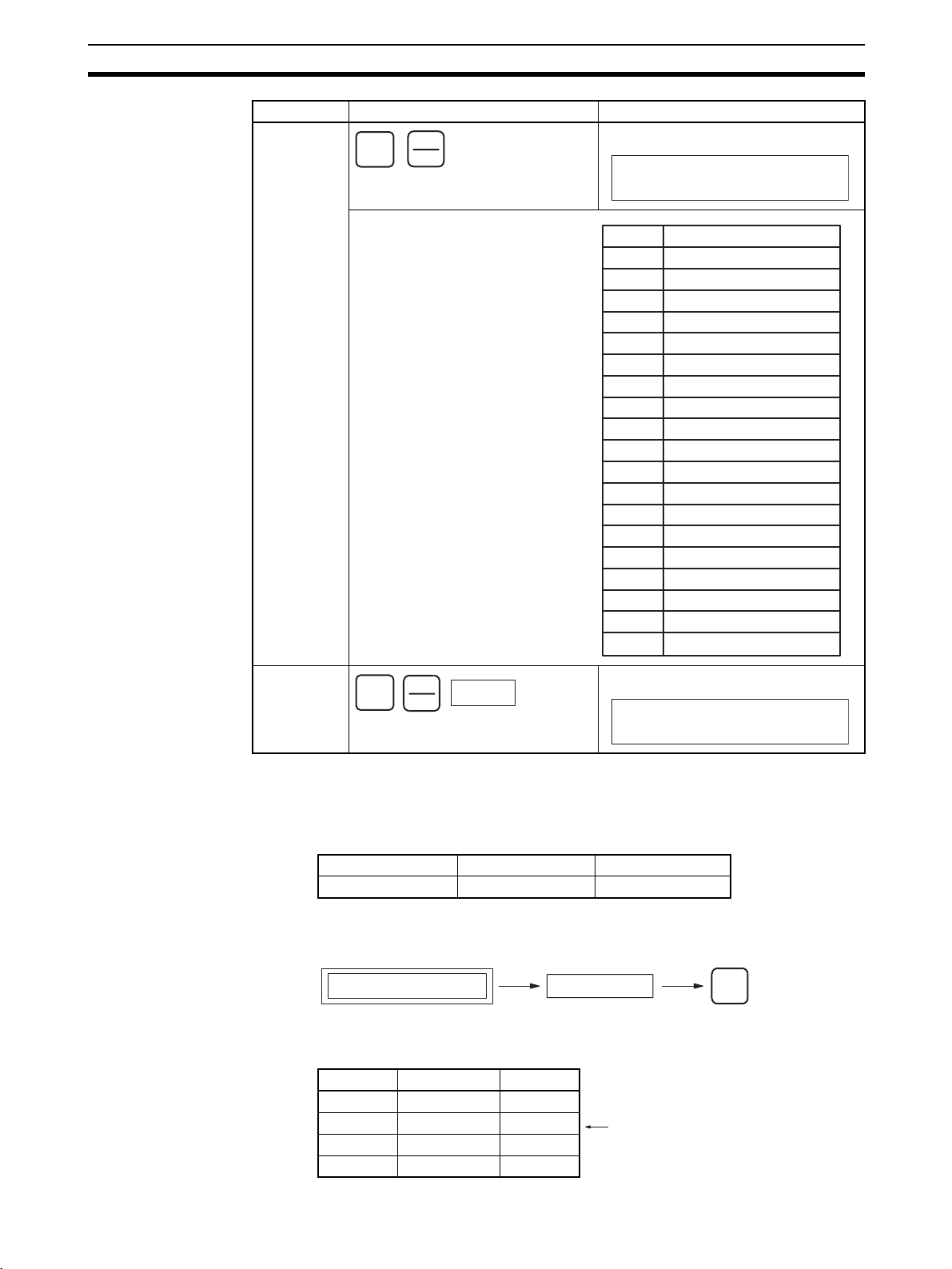
Editing Programs Section 4-3
Bit type Key sequence Display example
Clock pulse/
Condition
Flag
SHIFT
CF
SRCH
Always ON Flag
000000
BIT ON
Ta s k F l a g
When clock pulses or Condition
Flags are designated, the bits
listed at the left can be designated,
by using the Up and Down Keys.
SHIFT
TK
CNT
Number
Display Bit
ON Always ON Flag
OFF Always OFF Flag
AER Access Error Flag
0.02s 0.02-s clock pulse
0.1s 0.1-s clock pulse
0.2s 0.2-s clock pulse
1s 1-s clock pulse
1min 1-min clock pulse
ER Error Flag
CY Carry Flag
> Greater Than Flag
= Equals Flag
< Less Than Flag
N Negative Flag
OF Overflow Flag
UF Underflow Flag
>= Greater Than or Equals Flag
<> Not Equal Flag
<= Less Than or Equals Flag
TK0000
000000
BIT TK0000
4-3 Editing Programs
4-3-1 Instruction Change
RUN MONITOR PROGRAM
No No OK
This operation is used to overwrite instructions in user programs.
Key Sequence
Program address display Input mnemonic
Operation Example In the following instruction block, the instruction for address 000200 will be
changed to LD NOT 000002.
Address Instruction Operand
:::
000200 LD 000001
000201 AND 000200
:::
Changed to LD NOT 000002.
WRITE
71
Page 98

Editing Programs Section 4-3
1,2,3... 1. From the initial display, access the address where the instruction is to be
changed.
2. Input the instruction and press the WRITE Key.
3. Press the Up Key to check the instruction.
4-3-2 Instruction Insert
No No OK
This operation is used to insert instructions into the user program.
Key Sequence
Program address display Input mnemonic
CLR
000000 CT00
…
0 0
2
AA
NOT
LD
RUN MONITOR PROGRAM
2
000200 CT00
↓
LD 000001
000201 CT00
WRITE
AND 000200
000200 CT00
↑
LD N 000002
INS
Operation Example In the following instruction block, AND 000100 will be inserted at address
000201.
:::
000200 LD 000001
000201 AND 000200
:::
AND 000100 will be inserted.
1,2,3... 1. From the initial display, access the address where the instruction is to be
inserted.
CLR
000000 CT00
…
0
2
1
000201 CT00
↓
AND 000200
2. Specify the instruction to be inserted, and press the WRITE Key.
AND
0 0
1
000201 INS?
INS
AND 000100
3. Press the Down Key to insert the designated instruction. The next program
address will be displayed.
72
000202 INS END
↓
AND 000200
Page 99

Editing Programs Section 4-3
If the user attempts to insert an instruction at an address where no instruction exists, ADR OVER will be displayed, and the instruction will not be inserted.
4. Press the Up Key to check the instruction.
000201 CT00
↑
AND 000100
4-3-3 Instruction Delete
RUN MONITOR PROGRAM
No No OK
This operation is used to delete instructions from the user program.
Key Sequence
Program address display
DEL
↑
Operation Example In the following instruction block, AND 000200 will be deleted from address
00201.
Address Instruction Operand
:::
000200 LD 000001
000201 AND 000200
000202 OUT 000100
:::
Delete
1,2,3... 1. From the initial display, access the address of the instruction to be deleted.
CLR
000000 CT00
…
0
2
1
000201 CT00
↓
AND 000200
2. Delete the instruction.
000201 DEL?
DEL
AND 000200
3. Press the Up Key to delete the instruction currently displayed. The next
program address will move forward.
000201 DEL END
↑
OUT 000100
• If the user attempts to delete from an address where there is no instruction or when END(001) instruction is written, ADR OVER will be
displayed.
• When multiple-operand instructions are deleted, the set values (operands) will also be deleted.
73
Page 100

Editing Programs Section 4-3
4-3-4 Bit Address Change
RUN MONITOR PROGRAM
No No OK
This operation is used to change bit addresses in operands in the user program.
Key Sequence
Program address display
Input operand address
WRITE
Operation Example In the following instruction block, the operand address at 000200,
CIO 000001, will be changed to CIO 000002.
Address Instruction Operands
:: :
000200 LD 000001
000201 AND 000200
:: :
The operand address will be changed to
CIO 000002.
1,2,3... 1. From the initial display, access the address of the instruction containing the
bit address to be changed.
CLR
000000 CT00
…
0 0
2
000200 CT00
↓
LD 000001
2. Specify the new operand, and press the WRITE Key.
000200 CT00
2
LD 000002
3. Press the Up Key to check the operand has been changed.
4-3-5 N.O./N.C. Change
No No OK
This operation is used to change N.O. and N.C. conditions in the user program.
Key Sequence
Program address display
000201 CT00
WRITE
AND 000200
000200 CT00
↑
LD 000002
RUN MONITOR PROGRAM
NOT WRITENOT
74
 Loading...