

Page 1

Cat.No. W135–E1–3
SYSMAC
C200H-LK401/C500-LK009-V1
PC Link
SYSTEM MANUAL
Page 2

PC Link
System Manual
Revised March 2000
Page 3

Notice:
OMRON products are manufactured for use according to proper procedures by a qualified operator
and only for the purposes described in this manual.
The following conventions are used to indicate and classify precautions in this manual. Always heed
the information provided with them. Failure to heed precautions can result in injury to people or damage to property.
DANGER Indicates an imminently hazardous situation which, if not avoided, will result in death or
!
serious injury.
WARNING Indicates a potentially hazardous situation which, if not avoided, could result in death or
!
serious injury.
Caution Indicates a potentially hazardous situation which, if not avoided, may result in minor or
!
moderate injury, or property damage.
OMRON Product References
All OMRON products are capitalized in this manual. The word “Unit” is also capitalized when it refers
to an OMRON product, regardless of whether or not it appears in the proper name of the product.
The abbreviation “Ch,” which appears in some displays and on some OMRON products, often means
“word” and is abbreviated “Wd” in documentation in this sense.
The abbreviation “PC” means Programmable Controller and is not used as an abbreviation for anything else.
Visual Aids
The following headings appear in the left column of the manual to help you locate different types of
information.
OMRON, 1990
All rights reserved. No part of this publication may be reproduced, stored in a retrieval system, or transmitted, in any
form, or by any means, mechanical, electronic, photocopying, recording, or otherwise, without the prior written permission of OMRON.
No patent liability is assumed with respect to the use of the information contained herein. Moreover, because OMRON is
constantly striving to improve its high-quality products, the information contained in this manual is subject to change
without notice. Every precaution has been taken in the preparation of this manual. Nevertheless, OMRON assumes no
responsibility for errors or omissions. Neither is any liability assumed for damages resulting from the use of the information contained in this publication.
Note Indicates information of particular interest for efficient and convenient operation
of the product.
1, 2, 3... 1. Indicates lists of one sort or another, such as procedures, checklists, etc.
v
Page 4

TABLE OF CONTENTS
PRECAUTIONS xi. . . . . . . . . . . . . . . . . . . . . . . . . . . . . . . . .
1 Intended Audience xii. . . . . . . . . . . . . . . . . . . . . . . . . . . . . . . . . . . . . . . . . . . . . . . . . . . . . . . . . . .
2 General Precautions xii. . . . . . . . . . . . . . . . . . . . . . . . . . . . . . . . . . . . . . . . . . . . . . . . . . . . . . . . . .
3 Safety Precautions xii. . . . . . . . . . . . . . . . . . . . . . . . . . . . . . . . . . . . . . . . . . . . . . . . . . . . . . . . . . .
4 Operating Environment Precautions xiii. . . . . . . . . . . . . . . . . . . . . . . . . . . . . . . . . . . . . . . . . . . . .
5 Application Precautions xiii. . . . . . . . . . . . . . . . . . . . . . . . . . . . . . . . . . . . . . . . . . . . . . . . . . . . . .
SECTION 1
Introduction 1. . . . . . . . . . . . . . . . . . . . . . . . . . . . . . . . . . . .
1-1 PC Link Systems 2. . . . . . . . . . . . . . . . . . . . . . . . . . . . . . . . . . . . . . . . . . . . . . . . . . . . . . . .
1-2 Operating Levels and Polling 2. . . . . . . . . . . . . . . . . . . . . . . . . . . . . . . . . . . . . . . . . . . . . . .
SECTION 2
System Design 5. . . . . . . . . . . . . . . . . . . . . . . . . . . . . . . . . . .
2-1 System Configuration 6. . . . . . . . . . . . . . . . . . . . . . . . . . . . . . . . . . . . . . . . . . . . . . . . . . . . .
2-2 Using Link Adaptors 10. . . . . . . . . . . . . . . . . . . . . . . . . . . . . . . . . . . . . . . . . . . . . . . . . . . . .
SECTION 3
Data Exchange and Operations 11. . . . . . . . . . . . . . . . . . . .
3-1 LR Area Data 12. . . . . . . . . . . . . . . . . . . . . . . . . . . . . . . . . . . . . . . . . . . . . . . . . . . . . . . . . . .
3-2 LR Area Allocations 13. . . . . . . . . . . . . . . . . . . . . . . . . . . . . . . . . . . . . . . . . . . . . . . . . . . . .
3-3 LR Area Division Tables 17. . . . . . . . . . . . . . . . . . . . . . . . . . . . . . . . . . . . . . . . . . . . . . . . . .
3-4 Data Exchange 21. . . . . . . . . . . . . . . . . . . . . . . . . . . . . . . . . . . . . . . . . . . . . . . . . . . . . . . . . .
SECTION 4
Unit Components and Switch Settings 23. . . . . . . . . . . . . . .
4-1 C200H PC Link Units 24. . . . . . . . . . . . . . . . . . . . . . . . . . . . . . . . . . . . . . . . . . . . . . . . . . . .
4-2 C500 PC Link Units 28. . . . . . . . . . . . . . . . . . . . . . . . . . . . . . . . . . . . . . . . . . . . . . . . . . . . . .
4-3 Switch Setting Example 33. . . . . . . . . . . . . . . . . . . . . . . . . . . . . . . . . . . . . . . . . . . . . . . . . . .
SECTION 5
System Installation 37. . . . . . . . . . . . . . . . . . . . . . . . . . . . . . .
5-1 Mounting and Connections 38. . . . . . . . . . . . . . . . . . . . . . . . . . . . . . . . . . . . . . . . . . . . . . . .
5-2 Dimensions 42. . . . . . . . . . . . . . . . . . . . . . . . . . . . . . . . . . . . . . . . . . . . . . . . . . . . . . . . . . . . .
SECTION 6
Programming Considerations 45. . . . . . . . . . . . . . . . . . . . . .
6-1 Response Times 46. . . . . . . . . . . . . . . . . . . . . . . . . . . . . . . . . . . . . . . . . . . . . . . . . . . . . . . . .
6-2 Reducing Response Time (C200H, C200HS, C200HX/HG/HE(–Z)) 51. . . . . . . . . . . . . . . .
6-3 Programming Examples 52. . . . . . . . . . . . . . . . . . . . . . . . . . . . . . . . . . . . . . . . . . . . . . . . . . .
SECTION 7
Error Processing 59. . . . . . . . . . . . . . . . . . . . . . . . . . . . . . . .
7-1 SR Area Flags 60. . . . . . . . . . . . . . . . . . . . . . . . . . . . . . . . . . . . . . . . . . . . . . . . . . . . . . . . . . .
7-2 Error Examples 62. . . . . . . . . . . . . . . . . . . . . . . . . . . . . . . . . . . . . . . . . . . . . . . . . . . . . . . . . .
7-3 Error Tables 65. . . . . . . . . . . . . . . . . . . . . . . . . . . . . . . . . . . . . . . . . . . . . . . . . . . . . . . . . . . .
SECTION 8
Inspection and Maintenance 69. . . . . . . . . . . . . . . . . . . . . . .
Appendix
A Standard Models 71. . . . . . . . . . . . . . . . . . . . . . . . . . . . . . . . . . . . . . . . . . . . . . . . . . . . . . . . . . .
B Specifications 73. . . . . . . . . . . . . . . . . . . . . . . . . . . . . . . . . . . . . . . . . . . . . . . . . . . . . . . . . . . . . .
Glossary 75. . . . . . . . . . . . . . . . . . . . . . . . . . . . . . . . . . . . . . .
Index 81. . . . . . . . . . . . . . . . . . . . . . . . . . . . . . . . . . . . . . . . . .
Revision History 83. . . . . . . . . . . . . . . . . . . . . . . . . . . . . . . . .
vii
Page 5

About this Manual:
A PC Link System enables use of the LR (Link Relay) data area as a common data area shared by all PCs
in the PC Link System, thus simplifying programming, settings, and data exchange between PCs and permitting effective use of inputs and outputs.
This manual has been written to provide the information necessary to design and install a single-level or
multilevel PC Link System using PC Link Units with C500, C500F, C1000H, C2000, C2000H, C200H,
C200HS, and/or C200HX/HG/HE(-Z) PCs. Before attempting to design, install, or operate a PC Link System, be sure to thoroughly familiarize yourself with the information contained herein. During operation,
refer to the relevant PC Programming Manuals for programming and control system details.
Section 1 introduces PC Link Systems and describes their advantages and characteristics. It also
describes the improvements made in the most recent version.
Section 2 describes the elements that go together to construct a PC Link System and the factors re-
quired to design a System.
Section 3 describes the LR area used in data transfer between the PCs, the method used to allocate
it to the PCs, and the polling process used to actually transfer data.
Section 4 provides details on PC Link Units, the main Units used to build PC Link Systems. Parts of
the Units, switch setting, and examples of switch settings are provided.
Section 5 provides details on mounting and wiring PC Link Units and provides Unit dimensions.
Section 6 offers details and examples of programming PCs to utilize PC Link Systems effectively.
Section 7 describes error indications and error processing. Both indicator lights and dedicated error-
related flags are provided.
Section 8 describes basic maintenance and hardware troubleshooting procedures.
Appendix A provides basic specifications and complete model numbers for OMRON products used
in PC Link Systems.
Appendix B provides general specifications for PC Link Units and PC Link Systems.
This manual is intended to be used in conjunction with the PC Operation Manual and/or Installation
Guides for the PCs in the System. In most Systems, the Link Adaptor Operation Guide will also be
required. The application of Link Adaptors to PC Link Systems is also described in this manual.
This manual is designed for the C500-LK009-V1 and C200H-LK401 PC Link Units. These are sometimes referred to as the LK009-V1 and LK401. The older 3G2A5-LK003-E and 3G2A5-LK009-E PC
Link Units are mentioned only to allow combination with the newer models, and are not discussed in
detail.
!
WARNING Failure to read and understand the information provided in this manual may result in
personal injury or death, damage to the product, or product failure. Please read each
section in its entirety and be sure you understand the information provided in the section
and related sections before attempting any of the procedures or operations given.
ix
Page 6

PRECAUTIONS
This section provides general precautions for using the Programmable Controller (PC) and related devices.
The information contained in this section is important for the safe and reliable application of the PC. You must read
this section and understand the information contained before attempting to set up or operate a PC system.
1 Intended Audience xii. . . . . . . . . . . . . . . . . . . . . . . . . . . . . . . . . . . . . . . . . . . . . . . . . . . . . . . . . . . .
2 General Precautions xii. . . . . . . . . . . . . . . . . . . . . . . . . . . . . . . . . . . . . . . . . . . . . . . . . . . . . . . . . . .
3 Safety Precautions xii. . . . . . . . . . . . . . . . . . . . . . . . . . . . . . . . . . . . . . . . . . . . . . . . . . . . . . . . . . . .
4 Operating Environment Precautions xiii. . . . . . . . . . . . . . . . . . . . . . . . . . . . . . . . . . . . . . . . . . . . . .
5 Application Precautions xiii. . . . . . . . . . . . . . . . . . . . . . . . . . . . . . . . . . . . . . . . . . . . . . . . . . . . . . . .
xi
Page 7

1 Intended Audience
This manual is intended for the following personnel, who must also have knowledge of electrical systems (an electrical engineer or the equivalent).
• Personnel in charge of installing FA systems.
• Personnel in charge of designing FA systems.
• Personnel in charge of managing FA systems and facilities.
2 General Precautions
The user must operate the product according to the performance specifications
described in the operation manuals.
Before using the product under conditions which are not described in the manual
or applying the product to nuclear control systems, railroad systems, aviation
systems, vehicles, combustion systems, medical equipment, amusement
machines, safety equipment, and other systems, machines, and equipment that
may have a serious influence on lives and property if used improperly, consult
your OMRON representative.
Make sure that the ratings and performance characteristics of the product are
sufficient for the systems, machines, and equipment, and be sure to provide the
systems, machines, and equipment with double safety mechanisms.
This manual provides information for programming and operating OMRON PCs.
Be sure to read this manual before attempting to use the software and keep this
manual close at hand for reference during operation.
3Safety Precautions
WARNING It is extreme important that a PC and all PC Units be used for the specified
!
purpose and under the specified conditions, especially in applications that can
directly or indirectly affect human life. You must consult with your OMRON
representative before applying a PC System to the abovementioned
applications.
3 Safety Precautions
WARNING Do not attempt to take any Unit apart while the power is being supplied. Doing so
!
may result in electric shock.
WARNING Do not touch any of the terminals or terminal blocks while the power is being
!
supplied. Doing so may result in electric shock.
WARNING Do not attempt to disassemble, repair, or modify any Units. Any attempt to do so
!
may result in malfunction, fire, or electric shock.
xii
Page 8

4 Operating Environment Precautions
Caution Do not operate the control system in the following locations:
!
• Locations subject to direct sunlight.
• Locations subject to temperatures or humidity outside the range specified in
the specifications.
• Locations subject to condensation as the result of severe changes in temperature.
• Locations subject to corrosive or flammable gases.
• Locations subject to dust (especially iron dust) or salts.
• Locations subject to exposure to water, oil, or chemicals.
• Locations subject to shock or vibration.
Caution Take appropriate and sufficient countermeasures when installing systems in the
!
following locations:
• Locations subject to static electricity or other forms of noise.
• Locations subject to strong electromagnetic fields.
• Locations subject to possible exposure to radioactivity.
• Locations close to power supplies.
5Application Precautions
Caution The operating environment of the PC system can have a large effect on the lon-
!
gevity and reliability of the system. Improper operating environments can lead to
malfunction, failure, and other unforeseeable problems with the PC system. Be
sure that the operating environment is within the specified conditions at installation and remains within the specified conditions during the life of the system.
5 Application Precautions
Observe the following precautions when using the PC system.
WARNING Always heed these precautions. Failure to abide by the following precautions
!
could lead to serious or possibly fatal injury.
• Always ground the system to 100 Ω or less when installing the Units. Not connecting to a ground of 100 Ω or less may result in electric shock.
• Always turn OFF the power supply to the PC before attempting any of the following. Not turning OFF the power supply may result in malfunction or electric
shock.
• Mounting or dismounting I/O Units, CPU Units, Memory Units, or any other
Units.
• Assembling the Units.
• Setting DIP switches or rotary switches.
• Connecting cables or wiring the system.
• Connecting or disconnecting the connectors.
Caution Failure to abide by the following precautions could lead to faulty operation of the
!
PC or the system, or could damage the PC or PC Units. Always heed these precautions.
• Fail-safe measures must be taken by the customer to ensure safety in the
event of incorrect, missing, or abnormal signals caused by broken signal lines,
momentary power interruptions, or other causes.
xiii
Page 9

• Always use the power supply voltages specified in this manual. An incorrect
voltage may result in malfunction or burning.
• Take appropriate measures to ensure that the specified power with the rated
voltage and frequency is supplied. Be particularly careful in places where the
power supply is unstable. An incorrect power supply may result in malfunction.
• Install external breakers and take other safety measures against short-circuiting in external wiring. Insufficient safety measures against short-circuiting may
result in burning.
• Do not apply voltages to the Input Units in excess of the rated input voltage.
Excess voltages may result in burning.
• Do not apply voltages or connect loads to the Output Units in excess of the
maximum switching capacity. Excess voltage or loads may result in burning.
• Disconnect the functional ground terminal when performing withstand voltage
tests. Not disconnecting the functional ground terminal may result in burning.
• Be sure that all the mounting screws, terminal screws, and cable connector
screws are tightened to the torque specified in this manual. Incorrect tightening torque may result in malfunction.
• Leave the label attached to the Unit when wiring. Removing the label may result in malfunction if foreign matter enters the Unit.
• Remove the label after the completion of wiring to ensure proper heat dissipation. Leaving the label attached may result in malfunction.
• Double-check all wiring and switch settings before turning ON the power supply. Incorrect wiring may result in burning.
• Wire correctly. Incorrect wiring may result in burning.
• Mount Units only after checking terminal blocks and connectors completely.
• Be sure that the terminal blocks, Memory Units, expansion cables, and other
items with locking devices are properly locked into place. Improper locking
may result in malfunction.
• Check the user program for proper execution before actually running it on the
Unit. Not checking the program may result in an unexpected operation.
• Confirm that no adverse effect will occur in the system before attempting any of
the following. Not doing so may result in an unexpected operation.
• Changing the operating mode of the PC.
• Force-setting/force-resetting any bit in memory.
• Changing the present value of any word or any set value in memory.
• Resume operation only after transferring to the new CPU Unit the contents of
the DM Area, HR Area, and other data required for resuming operation. Not
doing so may result in an unexpected operation.
• Do not pull on the cables or bend the cables beyond their natural limit. Doing
either of these may break the cables.
• Do not place objects on top of the cables or other wiring lines. Doing so may
break the cables.
• Use crimp terminals for wiring. Do not connect bare stranded wires directly to
terminals. Connection of bare stranded wires may result in burning.
• When replacing parts, be sure to confirm that the rating of a new part is correct.
Not doing so may result in malfunction or burning.
• Before touching a Unit, be sure to first touch a grounded metallic object in order
to discharge any static built-up. Not doing so may result in malfunction or damage.
5Safety Precautions
xiv
Page 10

SECTION 1
Introduction
1-1 PC Link Systems 2. . . . . . . . . . . . . . . . . . . . . . . . . . . . . . . . . . . . . . . . . . . . . . . . . . . . . . . . .
1-2 Operating Levels and Polling 2. . . . . . . . . . . . . . . . . . . . . . . . . . . . . . . . . . . . . . . . . . . . . . . .
1
Page 11

Operating Levels and Polling Section 1-2
1-1 PC Link Systems
A PC Link System is established to interconnect two or more C-series PCs
through PC Link Units to allow data transfer through the LR area of each PC.
PC Link Subsystems can be established within the PC Link System, creating
different levels of operation. Each PC in the PC Link System automatically
exchanges data with all the PCs in the same Subsystem. Any PC in two Subsystems (i.e., any PC to which two PC Link Units are mounted) can be used
as a “transfer PC” to transfer data between two PC Link Subsystems.
The data communications provided by PC Link Systems allow use of the inputs and outputs on all of the PCs in the System in the program of any PC.
PC Link Systems do not establish hierarchies of control between PCs. i.e., all
control actions must be written in the programs of individual PCs.
Compared with I/O Links
Effective I/O Utilization
Simplified System Setup
Subsystem Data Exchange
LK009-V1 Improvements
PC Link Systems exchange data differently to I/O Links in Optical Remote I/O
Systems in three main ways. First, an I/O Link requires the use of I/O points,
reducing the number of I/O points available to connect to I/O devices. Second, the number of bits transferred between PCs in a PC Link System is limited only by the size of the LR area and the number of PCs in the PC Link
System; an I/O Link in a Remote Optical System can handle only one or two
words. Third, I/O Links use programmed input and output operations to transfer data, whereas PC Link Systems use an automatic polling method.
PC Link Systems access only the LR area of the PC for data exchange and
do not require the use of any of the PCs I/O points.
Settings on the PC Link Units allow for data exchange little or no programming required.
Two PC Link Subsystems operating at different levels can exchange data via
the LR area of a PC operating in both Subsystems.
The C500-LK009-V1 differs from the 3G2A5-LK009 in insulation of the transmission section from the internal circuits to improve anti-noise performance.
This increased performance reduces noise interfere originating in ground differences, cable inductance, etc. The C500-LK009-V1 can also be used together with the C200H-LK401. This is not possible with the 3G2A5-LK009.
LK003-E PC Link Units
Although not covered in detail in this manual, the LK003-E PC Link Unit can
be used in PC Link Systems together with the LK009-V1 PC Link Unit. If the
LK003-E is used, the PC Link System must be single-level and all LK009-V1
PC Link Units in the System must be set to LK003-E mode. The LK003-E (or
an LK009-V1 in LK003-E mode) can be used only on C500 PCs and cannot
be used in the same PC Link System as a C200H-LK401 PC Link Unit.
1-2 Operating Levels and Polling
All PC Link Units are assigned unit numbers which determine what part of
the LR area each is to be allocated. Whenever two or more PCs are connected in a PC Link System, one of the PC Link Units must be set as the polling unit (i.e., as Unit #0) and all other PC Link Units must be set as polled
units (i.e., as any Unit other than #0). The polling unit of each PC Link Subsystem does not control the other PCs, which are each controlled independently by their own CPUs.
2
Page 12
Operating Levels and Polling Section 1-2
A maximum of two PC Link Units can be mounted to the same PC. If two PC
Link Units are mounted to one PC anywhere in the System, the System is
multilevel, and all Units must be set for a Multilevel System (see 4-2-2 Switch
Settings). In a Multilevel System, operating levels must be set to create PC
Link Subsystems. Each Subsystem will have its own polling unit.
Up to four Subsystems are possible. There will always be one more Subsystem than there are PCs to which two PC Link Units are mounted. Only operating levels 0 and 1 are set, as it is necessary only to differentiate between
two PC Link Units on the same PC. All of the PC Link Unit in the same Subsystem must be set to the same level.
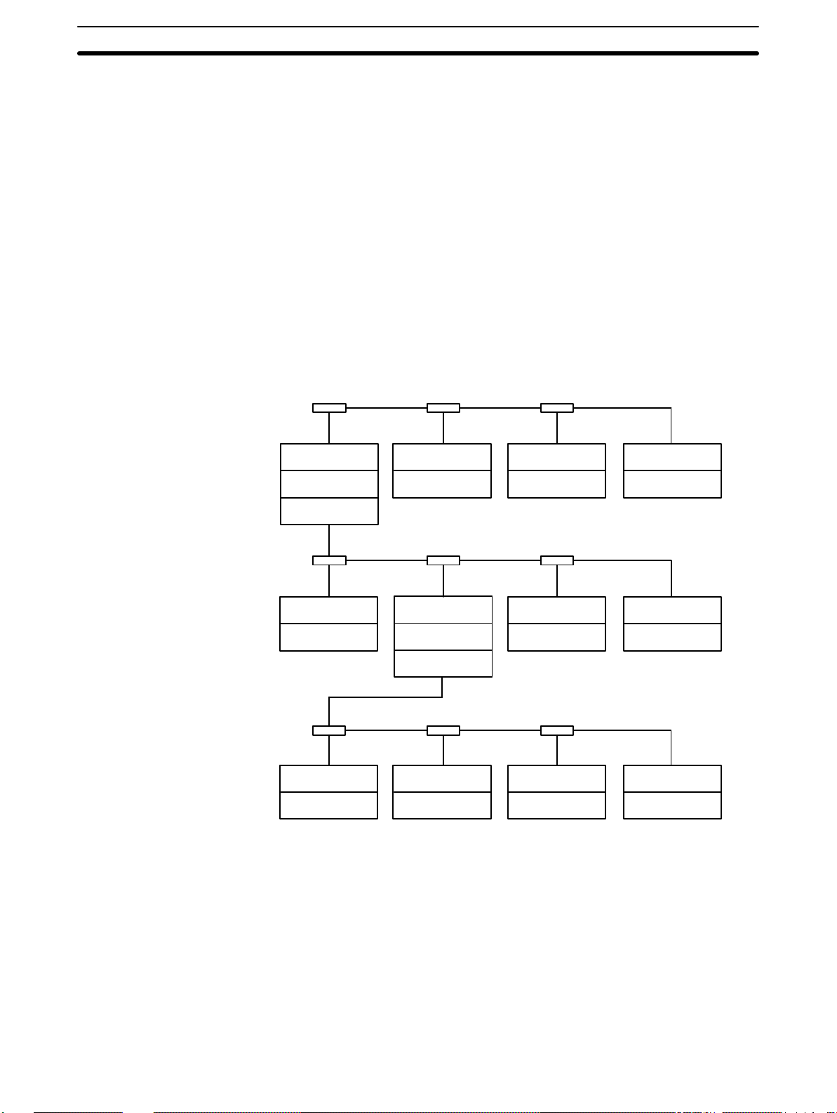
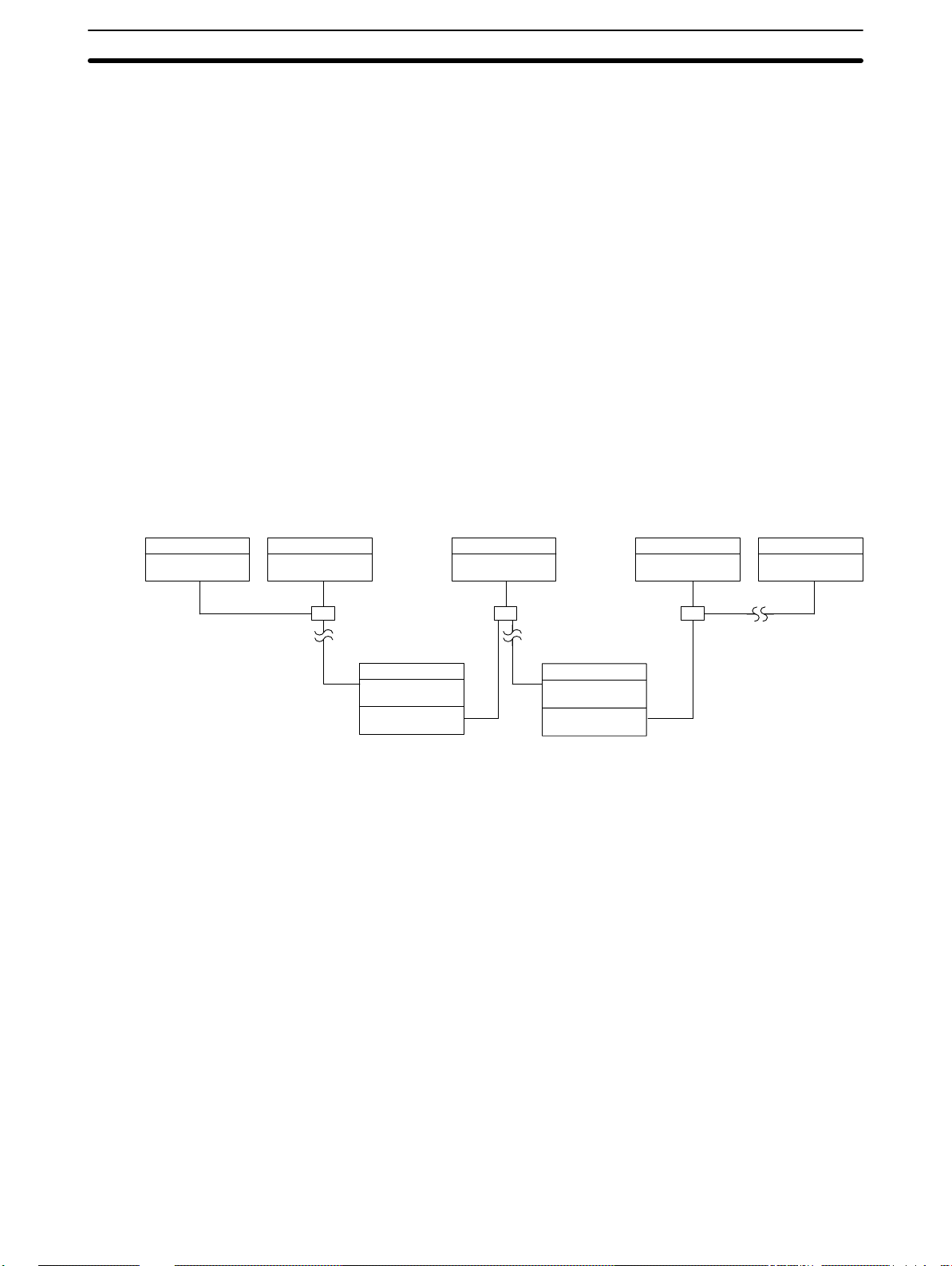
A PC Link System with three Subsystems is shown below. Any one of the PC
Link Units in any Subsystem may be designated as the polling unit. All other
Units would be polled units. The small boxes shown connecting the PC Link
Units are Link Adapters, which are used to connect PC Link Units when more
than two are used in a Subsystem. See following sections for details on System design and Link Adapters. (The 3G2A5-LK003-E PC Link Unit cannot be
used in Multilevel Systems.)
PC Link Unit
PC
PC Link Unit
PC Link Unit
PC
PC Link Unit
PC
PC Link Unit
PC
PC Link Unit
PC
PC Link Unit
PC Link Unit
PC
PC Link Unit
PC
PC Link Unit
PC
PC Link Unit
PC
PC Link Unit
PC
PC Link Unit
PC
PC Link Unit
PC
3
Page 13

SECTION 2
System Design
2-1 System Configuration 6. . . . . . . . . . . . . . . . . . . . . . . . . . . . . . . . . . . . . . . . . . . . . . . . . . . . . .
2-2 Using Link Adaptors 10. . . . . . . . . . . . . . . . . . . . . . . . . . . . . . . . . . . . . . . . . . . . . . . . . . . . . .
5
Page 14
System Configuration Section 2-1
2-1 System Configuration
PC Link Units are mounted to the PC Racks and connected to each other.
Each PC Link Unit contains a buffer through which data is transferred to and
from the other PC Link Units connected to it. The C500-LK009-V1 can be
used with C500, C1000H, and C2000H PCs, but not with a C200H, C200HS,
or C200HX/HG/HE(-Z) PC. The C200H-LK401 can be used with C200H,
C200HS, and C200HX/HG/HE(-Z) PCs.
Link Adaptors are used in any System other than one containing only two
PC Link Units connected with wire cable. They serve as branching points to
enable connecting more than two PC Link Units, which provide only one connector each allowing only two PC Link Units to be connected directly, or they
serve as conversion points to change between wire and optical fiber
cables.The 3G2A9-AL001 Link Adapter is used as the Branching Link Adapter (see Example 3, below), and combinations of the 3G2A9-AL004 and
3G2A9-AL002 Link Adapters are used to convert to and from optical fiber
cable.Refer to the Link Adapter Installation Guide for Link Adapter specifications and details.
Multilink Systems
Multilevel Systems
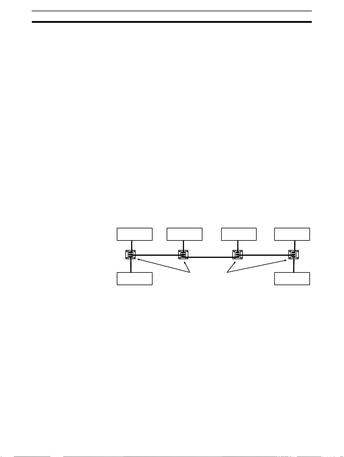
Each PC Link Unit has only one connector, making it impossible to connect
more than two PC Link Units directly. Many more PCs can become part of
the same PC Link System however, if Branching Link Adapters are used to
connect through. A PC Link System including six PCs is illustrated below to
show this. This arrangement also protects PC Link communications from
shutting down completely for failures in the line, i.e., if communications are
broken off on a branch line, data transfer will continue to PCs still connected
though PC Link Units to the polling unit.
PC with PC
Link Unit
PC with PC
Link Unit
PC with PC
Link Unit
Link Adapters
PC with PC
Link Unit
PC with PC
Link Unit
PC with PC
Link Unit
Up to two PC Link Units can be mounted to one PC. Any PC with two PC
Link Units mounted to it or any PC part of a PC Link System that contains
such a PC is in a Multilevel PC Link System. If any one PC in the PC Link
System has two PC Link Units mounted to it, the entire System is multilevel.
Each group of PCs connected by PC Link Units and sharing parts of the LR
area are part of the same PC Link Subsystem. If a PC has two PC Link
Units mounted to it, it is part of two PC Link Subsystems, with each Subsystem extending from a PC with two PC Link Units to either the end PC or the
next PC with two PC Link Units (see diagram below).
Each Subsystem will have its own polling unit. Each Subsystem is also assigned an operating level to differentiate the two Subsystems to which one
PC belongs. These operating levels do not imply a hierarchy or in anyway
affect operation of the Subsystems except to determine which LR words are
allocated to which Subsystem (see next subsection for details).
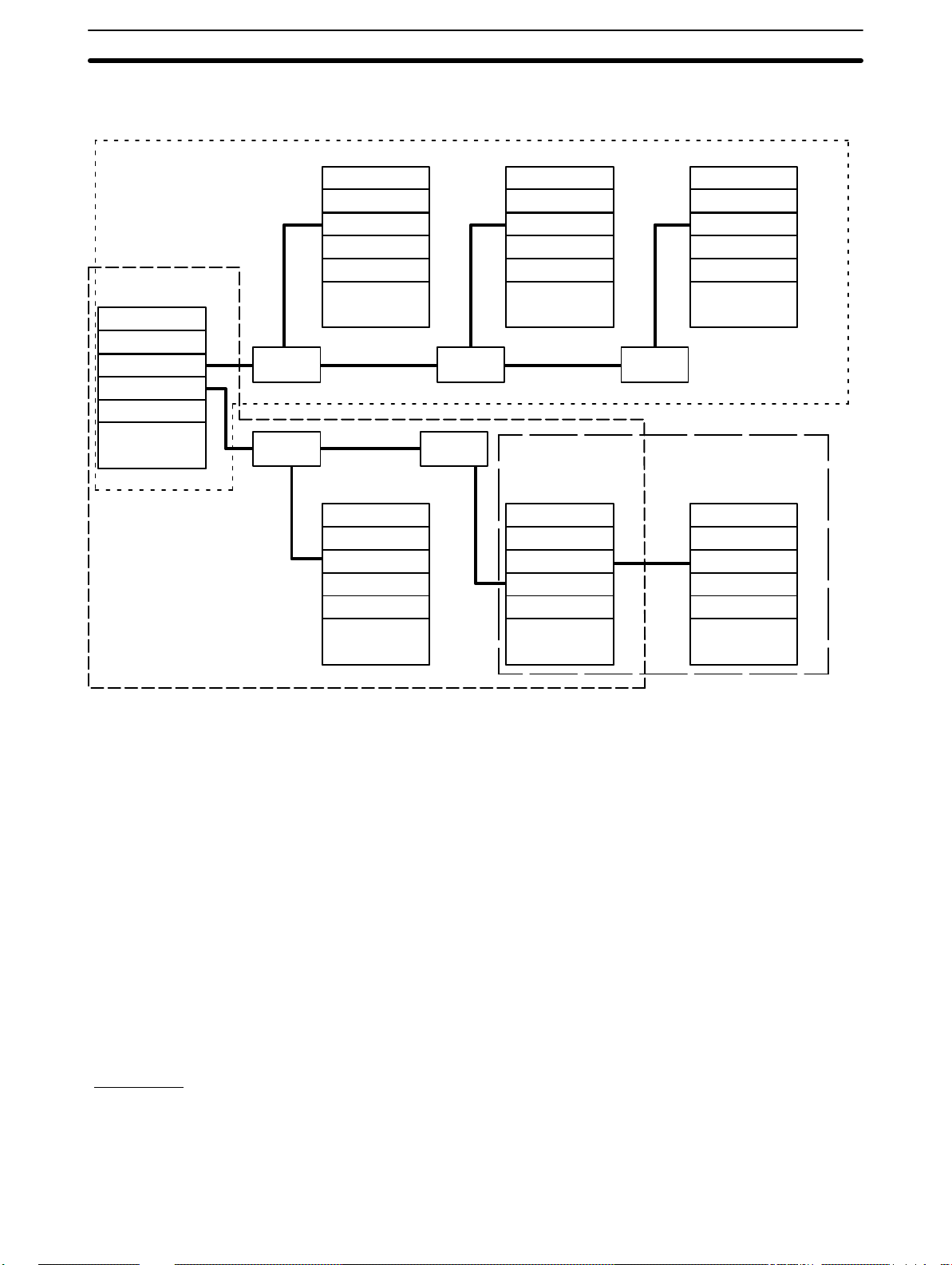
The following example conceptually shows a Multilevel PC Link System with
three Subsystems. Although Subsystems 1 and 3 are assigned the same
operating level, they are not related in any special way.
6
Page 15
System Configuration Section 2-1
Note that a Link Adapter is not used in Subsystem 3. As explained above, it
does not require any because it contains only two PCs.
Subsystem 1
operating level 1
CPU Rack
PC Link Unit
PC Link Unit
CPU
Link
Adapter
Link
Adapter
CPU Rack
PC Link Unit
CPU
CPU Rack
PC Link Unit
Link
Adapter
Link
Adapter
CPU Rack
PC Link Unit
CPU
CPU Rack
PC Link Unit
PC Link Unit
CPU Rack
PC Link Unit
CPU
Link
Adapter
Subsystem 3
operating level 1
CPU Rack
PC Link Unit
Subsystem 2
operating level 0
Transfer PCs
Transmission Distance
Examples
CPU
CPU
CPU
A PC that has two PC Link Units mounted to it is called a transfer PC. This is
because it can be used to transfer data between the two PC Link Subsystems to which it belongs.
Although all the PCs in the same Subsystem automatically have data written
into their LR areas from the PCs in the same Subsystem, this is not the case
with PCs in different Subsystems. A PC that belongs to two Subsystems can,
however, transfer data between Subsystems by reading it from any part of
the LR words it shares with one of the Subsystems and writing the data to
the words allocated it in the other Subsystem. This transfer operation is programmed by the user in the normal user program.
The total length of wire cable (e.g., RS-485 or RS-422) must not exceed 500
m. Individual branch lines from Link Adapters to PC Link Units must not exceed 10 m. Greater transmission distances can be achieved by using optical
links between PC Link Units (see Section 2 Link Adapters).
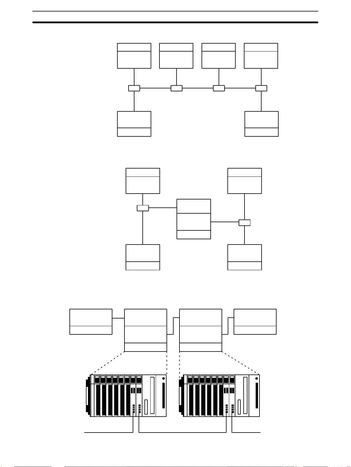
The following examples demonstrate some of the ways that PCs can be connected in PC Link Systems. Example 3 also provides the appearance two of
the CPU Racks in the System.
An example of a PC Link System designed using optical links is provided in
2-2 Using Link Adapters.
7
Page 16
System Configuration Section 2-1
Example 1
Single-level System
C-series PC
C-series PC
C-series PC
C-series PC
Example 2
Two-level System
Polled PC
Link Unit
Link
Adaptor
Polled PC
Link Unit
C-series PC
C-series PC C-series PC
Polled PC
Link Unit
Link
Adapter
Polled PC
Link Unit
C-series PC
Link
Adaptor
Polling PC
Link Unit
Polled PC
Link Unit
Polled PC
Link Unit
Link
Adaptor
Polling PC
C-series PC
Polling PC
Link Unit
Link Unit
Polled PC
Link Unit
Link
Adapter
Link
Adaptor
Example 3
Three-level System
Polled PC
Link Unit
C-series PC
Polled PC
Link Unit
Polling PC
Link Unit
Polling PC
Link Unit
C-series PC
C500 CPU Rack
Polled PC
Link Unit
Polling PC
Link Unit
C-series PC
C500 CPU Rack
Polled PC
Link Unit
C-series PCC-series PC
Polled PC
C-series PC
Link Unit
8
Page 17
System Configuration Section 2-1
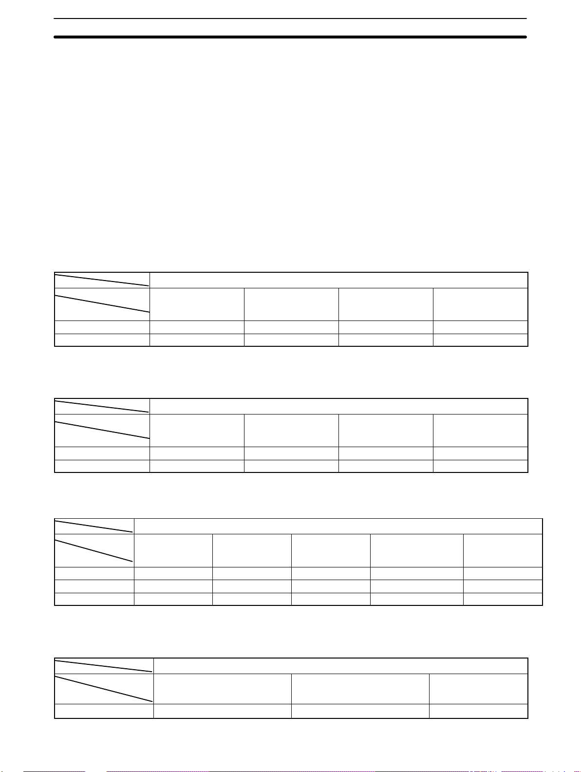
System Limitations
The maximum number of PCs that may be used in a PC Link System is limited by the number of LR words available. This is determined by the number
of levels, the specific PCs employed, and the mode settings on the PC Link
Units.
A PC Link Unit must be assigned a number no greater than one less than the
maximum number of allowable PCs to be acknowledge as part of the System. A PC Link Unit assigned a number greater than this limit will not be acknowledged. The maximum number of Units available in a specific PC Link
System is described in the following tables.
Only the PC Link Unit combinations shown below are possible. Note particularly that the LK003-E (or LK009-V1 in LK003-E mode) can only be used with
other LK003-E PC Link Units (or LK009-V1 in LK003-E mode).
Polling Unit: C200H-LK401 PC Link Unit on C200H, C200HS, or C200HX/HG/HE(-Z) PC
Polled units
LK401 on
C200H, C200HS, or
C200HX/HG/HE(-Z)
Multilevel 16 8 16 16
Single-level 32 8 32 32
LK009-V1 on C500
LK009-V1 on C1000H
or C2000H
Max. total
Polling Unit: C500-LK009-V1 PC Link Unit on C1000H or C2000H PC
Polled units
LK009-V1 on C1000H
or C2000H
Multilevel 16 8 16 16
Single-level 32 8 32 32
LK009-V1 on C500
LK401 on
C200H, C200HS, or
C200HX/HG/HE(-Z)
Max. total
Polling Unit: C500-LK009-V1 PC Link Unit on C500 PC
Polled units
LK009-V1 on
C1000H or
C2000H
Multilevel 8 8 Not possible 8 8
Single-level 8 8 Not possible. 8 8
LK003-E mode Not possible 8 8 Not possible. 8
LK009-V1 on
C500
LK003-E on C500
LK401 on
C200H, C200HS, or
C200HX/HG/HE(-Z)
Polling Unit: 3G2A5-LK003-E PC Link Unit on C500 PC
Max. total
Polled units
LK009-V1 on C500 in LK003-E
mode
Single-level 8 8 8
LK003-E on C500 Max. total
9
Page 18

Using Link Adaptors Section 2-2
2-2 Using Link Adaptors
In a PC Link System, Link Adapters are used whenever more than two PC
Link Units are connected in any one PC Link Subsystem. They are also used
to enable optical links between PC Link Units to provide greater transmission
distance and greater noise resistance. When using Link Adaptors, refer to
the Link Adaptor Installation Guide.
Optical Cable in PC Link
Systems
PC Link Unit
C-series PC
A PC Link System can be set up to take advantage of optical communications by using combinations of Branching and Converting Link Adapters. As
shown below, each PC Link Unit is connected to a Converting Link Adapter
that converts to optical communications. Optical fiber cable is then used to
form the main line and branch lines that connect each PC Link Unit-Converting Link Adapter pair.
The straight lines in the following diagram represent wire cables; those with
zig-zags in them, optical fiber cable.
In the following example, any of the PC Link Units may be set as the polling
unit.
AL004 Link
Adapter
Optical fiber
AL002 Link
Adapter
AL004 Link
Adapter
PC Link Unit
AL002 Link
Adapter
PC Link Unit
AL004 Link
Adapter
AL004 Link
Adapter
PC Link Unit
C-series PC
Handling Optical Fiber
Cable
C-series PC
C-series PC
Although special characteristics of optical fibers call for care in connecting
optical devices, laying optical fiber cable basically does not differ from laying
wire cable. All OMRON PCF and the 3G5A2-PF101 APF (length: 1 m) cable
come with connectors attached. Connectors for all other APF cables must be
assembled by the customer. As using Optical Fiber cable requires the use of
Link Adaptors, refer to the Link Adaptor Installation Guide for more detailed
information.
10
Page 19

SECTION 3
Data Exchange and Operations
3-1 LR Area Data 12. . . . . . . . . . . . . . . . . . . . . . . . . . . . . . . . . . . . . . . . . . . . . . . . . . . . . . . . . . . .
3-2 LR Area Allocations 13. . . . . . . . . . . . . . . . . . . . . . . . . . . . . . . . . . . . . . . . . . . . . . . . . . . . . . .
3-3 LR Area Division Tables 17. . . . . . . . . . . . . . . . . . . . . . . . . . . . . . . . . . . . . . . . . . . . . . . . . . .
3-4 Data Exchange 21. . . . . . . . . . . . . . . . . . . . . . . . . . . . . . . . . . . . . . . . . . . . . . . . . . . . . . . . . . .
11
Page 20

LR Area Data Section 3-1
3-1 LR Area Data
PC Link Systems employ the LR area in the exchange of data. The content
of the LR areas in all PCs in the same PC Link Subsystem (or Single-level
System) is kept consistent. To achieve this, the LR area is divided among all
of the PCs in the Subsystem according to switch settings, and each PC
writes data only to the part of the LR area allocated to it. When a PC writes to
its LR area, the data is updated in the LR areas of all the other PCs in the PC
Link Subsystem during the next polling cycle. The other PCs can then read
this data and use it to coordinate activities with the PC that has written the
data. Each PC thus writes data to its write words and reads data from the
words written to by all of the other PC Link Units in the same Subsystem. Any
action that affects the contents of the LR area is reflected in the LR area in all
PCs. The data transfer is shown below in a Single-level System. Arrows indicate data flow within the PC Link System.
“Write area” is the area written by that Unit. ”Read area” is an area read by
that Unit (i.e., written by another Unit). All unused portions of the LR area
may be used as work bits in programming.
Read
area
Read
area
Read
area
Data Data Data
Data Data Data
Data Data Data
Data Data Data
Read
area
Read
area
Read
area
Read
area
Read
area
Read
area
Read
area
Read
area
Read
area
What determines what part of the LR area is allocated to which PC is the unit
number assigned to each PC Link Unit. These numbers in turn determine which
PC Link Units are polling units and which are polled units.
When PC Link Unit 0 is set for the total number of LR bits used, and each of
the PC Link Units is assigned a unit number, the LR area is divided and assigned to each PC Link Unit automatically.
In a Multilevel System, all PCs have their LR areas divided in half, with one
half being assigned to each of two Subsystems. This is true regardless of
whether or not the PC is actually in two Subsystems, i.e., if only one PC Link
Unit is mounted to a PC in a Multilevel System, one have of the LR area is
not used by the PC Link System.
12
Each PC in two Subsystems (i.e.,with two PC Link Units mounted to it) thus
contains all the LR area data from both Subsystems and has a write data
area in assigned to each. Any PC with only one PC Link Unit contains only
the LR area data for the Subsystem it is in. The LR area of any PC with two
PC Link Units (i.e., the data-transfer PCs) can thus be used to transfer data
between two Subsystems by programming the data-transfer PC to move data
between its section of the first half and its section of the last half of its LR
area. See Section 6 Application Examples for specific LR area allocation examples for both Single-level and Multilevel Systems.
Page 21

LR Area Allocations Section 3-2
3-2 LR Area Allocations
To enable data transfer between PCs in an PC Link System, part of the LR
area is allocated as the write area for each PC in the System. Which and how
many LR words are allocated to each PC are determined by switch settings,
which are described in 4-2-2 Switch Settings. This section describes the
method for allocating words assuming that each PC is allocated the maximum number of words possible.
LR Area Allocation in
Mixed-PC Systems
If a System contains PCs that have different sizes of LR areas, only the
words that are common to both areas are used in actual PC Link communications. In the following example, the LR areas of each PC are illustrated
below it. Words labeled “work words” are not used by the PC Link System
and are available for use in programming if required. As shown, the rest of
the LR area is divided with the smaller LR area of the other PC to form the
write words for each.
C1000H CPU Rack C500 CPU Rack
PC Link Units
C1000H CPU C500 CPU
LR 00 to LR 15
LR 08 to LR 15
LR 16 to LR 31 LR 16 to LR 31
LR 00 to LR 15
Single-level System
LR 32 to LR 63
Work words
The following example combines one C2000H PC, two C500 PCs, and a
C200H PC in a Single-level System using 128 LR bits per PC. The PC Link
Unit on the C2000H PC at the left end of the System has been designated as
the polling unit. The C500 PCs, providing the smallest LR areas, limit the
number of bits that can be transferred via the PC Link Units. Because the
C500 PC has only 32 words, only words 00 through 31 may be used in the
C2000H PCs (Units #0 and #2). The C2000H and C200H LR words that are
not used (32 to 63) may be used as work bits in programming. The LR word
allocations for each PC Link Unit are given below it. The shaded area is the
section of the LR area written to by the PC Link Unit. The arrows indicate
data flow.
In this example, data written to words LR 8 through 15 by the PC to which PC
Link Unit 2 is mounted is automatically transmitted to words LR 8 through 15
in the other PCs. While the PCs for PC Link Units #0, #1, and #3 are able to
read this data freely, they cannot write in this area. All of the other PCs also
13
Page 22

LR Area Allocations Section 3-2
are assigned the word shaded below them which they write and can be written by the other PCs.
C500 CPU Rack C500 CPU Rack
PC Link Unit 0
C2000H CPU Rack
C200H CPU Rack
PC Link Unit 1
C2000H CPU
Unit 0
LR 00 to LR 07
LR 00 to LR 07
LR 08 to LR 15
LR 08 to LR 15
LR 16 to LR 23
LR 16 to LR 23
LR 24 to LR 31
LR 24 to LR 31
Useable
LR 32 to LR 63 LR 32 to LR 63
as work
bits
C500 CPU
Unit 1
LR 00 to LR 07
LR 08 to LR 15
LR 16 to LR 23
LR 24 to LR 31
The C200H could be replaced by the C200HS and C200HX/HG/HE(-Z) with-
Note
PC Link Unit 2
C500 CPU
Unit 2
LR 00 to LR 07
LR 08 to LR 15
LR 16 to LR 23
LR 24 to LR 31
PC Link Unit 3
Useable
as work
bits
C200H CPU
Unit 3
LR 00 to LR 07
LR 08 to LR 15
LR 16 to LR 23
LR 24 to LR 31
out any changes in this example.
LR Area Allocations in
Multilevel Systems
In a Multilevel PC Link System, only half of the LR area in each PC is used
for communications in any one PC Link Subsystem. The first half of the
words (from word 00) is used by the Subsystem assigned operating level 0;
the second half, by the Subsystem assigned operating level 1. This is true
regardless of whether or not a PC is actually in two Subsystems. In the example on the next page, the two C500s do not use LR words 16 through 31
because they are not in a Subsystem in operating level 1. If another PC Link
Unit was later added to either PC, these words would be available for use by
it. The number of words used by a Subsystem is thus half of the number of
words provided by the PC with the smallest LR area.
Once the words used in a Subsystem are determined, the process is the same
as for any other PC Link System: words common to all of the PCs in a Subsystem
are divided evenly among the PC Link Units, with unit numbers determining
which words are allocated to which Unit. Again, the Unit assigned number 0 in
each Subsystem is the polling unit for that Subsystem.
14
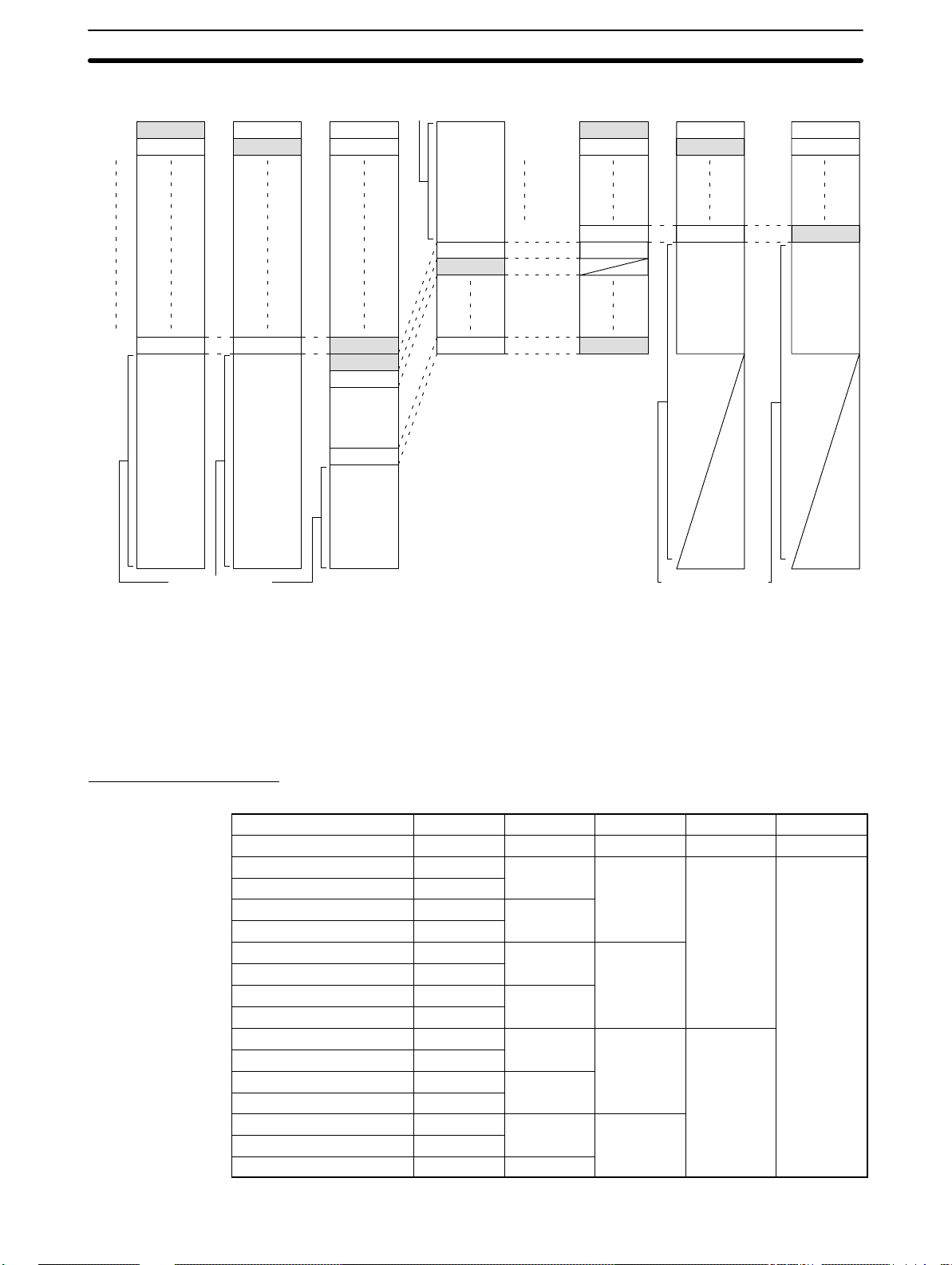
Below are provided the system configuration, unit numbers, operating levels,
and word allocations for each PC Link Unit in a Multilevel System. The vertical
bars represent the LR area in each PC. Arrows indicate data flow from the words
written to by each PC. Write words for each PC have been shaded.
In the Subsystem assigned operating level 1, LR words 56 through 63 are not
used for PC Link communications because switch settings are available only for
2, 4, 8, or 16 PC Link Units per Subsystem. If a fourth PC was added to this Subsystem, it would be assigned these words.
Although not used by the PC Link System, words labeled “not used” may be
used as work words in programming to manipulate data within the CPU.
Page 23

LR Area Allocations Section 3-2
In the example below, the C2000H PC would be a transfer PC and could be used
to transfer data between the two Subsystems, e.g., to write to LR word12 by the
C200H PC in operating level 0 to LR word 32, one of its write words in operating
level 1. Any PC in level 1 could then access this data directly from LR word 32 in
its own LR area.
C2000H CPU Rack
PC Link Unit 0
C500 CPU Rack C500 CPU Rack
PC Link Unit 2
PC Link Unit 1
C200H CPU Rack
PC Link Unit 3
C200H CPU Rack
PC Link Unit 0
C1000H
CPU
Rack
PC Link Unit 2
PC Link Unit 1
Operating
level 1
C2000H CPU
Unit 0, level 0
LR 00 to LR 03 LR 00 to LR 03 LR 00 to LR 03 LR 00 to LR 03
LR 04 to LR 07
LR 08 to LR 11 LR 08 to LR 11 LR 08 to LR 11 LR 08 to LR 11
LR 12 to LR 15 LR 12 to LR 15 LR 12 to LR 15 LR 12 to LR 15
Useable
LR 16 to LR 31 LR 16 to LR 31 LR 16 to LR 31
(continued below)
as work
bits.
C500 CPU
Unit 1, level 0
LR 04 to LR 07 LR 04 to LR 07 LR 04 to LR 07
Useable
as work
bits.
(level 1)
C1000H CPU
Unit 1, level 1
C500 CPU
Unit 2, level 0
C200H CPU
Unit 2, level 1
Useable
as work
bits.
Useable
as work
bits.
(level 1)
C200H CPU
Unit 3, level 0
LR 16 to LR 31
LR 32 to LR 63
Operating
level 0
Useable
LR 00 to LR 31 LR 00 to LR 31
as work
bits.
(level 0)
Unit 0, level 1
LR 32 to LR 39
LR 40 to LR 47 LR 40 to LR 47 LR 40 to LR 47
LR 48 to LR 55
Useable
LR 56 to LR 63 LR 56 to LR 63 LR 56 to LR 63
as work
bits.
LR 32 to LR 39 LR 32 to LR 39
LR 48 to LR 55 LR 48 to LR 55
Useable
as work
bits.
The C200H could be replaced by the C200HS and C200HX/HG/HE(-Z) with-
Note
out any changes in this example.
15
Page 24
LR Area Allocations Section 3-2
System with Three
Subsystems
C2000H PC
Unit 0,
level 0
The following example combines a C2000H PC, fourteen C500 PCs, and
fifteen C200H PCs in a Multilevel System with three Subsystems. Not all PCs
are shown below; missing Units are indicated by dotted lines. The PC Link
Unit farthest to the left in each Subsystem has been designated as the polling unit. The C500 PCs, providing the smallest LR area in their Subsystems,
limit the number of bits that can be transferred via the PC Link Units. The LR
word allocations for each PC Link Unit are given below it. The shaded area is
the section(s) of the LR area written to by the PC Link Unit(s).
In this example, data written to LR 03 by the PC with PC Link Unit 1 of the
leftmost Subsystem (level 0) is automatically transmitted to LR 03 in the
other PCs of that Subsystem. To make the data available to the middle Subsystem (level 1), it is necessary for the transfer PC to transfer the data from
LR 03 to LR 32 or LR 33 (the level 1 write words for that PC). To do this, the
PC must be programmed with MOV LR 03 to LR 32 or LR 33. The data is
then automatically transmitted to LR 16 or LR 17 in the other PCs of the middle Subsystem. To make the data available to the rightmost Subsystem (level
0), it is necessary for the transfer PC to transfer the data from LR 16 or LR
17 to LR 00 or LR 01. Again, the MOV instruction is utilized.
Because this is a Multilevel System, only half of the available LR words may
be used by each Subsystem: the first half by the level 0 Subsystems, the
second half by the level 1 Subsystem. The unused LR words in each PC may
be used as work bits in programming.
C200H PC
Unit 1,
level 0
C500 PC
Unit 1,
level 1
C1000H PC
Unit 1,
level 0
C1000H PC
Unit 7,
level 0
C200H PC
Unit 15,
level 0
Unit 0,
level 1
The C200H could be replaced by the C200HS and C200HX/HG/HE(-Z) with-
Note
C500 PC
Unit 7,
level 1
Unit 0,
level 0
out any changes in this example.
16
Page 25
LR Area Division Tables Section 3-3
C2000H PC
Unit 0,
Unit 0,
level 0
Unit 0,
level 1
Unit 15
level 0
level 0
LR 00 & LR 01 LR 00 & LR 01
LR 02 & LR 03
LR 30 & LR 31
LR 32 to
LR 63
C200H PC
Unit 1,
level 0
LR 02 & LR 03
LR 30 & LR 31
LR 32 to
LR 63
C200H PC
Unit 15, level 0
Unit 0, level 1
LR 00 & LR 01
LR 02 & LR 03
LR 30 & LR 31
LR 32 & LR 33
LR 34 & LR 35
LR 46 & LR 47
LR 48 to
LR 63
Useable
as work
bits
C500 PC
Unit 1,
level 1
LR 00 to
LR 15
LR 16 & LR 17
LR 18 & LR 19
LR 30 & LR 31
Unit 0, level 0
Unit 1, level 0
Unit 7, level 0
Unit 0, level 1
Unit 1, level 1
Unit 7, level 1
C500 PC
Unit 7, level 1
Unit 0, level 0
LR 00 & LR 01
LR 02 & LR 03
LR 14 & LR 15 LR 14 & LR 15
LR 16 & LR 17
LR 18 & LR 19
LR 30 & LR 31
C1000H PC
Unit 1,
level 0
LR 00 & LR 01
LR 02 & LR 03
LR 16 to
LR 31
LR 32 to
LR 63
C1000H PC
Unit 7,
level 0
LR 00 & LR 01
LR 02 & LR 03
LR 14 & LR 15
LR 16 to
LR 31
LR 32 to
LR 63
Useable as work bits
3-3 LR Area Division Tables
The PC Link Unit has the ability to transfer from 2 to 32 words (32 to 512
bits) of data between PCs. The LR area is divided according to the number of
PC Link Units and the number of Subsystems in the System. Refer to the
appropriate table for your System. Any unused portion of the LR area may be
used as work bits. The number of LR bits transferred per Unit and Single-level/Multilevel designation are made on switches on the PC Link Units.
Single-level Systems
C200H, C200HS, C200HX/HG/HE(-Z), C1000H, or C2000H PCs
No. of PC Link Units 17 to 32 9 to 16 5 to 8 3 or 4 2
LR Wd LR bits/Unit 32 64 128 256 512
0 and 1 Unit #0 Unit #0 Unit #0 Unit #0 Unit #0
2 and 3 Unit #1
4 and 5 Unit #2 Unit #1
6 and 7 Unit #3
8 and 9 Unit #4 Unit #2 Unit #1
10 and 1 1 Unit #5
12 and 13 Unit #6 Unit #3
14 and 15 Unit #7
16 and 17 Unit #8 Unit #4 Unit #2 Unit #1
18 and 19 Unit #9
20 and 21 Unit #10 Unit #5
22 and 23 Unit #11
24 and 25 Unit #12 Unit #6 Unit #3
26 and 27 Unit #13
28 and 29 Unit #14 Unit #7
Useable as work bits
17
Page 26

LR Area Division Tables Section 3-3
30 and 31 Unit #15
32 and 33 Unit #16 Unit #8 Unit #4 Unit #2 Unit #1
34 and 35 Unit #17
36 and 37 Unit #18 Unit #9
38 and 39 Unit #19
40 and 41 Unit #20 Unit #10 Unit #5
42 and 43 Unit #21
44 and 45 Unit #22 Unit #11
46 and 47 Unit #23
48 and 49 Unit #24 Unit #12 Unit #6 Unit #3
50 and 51 Unit #25
52 and 53 Unit #26 Unit #13
54 and 55 Unit #27
56 and 57 Unit #28 Unit #14 Unit #7
58 and 59 Unit #29
60 and 61 Unit #30 Unit #15
62 and 63 Unit #31
18
Page 27

LR Area Division Tables Section 3-3
C500 PCs
If the LK003-E is used or LK-009-E(-V1) is used in LK003 mode, the rightmost three columns of the following table can be applied.
No. of PC Link Units 5 to 8 5 to 8 3 or 4
LR Wd LR bits/Unit 32 64 128 256
0 and 1 Unit #0 Unit #0 Unit #0 Unit #0
2 and 3 Unit #1
4 and 5 Unit #2 Unit #1
6 and 7 Unit #3
8 and 9 Unit #4 Unit #2 Unit #1
10 and 11 Unit #5
12 and 13 Unit #6 Unit #3
14 and 15 Unit #7
16 and 17 Unit #4 Unit #2 Unit #1
18 and 19 Usable as
20 and 21 work bits. Unit #5
22 and 23
24 and 25 Unit #6 Unit #3
26 and 27
28 and 29 Unit #7
30 and 31
2
Multilevel Systems
In a System with more than two Subsystems, the same data applies to any
Subsystems designated level 0 and those Subsystems designated level 1.
C200H, C200HS, C200HX/HG/HE(-Z), C1000H, or C2000H PCs
Level 0
No. of PC Link Units 9 to 16 5 to 8 3 or 4
LR Wd LR bits/Unit 32 64 128 256
0 and 1 Unit #0 Unit #0 Unit #0 Unit #0
2 and 3 Unit #1
4 and 5 Unit #2 Unit #1
6 and 7 Unit #3
8 and 9 Unit #4 Unit #2 Unit #1
10 and 11 Unit #5
12 and 13 Unit #6 Unit #3
14 and 15 Unit #7
16 and 17 Unit #8 Unit #4 Unit #2 Unit #1
18 and 19 Unit #9
20 and 21 Unit #10 Unit #5
22 and 23 Unit #11
24 and 25 Unit #12 Unit #6 Unit #3
26 and 27 Unit #13
28 and 29 Unit #14 Unit #7
30 and 31 Unit #15
2
19
Page 28

LR Area Division Tables Section 3-3
Level 1
C500 PCs
Level 0
No. of PC Link Units 9 to 16 5 to 8 3 or 4
LR Wd LR bits/Unit 32 64 128 256
32 and 33 Unit #0 Unit #0 Unit #0 Unit #0
34 and 35 Unit #1
36 and 37 Unit #2 Unit #1
38 and 39 Unit #3
40 and 41 Unit #4 Unit #2 Unit #1
42 and 43 Unit #5
44 and 45 Unit #6 Unit #3
46 and 47 Unit #7
48 and 49 Unit #8 Unit #4 Unit #2 Unit #1
50 and 51 Unit #9
52 and 53 Unit #10 Unit #5
54 and 55 Unit #11
56 and 57 Unit #12 Unit #6 Unit #3
58 and 59 Unit #13
60 and 61 Unit #14 Unit #7
62 and 63 Unit #15
No. of PC Link Units 5 to 8 3 or 4
LR Wd LR bits/Unit 32 64 128
0 and 1 Unit #0 Unit #0 Unit #0
2 and 3 Unit #1
4 and 5 Unit #2 Unit #1
6 and 7 Unit #3
8 and 9 Unit #4 Unit #2 Unit #1
10 and 11 Unit #5
12 and 13 Unit #6 Unit #3
14 and 15 Unit #7
2
2
Level 1
20
No. of PC Link Units 5 to 8 3 or 4
LR Wd LR bits/Unit 32 64 128
16 and 17 Unit #0 Unit #0 Unit #0
18 and 19 Unit #1
20 and 21 Unit #2 Unit #1
22 and 23 Unit #3
24 and 25 Unit #4 Unit #2 Unit #1
26 and 27 Unit #5
28 and 29 Unit #6 Unit #3
30 and 31 Unit #7
2
Page 29

Data Exchange Section 3-4
3-4 Data Exchange
System control in a PC Link System is decentralized; the polling unit merely
handles communications among the PC Link Units. A link is established between the polling unit and a polled unit when the polled unit confirms a section of the LR area allocated to it as a write area.
The polling unit polls each PC Link Unit in the System or Subsystem in turn,
sending the most recent LR data for the other PCs in the System and receiving the most recent LR data from the PC Link Unit being polled. Data is held
in a PC Link Unit in a buffer that is updated by the PC during the PC Link
servicing portion of the PC’s scan. When Units are polled, the RUN and Error
flag statuses for each Unit in the System are also updated. In the following
diagram T
is the transmission time per PC (see below).
n
Polling unit
Maximum and Minimum
Polling Time
T
n
Unit 1
Polled unit Polled unit Polled unit
T
n
Unit 2 Unit n
T
n
Total polling time = Tn x number of PC Link Units + 10 ms
If an error occurs during transfer, communication is broken either partially or
completely (see 7-1 SR Area Flags for details), preventing LR data from being updated, although the most recent data is normally preserved, even for
power failures.
The maximum time required per PC scan for PC Link Unit transmissions depends on the number of PC Link Units in the System and the number of LR
bits transferred per PC, i.e., the maximum time is the time required to service
all PCs and update all LR words in each. The equation for this is given below.
The final 10 ms is required for processing at the end of transmission.
Maximum transmission time =
transmission time per PC Link Unit x number of PC Link Units + 10 ms
The minimum transmission time is the transmission time for one PC Link Unit
plus the post-transfer processing time:
Induction Sequence
Minimum transmission time =
transmission time for one PC Link Unit + 10 ms
Transmission Time per PC Link Unit
Number of LR bits 32 64 128 256 512
Transmission time 2.2 ms 2.5 ms 2.8 ms 3.8 ms 5.8 ms
After 256 cycles of PC Link Unit polling, an induction sequence is executed if
any PC Link Units have not been established in communications. This sequence is executed for each non-active PC Link Unit to established communications and requires 15 ms per PC Link Unit.
21
Page 30

Data Exchange Section 3-4
PC Data Areas
PC Link Units utilize data areas in the PCs for both communication and operation monitoring. These data areas are enumerated in the table below.
C2000H, C1000H, C200H,
C200HS, or C200HX/HG/HE(-Z)
LR Area LR 0000 to LR 6315 (1,024 bits) LR 0000 to LR 3115 (512 bits)
Error flags 24708 to 24715
24808 to 24815
24908 to 24915
25008 to 25015
PC RUN flags 24700 to 24707 5800 to 5807
24800 to 24807 6200 to 6207
24900 to 24907
25000 to 25007
C500
5808 to 5815
6208 to 6215
More detailed information about each of the areas is provided in Section 7
Error Processing.
22
Page 31

SECTION 4
Unit Components and Switch Settings
4-1 C200H PC Link Units 24. . . . . . . . . . . . . . . . . . . . . . . . . . . . . . . . . . . . . . . . . . . . . . . . . . . . .
4-1-1 Nomenclature, Switches, and Indicators 24. . . . . . . . . . . . . . . . . . . . . . . . . . . . . . . .
4-1-2 Switch Settings 25. . . . . . . . . . . . . . . . . . . . . . . . . . . . . . . . . . . . . . . . . . . . . . . . . . .
4-2 C500 PC Link Units 28. . . . . . . . . . . . . . . . . . . . . . . . . . . . . . . . . . . . . . . . . . . . . . . . . . . . . . .
4-2-1 Nomenclature, Switches, and Indicators 28. . . . . . . . . . . . . . . . . . . . . . . . . . . . . . . .
4-2-2 Switch Settings 29. . . . . . . . . . . . . . . . . . . . . . . . . . . . . . . . . . . . . . . . . . . . . . . . . . .
4-3 Switch Setting Example 33. . . . . . . . . . . . . . . . . . . . . . . . . . . . . . . . . . . . . . . . . . . . . . . . . . . .
23
Page 32

C200H PC Link Units Section 4-1
4-1 C200H PC Link Units
4-1-1 Nomenclature, Switches, and Indicators
The basic names and functions of PC Link Unit components are given below.
Front Panel
Display
Indicates operational status.
Switches 1 through 4
Used to set the PC Link Unit unit number,
the Special I/O Unit unit number, and the
number of LR bits in the Subsystem.
Switches 5 and 6
Used to set the type of transmission
line and termination resistance.
Display
RS-485 connector
Used to connect the PC Link Unit
to another PC Link Unit or to a
Link Adapter.
RUN
Unit 0
This PC Link Unit
Another PC Link Unit in the System
Error indicator
The LEDs indicate the following :
LED Function/Meaning
RUN Lit when PC Link Units are operating.
LINK 0 Lit when PC Link Unit #0 (polling unit) is operating properly. Not lit
when an error has occurred.
THIS Lit when this PC Link Unit is operating properly. Not lit when an
error has occurred.
OTHER Lit when other PC Link Units are operating properly. Not lit when
an error has occurred.
ERROR Light when a unit number is set incorrectly; flashes when an error
has occurred on the links between #0 or others and this PC Link
Unit. Not lit during normal operation.
All LEDs not lit. All LEDs will go out when an error occurs in the PC.
24
Page 33

C200H PC Link Units Section 4-1
Back Panel
DIP switch (SW7)
Adjusted to select Single/
Multilevel System, operating
level, mode, and number of
I/O refresh words.
Connector
Used to connect the PC
Link Unit to the Rack.
4-1-2 Switch Settings
Switch settings determine how the PC Link Units will work together and how
the LR area will be allocated to data communications. All switches should be
set before mounting a PC Link Unit to the PC.
Errors in switch settings, which are not always detected by the System, can
Note
cause incorrect data communications. Set and check all switch settings carefully.
Front-panel Switches
Switches 1 and 2:
PC Link Unit Number
The switches on the front panel are numbered from 1 through 4. They are set
using a regular screwdriver. Turn the switch until the desired number appears
in the window. Be careful not to damage the slots on the switches. Do not
leave a switch mid-way between settings.
Switches 1 and 2 determine the PC Link Unit number. Switch 1 is the tens
digit; switch 2, the ones digit. The number of the Unit thus can be read directly by considering the digits in the windows of switch 1 and switch 2 as a
single number. Each PC Link Unit in every Subsystem must be given its own
unit number. This number will determine the LR words allocated to the Unit.
The Unit assigned number 0 is the polling unit. All other Units are polled
units. Do not use the same unit number more than once in any one Subsystem. Do not set a number higher than one less than the maximum number of
PC Link Units allowed in the System (see 2-1 System Configuration for specific limits). Errors in setting unit number are sometimes not detected by the
System, leading to incorrect data in the LR area. Set unit numbers carefully.
Switch 3:
Special I/O Unit Number
The C200H-LK401 PC Link Unit is considered a Special I/O Unit for the
C200H, C200HS, or C200HX/HG/HE(-Z) PC and must be assigned a unit
number as such. Set a number between 0 and 9. The unit number assigned
to the PC Link Unit must not be used for any other Special I/O Unit controlled
by the same PC. IR and DM words allocated to the unit number assigned are
not used by the PC Link Unit, and may therefore be used as work bits in programming.
25
Page 34

C200H PC Link Units Section 4-1
Switch 4:
Number of LR Bits
This setting is necessary only on the polling unit (Unit 0). This setting determines the number of LR bits that will be transferred via the LR area for each
PC Link Unit.
Setting No. of LR bits PC Link Units No. of LR bits PC Link Units
Single-level Single-level Multilevel Multilevel
0 32 32 32 16
1 64 16 64 8
2 128 8 128 4
3 256 4 256 2
4 512 2
5 Setting
6 unavailable
7
8
9
As there is a maximum number of LR bits available for use in the LR area
and since the number of available bits must be split equally among the PC
Link Units of the System, as the number of bits required by a particular Unit
increases, the maximum number of PC Link Units in the Subsystem must
decrease. As the number of Units required in the Subsystem increases, the
number of LR bits assigned to each PC Link Unit must decrease.
Switch 5:
Transmission Line Selector
Switch 6:
Termination Resistance
Switch 7:
Back-panel DIP Switch
Pins 1 and 2:
I/O Refresh Bits
Set switch 5 to the right if only wire cable is used in the System, and to the
left if optical links are used between Link Adapters.
Set switch 6 to the left to connect (turn ON) termination resistance (220 Ω),
and to the right to disconnect (turn OFF) termination resistance. The termination resistance must be turned ON in the first and last PC Link Units in each
Subsystem.
Pins 5 through 7 are not used and must be set to OFF. The rest of the pins
are set as described below.
This setting determines the number of LR bits refreshed during each PC
scan. The number set here must be equal to or greater than the number of
LR bits transferred per PC set on switch 4.
Reducing the number of bits refreshed will shorten the PC scan time, but it
will increase the transmission time in the PC Link System. These relationships are shown in the following tables along with pin settings.
Pin 1 Pin 2 No. of refresh bits Increase in scan time
OFF OFF 512 8.9 ms
OFF ON 256 5.7 ms
ON OFF 128 3.6 ms
ON ON 64 2.8 ms
26
Page 35

C200H PC Link Units Section 4-1
The following table shows the number of scans of delay in communication
produced by various numbers of refresh bits and LR bits. The delays given
are for Single-level Systems. Delays in Multilevel Systems would be half of
those shown below.
Pins 3 and 4:
Levels
No. of re-
No. of
LR bits
32 16 8 4 4
64 16 8 4 4
128 –– 8 4 4
256 –– –– 4 2
512 –– –– –– 2
The IORF (97) instruction can be used in programming to refresh LR bits at
Note
fresh bits
64 128 256 512
particular points in a programming if current LR data is required. Refer to the
Operation Manual for your CPU Unit for details.
When mounting two PC Link Units to the same PC in a Multilevel System, set
one PC Link Unit for operating level 0 and the other for operating level 1. Set
all PC Link Units in each Subsystem to the same operating level. If all PCs in
the System have only one PC Link Unit mounted to them, set all Units for a
Single-level System. There is no difference in the first two settings. Operating
Level flags, AR 2411 and AR 2412, can be used to check operating levels.
An error indication will not be made even if two PC Link Units with the same
Note
Subsystem are mounted to the same PC; set and check the pins with care.
Pins 8:
Double Allocation Setting
ON
SW7
12345678
3 4 Setting
ON ON Single-level
ON OFF Single-level
OFF ON Multilevel, level 1
OFF OFF Multilevel, level 0
Pin 8 on switch 7 can be turned on to allocate twice the normal number of
words to any polled unit. This is not possible for a polling unit, which will be
allocated the normal number of words regardless of the setting of pin 8.
If pin 8 is left off, the PC Link Unit will be allocated the number of words indicated by setting of switch 4. The actual words will be determined by the unit
number.
If pin 8 is turned on, the PC Link Unit will be allocated the words both for its
unit number and for the next larger unit number, i.e., it will be allocated twice
the number of words set on switch 4. If pin 8 is set for double allocation, do
not use the next larger number for any other PC Link Unit.
27
Page 36

C500 PC Link Units Section 4-2
LR area data will not be accurate if the next larger unit number is set on an-
Note
other PC Link Unit and no error indication will be made.
When a PC Link Unit is set for double allocation, the RUN and Error Flags for
both the assigned unit number and those for the next larger unit number will
operate according to the status of the PC Link Unit.
Pin 8, SW7 Allocation
OFF Normal
ON Double
LR Area
for Unit n
Words
for
Unit 0
Only these words
allocated normally.
Words
for Unit
n
Words
for Unit
n+1
Words for both Unit n
and Unit n+1 allocated
when pin 8 is turned on.
4-2 C500 PC Link Units
4-2-1 Nomenclature, Switches, and Indicators
The basic names and functions of PC Link Unit components are given below.
DIP switch cover
Remove with a regular
screwdriver to access the
DIP switch used to set the
unit number on all PC Link
Units and to set the number
of LR bits in the Subsystem
on Unit 0.
LK009-V1
Display
Employed in
either of two ways
depending on the
DIP switch setting
on the back of the
PC Link Unit. (see
below)
28
RS-485 connector
Used to connect the PC Link
Unit to another PC Link Unit or
to a Link Adapter.
Page 37

C500 PC Link Units Section 4-2
Display Patterns
Display Pattern A
LK009-V1
Unit 1
Unit 3
Unit 5
Unit 7
Display Pattern B
LK009-V1
Unit 0
Unit 2
Unit 4
Unit 6
Unit 0
This PC Link Unit
Another PC Link
Unit in System
The LED’s indicate the following for either display pattern:
LED status Meaning
Lit The specified PC Link Unit is operating properly.
Blinking An error has occurred in the specified PC Link Unit after
its link to the System is established.
Unlit The specified PC Link Unit is not linked to the System.
Back Panel
Transmission line selector (SW2)
Adjusted to select electrical cables
or a combination of electrical and
optical fiber cables.
4-2-2 Switch Settings
Switch settings determine how the PC Link Units will work together and how
the LR area will be allocated to data communications. All switches should be
set before mounting a PC Link Unit to the PC.
Connector
Used to connect
the PC Link Unit
to the Rack.
DIP switch (SW3)
Adjusted to select
Single/Multilevel
System, operating
level, display pattern, and termination resistance.
Errors in switch settings, which are not always detected by the System, can
Note
cause incorrect data communications. Set and check all switch settings carefully.
29
Page 38

C500 PC Link Units Section 4-2
Front-panel DIP Switch:
Unit Number
Each PC Link Unit must be given a unit number. This number will determine
the LR words allocated to it. The Unit assigned number 0 is the polling unit.
All other Units are polled units. Do not use the same unit number more than
once in any one Subsystem. Do not set a number higher than one less than
the maximum number of PC Link Units allowed in the System. Remove the
DIP switch cover with a screwdriver and adjust the DIP switch according to
the following tables. Confirm that all switches have been properly set and
that the PC power is off before mounting the PC Link Unit to the PC. Example DIP switch settings are presented at the end of this section.
ON
12345678
Number of LR bits
(See page 31.)
1 2 3 4 5 Unit no.
OFF OFF OFF OFF OFF 0
OFF OFF OFF OFF ON 1
OFF OFF OFF ON OFF 2
OFF OFF OFF ON ON 3
OFF OFF ON OFF OFF 4
OFF OFF ON OFF ON 5
OFF OFF ON ON OFF 6
OFF OFF ON ON ON 7
OFF ON OFF OFF OFF 8
OFF ON OFF OFF ON 9
OFF ON OFF ON OFF 10
OFF ON OFF ON ON 11
OFF ON ON OFF OFF 12
OFF ON ON OFF ON 13
OFF ON ON ON OFF 14
OFF ON ON ON ON 15
ON OFF OFF OFF OFF 16
ON OFF OFF OFF ON 17
ON OFF OFF ON OFF 18
ON OFF OFF ON ON 19
ON OFF ON OFF OFF 20
ON OFF ON OFF ON 21
ON OFF ON ON OFF 22
ON OFF ON ON ON 23
ON ON OFF OFF OFF 24
ON ON OFF OFF ON 25
ON ON OFF ON OFF 26
ON ON OFF ON ON 27
ON ON ON OFF OFF 28
ON ON ON OFF ON 29
ON ON ON ON OFF 30
ON ON ON ON ON 31
30
Page 39

C500 PC Link Units Section 4-2
Number of LR Bits
The following setting is necessary only on the polling unit (Unit 0). This setting determines the number of LR bits that will be transferred via the LR area
for each PC Link Unit.
ON
12345678
On C1000H, or C2000H PC On C500 PC
Number of LR Bits/Maximum PC Link Units per Subsystem
6 7 8 Single-level Multilevel
OFF OFF OFF 32/32 32/16
OFF OFF ON 64/16 64/8
OFF ON OFF 128/8 128/4
OFF ON ON 256/4 256/2
ON OFF OFF 512/2
ON OFF ON Setting unavailable
ON ON OFF
ON ON ON
6 7 8 LK003 mode Single-level Multilevel
OFF OFF OFF 256/2 32/8 32/8
OFF OFF ON 128/4 64/8 64/4
OFF ON OFF 64/8 128/4 128/2
OFF ON ON 256/2
ON OFF OFF Setting unavailable
ON OFF ON
ON ON OFF
ON ON ON
Back-panel DIP Switch
The back-panel DIP switch is a 4-pin switch, as shown below. Set each of the
pins as described.
ON
1234
31
Page 40

C500 PC Link Units Section 4-2
Pin 1: Termination
Resistance
To operate properly, the PC Link Unit at each end of the main line of each
Subsystem must have the termination resistance switch turned ON, and all
PC Link Units that branch off the main line must be turned OFF. An example
is provided below. Each large box represents one or two PC Link Units
mounted to a C-series PC; each small box; a Link Adapter. The different lines
represent different Subsystems.
Resistance OFFResistance ON
Resistance OFFResistance ON
Resistance ON
Resistance OFF
Resistance ON
Resistance OFF
Resistance ON
Pin 2: Display Pattern
Pins 3 and 4: Levels and
Modes
Resistance OFFResistance ON
Resistance OFF
Resistance ON
Resistance OFFResistance ON
Resistance OFF
If eight PC Link Units or fewer are employed in one Subsystem, adjust the
display selector for pattern A by setting this switch OFF. If more than eight
PC Link Units are employed in one level, adjust the display selector for pattern B by setting this switch to ON.
When mounting two PC Link Units to the same PC in a Multilevel System, set
one PC Link Unit for operating level 0 and the other for operating level 1. Set
all other PC Link Units in each Subsystem to the same operating level. In a
Single-level System (i.e., a System that has no PC with two PC Link Units
mounted to it), designate the mode. Pin combinations are as shown below.
3 4 Setting
ON ON Single-level, LK009 mode
ON OFF Single-level, LK003 mode
OFF ON Multilevel, level 1
OFF OFF Multilevel, level 0
Switch 2:
Transmission Line Selector
32
Set this selector to the top position if optical fiber cable is used to connect
Link Adapters. Set it to the bottom position if only electrical cable is used in
the System.
Page 41

Switch Setting Example Section 4-3
4-3 Switch Setting Example
Switch settings for the following System are given below for level 0. The settings for all PC Link Units in level 1 would be the same, except for the level
setting (pins 3 and 4 on the back-panel DIP switches). These are the normal
settings, but not the only ones possible. The System is multilevel with two
Subsystems, contains eight PC Link Units in each Subsystem, and combines
C2000H, C500, and C200H PCs.
Unit 0, Level 0
C500-LK009-V1
C500 PC
Unit 1,
level 0
C2000H PC
Unit 0
(polling unit),
level 0
Unit 0
(polling unit),
level 1
The C200H could be replaced by the C200HS and C200HX/HG/HE(-Z) with-
Note
Link
Adaptor
C500 PC
Unit 1,
level 1
Link
Adaptor
C500 PC C200H PC
Unit 2,
level 0
Link
Adaptor
C500 PC C200H PC
Unit 2,
level 1
Link
Adaptor
out any changes in this example.
The transmission line selector is set to the bottom position (no optical links).
The DIP switches are set as follows:
Front-panel DIP Switch
Unit 3,
level 0
Unit 3,
level 1
ON
SW1
12345678
Unit 0
Back-panel DIP Switch
ON
SW3
1234
64 transfer LR bits
Multilevel System, level 0
Display pattern A
Termination resistance ON
33
Page 42

Switch Setting Example Section 4-3
Unit 1, Level 0
C500-LK009-V1
The transmission line selector is set to the bottom position (no optical links).
The DIP switches are set as follows:
Front-panel DIP Switch
ON
SW1
12345678
Setting not necessary
Unit 1
Back-panel DIP Switch
ON
SW3
1234
Multilevel System, level 0
Display pattern A
Termination resistance OFF
Unit 2, Level 0
C500-LK009-V1
The transmission line selector is set to the bottom position (no optical links).
The DIP switches are set as follows:
Front-panel DIP Switch
ON
SW1
12345678
64 transfer LR bits
Unit 2
Back-panel DIP Switch
ON
SW3
1234
Multilevel System, level 0
Display pattern A
Termination resistance OFF
34
Switches 1 and 2
Page 43

Switch Setting Example Section 4-3
Unit 3, Level 0
C200H-LK401
Unit 0, Level 1
C500-LK009-V1
Switch 3 is set to any number not used by another Special I/O Unit. Switch 4
does not need to be set. Switch 5 is set to the right to designate no optical
links in the System. Switch 6, the termination resistance, is turned ON (to the
left). The other switches are set as shown below.
SW2SW1
03
Unit 3
DIP Switch
ON
SW1
12345678
64 I/O
refresh bits
Normal Allocation
Not used, turn OFF
Multilevel, level 0
The transmission line selector is set to the bottom position (no optical links).
The DIP switches are set as follows:
Front-panel DIP Switch
Unit 1, Level 1
C500-LK009-V1
ON
SW1
12345678
64 transfer LR bits
Unit 0
Back-panel DIP Switch
ON
SW3
1234
Multilevel System, level 1
Display pattern A
Termination resistance ON
The transmission line selector is set to the bottom position (no optical links).
The DIP switches are set as follows:
Front-panel DIP Switch
ON
SW1
12345678
Unit 1
Setting not necessary
35
Page 44

Switch Setting Example Section 4-3
Back-panel DIP Switch
ON
SW3
1234
Multilevel System, level 1
Display pattern A
Termination resistance OFF
Unit 2, Level 1
C500-LK009-V1
The transmission line selector is set to the bottom position (no optical links).
The DIP switches are set as follows:
Front-panel DIP Switch
ON
SW1
12345678
64 transfer LR bits
Unit 2
Back-panel DIP Switch
ON
SW3
1234
Multilevel System, level 1
Display pattern A
Termination resistance OFF
Switches 1 and 2
Unit 3, Level 1
C200H-LK401
36
Switch 3 is set to any number not used by another Special I/O Unit. Switch 4
does not need to be set. Switch 5 is set to the right to designate no optical
links in the System. Switch 6, the termination resistance, is turned ON (to the
left). The other switches are set as shown below.
SW2SW1
03
Unit 3
DIP Switch
ON
SW1
12345678
64 I/O
refresh bits
Normal Allocation
Not used, turn OFF
Multilevel, level 1
Page 45

SECTION 5
System Installation
5-1 Mounting and Connections 38. . . . . . . . . . . . . . . . . . . . . . . . . . . . . . . . . . . . . . . . . . . . . . . . .
5-1-1 Mounting Location 38. . . . . . . . . . . . . . . . . . . . . . . . . . . . . . . . . . . . . . . . . . . . . . . .
5-1-2 Connections 38. . . . . . . . . . . . . . . . . . . . . . . . . . . . . . . . . . . . . . . . . . . . . . . . . . . . . .
5-2 Dimensions 42. . . . . . . . . . . . . . . . . . . . . . . . . . . . . . . . . . . . . . . . . . . . . . . . . . . . . . . . . . . . . .
37
Page 46

Mounting and Connections Section 5-1
5-1 Mounting and Connections
5-1-1 Mounting Location
C2000H Simplex System
C2000H Duplex System
C500 or C1000H System
C200H, C200HS, or
C200HX/HG/HE(-Z) System
5-1-2 Connections
The PC Link Unit may be mounted to any of the slots on the C2000H CPU
Rack.
The PC Link Unit may be mounted to any of the six slots on the Power Supply side (right side) of the I/O Rack connected to the CPU Rack.
On C500-BC082 or C500-BC052 Racks, the PC Link Unit may be mounted
to any of the five slots on the CPU side (right side) of the CPU Rack.
On C500-BC081 or C500-BC051 Racks, the PC Link Unit may be mounted
to any of the three slots on the CPU side (right side) of the CPU Rack.
The PC Link Unit can be mounted to any slot on the CPU Rack or an Expansion I/O Rack connected under the CPU Rack except for the two rightmost
slots on the CPU Rack (those closest to the CPU). The PC Link Unit cannot
be mounted to a Slave Rack (a Rack that contains a Remote I/O Slave Unit)
or to an Expansion I/O Rack controlled through a Slave Rack.
Although connections made directly to the PC Link Units are generally
shielded twisted pair cable, the PC Link System can also contain optical links
between the Link Adapters (see 2-2 Using Link Adapters for details). The
System is thus either all electrical cable or a combination of electrical and
optical fiber cable.
Electrical Cable Only
Connectors are provided with the PC Link Units and the Link Adapters. All
cable must be purchases separately. Shielded twisted pair cable is recommended.
Note that RS-485 interfaces (connectors) are used for the PC Link Units, but
RS-422 interfaces (connectors) are used for Link Adapters.
When only electrical cables are used, wiring is 2-conductor half duplex and
should be shielded twisted pair cable.
PC Link Unit
LK009-V1
–
+
Link Adapter AL001
–
+
PC Link Unit
LK009-V1
–
+
38
PC link Unit
LK009-V1
Page 47

Mounting and Connections Section 5-1
Pin connections for Systems not using optical links are shown below. Twist
DB and DA together. The shield wire is connected only at one end of each
cable to prevent current flow. For cables connecting a PC Link Unit to a Link
Adapter, connect the shield wire to FG at the PC Link Unit connector (either
the connector hood, if it is metal, or pin #7 can be used). For cables connecting two Link Adapters, connect the shield wire to pin #7 at either Link Adapter
connector, but not at both. Connector pin numbers and connector assembly
are described in following subsections.
PC Link Unit connector or
AL001 Link Adapter
Pin no. Signal name
1
2
3
4
5 Transfer data B (DB)
6
7 Frame ground (FG)
8
9 Transfer date A (DA)
Hood Frame ground (FG)
Electrical and Optical Fiber
Cable
AL001 Link Adapter
Pin no. Signal name
1
2
Shielded twisted pair cable
3
4
5 Transfer data B (DB)
6
7 Frame ground (FG)
8
9 Transfer date A (DA)
Hood Frame ground (FG)
Optical fiber cable is extremely effective in eliminating malfunctions caused
by noise sources near the connecting cables or by differences in the PC
ground impedances. It also increases the total cable length allowable in the
System. When optical fiber cable is used together with electrical cables, wiring is 4-conductor simplex. Wire cable sections should be kept as short as
possible, preferably less than 10 meters each.
PC Link Unit
LK009-V1
–
+
Link Adapter
AL004(-P)
Link Adapter
AL002(-P)
–
+
Link Adapter
AL004(-P)
Optical fiber
cable
Link Adapter
AL004(-P)
PC Link Unit
LK009-V1
–
+
PC Link Unit
LK009-V1
39
Page 48

Mounting and Connections Section 5-1
Pin connections for Systems using optical links are shown below. Twist SDB
with SDA; RDA with RDB. The shield wire is connected only at one end of
each cable to prevent current flow. For cables connecting a PC Link Unit to a
Link Adapter, connect the shield wire to FG at the PC Link Unit connector
(either the connector hood, if it is metal, or pin #7 can be used). Connector
pin numbers and connector assembly are described in following subsections.
See Section 2 Link Adapters for information on optical fiber cables.
PC Link Unit connector AL004(-P) Link Adapter
Pin no. Signal name
1 Transfer data B (RDB)
2
3
4
5 Send data B (SDB)
6 Receive data A (RDA)
7 Frame ground (FG)
8
9 Send date A (SDA)
Hood Frame ground (FG)
Connector Pin Numbers
Pin no. Signal name
Shielded twisted pair cable
1 Receive data B (RDB)
2
3
4
5 Send data B (SDB
6 Receive data A (RDA)
7 Frame ground (FG)
8
9
Hood Frame ground (FG)
Connector pin numbers and cable-connector layout are shown below. Connector assembly is described in a following subsection.
Connector XM2A-0901
Housing XM2S-0911
Maker OMRON
Cable Lengths
40
Connectors
Pin no. Pin no.
5
9
4
8
3
7
2
6
1
Cable (shielded twisted-pair
cable recommended)
1
6
2
7
3
8
4
9
5
Keep the length of the connecting cable between a Link Adapter and a
branched PC Link Unit to within 10 m. In Systems employing optical fiber cable between Link Adapter, the lengths of electrical cable should be made as
short as possible to take full advantage of the properties of the optical links. If
only electrical cable is used, the total length of all the cables on both main
and branch lines must not exceed 500 m.
Page 49

Mounting and Connections Section 5-1
Wiring Cables
Preparing to Connect
Shield Wire to FG
1, 2, 3...
Use the following procedure to wire connectors.
Refer to the following diagrams as necessary.
1. Cut the cable to the required length.
2. Being careful not to damage the braiding underneath, use a razor blade
to cut away 25 mm of sheath.
3. Using scissors, cut away all but 10 mm of the exposed shield wire braiding.
4. Using wire strippers, remove the covering from the last 5 mm of all
wires.
5. Fold the braiding back over the end of the sheath.
6. Wrap aluminum foil tape 1 1/2 turns over top of the braiding on top of
the sheath.
25 mm
10 mm
Preparing for No Shield
Wire Connection to FG
1, 2, 3...
5 mm
Aluminum foil tape
Refer to the following diagrams as necessary.
1. Cut the cable to the required length.
2. Being careful not to damage the braiding underneath, use a razor blade
to cut away 25 mm of sheath.
3. Using scissors, cut away all of the exposed shield wire braiding.
4. Using wire strippers, remove the covering from the last 5 mm of all
wires.
5. Wrap electrician’s tape over top of the end of the cut sheath.
25 mm
5 mm
Electrician’s
tape
41
Page 50

Dimensions Section 5-2
Soldering
Hood Assembly
1, 2, 3...
Observe the following when soldering wires onto the connector.
1. Place heat-shrinking tubes onto all wires far enough from the end so as
to not interfere with soldering.
2. Presolder all wires and connector terminals.
3. Solder all wires, inserting 4 mm of the exposed 5 mm of wire into the
connector terminal.
4. Move the heat-shrinking tubes onto the soldered area and shrink them
into place.
Assemble the connector hood as shown the following diagram. See the connection diagrams above to confirm whether one end is or is not to be connected to the shield wire.
Aluminum foil tape
Hood (FG) connected
to shield wire
Hood (FG) not connected
to shield wire
5-2 Dimensions
C500-LK009-V1
Unit: mm
250
35
Backplane
100*
Approx.
150**
42
Page 51

Dimensions Section 5-2
C500-LK401
117*
35
100
130
Backplane
Approx. 160**
*PC Link Unit and Base
**Including RS-485 Connector
43
Page 52

SECTION 6
Programming Considerations
6-1 Response Times 46. . . . . . . . . . . . . . . . . . . . . . . . . . . . . . . . . . . . . . . . . . . . . . . . . . . . . . . . . .
6-2 Reducing Response Time (C200H, C200HS, C200HX/HG/HE(-Z)) 51. . . . . . . . . . . . . . . . .
6-3 Programming Examples 52. . . . . . . . . . . . . . . . . . . . . . . . . . . . . . . . . . . . . . . . . . . . . . . . . . . .
45
Page 53

Response Times Section 6-1
6-1 Response Times
The processing that determines and the methods for calculating maximum
and minimum response times from input to output are provided in this subsection. The following System and I/O program steps will be used in all examples below. This System contains eight PC Link Units.
Although more precise equations are possible if required, equations used for
the following calculations do not consider fractions of a scan.
In looking at the following timing charts, it is important to remember the sequence processing occurs during the PC scan, particular that inputs will not
produce programmed-actions until the program has been execution.
C500 PCs
Minimum Response Time
Scan time
PC with
Unit 0
Unit 0 Unit 7
Noise may increase I/O delays.
Note
PC Link Unit
PC
Input
Input LR XXXX
Input on PC
of Unit 0
LR bit
Output on PC
of Unit 7
X
LR XXXX
PC Link Unit
PC
X
Output
The following illustrates the data flow that will produce the minimum response time, i.e., the time that results when all signals and data transmissions are processed as soon as they occur.
Program executed.
I/O refresh
PC Link Unit servicing
Output
X
Buffer in Unit 0
PC Link Unit
transmissions
Buffer in Unit 7
PC with
Unit 7
Input
Output
46
Minimum transmission time
Program executed.
Scan time
Page 54

Response Times Section 6-1
The equation for minimum I/O response time is thus as follows:
Response time = input ON delay + scan time of PC of Unit 0 + minimum
transmission time + scan time of PC of Unit 7 + output ON
delay
Inserting the following values into this equation produces a minimum I/O response time of 99 ms.
Input ON delay 1.5 ms
Output ON delay 15 ms
Scan time of PC of Unit 0 20 ms
Scan time of PC of Unit 7 50 ms
Minimum transmission time 12.5 ms (for 8 Units transferring 64 bits
each)
Maximum Response Time
Output to buffer not completed.
Scan time
PC with
Unit 0
Buffer in
Unit 0
PC Link
Unit transmissions
Buffer in
Unit 7
The following diagram illustrates the data flow that will produce the maximum
response time. Delays occur because signals or data is received just after
they would be processed, because processing cannot be finished at one
time, or because data is sent during processing. In all cases, processing
must wait until the next scan/polling cycle.
First output to the buffer in the polling unit is delayed because all of the data
could not be loaded into the buffer at once. The polling delay is the result of
the LR data in its PC being updated immediately after the previous data was
sent to the buffer in the PC Link Unit, causing a delay until the next polling
cycle. One more polling cycle is then required before the data reaches the
buffer in PC Link Unit 7.
I/O refresh
PC Link Unit servicing
Polling delay
PC Link polling time
Maximum
Transmission time
Induction sequence
processing time
I/O refresh
PC Link Unit servicing
PC with
Unit 7
Input
Output
Scan time
47
Page 55

Response Times Section 6-1
The equation for maximum I/O response time is as follows:
Response time = input ON delay + (scan time of PC of Unit 0 x 3) + (PC Link
polling time x 2 + induction sequence processing time) +
(scan time of PC of Unit 7 x 2) + output ON delay
Inserting the same values plus the following values into this equation produces a maximum I/O response time of 236.5 ms.
PC Link polling time: 30 ms
Induction sequence processing time: 0 ms
C1000H and C2000H PCs
Minimum Response Time
Maximum Response Time
Scan time
PC with
Unit 0
Buffer in
Unit 0
PC Link
Unit transmissions
Buffer in
Unit 7
PC with
Unit 7
Input
Input refreshed
Program
executed.
Although the scan for C1000H and C2000H PCs is slightly different from that
for the C500 PC, the data flow that produces the minimum response time
between input and output and the equation for computing it are the same as
those shown for C500 PCs. Using the minimum transmission time of 12.5 ms
in the equation produces a minimum I/O response time of 99 ms.
The following diagram illustrates the data flow that will produce the maximum
response time for a Single-level PC Link System. Delays occur because signals or data is received just after they would be processed or because data is
sent during processing. In either case, processing must wait until the next
scan/polling cycle.
The polling delay is the result of the LR data in its PC being updated immediately after the previous was sent to the buffer in the PC Link Unit, cause a
delay until the next polling cycle. One more polling cycle is then required before the data reaches the buffer in PC Link Unit 7.
Polling
delay
Maximum
transmission
time
Scan time
Output refresh
PC Link
polling time
PC Link Unit servicing
Induction sequence
processing time
Output refresh
PC Link Unit
servicing
Program
executed.
Output
48
The equation for maximum I/O response time is thus as follows:
Response time = input ON delay + (scan time of PC of Unit 0 x 2) + (PC Link
polling time x 2 + induction sequence processing time) +
(scan time of PC of Unit 7 x 2) + output ON delay
Inserting the same values plus the following values into this equation and
again using the minimum transmission time produces a maximum I/O response time of 336.5 ms.
Page 56

Response Times Section 6-1
PC Link polling time: 30 ms
Induction sequence processing time: 120 ms
In a Multilevel PC Link System, the time required for the output may be
delayed one more scan at both Unit 0 and Unit 7. This is because PC Link
servicing is split into two parts in the PC scan, only one of which may be
serviced during any one scan depending on the time required for program
execution. Refer to the C1000H/C2000H Operation Manual for details.
C200H, C200HS, and C200HX/HG/HE(-Z) PCs
Minimum Response Time
Scan time
PC with
Unit 0
Buffer in Unit 0
PC Link Unit transmissions
Buffer in Unit 7
PC with
Unit 7
Input
Output
The following illustrates the data flow that will produce the minimum response time, i.e., the time that results when all signals and data transmissions are processed as soon as they occur.
Program executed.
Minimum transmission time
I/O refresh
Scan time
Program
executed.
I/O refresh
The equation for minimum I/O response time is thus as follows:
Response time = input ON delay + scan time of PC of Unit 0 + minimum
transmission time + (scan time of PC of Unit 7 x 2) + output
ON delay
Inserting the following values into this equation produces a minimum I/O response time of 149.3 ms.
Input ON delay 1.5 ms
Output ON delay 15 ms
Scan time for PC of Unit 0 20 ms
Scan time for PC of Unit 7 50 ms
49
Page 57

Response Times Section 6-1
Maximum Response Time
Scan time
PC with
Unit 0
Buffer in Unit 0
PC Link Unit
transmissions
Buffer in Unit 7
The following diagram illustrates the data flow that will produce the maximum
response time. Delays occur because signals or data is received just after
they would be processed or because data is sent during processing. In either
case, processing must wait until the next scan/polling cycle.
First output to the buffer in the polling unit is delayed by the setting of the
number of LR bits to be refreshed each scan. A similar delay is present when
the LR data reaches Unit 7. The polling delay is the result of the LR data in
its PC being updated immediately after the previous was sent to the buffer in
the PC Link Unit, cause a delay until the next polling cycle. One more polling
cycle is then required before the data reaches the buffer in PC Link Unit 7.
I/O refresh
PC Link
Polling delay
polling time
Induction sequence
processing time
Maximum
transmission
time
PC with
Unit 7
Input
Output
Scan time
The equation for maximum I/O response time is thus as follows:
Response time = input ON delay + [scan time of PC of Unit 0 x (number of
LR transfer bits ÷ I/O refresh bits)] + alpha + (PC Link polling time + induction sequence processing time) + {scan
time of PC of Unit 7 x [(number of LR transfer bits ÷ I/O
refresh bits) x 2 + 1]} + beta + output ON delay
If scan time of PC of Unit 0 > PC Link polling time, alpha = scan time of PC of
Unit 0. If scan time of PC of Unit 0 < PC Link polling time, alpha = PC Link
polling time.
If scan time of PC of Unit 7 > PC Link polling time, beta = scan time of PC of
Unit 7. If scan time of PC of Unit 7 < PC Link polling time, beta = PC Link
polling time.
50
Inserting the following values into this equation produces a maximum I/O response time of 661.3 ms.
I/O refresh bits for Unit 0 256
I/O refresh bits for Unit 7 256
Page 58

Reducing Response Time (C200H, C200HS, C200HX/HG/HE/(-Z)) Section 6-2
6-2 Reducing Response Time (C200H, C200HS,
C200HX/HG/HE(-Z))
IORF(97) can be used in programming to shorten the I/O response time
greater than is possible by setting a high number of refresh bits. (Remember,
increasing the number of refresh bits set on the back-panel LED shortens
response time, but increases the scan time of the PC.) The following calculations for the maximum scan time use the same example System configuration as that used in 6-1 Response Times. In programming the PCs for PC
Link Units #0 and #7, IORF(97) is executed during every PC scan for the PC
Link Units. The basic equation for the maximum I/O response time is as follows:
Response time = input ON delay + [scan time of PC of Unit 0 x (number of
LR transfer bits ÷ number of I/O refresh bits ÷ 2)] + alpha +
PC Link scan time + invitation sequence processing time +
{scan time of PC of Unit 7 x [(number of LR transfer bits ÷
number of I/O refresh bits ÷ 2) x 2 + 1]} + beta + output ON
delay
If scan time of PC of Unit 0 > PC Link scan time, alpha = scan time of PC of
Unit 0. If scan time of PC of Unit 0 < PC Link scan time, alpha = PC Link
scan time.
If scan time of PC of Unit 7 > PC Link scan time, beta = scan time of PC of
Unit 7. If scan time of PC of Unit 7 < PC Link scan time, beta = PC Link scan
time.
The required data from the example System configuration is as follows:
Input ON delay 1.5 ms
Output ON delay 15 ms
Scan time of PC of Unit 0 20 ms + 5.7 ms = 25.7
(required for IORF execution)
Scan time of PC of Unit 7 50 ms + 5.7 ms = 55.7
(required for IORF execution)
Number of PC Link Units 8
Number of LR bits 1,024
Number of refresh bits for Unit 0 256
Number of refresh bits for Unit 7 256
PC Link scan time 32.4 ms
Invitation sequence processing time 0 ms
Placing these values into the equation produces a maximum I/O response
time of 466.9 ms, approximately 200 ms shorter than that obtained for the
same I/O example in 6-1 Response Times.
51
Page 59

Programming Examples Section 6-3
6-3 Programming Examples
This example explains the programming required to start the entire Control
System shown below only after all “preparation-completed flags” are turned
ON for both Subsystems. Using the following programming, any PC that is
not in RUN mode will be ignored and operations will continue for the other
PCs. The program is designed to start the System only if none of the PCs is
already running. The Control System consists of 15 PCs and 16
C500-LK009-V1 PC Link Units using 32 transfer bits each. Both polling units
are mounted to a C1000H PC. All other PC Link Units are mounted to C500
PCs in two Subsystems each consisting of seven PC Link Units.
C1000H PCs
Unit 0 Unit 1Unit 0 Unit 2 Unit 3 Unit 4 Unit 5 Unit 6 Unit 7
Level 0
Level 1
C1000H Write Bits
C500 Write Bits
C500 PCs
C500 PCs
Unit 1 Unit 2 Unit 3 Unit 4 Unit 5 Unit 6 Unit 7
LR 0000 Level 0 START command bit
LR 3200 Level 1 START command bit
LR 0001 Preparation-completed flag for Units #0, level 0 and level 1
LR 0201 Preparation-completed flag for Unit #1, level 0
LR 0401 Preparation-completed flag for Unit #2, level 0
LR 0601 Preparation-completed flag for Unit #3, level 0
LR 0801 Preparation-completed flag for Unit #4, level 0
LR 1001 Preparation-completed flag for Unit #5, level 0
LR 1201 Preparation-completed flag for Unit #6, level 0
LR 1401 Preparation-completed flag for Unit #7, level 0
LR 1801 Preparation-completed flag for Unit #1, level 1
LR 2001 Preparation-completed flag for Unit #2, level 1
LR 2201 Preparation-completed flag for Unit #3, level 1
LR 2401 Preparation-completed flag for Unit #4, level 1
LR 2601 Preparation-completed flag for Unit #5, level 1
LR 2801 Preparation-completed flag for Unit #6, level 1
LR 3001 Preparation-completed flag for Unit #7, level 1
52
Page 60

Programming Examples Section 6-3
LR Area Allocations
Level 0 C500 PCsC1000H PC
Unit 0 LR 00 & LR 01
Unit 1 LR 02 & LR 03
Unit 2 LR 04 & LR 05
Unit 3 LR 06 & LR 07
Unit 4 LR 08 & LR 09
Unit 5 LR 10 & LR 11
Unit 6 LR 12 & LR 13
Unit 7 LR 14 & LR 15
Level 0
Unit 0 LR 00 & LR 01
Unit 1 LR 02 & LR 03
Unit 2 LR 04 & LR 05
Unit 3 LR 06 & LR 07
Unit 4 LR 08 & LR 09
Unit 5 LR 10 & LR 11
Unit 6 LR 12 & LR 13
Unit 7 LR 14 & LR 15
Program
Work bits LR 16 & LR 31
Unit 0 LR 32 & LR 33
Unit 1 LR 34 & LR 35
Unit 2 LR 36 & LR 37
Unit 3 LR 38 & LR 39
Unit 4 LR 40 & LR 41
Unit 5 LR 42 & LR 43
Unit 6 LR 44 & LR 45
Unit 7 LR 46 & LR 47
Work bits LR 48 & LR 63
Level 1
Work bits LR 16 & LR 31
Level 1 C500 PCs
Work bits LR 00 & LR 15
Unit 0 LR 16 & LR 17
Unit 1 LR 18 & LR 19
Unit 2 LR 20 & LR 21
Unit 3 LR 22 & LR 23
Unit 4 LR 24 & LR 25
Unit 5 LR 26 & LR 27
Unit 6 LR 28 & LR 29
Unit 7 LR 30 & LR 31
PC RUN flags (24800 through 24807 and 25000 through 25007) are used in
programming the PC with Units #0. They are ON when the PC is operational.
Units #0 (Levels 0 and 1)
Preparations completed flag
LR 0001 LR 0201 LR 0401 LR 1401 LR 3401 LR 3601 LR 4601
25001
LR 0000
LR 0001
LR 0000
25002 25007 24801 24802 24807
LR 3200
Unit 0 operations
started
53
Page 61

Programming Examples Section 6-3
Unit 1, Level 0
Preparations completed flag
LR 0000
Unit 1, Level 1
Preparations completed flag
LR 1600
LR 0201
Unit 1 operations
started
LR 1801
Unit 1 operations
started
Unit 7, Level 0
Preparations completed flag
LR 0000
Unit 7, Level 1
Preparations completed flag
LR 1600
LR 1401
Unit 7 operations
started
LR 3001
Unit 7 operations
started
54
Page 62

Programming Examples Section 6-3
System Configuration 2
This example is for a System with three Subsystems consisting of a C1000H
PC, a C2000H PC, thirteen C500 PCs, and a C200H PC as shown below.
Programming on the following pages shows the necessary steps for transferring data through the transfer PCs. Not all PCs in the System are described.
(A)
C500 PC
C500 PC C500 PC C500 PC C500 PC C500 PC C200H PC
C1000H PC
Unit 7 Unit 6 Unit 1 Unit 0 Unit 0 Unit 2
Level 0 Level 1 Level 0
LR Area Allocations
C500 PC
Unit 7
LR 14 &
LR 15
C500 PC
Unit 6
LR 12 &
LR 13
C500 PC
Unit 1
LR 02 &
LR 03
All words below are shown with the Unit that writes to them.
C1000H PC C500 PC
Unit 0,
level 0
LR 00 &
LR 01
Unit 0,
level 0
(B)
C2000H PC
Unit 1 Unit 0 Unit 1 Unit 6 Unit 7
C2000H PC
LR 00 &
LR 01
Unit 1
LR 02 &
LR 03
C500 PC
Unit 2
LR 04 &
LR 05
C500 PC
Unit 6
LR 12 &
LR 13
C200H PC
Unit 7
LR 14 &
LR 15
LR 32 to
LR 47
Unit 0,
level 1
LR 48 to
LR 63
Unit 1,
level 1
The C200H could be replaced by the C200HS and C200HX/HG/HE(-Z) with-
Note
out any changes in this example.
55
Page 63

Programming Examples Section 6-3
Programming Example 1
Using the above System, the following programming, which is started by
turning ON input 0000 in PC (D), will move the contents of DM 0100 from PC
(C) to DM 0000 in PC (D). In the table below, the process starts at the right
when PC (D) sends a START signal is sent to PC (B). This signal is transferred across the PCs to PC (C) (at the extreme left in the table below) and
then the transfer of data is instigated from PC (C) to PC (D) (right to left in
the table below.)
PC (C) Programming PC (A) Programming PC (B) Programming PC (D) Programming
LR 0100
MOV(21)
DM 0100
LR 14
LR
1500
Contents of DM 0100 is
transferred to LR 14 and the
Completed flag, LR 1500
(defined by the programmer), is turned ON when LR
0100 (written by PC(A))
turns ON.
LR 5000
LR 1500
LR
0100
MOV(21)
LR 14
LR 35
LR
3600
A START signal is sent to PC
(C) when LR 5000 (written by
PC (B)) turns ON. When
transfer of DM 0100 data has
been completed at PC (C),
the contents of LR 14 is
transferred to LR 35 and the
Completed flag, LR 3600, is
turned ON.
LR 1400
LR 3600
LR
5000
MOV(21)
LR 35
LR 01
LR
0015
A START signal is sent to PC
(A) when LR 1400 (written by
PC (D)) turns ON. When
transfer of LR 14 data to LR
35 has been completed at PC
(A), the contents of LR 35 is
transferred to LR 01 and the
Completed flag, LR 0015, is
turned ON.
Start input
0000
LR 0015
A START signal is sent to PC
(B) when input 0000 turns
ON. When transfer of LR 35
data to LR 01 has been completed at PC (B), the contents
of LR 01 is transferred to DM
0000.
LR
1400
MOV(21)
LR 01
DM 0000
LR 5000 ON
LR 0100 ON
LR 0100 ON
DM 0100→LR 14
LR 1500 ON LR 1500 ON
→LR 35
LR 14
LR 3600 ON
LR 1400 ON
LR 5000 ON
LR 3600 ON
→LR 01
LR 35
LR 0015 ON
0000 ON
LR 1400 ON
LR 0015 ON
→DM 000
LR 01
56
Page 64

Programming Examples Section 6-3
Programming Example 2
Using the above System, the following programming, which is started by start
input 0000 in PC (A), will compare the contents of DM 0200 in PCs (C) and
(D) and output an alarm signal if the contents differ.
PC (C) Programming PC (A) Programming PC (B) Programming PC (D) Programming
Start input
LR 0000
MOV(21)
DM 0200
LR 14
LR
1500
00000
LR 4900
LR 1500
Equal flags
25506
Input 0000 ON
LR
0000
LR
3200
CMP(20)
LR 14
LR 48
01000
Alarm output
LR 3200
LR 1500
LR
0000
MOV(21)
LR 14
LR 48
LR
4900
LR 0000
MOV(21)
DM 0200
LR 14
LR
1500
LR 0000 ON LR 0000 ON
LR 3200 ONDM 0200→LR 14 LR 3200 ON
LR 1500 ON
LR 1500
LR 4900
>
LR 14≠LR 48
YES
Alarm output 01000 ON
ON
NO
LR 0000 ON
LR 1500 ON
LR 14
→LR 48
LR 4900 ON
LR 0000 ON
DM 0200→LR 14
LR 1500 ON
57
Page 65

SECTION 7
Error Processing
The PC Link Units provide various means of monitoring systems operation and resolving errors when they occur. These
include LED indications, PC RUN and Error Flags, and, for C200H, C200HS, and C200HX/HG/HE(-Z) systems, Special
I/O Unit Error Flags and Restart Bits.
7-1 SR Area Flags 60. . . . . . . . . . . . . . . . . . . . . . . . . . . . . . . . . . . . . . . . . . . . . . . . . . . . . . . . . . . .
7-2 Error Examples 62. . . . . . . . . . . . . . . . . . . . . . . . . . . . . . . . . . . . . . . . . . . . . . . . . . . . . . . . . . .
7-3 Error Tables 65. . . . . . . . . . . . . . . . . . . . . . . . . . . . . . . . . . . . . . . . . . . . . . . . . . . . . . . . . . . . .
59
Page 66

SR Area Flags Section 7-1
7-1 SR Area Flags
PC RUN and Error Flags
PC RUN Flags can be read to determine the operational status of each PC to
which a PC Link Unit is mounted. All PCs are operational when their PC RUN
Flag is ON.
If there is a transfer error or a power failure for any PC Link Unit, the Error
Flag for that Unit will turn ON, and an error message will be sent. When the
error is removed (the power comes on or transfer preparation is completed)
the Error Flag will go OFF. An error in Unit 0 stops all data transfer, but an
error in another Unit only stops that Unit’s communication. LR bit status is
maintained whenever communication stops for one or more Units. Error
Flags will not turn ON for FALS(07) instructions; use the PC RUN Flags. The
following tables show the unit number for Single-level Systems (top line) and
the unit number followed by the level for Multilevel Systems (bottom line).
C200H, C200HS, C200HX/HG/HE(-Z), C1000H, and C2000H PCs
Bit
15
SR
#31
247
#15,1
SR
#23
248
#7,1
SR
#15
249
#15,0
SR
250#7#7,0#6#6,0#5#5,0#4#4,0#3#3,0#2#2,0#1#1,0#0#0,0#7#7,0#6#6,0#5#5,0#4#4,0#3#3,0#2#2,0#1#1,0#0#0,0
#30
#14,1
#22
#6,1
#14
#14,0
#29
#13,1
#21
#5,1
#13
#13,0
#28
#12,1
#20
#4,1
#12
#12,0
#27
#26
#11,1
#10,1
#19
#18
#3,1
#2,1
#11
#10
#11,0
#10,0#9#9,0#8#8,0
Error Flags PC RUN Flags
Bit 8 Bit 7 Bit 0
#25
#24
#31
#30
#29
#28
#27
#9,1
#17
#1,1
#8,1
#16
#0,1
#15,1
#23
#7,1
#15
#15,0
#14,1
#22
#6,1
#14
#14,0
#13,1
#21
#5,1
#13
#13,0
#12,1
#20
#4,1
#12
#12,0
#26
#11,1
#10,1
#19
#18
#3,1
#2,1
#11
#10
#11,0
#10,0#9#9,0#8#8,0
#25
#9,1
#17
#1,1
#24
#8,1
#16
#0,1
C500 PCs
Bit
15
SR58#7,1 #6,1 #5,1 #4,1 #3,1 #2,1 #1,1 #0,1 #7,1 #6,1 #5,1 #4,1 #3,1 #2,1 #1,1 #0,1
SR62#7
#7,0#6#6,0#5#5,0#4#4,0#3#3,0#2#2,0#1#1,0#0#0,0#7#7,0#6#6,0#5#5,0#4#4,0#3#3,0#2#2,0#1#1,0#0#0,0
Error Flags PC RUN Flags
Level Flags
AR area flags that indicate the type of System and level of the Subsystem of
Bit 8 Bit 7 Bit 0
the PC Link Unit mounted to the PC are also provided for C200H, C200HS,
C200HX/HG/HE(-Z), C1000H, and C2000H PCs. AR bit 2411 will be ON if a
level 1 PC Link Unit in a Multilevel System is mounted to the PC.
AR bit 2412 will be ON if a level 0 PC Link Unit in a Multilevel System or a
PC Link Unit in a Single-level System is mounted to the PC.
60
Page 67

SR Area Flags Section 7-1
Special I/O Unit Restart Bits
and Error Flags
(C200H, C200HS,
C200HX/HG/HE(-Z))
Because the C200H-LK401 is treated as a Special I/O Unit, Special I/O Unit
Restart Bits and Error Flags are effective for it. An Error Flag turns ON when
the same Special I/O Unit unit number is assigned to more than one Unit or
when an error has occurred in the refresh cycle between the PC and the
Special I/O Unit with the designated unit number. This unit number is dif-
ferent than and set independently from the PC Link Unit’s unit number.
When an error occurs in any Special I/O Unit, SR bit 25415 will also turn ON.
Restart Bits can be used to restart a Special I/O Unit to clear an error or to
change switch settings by turning the flag bit OFF, and then back ON, either
through programming or through the Programming Console. The restart operation starts the PC Link Unit from the same initial step as if the power were
just turned on, and will turn ON the Error Flag for that Unit at the PC of other
Special I/O Units. If the PC Link Unit still does not function properly, turn off
the power to the PC, then turn it on again. Error Flags and Restart Bit are
refreshed every PC scan.
Word Bit Function
AR 00 0 Error Flag for Special I/O Unit #0
1 Error Flag for Special I/O Unit #1
2 Error Flag for Special I/O Unit #2
3 Error Flag for Special I/O Unit #3
4 Error Flag for Special I/O Unit #4
5 Error Flag for Special I/O Unit #5
6 Error Flag for Special I/O Unit #6
7 Error Flag for Special I/O Unit #7
8 Error Flag for Special I/O Unit #8
09 Error Flag for Special I/O Unit #9
AR 01 0 Restart Bit for Special I/O Unit #0
1 Restart Bit for Special I/O Unit #1
2 Restart Bit for Special I/O Unit #2
3 Restart Bit for Special I/O Unit #3
4 Restart Bit for Special I/O Unit #4
5 Restart Bit for Special I/O Unit #5
6 Restart Bit for Special I/O Unit #6
7 Restart Bit for Special I/O Unit #7
8 Restart Bit for Special I/O Unit #8
09 Restart Bit for Special I/O Unit #9
61
Page 68

Error Examples Section 7-2
7-2 Error Examples
Error conditions are indicated by the LEDs as described below.
Note
Some errors in switch settings (e.g., setting the same unit number for more
than on PC Link Unit) will not result in an error display, but will cause LR area
data to be in error.
LK009 LK401 MEANING
Indicates all PC Link Units in this operating level are
exchanging data normally.
Indicates data exchange is not occurring with any other
PC Link Unit.
Only possible on the polling unit: indicates that none of
the PC Link Units are capable of data exchange.
Indicates an error exists in another PC Link Unit that is
not the polling unit.
Indicates an error exists between this Unit and the polling
unit.
Indicates setting of PC Link Unit numbers is wrong.
Note: Open circles indicate lit LEDs. Half-back circles indicate flashing LEDs.
62
Page 69

Error Examples Section 7-2
System Configuration
C2000H PC
Unit 0,
(polling unit)
Break at Point A
Unit 0 (C2000H PC)
Display pattern A Display pattern B
This example will describe error indications on all PC Link Units using the
following System configuration. Transmission line breaks will be described at
two different points, A and B. Unit 3 has been set for double allocation, and
thus is allocated the LR bits and flags from both Unit 3 and Unit 4.
Double allocation
C500 PC
Unit 1
(B)
(A)
The C200H could be replaced by the C200HS and C200HX/HG/HE(-Z) with-
Note
C500 PC
Unit 2
C200H PC
Unit 3
C200H PC
Unit 5
out any changes in this example.
Because Unit 0 receives no response from Units 1, 2, 3, and 5 it indicates an
error for all of them. Because Units 1, 2, 3, and 5 receive no polling signal
from Unit 0, they each indicate an error for it. LED indications are shown below, as well as the conditions of the PC RUN and Error Flags in the SR area.
Units 1 and 2 (C500 PC)
Display pattern A Display pattern B
Units 3 and 5 (C200H PC)
Word 250
Word 62
Allocated to Unit 3.
Bit 15 Bit 0
1100 11111100 1110
Error Flags ON
for Units 1 to 5
Error Flag OFF
for Unit 0
Allocated to Unit 3.
Bit 15 Bit 0
Error Flags OFF for
Units 1 to 5
Error Flag ON for
Unit 0
PCs operative
for all Units
1100 11110000 0001
PCs operative
for all Units
Word 250
Allocated to Unit 3.
Bit 15 Bit 0
1100 11110000 0001
Error Flags OFF
for Units 1 to 5.
Error Flag ON for
Unit 0.
PCs operative
for all Units.
63
Page 70

Error Examples Section 7-2
Break at Point B
Unit 0 (C2000H PC)
Display pattern A Display pattern B
Because Unit 0 receives no response from Unit 1 only, it indicates an error
for it, and normal conditions for Units 2 and 3. Since Unit 1 receives no polling signal from Unit 0, it indicates an error for Unit 0. Units 2, 3, and 5 receive
signals from each other and indicate normal conditions other than an error for
Unit 1. LED indications are shown below, as well as the conditions of the PC
RUN and Error Flags in the SR area.
Allocated to Unit 3.
Bit 15 Bit 0
Word 250
Error Flags OFF
for Units 2 to 5.
Error Flag OFF
for Unit 0.
Error Flag ON for
Unit 1.
1100 11110000 0010
PCs operative
for all Units.
Unit 1 (C500 PC)
Display pattern A Display pattern B
Unit 2 (C500 PC)
Display pattern A Display pattern B
Word 62
Word 62
Allocated to Unit 3.
Bit 15 Bit 0
1100 11110000 0001
Error Flags OFF
for Units 1 to 5.
Error Flag ON for
Unit 0.
Allocated to Unit 3.
Bit 15 Bit 0
PCs operative
for all Units.
1100 11110000 0010
64
Error Flags OFF
for Units 2 to 5.
Error Flag
OFF for Unit 0.
Error Flag ON for
Unit 1.
PCs operative
for all Units.
Page 71

Error Tables Section 7-3
Units 3 and 5 (C200H PC)
Allocated to Unit 3.
Bit 15 Bit 0
Word 250
1100 11110000 0010
Note
7-3 Error Tables
C500, C1000H, and C2000H PCs
Error
Condition
Unit #0 During op-
Units other than #0
and #n
Unit #n During op-
Unit #0 PC
CPU error
At startup Link not established ---
eration
At startup Link not established --During op-
eration
At startup Link not established ---
eration
Unit #0
down (line
broken or
watchdog
timer
error)
PC RUN
Flag OFF
for Unit #0.
PC RUN
Flag OFF
for Unit #0.
PC RUN
Flag OFF
for Unit #0
(previous
data retained for
Unit #0)
Error Flags OFF
for Units 2 and 5.
Error Flag OFF
for Unit 0.
Error Flag ON for
Unit 1.
PCs operative
for all Units.
The C200H could be replaced by the C200HS and C200HX/HG/HE(-Z) without any changes in this example.
Unit #1
cable
problem
(missing
or broken)
All LEDs
not lit (link
broken).
Error Flags for Unit #0
ON. LED for Unit #0
flashing (link broken).
Error Flags for Unit #0
ON. LED for Unit #0
flashing (link broken).
Unit #0
cable
problem
(missing
or broken)
All Error
Flags OFF
but that for
#0. All
LEDs but
LINK 0
flashing.
Unit #n
cable
problem
(missing
or broken)
Error Flags for Unit #n ON. LED for Unit
#n flashing (link with Unit #n broken).
Error Flags
for Unit #n
ON. LED
for Unit #n
flashing
(previous
data retained for
Unit #n).
Error Flags
for Unit #0
ON. LED
for Unit #0
flashing
(previous
data retained for
Unit #0).
Error in
data
reception
from Unit
#n
Error Flags
for “this”
Unit ON.
“THIS
LINK” LED
flashing
(previous
data retained for
Unit #n).
--- All LEDs
Unit #n
down (line
broken or
watchdog
timer
error)
Error Flags
for Unit #n
ON. LED
for Unit #n
flashing
(previous
data retained for
Unit #n).
not lit.
Unit #n
PC CPU
error
PC RUN
Flag for
Unit #n
OFF (previous data
retained).
PC RUN
Flag for
Unit #n
OFF (previous data
retained).
Frozen
65
Page 72

Error Tables Section 7-3
C200H, C200HS, and C200HX/HG/HE(-Z) PCs
Error
Condition
Unit #0 During op-
Units other than #0
and #n
Unit #n During op-
Unit #0 PC
CPU error
At startup Link not established ---
eration
At startup Link not established --During op-
eration
At startup Link not established ---
eration
Unit #0
Special
I/O Unit
error
All LEDs
not lit (link
broken).
Error Flags for Unit #0 ON. LED not lit;
ERROR LED flashing (link broken).
Error Flags for Unit #0 ON. “LINK 0”
and “OTHER” LEDs not lit; ERROR
LED flashing.
Unit #1
cable
problem
(missing
or broken)
SR bit
25415 ON;
RUN LED
not lit (link
broken).
Unit #0
cable
problem
(missing
or broken)
All Error
Flags OFF
but that for
#0. “OTH-
ER” LED
not lit; ERROR LED
flashing.
(error for all
polled
Units).
Unit #n
cable
problem
(missing
or broken)
Error Flags for Unit #n ON. OTHER LED not lit; ERROR LED flashing (link with Unit #n broken).
Error Flags
for Unit #n
ON.OTHER LED
not lit; ERROR LED
flashing.
Error Flags
for Unit #n
ON; “LINK
0” LED not
lit; ERROR
LED flashing.
Error in
data
reception
from Unit
#n
Error Flags
for “this”
Unit ON;
“THIS
LINK” LED
not lit; ERROR LED
flashing
(link with
“this” Unit
broken).
--- All LEDs
Unit #n
PC CPU
error
Error Flags for Unit #n
ON; “OTHER” LED not
lit; ERROR LED flashing.
not lit.
Unit #n
Special
I/O Unit
error
“RUN” LED
not lit(link
with Unit #n
broken).
General Errors
66
Error Possible cause Correction
LED does not light PC power OFF Turn
power
ON.
PC Link Unit loose. Tighten mounting screws.
LED does not light
properly
Data not being transferred properly
Unit no./number of transfer
points settings not matched
properly.
PC Link Unit display pattern setting wrong.
Poor cable connections. Check cables, screws and con-
Mode selector not adjusted properly.
Same unit no. set for two different Units.
Reset Unit no. and/or number of
transfer points.
Readjust display pattern setting.
nectors.
Check mode selector setting.
Check unit no. settings.
Page 73

Error Tables Section 7-3
Error List for Special I/O
Units (C200H, C200HS,
C200HX/HG/HE(-Z))
Error Causes and status Correction
Waiting for Special I/O
Unit start-up.
Too many Special I/O
Units.
Error in Special I/O
Unit.
Error Flags
(C200H, C200HS,
C200HX/HG/HE(-Z))
Because the C200H-LK401 is treated as a Special I/O Unit, the following errors, Error Flags, and Restart Bits are used with it.
Special I/O Unit has a hardware malfunction. PC will not begin operation.
Same unit number has been assigned
to more than one Special I/O Unit. PC
will not begin operation. SR bit 25415
is ON.
Refreshing was not normally executed
between CPU and the Special I/O
Unit. Only the abnormal Unit will stop
operation. SR bit 25415 is ON.
Replace the abnormal Special I/O Unit with a
new Unit. (Abnormal Unit displays only $s
when I/O table is read.)
Set unit numbers so that each is used only
once. (Unit numbers can be accessed by reading the I/O table.)
Obtain abnormal unit number by reading
AR 0000 to AR 0009, remove the cause of the
error, and then restart by turning on and then
off the appropriate Restart Bit (AR 0100 to
AR 0109). If the Unit does not recover normal
operation after restarting, replace it with a new
one.
The following Error Flags will turn ON when the same unit number is assigned to more than one Special I/O Unit, or when the refreshing operation
between the PC and the Special I/O Unit is not normally executed.
Restart Bits
(C200H, C200HS,
C200HX/HG/HE(-Z))
Bit Unit number
AR0000 0
AR0001 1
AR0002 2
AR0003 3
AR0004 4
AR0005 5
AR0006 6
AR0007 7
AR0008 8
AR0009 9
The following Restart Bits are turned on, and then back off again to restart
Special I/O Units. It is not necessary to turn off Unit power when its Restart
Bit is used.
Bit Unit number
AR0100 0
AR0101 1
AR0102 2
AR0103 3
AR0104 4
AR0105 5
AR0106 6
AR0107 7
AR0108 8
AR0109 9
67
Page 74

SECTION 8
Inspection and Maintenance
69
Page 75

Inspection and Maintenance Section 8
PC Link Units should be inspected regularly at the same time as the PCs to
which they are attached. The following three areas should be given special
attention.
Item Description
1, 2, 3...
Ambient conditions
Proper attachment PC Link Unit attached firmly?
Others If Link Adapters* are used, is power supply stable and within
If there is a problem, follow the following steps.
1. Always turn the power off before attaching or removing a PC Link Unit.
2. If there is a poor connection, dip a soft, clean cotton cloth in industrial-grade alcohol and wipe the connectors with it. Then remove any
threads left by the cloth, and reattach the PC Link Unit.
3. It is best to keep an extra PC Link Unit on hand to use as a replacement
if one stops operating.
4. If a PC Link Unit does not operate properly, replace it with a new one,
and test the new one immediately.
5. When returning an old PC Link Unit for repair, include a description of
the exact problems and symptoms.
6. The PC Link Unit is designed so that parts replacement is unnecessary.
However, it may be necessary to replace a fuse in a Link Adapter if used
(3G2A9-AL002-E or 3G2A9-AL004-E). The 3G2A9- AL002-E requires a
0.1-A, 250-V fuse, and the 3G2A9-AL004-E, a 0.3-A, 250-V fuse.
Temperature: 0° to 55°C
Humidity: 35% to 85%
Dust-free
Connectors and cables firm?
No breaking cables?
appropriate limits?
If optical fiber cable is used, is it kinked (limit: 15-mm-radius
bends)?
70
Page 76

Appendix A
Standard Models
This chart shows the standard models of the products that are available for use with PC Link Units.
Product Specifications Model number
PC Link Unit For use with C500, C500F, C1000H, C2000, and C500-LK009-V1
C2000H PCs. Multilevel System possible. Includes one
RS485 connector and connector cover.
For use with C200H, C200HS, and C200HX/HG/HE(-Z) PCs.
Multilevel System possible.
Includes one RS485 connector and connector cover.
Link Adapter Optical (APF/PCF) (3 connectors) 3G2A9-AL002-PE
Optical (APF/PCF), RS-422, RS-232C (1 connector each) 3G2A9-AL001-PE
Optical (APF/PCF), (AGF) (1 connector each) 3G2A9-AL005-PE
Optical (APF/PCF) (1 connector), (AGF) (2 connectors) 3G2A9-AL006-PE
RS-422 (3 connectors) 3G2A9-AL001
Optical (PCF) (3 connectors) 3G2A9-AL002-E
Optical (PCF), RS-422, RS-232 (1 connector each) 3G2A9-AL001-E
Optical (PCF), optical (AGF) (1 connector each) 3G2A9-AL005-E
Optical (PCF) (1 connector), (AGF) (2 connectors) 3G2A9-AL006-E
C200H-LK401
Cables and Connectors
Cable to connect PC Link Units to each other or to Link Adapters must be purchased by the user. OMRON
does not supply it. The following cable is recommended. The Connector is produced by OMRON.
Cable CO-HC-ESV-3P x 7/0.2
Connector XM2A-0901
Housing XM2S-0911
Maker OMRON
All Plastic Optical Fiber Cable
Model numbers with the suffix -P can be connected to up to 20 m of APF cable.
Product Specifications Model number
Plastic optical fiber cable Cable only (w/o connector)
Order in multiples of 5 m from 5 to 100 m, or in lengths
of 200 m or 500 m
Optical connector A W/2 optical connectors (brown)
For plastic optical fiber cable 10 m long or shorter
Optical connector B W/2 optical connectors (black)
For plastic optical fiber cable 8 to 20 m long
Plastic optical fiber set 1 m cable with connector A attached to both ends 3G5A2-PF101
Optical connector puller Purchase separately ---
B500-PF002
3G5A2-CO001
3G5A2-CO002
71
Page 77

Standard Models Appendix A
Plastic-clad Optical Fiber Cable
Model numbers with the suffix -P can be connected to up to 200 m of PCF cable.
Product Description Model number
Optical fiber cable (indoor) .1 m, w/ connector Operating temperature 3G5A2-OF011
1 m, w/ connector –10° to 70° C 3G5A2-OF101
2 m, w/ connector 3G5A2-OF201
3 m, w/ connector 3G5A2-OF301
5 m, w/ connector 3G5A2-OF501
10 m, w/ connector 3G5A2-OF111
20 m, w/ connector 3G5A2-OF211
30 m, w/ connector 3G5A2-OF311
40 m, w/ connector 3G5A2-OF411
50 m, w/ connector 3G5A2-OF511
Optical fiber cable (indoor/
outdoor)
10 to 500 m, w/ connector (order
in multiples of 1 m)
510 to 800 m, w/ connector (order
in multiples of 1 m)
Operating temperature –10° to
70° C
Operating temperature 0° to
55°C (Do not expose to direct
sunlight.)
3G5A2-OF002
Note: Because optical fiber cable cannot be spliced as easily as ordinary cables when cut or extended, be
sure to order an adequate length. The cable length does not include connectors.
72
Page 78

Appendix B
Specifications
Item Specification
Communication method 2-conductor, half duplex or 4-conductor, half duplex (if optical links are included.)
Sync HDLC
Transmission speed 128 kbps
Transmission method Broad scanning
Transmission distance 500 m (total cable length in
System without optical links, including branch lines)
Possible no. of PC Link
Units per System
C200H, C200HS, C200HX/HG/HE(-Z),
C1000H, or C2000H
C500 or C500F 8 8
Transmission LR bits No. of PC Link Units PC of polling unit 2 3–4 5–8 9–16 17–32
C200H, C200HS, C200HX/HG/HE(-Z),
C1000H, or C2000H
C500 or C500F 256 128 64 --- --Transmission time 35 ms max. (for 128 bits with 8 PC Link Units)
Diagnostic functions CPU watchdog timer, CRC transmission error check
Interface RS-485
Cable used Shielded twisted pair (C0-HC-ESV-3P x 7/0.2)
--- C500-LK009-V1 C200H-LK401
Current consumption 0.9 A max. at 5 VDC 0.25 A max. at 5 VDC
Weight 800 g max. 400 g max.
PC of polling unit Single-level Multilevel
32 16
512 256 128 64 32
73
Page 79

Glossary
Backplane
basic Link System
branch line
Branching Link Adapter
buffer
building-block PC
combined Link System
A base to which Units are mounted to form a Rack. Backplanes provide a
series of connectors for these Units along with wiring to connect them to the
CPU. Backplanes also provide connectors used to connect them to other
Backplanes. In some Systems, different Backplanes are used for different
Racks; in other Systems, Racks differ only by the Units mounted to them.
A control system that includes only one of the following systems: Remote I/O
System, PC Link System, Host Link System, or Net Link System.
A communications line leading from a Link Adapter to any but the terminators
in a Link System.
A Link Adapter used to branch connections to Units in a Link System. Used
either to prevent the entire System from shutting down for an interruption at
only one point in the System or to enable connecting more than two Units in
one System when each Unit supports only one connector.
A temporary storage space for data in a computerized device.
A PC that is constructed from individual components, or “building blocks.”
With building-block PCs, there is no one Unit that is independently identifiable as a PC. The PC is rather a functional assembly of components.
A control system that includes more than one of the following systems: Remote I/O System, PC Link System, Host Link System, or Net Link System.
common data areas
Control System
controlled system
Converting Link Adapter
CPU
CPU Backplane
CPU Rack
LR data areas in separate PCs whose contents are kept the same. Each PC
writes data to certain LR area words, and then transfers this data to the same
LR area words in the other PCs that have a PC Link Unit connected in series
with it. Common data areas are created in PC Link Systems
All of the hardware and software components used to control other devices.
A Control System includes the PC System, the PC programs, and all I/O devices that are used to control or obtain feedback from the controlled system.
The devices that are being controlled by a PC System.
A Link Adapter used to convert between different types of optical fiber cable,
different types of wire cable, or between optical fiber cable and wire cable.
Such conversion is necessary to connect Units that use different forms of
communication.
An acronym for central processing unit. In a PC System, the CPU executes
the program, processes I/O signals, communicates with external devices,
etc.
A Backplane used to create a CPU Rack.
Part of a building-block PC, the CPU Rack contains the CPU, a Power Sup-
ply, and other Units. With most PCs, the CPU Rack is the only Rack that provides linkable slots.
75
Page 80

Glossary
data area
distributed control
electrical noise
Expansion I/O Backplane
Expansion I/O Rack
I/O capacity
I/O Control Unit
An area in the PC’s memory that is designed to hold a specific type of data,
e.g., the LR area is designed for to hold common data in a PC Link System.
A automation concept in which control of each portion of an automated system is located near the devices actually being control, i.e., control is decentralized and ‘distributed’ over the system. Distributed control is a concept basic to PC Systems.
Electrical ‘static’ that can disturb electronic communications. The ‘snow’ that
can appear on a TV screen is an example of the effects of electrical noise.
A Backplane used to create an Expansion I/O Rack.
Part of a building-block PC, an Expansion I/O Rack is connected to either a
CPU Rack or Slave Rack to increase the number of slots available for mounting Units.
The number of inputs and outputs that a PC is able to handle. This number
ranges from around one-hundred for smaller PCs to two-thousand for the
largest ones.
A Unit mounted to the CPU Rack in certain PCs to monitor and control I/O
points on Expansion I/O Units.
I/O devices
I/O Interface Unit
I/O point
I/O Unit
interface
Link Adapter
The devices to which terminals on I/O Units, Special I/O Units, or Intelligent
I/O Units are connected. I/O devices may be either part of the Control System, if they function to help control other devices, or they may be part of the
controlled system.
A Unit mounted to an Expansion I/O Rack in certain PCs to interface the Expansion I/O Rack to the CPU Rack.
The place at which an input signal enters the PC System or an output signal
leaves the PC System. In physical terms, an I/O point corresponds to terminals or connector pins on a Unit; in terms of programming, an I/O point corresponds to an I/O bit in the IR area.
The most basic type of Unit mounted to a backplane to create a Rack. I/O
Units include Input Units and Output Units, each of which is available in a
range of specifications. I/O Units do not include Special I/O Units, Link Units,
etc.
An interface is the conceptual boundary between systems or devices and
usually involves changes in the way the communicated data is represented.
Interface devices such a NSBs in Net Link Systems perform operations such
as changing the coding, format, or speed of the data.
A Unit used to connect communications lines, either to branch the lines or to
convert between different types of cable. There are two types of Link
Adapter: Branching Link Adapters and Converting Link Adapters.
link
76
A hardware or software connection formed between two Units. “Link” can
refer either to a part of the physical connection between two Units (e.g., optical links in Wired Remote I/O Systems) or a software connection created to
data existing at another location (Network Data Links).
Page 81

Glossary
linkable slot
Link System
Link Unit
main line
Multilevel PC Link System
Multilink PC Link System
noise interference
optical cable link
A slot on either a CPU or Expansion I/O Backplane to which a Link Unit can
be mounted. Backplanes differ in the slots to which Link Units can be
mounted.
A system that includes one or more of the following systems: Remote I/O
System, PC Link System, Host Link System, or Net Link System.
Any of the Units used to connect a PC to a Link System. These are Remote
I/O Units, I/O Link Units, PC Link Units, Host Link Units, and Net Link Units.
n a Link System connected through Branching Link Adapters, the communications cable that runs from the Unit at each end of the System through the
Link Adapters.
A PC Link System in which at least one PC has two PC Link Units mounted
to it.
A PC Link System in which more than two PCs share a common data area.
Disturbances in signals caused by electrical noise.
In a Wired Remote I/O System, an optical cable connecting two Converting
Link Adapters. Specified because the System otherwise uses wire communications.
optical communications
optical fiber cable
PC
PC Link Subsystem
PC Link System
PC Link Unit
PC System
A communications method in which signals are sent over optical fiber cable
to prevent noise interference and increase transmission distance.
Cable made from light conducting filaments used to transmit signals.
An acronym for Programmable Controller.
All of the PCs that share the same part of the LR are in a PC Link System.
PC Link Subsystems exist within a PC Link System when one or more of the
PCs in the System has two PC Link Units mounted to it. If Subsystems exist,
the System is considered a Multilevel PC Link System.
A System in which PCs are connected through PC Link Units to enable them
to share common data areas, i.e., each of the PCs writes to certain words in
the LR area and receives the data of the words written by all other PC Link
Units connected in series with it.
The Unit used to connect PCs in a PC Link System.
With building-block PCs, all of the Racks and independent Units connected
directly to them up to, but not including the I/O devices. The limits of the PC
System on the upper end is the PC and the program in its CPU and on the
lower end, I/O Units, Special I/O Units, Optical I/O Units, Remote Terminals,
etc.
peripheral device
polled unit
Devices connected to a PC System to aid in system operation. Peripheral
devices include printers, programming devices, external storage media, etc.
Any of the Units in a PC Lin system that share common data areas except for
the Polling Unit.
77
Page 82

Glossary
polling
polling unit
printed circuit board
Programmable Controller
programming device
A method in which one element in a system monitors changes in the contents of certain data words to maintain accurate records of the contents. In a
PC Link System, polling is performed by the polling unit to maintain common
data areas among PCs.
The PC Link Unit in a PC Link System that handles data transmissions to
maintain common data areas within the PCs. In a PC Link System, the polling unit always shares common data areas with the polled units.
A board onto which electrical circuits are printed for mounting into a computer or electrical device.
A computerized device that can accept inputs from external devices and generate outputs to external devices according to a program held in memory.
Programmable Controllers are used to automate control of external devices.
Although single-unit Programmable Controllers are available, building-block
Programmable Controllers are constructed from separate components. Such
Programmable Controllers are formed only when enough of these separate
components are assembled to form a functional assembly, i.e., there is no
one individual Unit called a PC.
A peripheral device used to input a program into a PC or to alter or monitor a
program already held in the PC. There are dedicated programming devices,
such as Programming Consoles, and there are non-dedicated devices, such
as a host computer.
Rack
read word
relay-based control
series
Single-level PC Link
System
Single-link PC Link System
slot
Special I/O Unit
An assembly of various Units on a Backplane that forms a functional unit in a
building-block PC System. Racks include CPU Racks, Expansion I/O Racks,
I/O Racks, and Slave Racks.
A word in the LR area that contains data transferred from another PC in a PC
Link System. A read word cannot be written to by the PC.
The forerunner of PCs. In relay-based control, groups of relays are wired to
each other to form control circuits. In a PC, these are replaced by programmable circuits.
A wiring method in which Units are wired consecutively in a string. In Link
Systems wired through Link Adapters, the Units are still functionally wired in
series, even though Units are placed on branch lines.
A PC Link System in which there is no PC with more than one PC Link Unit.
A PC Link System that connects only two PCs to each other.
A position on a Rack (Backplane) to which a Unit can be mounted.
A dedicated Unit that is designed for a specific purpose. Special I/O Units
include Position Control Units, High-speed Counter Units, Analog I/O Units,
etc.
switching capacity
system configuration
78
The voltage/current that a relay can switch on and off.
The arrangement in which Units in a System are connected.
Page 83

Glossary
transfer PC
transmission distance
Unit
unit number
wire communications
work word
A PC that belongs to two PC Link Subsystems (i.e., has two PC Link Units
mounted to it). A transfer PC can be used to transfer data between the two
PC Link Subsystems to which it belongs.
The distance that a signal can be transmitted.
In OMRON PC terminology, the word Unit is capitalized to indicate any product sold for a PC System. Though most of the names of these products end
with the word Unit, not all do, e.g., a Remote Terminal is referred to in a collective sense as a Unit. Context generally makes any limitations of this word
clear.
A number assigned to some Link Units and Special I/O Units to assign words
and sometimes other operating parameters to it.
A communications method in which signals are sent over wire cable. Although noise resistance and transmission distance can sometimes be a
problem with wire communications, they are still the cheapest and the most
common, and perfectly adequate for many applications.
A word that can be used for data calculation or other manipulation in programming, e.g., LR words not used in a PC Link or Net Link System.
write word
A word written in the LR area by a PC in a PC Link System. The data of the
write words is transferred to the rest of the PCs that share common data
areas, i.e., the write words for one PC are read words for the rest of the PCs
in the PC Link System.
79
Page 84

Index
Numbers
3G2A5–LK009–E, 2
A-B
application examples, 51
applications, precautions, xiii
Branching Link Adapter, PC Link System, 10
C
C500–LK003–E PC Link Unit, 2
cable connections procedure, 40
cable lengths, 40
connections, 38
wiring connectors, 41
connector hood, assembly, 41
connector layout, 40
connector pin numbers, 39
control actions in PC Link Systems, 2
Converting Link Adapter, PC Link System, 10
D
data area allocation, Multilevel PC Link System, 14
data configuration, 42
data–transfer PCs, 12
dimensions, 42
DIP switch
LK009, 29
LK401, 25
DIP switch cover, LK009, 28
Display
LK009, 28
LK401, 24
display patterns, 29
setting (LK009), 32
errors
example LED indications, 61, 62
general, 66
processing, 55
I
I/O refresh bits (LK401), 26
indicators, 24, 28
inspection and maintenance, 67
installation, precautions, xiii
instructions, IORF(97), 51
L
LED indications
LK009, 29
LK401, 24
Level Flag, 60
limitations in number of PCs, 9
Link Adapter, PC Link System, 10
Link Adapters, 3, 10
termination resistance, 10
LR area
allocation example for, multilevel system, 13
allocation in Multilevel PC Link System, 14
allocation of different size areas in PC Link System, 13
allocation tables for, 22
use of, 12
using unallocated bits in, 12
M
mode, 32
models numbers, 73
mounting location, 33
Multilevel PC Link System, 6
multilevel system, example, 8
multilevel systems, 3
example, 8
E
Error Flag, 60
error tables
C200H, C200HS, and C200HX/HG/HE(–Z) PCs, 65
C500, C500H, C1000H, C2000, and C2000H PCs, 65
N-O
operating environment, precautions, xiii
operating level
PC Link System, 6
word allocation in PC Link System, 14
Operating Level flags (LK401), 27
81
Page 85

Index
operating level, setting
LK009, 32
LK401, 26
operating levels, 3
operation, 17
optical fiber cable, PC Link System, 10
optical links, 7, 10
P
PC Link Subsystem, 6
PC Link System
diagram
Link Adapters, 6
LR area allocation, 12, 13, 14
Multilevel System, 7, 14
System using optical cable, 10
Multilevel System, 6
transferring data, 7
PC RUN Flag, 59
PCs
applicable, 6
system limitations for, 9
Polling Unit, Multilevel PC Link System, 6
polling unit, 2
precautions
applications, xiii
general, xi
operating environment, xiii
safety, xii
programming examples
simultaneous startup, 16
transferring data between Subsystems, 52
protection, System, PC Link System, 6
R
response time, 21
response time calculations
C1000H, C2000, and C2000H PCs, 46
C200H PCs, 48
C500 PCs, 46
RS–485 connector
LK009, 28
LK401, 24
RS–485 interfaces, 38
shield wire connections, 38
shutdown, System, preventing, PC Link System, 6
single–level system example, 8
Special I/O Unit Error Flags, 67
Special I/O Unit error list, 66
Special I/O Unit number, setting (LK401), 25
Special I/O Unit Restart Bits, 67
Special I/O Unit Restart Bits and Error Flags, 60
specifications, 70
standard Omron products for PC Link Systems, 71
Subsystems, PC Link, 2, 3
switch settings, 10
example, 27
LK009, 25, 29
LK401, 32
switches, 24, 28
system configuration, 6
T
termination resistance
LK009, 31
setting on LK401, 26
transfer PC, 7
transferring data, 12
transfer PCs in PC Link System, 7
transmission delay (LK401), 26
transmission distance, 7
Transmission line selector, LK009, 29
transmission line selector, setting
LK009, 32
LK401, 26
transmission time, 21
troubleshooting, 59
U
unit number, word allocation in PC Link System, 13, 14
unit numbers
determining, 9
setting, LK009, 28
S
safety precautions. See precautions
scan time, PC, 26
82
W
wiring See connections, 38
work words, PC Link System, 14
Page 86

Revision History
A manual revision code appears as a suffix to the catalog number on the front cover of the manual.
Cat. No. W135-E1-3
Revision code
The following table outlines the changes made to the manual during each revision. Page references are to the
previous version of the manual.
Revision code Date Revised content
1 --- Original production
2 July 1990 Complete reorganization and rewrite
Correction to switch 5 setting on p. 24
Connector model added to Appendix A.
2A July 1994 Address change.
2B May 1996 Section of precautions added before section 1 and adjustments made to signal
words for precautions.
Page ix: Introduction to About this Manual rewritten.
Page 42: Connector Pin Numbers section rewritten.
Page 71: Cables and Connectors table corrected.
3 March 2000 “Restart Flag” globally corrected to “Restart Bit.”
C200HS and C200HX/HG/HE(-Z) PCs added.
83
 Loading...