

Page 1
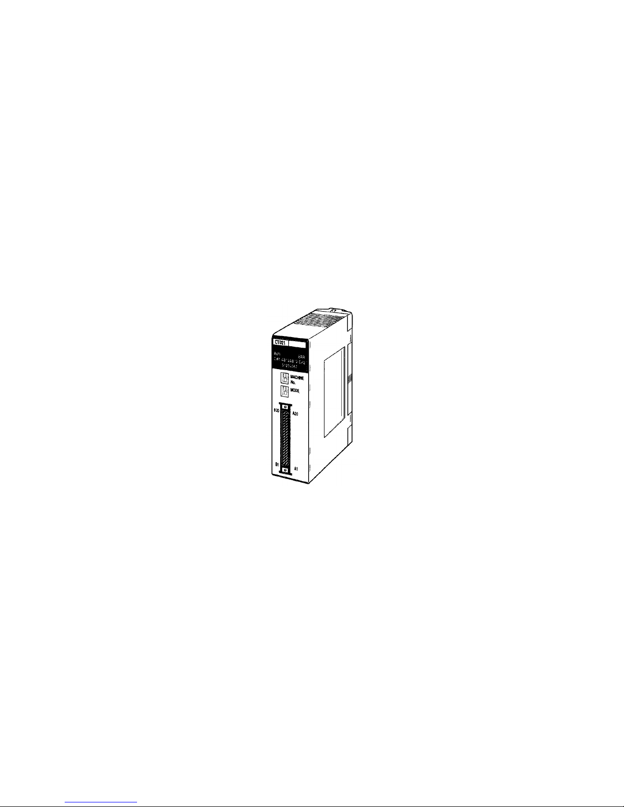
C200H-CT021
High-speed Counter Unit
Operation Manual
Revised December 2000
Page 2

iv
Page 3

v
Notice:
OMRON products are manufactured for use according to proper procedures by a qualified operator
and only for the purposes described in this manual.
The following conventions are used to indicate and classify precautions in this manual. Always heed
the information provided with them. Failure to heed precautions can result in injury to people or damage to the product.
!DANGER
Indicates information that, if not heeded, is likely to result in loss of life or serious injury.
!WARNING
Indicates information that, if not heeded, could possibly result in loss of life or serious
injury.
!Caution
Indicates information that, if not heeded, could result in relatively serious or minor injury,
damage to the product, or faulty operation.
OMRON Product References
All OMRON products are capitalized in this manual. The word “Unit” is also capitalized when it refers to
an OMRON product, regardless of whether or not it appears in the proper name of the product.
The abbreviation “Ch,” which appears in some displays and on some OMRON products, often means
“word” and is abbreviated “Wd” in documentation in this sense.
The abbreviation “PC” means Programmable Controller and is not used as an abbreviation for any-
thing else.
Visual Aids
The following headings appear in the left column of the manual to help you locate different types of
information.
Note Indicates information of particular interest for efficient and convenient opera-
tion of the product.
1,2,3... 1. Indicates lists of one sort or another, such as procedures, checklists, etc.
OMRON, 1996
All rights reserved. No part of this publication may be reproduced, stored in a retrieval system, or transmitted, in any form, o
r
by any means, mechanical, electronic, photocopying, recording, or otherwise, without the prior written permission o
f
OMRON.
No patent liability is assumed with respect to the use of the information contained herein. Moreover, because OMRON is constantly striving to improve its high-quality products, the information contained in this manual is subject to change without
notice. Every precaution has been taken in the preparation of this manual. Nevertheless, OMRON assumes no responsibility
for errors or omissions. Neither is any liability assumed for damages resulting from the use of the information contained in
this publication.
Page 4

vi
Page 5

vii
TABLE OF CONTENTS
PRECAUTIONS . . . . . . . . . . . . . . . . . . . . . . . . . . . . . . . . . . . xiii
1 Intended Audience . . . . . . . . . . . . . . . . . . . . . . . . . . . . . . . . . . . . . . . . . . . . . . . . . . . . . . . . xiv
2 General Precautions . . . . . . . . . . . . . . . . . . . . . . . . . . . . . . . . . . . . . . . . . . . . . . . . . . . . . . . xiv
3 Safety Precautions . . . . . . . . . . . . . . . . . . . . . . . . . . . . . . . . . . . . . . . . . . . . . . . . . . . . . . . . . xiv
4 Operating Environment Precautions . . . . . . . . . . . . . . . . . . . . . . . . . . . . . . . . . . . . . . . . . . . xv
5 Application Precautions . . . . . . . . . . . . . . . . . . . . . . . . . . . . . . . . . . . . . . . . . . . . . . . . . . . .xv
SECTION 1
Features and System Configuration . . . . . . . . . . . . . . . . . . . 1
1-1 Features . . . . . . . . . . . . . . . . . . . . . . . . . . . . . . . . . . . . . . . . . . . . . . . . . . . . . . . . . . . . . . . . . 2
1-2 System Configuration . . . . . . . . . . . . . . . . . . . . . . . . . . . . . . . . . . . . . . . . . . . . . . . . . . . . . . 3
SECTION 2
Specifications and Components. . . . . . . . . . . . . . . . . . . . . . . 5
2-1 Specifications . . . . . . . . . . . . . . . . . . . . . . . . . . . . . . . . . . . . . . . . . . . . . . . . . . . . . . . . . . . . 6
2-2 High-speed Counter Unit Components . . . . . . . . . . . . . . . . . . . . . . . . . . . . . . . . . . . . . . . . . 12
SECTION 3
Wiring . . . . . . . . . . . . . . . . . . . . . . . . . . . . . . . . . . . . . . . . . . . 15
3-1 External Connector Pins . . . . . . . . . . . . . . . . . . . . . . . . . . . . . . . . . . . . . . . . . . . . . . . . . . . . 16
3-2 Connector Wiring Method . . . . . . . . . . . . . . . . . . . . . . . . . . . . . . . . . . . . . . . . . . . . . . . . . . 16
3-3 I/O Circuit Configurations . . . . . . . . . . . . . . . . . . . . . . . . . . . . . . . . . . . . . . . . . . . . . . . . . .18
3-4 Wiring Examples of Encoder Inputs . . . . . . . . . . . . . . . . . . . . . . . . . . . . . . . . . . . . . . . . . . . 20
3-5 Wiring Example of External Control Inputs . . . . . . . . . . . . . . . . . . . . . . . . . . . . . . . . . . . . . 22
3-6 Example of External Output Wiring . . . . . . . . . . . . . . . . . . . . . . . . . . . . . . . . . . . . . . . . . . . 23
SECTION 4
Functions and Operating Modes. . . . . . . . . . . . . . . . . . . . . . 25
4-1 Operating Modes . . . . . . . . . . . . . . . . . . . . . . . . . . . . . . . . . . . . . . . . . . . . . . . . . . . . . . . . . . 26
4-2 DM and IR Bit Allocation. . . . . . . . . . . . . . . . . . . . . . . . . . . . . . . . . . . . . . . . . . . . . . . . . . .27
4-3 Linear Mode . . . . . . . . . . . . . . . . . . . . . . . . . . . . . . . . . . . . . . . . . . . . . . . . . . . . . . . . . . . . . 29
4-4 Circular Mode . . . . . . . . . . . . . . . . . . . . . . . . . . . . . . . . . . . . . . . . . . . . . . . . . . . . . . . . . . . . 31
4-5 Preset Mode. . . . . . . . . . . . . . . . . . . . . . . . . . . . . . . . . . . . . . . . . . . . . . . . . . . . . . . . . . . . . . 33
4-6 Gate Mode. . . . . . . . . . . . . . . . . . . . . . . . . . . . . . . . . . . . . . . . . . . . . . . . . . . . . . . . . . . . . . . 36
4-7 Cumulative Gate Mode . . . . . . . . . . . . . . . . . . . . . . . . . . . . . . . . . . . . . . . . . . . . . . . . . . . . .37
4-8 Sampling Mode . . . . . . . . . . . . . . . . . . . . . . . . . . . . . . . . . . . . . . . . . . . . . . . . . . . . . . . . . . . 37
4-9 Input Types . . . . . . . . . . . . . . . . . . . . . . . . . . . . . . . . . . . . . . . . . . . . . . . . . . . . . . . . . . . . . . 38
4-10 Counter Reset Conditions . . . . . . . . . . . . . . . . . . . . . . . . . . . . . . . . . . . . . . . . . . . . . . . . . . .41
4-11 Data Processing with PC . . . . . . . . . . . . . . . . . . . . . . . . . . . . . . . . . . . . . . . . . . . . . . . . . . . . 42
Page 6

viii
TABLE OF CONTENTS
SECTION 5
DM Area Allocation . . . . . . . . . . . . . . . . . . . . . . . . . . . . . . . . 45
5-1 DM Area Allocation in Simple Counter Mode . . . . . . . . . . . . . . . . . . . . . . . . . . . . . . . . . . . 46
5-2 DM Area Allocation in Linear and Circular Modes . . . . . . . . . . . . . . . . . . . . . . . . . . . . . . . 48
5-3 DM Area Allocation in Preset Mode . . . . . . . . . . . . . . . . . . . . . . . . . . . . . . . . . . . . . . . . . . . 54
5-4 DM Area Allocation in Gate, Cumulative Gate, and Sampling Modes . . . . . . . . . . . . . . . . 60
SECTION 6
Guidance for Program Development . . . . . . . . . . . . . . . . . . 63
6-1 Operating Steps . . . . . . . . . . . . . . . . . . . . . . . . . . . . . . . . . . . . . . . . . . . . . . . . . . . . . . . . . . . 64
6-2 Unit Number Setting . . . . . . . . . . . . . . . . . . . . . . . . . . . . . . . . . . . . . . . . . . . . . . . . . . . . . . . 65
SECTION 7
Program Development with Drum Function . . . . . . . . . . . . 67
7-1 Performance Specifications of Drum Function . . . . . . . . . . . . . . . . . . . . . . . . . . . . . . . . . . . 68
7-2 DM Area Settings and Functions. . . . . . . . . . . . . . . . . . . . . . . . . . . . . . . . . . . . . . . . . . . . . . 68
7-3 IR Area Settings and Functions . . . . . . . . . . . . . . . . . . . . . . . . . . . . . . . . . . . . . . . . . . . . . . . 71
7-4 I/O Signal Timing Chart . . . . . . . . . . . . . . . . . . . . . . . . . . . . . . . . . . . . . . . . . . . . . . . . . . . . 74
7-5 Data Transfer Programs . . . . . . . . . . . . . . . . . . . . . . . . . . . . . . . . . . . . . . . . . . . . . . . . . . . . . 75
7-6 Program Example for Linear Mode . . . . . . . . . . . . . . . . . . . . . . . . . . . . . . . . . . . . . . . . . . . . 80
7-7 Program Example for Circular Mode . . . . . . . . . . . . . . . . . . . . . . . . . . . . . . . . . . . . . . . . . . 82
SECTION 8
Program Development with Preset Function . . . . . . . . . . . . 85
8-1 Performance Specifications of Preset Function . . . . . . . . . . . . . . . . . . . . . . . . . . . . . . . . . . . 86
8-2 DM Area Settings and Functions. . . . . . . . . . . . . . . . . . . . . . . . . . . . . . . . . . . . . . . . . . . . . . 87
8-3 IR Area Settings and Functions . . . . . . . . . . . . . . . . . . . . . . . . . . . . . . . . . . . . . . . . . . . . . . . 89
8-4 I/O Signal Timing Chart . . . . . . . . . . . . . . . . . . . . . . . . . . . . . . . . . . . . . . . . . . . . . . . . . . . . 92
8-5 Data Transfer Programs . . . . . . . . . . . . . . . . . . . . . . . . . . . . . . . . . . . . . . . . . . . . . . . . . . . . . 93
8-6 Program Example for Preset Mode . . . . . . . . . . . . . . . . . . . . . . . . . . . . . . . . . . . . . . . . . . . . 97
SECTION 9
Program Development with Counting Function . . . . . . . . . 101
9-1 Performance Specifications of Counting Function . . . . . . . . . . . . . . . . . . . . . . . . . . . . . . . . 102
9-2 DM Area Settings and Functions. . . . . . . . . . . . . . . . . . . . . . . . . . . . . . . . . . . . . . . . . . . . . . 102
9-3 IR Area Settings and Functions . . . . . . . . . . . . . . . . . . . . . . . . . . . . . . . . . . . . . . . . . . . . . . . 103
9-4 I/O Signal Timing Chart . . . . . . . . . . . . . . . . . . . . . . . . . . . . . . . . . . . . . . . . . . . . . . . . . . . . 105
9-5 Program Example for Gate Mode . . . . . . . . . . . . . . . . . . . . . . . . . . . . . . . . . . . . . . . . . . . . . 107
9-6 Program Example for Cumulative Gate Mode . . . . . . . . . . . . . . . . . . . . . . . . . . . . . . . . . . . 109
9-7 Program Example 1 for Sampling Mode . . . . . . . . . . . . . . . . . . . . . . . . . . . . . . . . . . . . . . . . 111
9-8 Program Example 2 for Sampling Mode . . . . . . . . . . . . . . . . . . . . . . . . . . . . . . . . . . . . . . . . 112
Page 7

ix
TABLE OF CONTENTS
SECTION 10
Using IORD and IOWR Instructions . . . . . . . . . . . . . . . . . . 115
10-1 IORD and IOWR Instructions . . . . . . . . . . . . . . . . . . . . . . . . . . . . . . . . . . . . . . . . . . . . . . . . 116
10-2 Control Codes of IORD and IOWR Instructions . . . . . . . . . . . . . . . . . . . . . . . . . . . . . . . . . 119
10-3 Types of Data Written with IOWR Instruction . . . . . . . . . . . . . . . . . . . . . . . . . . . . . . . . . . . 121
10-4 Program Examples with IORD Instruction . . . . . . . . . . . . . . . . . . . . . . . . . . . . . . . . . . . . . . 123
10-5 Program Examples with IOWR Instruction . . . . . . . . . . . . . . . . . . . . . . . . . . . . . . . . . . . . . 124
10-6 Flags Used for IOWR Instruction and Data Transfer . . . . . . . . . . . . . . . . . . . . . . . . . . . . . . 126
SECTION 11
Error Processing and Troubleshooting . . . . . . . . . . . . . . . . 127
11-1 Error Processing . . . . . . . . . . . . . . . . . . . . . . . . . . . . . . . . . . . . . . . . . . . . . . . . . . . . . . . . . . 128
11-2 Errors Monitored with CPU . . . . . . . . . . . . . . . . . . . . . . . . . . . . . . . . . . . . . . . . . . . . . . . . . 130
Appendices
A Comparison with C200H-CT001-V1 . . . . . . . . . . . . . . . . . . . . . . . . . . . . . . . . . . . . . . . . . . 133
B Data Area Allocation . . . . . . . . . . . . . . . . . . . . . . . . . . . . . . . . . . . . . . . . . . . . . . . . . . . . . . 135
C DM Coding Sheet Unit Number
@
: DM
@@
00 to DM @@99 . . . . . . . . . . . . . . . . . . . . . . 145
D Using with CS1-series PCs . . . . . . . . . . . . . . . . . . . . . . . . . . . . . . . . . . . . . . . . . . . . . . . . . 147
Index . . . . . . . . . . . . . . . . . . . . . . . . . . . . . . . . . . . . . . . . . . . . 151
Revision History . . . . . . . . . . . . . . . . . . . . . . . . . . . . . . . . . . . 157
Page 8

xi
About this Manual:
This manual describes the installation and operation of the C200H-CT021 High-speed Counter Unit
and includes the sections described below.
Please read this manual carefully and be sure you understand the information provided before
attempting to install and operate the C200H-CT021 High-speed Counter Unit. Be sure to read the
precautions in the next section.
Section 1 provides a list of features and a system configuration example.
Section 2 provides the Unit’s basic specifications and describes its major components.
Section 3 explains how to connect various input and output devices to the High-speed Counter Unit.
Section 4 describes the High-speed Counter Unit functions and their operating modes.
Section 5 provides information on the DM and IR bit allocation in each mode.
Section 6 describes the steps required to operate the High-speed Counter Unit in each mode, the DM
required for unit number settings, and IR bit allocation.
Section 7 describes program development using the drum function in linear and circular modes.
Section 8 describes program development using the preset function.
Section 9 describes program development using the counting function in gate, latch, and sampling
modes.
Section 10 provide information on using the IORD and IOWR instructions.
Section 11 provides information on error processing and troubleshooting procedures.
The Appendices provide a comparison with the C200H-CT001-V1, information on data area allocation, and a DM coding sheet.
!WARNING
Failure to read and understand the information provided in this manual may result in personal injury or death, damage to the product, or product failure. Please read each section
in its entirety and be sure you understand the information provided in the section and
related sections before attempting any of the procedures or operations given.
Page 9

xiii
PRECAUTIONS
This section provides general precautions for using the Programmable Controller (PC) and the High-speed Counter
Unit.
The information contained in this section is important for the safe and reliable application of the PC and the
High-speed Counter Unit. You must read this section and understand the information contained before
attempting to set up or operate a PC system.
1 Intended Audience . . . . . . . . . . . . . . . . . . . . . . . . . . . . . . . . . . . . . . . . . . . . . xiv
2 General Precautions . . . . . . . . . . . . . . . . . . . . . . . . . . . . . . . . . . . . . . . . . . . . xiv
3 Safety Precautions . . . . . . . . . . . . . . . . . . . . . . . . . . . . . . . . . . . . . . . . . . . . . xiv
4 Operating Environment Precautions. . . . . . . . . . . . . . . . . . . . . . . . . . . . . . . . xv
5 Application Precautions . . . . . . . . . . . . . . . . . . . . . . . . . . . . . . . . . . . . . . . . . xv
Page 10
xiv
Intended Audience 1
1 Intended Audience
This manual is intended for the following personnel, who must also have
knowledge of electrical systems (an electrical engineer or the equivalent).
• Personnel in charge of installing FA systems.
• Personnel in charge of designing FA systems.
• Personnel in charge of managing FA systems and facilities.
2 General Precautions
The user must operate the product according to the performance specifications described in the operation manuals.
Before using the product under conditions which are not described in the
manual or applying the product to nuclear control systems, railroad systems,
aviation systems, vehicles, combustion systems, medical equipment, amusement machines, safety equipment, and other systems, machines, and equipment that may have a serious influence on lives and property if used
improperly, consult your OMRON representative.
Make sure that the ratings and performance characteristics of the product are
sufficient for the systems, machines, and equipment, and be sure to provide
the systems, machines, and equipment with double safety mechanisms.
This manual provides information for programming and operating OMRON
PCs and the High-speed Counter Unit. Be sure to read this manual before
attempting to use the High-speed Counter Unit and keep this manual close at
hand for reference during operation.
!WARNING
It is extremely important that a PC and all PC Units be used for the specified
purpose and under the specified conditions, especially in applications that can
directly or indirectly affect human life. You must consult with your OMRON
representative before applying a PC System to the abovementioned applications.
3 Safety Precautions
!WARNING
Do not attempt to take any Unit apart while the power is being supplied. Doing
so may result in electric shock.
!WARNING
Do not touch any of the terminals or terminal blocks while the power is being
supplied. Doing so may result in electric shock.
!WARNING
Do not attempt to disassemble, repair, or modify any Units. Any attempt to do
so may result in malfunction, fire, or electric shock.
!WARNING
Provide safety measures in external circuits (i.e., not in the Programmable
Controller), including the following items, in order to ensure safety in the system if an abnormality occurs due to malfunction of the PC or another external
factor affecting the PC operation. Not doing so may result in serious accidents.
• Emergency stop circuits, interlock circuits, limit circuits, and similar safety
measures must be provided in external control circuits.
Page 11
xv
Operating Environment Precautions 4
• The PC will turn OFF all outputs when its self-diagnosis function detects
any error or when a severe failure alarm (FALS) instruction is executed.
As a countermeasure for such errors, external safety measures must be
provided to ensure safety in the system.
• The PC outputs may remain ON or OFF due to deposition or burning of
the output relays or destruction of the output transistors. As a countermeasure for such problems, external safety measures must be provided
to ensure safety in the system.
4 Operating Environment Precautions
!Caution
Do not operate the control system in the following locations:
• Locations subject to direct sunlight.
• Locations subject to temperatures or humidity outside the range specified
in the specifications.
• Locations subject to condensation as the result of severe changes in temperature.
• Locations subject to corrosive or flammable gases.
• Locations subject to dust (especially iron dust) or salts.
• Locations subject to exposure to water, oil, or chemicals.
• Locations subject to shock or vibration.
!Caution
Take appropriate and sufficient countermeasures when installing systems in
the following locations:
• Locations subject to static electricity or other forms of noise.
• Locations subject to strong electromagnetic fields.
• Locations subject to possible exposure to radioactivity.
• Locations close to power supplies.
!Caution
The operating environment of the PC system can have a large effect on the
longevity and reliability of the system. Improper operating environments can
lead to malfunction, failure, and other unforeseeable problems with the PC
system. Be sure that the operating environment is within the specified conditions at installation and remains within the specified conditions during the life
of the system.
5 Application Precautions
Observe the following precautions when using the PC system.
!WARNING
Always heed these precautions. Failure to abide by the following precautions
could lead to serious or possibly fatal injury.
• Always ground the system to 100 Ω or less when installing the Units. Not
connecting to a ground of 100 Ω or less may result in electric shock.
• Always turn OFF the power supply to the PC before attempting any of the
following. Not turning OFF the power supply may result in malfunction or
electric shock.
• Mounting or dismounting I/O Units, CPU Units, Memory Units, or any
other Units.
• Assembling the Units.
Page 12

xvi
Application Precautions 5
• Setting DIP switches or rotary switches.
• Connecting cables or wiring the system.
• Connecting or disconnecting the connectors.
!Caution
Failure to abide by the following precautions could lead to faulty operation of
the PC or the system, or could damage the PC or PC Units. Always heed
these precautions.
• Fail-safe measures must be taken by the customer to ensure safety in the
event of incorrect, missing, or abnormal signals caused by broken signal
lines, momentary power interruptions, or other causes.
• Always use the power supply voltages specified in this manual. An incorrect voltage may result in malfunction or burning.
• Take appropriate measures to ensure that the specified power with the
rated voltage and frequency is supplied. Be particularly careful in places
where the power supply is unstable. An incorrect power supply may result
in malfunction.
• Install external breakers and take other safety measures against short-circuiting in external wiring. Insufficient safety measures against short-circuiting may result in burning.
• Do not apply voltages to the Input Units in excess of the rated input voltage. Excess voltages may result in burning.
• Do not apply voltages or connect loads to the Output Units in excess of
the maximum switching capacity. Excess voltage or loads may result in
burning.
• Disconnect the functional ground terminal when performing withstand
voltage tests. Not disconnecting the functional ground terminal may result
in burning.
• Be sure that all the mounting screws, terminal screws, and cable connector screws are tightened to the torque specified in this manual. Incorrect
tightening torque may result in malfunction.
• Leave the label attached to the Unit when wiring. Removing the label may
result in malfunction if foreign matter enters the Unit.
• Remove the label after the completion of wiring to ensure proper heat dissipation. Leaving the label attached may result in malfunction.
• Double-check all wiring and switch settings before turning ON the power
supply. Incorrect wiring may result in burning.
• Wire correctly. Incorrect wiring may result in burning.
• Mount Units only after checking terminal blocks and connectors com-
pletely.
• Be sure that the terminal blocks, Memory Units, expansion cables, and
other items with locking devices are properly locked into place. Improper
locking may result in malfunction.
• Check the user program for proper execution before actually running it on
the Unit. Not checking the program may result in an unexpected operation.
• Confirm that no adverse effect will occur in the system before attempting
any of the following. Not doing so may result in an unexpected operation.
• Changing the operating mode of the PC.
• Force-setting/force-resetting any bit in memory.
• Changing the present value of any word or any set value in memory.
Page 13

xvii
Application Precautions 5
• Resume operation only after transferring to the new CPU Unit the contents of the DM Area, HR Area, and other data required for resuming
operation. Not doing so may result in an unexpected operation.
• Do not pull on the cables or bend the cables beyond their natural limit.
Doing either of these may break the cables.
• Do not place objects on top of the cables or other wiring lines. Doing so
may break the cables.
• Use crimp terminals for wiring. Do not connect bare stranded wires
directly to terminals. Connection of bare stranded wires may result in
burning.
• When replacing parts, be sure to confirm that the rating of a new part is
correct. Not doing so may result in malfunction or burning.
• Before touching a Unit, be sure to first touch a grounded metallic object in
order to discharge any static built-up. Not doing so may result in malfunction or damage.
Page 14

1
SECTION 1
Features and System Configuration
This section provides a list of features and a system configuration example.
1-1 Features. . . . . . . . . . . . . . . . . . . . . . . . . . . . . . . . . . . . . . . . . . . . . . . . . . . . . . 2
1-2 System Configuration . . . . . . . . . . . . . . . . . . . . . . . . . . . . . . . . . . . . . . . . . . . 3
Page 15

2
Fe at ur es Section 1-1
1-1 Features
The C200H-CT021 High-speed Counter is a Special I/O Unit for the C200H,
C200HS, C200HX, C200HG, and C200HE PCs.
The High-speed Counter Unit has the following features.
Two Built-in Counters The High-speed Counter Unit has two high-speed increment/decrement
counters, each of which can be connected to an incremental encoder with
open collector output to count line driver input pulses at a rate of 75,000 cps
max.
Built-in Line Driver Input
Circuit
An encoder with RS-422 line driver output can be directly connected to the
High-speed Counter Unit. Line driver input resists noise, thus making it possible to connect the encoder to the High-speed Counter Unit through a long
cable or to wire the cable in places where noise may be generated.
An open collector output from an encoder can be connected as a line driver
input to the High-speed Counter Unit through the C500-AE001 Encoder Conversion Adapter.
Counts in BCD or
Hexadecimal
The High-speed Counter Unit can count BCD or hexadecimal values.
The following are the available counting ranges.
BCD: –8,388,608 to 8,388,607
Hexadecimal: 800000 to FFFFFF (–8,388,608 to –1) and 000000 to
7FFFFF (0 to 8,388,607)
Refer to page 10 for the data configuration of the count value in hexadecimal.
Seven Operating Modes The High-speed Counter Unit has the following three functions and seven
operating modes. None of the three functions are available to the High-speed
Counter Unit in simple counter mode, which is the basic operating mode of
the High-speed Counter Unit.
Simple Counter Mode: Counts the number of input pulses.
Drum Function
Linear Mode: Controls outputs when the count value is in a preset range.
The High-speed Counter Unit counts the number of pulses
within the available counting ranges.
Circular Mode: Controls outputs when the count value is within a preset
range. The High-speed Counter Unit counts the number of
pulses from zero to the maximum countable value preset with
the High-speed Counter Unit. The count value is reset to zero
after it reaches the maximum countable value.
Preset Counter Function
Preset Mode: Controls outputs after counting a preset value.
Counting Function
Gate Mode: Counts the number of pulses only while the control
input signal is turned ON.
Cumulative Gate Mode: Accumulates the number of pulses whenever the
control input signal is turned ON.
Sampling Mode: Counts the number of pulses for a preset interval
from the rising edge of the control signal.
Eight Types of External
Outputs
The High-speed Counter Unit has eight external outputs, either NPN or PNP.
Three Types of Pulse
Inputs
The following three types of pulse inputs are available.
• Offset phase inputs
Page 16
3
System Configuration Section 1-2
• Up and down pulse inputs
• Pulse and direction inputs
The High-speed Counter Unit has a function to multiply offset phase inputs by
two or four. The resolution of the High-speed Counter Unit can be increased in
proportion to the number of pulses input from encoders.
Change Present and Set
Values During High-speed
Counter Unit Operation
The High-speed Counter Unit in normal operation uses settings that are read
when the High-speed Counter Unit is turned ON. The settings, which include
the present counter values of the High-speed Counter Unit, can be changed
anytime.
1-2 System Configuration
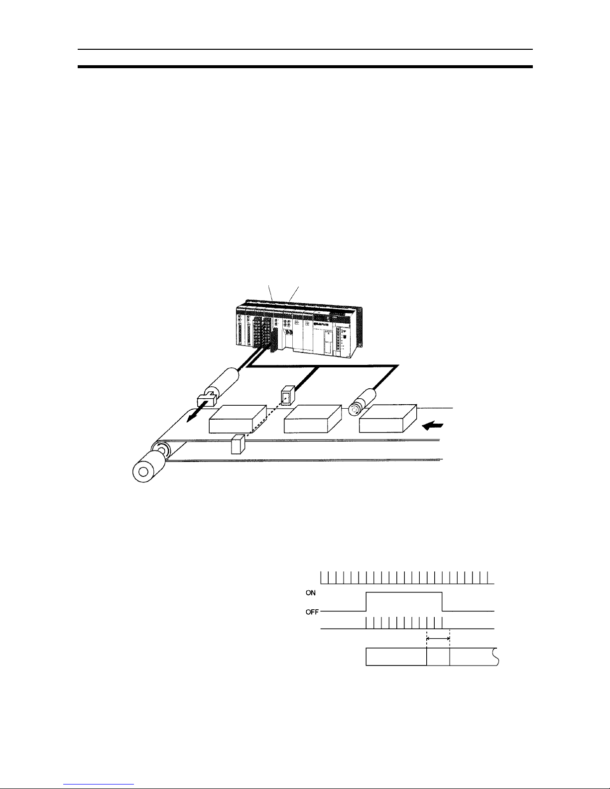
Discriminating Product
Sizes
In the following example, the size of each product on the belt conveyor is measured and improper-sized products are removed from the line using the solenoid.
The High-speed Counter Unit counts the number of pulses that is input from
the encoder while each product is passing between the emitter and receiver of
the through-beam photoelectric sensor.
When the count value of a product is not within the range preset with the
High-speed Counter Unit, the solenoid will be activated and the product will be
removed from the line.
C200H-OA221
AC Output Unit
C200H-CT021
High-speed Counter Unit
Solenoid:
Used to remove
improper-sized
products.
Through-beam
Photoelectric Sensor:
Used to sense the
products.
Incremental Encoder:
Used to sense the speed
of the belt conveyor.
Motor
Belt conveyor
C200HX
Incremental
encoder output
Photoelectric
sensor output
Count value
Discrimination
criteria
Reject OK Reject
Page 17

4
System Configuration Section 1-2
Number of Mounted Units The maximum number of High-speed Counter Units and other Special I/O
Units that can be mounted to the C200HX, C200HG, or C200HE CPU Rack,
Expansion I/O Rack, or Slave Rack is 16 and the maximum number of those
mounted to any other PC is 10.
Note 1. A maximum of four High-speed Counter Units can be mounted to the Slave
Rack.
2. Do not mount the High-speed Counter Unit to the two slots on the right of
the CPU.
3. Do not mount the High-speed Counter Unit to the Slave Rack if the IORD
or IOWR instruction is to be used with the C200HX, C200HG, or C200HE.
Page 18

5
SECTION 2
Specifications and Components
This section provides the Unit’s basic specifications and describes its major components.
2-1 Specifications . . . . . . . . . . . . . . . . . . . . . . . . . . . . . . . . . . . . . . . . . . . . . . . . . 6
2-1-1 General Specifications . . . . . . . . . . . . . . . . . . . . . . . . . . . . . . . . . . . 6
2-1-2 Characteristics . . . . . . . . . . . . . . . . . . . . . . . . . . . . . . . . . . . . . . . . . 6
2-1-3 I/O Electrical Specifications . . . . . . . . . . . . . . . . . . . . . . . . . . . . . . 7
2-1-4 Counting Speed . . . . . . . . . . . . . . . . . . . . . . . . . . . . . . . . . . . . . . . . 9
2-1-5 BCD or Hexadecimal Count Values. . . . . . . . . . . . . . . . . . . . . . . . . 10
2-1-6 Dimensions. . . . . . . . . . . . . . . . . . . . . . . . . . . . . . . . . . . . . . . . . . . . 11
2-1-7 Dimensions with High-speed Counter Unit Mounted . . . . . . . . . . . 11
2-2 High-speed Counter Unit Components . . . . . . . . . . . . . . . . . . . . . . . . . . . . . 12
2-2-1 Nomenclature . . . . . . . . . . . . . . . . . . . . . . . . . . . . . . . . . . . . . . . . . . 12
2-2-2 Indicator Functions . . . . . . . . . . . . . . . . . . . . . . . . . . . . . . . . . . . . . 12
2-2-3 Switch Settings. . . . . . . . . . . . . . . . . . . . . . . . . . . . . . . . . . . . . . . . . 13
2-2-4 Rear Setting Switch . . . . . . . . . . . . . . . . . . . . . . . . . . . . . . . . . . . . . 13
Page 19
6
Specifications Section 2-1
2-1 Specifications
2-1-1 General Specifications
The general specifications conform to the C-series specifications.
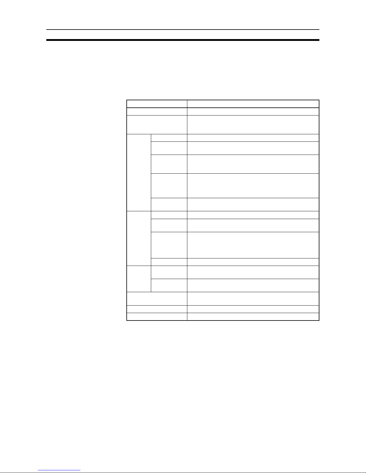
2-1-2 Characteristics
Item Specification
Number of counters 2
Operating modes Simple counter, linear counter, circular counter, preset
counter, gate counter, cumulative gate counter, and sampling modes.
Count
inputs
Input signals Counter 1 inputs A and B and counter 2 inputs A and B
Signal levels RS-422 line driver signal (equivalent to Am26LSS31), 12
or 24 VDC (selectable)
Ty p e s o f
inputs
Offset phase inputs
Up and down pulse inputs
Pulse+direction inputs
Counting rate Voltage input: 50,000 cps max. at a line driver input rate
of 75,000 cps max.
The counting speed of the number of offset phase input
pulses varies with the encoder. Refer to page 9 for details.
Others The multiple function (x 1, x 2, or x 4) can be selected for
offset phase input
External
inputs
Input signal Counter 1 input Z, Counter 2 input Z
Signal levels RS-422 line driver signal (equivalent to Am26LSS31), 12
or 24 VDC (selectable)
Input signal Counter 1 external control input IN1
Counter 1 external control input IN2
Counter 2 external control input IN1
Counter 2 external control input IN2
Signal levels 12 VDC and 24 VDC
External
outputs
Outputs External outputs 0 to 7, 8 points
NPN or PNP output (selectable)
Switching
capacity
Output power supply: 16 to 80 mA at 5 to 24 VDC
Internal current consumption
400 mA max. at 5 VDC (Supplied from Backplane.)
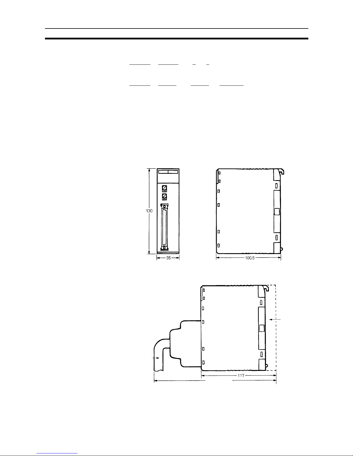
Dimensions (mm) 130 × 35 × 100.5 (H × W × D)
Weight 305 g (excluding connectors)
Page 20
7
Specifications Section 2-1
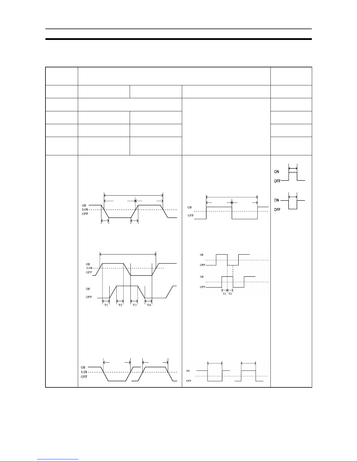
2-1-3 I/O Electrical Specifications
Input Characteristics
Item Counter inputs A, B, and Z External
control inputs
IN1 and IN2
Input voltage 12 VDC ±10% 24 VDC ±10% RS-422 line driver 12 to 24 VDC
±10%
Input current 14 mA (typical) at each voltage (12.9 to
17.1 mA)
Conform to RS-422 line driver
(Am26LS31) specifications.
4 to 11 mA
ON voltage
(min.)
5.6 VDC 15.2 VDC 10.2 VDC
OFF voltage
(max.)
2.4 VDC 4.8 VDC 3.0 VDC
ON/OFF
response
time (max.)
--- --- 0.1 ms
Minimum
response
pulse
Counter Inputs A and B
Waveform
Input rising time/calling time: 3 µs max. at
50 kHz with pulses with a duty factor of
50%
10 µs
min.
3 µs max.3 µs max.
Relationship between A and B phases with
offset phase input
20 µs min.
Phase B
T1, T2, T3, and T4: 4.5 µs min.
The switching time between A and B
phases must be 4.5 µs min.
Counter Input Z
A pulse width of 100 µs min. is required.
100 µs
min.
100 µs
min.
20 µs min.
min.
10 µs
Phase A
Counter Inputs A and B
Waveform
At 75 kHz with pulses with a duty
factor of 50%
13.3 µs min.
6.7 µs
min.
6.7 µs
min.
0 V
Relationship between A and B
phases with offset phase input
Phase A
Phase B 0 V
0 V
T1 and T2: 3.2 µs min.
The switching time between A and B
phases must be 3.2 µs min.
Counter Input Z
A pulse width of 100 µs min. is
required.
100 µs min. 100 µs min.
0 V
When
accessing
these signals
from the PC,
the signals
must be ON
longer than the
PC's c
ycle time.
0.1 ms min.
0.1 ms min.
Page 21
8
Specifications Section 2-1
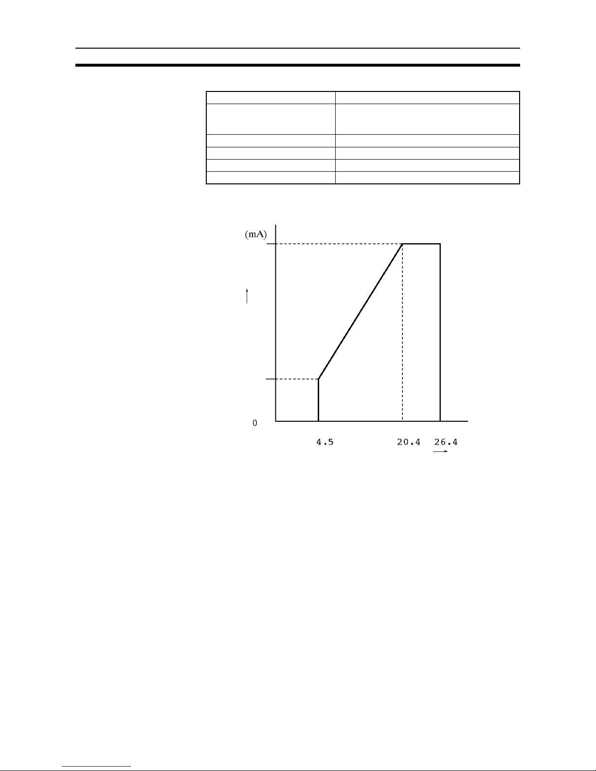
Output Characteristics
The maximum switching current depends upon the power supply voltage, as
shown below.
Note The output current must not exceed 0.5 A per common (i.e., eight points), oth-
erwise the built-in fuse will blow out. The built-in fuse cannot be replaced by
the user.
Item External Outputs 0 to 7
Max. switching capacity 16 mA at 4.5 VDC to 80 mA at 26.4 VDC
(See the following graph.)
320 mA max./common
Leakage current 0.1 A max.
Residual voltage 0.8 V max.
ON/OFF response time 0.2 ms max.
External power supply 5 to 24 VDC ±10% (50 mA max. at 26.4 VDC)
(VDC)
80
50
16
External power supply voltage
Maximum switching capacity
Page 22
9
Specifications Section 2-1
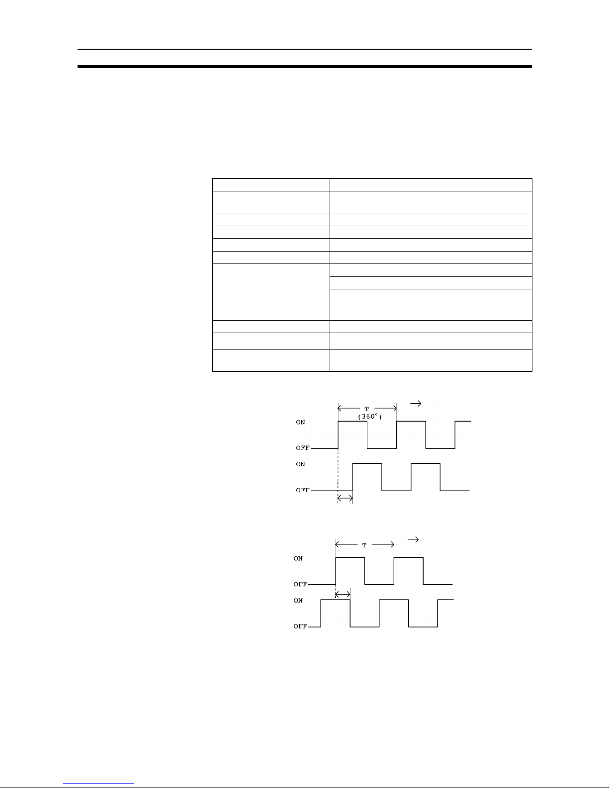
2-1-4 Counting Speed
The maximum response pulse frequency of the High-speed Counter for offset
phase inputs is determined with the type of increment encoder connected to
the High-speed Counter. In this following example, OMRON’s E6B-CWZ3C
Encoder is connected to the High-speed Counter.
Example:E6B-CWZ3C (500 pulses/time)
Ratings
Clockwise (CW) Rotation Phase A is advanced
1
⁄4±1⁄8T phase ahead of phase B.
Counterclockwise (CCW)
Rotation
Phase A is delayed
1
⁄4±1⁄8T phase behind phase B.
Item Specification
Power supply voltage 5 VDC (–5%) to 12 V (+10%) with a peak-to-peak rip-
ple rate of 5% max.
Current consumption 50 mA max.
Resolution (P/R) 500
Output phases Phase A, phase B, phase Z
Output type Open collector output
Output capacity Applied voltage: 30 VDC max.
Sink current: 80 mA max.
Residual voltage:
1 V max (when the sink current is 80 mA)
0.4 V max (when the sink current is 20 mA)
Max. response frequency 30 KHz
Output phase difference
A/B phase difference 90°±45° (
1
⁄4±1⁄8T)
Output rise/fall time 1.0 µs max. (Control output voltage 5 V, load resis-
tance 1 KΩ, cord length 50 cm)
Phase A
Phase B
CW direction
1
⁄4T±1⁄8T (90°±45°)
1
⁄4T±1⁄8T (90°±45°)
(360°)
CCW direction
Phase A
Phase B
Page 23
10
Specifications Section 2-1
The output offset phase is 90°±45°. Therefore, the greatest offset phase of the
encoder is 45° (i.e., 90° – 45°).
The Unit requires a minimum offset phase of 3.2 µs.
Thus:
Inverting the period yields the maximum frequency of 27.7K cps.
From the above, use the High-speed Counter at a maximum counting speed
of 27,000 cps if the High-speed Counter is connected to an encoder with a
maximum response frequency of 27,000 cps.
Note The pulse width of counter input Z must be 100 µs min. if the counter is reset
with a Z-phase input from the encoder at a repetition frequency of 2000 cps
max.
The repetition frequency of line driver input must be 1,000 cps when considering the software processing time.
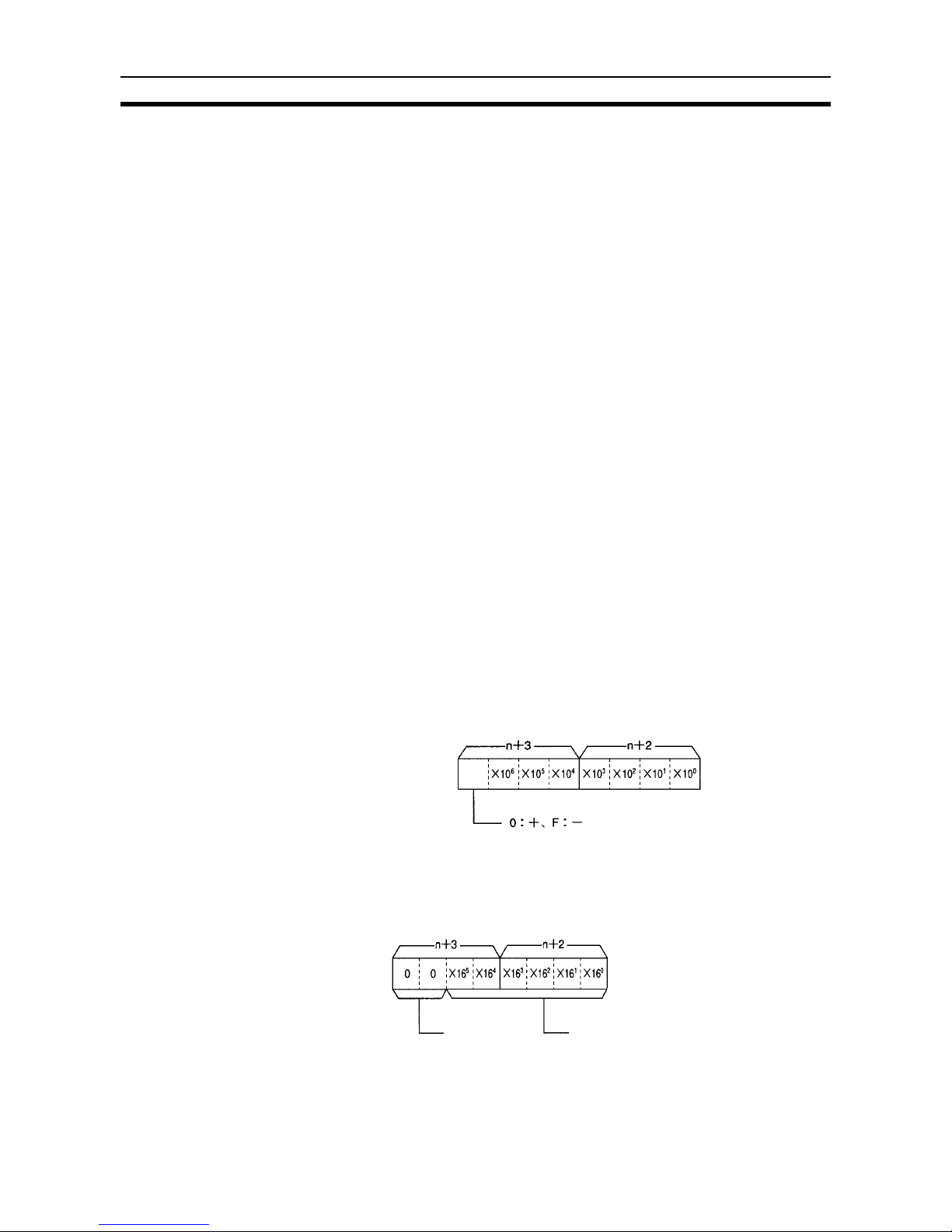
2-1-5 BCD or Hexadecimal Count Values
The High-speed Counter Unit can set the present counter value and the upper
and lower limit count values in BCD or hexadecimal.
The High-speed Counter Unit can process hexadecimal values faster than
BCD values because it need not convert the hexadecimal values into BCD
values.
Refer to the following for the data configuration’s BCD and hexadecimal count
values.
BCD Example:Present counter value
The above is the data configuration of the present counter value stored in
words n+2 and n+3 of the data area.
Counting range: –8,388,608 to 8,388,607
Hexadecimal
The sign of the hexadecimal value is determined with 2’s complement of the
leftmost bit.
4.5 µ s
T
--------------
45°
360°
-----------<
(When the rise and fall of the Encoder's
output are equivalent.)
T36µs<
(T is the minimum pulse period that for
responses.)
1
T
---
1
36 µ s
------------- 27.7K cps=<
(78 revolutions/s when there are
500 pulses/revolution)
Sign
Set to 0.
Data within a range of 000000 to
FFFFFF is stored. Refer to the
following for the actual count values.
Page 24
11
Specifications Section 2-1
Example:
In the following example, the count value is FFFFFF.
– {1000000
– (FFFFFF)} = – 1 = – 1
Hex. Hex. Hex. BCD
In the following example, the count value is 800000.
– {1000000
– (800000)} = – 800000 = – 8,388,608
Hex. Hex. Hex. BCD
Therefore the following counting range can be obtained.
Hexadecimal BCD
800000 (–8,388,608)
to to
FFFFFF (–1)
00
to to
7FFFFF (8,388607)
2-1-6 Dimensions
2-1-7 Dimensions with High-speed Counter Unit Mounted
Connecting
cable
Backplane
Approx. 200
Page 25
12
High-speed Counter Unit Components Section 2-2
2-2 High-speed Counter Unit Components
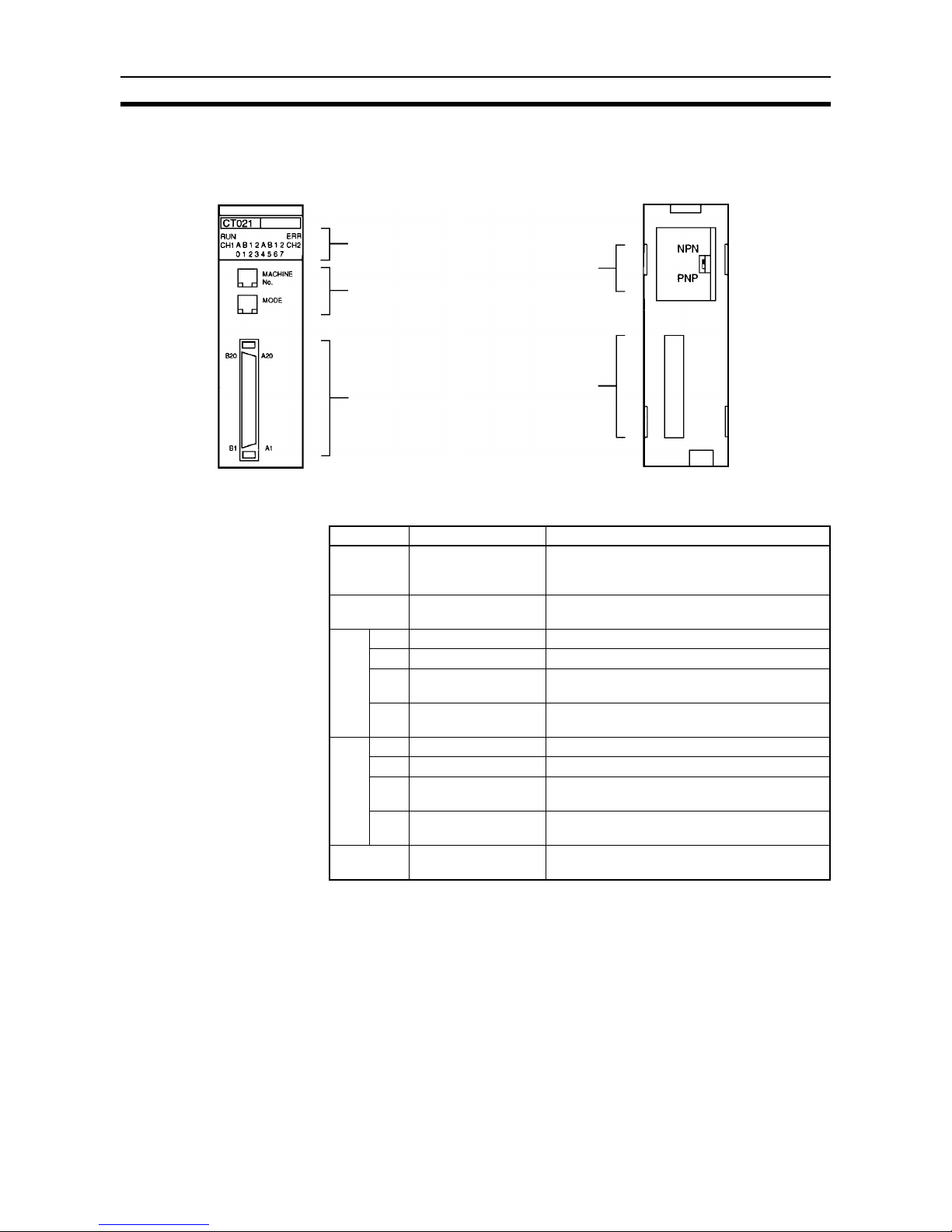
2-2-1 Nomenclature
2-2-2 Indicator Functions
Indicator Name Function
RUN Operation Lit when the High-speed Counter is in normal
counting operation. Not lit when the High-speed
Counter stops counting pulses.
ERR Error Lit when an error, counter overflow, or counter
underflow results.
CH1 A Counter 1 input A Lit when counter 1 input A is ON.
B Counter 1 input B Lit when counter 1 input B is ON.
1 Counter 1 external
control input IN1
Lit when external control input IN1 is ON.
2 Counter 1 external
control input IN2
Lit when external control input IN2 is ON.
CH2 A Counter 2 input A Lit when counter 2 input A is ON.
B Counter 2 input B Lit when counter 2 input B is ON.
1 Counter 2 external
control input IN1
Lit when external control input IN1 is ON.
2 Counter 2 external
control input IN2
Lit when external control input IN2 is ON.
01234567 External output These indicators light when the corresponding
external output (0 through 7) is ON.
Indicators
Rotary switches
External connector
Rear setting
switch
Backplane
connector
Page 26
13
High-speed Counter Unit Components Section 2-2
2-2-3 Switch Settings
There are two rotary switches on the front panel of the High-speed Counter
Unit, which can be used for unit number and operating mode settings.
Note 1. Be sure to turn OFF the High-speed Counter Unit before setting the unit
number and operating mode.
2. Use a flat-blade screwdriver for rotary switch settings.
3. Be sure not to damage the grooves of the rotary switches with the flat-
blade screwdriver. Do not leave either of the rotary switches set midway
between numbers. Otherwise a setting error may occur.
Note The unit number must not be same as the unit number of any other Special I/
O Unit or Position Control Unit in the same system, otherwise a setting error
will result. Each unit number in the system must be unique.
The unit number can be set within a range of 0 to 9 if the C200H, C200HS,
C200HE-CPU11/32/42(-Z), C200HG-CPU33/43(-Z), or C200HX-CPU34/44(Z) is used with the High-speed Counter Unit.
The operating mode must be set within a range of 0 to 6. Do not set the operating mode to 7, 8, or 9, otherwise the High-speed Counter Unit will not operate.
2-2-4 Rear Setting Switch
The rear setting switch of the High-speed Counter Unit is used to select the
output mode.
Switch Setting Function
MACHINE No. Unit number setting Set the switch within a range of 0 to F.
MODE Operating mode set-
ting
Set the switch within a range of 0 to 6.
0: Simple counter mode
1: Linear mode
2: Circular mode
3: Preset mode
4: Gate mode
5: Cumulative gate mode
6: Sampling mode
7 to 9: Not used
Switch Function
NPN Outputs 0 to 7 will be NPN outputs.
PNP Outputs 0 to 7 will be PNP outputs.
Page 27

15
SECTION 3
Wiring
This section explains how to connect various input and output devices to the High-speed Counter Unit.
!WARNING
Do not touch the terminals while the power is being supplied. Otherwise
an electric shock may occur.
3-1 External Connector Pins. . . . . . . . . . . . . . . . . . . . . . . . . . . . . . . . . . . . . . . . . 16
3-2 Connector Wiring Method . . . . . . . . . . . . . . . . . . . . . . . . . . . . . . . . . . . . . . . 16
3-3 I/O Circuit Configurations . . . . . . . . . . . . . . . . . . . . . . . . . . . . . . . . . . . . . . . 18
3-4 Wiring Examples of Encoder Inputs . . . . . . . . . . . . . . . . . . . . . . . . . . . . . . . 20
3-5 Wiring Example of External Control Inputs. . . . . . . . . . . . . . . . . . . . . . . . . . 22
3-6 Example of External Output Wiring. . . . . . . . . . . . . . . . . . . . . . . . . . . . . . . . 23
Page 28
16
External Connector Pins Section 3-1
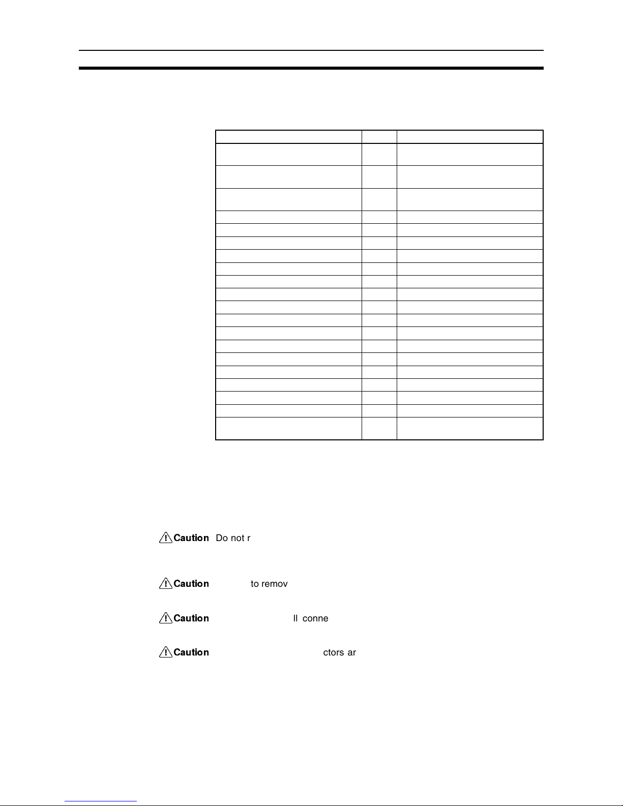
3-1 External Connector Pins
The following table lists the allocation of the external connector pins on front
side of the High-speed Counter Unit.
Each external connector is attached with a soldering terminal (Fujitsu FCN361J040).
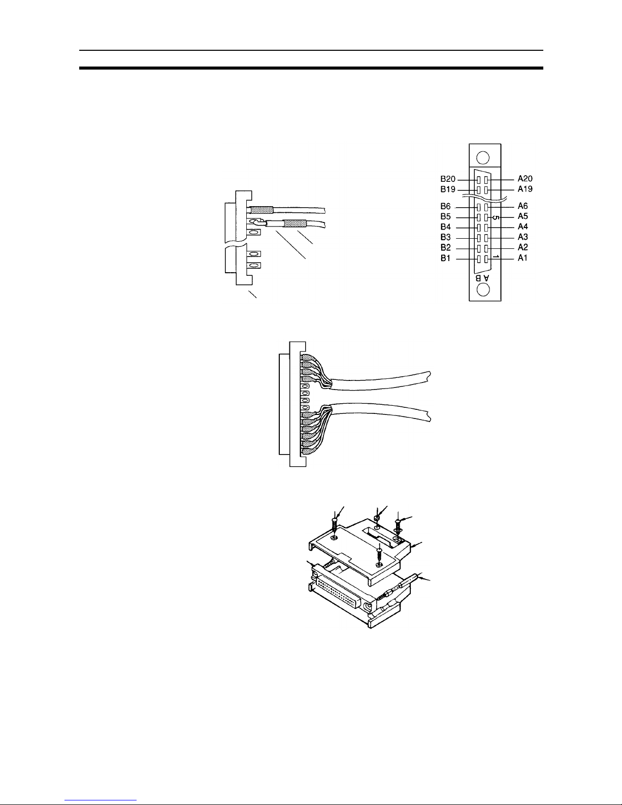
3-2 Connector Wiring Method
The connectors of the High-speed Counter Unit must be soldered.
!Caution
Do not remove the label on top of the High-speed Counter Unit before wiring
the connectors, otherwise wire cuttings may fall into the High-speed Counter
Unit and short-circuit the internal circuitry causing the Unit to malfunction.
!Caution
Be sure to remove the label on top of the High-speed Counter Unit after wiring
the connectors, otherwise the Unit in operation may overheat and malfunction.
!Caution
Make sure that all connectors are correctly connected to the High-speed
Counter Unit, otherwise the Unit may burn.
!Caution
Make sure that all connectors are wired correctly, otherwise the High-speed
Counter Unit may burn.
Note 1. The thickness of each wire connected to the High-speed Counter Unit
must be 0.3 mm
2
max.
Row B Pin no. Row A
Counter 1 external control input IN2:
12 or 24 VDC
20 Counter 2 external control input IN2:
12 or 24 VDC
Counter 1 external control input IN1:
12 or 24 VDC
19 Counter 2 external control input IN1:
12 or 24 VDC
Counter 1 external control input IN1/
IN2: COM
18 Counter 2 external control input IN1/
IN2: COM
Counter 1 input Z: 24 VDC 17 Counter 2 input Z: 24 VDC
Counter 1 input Z: 12 VDC 16 Counter 2 input Z: 12 VDC
Counter 1 input Z: + (Line driver) 15 Counter 2 input Z: + (Line driver)
Counter 1 input Z: – (Line driver) 0 V 14 Counter 2 input Z: – (Line driver) 0 V
Counter 1 input B: 24 VDC 13 Counter 2 input B: 24 VDC
Counter 1 input B: 12 VDC 12 Counter 2 input B: 12 VDC
Counter 1 input B: + (Line driver) 11 Counter 2 input B: + (Line driver)
Counter 1 input B: – (Line driver) 0 V 10 Counter 2 input B: – (Line driver) 0 V
Counter 1 input A: 24 VDC 9 Counter 2 input A: 24 VDC
Counter 1 input A: 12 VDC 8 Counter 2 input A: 12 VDC
Counter 1 input A: + (Line driver) 7 Counter 2 input A: + (Line driver)
Counter 1 input A: – (Line driver) 0 V 6 Counter 2 input A: – (Line driver) 0 V
External output 0 5 External output 4
External output 1 4 External output 5
External output 2 3 External output 6
External output 3 2 External output 7
External output 0 to 7 COM: 0 V 1 Power supply for external outputs 0
to 7: 5 to 24 VDC
Page 29
17
Connector Wiring Method Section 3-2
2. Do not short-circuit any terminals when wiring. Covering each soldered
portion with an insulating tube is recommended.
3. When using multi-conductor cables, separate the input and output cables.
Wires
Cable Separation
Assembling Connectors
The following Fujitsu 360-series parts are available.
1. FCN-361J040-AU (solder terminal)
FCN-360C040-B (cover)
2. FCN-363J040 (solderless terminal housing)
FCN-363J-AU (contact)
3. FCN-367J040-AU/F (solderless terminal)
Insulating tube
Wire (Thickness: 0.3 mm
2
max.)
Connector
Connector terminal side
Input cable
Output cable
Two, M2 pan-head screws
(8 mm long)
Connector jack
Four, M2 nuts
Two, M2 pan-head screws
(10 mm long)
Case
Screw
Page 30
18
I/O Circuit Configurations Section 3-3
Wiring Precautions Refer to the following for noise prevention when wiring counter inputs A, B,
and Z.
1,2,3... 1. Use shielded, twisted-pair cable and ground the shield to a resistance of
100 Ω max.
2. Make the wiring as short as possible and do not run the wires parallel to
lines that produce a lot of noise, such as high-power lines.
3. Try to use a separate stabilized power supply for the High-speed Counter
Unit and another power supply for other I/O.
4. Be sure not to reverse the polarity when wiring a line driver input.
5. Be sure to connect wires to a 5- to 24-VDC output power supply terminal
and COM (0 V) terminal correctly. If the wires are connected to these terminals reversely, the built-in fuse will blow out. The built-in fuse cannot be
replaced by the user.
3-3 I/O Circuit Configurations
Input Configuration Terminals numbers in parentheses are used with counter 2.
filterfilterfilter
Rectifier
Rectifier
Terminal number Name
Counter 1 external control IN2: 12 or 24 VDC
Counter 1 external control IN1/IN2: Input common
Counter 1 input Z: 24 VDC
Counter 1 external control IN1: 12 or 24 VDC
Counter 1 input Z: 12 VDC
Counter 1 input Z: 0 V
Counter 1 input B: 24 VDC
Counter 1 input B: 12 VDC
Counter 1 input B: 0 V
Counter 1 input A: 24 VDC
Counter 1 input A: 12 VDC
Counter 1 input A: 0 V
Page 31

19
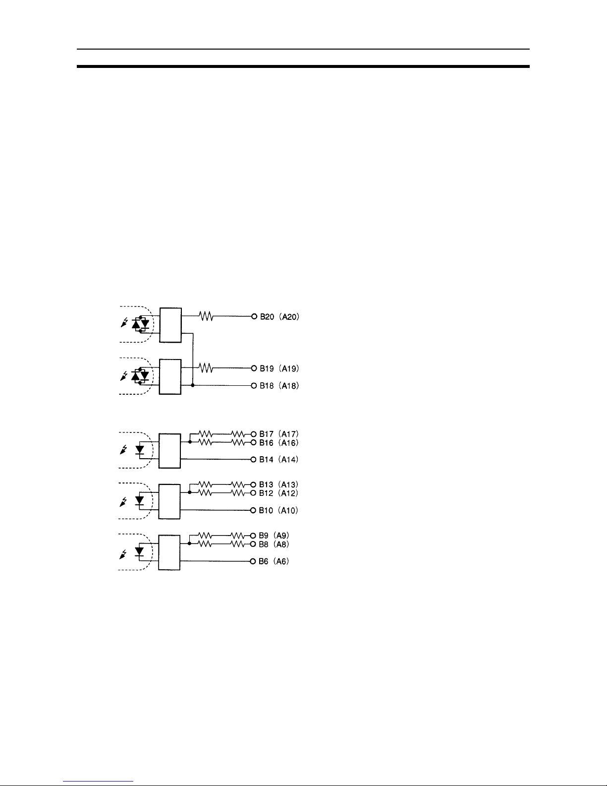
I/O Circuit Configurations Section 3-3
Line Driver Input
Configuration
Terminals numbers in parentheses are used with counter 2.
External Output Configuration
Counter 1 input Z: (+)
Counter 1 input Z: (−)
Counter 1 input B: (+)
Counter 1 input B: (−)
Counter 1 input A: (+)
Counter 1 input A: (−)
Terminal number Name
Internal circuitry
Fuse (1 A)
(NPN/PNP output)
Fuse (1 A)
A1: 5- to 24 VDC-power
supply for external
outputs 0 to 7
B5: External output 0
B4: External output 1
B3: External output 2
B2: External output 3
A5: External output 4
A4: External output 5
A3: External output 6
A2: External output 7
B1: External output 0 to 7
COM : 0 V
Page 32

20
Wiring Examples of Encoder Inputs Section 3-4
3-4 Wiring Examples of Encoder Inputs
The following are wiring examples of an encoder with A, B, and Z-phase outputs.
Wiring Example 1: 12-VDC Open-collector Encoder
Wiring Example 2: 12-VDC
Voltage-output (Sink
Load) Encoder
In the following example, an input to the High-speed Counter Unit will be
turned OFF when an output from the encoder is H and an input to the Unit will
be turned ON when an output from the encoder is L.
C200H-CT021 High-speed Counter Unit
Counter input A
Rectifierfilter
Counter input B
Counter input Z
24 V
12 V
0 V
24 V
12 V
0 V
24 V
12 V
0 V
12-VDC 12 VDC
power
supply
0 V
Shielded, twisted-pair cable
Encoder
Powe r
A phase
Encoder
output
B phase
Z phase
Rectifier
Rectifierfilter Rectifier
Counter input A
Counter input B
Counter input Z
C200H-CT021 High-speed Counter Unit
Shielded, twisted-pair cable
24 V
12 V
0 V
24 V
12 V
0 V
24 V
12 V
0 V
12-VDC 12 VDC
power
supply
0 V
Encoder
Powe r
A phase
B phase
Z phase
Encoder
output
Page 33

21
Wiring Examples of Encoder Inputs Section 3-4
Wiring Example 3: 12-VDC Voltage-output (Source load) Encoder
Wiring Example 4: Line-driver Output (Am26LS31 or Equivalent) Encoder
Rectifierfilter Rectifier
Counter input A
Counter input B
Counter input Z
C200H-CT021 High-speed Counter Unit
Shielded, twisted-pair cable
24 V
12 V
0 V
24 V
12 V
0 V
24 V
12 V
0 V
12-VDC 12 VDC
power
supply
0 V
Encoder
A phase
B phase
Z phase
C200H-CT021 High-speed Counter Unit
Counter input A
Counter input B
Counter input Z
Shielded, twisted-pair cable
Encoder
Power
Page 34

22
Wiring Example of External Control Inputs Section 3-5
Example 5: With Encoder
Conversion Adapter
In the following example, open collector outputs from an encoder is connected
as line driver inputs through the C500-AE001 Encoder Conversion Adapter.
Note Connect the wires so that a counter input to the High-speed Counter Unit will
be turned ON when an output from the encoder is turned ON.
The C500-AE001 Encoder Conversion Adapter uses an Am26LS31-compatible line driver. H will be output to the positive terminal and L will be output to
the negative terminal of the C500-AE001 when an input to the C500-AE001 is
H.
3-5 Wiring Example of External Control Inputs
In order to prevent chatter at the input, use solid-state as much as possible.
Counter input A
Counter input B
Counter input Z
Shielded, twisted-pair cable
Encoder
Shielded, twisted-pair cable
12-VDC12 VDC
power
supply
0 V
0 V 0 V
0 V
C500-AE001 Encoder
Conversion Adapter
Voltage
regulator
C200H-CT021 High-speed Counter Unit
External control input IN1
filterfilter
Sensor
Sensor output
Twisted-pair cable
Sensor
Sensor output
External control input IN2
12 or 24 V
12 or 24 V
12- to 24-VDC
power
supply
0 V
12 to 24 VDC
Page 35

23
Example of External Output Wiring Section 3-6
3-6 Example of External Output Wiring
In the following example, relays are connected to external outputs 0 to 3 and
TTLs are connected to external outputs 4 to 7.
Note In the above connection example, the output power supply voltage must be
higher than the load supply voltage, and if the external power supply is different from the load power supply, make sure that the external power supply voltage is the same as or higher than the load supply voltage.
C200H-CT021 High-speed Counter Unit
Fuse (1 A)
Driving circuirtry
Output 0
Relay
Pull-up resistor
(4.7 kΩ)
Fuse (1 A)
Output 1
Output 7
Output 0
Output 1
Relay
5 to 24 VDC
0 V
Power supply
5 VDC
power
supply
0 V
Output 7
Page 36

25
SECTION 4
Functions and Operating Modes
This section describes the High-speed Counter Unit functions and their operating modes.
4-1 Operating Modes . . . . . . . . . . . . . . . . . . . . . . . . . . . . . . . . . . . . . . . . . . . . . . 26
4-2 DM and IR Bit Allocation . . . . . . . . . . . . . . . . . . . . . . . . . . . . . . . . . . . . . . . 27
4-3 Linear Mode . . . . . . . . . . . . . . . . . . . . . . . . . . . . . . . . . . . . . . . . . . . . . . . . . . 29
4-3-1 Operation Example . . . . . . . . . . . . . . . . . . . . . . . . . . . . . . . . . . . . . 29
4-3-2 Configuration of Range . . . . . . . . . . . . . . . . . . . . . . . . . . . . . . . . . . 29
4-4 Circular Mode. . . . . . . . . . . . . . . . . . . . . . . . . . . . . . . . . . . . . . . . . . . . . . . . . 31
4-4-1 Configuration of Range . . . . . . . . . . . . . . . . . . . . . . . . . . . . . . . . . . 32
4-5 Preset Mode . . . . . . . . . . . . . . . . . . . . . . . . . . . . . . . . . . . . . . . . . . . . . . . . . . 33
4-5-1 External Output Pattern . . . . . . . . . . . . . . . . . . . . . . . . . . . . . . . . . . 34
4-5-2 Count Range for Output Control . . . . . . . . . . . . . . . . . . . . . . . . . . . 34
4-5-3 Configuration of Range . . . . . . . . . . . . . . . . . . . . . . . . . . . . . . . . . . 34
4-6 Gate Mode . . . . . . . . . . . . . . . . . . . . . . . . . . . . . . . . . . . . . . . . . . . . . . . . . . . 36
4-7 Cumulative Gate Mode. . . . . . . . . . . . . . . . . . . . . . . . . . . . . . . . . . . . . . . . . . 37
4-8 Sampling Mode . . . . . . . . . . . . . . . . . . . . . . . . . . . . . . . . . . . . . . . . . . . . . . . 37
4-8-1 Configuration of Sampling Time . . . . . . . . . . . . . . . . . . . . . . . . . . . 38
4-9 Input Types . . . . . . . . . . . . . . . . . . . . . . . . . . . . . . . . . . . . . . . . . . . . . . . . . . . 38
4-10 Counter Reset Conditions. . . . . . . . . . . . . . . . . . . . . . . . . . . . . . . . . . . . . . . . 41
4-11 Data Processing with PC . . . . . . . . . . . . . . . . . . . . . . . . . . . . . . . . . . . . . . . . 42
Page 37

26
Operating Modes Section 4-1
4-1 Operating Modes
The High-speed Counter Unit can operate in any of the following seven
modes selected with the rotary switch on the front panel of the High-speed
Counter Unit. The modes other than the simple counter modes are classified
according to the function.
Drum Function Linear mode
Circular mode
Preset Function Preset mode
Counting Function Gate mode
Cumulative gate mode
Sampling mode
The following pages provide information on data area allocation for value settings and functions of set values.
Note The High-speed Counter Unit in simple counter mode does not use any set
value. For the data area allocation of the High-speed Counter Unit in simple
counter mode, refer to 5-1 DM Area Allocation in Simple Counter Mode.
MODE Operating mode Function Page
0 Simple Counter
Mode
Counts the number of input pulses within a range of –8,388,608 to 8,388,607. ---
1 Linear Mode A total of 16 ranges with upper and lower limits between –8,388,608 and
8,388,607 can be set and when the count value is within one of the ranges, 8point signals can be output.
29
2 Circular Mode A total of 16 ranges with upper and lower limits between 0 and 65,535 can be
set and when the count value is within one of the ranges, 8-point signals can
be output. The number of pulses from 0 to 65,535 is counted. The count value
is reset to 0 after it reaches the maximum countable value set and the Highspeed Counter Unit continues counting the number of pulses.
31
3 Preset Mode Counter value is decremented beginning with a preset value whenever a
counter input is turned ON. Both counters 1 and 2 have three external outputs
that will be turned ON and OFF while the count is decremented and an external
output that will be turned ON when the High-speed Counter Unit finishes counting down the number of pulses. A total of 20 values can be preset within a
range of 1 to 8,388,607, any of which can be used with the High-speed
Counter Unit in this mode.
33
4 Gate Mode Counts the number of pulses within a range of –8,388,608 to 8,388,607 while
control input IN1 is turned ON. The High-speed Counter Unit resets the count
value at the rising edge of control input IN1. An external control input or an IR
bit can be used as the control input.
36
5 Cumulative Gate
Mode
Counts the number of pulses within a range of –8388,608 to 8,388,607 while
control input IN2 is turned ON to accumulate the count value. The High-speed
Counter Unit resets the count value at the rising edge of control input IN1. An
external control input or an IR bit can be used as the control input.
37
6 Sampling Mode Counts the number of pulses from the rising edge of control input IN1 within a
range of –8,388,608 to 8,388,607 for a preset interval. An external control input
or an IR bit can be used as the control input.
37
Page 38

27
DM and IR Bit Allocation Section 4-2
4-2 DM and IR Bit Allocation
The following DM and IR bits are allocated to the Special I/O Unit for the
C200H, C200HS, C200HX, C200HG, or C200HE PC.
DM Area A block of 100 words between DM 1000 to DM 2599 is allocated to the Spe-
cial I/O Unit.
The words allocated to the Special I/O Unit are within the following range.
Words m to m+99 (m = 1000 + 100 × Unit No. 0 to 15)
Upper and lower limits, output pattern, and other settings for each mode are
stored in these words.
Note Unit numbers 10 to 15 (A to F) are available only when the C200HX, C200HG,
or C200HE PC is used with the C200H-CT021.
IR Area A block of 10 words between IR 100 to IR 199 or IR 400 to IR 459 is allocated
to the Special I/O Unit.
The words allocated to the Special I/O Unit are within the following range.
Words n to n+9 (n = (100 + 10 × Unit No. 0 to 9) or (400 + 10 × (Unit No. – 10)
(Unit No. 10 to 15))
Note Unit numbers 10 to 15 (A to F) are available only when the C200HX, C200HG,
or C200HE is used with the C200H-CT021.
IR words n and n+1 are used for outputs from the PC to the Special I/O Unit
and IR words n+2 to n+9 are used for inputs from the Special I/O Unit to the
PC.
IR output words includes information to control the Special I/O Unit, such as
Start, Stop, and Data Transfer commands.
The status data blocks of the Special I/O Unit, such as present counter value
and operation data, are input to the PC from the input data area.
Data of 100 DM words is transferred to the Special I/O Unit when the Special
I/O Unit is turned ON or restarted.
Page 39

28
DM and IR Bit Allocation Section 4-2
Data of 10 IR words and data from the Special I/O Unit are transferred at the
time of the PC’s I/O refresh.
Note Refer to 4-11 Data Processing with PC for I/O refresh and data transfer tim-
ing.
[DM]
Unit 0
Unit 1
Unit 2
Unit 3
Unit 4
Unit 5
Unit 6
Unit 7
Unit 8
Unit 9
Unit A
Unit B
Unit C
Unit D
Unit E
Unit F
Unit 0
Unit 1
Unit 2
Unit 3
Unit 4
Unit 5
Unit 6
Unit 7
Unit 8
Unit 9
Unit A
Unit B
Unit C
Unit D
Unit E
Unit F
DM 1000 to 1099
DM 1100 to 1199
DM 1200 to 1299
DM 1300 to 1399
DM 1400 to 1499
DM 1500 to 1599
DM 1600 to 1699
DM 1700 to 1799
DM 1800 to 1899
DM 1900 to 1999
DM 2000 to 2099
DM 2100 to 2199
DM 2200 to 2299
DM 2300 to 2399
DM 2400 to 2499
DM 2500 to 2599
IR 100 to 109
IR 110 to 119
IR 120 to 129
IR 130 to 139
IR 140 to 149
IR 150 to 159
IR 160 to 169
IR 170 to 179
IR 180 to 189
IR 190 to 199
IR 400 to 409
IR 410 to 419
IR 420 to 429
IR 430 to 439
IR 440 to 449
IR 450 to 459
Optional bit areas
(DM, fixed DM, EM,
IR, LR, HR, and AR)
[IR area]
Initial data transfer
Executed when the
CT021 is turned
ON or restarts.
Data area,
READ DATA and
WRITE DATA
By e xe cuting IORD and
IOWR instructions, data can
be written to and read from
the data area of the
High-speed Counter Unit.
Set the assigned area to
data and set the data
transfer IR bit to 1 to
transfer the data.
Scanned and refreshed
At the time of the PC's I/O
refresh, the PC to the
High-speed Counter Unit (OUT)
and the High-speed Counter Unit
to the PC (IN) are refreshed.
The EM area is available with the C200HX and C200HG.
Example: C200HX High-speed Counter Unit
Data area of the
High-speed Counter Unit
Up to 100 words are used.
m = 1000 + 100 × Unit No.
OUT data area
I/O data area
IN data area
Up to 10 words are used
n = 100 + 10 × Unit No. (0 to 9)
n = 400 x 10 × (Unit No. − 10)
(A to F)
New data and preset
value transfer
Word m
to
Word (m+99)
Word n
to
Word (n+99)
to
Page 40

29
Linear Mode Section 4-3
4-3 Linear Mode
A total of 16 ranges with upper and lower limits between –8,388,608 and
8,388,607 can be set in this mode and when the count value is within the
ranges, the High-speed Counter Unit will turn an output ON.
4-3-1 Operation Example
This example uses the following lower and upper limits with the outputs to be
turned ON.
If the present counter value is 3,000, outputs 7, 6, and 5 will be turned ON
because the present counter value will be within ranges 1 and 2, in which
case the OR of the outputs will be turned ON.
If the present counter value is –5,000, outputs 3, 2, and 1 will be turned ON
because the present counter value will be within ranges 0 and 3.
In the case where ranges of counters 1 and 2 are different from each other, if
the present counter value is within a range of counter 1 or 2, the OR of outputs corresponding to the range will be turned ON.
4-3-2 Configuration of Range
Note The configuration of the range in linear mode is briefly described in the follow-
ing to explain the functions of the High-speed Counter Unit. Besides the settings described in this section, a variety of settings, such as operating mode,
input type, and counter reset condition settings, are required. Refer to 5-2 DM
Area Allocation in Linear and Circular Modes for data area allocation in detail.
Range 0
Present
counter
value
(800000 to FFFFFF) (000000 to 7FFFFF)
Range 1
Range 2
Range 3
Count value
Range Lower limit Upper limit Output (ON)
Range 0 –7,000 –5,000 3, 1
Range 1 –1,000 4,500 7, 6
Range 2 –4,000 3,000 6, 5
Range 3 –6,000 2,000 2, 1
Page 41

30
Linear Mode Section 4-3
A range consists of lower and upper limits and output pattern, and uses five
words. The lower limit uses two words, the upper limit uses two words, and
the output pattern uses one word. Up to 16 ranges are available.
The upper and lower limits can be set within a range of –8,388,608 and
8,388,607.
The following is an example of range 0.
Lower Limit BCD
Range: –8,388,608 to 8,388,607
Hexadecimal
Range: 800000 to FFFFFF (–8,388,608 to –1) and 000000 to 7FFFFF (0 to
8,388,607)
Upper Limit The configuration of the upper limit is the same as that of the lower limit.
Replace word m+16 with m+18 and word m+15 with m+17.
Lower limit
Upper limit
Output pattern
Range 0
to
to
to
Range 1
Range 15
to
Lower limit
Upper limit
Output pattern
Lower limit
Upper limit
Output pattern
Sign
Set to 0.
Page 42

31
Circular Mode Section 4-4
Output Pattern External outputs 7 to 0 correspond to the rightmost 8 bits (07 to 00) for the
output pattern.
Both internal and external outputs or only eight internal outputs can be specified. The results of the outputs will be transferred to word n+9.
It is possible to preset 16 ranges, any of which can be chosen.
Ranges and external outputs can be enabled or disabled.
A maximum of three ranges and a present counter value can be changed by
transferring data even when the High-speed Counter Unit is in operation.
Both upper and lower limits cannot be set to 8,388,607.
4-4 Circular Mode
The High-speed Counter Units in this mode counts the number of pulses
within a range of 0 to 65,535. The count value is reset to 0 after it reaches the
maximum countable value set and the High-speed Counter Unit continues
counting the number of pulses. A total of 16 ranges with upper and lower limits can be set and when the count value is within the ranges, the High-speed
Counter Unit will turn an output ON.
The example below uses the following lower and upper limits with the outputs
to be turned ON.
External outputs
Internal outputs
To output pins 0 to 7 of the external connector.
Range Lower limit Upper limit Output (ON)
Range 0 4,000 4,500 3, 1
Range 1 200 3,000 7, 6
Range 2 9,000 1,000 6, 5
Range 3 4,300 7,000 2, 1
Range 2
Present counter value
Range 1
Range 0
Range 3
Maximum
value (9,999)
Count value
Page 43

32
Circular Mode Section 4-4
If the present counter value is 600, outputs 7, 6, and 5 will be turned ON
because the present counter value is within ranges 1 and 2, in which case the
OR of the outputs will be turned ON.
If the present counter value is 4,500, outputs 3, 2, and 1 will be turned ON
because the present counter value is within ranges 0 and 3.
In the case the ranges of counters 1 and 2 are different from each other, if the
present counter value is within a range of counter 1 or 2, the OR of outputs
corresponding to the range will be turned ON.
4-4-1 Configuration of Range
Note The configuration of the range of the High-speed Counter Unit in circular
mode is briefly described below to explain the functions of the High-speed
Counter Unit. Besides the settings described in this section, a variety of settings, such as operating mode, input type, and counter reset condition settings, are required. Refer to 5-2 DM Area Allocation in Linear and Circular
Modes for data area allocation in detail.
Circular mode requires settings for the maximum count value of the Highspeed Counter Unit. Except for the maximum count value, the configuration of
the High-speed Counter Unit in circular mode is the same as that of the Highspeed Counter Unit in linear mode.
The lower and upper limits use two words each and the output pattern uses
one word. Up to 16 ranges are available.
Maximum Count Value The maximum count value can be set to 1 to 65,535.
BCD
Set value: 1 to 65,535
Hexadecimal
Set value: 0001 to FFFF
The above is an example of the maximum count value of counter 1.
Counter 2 uses words m+10 and m+9.
Note If the maximum count value is changed with the IOWR instruction, reset the
count value to 0, otherwise the count value will not be reset to 0 after the
count value reaches the new maximum count value.
Set to 0.
Set to 0.
Page 44

33
Preset Mode Section 4-5
Upper and Lower Limits
and Output Pattern
Upper and lower limits can be within a range of 0 to the maximum count value
set.
Outputs 7 to 0 correspond to the rightmost 8 bits (07 to 00) for the output pattern.
For the data configuration of the output pattern, refer to the output pattern in
linear mode.
Both internal and external outputs or only eight internal outputs can be specified.
It is possible to preset 16 ranges, any of which can be enabled or disabled.
External outputs can be enabled or disabled.
A maximum of three ranges and a present counter value can be changed by
transferring data even when the High-speed Counter Unit is in operation.
4-5 Preset Mode
Note The High-speed Counter Unit is in decrement counting operation in this mode.
Therefore, sensor inputs such as encoder inputs to the High-speed Counter
Unit must be in decrement mode.
The High-speed Counter Unit in this mode counts down the number of pulses
whenever a counter input is turned ON beginning with a preset value. Both
counters 1 and 2 have three external outputs that will be turned ON and OFF
while the count is being decremented and an external output that will be
turned ON when the High-speed Counter Unit finishes counting the number of
pulses.
External outputs 0 to 3 are for counter 1 and external outputs 4 to 7 are for
counter 2.
Bit 01 is a flag of counter 2.
In the above chart, horizontal lines express count values for external outputs
0, 1, 2, 4, 5, and 6 and timing for external outputs 3 and 7.
Pulse input
Counter preset value
Count value
External output 0/4
Start
Word n bit 00 (01)
External output 1/5
External output 2/6
External output 3/7
*
*
*
Page 45

34
Preset Mode Section 4-5
Note An interval of 2 ms min. is required between the preset count values marked
with asterisks in the above chart, otherwise no external output can be
obtained normally.
4-5-1 External Output Pattern
External outputs 0 to 3 are for counter 1 and external outputs 4 to 7 are for
counter 2.
4-5-2 Count Range for Output Control
4-5-3 Configuration of Range
Note The configuration of the range in preset mode is briefly described below to
explain the functions of the High-speed Counter Unit. In addition to the settings described in this section, a variety of settings, such as operating mode,
input type, and counter reset condition settings, are required. Refer to 5-3 DM
Area Allocation in Preset Mode Mode for data area allocation in detail.
Count Values for Output
Control
Words m+10 to m+20 are for counter 1 and words m+30 to m+40 are for
counter 2. Count values can be set within a range of 0 to 8,388,607.
Values in parentheses are for counter 2 in the following diagram.
Output Output pattern
0/4 Turned ON when the counter starts and turned OFF at count value 0+A.
1, 2/5, 6 Turned ON at the counter preset value + B and the counter preset value
+ D and turned OFF at count values 0+C and 0+E.
3/7 Turned ON for a preset interval after the counter finishes operating.
Always turned ON if the time is set to FFFF.
Mark Meaning Range
A A count value turning external outputs 0 and 4 OFF. 0 to 8,388,607
(0 to 8,388,606 for
count value A)
B, D A count value turning external output 1 and 5 or 2
and 6 ON.
C, E A count value turning external output 1 and 5 or 2
and 6 OFF.
T Time to keep external outputs 3 and 7 turning ON. 0 to 99.99 s or
always ON
External output 0 (4)
OFF count value
External output 1 (5)
ON count value
External output 1 (5)
OFF count value
External output 2 (6)
ON count value
External output 2 (6)
OFF count value
Time to keep external output
3 (7) from turning ON
to
m+10 (m+30)
m+11 (m+31)
m+18 (m+38)
m+19 (m+39)
m+20 (m+40)
Page 46

35
Preset Mode Section 4-5
Example 1: OFF Count
Value of External Output 1
BCD
Set value: 0 to 8,388,607
(0 to 8,388,606 for external output 0 (4))
Hexadecimal
Set value: 000000 to 7FFFFF
(0 to 7FFFFE for external output 0 (4))
There is no difference in configuration among count values for external outputs 0, 2, 4, 5, and 6.
Example 2: ON Time of
External Output 3
External output 3 will be kept ON until the counter starts again if the time is
set to FFFF.
Set value: 0 to 9999 (0 to 99.99 s)
Unit: 0.01 s
Counter Preset Values The maximum number of counter preset values is 20 within a range of 1 to
8,388,607, any of which can be chosen.
Set to 0.
Counter preset
value 0
Counter preset
value 1
Counter preset
value 18
Counter preset
value 19
Page 47

36
Gate Mode Section 4-6
Example: Counter Preset
Val ue 0
BCD
Set value: 1 to 8,388,607
Hexadecimal
Set value: 000001 to 7FFFFF
A maximum of six counter preset values can be changed by transferring data
from the PC, in which case data blocks A to E and T for turning the outputs
ON and OFF must be preset. These data blocks cannot be changed by transferring data from the PC. The C200HX, C200HG, and C200HE PCs can use
the IOWR instruction to change the data blocks.
Note Refer to SECTION 10 Using IORD and IOWR Instructions for the IOWR
instruction in detail.
4-6 Gate Mode
The High-speed Counter Unit in this mode counts the number of pulses within
a range of –8,388,608 to 8,388,607 while control input IN1 is turned ON. The
count value is reset at the rising edge of control input IN1. An external control
input or an IR bit can be used as the control input.
In this mode, the present counter value will start counting from 0 when control
input IN1 is turned ON and stops counting the present counter value at the
falling edge of IN1. The count value will be kept on hold until control input IN1
is ON again.
The High-speed Counter Unit in this mode does not have any external output.
Set to 0.
Pulse input
Control input IN1
Count value
Counting
starts
Counting
stops
Counting
stops
Counting
starts
Page 48

37
Cumulative Gate Mode Section 4-7
4-7 Cumulative Gate Mode
The High-speed Counter Unit in this mode counts the number of pulses within
a range of –8388,608 to 8,388,607 while control input IN2 is turned ON to
accumulate the count value.
The count value is reset at the rising edge of control input IN1. An external
control input or an IR bit can be used as the control input.
In this mode, the count value will be reset when control input IN1 is turned
ON.
The High-speed Counter Unit counts the number of pulses while control input
IN2 is ON. The count value will be kept on hold while IN2 is OFF. The count
value is accumulated whenever control input IN2 is ON.
The High-speed Counter Unit in this mode does not have any external output.
4-8 Sampling Mode
The High-speed Counter Unit in this mode counts the number of pulses
between for a preset interval. The High-speed Counter starts counting the
number of pulses from the rising edge of the control input IN1 within a range
of –8,388,608 to 8,388,607. An external control input or an IR bit can be used
as the control input.
In this mode, the number of pulses will start counting from 0 when control
input IN1 is turned ON and the timer for a preset sampling time will be turned
ON at the same time. When the time is up, the High-speed Counter Unit will
stop counting the number of pulses and keep the count value on hold.
Pulse input
Control input IN1
Count value
Counting
starts
Counting
stops
Control input IN2
Counting
starts
Counting
starts
Counting
stops
Counting
stops
Reset Reset
Pulse input
Control input IN1
Count value
Sampling time
Counter reset
Counting
starts
Counting
stops
Counter reset
Counting
starts
Counting
stops
Page 49

38
Input Types Section 4-9
The High-speed Counter Unit resets the count value at the rising edge of control input IN1 and starts counting the number of pulses for a preset sampling
time.
The High-speed Counter Unit in this mode does not have any external output.
4-8-1 Configuration of Sampling Time
Note The configuration in sampling mode is briefly described below to explain the
functions of the High-speed Counter Unit. In addition to the settings described
in this section, a variety of settings, such as operating mode, input type, and
control condition settings, are required. Refer to 5-4 DM Area Allocation in
Gate, Cumulative Gate, and Sampling Modes for data area allocation in detail.
Sampling Time A sampling time can be set within a range of 1 to 9,999 ms.
Set value: 0001 to 9999 ms
Unit: 1 ms
4-9 Input Types
Any one of the following types of inputs can be selected for the High-speed
Counter Unit.
• Offset phase inputs
• Up and down pulse inputs
• Pulse and direction inputs
The High-speed Counter Unit has a function to multiply offset phase inputs by
two or four. The resolution can be increased in proportion to the number of
pulses input from encoders.
Input types are set with bits 00 to 03 of words m+1 and m+2.
Word m+1 is for counter 1 and word m+2 is for counter 2.
Input Type:
Counter 1 Example
The type of input to counter 2 is set with word m+2.
0: x 1
1: x 2
2: x 4
3: Up and down pulses input
4: Pulse and direction input
Offset phase input
Page 50

39
Input Types Section 4-9
Offset Phase Inputs
Note A counter can be reset with a Z-phase input from the encoder. Refer to 4-10
Counter Reset Conditions.
Encoder A phase
Connect to
match
direction of
operation.
(Reset input)
High-speed Counter Unit
Counter input A
Forward
rotation
Reverse
rotation
When the A phase is 90° in
advance of the B phase, the count
is incremented at the rising edge
of the A-phase input.
When the A phase is 90° behind the
B phase, the count is decremented at
the falling edge of the A-phase input.
Multiplier
x 1
Counter input B
Counter input Z
B phase
Z phase
A phase
B phase
x 2
x 4
Page 51

40
Input Types Section 4-9
Up and Down Pulse Inputs
The High-speed Counter Unit counts up and down pulse inputs when the
pulses are turned ON.
Note A counter can be reset with a Z-phase input from the encoder. Refer to 4-10
Counter Reset Conditions.
Pulse and Direction Inputs
Counter input A is used as a direction signal. The High-speed Counter Unit
will be in decrement operation when the direction signal is ON and in increment operation when the direction signal is OFF.
The High-speed Counter Unit counts pulses when the pulses are turned ON.
Note A counter can be reset with a Z-phase input from the encoder. Refer to 4-10
Counter Reset Conditions.
Encoder or sensor for decrementing
Encoder or sensor for incrementing
Sensor or switch
Down pulses
Up pulses
Reset inputs, etc.
High-speed Counter Unit
Counter input A
Counter input B
Counter input Z
Up pulses
Down pulses
High-speed Counter Unit
Counter input A
Counter input B
Counter input Z
Sensor or switch
Reset inputs, etc.
Encoder or sensor
Direction switch
Direction signal
Input pulses
Up
Down Up
Input pulses
Direction signal
Page 52

41
Counter Reset Conditions Section 4-10
4-10 Counter Reset Conditions
The count value can be reset with the internal Reset Bit, external control input
IN1, and counter input Z. There are 12 counter reset modes as shown in the
following table. Counter reset modes are set with bits 08 to 15 of words m+1
and m+2.
Word m+1 is for counter 1 and word m+2 is for counter 2.
Counter Reset Mode Counter 1 Example
Abbreviations Used in
Tabl e
I: Internal Reset Bit
E: External control input IN1
Z: Counter input Z
1 to 11: Counter reset modes
In the following table, when two or more conditions are combined, they are
treated as a logical AND. For example “Z, E
, I” means that the count value will
be reset when counter input Z is H, external control input IN1 is L, and internal
Reset Bit is 1.
0 to 11 (Modes 0 to 11)
Input Counter reset condition and timing
Internal Reset Bit 0 1
Not reset
Counter input Z + external
control input IN1 + internal
Reset Bit
23
Counter input Z + external
control input IN1
45
Counter input Z + internal
Reset Bit
67
External control input IN1 +
internal Reset Bit
89
(I)
Reset
(I)
(E)(Z)
Reset
(I)
(Z)
(E)
(I)
..
Reset
(Z)
(E)
(I)
(E)(Z) (I)
..
(Z)
(E)
Reset
(E)(Z)
.
(E)(Z)
(Z)
(E)
Reset
.
(Z)
(I)
Reset
(Z) (I)
.
(Z)
Reset
(Z)
(E)
(I)
Reset
(E) (I)
.
(E) (I)
(E)
(I)
Reset
.
Page 53

Note 1. The width of a pulse of counter input Z and that of external control input
IN1 must be 0.1 ms min.
2. When the High-speed Counter Unit in counter reset operation uses
counter input Z or external control input IN1, the input repetition frequency
of counter input Z or external control input IN1 must be 500 cps max.
4-11 Data Processing with PC
This section provides the data transfer timing of the High-speed Counter Unit
and the execution cycle of the PC.
Execution Cycle of PC The PC processes the following within a cycle time.
Data Exchange with PC The High-speed Counter Unit exchanges I/O area information with the PC
with every I/O refresh.
The data transfer completion bit will be turned ON or OFF whenever data is
transferred.
External control input IN1 10 11
Input Counter reset condition and timing
(E)
Reset
(E)
(E)
Reset
(E)
Cycle time
Common
processing
Host
link
service
Peripheral device
service
Arithmetic operation
I/O
refresh
Cycle time
Host
link
service
Peripheral device
service
Arithmetic operation
I/O
refresh
Common
processing
Cycle time Cycle time Cycle time Cycle time Cycle time
At PC
Starts, etc.
Operation, etc.
At High-speed
Counter Unit
Starts, etc.
Operation, etc.
I/O
refresh
I/O
refresh
I/O
refresh
I/O
refresh
I/O
refresh
Cycle time Cycle time Cycle time
I/O
refresh
At PC
At High-speed
Counter Unit
Data transfer
Data transfer
completion
Data transfer
request accepted
Data being
transferred
Data transfer
completion
Internal
processing
I/O
refresh
I/O
refresh
Page 54

43
Data Processing with PC Section 4-11
Note When the High-speed Counter Unit is mounted to a Slave Rack, there may be
a data transfer delay between the Master and the Slave. Refer to C200H PCs
Operation Manual for details.
Page 55

45
SECTION 5
DM Area Allocation
This section provides information on the DM and IR bit allocation in each mode.
5-1 DM Area Allocation in Simple Counter Mode . . . . . . . . . . . . . . . . . . . . . . . 46
5-2 DM Area Allocation in Linear and Circular Modes . . . . . . . . . . . . . . . . . . . . 48
5-3 DM Area Allocation in Preset Mode . . . . . . . . . . . . . . . . . . . . . . . . . . . . . . . 54
5-4 DM Area Allocation in Gate, Cumulative Gate, and Sampling Modes . . . . . 60
Page 56

46
DM Area Allocation in Simple Counter Mode Section 5-1
5-1 DM Area Allocation in Simple Counter Mode
The following explains DM and IR bit allocation in simple counter mode.
DM Allocation
Note The Unit in simple counter mode will accept offset phase inputs and the reset
mode will be set to 0.
The Unit will be in counting operation after the Unit is initialized.
IR Bit Allocation
Word Bit Function
m 00 to 03 Operating mode (0: Simple counter mode)
04 to 07 Not used.
08 to 11 Not used.
12 to 15 Present counter value mode
(0: BCD; 1: Hexadecimal)
m+1 to m+99 Not used.
Word
(output)
Bit Flag Function
n 00 STOP Both Counters
Command
Unit starts operating when this bit is OFF and stops operating when this
bit is ON.
01 to 03 --- Not used.
04 RESET Counter 1
Command
Counter 1 reset at the rising edge of this bit. Refer to 4-10 Counter
Reset Conditions.
05 RESET Counter 2
Command
Counter 2 reset at the rising edge of this bit. Refer to 4-10 Counter
Reset Conditions.
06 READ ERROR command Error codes are read at the rising edge of this bit. When this bit is ON
while the Error Flag (word n+6 bit 15) is 1, error codes will be output to
word n+7.
The error code will be set to 0 when the last error code is read.
Repeatedly turn this bit ON until the error code is set to 0.
The Error Flag is set to 1 while there is any error code.
To reset the Error Flag, use the control code “EC” of the IOWR instruc-
tion. Refer to 11-1 Error Processing.
07 to 15 --- Not used.
n+1 00 to 15 --- Not used.
Page 57

47
DM Area Allocation in Simple Counter Mode Section 5-1
Word
(input)
Bit Flag Function
n+2, n+3 00 to 15 Present Counter 1 Value
n+4, n+5 00 to 15 Present Counter 2 Value Refer to the information on the above present counter 1 value.
n+6 00 Counter 1Counting Set to 1 when the counter is counting.
01 Input Z Indicates the status of input Z (1: H; 0: L)
02 Control Input IN1 Indicates the status of control input IN1 (1: H; 0: L)
03 Control Input IN2 Indicates the status of control input IN2 (1: H; 0: L)
04 Counter Overflow Set to 1 when the count value is not within a range of –8,388,608 to
8,388,607.
Reset the counter when set to 1.
05 Reset Set to 1 during a scan of the PC after the counter is reset.
06 Counter Operating Set to 1 while either of the counters is counting.
07 Unit Busy Set to 1 while the IOWR instruction is processed for the C200HX,
C200HG, or C200HE PC or the Unit is initialized.
08 Counter 2Counting Refer to the information on the above counter 1
09 Input Z
10 Control Input IN1
11 Control Input IN2
12 Counter Overflow
13 Reset
14 Data Transfer Comple-
tion
Set to 0 from 1 or vice versa when the Unit has completed process-
ing the IOWR instruction.
15 Error Set to 1 when an error results. The error code and error location will
be output to word n+7 by setting the READ ERROR Command to 1.
n+7 00 to 15 Error Data
n+8 00 to 15 --- Not used.
n+9 00 to 15 --- Not used.
BCD
Stored data range: −8,388,608 to 8,388,607
Hexadecimal
Stored data range: 800000 to FFFFFF (−8,388,608 to −1) and
000000 to 7FFFFF (0 to 8,388,607)
Sign
Set to 0.
An error code and error location are output in the following format.
Error code Error location
Two rightmost DM digits are indicated.
Refer to SECTION 11 Error Processing and Troubleshooting.
Page 58

48
DM Area Allocation in Linear and Circular Modes Section 5-2
5-2 DM Area Allocation in Linear and Circular Modes
The section explains DM and IR bit allocation in linear and circular modes.
DM Allocation
Word Bit Func tion
m 00 to 03 Operating mode (1: Linear mode; 2: Circular mode)
04 to 07 Forced external output setting (0: Disabled; 1: Enabled)
08 to 11 External output (0: NPN; 1:PNP)
12 to 15 Counter values and ranges (0: BCD; 1: Hexadecimal)
m+1 00 to 03
04 to 07 Not used.
08 to 15 Reset modes 00 to 11 (Mode 0 to mode 11)
m+2 00 to 15 Counter 2 input types and counter reset conditions:
Refer to the information on counter 1 input types and counter reset conditions.
m+3 00 to 15 First word number of PC storing transfer data and number of transfer data blocks
Transfer data can be stored in consecutive words in a data area of the PC, which can be used to
change the upper and lower limits of the count value and present counter value of the Unit.
A transfer data block uses six words. Three transfer data blocks (i.e., 18-word data) can be transferred to change the upper and lower limits of the count value. On the other hand, a transfer data
block (i.e., 6-word data) can be transferred to change the present counter value.
Be sure to create PC data in consecutive words in the same area.
Counter 1 input types and counter reset conditions:
Input types
0: x 1
1: x 2
2: x 4
3: Up and down pulses input
4: Pulse and direction input
Offset phase inputs (counter 1)
Page 59

49
DM Area Allocation in Linear and Circular Modes Section 5-2
m+4 00 to 03 PC data area (0: DM; 1: I/O; 2: LR; 3: HR; 4:AR; 5: EM)
04 to 07 Not used.
08 to 15
m+5 00 to 15 Ranges assigned to counter 1 (1: Enabled; 0: Disabled)
Bits 00 to 15 correspond to ranges 0 to 15.
Word Bit Func tion
Number of transfer data blocks (01 to 03)
Set the number of transfer data blocks to 01 to transfer the present counter value.
If the number of transfer data blocks is set to 02, set the first word of the transfer data blocks to
the present counter value, in which case, the succeeding data blocks will be ignored.
Transfer the error clear code "EC" to reset the Error Flag.
PC data area
Number of transfer
data blocks
Word number
First word number of transfer data
The EM area is available for the C200HX
and C200HG PCs.
The following is the data configuration to transfer upper and lower limits from a data area of
the PC.
PC data area
Set range: 00 to 15
Lower limit
Upper limit
Sign
Set in hexadecimal when counter value mode is hexadecimal.
Bit output
0: OFF; 1: ON
Set to 0.
External outputs
Internal outputs
N: First word number set with PC
The following is the data configuration to transfer counter values from a data area
of the PC.
Present counter value preset code
F1: Counter 1; F2: Counter 2; F3: Counters 1 and 2
Present counter value preset data
Range: −8,388,608 to 8,388,607
Set in hexadecimal when counter value mode is hexadecimal..
The present counter value is set for
counter 2 only if preset code F3 is
designated.
Not used.
N: First word number set with PC
W d (N+1)
W d (N+2)
W d (N+4)
W d (N+3)
W d (N+1)
W d (N+2)
W d (N+4)
W d (N+3)
Wd
Wd
Sign
Sign
Output pattern
Sign
Sign
X10
0
Page 60

50
DM Area Allocation in Linear and Circular Modes Section 5-2
m+6 00 to 15 Ranges assigned to counter 2 (1: Enabled; 0: Disabled)
Bits 00 to 15 correspond to ranges 0 to 15.
m+7,
m+8
00 to 15
m+9,
m+10
00 to 15 Max. count value of counter 2 (in circular mode only)
m+11,
m+14
--- Not used.
m+15,
m+16
00 to 15
m+17,
m+18
00 to 15
Word Bit Func tion
Max. count value of counter 1 (in circular mode only)
BCD
Range: 1 to 65,535
Hexadecimal
Range: 0001 to FFFF
In the above example, the maximum value of counter 1 is specified. Words m+10 and m+9 are
used for counter 2.
Set to 0.
Set to 0.
Lower limit of range 0
BCD
Range: −8,388,608 to 8,388,607
Hexadecimal
Range: 800000 to FFFFFF (−8,388,608 to −1) and 000000 to 7FFFFF (0 to 8,388,607)
Set to 0.
Sign
Upper limit of range 0
BCD
Range: −8,388,608 to 8,388,607
Hexadecimal
Range 800000 to FFFFFF (−8,388,608 to −1) and 000000 to 7FFFFF (0 to 8,388,607)
Set to 0.
Sign
Page 61

51
DM Area Allocation in Linear and Circular Modes Section 5-2
m+19 00 to 15
m+20 to
m+24
Output pattern and lower and upper limits of range 1
Refer to the information on the settings of range 0.
m+25 to
m+29
Output pattern and lower and upper limits of range 2
Refer to the information on the settings of range 0.
m+30 to
m+34
Output pattern and lower and upper limits of range 3
Refer to the information on the settings of range 0.
m+35 to
m+39
Output pattern and lower and upper limits of range 4
Refer to the information on the settings of range 0.
m+40 to
m+44
Output pattern and lower and upper limits of range 5
Refer to the information on the settings of range 0.
m+45 to
m+49
Output pattern and lower and upper limits of range 6
Refer to the information on the settings of range 0.
m+50 to
m+54
Output pattern and lower and upper limits of range 7
Refer to the information on the settings of range 0.
m+55 to
m+59
Output pattern and lower and upper limits of range 8
Refer to the information on the settings of range 0.
m+60 to
m+64
Output pattern and lower and upper limits of range 9
Refer to the information on the settings of range 0.
m+65 to
m+69
Output pattern and lower and upper limits of range 10
Refer to the information on the settings of range 0.
m+70 to
m+74
Output pattern and lower and upper limits of range 11
Refer to the information on the settings of range 0.
m+75 to
m+79
Output pattern and lower and upper limits of range 12
Refer to the information on the settings of range 0.
m+80 to
m+84
Output pattern and lower and upper limits of range 13
Refer to the information on the settings of range 0.
m+85 to
m+89
Output pattern and lower and upper limits of range 14
Refer to the information on the settings of range 0.
m+90 to
m+94
Output pattern and lower and upper limits of range 15
Refer to the information on the settings of range 0.
m+95 to
m+99
--- Not used.
Word Bit Func tion
Output pattern of range 0 (1: ON; 0: OFF)
Set bits to 1 so that signals will be output from the bits when the count value is between the upper
and lower limits. The internal outputs will be transferred to word n+9. The external outputs will be
turned ON when word n bit 07 is set to 1.
External
outputs
Internal outputs
To output pins 0 to 7 of the output connector
Page 62

52
DM Area Allocation in Linear and Circular Modes Section 5-2
IR Bit Allocation
Word
(output)
Bit Flag Function
n 00 Start/Stop Command Unit starts counting at the rising edge of this bit. Unit stops counting at
the falling edge of this bit. If the forced external output function is disabled at this time, the preset counter value and output pattern will be
kept on hold.
01 CHANGE RANGES
Counter 1 Command
Sets counter 1 range to the data of word n+1 at the rising edge of this
bit.
02 CHANGE RANGES
Counter 2 Command
Sets counter 2 range to the data of word n+1 at the rising edge of this
bit.
03 Data Transfer Command Data is transferred from the PC according to the settings of words m+3
and m+4 at the rising edge of this bit.
04 RESET Counter 1
Command
Resets counter 1 at the rising edge of this bit. Refer to 4-10 Counter
Reset Conditions.
05 RESET Counter 2
Command
Refer to the information on the above counter 1 reset.
06 READ ERROR
Command
Unit reads error codes at the rising edge of this bit. When this bit is ON
while the Error Flag (word n+6 bit 15) is 1, error codes will be output to
word n+7.
The error code will be 0 when the last error code is read.
Repeatedly turn this bit ON until the error code is set to 0.
The Error Flag will still be 1 after the last error code is read.
To reset the Error Flag, use the control code “EC” after correcting the
error. Refer to 11-1 Error Processing.
07 ENABLE External Out-
put Command
External outputs 0 to 7 will be enabled if this bit is set to 1. Data is transferred to word n+9 regardless of the setting of this bit.
08 to 15 Forced External Outputs
0 to 7
External outputs 0 to 7 will be turned ON if these bits are set to 1 when
the forced output function is enabled. (DM m bits 04 to 07 = 1)
Bits 08 to 15 correspond to external outputs 0 to 7.
Set the forced external outputs to Enabled.
Use these bits to check wiring. Set the forced external outputs to
1:Enabled, bit 07 to 1, and bit 00 to 0 to use this function.
n+1 00 to 15 Ranges Enable Bit 0 to 15Bits 00 to 15 corresponds to ranges 0 to 15.
When these bits are set to 1, the corresponding ranges will be enabled.
Page 63

53
DM Area Allocation in Linear and Circular Modes Section 5-2
Word
(input)
Bit Flag Function
n+2,
n+3
00 to 15 Present Counter 1 Value
n+4,
n+5
00 to 15 Present Counter 2 Value Refer to the information on the above present counter 1 value.
n+6 00 Counter 1Counting Set to 1 when the counter is counting.
01 Input Z Indicates the status of input Z (1: H; 0: L)
02 Control Input IN1 Indicates the status of control input IN1 (1: H; 0: L)
03 Control Input IN2 Indicates the status of control input IN2 (1: H; 0: L)
04 Counter Overflow Set to 1 when the count value is not within a range of –8,388,608 to
8,388,607.
Reset the counter when set to 1.
05 Reset Set to 1 during a scan of the PC after the counter is reset.
06 Counter Operating Set to 1 while either of the counters is counting.
07 Unit Busy Set to 1 while data transfer is executed or the IOWR instruction is
processed for the C200HX, C200HG, or C200HE PC or the Unit is
initialized.
08 Counter 2Counting Refer to the information on the above counter 1
09 Input Z
10 Control Input IN1
11 Control Input IN2
12 Counter Overflow
13 Reset
14 Data Transfer Completion Set to 0 from 1 or vice versa when the Unit has completed data
transfer or processing the IOWR instruction.
15 Error Set to 1 when an error results. The error code and error location will
be output to word n+7 by setting the READ ERROR Command to 1.
n+7 00 to 15 Error Data
n+8 00 to 15 Operating Range No. Bits 00 to 15 correspond to ranges 0 to 15. One of these bits is ON
when the present counter value of either of the counters is between
the corresponding upper and lower limits.
n+9 00 to 07 Internal/External Outputs
0 to 7
Indicate the status of outputs.
These bit numbers correspond to output numbers. A bit is set to 1
when the corresponding output is turned ON.
These bits are set to 1 regardless of the setting of word n bit 07.
08 to 15 Internal Outputs 8 to 15
BCD
Stored data range: −8,388,608 to 8,388,607
Hexadecimal
Stored data range: 800000 to FFFFFF (−8,388,608 to −1) and
000000 to 7FFFFF (0 to 8,388,607)
Sign
Set to 0.
An error code and error location are output in the following format.
Error code Error location
Two rightmost DM digits are indicated.
Refer to SECTION 11 Error Processing and Troubleshooting.
Page 64

54
DM Area Allocation in Preset Mode Section 5-3
5-3 DM Area Allocation in Preset Mode
The section explains DM and IR bit allocation in preset mode.
DM Allocation
Word Bit Function
m 00 to 03 Operating mode (3: Preset mode)
04 to 07 Forced external output setting (0: Disabled; 1: Enabled)
08 to 11 External output (0: NPN; 1:PNP)
12 to 15 Counter values and set values (0: BCD; 1: Hexadecimal)
m+1 00 to 03
‘
04 to 07 Control mode (0: Internal input ; 1: External control input IN2)
08 to 15 Reset modes 00 to 11 (Mode 0 to mode 11)
m+2 00 to 15 Counter 2 input types and counter reset conditions:
Refer to the information on counter 1 input types and counter reset conditions.
m+3 00 to 15 First word number of PC storing transfer data and number of transfer data blocks
Transfer data can be stored in consecutive words in a data area of the PC, which can be used
to change the preset counter value of the Unit.
Be sure to create the PC data in consecutive words in the same area.
A transfer data block uses three words. Six transfer data blocks (i.e., 18-word data) can be
transferred.
Counter 1 input types and counter reset conditions:
Input types
0: x 1
1: x 2
2: x 4
3: Up and down pulses input
4:
Pulse and direction input
Offset phase inputs (counter 1)
Page 65

55
DM Area Allocation in Preset Mode Section 5-3
m+4 00 to 03 PC data area (0: DM; 1: I/O; 2: LR; 3: HR; 4:AR; 5: EM)
04 to 07 Not used.
08 to 15
m+5 to
m+9
00 to 15 Not used.
Word Bit Function
Number of transfer data blocks (01 to 06)
Transfer the error clear code "EC" to reset the Error Flag.
Number of transfer
data blocks
PC data area
Word number
First word number of transfer data
The EM area is available to the C200HX and
C200HG.
PC data area
(01 to 06)
The following is the data configuration to transfer counter preset values from
a data area of the PC.
Counter preset value numbers: 0 to 19
Preset value range: 0 to 8,388,607
Set in hexadecimal when counter value mode is hexadecimal.
Range: 000000 to 7FFFFF
N: First word number set with PC
Set to 0.
W d (N+2)
W d (N+3)
Wd
Number of transfer
data blocks
(01)
Word number
PC data area
First word number of transfer data
PC data area
N: First word number set with PC
Set to 0.
Error clear code "EC"
The EM area is available to the C200HX and
C200HG.
Page 66

56
DM Area Allocation in Preset Mode Section 5-3
m+10,
m+11
00 to 15Counter
1
m+12,
m+13
00 to
15
ON count value of external output 1
Range: 0 to 8,388,607 (000000 to 7FFFFF)
m+14,
m+15
00 to
15
OFF count value of external output 1
Range: 0 to 8,388,607 (000000 to 7FFFFF)
m+16,
m+17
00 to
15
ON count value of external output 2
Range: 0 to 8,388,607 (000000 to 7FFFFF)
m+18,
m+19
00 to
15
OFF count value of external output 2
Range: 0 to 8,388,607 (000000 to 7FFFFF)
m+20 00 to
15
m+21 to
m+29
00 to 15 Not used.
m+30,
m+31
00 to 15Counter 2OFF count value of external output 4
Range: 0 to 8,388,606 (000000 to 7FFFFE)
m+32,
m+33
00 to
15
ON count value of external output 5
Range: 0 to 8,388,607 (000000 to 7FFFFF)
m+34,
m+35
00 to
15
OFF count value of external output 5
Range: 0 to 8,388,607 (000000 to 7FFFFF)
m+36,
m+37
00 to
15
ON count value of external output 6
Range: 0 to 8,388,607 (000000 to 7FFFFF)
m+38,
m+39
00 to
15
OFF count value of external output 6
Range: 0 to 8,388,607 (000000 to 7FFFFF)
m+40 00 to
15
ON hold time of external output 7
Range: 0000 to 9999 (0 to 99.99 s)
Unit: 1 s
The output will be kept on hold until the counter starts again if the word is set to FFFF.
m+41 to
m+49
00 to 15 Not used.
Word Bit Function
OFF count value of external output 0
BCD
Range: 0 to 8,388,606
Hexadecimal
Range: 000000 to 7FFFFE
Set to 0.
ON hold time of external output 3
Range: 0000 to 9999 (0 to 99.99 s)
Unit: 1 s
The output will be kept on hold until the counter starts again if the word is set to FFFF.
Page 67

57
DM Area Allocation in Preset Mode Section 5-3
m+50,
m+51
00 to 15
m+52,
m+53
00 to 15 Counter preset value 1
m+54,
m+55
00 to 15 Counter preset value 2
m+56,
m+57
00 to 15 Counter preset value 3
m+58,
m+59
00 to 15 Counter preset value 4
m+60,
m+61
00 to 15 Counter preset value 5
m+62,
m+63
00 to 15 Counter preset value 6
m+64,
m+65
00 to 15 Counter preset value 7
m+66,
m+67
00 to 15 Counter preset value 8
m+68,
m+69
00 to 15 Counter preset value 9
m+70,
m+71
00 to 15 Counter preset value 10
m+72,
m+73
00 to 15 Counter preset value 11
m+74,
m+75
00 to 15 Counter preset value 12
m+76,
m+77
00 to 15 Counter preset value 13
m+78,
m+79
00 to 15 Counter preset value 14
m+80,
m+81
00 to 15 Counter preset value 15
m+82,
m+83
00 to 15 Counter preset value 16
m+84,
m+85
00 to 15 Counter preset value 17
m+86,
m+87
00 to 15 Counter preset value 18
m+88,
m+89
00 to 15 Counter preset value 19
m+90 to
m+99
00 to 15 Not used.
Word Bit Function
Counter preset value 0
BCD
Range: 1 to 8,388,607
Hexadecimal
Ran
g
e: 000001 to 7FFFFF
Set to 0.
Page 68

58
DM Area Allocation in Preset Mode Section 5-3
IR Bit Allocation
Word
(output)
Bit Flag Function
n 00 START Counter 1
Command
Unit starts counting at the rising edge of this bit with the counter pre-
set data of word n+1 if this bit is set to 1.
Unit stops counting when word n bit 04 is set to 1 or the count value
reaches 0.
01 START Counter 2
Command
Refer to the information on the above START Counter 1.
02 --- Not used.
03 Data Transfer Command Data is transferred from the PC according to the settings of DM
words m+3 and m+4 at the rising edge of this bit.
04 RESET Counter 1
Command
Resets counter 1 at the rising edge of this bit. Refer to 4-10 Counter
Reset Conditions.
05 RESET Counter 2
Command
Refer to the information on the above RESET Counter 1.
n 06 READ ERROR
Command
Unit reads error codes at the rising edge of this bit. When this bit is
ON while the Error Flag (word n+6 bit 15) is 1, error codes will be
output to word n+7.
The error code will be 0 when the last error code is read.
Repeatedly turn this bit ON until the error code is set to 0.
The Error Flag will be still 1 after the last error code is read.
To reset the Error Flag, use the control code “EC” after correcting the
errors. Refer to 11-1 Error Processing.
07 ENABLE External
Output Command
External outputs 0 to 7 will be enabled if this bit is set to 1. Data is
transferred to word n+9 regardless of the setting of this bit.
08 to 15 Forced External Outputs
0 to 7
External outputs 0 to 7 will be turned ON if these bits are set to 1.
Bits 08 to 15 corresponds to outputs 0 to 7.
Use these bits to check wiring. Set the forced external output to
1:Enabled, bit 07 to 1, and bits 00 and 01 to 0 to use this function.
n+1 00 to 15 Counter Preset Value No.
n+2, n+3 00 to 15 Present Counter 1 Value
This designates the counter preset value (0 to 19) set in the words
m+50 to m+89 used for counters 1 and 2.
Set these within a range of 00 to 19. Bits 00 to 07 are for counter 1
and bits 08 to 15 are for counter 2.
When the counters start, the counter preset values corresponding
to the designated numbers are set in the counters.
Counter 1 (00 to 19)
Counter 2 (00 to 19)
BCD
Hexadecimal
Stored data range: 000000 to 7FFFFF (0 to 8,388,607)
Set to 0.
Stored data range: 0 to 8,388,607
Page 69

59
DM Area Allocation in Preset Mode Section 5-3
Word
(input)
Bit Flag Function
n+4, n+5 00 to 15 Present Counter 2 Value Refer to the information on the above present counter 1 value.
n+6 00 Counter 1Counting Set to 1 when the counter is counting.
01 Input Z Indicates the status of input Z (1: H; 0: L)
02 Control Input IN1 Indicates the status of control input IN1 (1: H; 0: L)
03 Control Input IN2 Indicates the status of control input IN2 (1: H; 0: L)
04 Counter Overflow Set to 1 when the count value exceeds 8,388,607. Reset the counter
when this bit is set to 1.
05 Reset Set to 1 during a scan of the PC after the counter is reset.
06 Counter Operating Set to 1 while either of the counters is counting.
07 Unit Busy Set to 1 while data transfer is executed or the IOWR instruction is
processed for the C200HX, C200HG, or C200HE PC or the Unit is
initialized.
08 Counter 2Counting Refer to the information on the above counter 1
09 Input Z
10 Control Input IN1
11 Control Input IN2
12 Counter Overflow
13 Reset
14 Data Transfer Completion Set to 0 from 1 or vice versa when the Unit has completed data
transfer and processing the IOWR instruction.
15 Error Set to 1 when an error results. The error code and error location will
be output to word n+7 by setting the Error Read Flag to 1.
n+7 00 to 15 Error Data
n+8 00 to 15 Currently Effective
Counter Preset Value No.
n+9 00 to 07 Internal/External Outputs
0 to 7
Indicate the status of outputs.
These bit numbers correspond to output numbers. A bit is set to 1
when the corresponding output is turned ON.
These bits are set to 1 regardless of the setting of word n bit 07.
08 to 15 --- Not used.
An error code and error location are output in the following format.
Error code Error location
Two rightmost DM digits are indicated.
Refer to 11-1 Error Processing.
The number of the counter preset value in use will be stored within
a range of 00 to 19.
Bits 00 to 07 are for counter 1 and bits 08 to 15 are for counter 2.
Counter 1 (00 to 19)
Counter 2 (00 to 19)
Page 70

60
DM Area Allocation in Gate, Cumulative Gate, and Sam- Section 5-4
5-4 DM Area Allocation in Gate, Cumulative Gate, and
Sampling Modes
The section explains DM and IR bit allocation in gate, cumulative gate, and
sampling modes.
DM Allocation
Word Bit Function
m 00 to 03 Operating mode (4: Gate mode; 5: Cumulative gate mode; 6: Sampling mode)
04 to 07 Not used.
08 to 11 Not used.
12 to 15 Counter value (0: BCD; 1: Hexadecimal)
m+1 00 to 03
04 to 07
08 to 15 Not used.
m+2 00 to 15 Counter 2 input types and control mode:
Input types
Refer to the information on counter 1 input types and control mode.
Counter 2 control mode
The following bits are used for the internal control inputs.
Word n bit 10: Internal control IN1
Word n bit 11: Internal control IN2
m+3 to
m+99
00 to 15 Not used.
Counter 1 input types and control mode:
Input types
0: x 1
1: x 2
2: x 4
3: Up and down pulses input
4: Pulse and direction input
Offset phase inputs (counter 1)
Counter 1 control mode
Set control inputs IN1 and IN2 to external control inputs IN1 and IN2 or internal control inputs IN1
and IN2.
The following bits are used for the internal control inputs.
Word n bit 08: Internal control IN1
Word n bit 09: Internal control IN2
0: External inputs (connector inputs)
1: Internal inputs (data area inputs)
0: External control inputs IN1 and IN2
1: Internal control inputs IN1 and IN2
Page 71

61
DM Area Allocation in Gate, Cumulative Gate, and Sam- Section 5-4
IR Bit Allocation
Word
(output)
Bit Flag Function
n00--- Not used.
01 SET TIME for Counter 1
Command
(The sampling time of word n+1 will be set only in sampling mode.)
The sampling time for n+1 word is set at the rising edge.
The new sampling time will be valid after the counter completes counting if the new sampling time is set while the counter is counting.
02 SET TIME for Counter 2
Command
(This function is valid in sampling mode only.) Refer to the information
on the above SET TIME for counter 1.
03 to 05 --- Not used.
06 READ ERROR
Command
Reads error codes at the rising edge of this bit. When this bit is ON while
the Error Flag (word n+6 bit 15) is 1, error codes will be output to word
n+7.
The error code will be 0 when the last error code is read.
Repeatedly turn this bit ON until the error code is set to 0.
The Error Flag will be still 1 after the last error code is read.
To reset the Error Flag, use the control code “EC” of the IOWR
instruction after correcting the errors. Refer to 11-1 Error Processing.
07 --- Not used.
08 Counter 1 Internal
Control IN1
Specify internal control inputs with bits 04 to 07 of words m+1 and m+2.
09 Counter 1 Internal
Control IN2
10 Counter 2 Internal
Control IN1
11 Counter 2 Internal
Control IN2
12 to 15 --- Not used.
n+1 00 to 15 Sampling Time
(Enabled in sampling mode only.)
A sampling time can be set within a range of 1 to 9,999 ms and with
1-ms increments.
To set two counters to sampling times different to each other, the sam-
pling times must be set during two I/O refresh cycles of the PC.
Set counter 1 to a sampling time by setting word n bit 01 to 1 and bit
02 to 0 and then set counter 2 to a sampling time with by setting word
n bit 01 to 0 and bit 02 to 1.
Counters 1 and 2 will be set to the same sampling time if word n bits
01 and 02 are set to 1.
Range: 0001 to 9999 ms
Unit: 1 ms
Page 72

62
DM Area Allocation in Gate, Cumulative Gate, and Sam- Section 5-4
Word
(input)
Bit Flag Function
n+2, n+3 00 to 15 Present Counter 1 Value
n+4, n+5 00 to 15 Present Counter 2 Value Refer to the information on the above present counter 1 value.
n+6 00 Count-
er 1
Counting Set to 1 when the counter is counting.
01 Input Z Indicates the status of input Z (1: H; 0: L)
02 Control Input IN1 Indicates the status of external control input IN1 (1: H; 0: L)
03 Control Input IN2 Indicates the status of external control input IN2 (1: H; 0: L)
04 Counter Overflow Set to 1 when the count value is not within a range of –8,388,608 to
8,388,607. Reset or restart the counter when this bit is set to 1.
05 --- Not used.
06 Counter Operating Set to 1 while either of the counters is counting.
07 Unit Busy Set to 1 while the IOWR instruction is processed for the C200HX,
C200HG, or C200HE PC or the Unit is initialized after restarted.
08 Count-
er 2
Counting Refer to the information on the above counter 1
09 Input Z
10 Control Input IN1
11 Control Input IN2
12 Counter Overflow
13 --- Not used.
14 Data Transfer
Completion
Set to 0 from 1 or vice versa when the Unit has completed processing the IOWR instruction.
15 Error Set to 1 when an error results. The error code and error location will
be output to word n+7 by setting the READ ERROR Command to 1.
n+7 00 to 15 Error Data
n+8 00 to 15 Counter 1 Sampling Time Indicate the current sampling time for counter 1.
n+9 00 to 15 Counter 2 Sampling Time Indicate the current sampling time for counter 2.
BCD
Stored data range: −8,388,608 to 8,388,607
Hexadecimal
Stored data ranges: 800000 to FFFFFF (−8,388,608 to −1) and
000000 to 7FFFFF (0 to 8,388,607)
Sign
Set to 0.
An error code and error location are output in the following format.
Error code Error location
Two rightmost DM digits are indicated.
Refer to SECTION 11 Error Processing and Troubleshooting.
Page 73

63
SECTION 6
Guidance for Program Development
This section describes the steps required to operate the High-speed Counter Unit in each mode, the DM required for
unit number settings, and IR bit allocation.
6-1 Operating Steps . . . . . . . . . . . . . . . . . . . . . . . . . . . . . . . . . . . . . . . . . . . . . . . 64
6-2 Unit Number Setting. . . . . . . . . . . . . . . . . . . . . . . . . . . . . . . . . . . . . . . . . . . . 65
Page 74

64
Operating Steps Section 6-1
6-1 Operating Steps
Take the following steps to operate the High-speed Counter Unit.
1,2,3... 1. Decide the unit number of the High-speed Counter Unit and set the MA-
CHINE No. switch to that unit number.
2. Decide the operating mode and set the MODE switch to that operating
mode.
3. When using external outputs, set the rear setting switch to NPN or PNP according to the external outputs.
4. Set the DM allocated to the High-speed Counter Unit to the necessary data
using a ladder program or Programming Console. Any data that cannot be
transferred with the ladder program must be set with the Programming
Console.
5. Set the IR area allocated to the High-speed Counter Unit to commands
that are used for the operation of the High-speed Counter Unit.
6. Use the commands sent from the PC to the High-speed Counter Unit and
the status data of the High-speed Counter Unit to write programs for system control.
Set the MACHINE No. switch within a range of 0 to F.
Set the MODE switch within a range of 0 to 6 for the following modes.
0: Simple counter mode
1: Linear mode
2: Circular mode
3: Preset mode
4: Gate mode
5: Cumulative gate mode
6: Sampling mode
Note Refer to 2-2 High-speed Counter Unit Components for the settings of
MACHINE No., MODE, and rear setting switch.
A data area of the PC can be set to a range and to count value data with a
ladder program or the Programming Console. The data can be transferred to
the High-speed Counter Unit even if it is in operation.
Data can be transferred by setting data transfer bit to 1. When the C200HX,
C200HG, or C200HE PC is used, the IOWR instruction can be used to
change ranges and count values.
Note Refer to SECTION 10 Using IORD and IOWR Instructions for the IOWR
instruction in detail.
Page 75

65
Unit Number Setting Section 6-2
6-2 Unit Number Setting
The C200H and C200HS PCs can each use a maximum of 10 Special I/O
Units and their unit numbers set within a range of 0 to 9.
The C200HX, C200HG, and C200HE PCs can each use a maximum of 16
Special I/O Units, the unit numbers of which are set within ranges of 0 to 9
and A to F.
DM A block of 100 words within a range of DM 1000 to DM 2599 is allocated to the
Special I/O Unit.
The words allocated to the Special I/O Unit are within the following range.
Word m to word m+99 (m = 1000 + 100 x Unit No. 0 to 15)
IR Bit A block of 10 words within a range of IR 100 to IR 199 or IR 400 to IR 459 is
allocated to the Special I/O Unit.
The words allocated to the Special I/O Unit are within the following range.
Word n to n+9 (n = (100 + 10 x Unit No. 0 to 9) or (400 + 10 x (Unit No. – 10)
(Unit No. 10 to 15))
IR words n and n+1 are used for outputs from the PC to the Special I/O Unit
and IR words n+2 to n+9 are used for inputs from the Special I/O Unit to the
PC.
After setting the unit number, check the DM and IR areas allocated to the
High-speed Counter Unit and write programs.
Unit No. DM Unit No. DM
0 DM 1000 to 1099 8 DM 1800 to 1899
1 DM 1100 to 1199 9 DM 1900 to 1999
2 DM 1200 to 1299 A DM 2000 to 2099
3 DM 1300 to 1399 B DM 2100 to 2199
4 DM 1400 to 1499 C DM 2200 to 2299
5 DM 1500 to 1599 D DM 2300 to 2399
6 DM 1600 to 1699 E DM 2400 to 2499
7 DM 1700 to 1799 F DM 2500 to 2599
Unit
No.
IR bit Unit
No.
IR bit
Output Input Output Input
0 IR 100 to 101 IR 102 to 109 8 IR 180 to 181 IR 182 to 189
1 IR 110 to 111 IR 112 to 119 9 IR 190 to 191 IR 192 to 199
2 IR 120 to 121 IR 122 to 129 A IR 400 to 401 IR 402 to 409
3 IR 130 to 131 IR 132 to 139 B IR 410 to 411 IR 412 to 419
4 IR 140 to 141 IR 142 to 149 C IR 420 to 421 IR 422 to 429
5 IR 150 to 151 IR 152 to 159 D IR 430 to 431 IR 432 to 439
6 IR 160 to 161 IR 162 to 169 E IR 440 to 441 IR 442 to 449
7 IR 170 to 171 IR 172 to 179 F IR 450 to 451 IR 452 to 459
Page 76

67
SECTION 7
Program Development with Drum Function
This section describes program development using the drum function in linear and circular modes.
7-1 Performance Specifications of Drum Function . . . . . . . . . . . . . . . . . . . . . . . 68
7-2 DM Area Settings and Functions . . . . . . . . . . . . . . . . . . . . . . . . . . . . . . . . . . 68
7-3 IR Area Settings and Functions . . . . . . . . . . . . . . . . . . . . . . . . . . . . . . . . . . . 71
7-4 I/O Signal Timing Chart . . . . . . . . . . . . . . . . . . . . . . . . . . . . . . . . . . . . . . . . . 74
7-5 Data Transfer Programs . . . . . . . . . . . . . . . . . . . . . . . . . . . . . . . . . . . . . . . . . 75
7-5-1 Data Transfer Steps . . . . . . . . . . . . . . . . . . . . . . . . . . . . . . . . . . . . . 75
7-5-2 Transfer Data Format (IR and DM Areas of PC). . . . . . . . . . . . . . . 76
7-5-3 Program Example for Range Change. . . . . . . . . . . . . . . . . . . . . . . . 77
7-5-4 Program Example for Present Counter Value Change . . . . . . . . . . . 78
7-6 Program Example for Linear Mode . . . . . . . . . . . . . . . . . . . . . . . . . . . . . . . . 80
7-7 Program Example for Circular Mode . . . . . . . . . . . . . . . . . . . . . . . . . . . . . . . 82
Page 77

68
Performance Specifications of Drum Function Section 7-1
7-1 Performance Specifications of Drum Function
Refer to the following for the performance specifications of the drum function.
Note The number of response speed data blocks is the total number of response
speed data blocks that can be set with counters 1 and 2.
!Caution
In circular mode, when performing reset or overwriting the present counter
value with 0, stop the counter first. If the counter is not stopped, preset operation at the maximum value may not be performed correctly.
7-2 DM Area Settings and Functions
Values can be written to the DM area with ladder programs or the Programming Console.
m = 1000 + 100 x Unit No. (0 to 15)
The values set in the DM area will be transferred to the High-speed Counter
Unit when the High-speed Counter Unit is turned ON or restarted. Any set
value changed while the High-speed Counter Unit is in operation will be transferred to the High-speed Counter Unit when it is turned ON again or restarted.
Note 1. The present counter value and upper and lower limits can be changed
even when the Unit is operating. Refer to 7-5 Data Transfer Programs.
2. The present counter value and upper and lower limits can be changed with
the C200HX, C200HG, or C200HE PC by using the IOWR instruction. Refer to SECTION 10 Using IORD and IOWR Instructions.
Description In this manual, the words and bits of counter 1 are described first followed by
the words and bits of counter 2.
In the following example, word m+1 bit 04 is for counter 1 and word m+2 bit 05
is for counter 2.
Example: Counter input type (Word (m+1) or (m+2) bits 03 to 00)
Counter reset (Word n bits 04 or 05)
Item Specification
Count input signal Offset phase input Counter input A (A phase of encoder)
Counter input B (B phase of encoder)
Up and down pulse input Counter input A (Down pulse input)
Counter input B (Up pulse input)
Pulse and direction input Counter input A (Direction input)
Counter input B (Pulse input)
External input signal Counter input Z (Counter reset signal)
External control input (Control input IN2 is not used.)
Count range Linear mode: –8,388,608 to 8,388,607
Circular mode: 0 to 65,535
(Values can be specified in hexadecimal.)
Multiplication function x1, x2, x 4 (for offset phase inputs only)
Set data Set data: Lower limit, upper limit, 8 external/internal outputs, and 8
internal outputs
No. of data blocks: 16
Response speed (in linear and circular modes)
(Count input to external output)
Set data BCD Hexadecimal
1 to 16 blocks of data 1.2 ms max. 1.0 ms max.
Page 78

69
DM Area Settings and Functions Section 7-2
Operating Mode
(Word m Bits 03 to 00)
Set these bits so that the setting will correspond to the MODE switch setting.
Forced External Output
(Word m Bits 04 to 07)
Forced external outputs are enabled or disabled with these bit settings.
External Output Mode
(Word m Bits 11 to 08)
Set these bits so that the setting will correspond to the setting of the rear setting switch.
Data Type
(Word m Bits 15 to 12)
These bits are used to set the counter value, upper limit, and lower limit data
in BCD or hexadecimal.
Counter Input Type
(Word (m+1) or (m+2)
Bits 03 to 00)
Offset phase pulse inputs must be multiplied by 1, 2 or 4.
Reset Mode
(Word (m+1) or (m+2)
Bits 15 to 08)
These bits are used to specify the counter reset mode.
Operating mode
(1: Linear mode; 2: Circular mode)
Forced external output
(0: Disabled; 1: Enabled)
External output mode
(0: NPN; 1 PNP)
Data type (0: BCD; 1: Hexadecimal)
Input types
0: x 1
1: x 2
2: x 4
3: Up and down pulses input
4: Pulse and direction input
Offset phase inputs
Reset mode
(00 to 11 (modes 0 to 11))
Page 79

70
DM Area Settings and Functions Section 7-2
Range Enabled/Disabled
(Word (m+5) or (m+6))
These bits are used to enable or disable ranges 0 to 15. Bits 00 to 15 correspond to ranges 0 to 15.
The settings will be valid when the High-speed Counter Unit is turned ON or
restarted until new ranges are transferred to the High-speed Counter Unit.
In the following example, ranges 0, 1, 4, and 15 are enabled.
Maximum Count Value
(Word (m+7) and (m+8)
Word (m+9) and (m+10))
These bits must be set in circular mode only.
Set these bits to the maximum count values of the counters.
For example, the count value changes as shown below if the maximum count
value of a counter is 9,999.
. . . 9997 ↔9998 ↔ 9999 ↔ 0 ↔ 1 ↔ 2 . . .
Upper and Lower Limits,
and Output Pattern
A maximum of 16 ranges can be set within a range of word m+15 for range 0
and word m+94 for range 15. Each range uses five words.
Example:Range 0 (BCD)
Lower and Upper Limits Lower and upper limits must satisfy the following conditions, otherwise an
error will result when the High-speed Counter Unit is turned ON and the Unit
will not operate.
Linear Mode: –8,388,608 ≤ Lower limits ≤ Upper limits ≤ 8,388,607
Note Lower and upper limits both cannot be set to 8,388,607.
Circular Mode: 0 ≤ Lower limits; Upper limits ≤ 65,535
Each bit (0: Disabled 1: Enabled)
BCD setting
Max. count value
BCD: 1 to 65,535
Hexadecimal: 0001 to FFFF
Sign
Lower limit
Upper limit
Output pattern
Each bit (9: OFF; 1: ON)
Sign
External outputs
Internal outputs
Sign
Page 80

71
IR Area Settings and Functions Section 7-3
If the range of upper and lower limits includes 0, the lower limit will be larger
than the upper limit in circular mode. Refer to the following example.
Example: Upper and lower limit ranges in circular mode
No pattern output will be obtained with pulse input frequencies if the upper
and lower limits are too close.
In such a case, extend the range.
Output Pattern The output pattern will set output bits to 1 when the present counter value is
between upper and lower limits.
The data of internal outputs (bits 15 to 00) will be transferred to IR word n+9.
The data of external outputs (bits 07 to 00) will be output to output points 0 to
7 of the external connector if the external outputs are enabled with IR word n
bit 07 set to 1.
If the count value is within more than one range, the OR of the output patterns
is output.
Note Any unused range must be set to 0.
The High-speed Counter Unit checks all ranges when the Unit is initialized. An
error will result if any unused range is not set to 0 even if the bit is disabled
with words m+5 and m+6.
The High-speed Counter in circular mode checks the relationship between
each valid range and the corresponding maximum count value. An error will
result if the relationship between a valid range and the corresponding maximum count value is incorrect.
7-3 IR Area Settings and Functions
IR bits can be used to check the I/O data of the High-speed Counter Unit,
such as the commands in use and the status data of the Unit.
n = 100 + 10 x Unit No. (Unit No. 0 to 9)
n = 400 + 10 x (Unit No. – 10) (Unit No. 10 to 15)
Output data means any data output from the PC to the High-speed Counter
Unit and input data means any data input from the High-speed Counter Unit to
the PC.
Start/Stop
(Word n Bit 00)
The High-speed Counter Unit starts counting at the rising edge of this bit and
stops counting at the falling edge of this bit.
If the forced external output function is disabled, the preset counter value and
output pattern in use will be kept on hold. The output pattern of forced external outputs 0 to 7 (word n bits 08 to 15) will be output if the external output
function is enabled with word n bit 07 together with the forced external output
function.
Counter Reset
(Word n Bits 04 or 05)
The count value is reset to 0 at the rising edge of this bit.
If counter 1 or 2 not in operation is reset, the count value will be cleared and
the internal and external outputs will be turned OFF.
Note The count value can be reset with counter input Z or external control input
IN1. Refer to 4-10 Counter Reset Conditions.
Range N Range M
Lower limit Upper limit Lower limit Upper limit
Page 81

72
IR Area Settings and Functions Section 7-3
External Output Enabled
(Word n Bit 07)
External outputs 0 to 7 will be enabled and the corresponding indicators will
be lit if this bit is set to 1. Data is transferred to word n+9 regardless of the setting of this bit.
Forced External Outputs 0
to 7 (Word n Bits 08 to 15)
External outputs 0 to 7 will be turned ON if these bits are set to 1. Bits 08 to 15
correspond to external outputs 0 to 7. Use these bits to check wiring. Take the
following steps to use this function.
1,2,3... 1. Enable the forced external output function. (DM m bits 04 to 07 = 1)
2. Set Start/Stop Bit (word n bit 00) to 0 to stop the High-speed Counter Unit.
3. Enable the external output function by setting word n bit 07 to 1.
4. Set forced external outputs 0 to 7 (word n bits 08 to 15) to 0.
5. Turn ON any external outputs out of external outputs 0 to 7 by setting the
corresponding bits to 1.
Change Ranges
(Word n Bits 01 or 02)
The High-speed Counter Unit sets ranges enabled with words m+5 and m+6
to the data of word n+1 at the rising edge of this bit.
Take the following steps to change the ranges.
1,2,3... 1. Set word n+1 to the data to enable or disable ranges.
2. Enable the ranges by setting word n bits 01 or 02 to 1. This function will be
effective immediately even when the High-speed Counter Unit is counting.
Read Error
(Word n Bit 06)
If an error results, the Error Flag (word n+6 bit 15) will be set to 1, at which
time the error codes will be output to word n+7 when word n bit 06 is set to 1.
The Read Error is set to 0 when all the error data is read. Repeatedly turn this
bit ON until this error code is set to 0.
The error codes can be read again from the first error code if this bit is set to
1.
Error Data
Word Bit Output
Wd n 08 Forced external output 0
09 Forced external output 1
10 Forced external output 2
11 Forced external output 3
12 Forced external output 4
13 Forced external output 5
14 Forced external output 6
15 Forced external output 7
Bits 15 to 00 correspond to
ranges 15 to 0.
Each bit (0: Disabled; 1: Enabled)
Error location
Two rightmost DM digits are indicated.
Error code
Refer to SECTION 11 Error Processing
and Troubleshooting.
Page 82

73
IR Area Settings and Functions Section 7-3
Preset Counter Value
(Words (n+2) and (n+3)
Words (n+4) and (n+5))
These words are used to store the present counter values of the counters.
The above is a setting example in BCD.
The following data is stored.
BCD: –8,388,608 to 8,388,607
Hexadecimal: 800000 to FFFFFF (–8,388,608 to –1) and 000000 to
7FFFFF (0 to 8,388,607)
Status Data
(Word n+6)
The status of the High-speed Counter Unit is transferred to the PC.
Operating Range No.
(Word n+8)
Bits 00 to 15 correspond to ranges 0 to 15. One of these bits will be ON when
the present counter value of either counter is between the corresponding
upper and lower limits.
Sign
Sign
Bit Flag Function
00 Counter 1 Counting Set to 1 when the counter is counting.
01 Input Z Indicates the status of input Z.
Indicates the status of control input IN1.
Indicates the status of control input IN2
1: ON
0: OFF
02 Control Input IN1.
03 Control Input IN2.
04 Counter Overflow Set to 1 when the count value is not within a range of –8,388,608 to
8,388,607.
Reset the counter when this bit is set to 1.
05 Reset Set to 1 during a scan of the PC after the counter is reset.
06 Counter operating Set to 1 and the RUN indicator is lit while either of the counters is count-
ing.
07 Unit busy Set to 1 while the IOWR instruction is processed for the C200HX,
C200HG, or C200HE PC or while data transfer is being processed. It is
set to 1 while the Unit is being initialized after it is restarted.
08 Counter 2 Counting Refer to the information on the above counter 1
09 Input Z
10 Control Input IN1.
11 Control Input IN2.
12 Counter Overflow
13 Reset
14 Data Transfer Completion Set from 1 to 0 or vice versa when the data transfer is completed or Unit
has completed processing the IOWR instruction.
15 Error Set to 1 when an error results.
Page 83

74
I/O Signal Timing Chart Section 7-4
Output Status
(Word n+9)
These bits indicate the status of outputs.
These bits are set to 1 regardless of the setting of word n bit 07 for the exter-
nal output enabled function.
7-4 I/O Signal Timing Chart
Refer to the following for the relationship between input and output bits in linear and circular modes.
1,2,3... 1. These bits are turned ON at the rising edge of the start/stop bit.
2. No external output will be available if the external output function is disabled.
or If the forced external output function is enabled, no internal and external
output will be available when the external output function is disabled.
3. The High-speed Counter Unit will stop counting when the Start/Stop Bit is
set to 0. The previous internal and external outputs will be kept on hold.
4. If these bits are turned ON while the High-speed Counter Unit has forced
external outputs, the High-speed Counter Unit will have normal external
outputs and no forced external output will be available.
External outputs
Internal outputs
Start/Stop
Word n bit 00
Operating
Word n+6 bits
06 and 00 (08)
Internal output
Word n+9
External output
Enable external
output
Word n bit 07
(A): The normal outputs of the High-speed Counter Unit
(B): The output status of the High-speed Counter Unit not in operation
The value in the parentheses are for counter 2
Forced external outputs are disabled.
(A): The normal outputs of the High-speed Counter Unit
(B): The forced external outputs of the High-speed Counter Unit
Forced external outputs are enabled.
Page 84

75
Data Transfer Programs Section 7-5
7-5 Data Transfer Programs
The High-speed Counter Unit usually operates according to a maximum of 16
ranges set in the DM area. New ranges can be, however, transferred from the
PC so that the High-speed Counter Unit can use new ranges.
Note After writing a program, make sure that the program works properly.
7-5-1 Data Transfer Steps
Take the following steps to transfer data.
1,2,3... 1. Data Storage Area of Source
The data storage area cannot be changed after turning ON or restarting
the High-speed Counter Unit unless the IOWR instruction is used. The
IOWR instruction cannot be used with all PCs.
Set DM word m+3 and m+4 to the first word number of transfer data, PC
data area, and the number of data blocks.
2. When Turning ON or Restarting
Data will be transferred from the PC to the data memory area of Highspeed Counter Unit when the High-speed Counter Unit is turned ON or restarted.
3. Setting the Ranges or Count Value
Values can be written to the data area or DM area of the PC with ladder
programs or the Programming Console.
Six Words Used by Transfer Data:
A transfer data block uses six words. Three ranges with range numbers
can be transferred at a time. Write these ranges to consecutive words in
the same area.
Transfer the present counter value in a data block.
4. Data Transfer
Set word n bit 03 to 1 to execute data transfer.
Ranges and the present counter value can be transferred after the above
bit is set to 1 and completed from the next I/O refresh on.
The completion of data transfer can be checked with word n+6 bit 14. This
bit will be set from 0 to 1 or vice versa when the data transfer has been
completed.
1, 2, 3...
1. Set the data storage area of the source.
2. Turn ON or restart the High-speed Counter Unit.
3. Set the ranges or count value.
4. Execute data transfer.
Initial settings
After turning ON or restarting the Highspeed Counter, follow steps 3 and 4 to
transfer data.
No. of transfer data
blocks (01 to 03)
PC data area
Word no.
PC data area
First word number of transfer data
Preset value
Set to 0 in preset mode.
The EM area is available for the C200HX and C200HG PCs.
Page 85

76
Data Transfer Programs Section 7-5
Note Execute data transfer when the counters are not operating, otherwise no cor-
rect output pattern will be obtainable.
7-5-2 Transfer Data Format (IR and DM Areas of PC)
Upper and Lower Limits N: The first word number of the area set with the PC
A block of data consists of a range number, upper limit, lower limit, and output
pattern. Upper and lower limits must satisfy the following conditions.
Linear mode: –8,388,608 ≤ Lower limit ≤ Upper limit ≤ 8,388,607
Note Lower and upper limits cannot both be set to 8,388,607.
Circular mode: 0 ≤ Lower limits; Upper limits ≤ 65,535
If the range of upper and lower limits includes 0, the lower limit will be larger
than the upper limit in circular mode.
Example: Present Counter Value
Transfer the present counter value in a block of data. If there is more than one
block of transfer data, set the first block to the present counter value. The
High-speed Counter Unit ignores the data in the succeeding blocks.
Range: 00 to 15
Lower limit
Upper limit
Sign
Set in hexadecimal when counter value mode is hexadecimal.
Output pattern of each bit
(0: OFF; 1: ON)
Set to 0.
External outputs
Internal outputs
Wd N
Wd (N+1)
Wd (N+2 )
Wd (N+3)
Wd (N+4)
Wd (N+5 )
Sign
Sign
Present counter value preset code
F1: Counter 1; F2: Counter 2; F3: Counters 1 and 2
Present counter value preset data
Range: −8,388,608 to 8,388,607
Sign: 0 for + and F for −
Set in hexadecimal when counter value mode is hexadecimal.
The present counter value is set for counter
2 only if preset code F3 is designated.
Set to 0.
Sign
Wd N
Wd (N+1)
Wd (N+2 )
Wd (N+3)
Wd (N+4)
Wd (N+5 )
Sign
Not used.
Page 86

77
Data Transfer Programs Section 7-5
7-5-3 Program Example for Range Change
The range is changed with external data transfer switches in the following
example.
1,2,3... 1. Prepare a data storage area for the source.
Set as shown in the following diagram because the unit number is 0, the
area is the DM, and the number of transfer data blocks is 3.
2. Store the range data to be used in a DM area that is not used by the Special I/O Unit.
The words must be from DM 0900 on.
To transfer more than three transfer data blocks, store them in a different
area, and move three data blocks to DM 0900 to DM 0917 to transfer each
time. A total of three blocks of transfer data can be transferred at a time.
Unit No. 0
Rotary encoder
SW1 (00000): Start switch
SW2 (00001): Data transfer switch
16
points
Wd 0
First word no. of source
No. of transfer data blocks and
PC data area
DM 1003
DM 1004
Range no.
Lower limit
Upper limit
Output pattern
Set a total of
three transfer
data blocks
with the
same
method.
to
to
DM 0900
DM 0906
Sign
DM 0901
DM 0902
DM 0903
DM 0904
DM 0905
Sign
DM 0907
DM 0912
DM 0917
Page 87

78
Data Transfer Programs Section 7-5
3. Program
7-5-4 Program Example for Present Counter Value Change
The present counter value of counter 1 is changed to the value set with rotary
switches in the following example.
1,2,3... 1. Prepare a data storage area for the source.
Set as shown in the following diagram because the unit number is 1, the
PC data area is the I/O area, and the number of transfer data blocks is 1.
MOV(21)
#0000
030
DIFU(13) 03000
10003
25315
DIFU(13) 03001
DIFD(14) 03002
03003
10614
10000
10007
03000
00001
03000
03003
00000
00000
10000
03001 03002
00001 03003
(1 cycle ON)
(SW2) (SW1)
(SW1) (SW2)
Data transfer
switch
Data transfer
instruction
Start
instruction
Enable
external
output
(Start/Stop)
(Data transfer completion)
Unit No. 1Wd 0 Wd 3 Wd 4
Rotary switch (Leftmost digit
of present counter value
preset data)
Rotary switch (Rightmost digit
of present counter value preset
data)
Rotary encoder
16
points
16
points
16
points
SW1 (00000): Start switch
SW2
(00001): Data transfer switch
DM 1103
DM 1104
First word no. of source
No. of transfer data blocks and
PC data areas
Page 88

79
Data Transfer Programs Section 7-5
2. Present Counter Value Preset Data
3. Program
Wd 2
Wd 3
Wd 4
Code (Set with a program)
Present counter value preset
data (Set with the rotary
switches)
Sign
(SW1)
MOV(21)
#0000
030
DIFU(13) 03000
11003
00000
MOV(21)
#00F1
002
DIFU(13) 03001
DIFD(14) 03002
03003
11000
11007
25315
00001
03000
11614
00000
03000
11000
0300203001
0300300001
(SW2) (SW1)
03003
(1 cycle ON)
(Start/Stop)
Data transfer
switch
Wd 002
Present
counter value
preset code
Data transfer
instruction
Start
instruction
Enable
external
output
(SW2)
(Data transfer completion)
Page 89

80
Program Example for Linear Mode Section 7-6
7-6 Program Example for Linear Mode
This section explains a program example for a system using counter 1 of the
High-speed Counter Unit in linear mode.
Note After writing a program, make sure that the program works properly.
System Configuration Process Control for a Conveyor Belt
Operation The positions of workpieces on a conveyor belt are detected by means of
pulse inputs from the encoder, and processes are then carried out at the
required positions.
1,2,3... 1. The photoelectric sensor detects that a workpiece has been placed on the
conveyor belt, and the count is reset.
2. Processes are carried out at each process station according to the count.
3. The stopping and starting of the motor and the movement of the gripper
hand are controlled at the PC.
Offset phase inputs multiplied by 1 are input to the encoder.
BCD data is used in the system.
The counter is reset at the rising edge of external control input IN1.
Switch Settings The unit number of the High-speed Counter Unit is set to 1 and the Unit will
have NPN external outputs.
Wiring Connect the outputs of the photoelectric sensor to external control IN1.
Connect the A- and B-phase outputs of the incremental encoder to counter 1
inputs A and B.
Connect external outputs 0 to 3 to the process display lamps.
Connect the outputs of the Contact Output Unit (C200H-OC224) to the motor
and the gripper hand.
C200H-OC224
Contact Output Unit
C200H-CT021
High-speed Counter Unit
Use an Encoder
Conversion Adapter to
connect line driver
outputs from an
encoder with open
collector outputs.
Process display lamps
External
outputs 0 to 3
Encoder
Conversion
Adapter
Encoder
inputs
External control input IN1
Gripper
hand
Motor
Process station
Photoelectric
sensor
Process station
Workpiece
Conveyor belt
Incremental encoder
Page 90

81
Program Example for Linear Mode Section 7-6
DM Settings Example:Counter 1
Program Example
The process display lamps are directly turned ON and OFF by external outputs 0 to 3.
DM 1115
DM 1116
DM 1117
DM 1118
DM 1119
DM 1120
DM 1121
DM 1122
DM 1123
DM 1124
DM 1125
DM 1126
DM 1127
DM 1128
DM 1129
DM 1130
DM 1131
DM 1132
DM 1133
DM 1134
DM 1100
DM 1101
DM 1105
Linear mode, external NPN outputs, BCD data,
offset phase pulse inputs x 1, reset mode 10
Enabled ranges: 0 to 3
Range 0
1000 to 1200 (in process station 1)
External output 0: ON
Internal output: 0101 (bits 08 and 00: ON)
Range 1
2500 to 2900 (in process station 2)
External output 1: ON
Internal output: 0202 (bits 09 and 01: ON)
Range 2
5000 to 9500 (at the gripper hand position)
External output 2: ON
Internal output: 0304 (bits 09, 08, and 02: ON)
Range 3
9501 to 8388607 (past the gripper hand position)
External output 3: ON
Internal output: 0408 (bits 10 and 03: ON)
11909
11910
11000
11007
Station 1
processing
11909 11908
11910 11908
1190911910 11908
11910 11909 11908
Gripper processing
Cycle and
processing
Station 2
processing
While the start switch is ON, external outputs are
enabled and the counter continues counting.
When the present counter value is within range 0,
processing is carried out at station 1.
When the present counter value is within range 1,
processing is carried out at station 2.
When the present counter value is within range 2,
the gripper hand operations are carried out.
When the present counter value is within range 3,
the processing at the end of the cycle is carried out.
11908
11909
11910
Internal outputs: Turned ON or OFF according to the settings of ranges 0 to 3. Therefore
the location of each workpiece can be found and the workpiece can be
processed properly.
Start switch
Page 91

82
Program Example for Circular Mode Section 7-7
The above program can be written using the operating flags of each range as
follows:
Bits 11800 to 11803 are the Operating Flags of ranges 0 to 3.
7-7 Program Example for Circular Mode
This section explains a program example for a system using counter 1 of the
High-speed Counter Unit in circular mode.
Note After writing a program, make sure that the program works properly.
System Configuration Cam Timer Control
11801
11000
11007
Station 1
processing
11802
Gripper pro-
cessing
Cycle and
processing
Station 2
processing
11800
Start switch
11803
C200H-CT021
High-speed Counter Unit
External outputs
1, 6, and 7
Encoder
Conversion
Adapter
Encoder inputs A, B, and Z
Incremental
encoder
Motor
Use an Encoder Conversion
Adapter to connect line driver
outputs from an encoder with
open collector outputs.
Page 92

83
Program Example for Circular Mode Section 7-7
Operation The control timing of a device connected to the shaft drive of the motor is
detected by the incremental encoder, and outputs are controlled according to
the angle of rotation.
Offset phase inputs multiplied by 4 are input to the encoder.
BCD data is used in the system.
The counter is reset at the rising edge of external counter input Z and Internal
Reset Flag. (Mode 6)
Switch Settings The unit number of the High-speed Counter Unit is set to 1 and the High-
speed Counter Unit will have NPN external outputs.
Wiring Connect the A-, B-, and Z-phase outputs of the incremental encoder to
counter 1 inputs A, B, and Z.
Connect external outputs 1, 6, and 7 the control component of the system.
DM Settings
Program Example
DM 1115
DM 1116
DM 1117
DM 1118
DM 1119
DM 1120
DM 1121
DM 1122
DM 1123
DM 1124
DM 1125
DM 1126
DM 1127
DM 1128
DM 1129
DM 1100
DM 1101
DM 1105
DM 1107
DM 1108
Circular mode, external NPN outputs, BCD data,
offset phase pulse inputs x 4, reset mode 6
Enabled ranges: 0 to 2
Maximum count value: 4,999
Range 0
1000 to 1010
External output 7: ON
Range 1
4300 to 200 (via 0)
External outputs 6 and 1: ON
Range 2
600 to 3100 (via 0)
External outputs 7 and 6: ON
11000
11007
Start switch
11004
11601
11004
While the start switch is ON, external
outputs are enabled and the counter
continues counting.
Reset switch
Counter input Z
The counter is reset at the rising
edge of the first counter input Z after
the counter reset switch is pressed.
Page 93

85
SECTION 8
Program Development with Preset Function
This section describes program development using the preset function.
8-1 Performance Specifications of Preset Function . . . . . . . . . . . . . . . . . . . . . . . 86
8-2 DM Area Settings and Functions . . . . . . . . . . . . . . . . . . . . . . . . . . . . . . . . . . 87
8-3 IR Area Settings and Functions . . . . . . . . . . . . . . . . . . . . . . . . . . . . . . . . . . . 89
8-4 I/O Signal Timing Chart . . . . . . . . . . . . . . . . . . . . . . . . . . . . . . . . . . . . . . . . . 92
8-5 Data Transfer Programs . . . . . . . . . . . . . . . . . . . . . . . . . . . . . . . . . . . . . . . . . 93
8-5-1 Data Transfer Steps . . . . . . . . . . . . . . . . . . . . . . . . . . . . . . . . . . . . . 94
8-5-2 Program Example for Preset Value Change . . . . . . . . . . . . . . . . . . . 95
8-6 Program Example for Preset Mode . . . . . . . . . . . . . . . . . . . . . . . . . . . . . . . . 97
Page 94

86
Performance Specifications of Preset Function Section 8-1
8-1 Performance Specifications of Preset Function
Refer to the following for the performance specifications of the preset function.
Outputs 0 to 3 are for counter 1 and outputs 4 to 7 are for counter 2.
External Output Pattern
(X) and (A) to (E): Horizontal lines express count values
(T): Horizontal line expresses retention time.
(A), (C), or (E): The number of pulses after 0 until the output is turned OFF.
(B) or (D): The number of pulses after the preset value until the output
is turned ON.
Set the external output ON/OFF count value based on the above count values.
Note The ON/OFF interval for outputs (e.g., the interval between (D) and (B)) must
be 2 ms min. If the interval is less than that, the output may not be correctly
executed.
Item Specification
Count input
signal
Offset phase
input
Counter input A (A phase of encoder)
Counter input B (B phase of encoder)
Up and down
pulse input
Counter input A (Down pulse input)
Counter input B (Up pulse input)
Pulse and
direction input
Counter input A (Direction input)
Counter input B (Pulse input)
External input signal External control input IN1 (Counter reset signal)
External control input IN2 (Preset count start)
External output signal External output
0 or 4
Turned ON when the count starts and turned OFF when the counter
has counted value 0+(A).
External output
1 or 5
External output
2 or 6
Turned ON when the counter has counted preset value + (B) or preset
value + (D) and turned OFF when the counter has counted value 0+(C)
or 0+(E).
External output
3 or 7
Turned ON when the count is up and turned OFF when retention time
(T) has elapsed.
The ON status can also be retained until the beginning of the next
count.
Counter preset value X Range: 1 to 8,388,607
A maximum of 20 counter preset values can be set in BCD or hexadecimal.
The Unit cannot operate with a counter preset value of 0.
External output ON/OFF count
value
A, B, C, D, E Setting range: 0 to 8,388,607 (0 to 8,388,606 for (A))
Values can be specified in hexadecimal
One value each can be set for (A), (B), (C), (D), and (E).
Timer T Range: 0000 to 9999
0 to 99.99 s with 0.01-s increments
Count value
External output 0 or 4
External output 1 or 5
External output 2 or 6
External output 3 or 7
Page 95

87
DM Area Settings and Functions Section 8-2
8-2 DM Area Settings and Functions
Values can be written to the DM area with ladder programs or the Programming Console.
m = 1000 + 100 x Unit No. (0 to 15)
The values set in the DM area are transferred to the High-speed Counter Unit
when the High-speed Counter Unit is turned ON or restarted. Any set value
changed while the High-speed Counter Unit is in operation will be transferred
to the High-speed Counter Unit when it is turned ON again or restarted.
Note Counter preset values can be changed even when the High-speed Counter
Unit is operating. Refer to 8-5 Data Transfer Programs.
Description In this manual, the words and bits of counter 1 are described first followed by
the words and bits of counter 2.
In the following example, word m+1 bit 04 is for counter 1 and word m+2 bit 05
is for counter 2.
Example: Counter input type (Word (m+1) or (m+2) bits 03 to 00)
Counter reset (Word n bits 04 or 05)
Operating Mode
(Word m Bits 03 to 00)
Set these bits so that the setting will correspond to the MODE switch setting.
Forced External Output
(Word m Bits 04 to 07)
Forced external outputs are enabled or disabled with these bit settings.
External Output Mode
(Word m Bits 11 to 08)
Set these bits so that the setting will correspond to the setting of the rear setting switch.
Data Type
(Word m Bits 15 to 12)
These bits are used to set in BCD or hexadecimal the present counter value
and count value data to turn external outputs ON and OFF.
Operating mode
(3: Preset mode)
Forced external output
(0: Disabled; 1: Enabled)
External output mode
(0: NPN; 1 PNP)
Data type
(0: BCD; 1: Hexadecimal)
Page 96

88
DM Area Settings and Functions Section 8-2
Counter Input Type
(Word (m+1) or (m+2)
Bits 03 to 00)
Offset phase pulse inputs must be multiplied by 1, 2 or 4.
Reset Mode
(Word (m+1) or (m+2)
Bits 15 to 08)
These bits are used to specify the counter reset mode.
External Output ON/OFF
Count Value
Words (m+10) to (m+20)
Words (m+30) to (m+40)
DM Area:
Data:
Input types
0: x 1
1: x 2
2: x 4
3: Up and down pulse inputs
4: Pulse and direction inputs
Offset phase inputs
Reset mode
(00 to 11 (modes 0 to 11))
Symbol DM (Counter 1) DM (Counter 2)
(A) m+11 m+10 m+31 m+30
(B) m+13 m+12 m+33 m+32
(C) m+15 m+14 m+35 m+34
(D) m+17 m+16 m+37 m+36
(E) m+19 m+18 m+39 m+38
(T) m+20 m+40
Leftmost
word
Rightmost
word
BCD
Range: 0 to 8,388,607
(0 to 8,388,606 for (A))
External output retention time
Range: 0 to 9999 or FFFF
Set value: 0 to 99.99 s or continuous
The external output is kept on hold until the counter starts
again if the data is set to FFFF.
Page 97

89
IR Area Settings and Functions Section 8-3
Counter Preset Value A maximum of 20 counter preset values (i.e., counter preset values 0 to 19)
can be set within a range of words from m+50 to m+89. Each counter preset
value uses two words. Set any unused counter preset value to 0.
Example: Counter preset value (BCD)
8-3 IR Area Settings and Functions
IR bits can be used to check the I/O data of the High-speed Counter Unit,
such as commands in use and the status data of the Unit.
n = 100 + 10 x Unit number (Unit number 0 to 9)
n = 400 + 10 x (Unit number – 10) (Unit number 10 to 15)
Output data means any data output from the PC to the High-speed Counter
Unit and input data means any data input from the High-speed Counter Unit to
the PC.
Start
(Word n Bits 00 or 01)
These bits are enabled only if start input settings DM m+1 (m+2) are set to 0.
Counter 1 or 2 is in decrement operation at the rising edge of bit 00 or 01
beginning with the counter preset value corresponding to the preset value
number set in word n+1.
Before starting, set in word n+1 the preset value number to be enabled.
The High-speed Counter Unit turns external outputs from 0 to 2 or from 4 to 6
at the external output ON/OFF count values.
If the present counter value reaches 0, the counter stops counting and exter-
nal output 3 or 7 is turned ON for the preset retention time, in which case reset
bit 00 or 01 to 0.
Operating Counter Preset
Value Number
The counter preset values of counters 1 and 2 can be changed to ones designated by counter preset value numbers (0 to 19), which have been set in
words m+50 to m+89. The numbers 00 to 19 are used. Bits 00 to 07 are for
counter 1 and bits 08 to 15 are for counter 2.
Counter Reset
(Word n Bit 04 or 05)
The count value is reset at the rising edge of bit 04 or 05.
When a counter is reset, the count value will be 0 and the counter turns inter-
nal and external outputs OFF.
Note The count value can be reset with external control input IN1. Refer to 4-10
Counter Reset Conditions.
Range: 1 to 8,388,607
The Unit cannot operate with
a counter preset value of 0.
Counter 1
(Operating counter preset value number 00 to 19)
Counter 2
(Operating counter preset value number 00 to 19)
Page 98

90
IR Area Settings and Functions Section 8-3
External Output Enabled
(Word n Bit 07)
Set this bit to 1 in this mode.
External outputs 0 to 7 will be enabled and the corresponding indicators will
be lit if this bit is set to 1. Data is transferred to word n+9 regardless of the setting of this bit.
Forced External Outputs 0
to 7 (Word n Bits 08 to 15)
External outputs 0 to 7 will be turned ON if these bits are set to 1. Bits 08 to 15
correspond to external outputs 0 to 7. Use these bits to check wiring.
Take the following steps to use this function.
1,2,3... 1. Enable the forced external output function and restart or turn the High-
speed Counter Unit ON and OFF. (DM m bits 04 to 07 = 1)
2. Set Start Bit (word n bit 00) to 0.
3. Enable the external output function by setting word n bit 07 to 1.
4. Set forced external outputs 0 to 7 (word n bits 08 to 15) to 0.
5. Turn ON any external outputs out of external outputs 0 to 7 to by setting
the corresponding bits to 1.
Read Error
(Word n Bit 06)
If an error results, the Error Flag (word n+6 bit 15) is set to 1, at which time the
error codes will be output to word n+7 when word n bit 06 is set to 1.
The error data is set to 0 when all the error data is read. Repeatedly turn this
bit ON until the error data is set to 0.
Error Data:
Preset Counter Value
(Words (n+2) and (n+3)
Words (n+4) and (n+5))
These words are used to store the present counter values of the counters.
The above is a setting example in BCD.
The following data is stored.
BCD: 0 to 8,388,607
Hexadecimal: 000000 to 7FFFFF (0 to 8,388,607)
Word Bit Output
Wd n 08 Forced external output 0
09 Forced external output 1
10 Forced external output 2
11 Forced external output 3
12 Forced external output 4
13 Forced external output 5
14 Forced external output 6
15 Forced external output 7
Error location
Two rightmost DM digits are indicated.
Error code
Refer to SECTION 11 Error Processing
and Troubleshooting.
Page 99

91
IR Area Settings and Functions Section 8-3
Status Data
(Word n+6)
The status of the High-speed Counter Unit is transferred to the PC.
Operating Counter Preset
Value Number (Word n+8)
This word stores the numbers of counter preset values in use. Bits 00 to 07
are for counter 1 and bits 08 to 15 are for counter 2.
Output Status
(Word n+9)
These bits indicate the status of outputs. Bits 07 to 00 correspond to external
outputs 0 to 7.
These bits are set to 1 regardless of the setting of word n bit 07 for the external output enabled function.
Bit Flag Function
00 Counter 1 Counting Set to 1 when the counter is counting.
01 Input Z Indicates the status of input Z.
Indicates the status of control input IN1.
Indicates the status of control input IN2
1: ON
0: OFF
02 Control input IN1.
03 Control input IN2.
04 Counter overflow Set to 1 when the count value exceeds 8,388,607.
Reset the counter when this bit is set to 1.
05 Reset Set to 1 during a scan of the PC after the counter is reset.
06 Counter operating Set to 1 and the RUN indicator is lit while either of the counters is
counting.
07 Unit busy Set to 1 while the IOWR instruction is processed for the C200HX,
C200HG, or C200HE PC or while data transfer is being processed. It is
set to 1 while the Unit is being initialized after it is restarted.
08 Counter 2 Counting Refer to the information on the above counter 1.
09 Input Z
10 Control input IN1.
11 Control input IN2.
12 Counter overflow
13 Reset
14 Data transfer completion Set from 1 to 0 or vice versa when the data transfer is completed or the
Unit has completed processing the IOWR instruction.
15 Error Set to 1 when an error results.
Counter 1 (00 to 19)
Counter 2 (00 to 19)
Status of external outputs 7 to 0
(O; OFF; 1: ON)
Page 100

92
I/O Signal Timing Chart Section 8-4
8-4 I/O Signal Timing Chart
Refer to the following for the relationship between input and output bits in preset mode.
Normal Operation Values in parentheses are for counter 2. External outputs 0 to 3 are for
counter 1 and external outputs 4 to 7 are for counter 2.
1,2,3... 1. The counter starts at the rising edge of word n bit 00 (01) or external con-
trol input IN2.
2. After the counter starts, external outputs 0 to 2 (4 to 6) are turned ON or
OFF according to the preset external output ON/OFF count values.
3. The counter will stop counting if the count value reaches 0 and external
output 3 (7) will be turned ON for the preset retention time.
Counter preset value
Count value
Start
Word n bit 00 (01) or exter
nal control input IN2
Count value = 0
Counting
Word n+6 bit 00 (08)
Internal/External output 0
or 4
Word n+9 bit 00 (04)
Internal/External output 1
or 5
Word n+9 bit 01 (05)
Internal/External output 2
or 6
Word n+9 bit 02 (06)
Internal/External output 3
or 7
Word n+9 bit 03 (07)
External output enabled
Word n bit 07
RUN indicator
Lit
Not lit
 Loading...