


Uninterruptible Power Supply
BN50T/BN75T/BN100T/
BN150T/BN220T/BN300T
Instruction Manual
BN50T/BN75T BN100T/BN150T BN220T/BN300T
This manual provides important safety-related information. Thoroughly read and understand this
manual before installing and using the product.
Keep this manual in a convenient location so that you can refer to it whenever necessary.
The contents of this manual are subject to change without notice.
The warranty is at the end of this manual.
中文使用说明书请参照“9. Notes of Chinese”。
使用说明书


Introduction
BN50T/BN75T/BN100T/BN150T/BN220T/BN300T
1
Introduction
Features of this product
Thank you for purchasing Omron's Uninterruptible Power Supply (UPS).
l The UPS protects computers and other devices from power failures, voltage variations, instan-
taneous voltage drops, and surge voltage such as that caused by lightning (a phenomenon in
which extraordinary high voltage occurs instantaneously).
l BN50T/BN75T/BN100T/BN150T/BN220T/BN300T are line interactive UPS with simple output
voltage adjustment functions. Under normal service conditions, commercial power input passes
through the transformer and is output, and when the input voltage is low, the transformer raises
the voltage, and when the input voltage becomes high, the transformer lowers the voltage. In
addition, when abnormalities in commercial
power are detected, such as in a power failure or
when there are large changes in voltage, power supply is shifted to the battery within 10ms, and
sine wave output is continued.
l Output capacity is 500VA/450W for BN50T, 750VA/680W for BN75T, 1kVA/900W for BN100T,
1.5kVA/1350W for BN150T, 2.2kVA/1980W for BN220T, 3kVA/2700W for BN300T.
Notes on the use of the Backup Power Supply
l This product is designed and manufactured for use with FA or OA equipment such as personal
computers.
Do not use it when very high reliability and safety are required as listed below.
Medical equipment that may cause death directly
Applications that may cause injury (applications that directly affect the operation and
control of planes, ships, railroads, elevators, and so on)
Applications that are always subjected to vibration such as cars and ships
Applications in which a failure of this product may cause significant damage or effect
to the society and public (important computer systems,
main communication equip-
ment, public transportation systems, and so on)
Equipment with the same level of importance
l For equipment that greatly affects the safety of people and maintaining public functions, special
considerations related to operation, maintenance, and management must be taken such as duplicating the system and emergency power generation facilities.
l Observe the contents of this manual such as the use conditions and environments.
l When you want to use this product for an important system that requires very high reliability,
contact the shop of purchase.
l Do not modify/alter this product.
Disclaimers
We are not liable for any damage or secondary damage resulting from the use of our product, including
malfunction and failure of equipment, connected devices, or software.
l Make sure to read the safety precautions before using the unit.
l In the event you transfer or sell this unit to a third party, please include all of the documentation that
came with this unit. This is to ensure that the unit is used in line with the conditions described in the
included documentation.
This manual contains important safety-related information. Please read and understand the con-
tents of the manual before beginning operation.
If you discover any omissions or errors in the manual, please contact the shop of purchase.
l Windows is the registered trademark of Microsoft Corporation in the United States and/or other
countries.
l The names of other companies and products mentioned herein are the trademarks or registered
trademarks of their respective owners.
© OMRON Corporation. 2014 All Rights Reserved

Introduction
BN50T/BN75T/BN100T/BN150T/BN220T/BN300T
2
IMPORTANT SAFETY INSTRUCTION
1. SAVE THESE INSTRUCTIONS.
This manual contains important instructions for
BN50T/BN75T/BN100T/BN150T/BN220T/BN300T that should be followed
when using the UPS and batteries.
2. SYMBOL
This symbol indicates earth ground.
This symbol indicates turning on/off UPS.
3. INTERNAL BATTERY
Internal battery voltage is 24VDC for BN50T/BN75T,
48VDC for BN100T/BN150T, and 96VDC for BN220T/BN300T.
4. TEMPERATURE RATING
The maximum ambient temperature of the UPS is 40°C.
5. ENVIRONMENT
The unit is intended for installation in a temperature controlled, indoor area free
of conductive contaminants.
Procedure from installation to operation
BN50T/BN75T/BN100T/BN150T/BN220T/BN300T
3
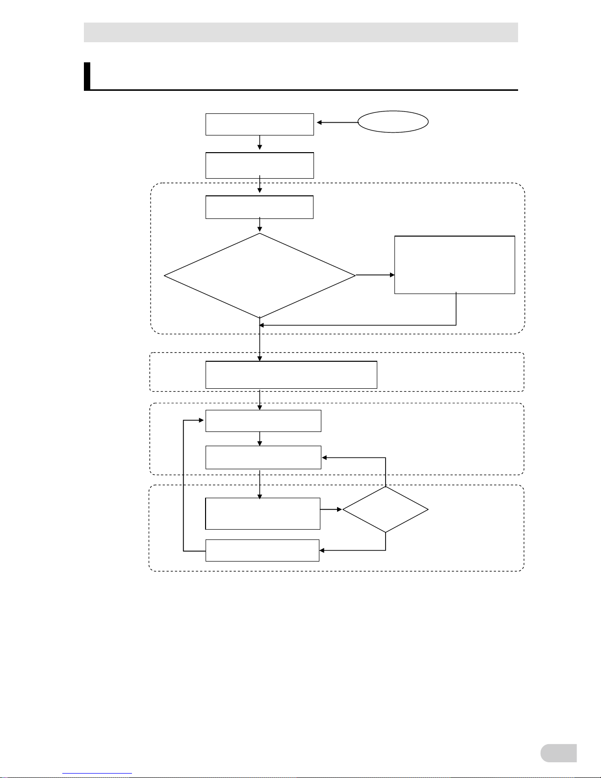
Procedure from installation to operation
The procedure from installation to operation is shown below.
Read “Safety precautions”
Page 7
Start
Remove the product from the
package and check the contents
1. Preparation
Perform installation and
connection
2. Installation and connection
Are you using either of the
following functions?
- UPS monitoring software
- Contact signal
- SNMP/Web card
Check the operation
3. Check and start operation
(Charge the battery *)
Operate
3. Check and start operation
Perform maintenance
and inspection
4. Maintenance and Inspection
Replace the battery
4.2 Replacing the battery
The battery must
be replaced
No
Yes
5.To perform shutdown processing
of the devices such as your PC
when a power failure occurs
6. Using contact signal functions
7. Using an SNMP/Web card
Yes
* The UPS has been charged prior to shipment.
However, if it is left for a long period of time, it
may have self-discharged.
We recommend charging the UPS before using it.
Installation/connection
Perform maintenance
and inspection
Preparation for operation
No
Operate

Table of Contents
BN50T/BN75T/BN100T/BN150T/BN220T/BN300T
4
Table of Contents
Introduction .................................................................................................. 1
IMPORTANT SAFETY INSTRUCTION ............................................................ 2
1. SAVE THESE INSTRUCTIONS. ............................................................ 2
2. SYMBOL ................................................................................................. 2
3. INTERNAL BATTERY............................................................................. 2
4. TEMPERATURE RATING ...................................................................... 2
5. ENVIRONMENT ..................................................................................... 2
Procedure from installation to operation
............................................................. 3
Table of Contents ........................................................................................ 4
Safety Precautions ....................................................................................... 7
1 Preparation ............................................................................................. 1-1
1-1 Unpacking the product ........................................................................... 1-1
1-2 Checking the contents ............................................................................ 1-1
1-3 Name of each part .................................................................................. 1-3
1-4 Diagram of the Input/output circuit block ................................................ 1-7
2 Installation and connection ..................................................................... 2-1
2-1 Installation .............................................................................................. 2-1
2-2 Connecting the equipment ..................................................................... 2-3
2-2-1 Connecting a device to the power supply output ................................ 2-3
2-3 Connecting the AC input ........................................................................ 2-5
2-3-1 Connecting the AC input plug ............................................................. 2-6
2-3-2 Connecting to BN220T/BN300T input terminal block .......................... 2-9
3 Check and start operation ...................................................................... 3-1
3-1 The name and function for the operation and display ............................ 3-1
3-1-1 Name of each part .............................................................................. 3-1
3-1-2 The meaning of each LED .................................................................. 3-1
3-1-3 Switch ................................................................................................. 3-2
3-1-4 Beep sound ......................................................................................... 3-3
3-1-5 LCD status screen .............................................................................. 3-4
3-1-6 Status screen example ....................................................................... 3-5
3-1-7 Icons, LEDs, and beeps. ..................................................................... 3-5
3-1-8 Lower message ................................................................................... 3-8
3-2 Checking the operation ........................................................................ 3-9

Table of Contents
BN50T/BN75T/BN100T/BN150T/BN220T/BN300T
5
3-3 Start and stop procedures and basic operation .................................... 3-11
3-3-1 Start and stop procedures ................................................................ 3-11
3-4 Operation from the LCD menu ............................................................. 3-13
3-4-1 The menu screen for the UPS settings ............................................. 3-13
3-4-2 The menu list of LCD ........................................................................ 3-15
4 Maintenance and Inspection .................................................................. 4-1
4-1 Checking the battery .............................................................................. 4-1
4-1-1 Check the display on the estimated life expectancy of the battery ..... 4-1
4-1-2 Self-diagnosis test ............................................................................... 4-1
4-1-3 Estimated backup time ....................................................................... 4-2
4-2 Replacing the battery ............................................................................. 4-4
4-2-1 Notification that the battery needs to be replaced .............................. 4-4
4-2-2 Procedure for recycling the battery ..................................................... 4-5
4-3 Cleaning ............................................................................................... 4-17
5
To perform shutdown processing of the devices when a power failure occurs
..... 5-1
5-1 The outline on the UPS monitoring software .......................................... 5-1
5-1-1 UPS monitoring software function list ................................................. 5-1
5-1-2 The supported OS of the UPS monitoring software ........................... 5-3
5-2
When using the included UPS monitoring software
................................... 5-4
5-2-1 What is the PowerAct Pro ................................................................... 5-4
5-2-2 What is the Simple Shutdown Software.............................................. 5-4
5-2-3 How to connect ................................................................................... 5-4
5-3
When performing auto-save functions using the standard UPS service and the contact
signal card (SC07
)
...................................................................................... 5-7
6 Using the contact signal functions .......................................................... 6-1
6-1 Contact signal functions ......................................................................... 6-1
6-2 SC07 Contact signal card specifications ................................................ 6-1
6-2-1 Contact signal connector (female D-SUB 9pin) .................................. 6-2
6-2-2 Type of Input/Output signals ............................................................... 6-2
6-2-3 Contact Signal ratings ......................................................................... 6-3
6-2-4 Contact Signal circuit .......................................................................... 6-4
6-2-5 Example of the use of the Contact Signal circuit ................................ 6-4
6-2-6 Items that can be set using the contact signal card ............................ 6-5
6-2-7 Insert method of contact signal card ................................................... 6-5
6-3 Remote ON/OFF connector ................................................................... 6-6
6-3-1 Type of Input signal ............................................................................. 6-6
6-3-2 Remote ON/OFF connector ................................................................ 6-6

Table of Contents
BN50T/BN75T/BN100T/BN150T/BN220T/BN300T
6
6-3-3 Signal input circuit ............................................................................... 6-7
6-3-4 Remote ON/OFF circuit ...................................................................... 6-7
7 Using an SNMP/Web card ..................................................................... 7-1
7-1 Adding an SNMP/Web card ................................................................... 7-1
7-2 SNMP/Web card outline ......................................................................... 7-1
7-2-1 Description (features).......................................................................... 7-1
7-2-2 Specifications ...................................................................................... 7-2
8 Troubleshooting ..................................................................................... 8-1
9 Note of Chinese ..................................................................................... 9-1
10 References ........................................................................................ 10-1
10-1 Specifications ....................................................................................... 10-1
10-2 Dimensions .......................................................................................... 10-2
10-3 Battery life ............................................................................................ 10-4
10-4 Input voltage sensitivity settings ........................................................... 10-5
10-5 China RoHS Information ...................................................................... 10-6
保修单/保修协议条款
Safety Precautions
BN50T/BN75T/BN100T/BN150T/BN220T/BN300T
7
Safety Precautions
Safety precautions
Important information for safe operation is described.
Be sure to read it before installation and start of use.
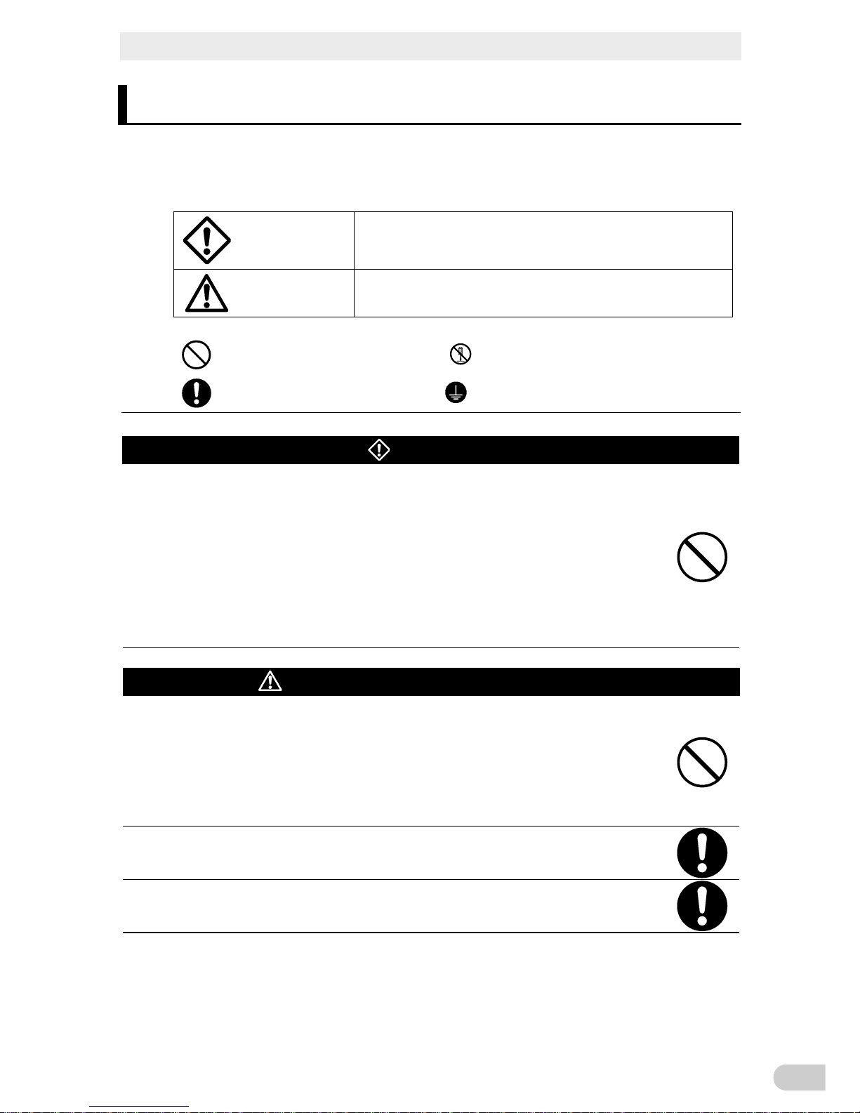
l The safety symbols and their meaning used in this manual are as follows:
Warning
Misuse may cause death or serious injury.
Caution
Misuse may cause injury or property damage.
* Property damage means damage to houses/household effects, livestock, and pets.
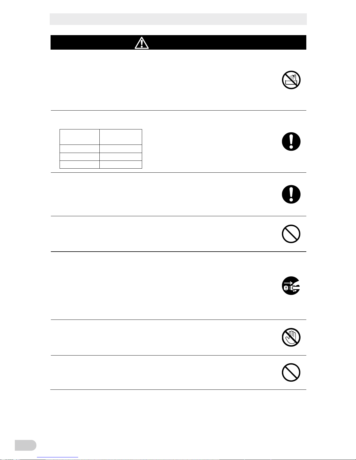
: Indicates prohibition. For example, indicates that disassembly is prohibited.
: Indicates obligation. For example, indicates that grounding is necessary.
Warning
Do not use this unit when very high reliability and safety are required as
listed below. This unit is designed and manufactured for use with FA or
OA equipment such as personal computers.
l Medical equipment or system that may cause death directly.
l Applications that directly affect the safety of people (For example, the operation and
control of cars and elevators).
l Applications in which a failure of the unit may cause significant damage to the society
and public (For example, essential computer systems and main communication
equipment.)
l Applications with the same level of importance.
Caution (for installation and connection)
Carry the unit considering its weight and balance, and place it on a stable
and robust base.
l Dropping or toppling the unit may cause injury.
l The approximate weight of the unit is 11 kg (BN50T/BN75T), 20 kg
(BN100T/BN150T), 36 kg (BN220T), or 37 kg (BN300T).
l If you drop the unit, stop using it and have it inspected and repaired.
For repair, contact the shop of purchase.
Do not hold the front panel when lifting.
l Injury may result if the panel comes off and falls.
Keep plastic package bags out of reach of children.
l Children may suffocate if they place their heads into plastic bags.
Warning
Do not use this unit when very high reliability and safety are required as
listed below. This unit is designed and manufactured for use with FA or
OA equipment such as personal computers.
● Medical equipment or system that may cause death directly.
● Applications that directly affect the safety of people (For example, the operation and
control of cars and elevators).
● Applications in which a failure of the unit may cause signicant damage to the society
and public (For example, essential computer systems and main communication
equipment.)
● Applications with the same level of importance.
Carry the unit considering its weight and balance, and place it on a stable
and robust base.
● Dropping or toppling the unit may cause injury.
● The approximate weight of the unit is 11 kg (BN50T/BN75T),
20 kg (BN100T/BN150T), 36 kg (BN220T), or 37 kg (BN300T).
● If you drop the unit, stop using it and have it inspected and repaired.
● For repair, contact the shop of purchase.
Do not hold the front panel when lifting.
● Injury may result if the panel comes off and falls.
Keep plastic package bags out of reach of children.
● Children may suffocate if they place their heads into plastic bags.
Caution
(for installation and connection)
Safety Precautions
BN50T/BN75T/BN100T/BN150T/BN220T/BN300T
8
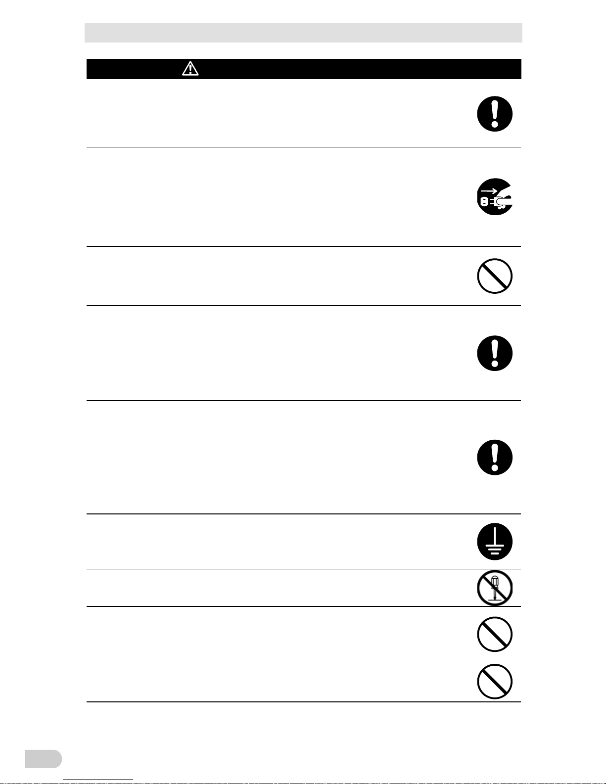
Caution (for installation and connection)
Make sure to connect the unit’s AC input plug to a commercial power
source with rated input voltage (100 VAC) and 50/60 Hz frequency.
Connecting to a commercial power source with a different rated input voltage or fre-
quency may result in a fire.
The unit may fail.
When an abnormality (unusual sound or smell) occurs, turn OFF the
unit’s power switch to stop the output, and stop the supply of commercial
power. Disconnect the AC input plug from the wall outlet.
The socket-outlet shall be installed near the equipment and shall be easily
accessible.
When performing maintenance on the connected devices, follow the above instruc-
tions to ensure safety.
Do not connect devices such as dryers, some solenoid valves, etc., which
have a half-wave rectifier that allows only half-cycle AC power to flow
through.
Overcurrent may damage the UPS.
Do not connect the maximum load when using the default AC plug with
BN150T or BN300T. (The default plug of BN150T: 15A/NEMA5-15P,
BN300T: 30A/NEMA L5-30P)
If the power consumption exceeds the limits shown in the table in "2-3 Connecting the
AC input", overheating or fire may occur.
If the maximum output capacity is being used, replace the plug as described in the
table in "2-3 Connecting the AC input".
When changing the input cable for the BN150T/BN220T/BN300T, perform
connection as specified.
Make sure to properly match the AC input terminal with the appropriate
wire color.
Do not perform work on the AC input terminal while the unit is connected
to a commercial power source.
Use an input cable that complies with the input current specification of the UPS.
Failure to do so may result in electric shock or ground fault.
Provide secure grounding.
After checking the plug shape of the wall outlet, directly connect the AC input plug of
the unit to it. A failure or leak that occurs when the unit is not properly grounded may
result in electric shock.
Do not disassemble, repair, or modify the unit.
Doing so may cause an electric shock or a fire.
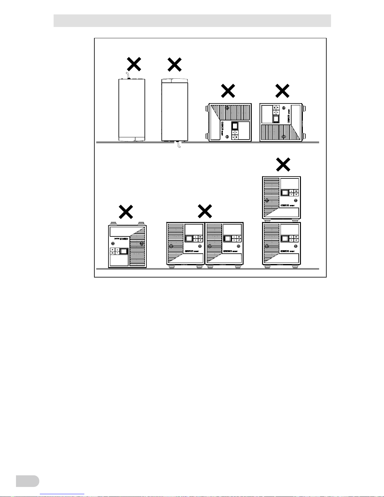
Do not install the unit in other than specified orientations.
Dropping or toppling the unit may cause injury.
If you install the unit in an orientation other than specified, the unit cannot be protected
from a battery fluid leakage.
Make sure to connect the unit’s AC input plug to a commercial power
source with rated input voltage (100 VAC) and 50/60 Hz frequency.
● Connecting to a commercial power source with a different rated input voltage or
frequency may result in a re.
● The unit may fail.
When an abnormality (unusual sound or smell) occurs, turn OFF the
unit’s power switch to stop the output, and stop the supply of commercial
power. Disconnect the AC input plug from the wall outlet.
The socket-outlet shall be installed near the equipment and shall be
easily accessible.
● When performing maintenance on the connected devices, follow the above
instructions to ensure safety.
Do not connect devices such as dryers, some solenoid valves, etc.,
which have a half-wave rectier that allows only half-cycle AC power to
ow through.
● Overcurrent may damage the UPS.
Do not connect the maximum load when using the default AC plug with
BN150T or BN300T. (The default plug of BN150T: 15A/NEMA5-15P,
BN300T: 30A/NEMA L5-30P)
● If the power consumption exceeds the limits shown in the table in "2-3 Connecting
the AC input", overheating or re may occur.
● If the maximum output capacity is being used, replace the plug as described in the
table in "2-3 Connecting the AC input".
When changing the input cable for the BN150T/BN220T/BN300T, perform
connection as specied.
Make sure to properly match the AC input terminal with the appropriate
wire color.
Do not perform work on the AC input terminal while the unit is connected
to a commercial power source.
● Use an input cable that complies with the input current specication of the UPS.
● Failure to do so may result in electric shock or ground fault.
Provide secure grounding.
● After checking the plug shape of the wall outlet, directly connect the AC input plug of
the unit to it. A failure or leak that occurs when the unit is not properly grounded may
result in electric shock.
Do not disassemble, repair, or modify the unit.
● Doing so may cause an electric shock or a re.
Do not install the unit in other than specied orientations.
● Dropping or toppling the unit may cause injury.
● If you install the unit in an orientation other than specied, the unit cannot be
protected from a battery uid leakage.
Do not use the unit where the maximum temperature exceeds 40°C.
● The battery deteriorates rapidly.
● Doing so may cause a failure or malfunction of the unit
Caution
(for installation and connection)
Safety Precautions
BN50T/BN75T/BN100T/BN150T/BN220T/BN300T
9
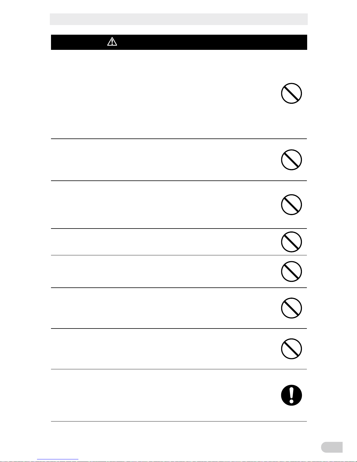
Caution (for installation and connection)
Do not use the unit where the maximum temperature exceeds 40°C.
l The battery deteriorates rapidly.
l Doing so may cause a failure or malfunction of the unit
Do not exceed the ranges specified for environmental conditions during
use/storage.
Do not install or store the unit in the places listed below.
l Do not store in places where the humidity is lower than 10% or higher than 90%.
l Do not use the unit in places where the ambient temperature is lower than 0°C or
higher than 40°C. (With no condensation)
l Do not use in places where the humidity is lower than 25% or higher than85%
l Do not install/store the unit in closed places such as cabinets with no clearance,
places where there is flammable or corrosive gas, places with large amounts of dust,
places exposed to direct sunlight,
places exposed to shock or vibration, salty or wet
places, or outdoors.
l Installation or storing the unit in such a place may cause a fire.
When you use plug strip and other plugs to connect additional devices, do
not connect devices that exceed the current capacity of the available plugs.
l The current protection of the unit may operate, which may stop the output.
l The wiring of the plug strip heats up, which may cause a fire.
Do not pinch or sharply bend the cable.
Do not fold or knot the cable.
l Doing so may cause the cable to be damaged or heated, which may cause an electric
shock or a fire.
l If the cable is damaged, stop using the unit and have the cable repaired.
l For repair, contact the shop of purchase.
All of the included accessories are designed to be used with the unit. Do
not use the accessories with other devices.
l Doing so may compromise the safety of devices.
Do not block the air vents (front, rear, and sides).
l Doing so will cause the internal temperature to rise, which may cause the unit to fail
and the battery to deteriorate.
l Leave at least 5 cm of space between the vent and the wall.
Do not connect a transformer such as a voltage transformer or isolating
transformer to the output side.
l Overcurrent may damage the UPS or cause it to malfunction.
l Even when connected to the input side, the UPS may fail or malfunction. Make sure to
check the operation before use.
Do not connect devices that cannot be used with commercial power supply.
l When the unit’s power switch is turned ON and an error occurs with the connected
device, bypass operation is performed and commercial power supply is supplied as is
to the connected devices.
Do not exceed the ranges specied for environmental conditions during
use/storage.
Do not install or store the unit in the places listed below.
● Do not store in places where the humidity is lower than 10% or higher than 90%.
● Do not use the unit in places where the ambient temperature is lower than 0°C or
higher than 40°C. (With no condensation)
● Do not use in places where the humidity is lower than 25% or higher than85%
● Do not install/store the unit in closed places such as cabinets with no clearance,
places where there is ammable or corrosive gas, places with large amounts of dust,
places exposed to direct sunlight, places exposed to shock or vibration, salty or wet
places, or outdoors.
● Installation or storing the unit in such a place may cause a re.
When you use plug strip and other plugs to connect additional devices,
do not connect devices that exceed the current capacity of the available
plugs.
● The current protection of the unit may operate, which may stop the output.
● The wiring of the plug strip heats up, which may cause a re.
Do not pinch or sharply bend the cable.
Do not fold or knot the cable.
● Doing so may cause the cable to be damaged or heated, which may cause an
electric shock or a re.
● If the cable is damaged, stop using the unit and have the cable repaired.
● For repair, contact us; ____
All of the included accessories are designed to be used with the unit.
Do not use the accessories with other devices.
● Doing so may compromise the safety of devices.
Do not block the air vents (front, rear, and sides).
● Doing so will cause the internal temperature to rise, which may cause the unit to fail
and the battery to deteriorate.
● Leave at least 5 cm of space between the vent and the wall.
Do not connect a transformer such as a voltage transformer or isolating
transformer to the output side.
● Overcurrent may damage the UPS or cause it to malfunction.
● Even when connected to the input side, the UPS may fail or malfunction. Make sure
to check the operation before use.
Do not connect devices that cannot be used with commercial power
supply.
● When the unit’s power switch is turned ON and an error occurs with the connected
device, bypass operation is performed and commercial power supply is supplied as
is to the connected devices.
An additional circuit breaker or fuse with breaking capacity 3kA shall be
used between power source and input when installation this unit.
(for BN50T, BN75T, BN100T, BN159T)
An additional circuit breaker or fuse with breaking capacity 6kA shall be
used between power source and input when installation this unit.
(for B N220T and BN300T)
Caution
(for installation and connection)
Safety Precautions
BN50T/BN75T/BN100T/BN150T/BN220T/BN300T
10
Caution (for use)
Do not allow the unit to come in contact with water.
If you drop the unit, stop using it.
l Doing so may cause an electric shock or a fire.
l If the unit becomes wet or is dropped, immediately stop using it, disconnect the AC
input plug from the wall outlet (commercial power source) and have it inspected and
repaired.
l For repair, contact the shop of purchase.
When the battery is dead, replace it immediately or stop using the unit.
l Continuing the use of it may cause fire or electric shock due to liquid leaks.
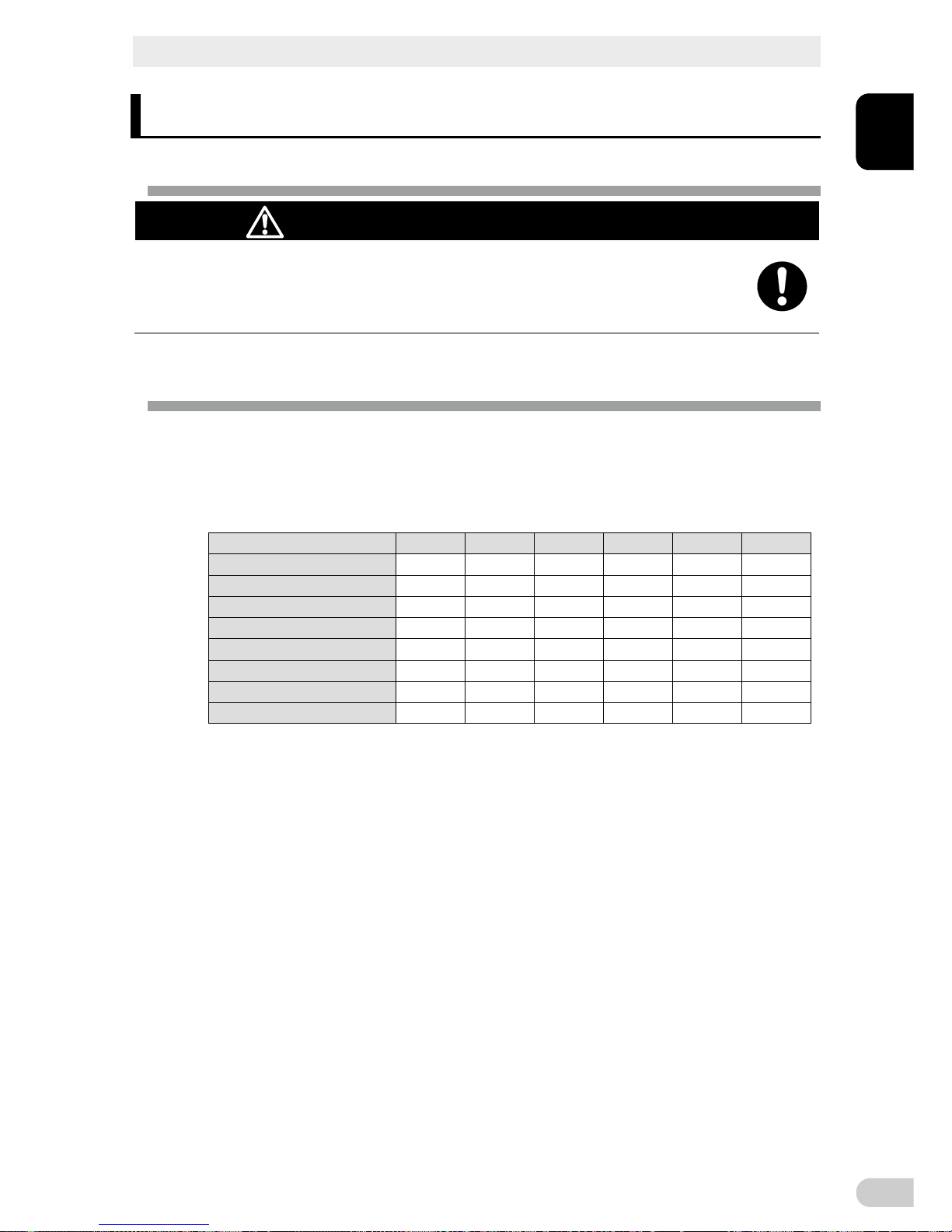
Ambient
temperature
Expected life
* The values in the table are the expected life under
standard use conditions and are not guaranteed.
40°C 2 years
30°C 4 years
25°C 5 years
Using a dry cloth, periodically wipe the dust from the AC input plug, input
terminal block and power supply output receptacles.
l Accumulated dust may cause a fire.
l Before wiping off dust, stop all connected devices and the unit, and disconnect the AC
input plug from the power socket (commercial power supply).
Do not use the unit in a closed place and do not cover the unit.
l Doing so may cause abnormal heating or a fire.
l Depending on the operating environment, hydrogen gas may be generated from the
battery, resulting in a rupture or explosion. Ventilate the area around the unit.
If you notice an abnormal sound or smell, smoke, or leaking fluid, immediately turn OFF the unit’s power switch and stop the supply of commercial power. Disconnect the AC input plug from the wall outlet.
l Using the unit under such conditions may cause a fire.
l If you notice such a condition, stop using the unit and contact the shop of purchase
for inspection and repairs.
l Position the unit in such a way that you can immediately disconnect the AC input plug
from the wall outlet (commercial power source) in the event a problem occurs.
If fluid (dilute sulfuric acid) leaks from the interior, do not touch the fluid.
l Doing so may cause blindness or burns.
l If the fluid contacts your eyes or skin, wash it out with lots of clean water and consult
your doctor.
Do not place objects heavier than 25 kg on the unit, and do not drop
heavy objects onto the unit.
l Doing so may cause distortion/damage to the case or a failure of the internal circuit,
which may cause a fire.
Safety Precautions
BN50T/BN75T/BN100T/BN150T/BN220T/BN300T
11
Caution (for use)
The unit is equipped with a bypass circuit which is able to supply electric
power to connected devices even when the inner control circuit is broken
down by defects or malfunctions.
If you want to stop the output, either stop the source of commercial power
or disconnect the AC input plug from the wall outlet (commercial power
source).
Output is continuing even when all indicators of the front panel are off.
Output ON/OFF cannot be controlled with the power switch on the front panel.
Do not sit or stand on top of the product, use it as a step ladder, or lean
against it.
Doing so may cause the unit to fail or to fall over and result in injury.
Caution (for maintenance)
When maintaining the connected equipment, turn OFF the unit’s power
switch to stop the output, and stop the supply of commercial power.
Even if commercial power to the UPS is stopped while it is in operation, the power
output of his unit does not stop and power is supplied from the receptacle.
Do not disassemble, repair, or modify the unit.
Doing so may cause an electric shock or a fire.
If fluid (dilute sulfuric acid) leaks from the interior, do not touch the fluid.
Doing so may cause blindness or burns.
If the fluid contacts your eyes or skin, wash it out with lots of clean water and consult your doctor.
Do not throw the unit into fire.
The lead battery in the unit may explode, or leak dilute sulfuric acid.
Do not insert metal objects into the power supply output receptacle of the UPS.
Doing so may result in electric shock.
Do not insert metal objects into the battery connectors.
Do not short between the connector terminals.
Doing so may result in electric shock.
Caution (for battery replacement)
Perform replacement on a stable and flat place.
Handle the battery carefully so that you do not drop it.
Risk of injury due to falling, or burns due to fluid leakage (dilute sulfuric acid).

Safety Precautions
BN50T/BN75T/BN100T/BN150T/BN220T/BN300T
12
Caution (for battery replacement)
Use a specified battery for replacement.
Not doing so may cause a fire.
Replacement battery pack for:
Product model:
BNB75T: One required (Replacement battery pack for BN50T/BN75T)
BNB300T: One required (Replacement battery pack for BN100T/BN150T)
BNB300T: Two required (Replacement battery pack for BN220T/BN300T)
Do not replace the battery in a place where there is flammable gas.
Spark may occur when connecting the battery, which may cause an explosion or fire.
Do not open or mutilate batteries.
Released electrolyte is harmful to the skin and eyes. It may be toxic.
Do not disassemble or modify the battery.
Doing so could cause dilute sulfuric acid leak, which could cause blindness and burns.
Do not drop the battery and do not expose it to strong impact.
Dilute sulfuric acid may leak.
Do not short the battery with metal objects.
Doing so could cause an electric shock, fire or burn.
Some electrical energy still remains inside the spent battery.
Do not dispose of batteries in a fire.
The batteries may explode.
Dispose of used batteries according to the instructions.
Do not use a new battery and an old battery at the same time.
Dilute sulfuric acid may leak.
A battery can present a risk of electrical shock and high short circuit current.
The following precautions should be observed when working on batteries:
a. Remove watches, rings, or other metal objects.
b. Use tools with insulated handles.
c. Wear rubber gloves and boots.
d. Do not lay tools or metal parts on top of batteries.
e. Disconnect charging source prior to connecting or disconnecting battery terminals.
f. Determine if battery is inadvertently grounded.
If inadvertently grounded, remove source from ground.
Contact with any part of a grounded battery can result in electrical shock.
The likelihood of such shock can be reduced if such grounds are removed during
installation and maintenance (applicable to equipment and remote battery supplies
not having a grounded supply circuit).
Servicing of batteries should be performed or supervised by personnel knowledgeable
of batteries and the required precautions.
Keep unauthorized personnel away from batteries.

Safety Precautions
BN50T/BN75T/BN100T/BN150T/BN220T/BN300T
13
ATTENTION
Ne pas ouvrir ni deteriorer les batteries.
Les fuites d'electrolyte sont dangereuses pour la peau et les yeux.
Proteger les batteries du feu. Risque d'explosion des batteries.
Utilisez les batteries conformement aux instructions.
Les batteries peuvent presenter un risque de choc electrique avec un fort courant de court circuit.
Les precautions suivantes doivent etre suivie lors de l'intervention sur les batteries :
a: retirer les montres, bagues et autre objets en metal
b: Utilisez des outils a manche isole
c: Utilisez des gants et des chaussures isolant
d: Ne pas laisser des outils ou des objets metalliques proches des batteries
e: Deconnecter le chargeur avant de connecter ou de deconnecter les batteries
f: determiner si la pile est mise a la terre. Si elle est mise a la terre, effectuer la deconnection. Le
contact avec une pile mise a la terre peut creer un choc electrique. Ceci sera reduit si cette mie
a
la terre est supprimee pendant installation et maintenance.
Notes
Before using
Charge the battery soon after purchasing the unit.
l If you do not use the unit for a long time after the purchase, the battery may dete-
riorate and the battery may become unusable.
l The battery can be charged once the AC input plug is connected to commercial
power.
When moving the unit from a cold place to a warm place, leave it for several
hours before using it.
l If the unit is promptly turned ON after being moved to a warmer place, condensa-
tion may form inside the unit and cause it to fail.
Take measures for handling unforeseen accidents, such as data backup and
system redundancy.
l The output may stop when there is failure in the UPS.
Connecting
Do not connect a page printer (such as a laser printer) to the unit.
l The unit repeatedly and frequently switches between Commercial Power Mode and
Battery Mode, which may shorten the life of the battery.
l The page printer has a large peak current, so an excess of the connection capacity
or a power failure due to instantaneous voltage drop may be detected.
Do not use the unit for an inductive device such as a coil or motor.
l With some types of devices, the effect of inrush current may cause this unit to stop
operating properly.

Safety Precautions
BN50T/BN75T/BN100T/BN150T/BN220T/BN300T
14
Check system operation beforehand if the unit is used in combination with a
device whose power supply voltage and frequency fluctuate widely, such as a
generator.
l If the generator’s output voltage/frequency falls out of the unit's input volt-
age/frequency range, the unit will enter Battery Mode.
Do not short the output lines of the unit to each other, and do not short the
output lines to the ground.
l The unit may fail.
In the event you transfer or sell this unit to a third party, please include all of the
documentation that came with the unit. This is to ensure that the unit is used in
line with the conditions described in the included documentation.
l This manual contains important safety-related information. Please read and under-
stand the contents of the manual before beginning operation. If this manual is misplaced, contact your dealer or download the manual from our website.
Using
Before stopping the commercial power to the unit, turn OFF the power switch of
the unit.
l The unit enters Battery Mode when commercial power is stopped.
Do not use for an application that frequently requires Battery Mode.
l The battery will deteriorate and fail to maintain the specified backup time.
Do not connect the AC input plug of the unit to its Power Supply Output Re-
ceptacle during the Battery Mode.
l The unit may fail.
This unit uses lead acid batteries.
l Which are a valuable recyclable resource. Please recycle.
Pb
Before performing a withstand voltage test or insulation resistance test, remove the input surge protection GND screw from the back of the unit.
When in use, make sure the input surge protection GND screw is securely fastened.
l Performing the withstand voltage test with the ground wire connected may damage
the surge absorption element built into the power supply input circuit.
Storing
Recharge the battery for at least 4 hours every 6 months when the storage temperature
is 25°C or less, or every 2 months when the storage temperature is 40°C or less.
l The battery self-discharges even when it not being used, and it goes into
over-discharge state if it is left for a long period of time. The backup time may become shorter or the battery may become unusable.
l
We recommend keeping the temperature 25°C or less when storing the unit for long periods of time.
l Turn OFF the unit’s power switch when storing it.
Do not install or store the unit in a place exposed to direct sunlight.
l The rise of temperature may cause the built-in battery to deteriorate rapidly and
become unusable.
1 Preparation
1-1 Unpacking the product
BN50T/BN75T/BN100T/BN150T/BN220T/BN300T
1
1-1
1 Preparation
1-1 Unpacking the product
Caution (for installation and connection)
The approximate weight of the unit is 11 kg (BN50T/BN75T), 20 kg
(BN100T/BN150T), 36 kg (BN220T), or 37 kg (BN300T). Note the weight
when unpacking and transporting the unit.
l Dropping may cause injury.
Open the package box and take out the UPS and accessories.
1-2 Checking the contents
Check whether all the package contents are included and there is no damage found on
their appearance.
If you should notice defects or anything wrong, contact the shop of purchase.
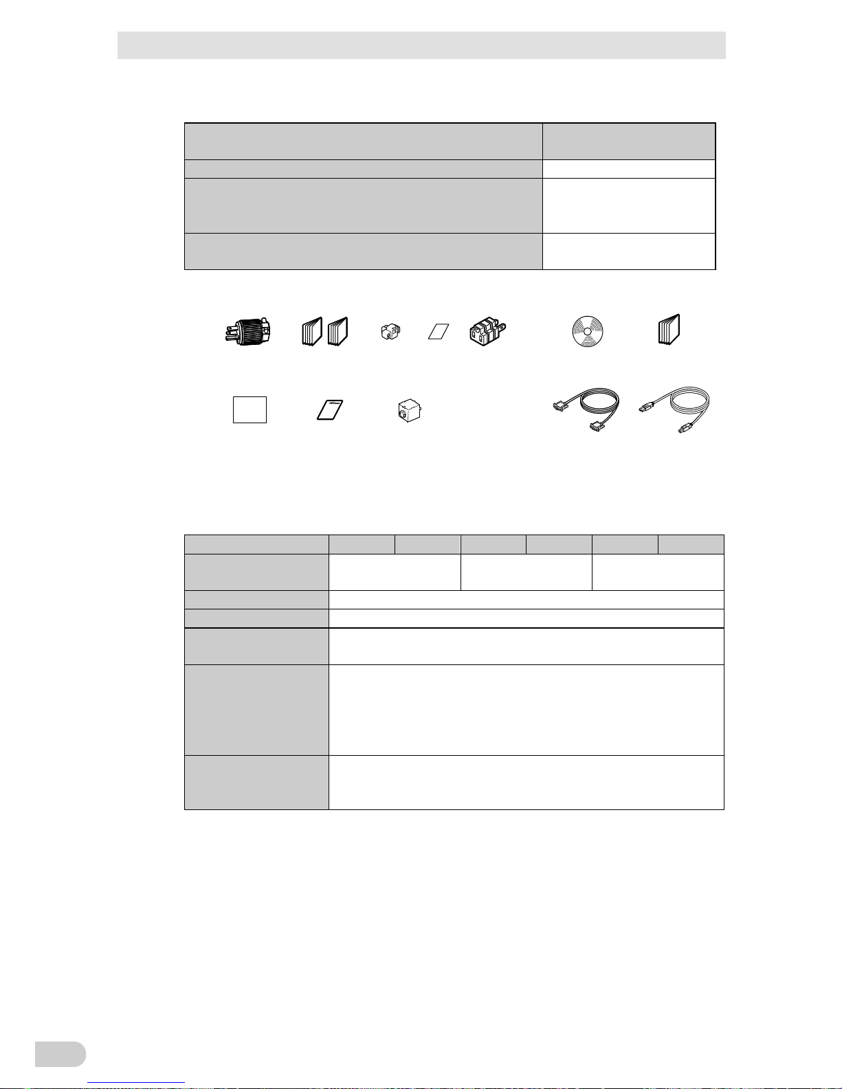
¢ Accessories related to the main unit
BN50T BN75T
BN100T BN150T BN220T BN300T
Manual (Japanese/English)
One each One each One each One each One each One each
Registration postcard/sheet
One each One each One each One each One each One each
Remote ON/OFF connector
1 1 1 1 1 1
Battery replacement date label
1 1 1 1 1 1
3P-2P conversion plug 1 1 1 1 - -
15A AC input plug for BN220T
- - - - 1 -
Serial number label 4 4 4 4 4 4
Input terminal block cover - - - - 1 set 1 set
1 Preparation
1-2 Checking the contents
BN50T/BN75T/BN100T/BN150T/BN220T/BN300T
1-2
UPS monitoring software related items
BN50T, BN75T, BN100T,
BN150T, BN220T, BN300T
Quick Install Guide 1
CD-ROM
"PowerAct Pro" UPS monitoring software, “Simple Shutdown
Software", and UPS service driver are included.
1
Connection cable (RS232C, USB)
cable length: 2.2m each
One each
Batter y
replacement
date label
3P-2P
conversion
plug
<Accessories related to main unit>
Serial number label
CD-ROM
Connection cable
(RS-232C)
(Approx. 2.2 m)
Connection cable
(USB)
(Approx. 2.2 m)
15A AC input plug
NEMA R5-15P
Input terminal
block cover
Registrati on
postcard/sheet
Manual
(Japanese/English)
Remote ON/OFF
connector
<UPS monitoring software>
Quick Installat ion Guide
Related products
BN50T BN75T BN100T BN150T BN220T BN300T
Replacement battery
pack
BNB75T BNB300T
BNB300T
(two required)
SNMP/Web card SC20G, SC20G2
Contact signal card SC07
Contact signal card
(relay output type)
SC08
Connection cable for
OS standard UPS
service with contact
signal card,
cable length: 2.2 m
BUC26
Extension cable for
RS-232C,
cable length: 4.5 m
BUC17
1 Preparation
1-3 Name of each part
BN50T/BN75T/BN100T/BN150T/BN220T/BN300T
1
1-3
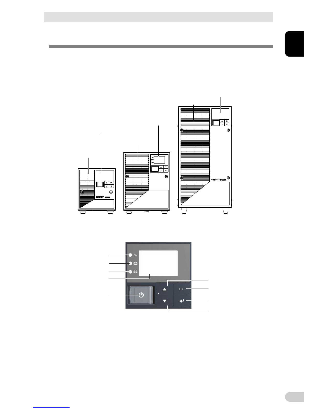
1-3 Name of each part
This section describes the name of each part of the UPS.
For information on the function of each part, refer to “2. Installation and connection” and “3.
Check and start operation” that provides the details.
Front view
<BN50T/BN75T>
<Enlarged view of the operation panel>
<BN100T/BN150T> <BN220T/BN300T>
(Air vent)
(Operation panel)
(Operation panel)
(Operation panel)
(Air vent)
(Air vent)
A
B
C
D
E
F
H
G
I
A. “Power supply output” LED
B. “Battery mode” LED
C. “Battery replacement” LED
D. Liquid Cell Display
E. “Power” switch
F. “Up” switch
G. “Down” switch
H. “ESC” switch
I. “Enter” switch
1 Preparation
1-3 Name of each part
BN50T/BN75T/BN100T/BN150T/BN220T/BN300T
1-4
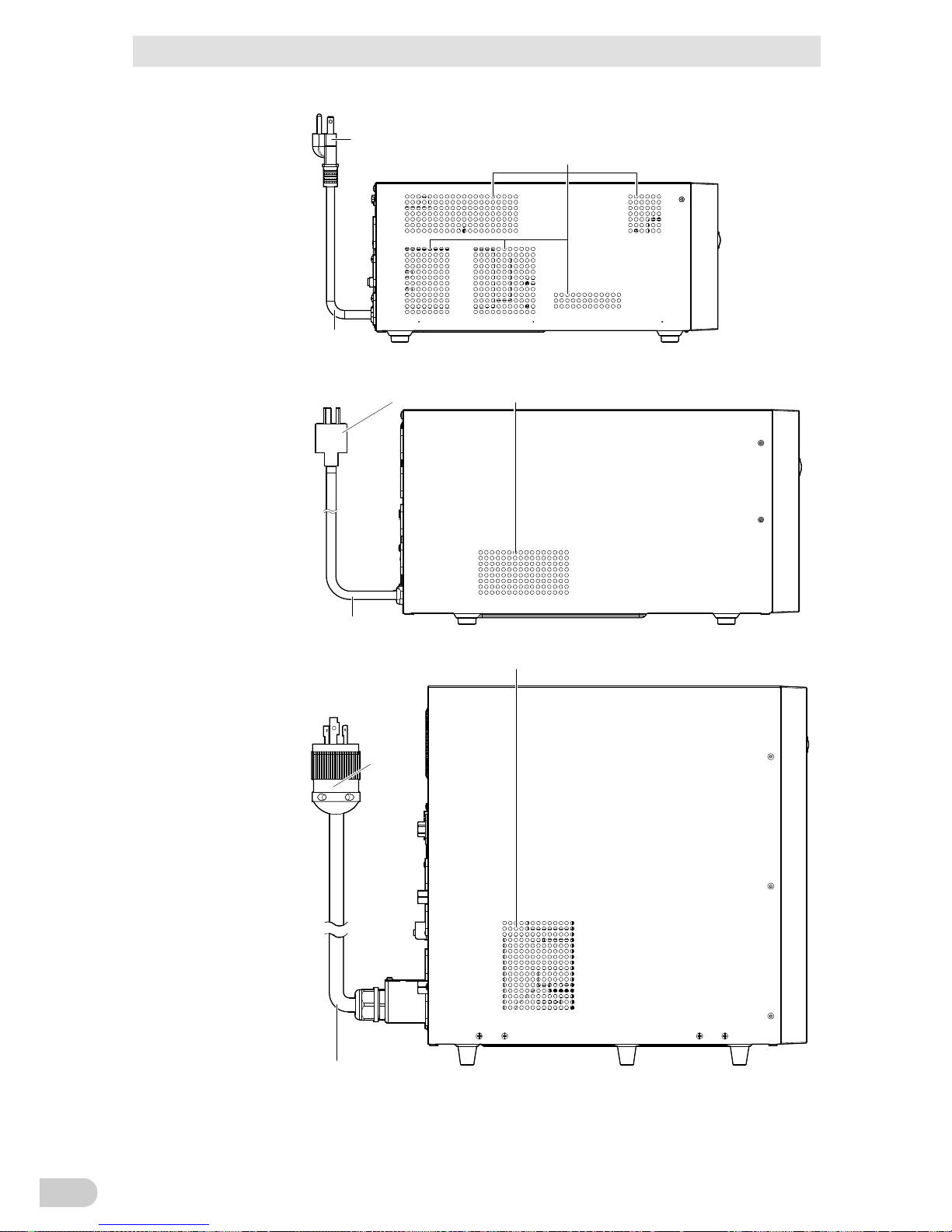
Side view
"AC Input" plug
Air vent
AC input cable
"AC Input" plug Air vent
AC input cable
AC input cable
"AC Input" plug
Air vent
<BN220T/BN300T>
<BN100T/BN150T>
<BN50T/BN75T>
*The other side (right side as seen from the front) has a similar air ven t.
*The other side (right side as seen from the front) has a similar air ven t.
1 Preparation
1-3 Name of each part
BN50T/BN75T/BN100T/BN150T/BN220T/BN300T
1
1-5
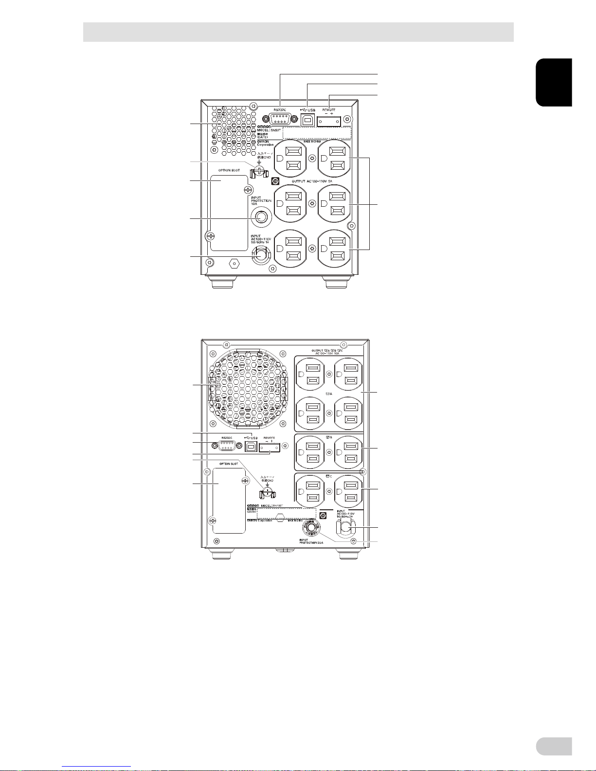
Rear view
<BN50T/BN75T>
<BN100T/BN150T>
D
E
F
I
G
C
B
A
K
C
H
I
J
A
B
G
D
E
F
H
I. Power supply output receptacle B
J. Power suppl y output receptacle C
K. Cooling fan
A. AC Input cable
B. AC Input overcurrent protection switch
C. Grou nding terminal (M4 screw)
D. RS-23 2C port
E. USB port
F. Remote ON/OFF port
G. Option slot
H. Power suppl y output receptacle A
G. Option slot
H. Power suppl y output receptacle
I. Air vent
A. AC Input cable
B. AC Input overcurrent protection switch
C. Grou nding terminal (M4 screw)
D. RS-232C port
E. USB port
F. Remote ON/OFF port
1 Preparation
1-3 Name of each part
BN50T/BN75T/BN100T/BN150T/BN220T/BN300T
1-6
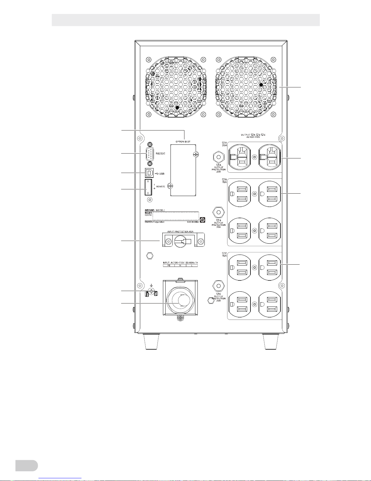
<BN220T/BN300T>
A. AC Input cable
B. AC Input overcurrent protection switch
C. Grounding terminal (M4 screw)
D. RS-232C port
E. USB port
F. Remote ON/OFF port
G. Option slot
H. Power supply output receptacle A
I. Power supply output receptacle B
J. Power supply output receptacle C
K. Cooling fan
BN220T
Use Copper Conductor Only.
Refer to the instruction manual
for the tightening torque.
入力サージ
保護GND
K
H
I
J
A
C
B
F
E
D
G
Left side: ON, right side: OFF
1 Preparation
1-4 Diagram of the Input/output circuit block
BN50T/BN75T/BN100T/BN150T/BN220T/BN300T
1
1-7
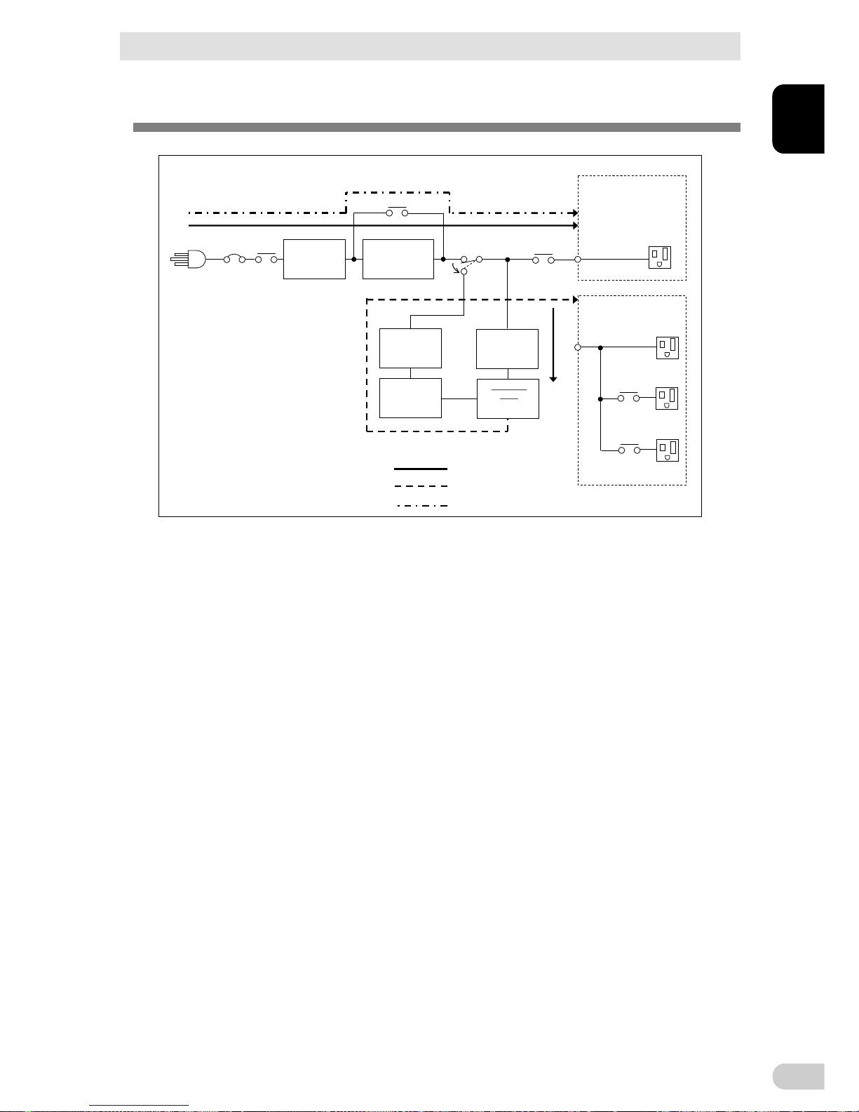
1-4 Diagram of the Input/output circuit block
Charger
Battery
DC-DC
converter
Inverter
AC100V input
Input overcurrent protection
Noise filter
Line mode
Battery mode
Bypass mode
AVR transforme
BN50T/BN75T:
without output receptacle
control
BN100T/BN150T/BN220T/
BN300T:
without output receptacl e control
Output group A
Output group B
Output group C
Power supply output receptacles

1 Preparation
BN50T/BN75T/BN100T/BN150T/BN220T/BN300T
1-8
2 Installation and connection
2-1 Installation
BN50T/BN75T/BN100T/BN150T/BN220T/BN300T
2
2-1
2 Installation and connection
2-1 Installation
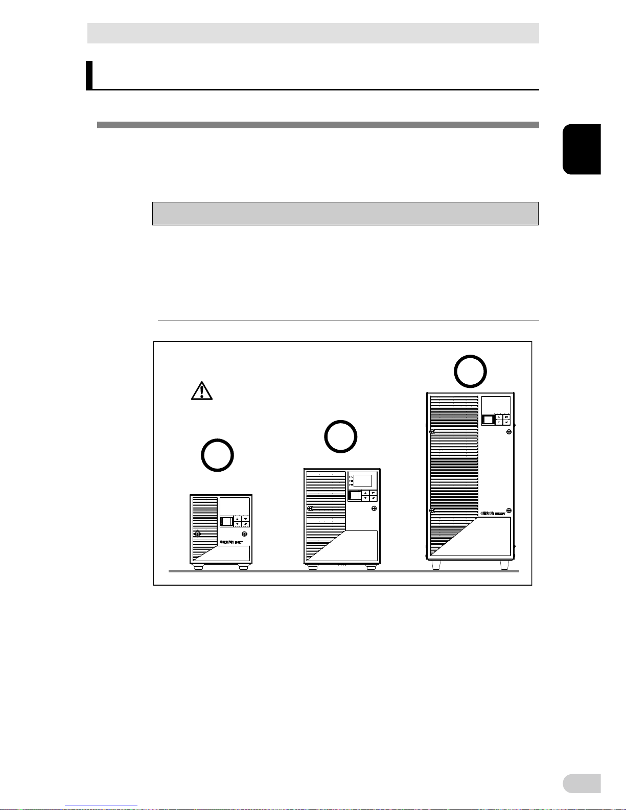
Install the UPS.
For cautions when installing the UPS, refer to “Caution (for installation and connection)”
shown in the "Safety precautions" of the beginning of this manual.
The UPS permits the following installing methods. Choose the one best suited for the
environment.
Note
Before installing this device, make a record of the serial number of this device.
The product serial number is required when contacting us about the device.
The serial number (S/N) is inscribed on the bottom left side of the rear panel.
The product serial number is inscribed on the bottom left side of the rear panel.
The product serial number label is also included.
Allow sufficient space at the back for the AC input cables of the UPS unit and con-
nected devices.
Correct Positions
Be careful not to get your fingers caught
when arranging the unit.
2 Installation and connection
2-1 Installation
BN50T/BN75T/BN100T/BN150T/BN220T/BN300T
2-2
Incorrect Positions
2 Installation and connection
2-2 Connecting the equipment
BN50T/BN75T/BN100T/BN150T/BN220T/BN300T
2
2-3
2-2 Connecting the equipment
Caution (for connection)
Do not connect devices, rated voltage is not 100V AC.
The rated output voltage of this device is 100 VAC.
Overcurrent may damage the connected devices.
2-2-1 Connecting a device to the power supply output
For cautions when connecting the UPS, refer to “Caution (for installation and connection)”
shown in the “Safety precautions” of the beginning of this manual.
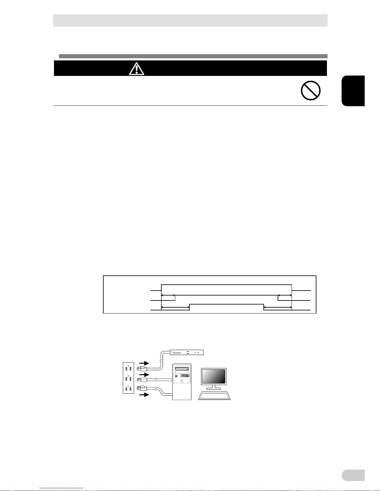
Control by group of “power supply output” (BN100T/BN150T/BN220T/BN300T only)
The output receptacles of the UPS (BN-T) are separated into 3 groups: A,
B, and C.
The output start times for power supply output group B and C are independent of
power supply output group A, so they can be delayed or set to precede the output
stop time.
The output start/stop time control function is available with the setting on the LCD
panel or when using the “PowerAct Pro” UPS monitoring software (included software) or “SNMP/Web card” (sold separately).
Output ON/OFF can be controlled by operating the LCD panel or with the included
“PowerAct Pro” UPS monitoring software while the UPS is operating.
The delay settings and ON/OFF control described here can be performed inde-
pendently for power supply output group B and power supply output group C.
This function can be used to set the startup order of servers, peripheral devices, etc.
The output receptacles can also be forcibly turned ON/OFF remotely.
Power supply ou tput group A
Power supply ou tput group B
Power supply ou tput group C
Output ON Output OFF
Time setting
Time setting
Time setting
Time setting
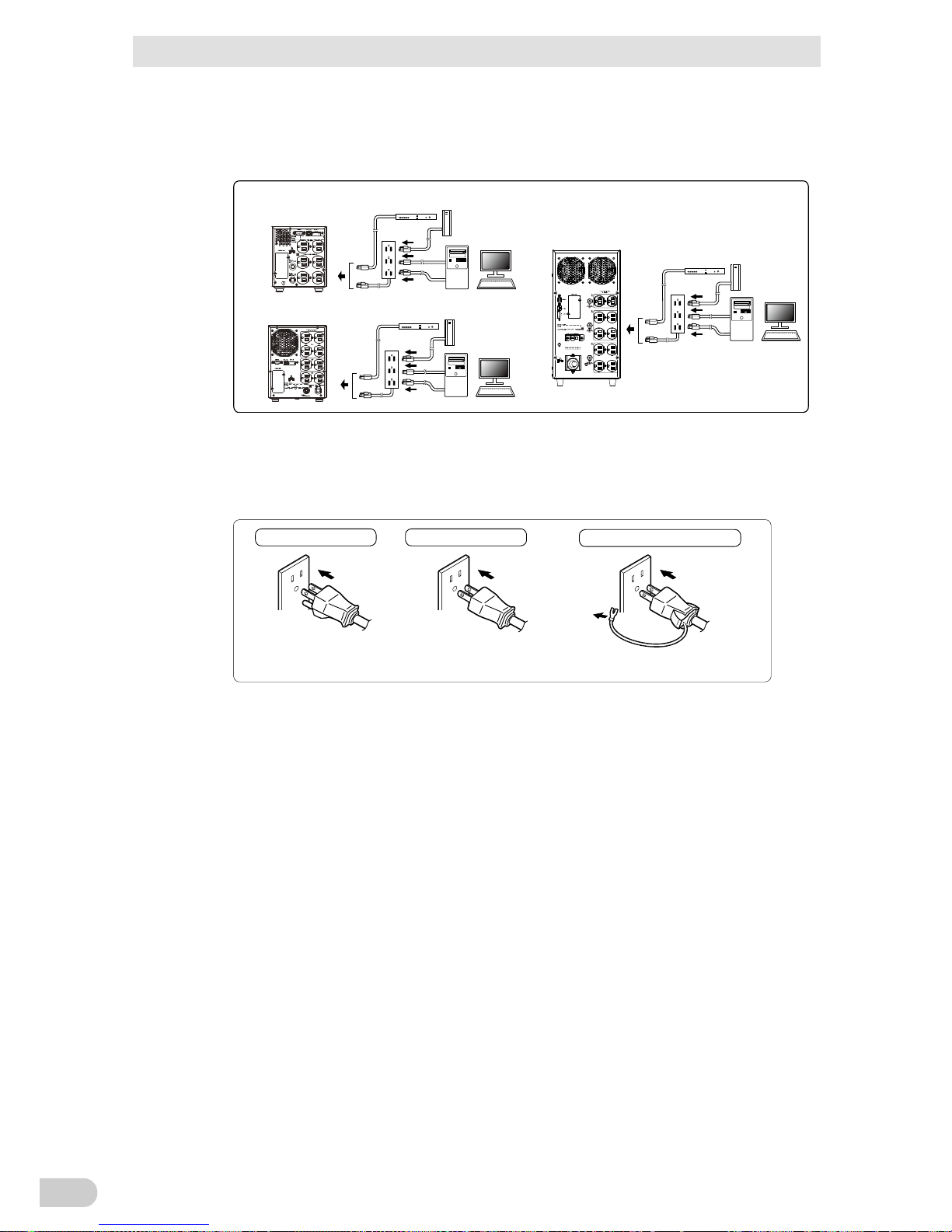
1. Disconnect the AC Input Plugs of all devices you want to back up such as your PC and
modems from a wall outlet (commercial power source).
PC
Wall outlet
(commercial power source)
Computer peripheral devices
2 Installation and connection
2-2 Connecting the equipment
BN50T/BN75T/BN100T/BN150T/BN220T/BN300T
2-4
2.
Connect devices you want to back up to the Power Supply Output Receptacles of the UPS.
If you need more output receptacles than those of the UPS, purchase a plug strip
and use it for extra output receptacles.
BN220T/BN300T
Computer peripheral dev ices
BN100T/BN150T
Computer peripheral dev ices
Exter nal HDD
Computer peripheral devi ces
Exter nal HDD
BN50T/BN75T
External HDD
BN50T
入力サージ
保護GND
BN100T
入力サージ
保護GND
BN220T
Use Copper Conductor Only.
Refer to the instruction manual
for the tightening torque.
入力サージ
保護GND
When the connected device has a 2-pin AC input plug, it can be connected directly
to the power supply output receptacle. When using a 2-pin input plug with a
grounding wire, connect the grounding wire to earth in building.
When you want to use an AC adaptor, connect it to a Power Supply Output Re-
ceptacle of the UPS with space enough for the connection.
Plug of connected device
Plug of connected device
Plug of connected device
Connect the plug directly.
Connect the grounding wire to the
earth terminal of the UPS.
Connect the grounding wire of
connect devices to earth of the
UPS.
Connect it directly.
Connect it directly.
3. When using the included UPS monitoring software, the Windows standard UPS service,
or the contact signal, use the connection cable to connect the unit to the PC.
See also "5. To perform shutdown processing of the devices such as your PC when a
power failure occurs", and "6. Using contact signal"
Note:
If you do not use the UPS monitoring software and Contact Signal, this step is not required.
2 Installation and connection
2-3 Connecting the AC input
BN50T/BN75T/BN100T/BN150T/BN220T/BN300T
2
2-5
2-3 Connecting the AC input
When installation and connection are complete, connect the unit’s AC input to a
commercial power source.
Caution (for connection)
Make sure to connect the AC input plug of the unit into a wall outlet
(commercial power source) with rated input voltage of 100V AC.
Connecting to a wall outlet (commercial power source) of a different rated voltage may
result in fire.
The unit may fail.
The BN50T/BN75T/BN100T AC input plug cannot be changed.
The AC input plug for the BN150T/BN220T/BN300T can be changed according to
the operating environment.
The supported AC input plugs and the maximum connection capacities are as follows.
Change to an appropriate AC input plug according to the connection capacity of the
device.
The changed plug must be UL list product, and the plug should be meet the UPS
application, please refer to the plug installation instructions.
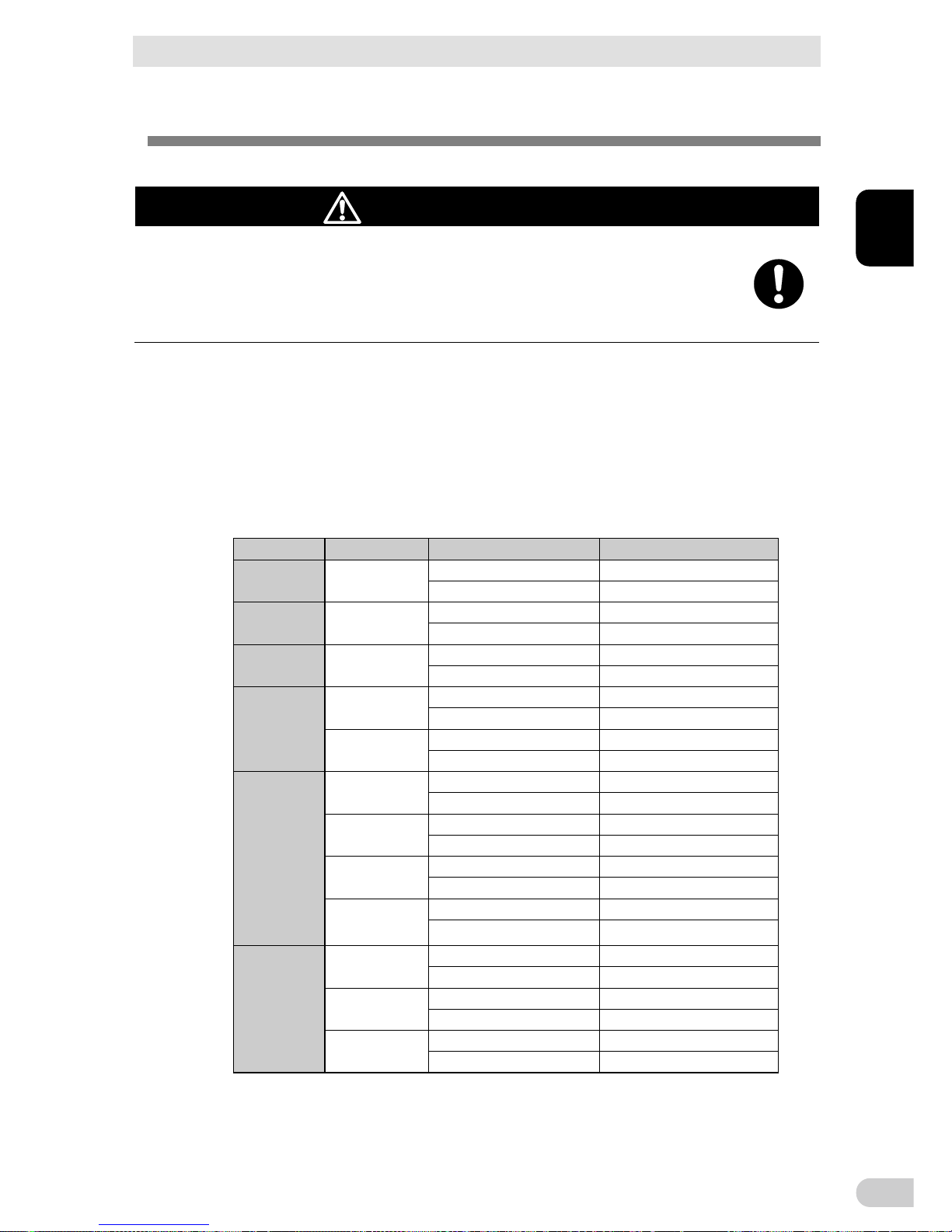
Model AC input plug
AC input plug Sensitivity setting
Maximum connection capacity
BN50T 15A(*)
Low 500VA/450W
Standard(*)/High 500VA/450W(*)
BN75T 15A(*)
Low 750VA/680W
Standard(*)/High 750VA/680W(*)
BN100T 15A(*)
Low 1000VA/900W
Standard(*)/High 1000VA/900W(*)
BN150T
15A(*)
Low 1050VA/1050W
Standard(*)/High 1125VA/1125W(*)
20A
Low 1450VA/1350W
Standard/High 1500VA/1350W
BN220T
15A
Low 1020VA/1020W
Standard/High 1095VA/1095W
20A
Low 1420VA/1420W
Standard/High 1520VA/1520W
30A(*)
Low 2050VA/1980W
Standard(*)/High 2200VA/1980W(*)
Terminal block
Low 2200VA/1980W
Standard/High 2200VA/1980W
BN300T
20A
Low 1420VA/1420W
Standard/High 1520VA/1520W
30A(*)
Low 2220VA/2220W
Standard(*)/High 2370VA/2370W(*)
Terminal block
Low 3000VA/2700W
Standard/High 3000VA/2700W
* The bold font indicates factory settings.
2 Installation and connection
2-3 Connecting the AC input
BN50T/BN75T/BN100T/BN150T/BN220T/BN300T
2-6
Caution (for connection)
When the maximum output capacity (1500VA/1350W) is connected to the
BN150T, replace the AC input plug with a 20A plug. When the maximum
output capacity (3000VA/2700W) is connected to the BN300T, change to
terminal block connection.
Overheating or fire may occur if the power consumption exceeds the limits shown in
"2-3 Maximum connection capacities".
To reduce the risk of fire, unit input connect only to a circuit provided with branch
circuit 40 A overcurrent protection for BN220T, BN300T in accordance with the National Electric Code, "ANSI/NFPA 70".
If the maximum output capacity will be used, refer to "2-3 Maximum connection
capacities" chart to change the AC input connection method.
After changing the AC input plug, change the “Setting” - “In/Out Settings” - “Input Plug”
setting in the menu on the LCD.
Make sure that the connecting work is performed by a qualified electrical
engineer (with Type II certification or higher).
2-3-1 Connecting the AC input plug
BN50T/75T connection procedure
Provide a wall outlet (commercial power source) suitable for the shape of the 15A plug
(NEMA 5-15R).
It is possible to connect to a 2-pin outlet using the included 3P-2P adapter.
Note: In this case, provide grounding separately.
BN150T connection procedure
When using the 15A plug (connected when shipped)
- Provide a wall outlet (commercial power source) suitable for the shape of the 15A plug
(NEMA 5-15R).
- It is possible to connect to a 2-pin outlet using the included 3P-2P adapter.
Note: In this case, provide grounding separately.
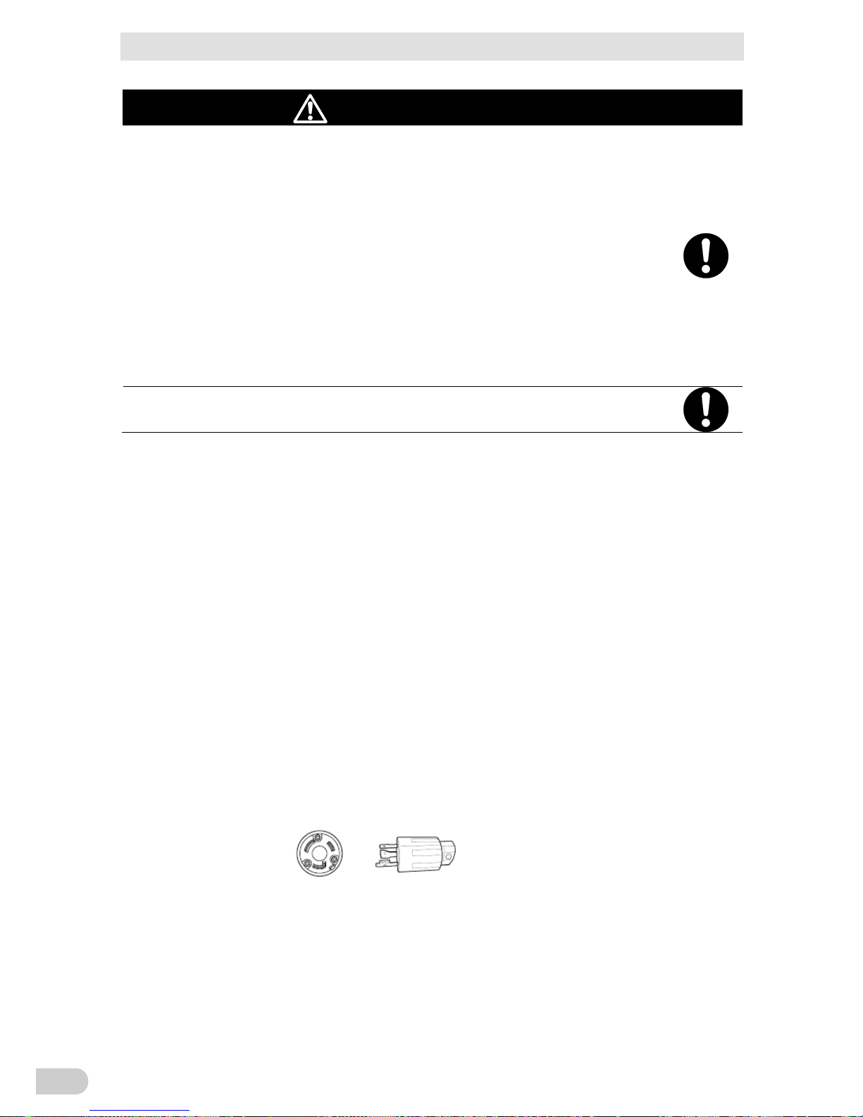
When using the 20A plug
You can use up to the rated capacity of the BN150T.
- Provide a wall outlet (commercial power source) suitable for the shape of the 20A plug
(NEMA 5-20R).
- Replace the AC input plug with the NEMA L5-20P plug.
 Loading...