

Uninterruptible Power Supply UPS
BA75T/BA100T/BA100R
Instruction Manual
BA75T/BA100T BA100R
・
This manual provides important safety-
related information. Thoroughly read and understand this
manual before installing and using the product.
・ Keep this manual in a convenient location so that you can refer to it whenever necessary.
・ The contents of this manual are subject to change without notice.
・ The warranty is included with the product.
使用说明书
中文使用说明书请参照“
8 Note of Chinese”。

Introduction
Introduction
Features of this product
Thank you for purchasing Omron's Uninterruptible Power Supply (UPS).
● The UPS protects computers and other devices from power failures, voltage variations,
instantaneous voltage drops, and surge voltage such as that caused by lightning (a phenomenon
in which extraordinary high voltage occurs instantaneously).
● Under normal conditions, commercial power is converted to direct current, and then it is converted
back to a stable sine wave AC power before it is output.
When a commercial power failure is detected, the unit switches to battery supply to provide
continuous sine wave output. This is especially suitable for use where power supply conditions are
poor (for example, when there are large variations in voltage)
● Output capacity is 750VA/600W for BA75T, 1000VA/800W for BA100T/BA100R.
Notes on the use of the Backup Power Supply
● This product is designed and manufactured for use with FA or OA equipment.
Do not use it when very high reliability and safety are required as listed below.
・ Medical equipment that may cause death directly
・ Applications that may cause injury (applications that directly affect the operation and control of
planes, ships, railroads and so on)
・ Applications that are always subjected to vibration such as cars and ships
・ Applications in which a failure of this product may cause significant damage or effect to the society
and public (important computer systems, main communication equipment, public transportation
systems and so on)
・ Equipment with the same level of importance
● For equipment that greatly affects the safety of people and maintaining public functions, special
considerations related to operation, maintenance, and management must be taken such as
duplicating the system and emergency power generation facilities.
● Observe the contents of this manual such as the use conditions and environments.
● When you want to use this product for an important system that requires very high reliability,
contact us.
● Do not modify/alter this product.
Disclaimers
We are not liable for any damage or secondary damage resulting from the use of our product,
including malfunction and failure of equipment, connected devices, or software.
Make sure to read the safety precautions before using the unit.
● In the event you transfer or sell this unit to a third party, please include all of the documentation
that came with this unit. This is to ensure that the unit is used in line with the conditions described
in the included documentation.
● This manual contains important safety-
related information. Please read and understand the
contents of the manual before beginning operation.
If you discover any omissions or errors in the manual, please contact the shop of purchase.
● Windows is the registered trademark of Microsoft Corporation in the United States and/or other
countries.
● The names of other companies and products mentioned herein are the trademarks or registered
trademarks of their respective owners.
©OMRON Corporation. 2015 All Rights Reserved
BA75T/BA100T/BA100R
1
Introduction
IMPORTANT SAFETY INSTRUCTION
1. SAVE THESE INSTRUCTIONS.
This manual contains important instructions for BA75T/BA100T/BA100R that should be followed
when using the UPS and batteries.
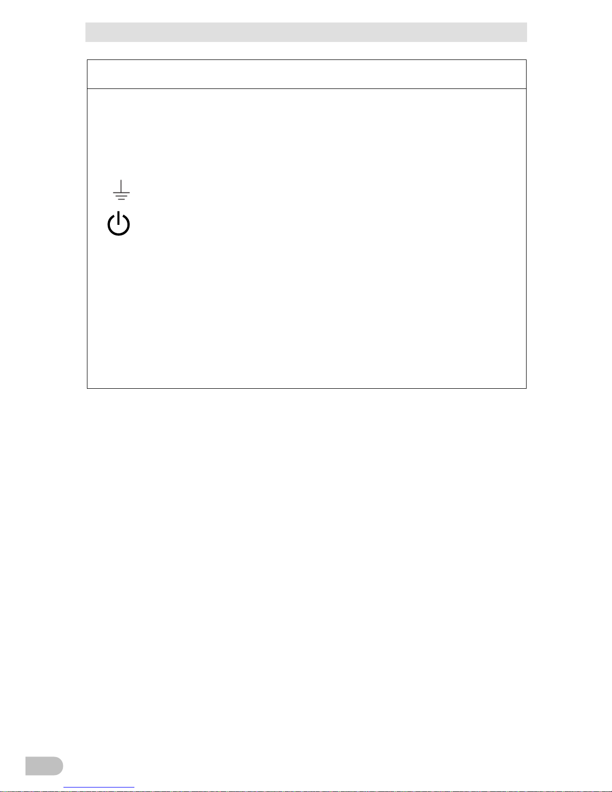
2. SYMBOL
This symbol indicates earth ground.
This symbol indicates turning on/off UPS.
3. INTERNAL BATTERY
Internal battery voltage is 24VDC for BA75T/BA100T/BA100R.
4. TEMPERATURE RATING
The maximum ambient temperature of the UPS is 40°C.
5. ENVIRONMENT
The unit is intended for installation in a temperature controlled, indoor area free of conductive
contaminants.
BA75T/BA100T/BA100R
2
Procedure from installation to operation
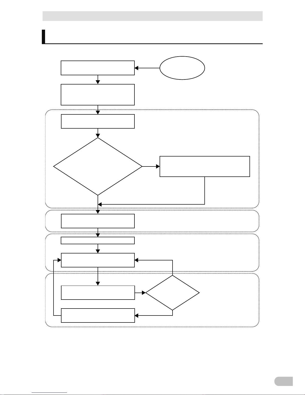
Procedure from installation to operation
The procedure from installation to operation is shown below.
Start
Read “Safety precautions”
Page 7
Remove the product from the
package and check the contents
1. Preparation
Perform installation and connection
2. Installation and connection
Are you using either of the
following functions?
- UPS monitoring software
- Contact signal
5. To perform shutdown processing of the
devices when a power failure occurs
6. Using the contact signal functions
Check the operation
3. Check and start operation
(Charge the battery *)
Operate
3. Check and start operation
* The UPS has been charged prior to shipment.
However, if it is left for a long period of time, it
may have self-discharged.
We recommend charging the UPS before using it.
Perform maintenance and inspection
4. Maintenance and Inspection
Replace the battery
4.2 Replacing the battery
The battery must
be replaced
Installation/connection
Preparation for operation
Operate
Perform maintenance
and inspection
Yes
No
No
Yes
BA75T/BA100T/BA100R
3

Table of Contents
Table of Contents
Introduction .................................................................................................. 1
Procedure from installation to operation
............................................................. 3
Table of Contents ......................................................................................... 4
Safety Precautions ....................................................................................... 7
1 Preparation ........................................................................................... 16
1-1 Unpacking the product .................................................................................... 16
1-2 Checking the contents .................................................................................... 16
1-3 Related products ............................................................................................. 17
1-4 Name of each part .......................................................................................... 18
1-5 Diagram of the Input/output circuit block ........................................................ 20
2 Installation and connection ................................................................... 21
2-1 Installation ....................................................................................................... 21
2-1-1 Rackmount installation (EIA/JIS 19-inch rack/server rack) ................................................ 24
2-1-2 Stationary installation ......................................................................................................... 27
2-2 Connecting the equipment .............................................................................. 29
2-2-1 Connecting a device to the power supply output ............................................................... 29
2-3 Connecting the AC input ................................................................................. 31
2-3-1 Connecting to the input terminal block ............................................................................... 31
3 Check and start operation .................................................................... 34
3-1
The name and function for the operation and display
............................................ 34
3-1-1 Name of each part ............................................................................................................. 34
3-1-2 The meaning of each LED ................................................................................................. 34
3-1-3 Switch ................................................................................................................................ 35
3-1-4 Setting Switch .................................................................................................................... 35
3-1-5 Beep sound........................................................................................................................ 40
3-2 Checking the operation ................................................................................... 41
3-3 Start and stop procedures and basic operation .............................................. 44
3-3-1 Start and stop procedures .................................................................................................. 44
3-4 Interpreting beeps and displays ...................................................................... 46
3-4-1 Displays and beeps in normal operations .......................................................................... 46
3-4-2 Displays and beeps while testing ....................................................................................... 47
3-4-3 Displays and beeps during power failure or AC input error ................................................ 47
BA75T/BA100T/BA100R
4

Table of Contents
3-4-4 Displays and beeps when there is an equipment failure .................................................... 48
3-4-5 Display and beep for battery replacement ......................................................................... 50
3-5 UPS operation mode settings ......................................................................... 51
3-5-1 Settable items and explanations ........................................................................................ 51
3-5-2 Settings .............................................................................................................................. 53
4 Maintenance and Inspection ................................................................. 57
4-1 Checking the battery ....................................................................................... 57
4-1-1 Battery life expectancy ....................................................................................................... 57
4-1-2 Self-diagnosis test ............................................................................................................. 57
4-1-3 Estimated backup time ...................................................................................................... 58
4-2 Replacing the battery ...................................................................................... 60
4-2-1 Notification that the battery needs to be replaced .............................................................. 61
4-2-2 Procedure for replacing the battery .................................................................................... 62
4-3 Replacing the fan ............................................................................................ 71
4-3-1 Fan replacement procedure ............................................................................................... 72
4-4 Cleaning .......................................................................................................... 76
5 To perform shutdown processing of the devices when a power failure occurs
....................... 77
5-1 The outline on the UPS monitoring software .................................................. 77
5-1-1 UPS monitoring software function list ................................................................................ 77
5-1-2 The supported OS of the UPS monitoring software ........................................................... 79
5-2 When using the UPS monitoring software ...................................................... 79
5-2-1 What is the PowerAct Pro .................................................................................................. 79
5-2-2 What is the Simple Shutdown Software ............................................................................. 80
5-2-3 How to connect .................................................................................................................. 80
6 Using the contact signal functions ........................................................ 82
6-1 Contact signal functions .................................................................................. 82
6-1-1 Type of Output signals ....................................................................................................... 82
6-1-2 Type of Input signals .......................................................................................................... 82
6-1-3 Contact signal port (female D-SUB 9 pin) .......................................................................... 83
6-1-4 Remote ON/OFF port ........................................................................................................ 83
6-1-5 Contact Signal ratings ........................................................................................................ 83
6-1-6 Contact Signal circuit ......................................................................................................... 83
6-1-7 Example of the use of the Contact Signal circuit ................................................................ 84
6-1-8 Precautions and notes for the use of the Contact Signal ................................................... 84
BA75T/BA100T/BA100R
5

Table of Contents
7 Troubleshooting .................................................................................... 85
8 Note of Chinese .................................................................................... 86
9 References ........................................................................................... 95
9-1 Specifications .................................................................................................. 95
9-2 Dimensions ..................................................................................................... 96
9-3 Battery life ..................................................................................................... 101
9-4 China RoHS Information ............................................................................... 102
BA75T/BA100T/BA100R
6

Safety Precautions
Safety Precautions
Safety precautions
Important information for safe operation is described.
Be sure to read it before installation and start of use.
● The safety symbols and their meaning used in this manual are as follows:
Warning
Misuse may cause death or serious inj ury.
Caution
Misuse may cause injury or property damage.
* Property damage means damage to houses/household effects, livestock, and pets.
: Indicates prohibition. For example,
indicates that disassembly is prohibited.
: Indicates obligation. For example,
indicates that grounding is necessary.
Note that events categorized as a caution required matter also may cause more serious results
under certain conditions.
Warning
(for use of this product)
Do not use this unit when very high reliability and safety are required as
listed below. This unit is designed and manufactured for use with FA or
OA equipment such as personal computers.
● Medical equipment or system that may cause death directly.
● Applications that directly affect the safety of people (For example, the operation and
control of cars and elevators).
●
Applications in which a failure of the unit may cause significant damage to the
society and public.
(For example, essential computer systems and main
communication equipment.)
●
Applications with the same level of importance.
This is a category C2 UPS product. In a residential environment, this
product may cause radio interference, in which case the user may be
required to take additional measures.
This is a Class A product based on the standard of the VCCI Council. If
this equipment is used in a domestic environment, radio interference
may occur, in which case, the user may be required to take corrective
actions.
BA75T/BA100T/BA100R
7
Safety Precautions
Caution
(for installation and connection)
Carry the unit consider
ing its weight and balance, and place it on a
stable and robust base.
● Dropping or toppling the unit may cause injury.
● The approximate weight of the unit is 12.5 kg (BA75T/BA100T), 13 kg (BA100R).
● If you drop the unit, stop using it and have it inspected and repaired.
For repair, contact us.
Keep plastic package bags out of reach of children.
● Children may suffocate if they place their heads into plastic bags.
Make sure to connect the unit’s AC input to a commercial power source
with rated input
voltage (100 VAC,110VAC,115VAC,120VAC) and 50/60 Hz
frequency.
●
Connecting to a commercial power source with a different rated input voltage or
frequency may result in a fire.
●
The unit may fail.
When an abnormality (unusual sound or smell) occurs, t
urn OFF the
unit’s “Power” switch
to stop the output, and stop the supply of
commercial power. The socket-
outlet shall be installed near the
equipment and shall be easily accessible.
●
When performing maintenance on the connected devices, follow the above
instructions to ensure safety.
Do not connect devices such as dryers, some solenoid valves, etc.,
which have a half-wave rectifier that allows only half-cycle AC power to
flow through.
● Overcurrent may damage the UPS.
When installing the input cable, make sure to perform the connection as
specified.
● When connecting a cable to the terminal block, use a cable that complies with the
input current specification of the UPS.
Failure to do so may result in electric shock
or ground fault.
Provide secure grounding.
●
Connect the terminal to a commercial power source and ground it. A failure or leak
that occurs when the unit is not properly grounded may result in electric shock.
Do not disassemble, repair, or modify the unit.
● Doing so may cause an electric shock or a fire.
Do not install the unit in other than specified orientations.
● Dropping or toppling the unit may cause injury.
●
If you install the unit in an orientation other than specified, the unit cannot be
protected from a battery fluid leakage.
Do not use the unit where the maximum temperature exceeds 40°C.
● The battery deteriorates rapidly.
●
Doing so may cause a failure or malfunction of the unit.
BA75T/BA100T/BA100R
8
Safety Precautions
Caution
(for installation and connection)
Do not exceed the ranges specified for environmental conditions during
use/storage.
Do not install or store the unit in the places listed below.
● Do not store in places where the humidity is lower than 10% or higher than 90%.
● Do not use the unit in places where the ambient temperature is lower than 0°C or
higher than 40°C. (With no condensation)
● Do not use in places where the humidity is lower than 25% or higher than 85%
●
Do not install/store the unit in closed places such as cabinets with no clearance,
places where there is flammable or cor
rosive gas, places with large amounts of
dust, places exposed to direct sunlight, places exposed to shock or vibration, salty
or wet places, or outdoors.
● Installation or storing the unit in such a place may cause a fire.
When you use plug strip and other plugs to connect additional devices,
do not connect devices that exceed the current capacity of the available
plugs.
● The current protection of the unit may operate, which may stop the output.
● The wiring of the plug strip heats up, which may cause a fire.
Do not pinch or sharply bend the cable.
Do not fold or knot the cable.
●
Doing so may cause the cable to be damaged or heated, which may cause an
electric shock or a fire.
● If the cable is damaged, stop using the unit and have the cable repaired.
● For repair, contact us.
All of the included accessories are designed to be used with the unit. Do
not use the accessories with other devices.
● Doing so may compromise the safety of devices.
Do not block the air vents (front, rear, and sides).
●
Doing so will cause the internal temperature to rise, which may cause the unit to fail
and the battery to deteriorate.
● Leave at least 5 cm of space between the vent and the wall.
When installing the unit on a rack, place it on the lower shelf.
● Injury may result if the unit falls.
Make sure to use the mounting screws included with the brackets.
●
Mounting screws other than those included may not be strong enough to support
the unit, causing it to fall.
● If you attach the case using long screws other than those included with the product,
you may damage the internal parts of the unit.
BA75T/BA100T/BA100R
9
Safety Precautions
Caution
(for use)
Do not allow the unit to come in contact with water.
If you drop the unit, stop using it.
● Doing so may cause an electric shock or a fire.
● If t
he unit becomes wet or is dropped, immediately stop using it, disconnect the AC
input from the wall outlet (commercial power source) and have it inspected and
repaired.
● For repair, contact us.
When the battery is dead, replace it immediately or stop using the unit.
● Continuing the use of it may cause fire or electric shock due to liquid leaks.
Ambient
temperature
Expected life
*
The values in the table are the expected life
under standard use conditions and are not
guaranteed.
40°C 2 years
30°C 4 years
25°C 5 years
Using a dry cloth, periodically wipe the dust from the input terminal
block and power supply output receptacles.
● Accumulated dust may cause a fire.
● Before wiping off dust, stop all connected devices and the unit, and stop the supply
of commercial power.
Do not use the unit in a closed place and do not cover the unit.
● Doing so may cause abnormal heating or a fire.
●
Depending on the operating environment, hydrogen gas may be generated from the
battery, resulting in a rupture or explosion. Ventilate the area around the unit.
If you notice an abnormal sound or smell, smoke, or leaking fluid,
immediately turn OFF the unit’s “Power” switch and stop the supply of
commercial power.
● Using the unit under such conditions may cause a fire.
●
If you notice such a condition, stop using the unit and contact us for inspection and
repairs.
●
A readily accessible disconnect device shall be incorporated external to the
equipment.
If fluid (dilute sulfuric acid) leaks from the interior, do not touch the fluid.
● Doing so may cause blindness or burns.
●
If the fluid contacts your eyes or skin, wash it out with lots of clean water and consult
your doctor.
Do not place any objects on the unit, and do not drop heavy objects onto
the unit.
●
Doing so may cause distortion/damage to the case or a failure of the internal circuit,
which may cause a fire.
BA75T/BA100T/BA100R
10
Safety Precautions
Caution
(for use)
The unit is equipped with a bypass circuit which is able to supply electric
power to connected devices even when the
inner control circuit is
broken down by defects or malfunctions.
If you want to stop the output, either stop the source of commercial
power.
● Output is continuing even when all indicators of the front panel are off.
● Output ON/OFF cannot be controlled with the “Power” switch on the front panel.
Do not sit or stand on top of the product, use it as a step ladder, or lean
against it.
● Doing so may cause the unit to fail or to fall over and result in injury.
Caution
(for maintenance)
When maintaining
the connected equipment, turn OFF the unit’s
“Power” switch
to stop the output, and stop the supply of commercial
power.
●
Even if commercial power to the UPS is stopped while it is in operation, the power
output of his unit does not stop and power is supplied from the receptacle.
Do not disassemble, repair, or modify the unit.
● Doing so may cause an electric shock or a fire.
If fluid (dilute sulfuric acid) leaks from the interior, do not touch the fluid.
● Doing so may cause blindness or burns.
● I
f the fluid contacts your eyes or skin, wash it out with lots of clean water and consult
your doctor.
Do not throw the unit into fire.
● The lead battery in the unit may explode, or leak dilute sulfuric acid.
Do not insert metal objects into the powe
r supply output receptacle of
the UPS.
● Doing so may result in electric shock.
Do not insert metal objects into the battery connectors.
Do not short between the connector terminals.
● Doing so may result in electric shock.
Caution
(for battery replacement)
Perform replacement on a stable and flat place.
● Handle the battery carefully so that you do not drop it.
● Risk of injury due to falling, or burns due to fluid leakage (dilute sulfuric acid).
BA75T/BA100T/BA100R
11
Safety Precautions
Caution
(for battery replacement)
Use a specified battery for replacement.
● Not doing so may cause a fire.
● Battery pack for:
Product model: BAB100R: Battery pack for BA100R
BAB100T: Battery pack for BA75T/BA100T
Do not replace the battery in a place where there is flammable gas.
● Spark may occu
r when connecting the battery, which may cause an explosion or
fire.
If fluid (dilute sulfuric acid) leaks from the battery, do not touch the fluid..
● Doing so may cause blindness or burns.
● If the fluid contacts your eyes or skin, wash it out with lots of clean water and consult
your doctor.
Do not disassemble or modify the battery.
●
Doing so could cause dilute sulfuric acid leak, which could cause blindness and
burns.
Do not drop the battery and do not expose it to strong impact.
● Dilute sulfuric acid may leak.
Do not short the battery with metal objects.
● Doing so could cause an electric shock, fire or burn.
● Some electrical energy still remains inside the spent battery.
Do not dispose of batteries in a fire.
● The batteries may explode.
● Dispose of used batteries according to the instructions.
Do not use a new battery and an old battery at the same time.
● Dilute sulfuric acid may leak.
● A battery can present a risk of electrical shock and high short circuit current.
● Contact with any part of a grounded battery can result in electrical shock.
● The following precautions should be observed when working on batteries:
a. Remove watches, rings, or other metal objects.
b. Use tools with insulated handles.
c. Wear rubber gloves and boots.
d. Do not lay tools or metal parts on top of batteries.
e.
Disconnect charging source prior to connecting or disconnecting battery
terminals.
f.
Remove battery grounds during installation and maintenance to reduce
likelihood of shock. Remove the connec
tion from ground if any part of the
battery is determined to be grounded.
●
Servicing of batteries should be performed or supervised by personnel
knowledgeable of batteries and the required precautions.
Keep unauthorized personnel away from batteries.
BA75T/BA100T/BA100R
12

Safety Precautions
ATTENTION
Ne pas ouvrir ni détériorer les batteries.
Les fuites d'électrolyte sont dangereuses pour la peau et les yeux.
Protéger les batteries du feu. Risque d'explosion des batteries.
Utilisez les batteries conformément aux instructions.
Les batteries peuvent présenter un risque de choc electrique avec un fort courant
de court circuit.
Les précautions suivantes doivent être suivie lors de l'intervention sur les batteries :
a : Retirer les montres, bagues et autre objets en métal
b : Utilisez des outils à manche isolé
c : Utilisez des gants et des chaussures isolant
d : Ne pas laisser des outils ou des objets métalliques proches des batteries
e : Déconnecter le chargeur avant de connecter ou de déconnecter les batteries
f : Déterminer si la pile est mise à la terre. Si elle est mise à la terre, effectuer la deconnection. Le
contact avec une pile mise à la terre peut créer un choc électrique. Ceci sera réduit si cette mise
à la terre est supprimée pendant installation et maintenance.
BA75T/BA100T/BA100R
13

Safety Precautions
Notes
■ Before using
Charge the battery soon after purchasing the unit.
● If you do not use the unit for a long time after the purchase, the battery may
deteriorate and the battery may become unusable.
● The battery can be charged once the AC input is connected to commercial power.
When moving the unit from a cold place to a warm place, leave it for several
hours before using it.
●
If the unit is promptly turned ON after being moved to a warmer place,
condensation may form inside the unit and cause it to fail.
Take measures for handling unforeseen accidents, such as data backup and
system redundancy.
●
The output may stop when there is failure in the UPS.
■ Connecting
Do not connect a page printer (such as a laser printer) to the unit.
● The unit repeatedly and frequently switches between Commercial Power Mode
and Battery Mode, which may shorten the life of the battery.
● The page printer has a large peak current, so an excess of the connection
capacity or a power failure due to instantaneous voltage drop may be detected.
If this unit is used for an inductive device such as a coil or motor, check the
operation beforehand.
●
With some types of devices, the effect of inrush current may cause this unit to
stop operating properly.
Check system operation beforehand if the unit is used in combination with a
device whose power supply voltage and frequency fluctuate widely, such as a
generator.
●
If the generator’s output voltage/frequency falls out of the unit's input
voltage/frequency range, the unit will enter Battery Mode.
Do not short the output lines of the unit to each other, and do not short the
output lines to the ground.
●
The unit may fail.
In the event you transfer or sell this unit to a third party, please include all of
the documentation that came with the unit. This is to ensure that the unit is
used in line with the conditions described in the included documentation.
●
This manual contains important safety-related information. Please read and
understand the contents of the manual before beginning operation. If this manual
is misplaced, download the manual from our website.
BA75T/BA100T/BA100R
14

Safety Precautions
■ Using
Before stopping the commercial power to the unit, turn OFF the “Power”
switch of the unit.
●
The unit enters Battery Mode when commercial power is stopped.
Do not use for an application that frequently requires Battery Mode.
●
The battery will deteriorate and fail to maintain the specified backup time.
Do not connect the AC input terminal of the unit to its Power
Supply Output terminal during the Battery Mode.
●
The unit may fail.
This unit uses lead acid batteries.
●
Which are a valuable recyclable resource. Please recycle.
Before performing a withstand voltage test or insulation resistance test,
remove the input surge protection GND screw from the back of the unit. When
in use, make sure the input surge protection GND screw is securely fastened.
●
Performing the withstand voltage test with the ground wire connected may
damage the surge absorption element built into the power supply input circuit.
■ Storing
Storing the battery in UPS, charge for at 4 hours, then turn off the "Power"
switch of the unit.
Recharge the battery for at least 4 hours every 6 months when the storage
temperature is 25°C or less, or every 2 months when the storage temperature is
40°C or less.
● The battery self-discharges even when it not being used, and it goes into
overdischarge state if it is left for a long period of time. The backup time may
become shorter or the battery may become unusable.
● We recommend keeping the temperature 25°C or less when storing the unit for
long periods of time.
●
Turn OFF the unit’s “Power” switch when storing it.
Do not install or store the unit in a place exposed to direct sunlight.
●
The rise of temperature may cause the built-in battery to deteriorate rapidly and
become unusable.
Pb
BA75T/BA100T/BA100R
15
1 Preparation
1-1 Unpacking the product
1 Preparation
1-1 Unpacking the product
Caution
(for installation and connection)
The approximate weight of the unit is 12.5 kg (BA75T/BA100T), 13 kg
(BA100R). Note the weight when unpacking and transporting the unit.
●
Dropping may cause injury.
Open the package box and take out the UPS and accessories.
1-2 Checking the contents
Check whether all the package contents are included and there is no damage found on
their appearance. If you should notice defects or anything wrong, contact us; OMRON
Electronic Systems & Equipments Customer Support Center.
BA75T
BA100T
BA100R
Precautions (Japanese/English/Chinese/French)
1 1 1
Rubber feet
- - 4 per set
Connection cable (RS232C)
1 1 1
Remote ON/OFF connector
1 1 1
Registration post card
1 1 1
Input terminal block cover
1 1 1
Serial number label
1 1 1
Battery replacement date label
1 1 1
Label (How to determine operating status)
1 1 1
Product warranty (Japanese)
1 1 1
Product warranty (Chinese)
1 1 1
BA75T/BA100T/BA100R
16
1 Preparation
1-3 Related products
1-3 Related products
Description
Model Number
Replacement battery pack for BA75T/BA100T
BAB100T *1
Replacement battery pack for BA100R
BAB100R *1
Input power cable
BAX1 5NP
Replacement fan
BAF100R
Support angles compatible with EIA/JIS 19-inch racks
BAP100RS *2
Upright stand for BA100R
BAP100R
Upright stand for BA75T/BA100T
BAP100T
CD-ROM
"PowerAct Pro" UPS monitoring software, “Simple Shutdown Software",
and UPS service driver are included.
PA0 1
*1 Battery pack of BAB100T and BAB100R information:
a) 2 pcs of CSB/HRL1234 (FR)
b) Nominal voltage of total battery string: 24VDC
c) Nominal capacity of total battery string: 34W
*2 The length is from 487 to 891mm.
BA75T/BA100T/BA100R
17
1
1 Preparation
1-4 Name of each part
1-4 Name of each part
This section describes the name of each part of the UPS.
For information on the function of each part, refer to “2 Installation and connection” and “3
Check and start operation” that provides the details.
● Front view
<BA75T/BA100T>
<BA100R>
(Air vent) (Operation panel)
(Air vent) (Operation panel)
1 2 3 4 5
6
7 8
A
B
E
G
D
C
F
A: Status indicator
B: “Power supply output” LED
C: “Battery mode” LED
D: “Battery replacement” LED
E: “Setting switch”
F: “Power” switch
G: “Buzzer Pause/Test” switch
<Enlarged view of the operation panel>
BA75T/BA100T/BA100R
18
1 Preparation
1-4 Name of each part
● Rear view
<BA75T/BA100T>
<BA100R>
A
B
C
D
I
H
F
E
A B C
D
E F
H
G
G
I
A: RS232C port
B: Contact signal port
C: Remote ON/OFF port
D: Input protection
E:
AC input terminal block
F: AC output terminal block
G: Input surge protection GND
H: Power supply output receptacles
(Backup is performed during power failure.)
I: Cooling fan (air vent)
A: Cooling fan (air vent)
B: RS232C port
C: Contact signal port
D: Remote ON/OFF port
E: Power supply output receptacles
(Backup is performed during power failure.)
F: Input protection
G:
AC input terminal block
H: AC output terminal block
I: Input surge protection GND
BA75T/BA100T/BA100R
19
1
1 Preparation
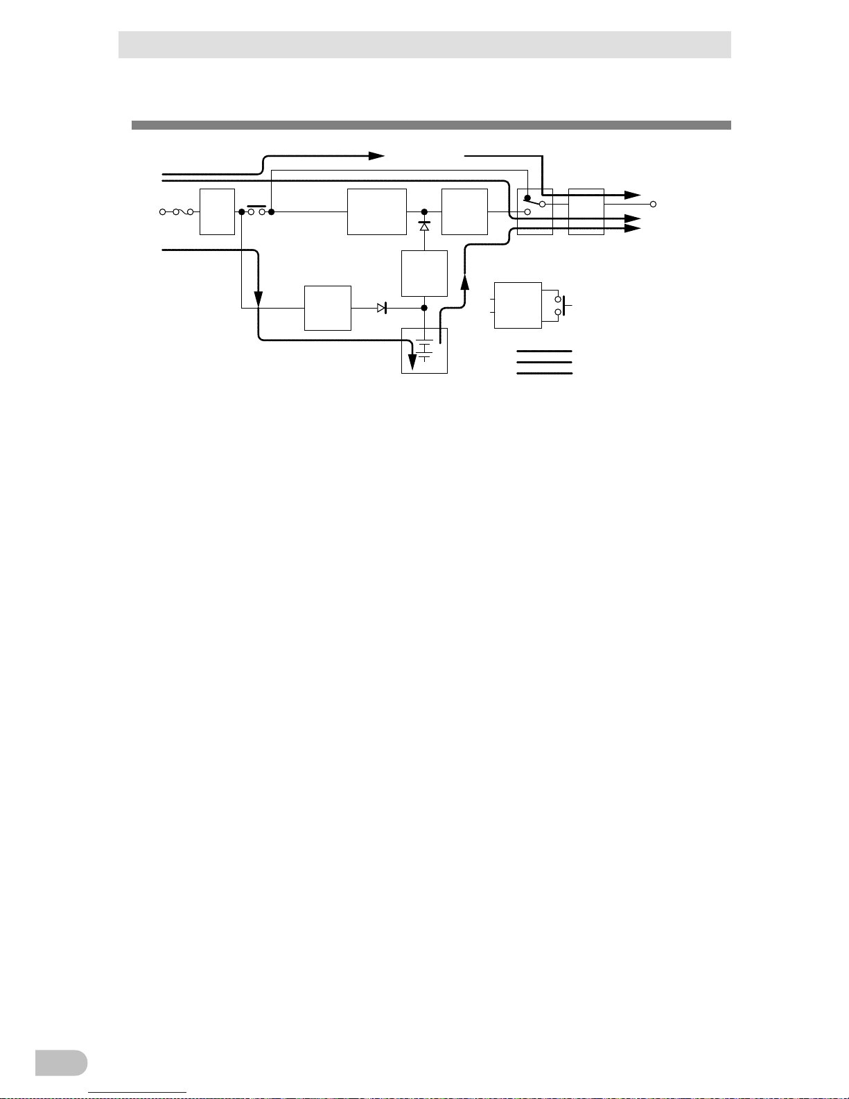
1-5 Diagram of the Input/output circuit block
1-5 Diagram of the Input/output circuit block
Noise
filter
Input
overcurrent
protection
AC100V
input
Power
supply
relay
Charging
circuit
Rectifier
(high power
factor
converter)
Step-up
converter
Inverter
(sine
wave)
Filter
Commercial
power bypass
output
Output
switching
(4 ms. max.)
Control
circuit
Power supply
switch
Battery
At startup/capacity exceeded/error
During Line mode
During Battery mode
Power
supply
output:
AC 100V
BA75T/BA100T/BA100R
20
2 Installation and connection
2-1 Installation
2 Installation and connection
2-1 Installation
Install the UPS.
For cautions when installing the UPS, refer to “Caution (for installation and connection)”
shown in the "Safety precautions" of the beginning of this manual.
The UPS permits the following installing methods. Choose the one best suited for the
environment.
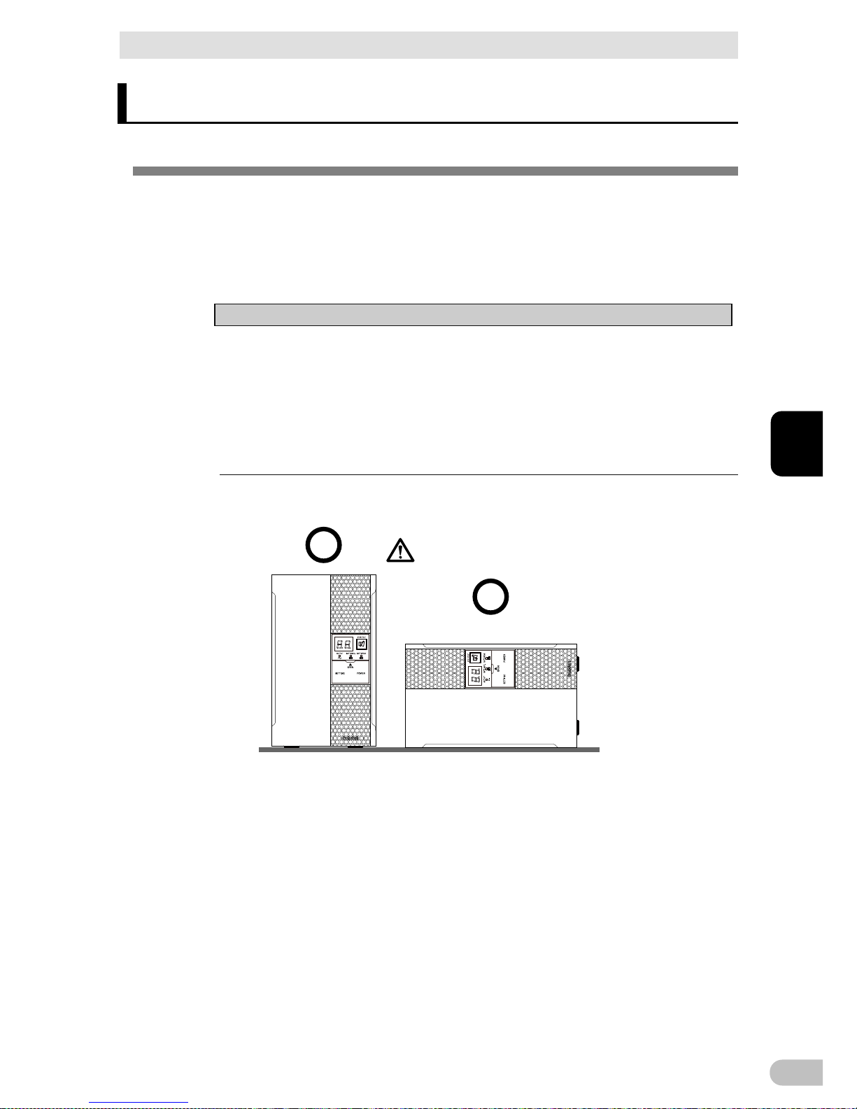
Notes
● Before installing this device, make a record of the serial number of this device.
The product serial number is required when contacting us about the device. The
serial number (S/N) is inscribed on the bottom left side of the rear panel. The
product serial number is inscribed on the bottom left side of the rear panel. The
product serial number label is also included.
●
Allow sufficient space at the back for the AC input cables of the UPS unit and
connected devices.
<BA75T/BA100T>
(Air vents are facing upward)
Ba careful not to get your fingers
caught when arranging the unit.
Correct Positions
BA75T/BA100T/BA100R
21
2
2 Installation and connection
2-1 Installation
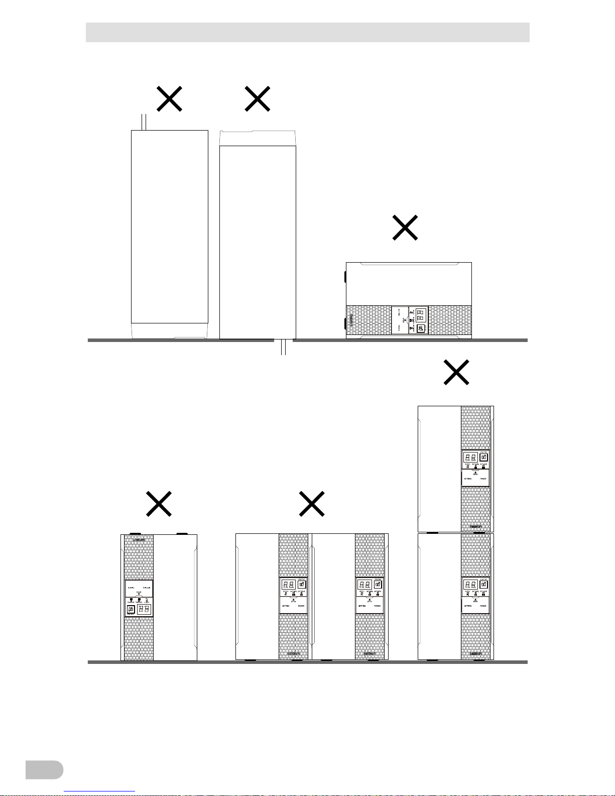
Incorrect Positions
BA75T/BA100T/BA100R
22
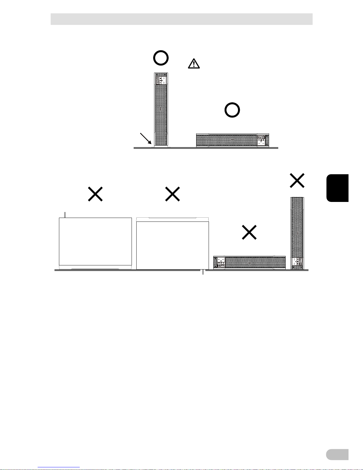
2 Installation and connection
2-1 Installation
<BA100R>
(Air vents are facing upward)
Ba careful not to get your fingers
caught when arranging the unit.
Correct Positions
Note: Upright stand for BA100R,
BAP100R, is necessary for
this position.
Incorrect Positions
BA75T/BA100T/BA100R
23
2
2 Installation and connection
2-1 Installation
2-1-1 Rackmount installation (EIA/JIS 19-inch rack/server
rack)
Caution
When performing rack installation, ensure that the UPS is supported and
stabilized by using both the support angles and the table clamps that
were rated.
● When installing on a rack, make sure that the UPS is supported by the each unit
individually.
● When installing on a rack, make sure to use the support angles and table clamps
included with the product. Without the support angles, the front clamp alone cannot
support the weight of the UPS.
●
The mass of each unit: BA100R: Approx. 13 kg.
In a case where the UPS is to be mounted on a rack, place it on the lower
part of the rack.
● Dropping it may result in injury.
Be sure to use the supplied mounting screws.
● Use of long screws other
than those supplied for case mounting may damage
inside the unit.
● When installing on a rack, make sure to use the support angles and table clamps
included with the product. Without the support angles, the front clamp alone cannot
support the weight of the UPS.
●
Screws other than those supplied may not be strong enough to support the UPS,
causing it to fall.
■
Items included in the 19-inch rack support angle mounting bracket set (BAP100RS)
Rack rail (front) L ................................................................. 1
Rack rail (front) R ................................................................ 1
Rack rail (rear)..................................................................... 2
Ear brackets ........................................................................ 2
Rail length fixing screws (M4 x 8) ........................................ 4
Ear bracket mounting flat-head screws (M3 x 6) ................. 8
EIA/JIS rack fixing screws (M5 x 16) ................................... 10
JIS rack fixing flat-head screws (M5 x 14) ........................... 2
EIA rack fixing nuts (M5) ..................................................... 10
BA75T/BA100T/BA100R
24
2 Installation and connection
2-1 Installation
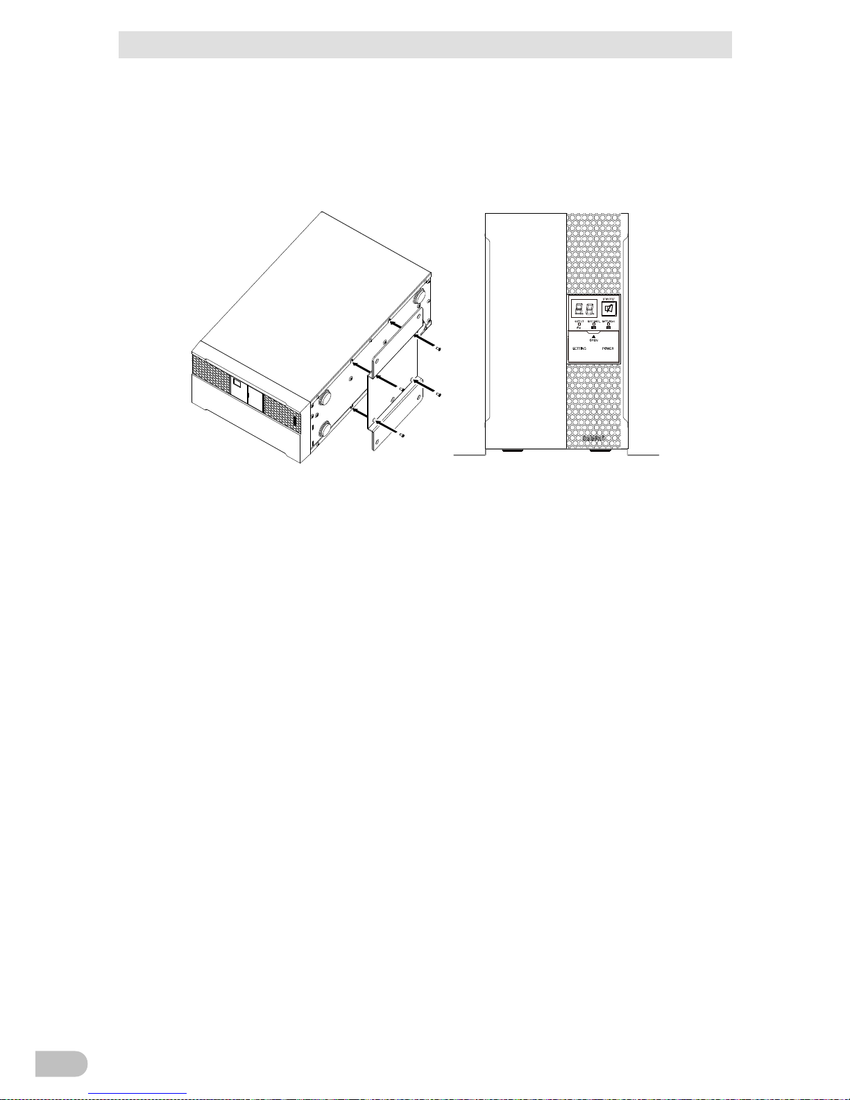
■ Rack mounting procedure
1. Insert the 4 included rail length fixing screws (M4) and half-tighten them to hold the
front and rear rack rails in place. (1 There are 2 types of the front rack rail; left (L) and
right (R). The rear rack rails are same.
4 rail length fixing screws (small)
1
1
2. Adjust the length of support angles to suit the server rack, and then securely tighten the
screws that were half-tightened in step 1. (2
3. For EIA standard-compliant installation, use the 8 included EIA rack fixing nuts (M5)
and 8 EIA/JIS rack fixing screws (M5) to securely fasten the front (the side displaying
“L” or “R”) and the back of the support angles to the server rack. (3 The screw holes
are located at the top and bottom for both front and rear.
For JIS standards, use a total of 6 included screws to fix the rack; 1 JIS rack fixing
flat-head screw (M5) at a front position of the each of right and left support angles, 2
EIA/JIS rack fixing screws (M5) at 2 rear positions. (3 The screw hole position for the
front is at the second screw hole from the top, the rear is at the second screw hole from
the bottom.
2
2
Adjust the length to
suit the server rack
and tighten securely
3
3
Rack fixing screws
BA75T/BA100T/BA100R
25
2
2 Installation and connection
2-1 Installation
4. Use the 8 included ear bracket mounting flat-head screws (2 sets of 4 screws) to
securely fasten the ear brackets to the left and right sides of the UPS. (4
4
4
* The support angles cannot be attached to special EIA/JIS racks.
5. Place the UPS on the support angles and push it completely into the rack (5, and use
the 2 included EIA/JIS rack fixing screws (M5) to securely fasten the ear brackets to the
server rack. (6
5
Push completely in
6
Use the unit fixing
screws to fasten
* Be sure to use the support angles.
BA75T/BA100T/BA100R
26
2 Installation and connection
2-1 Installation
2-1-2 Stationary installation
Perform installation only as shown in the diagrams below.
■ BA100R
● Horizontal installation
Attach the included rubber feet for horizontal installation and position the unit horizontally.
For stationary horizontal installation, make sure that this product does not slide or fall.
● Upright installation
Use the upright stands (2) and M3 flat-head screws (6) included with the rated product.
BA75T/BA100T/BA100R
27
2
2 Installation and connection
2-1 Installation
■ BA75T/BA100T
● Upright installation
Use the upright stands (1) and M3 flat-head screws (4) included with the rated product,
when you want to fix it.
BA75T/BA100T/BA100R
28
2 Installation and connection
2-2 Connecting the equipment
2-2 Connecting the equipment
Caution
(for connection)
Do not connect devices, rated voltage is not 100-120VAC.
● The rated output voltage of this device is 100-120VAC .
● Overcurrent may damage the connected devices.
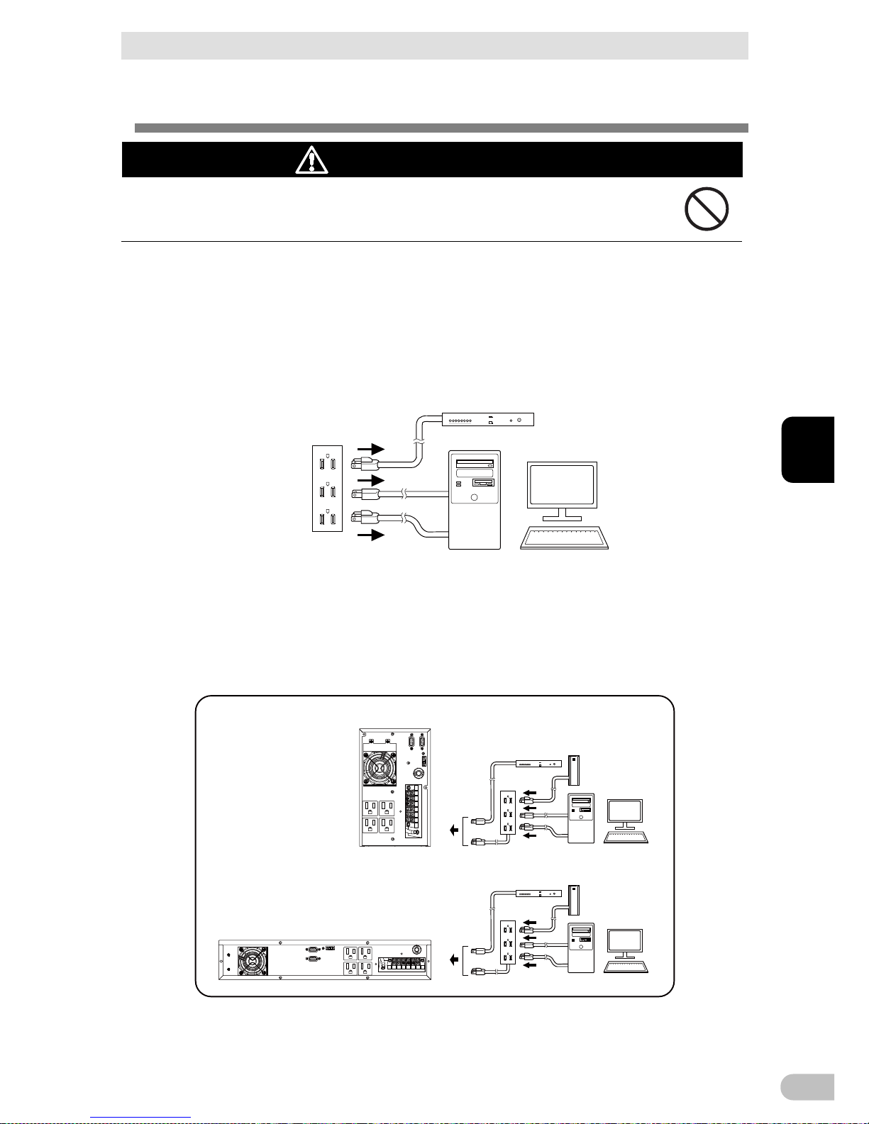
2-2-1 Connecting a device to the power supply output
For cautions when connecting the UPS, refer to “Caution (for installation and connection)”
shown in the “Safety precautions” of the beginning of this manual.
1. Disconnect the AC Input Plugs of all devices you want to back up such as your PC and
modems from a wall outlet (commercial power source).
Wall outlet
(commercial power source)
Computer peripheral devices
PC
2. Connect devices you want to back up to the Power Supply Output Receptacles of the
UPS.
・ If you need more output receptacles than those of the UPS, purchase a plug strip and
use it for extra output receptacles.
BA75T/BA100T
BA100R
Computer peripheral devices
External HDD
Computer peripheral devices
External HDD
BA75T/BA100T/BA100R
29
2
 Loading...