


Ultra-small-sized Tactile Switch with
High Contact Reliability:
1.2 × 3 × 2.5 mm (H × W × D)
■ Industry’s smallest switch* allows high-density
mounting on PCBs for mobile equipment.
*As of October 2006 (according to OMRON survey).
■ Dust-proof constr uction provi des high reli ability in
dusty environments.
■ Surface mounted: Ideal for high-density mounting.
■ Models with ground terminals are available for
protection against static electricity.
RoHS Compliant
(See page 3 for details.)
B3U Ultra-small Tactile Switch
Ordering Information
Packaging Embossed taping
Operation
type
Topactuated
Sideactuated
Order
unit
3,500
pieces
4,000
pieces
Ground
terminal
Without
boss
With boss B3U-1000P-B B3U-1100P-B
Without
boss
With boss B3U-3000P-B B3U-3100P-B
Without ground
terminal
B3U-1000P B3U-1100P
B3U-3000P B3U-3100P
With ground
terminal
Note: Orders must be made in multiples of the order unit speci-
fied above.
Operating Characteristics
Operation type Top-actuated
Item
Operating force (OF) 1.50
Releasing force (RF) 0.2 N min.
Pretravel (PT) 0.15 mm 0.2 mm
(B3U-1000 Series)
± 0.49 N 1.59 ± 0.49 N
+0.2
−0.1
Side-actuated
(B3U-3000 Series)
+0.2
−0.1
Specifications
■ Ratings/Characteristics
Operation
Item
Switching
capacity
Ambient oper ating
temperature
Ambient humidity 35% to 85% (at 5 to 35
Contact
configuration
Contact
resistance
Insulation
resistance
Dielectric strength 250 VAC, 50/60 Hz for 1 min
Bounce time 5 ms max.
Vibration
resistance
Shock resistance
Life expectancy 200,000 operations min. 100,000 operations min.
Maximum
operating force
Weight Approx. 0.022 g
type
Top-actuated
(B3U-1000 Series)
1 to 50 mA, 5 to 12 VDC (resistive load)
−25 to 70°C, 60% humidity (with no icing or conden-
sation)
SPST-NO
100 mΩ max. (initial value) (rated: 1 mA, 5 VDC)
Ω min. (at 100 VDC)
100 M
10 to 55 Hz, 1.5 mm double amplitude
2
1,000 m/s
30 N max.
max.
Side-actuated
(B3U-3000 Series)
°C)
Dimensions
Note: All dimensions are in millimeters unless otherwise indicated. Unless otherwise specified, a tolerance of ±0.2 mm applies to all di-
mensions.
■
Top-actuated Models
Without Ground Terminal, without Boss With Ground Terminal, without Boss
B3U-1000P
2.5 1.4
PCB Mounting
1.7±
0.1
(Top View)
0.1
4.2±
0.1
2.6±
+0.15
1.6
4
3
1.5 dia.
−0.10
+0.15
1.2
−0.10
B3U-1100P
2.5 1.4
1.5 dia.
+0.15
1.6
4
3
0.5
−0.10
+0.15
1.2
−0.10
1.7±
1.9
PCB Mounting
(Top View)
0.1
4.2±
0.1
2.6±
0.1
0.1
0.8±
1.1±
1.1±
0.1
0.1
1
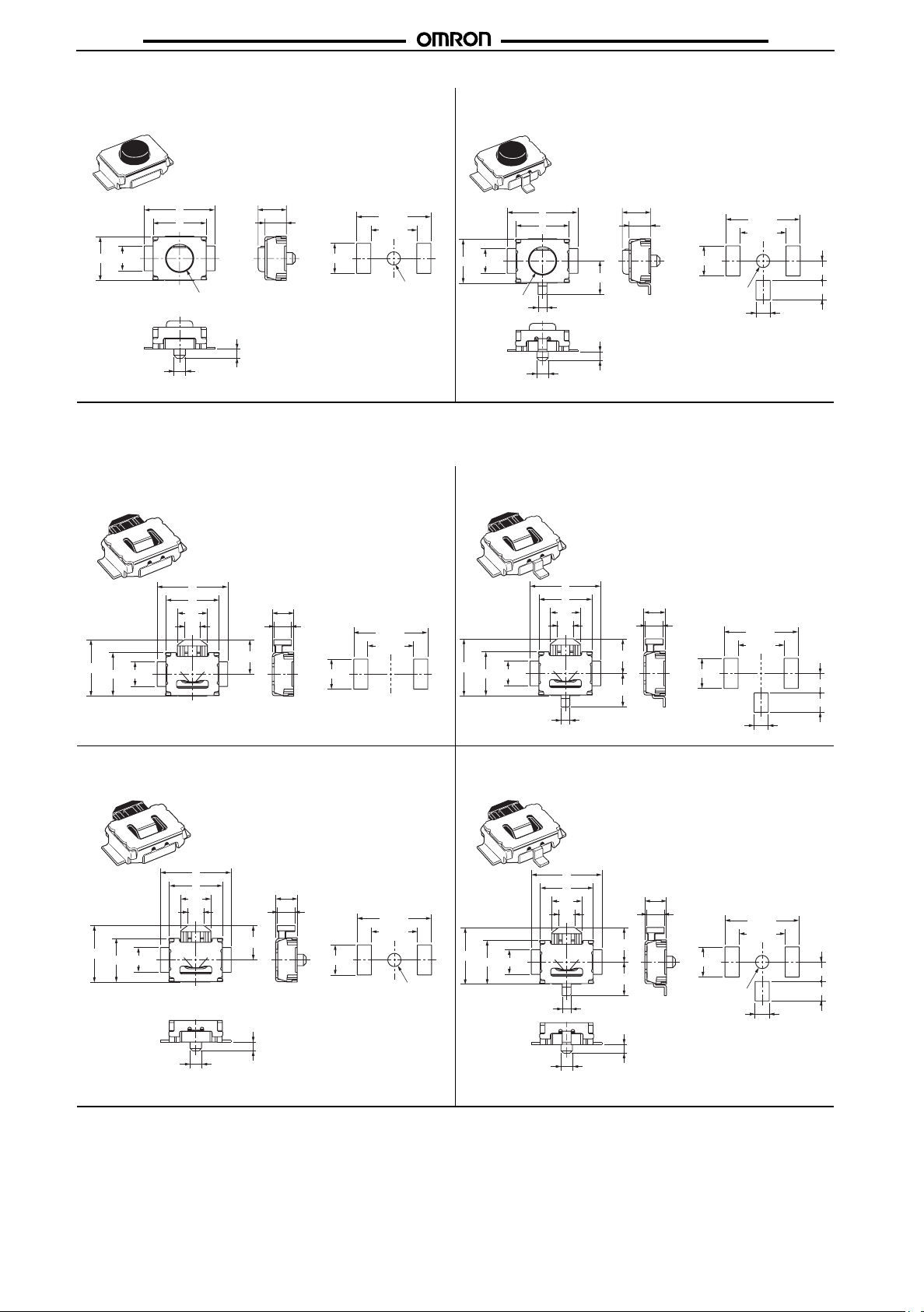
Without Ground Terminal, with Boss With Ground Terminal, with Boss
B3U-1000P-B
B3U-1100P-B
B3UB3U
PCB Mounting
2.5 1.4
0.65±
4
3
0.05 dia.
1.5 dia.
+0.15
1.6
−0.10
+0.15
1.2
−0.10
0.5
1.7±
(Top View)
0.1
0.1
4.2±
0.1
2.6±
Hole: 0.75
+0.15
1.6
4
3
2.5 1.4
+0.1
dia.
0
1.5 dia.
0.5
−0.10
+0.15
1.2
−0.10
1.7±
1.9
Hole: 0.75
0.5
0.05
dia.
0.65±
■ Side-actuated Models
Note: Unless otherwise specified, a tolerance of ±0.2 mm applies to all dimensions.
Without Ground Terminal, without Boss With Ground Terminal, without Boss
B3U-3000P
3.2
2.5 1.4
±0.1
1
±0.1
1.7
PCB Mounting
(Top View)
±0.1
4.2
±0.1
2.6
4
3
1.7
+0.15
1.2
−0.10
0.9
1.95
B3U-3100P
3.2
2.5 1.4
4
3
1.7
0.9
+0.15
1.2
−0.10
0.1
±
1
1.95
±0.1
1.7
1.9
0.5
PCB Mounting
(Top View)
0.1
4.2±
0.1
2.6±
0.1
+0.1
dia.
0
0.1
0.8±
PCB Mounting
(Top View)
0.1
±
4.2
0.1
±
2.6
±0.1
0.8
1.1±
1.1±
1.1
1.1
0.1
0.1
±0.1
±0.1
Without Ground Terminal, with Boss With Ground Terminal, with Boss
B3U-3000P-B
3.2
2.5 1.4
0.65
4
3
1.7
0.9
±
0.05 dia.
1.95
+0.15
1.2
−0.10
PCB Mounting
±0.1
1
±0.1
1.7
(Top View)
±0.1
4.2
±0.1
2.6
Hole: 0.75
+0.1
0.5
dia.
0
B3U-3100P-B
3.2
2.5 1.4
0.65
4
3
1.7
0.9
±
0.05 dia.
+0.15
1.2
−0.10
±
0.1
1
1.95
1.7
1.9
Hole: 0.75
0.5
0.5
PCB Mounting
(Top View)
±
0.1
4.2
±
0.1
2.6
±
0.1
+0.1
dia.
0
±
0.1
0.8
±
0.1
1.1
±
0.1
1.1
2

Precautions
Note: Refer to Safety Precautions in the Tactile Switches (Cat. No. X037) for details on general safety precautions.
Precautions for Correct Use
■
B3UB3U
Soldering
Perform reflow soldering within the ranges shown in the terminal
temperature profile in the following diagram.
C)
°
Temperature (
260 max.
220
180
150
Preheating time
60 to 120 60 max.
Heating
time
Time (s)
Washing
B3U Switches cannot be washed. Doing so will cause the washing agent, together with flux or dust particles on the PCB, to enter
the Switch, resulting in malfunction.
Compliance with RoHS Directive
The “RoHS Compliant” designation indicates that the product
does not contain the following six hazardous substances covered
by the RoHS Directive.
Reference: The following standards are used to determine compliance for the six substances.
Lead: 1,000 ppm max.
Mercury: 1,000 ppm max.
Cadmium: 100 ppm max.
Hexavalent chromium:1,000 ppm max.
PBB: 1,000 ppm max.
PBDE: 1,000 ppm max.
Storage and Operating Environment
Do not store the product under the following conditions to prevent
discoloration and other deterioration of the terminals.
1. Locations subject to high temperatures or humidity
2. Locations containing corrosive gases
3. Locations subject to direct sunlight
The Switch is not provided with a watertight or drip-proof construction. Do not install or operate the product in locations subject
to water spray or splashes.
Packaging Specifications
The specifications for B3U Switches packaged on embossed tape
are as follows:
B3U-1000 Series
0.1
8+
2
0.1
4+
Tape drawing direction
1.75±
2.55
0.1
5.5
0.3
12±
Reel
(19)
330±
13 dia.
2 dia.
Tape drawing
direction
Label
+0.1
1.5 dia.
0
B3U-3000 Series
0.1
8+
2
0.1
4+
1.75±
2.2
0.1
5.5
0.3
12±
Reel
(19)
13 dia.
330±
2
dia.
Tape drawing
direction
Label
+0.1
1.5 dia.
0
Tape drawing direction
Standards Conforms to JEITA.
Package 3,500 Switches (B3U-1000 Series)
4,000 Switches (B3U-3000 Series)
Heat resistance 50
°C for 24 hours (without deformation)
Operation
Do not repeatedly operate the Switch with excessive force. Applying excessive pressure or applying additional force after the
plunger has stopped may deform the disc spring of the Switch,
resulting in malfunction.
Be sure to set up the Switch so that the plunger will be pressed
straight in. The life of the Switch may be reduced if the plunger is
pressed off-center or from an angle. Do not apply pressure from
above or below the plunger. Doing so may deform or damage
parts or cause faulty operation.
Do not operate the plunger from the side. Doing so may deform or
damage the Switch.
3

B3UB3U
ALL DIMENSIONS SHOWN ARE IN MILLIMETERS.
To convert millimeters into inches, multiply by 0.03937. To convert grams into ounces, multiply by 0.03527.
Cat. No. A162-E1-03
In the interest of product improvement, speci fica tions are sub jec t to c hange witho ut notic e.
OMRON Corporation
Electronic Components Company
Switch Division
Manual Switch Department
Shiokoji Horikawa, Shimogyo-ku,
Kyoto, 600-8530 Japan
Tel: (81)75-344-7096/Fax: (81)75-344-7188
Printed in Japan
1106-3M (1006) (C)
 Loading...