

Page 1
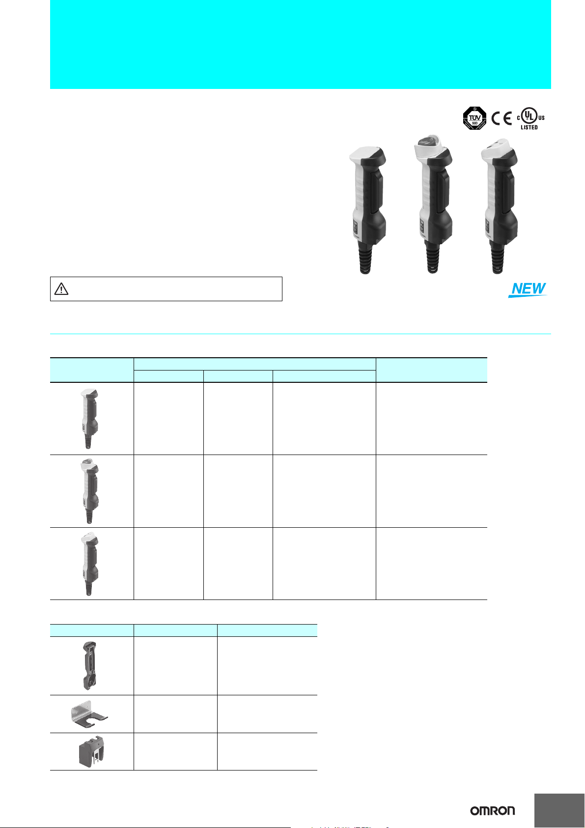
Enabling Grip Switch
A4EG
Enabling Grip Switch with Distinct Feel
for Three Easily Discernible Positions
■ The difficult task of configuring safety circuits is now easily
achieved by combining the A4EG with the G9SX-GS.
■ In addition to the standard models, the lineup also includes
models with an emergency stop switch and models with a
momentary operation switch.
■ An optional Holding Key (sold separately) provides a versatile
method for selecting modes.
■ Equipped with conduit connector.
Be sure to read the “Safety Precautions” on page 12.
Ordering Information
Enabling Grip Switches
Appearance
Enabling switch Monitor switch Pushbutton switch
Two contacts
Two contacts None
Two contacts None
Contact form
1NC
(grip output)
None A4EG-C000041
Emergency stop switch
(2NC)
Momentary operation switch
(2NO)
Model
A4EG-BE2R041
A4EG-BM2B041
Accessories (Order Separately)
Appearance Item Model
Rubber Cover
(replacement part)
Mounting Bracket
(for securing the
A4EG)
Holding Key A4EG-OP3
A4EG-OP1
A4EG-OP2
33
Page 2
A4EG
Specifications
Standards and EC Directives
Compliance with EC Directives and International Standards
• Low Voltage Directive
• GS-ET-22
Certified Standards
Certifying body Standard File No.
TÜV Product Service
UL * UL 508, CSA C22.2 No.14 E76675
CQC (CCC) GB 14048.5 Pending approval
* Certification for CSA C22.2 No. 14 by UL is indicated by the .
EN 60947-5-1
(certified direct opening)
Certified Standard Ratings (Enabling Switch Section)
TÜV (EN 60947-5-1)
Item
Rated operating current (Ie) 0.75 A 0.55 A
Rated operating voltage (Ue) 240 V 125 V
Note: Use a 10-A fuse type gI or gG that conforms to IEC 60269 as the short-circuit protection device.
Utilization category
The fuse is not built into the Switch.
UL/CSA (UL 508, CSA C22.2 No.14), CCC (GB 14048.5)
• 24 VDC, 0.3 A (inductive load)
• 125 VAC, 1 A (resistive load)
AC-15 DC-13
Ask your OMRON
representative.
Ratings
Item
Section
Rated insulation voltage 250 V ---
Rated ON current 2.5 A 5 A 0.1 A
Rated load
Minimum applicable load 24 VDC, 4 mA 5 VDC, 1 mA
Enabling switch
24 VDC, 0.3 A (inductive load)
125 VAC, 1 A (resistive load)
EN certification rating:
AC-15 0.75 A/240 V
DC-13 0.55 A/125 V
General rating:
UL and cUL rating:
Emergency stop switch
(A4EG-BE2R041 only)
125 VAC, 5 A (resistive load)
250 VAC, 3 A (resistive load)
30 VDC, 3 A (resistive load)
125 VAC, 5A
(inductive load, power factor: 0.75 to 0.8)
250 VAC, 3 A
(inductive load, power factor: 0.75 to 0.8)
30 VDC, 3 A (resistive load)
Pushbutton
(A4EG-BM2B041 only)
General rating:
125 VAC, 0.1 A (resistive load)
8 VDC, 0.1 A (resistive load)
14 VDC, 0.1 A (resistive load)
30 VDC, 0.1 A (resistive load)
4
Page 3
Characteristics
Item
Degree of protection IP66 (A4EG-C000041), IP65 (A4EG-BE2R041, A4EG-BM2B041)
Operating section strength Operating direction: 200 N, 1 min
Cable pull strength 30 N, 1 min
Allowable
operating
frequency
Electrical durability
Mechanical durability
Dielectric
strength
Insulation resistance 100 MΩ min. (at 500 VDC)
Vibration
resistance
Shock
resistance
Ambient operating
temperature
Ambient operating humidity 35% to 85%
Ambient storage temperature −25 to 65°C (with no icing or condensation)
Protection against electric
shock
Pollution degree
(operating environment)
Conditional short-circuit
current
Note: The timing of contact outputs for two or more circuits is not synchronized. Confirm performance before application.
Electrical 20 operations/minute max.
Mechanical 20 operations/minute max.
Between
terminals of the
same polarity
Between
terminals of the
different polarity
Between each
terminal and
non-current
carrying
metallic parts
Malfunction 1.5 mm double amplitude, 10 to 55 Hz
Malfunction 150 m/s2 max.
Section
100,000 operations min. (rated load)
OFF-ON-OFF (direct opening):
100,000 operations min.
OFF-ON: 1,000,000 operations min.
2,500 VAC, 50/60 Hz, 1 minute
(impulse voltage)
2,500 VAC, 50/60 Hz, 1 minute
(impulse voltage)
2,500 VAC, 50/60 Hz, 1 minute
(impulse voltage)
−10 to 55°C (with no icing or condensation)
Class II (double insulation)
3 (EN 60947-5-1)
100 A (EN 60947-5-1)
Enabling switch
Emergency stop switch
(A4EG-BE2R041 only)
Operating direction: 367 N, 1 min
Rotating direction: 0.49 N·m, 1 min
10 operations/minute max.
(set/reset for one operation)
10 operations/minute max.
(set/reset for one operation)
100,000 operations min.
(set/reset for one operation)
(rated load)
100,000 operations min.
(set/reset for one operation)
1,000 VAC, 50/60 Hz, 1 minute 1,000 VAC, 50/60 Hz, 1 minute
2,000 VAC, 50/60 Hz, 1 minute 2,000 VAC, 50/60 Hz, 1 minute
2,000 VAC, 50/60 Hz, 1 minute 2,000 VAC, 50/60 Hz, 1 minute
(A4EG-BM2B041 only)
Operating direction: 50 N, 1 min
60 operations/minute max.
120 operations/minute max.
100,000 operations min. (rated load)
2,000,000 operations min.
A4EG
Pushbutton
5
Page 4
A4EG
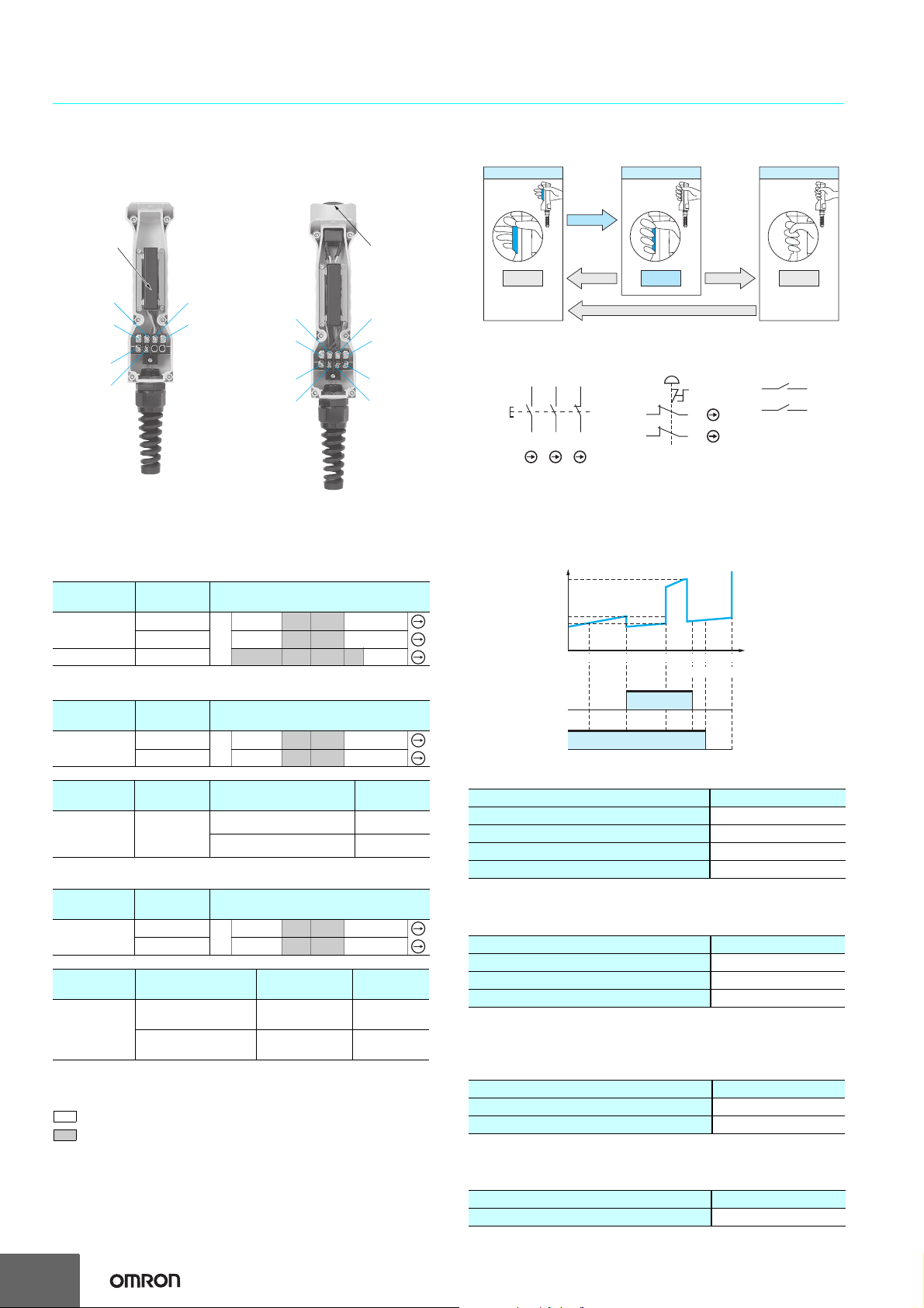
Structure and Nomenclature
Structure
A4EG-C000041
bling Switch
Ena
Section
Terminal 2
Terminal 1
Terminal 5
Terminal 6
Terminal 3
Terminal 4
A4EG-BE2R041
A4EG-BM2B041
Terminal 2
Terminal 1
Terminal 5
Terminal 6
Emergency Stop
Switch Section/
Pushbutton Switch
Section
Terminal 3
Terminal 4
Terminal 8
Terminal 7
Three Positions: OFF - ON - OFF
Position 1
Not Gripped Gripped to
Gripped lightly
OFF
Released
Middle
Position
ON
Released
Gripped Farther
Gripped past
Middle
Position
Contact Configuration
Enabling Switch Emergency Stop Switch Pushbutton Switch
Terminal No.
(2) (4) (6)
Terminal No.
(1) (3)
* Terminal No. (5), (6): A4EG-C000041 only
*
Terminal No.
(5)
(7)
*
(5)
Terminal No.
(6)
(8)
Terminal No.
(5)
(7)
Terminal No. Terminal No.
Position 3Position 2
OFF
(6)
(8)
Contact Forms
Operating Patterns
A4EG-C000041
Operation Terminal No.
Enable output
1 to 2
3 to 4
Position 1
▼
Grip output 5 to 6
A4EG-BE2R041
Operation Terminal No.
Enable output
Pushbutton
switch
Emergency
stop switch
output
1 to 2
3 to 4
Terminal No. Operation Contact
5 to 6
7 to 8
Position 1
▼
Operation (push) ON → OFF
Reset (turn reset) OFF → ON
A4EG-BM2B041
5 to 6
7 to 8
Position 1
▼
Operation Terminal No.
Enable output
Pushbutton
switch
Pushbutton
switch output
1 to 2
3 to 4
Terminal No. Operation Contact
(pushbutton switch A) *
(pushbutton switch B) *
* Refer to Dimensions on page 7 for information on the positions of
pushbutton switches A and B.
OPEN ON: CLOSED
CLOSED OFF: OPEN
Note: 1. The contact ON/OFF timing is not synchronized. Confirm
performance before application.
2. Direct opening only during grip.
Position 2
▼
Position 2
▼
Position 2
▼
Position 3
▼
Position 3
▼
Position 3
▼
Push OFF → ON
Push OFF → ON
Operating Characteristics
Chart (Enabling Switch Section)
OF2
OF1
HF
Operating force
PT1
PT2 TT1 PT3 PT4 TT2
Enable output
(1-2, 3-4)
Grip output
(5-6)
Operating Stroke (Enabling Switch Section)
Operating characteristics Specified value
Enable output (ON) PT2 max. 3.6 mm
Max. enable holding position TT1 Approx. 4.2 mm
Enable direct opening position PT3 max. 6.0 mm
Max. stroke TT2 Approx. 6.7 mm
Operating Force (Enabling Switch Section:
Reference Values)
Operating characteristics Specified value
Enable operating force OF1 max. 14 N
Enable holding force HF * Approx. 8 N
Grip operating force OF2 max. 40 N
* HF: Holding force
Operating Force (Emergency Stop Switch
Section: Reference Values)
Operating characteristics Specified value
Operating force OF max. 14.7 N
Reset force RF max. 0.1 N·m
Operating Force (Pushbutton Switch Section:
Reference Value)
Operating characteristics Specified value
Operating force OF max. 3 N
Operating stroke
6
Page 5

A4EG
Dimensions (Unit: mm)
Enabling Grip Switches
A4EG-C000041
Holding Key Mounted
Conduit connector
MG20A-P-13B Flexible Super Gland
Manufactured by AVC Corporation of Japan (included)
A4EG-BE2R041
60
(50)
38
Enabling switch
174
(262)
48
(34)
44
A4EG-OP3 Holding Key
(order separately)
60
(50)
Enabling switch
54.2
76.2
Holding Key Mounted
48
(34)
174
(277)
47.6
102.6
44
D4NS (order separately)
63
(50)
Conduit connector
MG20A-P-13B Flexible Super Gland
Manufactured by AVC Corporation of Japan (included)
38 44
Enabling switch
(191)
174
(279)
Emergency stop switch
48
(34)
A4EG-OP3 Holding Key
(order separately)
63
(50)
76.2
54.2
Emergency stop switch
Enabling switch
(191)
174
(294)
D4NS (order separately)
48
(34)
47.6
102.6
44
7
Page 6

A4EG
A4EG-BM2B041
Pushbutton
switch A
Pushbutton
switch B
48
(34)
44
Conduit connector
MG20A-P-13B Flexible Super Gland
Manufactured by AVC Corporation of Japan (included)
60
(50)
Enabling switch
(189)
174
(277)
38
48
(34)
44
A4EG-OP3 Holding Key
(order separately)
Holding Key Mounted
60
(50)
76.2
54.2
Enabling switch
(189)
174
D4NS (order separately)
48
(34)
(292)
47.6
102.6
44
Accessories (Order Separately)
Rubber Cover (Replacement Part)
A4EG-OP1
Holding Key
A4EG-OP3
Mounting Bracket (for Securing the A4EG)
A4EG-OP2
50
(44)
(88)
Two, 5.3-dia. holes
Enabling Grip Switch Mounted
83.2
43.3
235.9
(82)
t3
Mounting surface
8
Note: The screws are not included.
Page 7

Application Examples
Application Examples
Machining Equipment Maintenance Mode
• Switching between normal operation mode and maintenance mode is performed manually.
• In normal operation mode, the Safety Door Switch is enabled, and in maintenance mode, the Enabling Grip Switch is enabled.
A4EG
Normal Operation Mode
Emergency Stop Switch
Door
1. Emergency
2. Door
1. Emergency
Stop Switch
4. Mode Selector
3. Enabling Grip
Switch
Stop Switch
Emergency
Stop Switch,
e.g., A22E
Basic Unit
G9SX-BC
Logical AND
connection
When pressed, processing will stop.
When the door is opened, processing will stop.
2.
Door
Guard Lock
Safety-door Switch,
e.g., D4NL
Safety Guard
Switching Unit
G9SX-GS
Contactor
Conveyor
3. Enabling Grip
Switch
Enabling
Grip Switch
A4EG
4. Mode
Selector
Key-type
Selector Switch
A22K
Enabling Grip Switch
The Enabling Grip Switch will be disabled.
Maintenance Mode
Emergency Stop Switch
Door
Enabling Grip Switch
When pressed, processing will stop.
The Door Switch will be disabled.
Processing will be possible only when the operator is gripping
the Enabling Grip Switch.
Note: For information on the G9SX-GS, refer to Safety Components Series Catalog (Cat. No. Y106) and G9SX User’s Guide (Cat. No. Z255).
9
Page 8

A4EG
Wiring Example
Settings (For details, refer to section 3 of the G9SX User’s Guide (Cat. No. Z255).)
G9SX-BC: Manual reset, cross fault detection: ON (category 4 wiring)
G9SX-GS: Manual reset, cross fault detection: ON (category 4 wiring), logical AND connection setting: AND
ON-delay time setting: Time is set.
Switching mode: Manual
External indicator diagnosis: Enabled
Wiring Example
Feedback loop
+24 V
GND
11 21
12
S1
T11A1T12 T21 T22 T31 T32 T33
G9SX-BC202
Control circuit
S14A2S24
KM1 KM2
KM1
22
KM2
S2
+24 V
Open
Y1
L1 L2 X1 X2
PLC etc.
Lock release signal
S5
KM3
KM4
KM1
KM2
42
41
121134
S1: Emergency Stop Switch
S2, S7: Reset switches
S3: Enabling Grip Switch
M1
S4: Guard lock Safety-door Switch
S5: Lock release switch
S6: Safety limit switch
KM1 to KM4: Contactors
M1 to M2: 3-phase motors
S4
54
53
33
+24 V
Enabling
Grip Switch
S3
G9SX-GS226-T15
GND
T11A1T12 T21
S14A2S24
KM4KM3
Mode selector
Y1
T22
Control circuit
S54
S44
Door
OPEN
Stop signal
+24 V
OpenOpen
Y3
M1 M2
L1 X3X2X1 X4
PLC etc.
(Diagnostic check enabled)
T61 T62
Indicator
To PLC
To PLC
S6
Open Open
T71
Y2
T72 T31 T32 T33 T41 T42
Y4
Feedback loop
S7
KM3
KM4
+24 V
UA UB
Indicator
(Diagnostic check enabled)
AND
OFF
Manual
Auto
KM3
KM4
M2
Note: For this circuit example, the
category is equivalent to 4.
10
Page 9

Timing Chart
A4EG
G9SX-BC202 (Upper Unit)
Emergency stop switch S1
Reset switch S2
KM1, KM2 NC contact
KM1, KM2 NO contact
Logical AND output L1
G9SX-GS226-T15 (Lower Unit)
Logical AND input T41
Guard lock safety-door switch S4
Enabling grip switch S3
Reset switch S7
Mode selection input M1
Mode selection input M2
KM3, KM4 NC contact
KM5, KM6 NC contact
KM3, KM4 NO contact
KM5, KM6 NO contact
(10)
(8)(3)
(4)
(1)
(2)
(6)
(7)(5) (9)
OFF-delay timeOFF-delay time OFF-delay time OFF-delay time
(1) The lower unit starts in operation mode.
(2) The mode switches to maintenance mode.
(3) The operator opens the door and performs maintenance work.
(4) The Enabling Grip Switch is gripped to the middle position.
(5) The lower unit starts in maintenance mode.
(6) The lower unit will stop when the Enabling Grip Switch is released or gripped.
(7) The lower unit will start again after the door is closed and the mode is switched to operation mode.
(8) The lower unit will stop when the door is open while in operation mode.
(9) The door is closed and the lower unit starts again.
(10) The upper unit and lower unit will stop if the emergency stop is pressed.
11
Page 10

A4EG
Safety Precautions
!WARNING
Always verify the operation of the safety functions before
starting the system. Not doing so may result in the safety
functions not performing as expected if the wiring or
settings are incorrect or the switches have failed.
Do not drop the switch. Doing so may damage the switch
and the system may continue to operate, possibly
causing injury or death.
Precautions for Safe Use
• This product is a switch for teaching the machine such as robot in
hazardous area. The machine is allowed to operate only when
operating the switch continuously. Configure the system so that the
machine can be operated only at position 2.
• Apply load current not to exceed the rated value.
• Do not use the switch submerged in oil or water or in locations
continuously subject to splashes of oil or water. Doing so may
result in oil or water entering the switch.
• Do not use the switch in locations where explosive or flammable
gasses may be present.
• Mount the switch securely to prevent it from falling. Otherwise,
injuries may occur.
• The durability of the switch is greatly influenced by the switching
conditions. Always test the switch under actual conditions before
application and use it in a switching circuit for which there are no
problems with performance.
• Always attach the cover after completing wiring and before using
the switch. Electric shock may occur if the switch is used without
the cover attached.
• The user must not maintain or repair equipment incorporating the
switch. Contact the manufacturer of the equipment for any
maintenance or repairs required.
• Do not disassemble or remodel the switch in any case, or the
switch will not operate normally.
• Do not override by inserting the Holding Key itself in the door
switch.
• Configure the circuit so that the machine does not operate when
operating the Enabling Switch while the Holding Key is being
inserted in the door switch.
• Do not impose excessive vibration or shock on the Door Switch
while the Holding Key is inserted. Excessive vibration or shock
may cause the Switch to fail or break.
• Do not incline and pull the switch body or do not impose shock on
the switch body in the directions shown with the arrows in Fig.1.
Otherwise, the switch may be damaged and may not operate
properly.
• Refer to the D4NS Safety-door Switch Datasheet and Instruction
Sheet about the storage, ambient conditions, the details and
handling of the Switch.
Fig. 1
No operation No operation
Insertion-pull direction
(Perpendicular direction)
No operation
A4EG
Top position
No operation
Arrow indicates
insertion-pull direction.
Precautions for Correct Use
• Do not hold the Enabling Switch Device at Position 2 by any other
methods except for handling. Otherwise, the original function of the
Enabling Switch Device is not worked.
Operating Environment
• This switch is designed for use indoors. Using the switch outdoors
may damage it.
• The switch contacts can be used with either standard loads or
microloads. Once the contact be used to switch smaller loads. The
contact surfaces will become rough once they have been used and
contact reliability for smaller loads may be reduced.
• Do not use the switch in the following locations.
• Locations where the interior of the Protective Door may into
direct contact with cutting chips, metal filings, oil chemicals
• Locations subject to detergents, thinners, or other solvents
• Locations subject to sudden temperature changes
• Locations subject to high humidity and condensation
• Locations subject to severe vibration
• Do not use the switch where corrosive gasses (e.g.,H
NH
3,HNO3, or Cl2) are present or in locations subject to high
2S, SO2,
temperature and humidity. Doing so may result in damage to the
switch as a result of contact failure or corrosion.
• Do not store the switch where corrosive gasses (e.g.,H
NH
3,HNO3, or Cl2) or dust are present or in high temperature and
2S, SO2,
humidity.
• If the switch is not turned ON and OFF for a long period of time,
contact resistance may be increased or continuity failure may
occur due to contact oxidation.
Mounting Method
Specified Tightening Torque
Loose screws may result in malfunction. Tighten the screws at the
specified torques.
Item Specified torque
Cover mounting screw 1.1 to 1.3 N·m
Terminal screw 0.4 to 0.5 N·m
Holding Key mounting screw 0.5 to 0.7 N·m
Conduit Connector mounting
(Conforming spanner 27 mm
(width across flats))
Mounting Bracket 2.4 to 2.8 N·m
Cover Mounting
• Dislocation of the seal rubber or foreign substance on the seal
rubber reduces seal performance of the switch. Mount the cover
after confirming that there is no abnormality on the seal rubber. If
the seal rubber cracks or breaks, replace the Cover with a new one
(A4EG-OP1 Rubber Cover, separately sold).
• Do not touch the rubber boot with sharp objects. Otherwise, the
rubber boot may break and the operating characteristics and the
seal performance may not be satisfied.
Seal Cover, A4EG-OP1 (sold separately)
2.0 to 2.4 N·m
12
Holding Key
A4EG-OP3
(sold separately)
D4NS (sold separately)
Magnified View
Mounting surface
Rubber boot
Seal rubber
Installing Mounting Bracket
• Securely install the Mounting Bracket using M5 screws and
washers and tighten them to a torque of 2.4 to 2.8 N·m.
Page 11

A4EG
Holding Key Type (sold separately)
• Use the A4EG-OP3 Holding Key when using the A4EG combining
with the door switch.
• Use the D4NS Safety-door Switch.
• Loose screws may result in malfunction. Tighten the screws at the
specified torques. Adhesive is recommended to prevent screws
from being loose.
The specified torque: 0.5 to 0.7 N·m (Mounting screw, 2pcs.)
• Do not impose excessive force on the tip of the Holding Key or do
not drop the switch body when the Holding Key is mounted on the
switch body. Otherwise the Holding Key may deform or break. Stop
using in case that deformation or breakage of the Holding Key
occurs.
• Use the provide Spring washers and Mounting screws when
mounting the Holding Key. Fit a tip of a slotted-screw driver on the
head of the Mounting screw as shown in the following figure when
tightening Mounting screws. The Mounting screws cannot be
released once tightened.
Holding Key
A4EG
• As shown in figure 1 in Precautions for Safe Use, install the D4NS
so that its mounting surface is above the highest part of the A4EG.
• As shown in figure 1 in the Precautions for Safe Use, use the
Holding Key inserted vertically to the insert hole.
A4EG-OP3 (sold separately)
Spring washer, 2 pcs.
(provided)
Mounting screw, 2 pcs.
(provided)
• Do not pull the cable when the Enabling
Switch Device is hung on the Bracket.
Bracket
A4EG-OP2
(sold separately)
• Use crimp terminals with insulator tube for wiring.
Recommended crimp terminal (Ring tongue terminal, Nylon-
insulated): J.S.T. Mfg Co. FN1.25-3.7 (F Type)/
N1.25-3.7 (Straight Type)
t: 0.8 mm
dz dia.: 3.7 mm
D dia.4.0 mm
B: 5.5 mm
L: 15.7 mm
F: 4.0 mm
I: 9.0 mm
D dia.
L
l F
B
dz dia.
• Cut and crimp the lead wires in length as shown in the following
table.
Otherwise, excess length may cause the cover to rise and not fit
properly.
Terminal ArrangementLead Wire Lengths
Terminal 2
Terminal 1
Terminal 3
Terminal 4
Using the A4EG-BE2R041 (Enabling Grip Switch
Equipped with an Emergency Stop Button)
If the A4EG is installed in a machine, do not use the A4EG alone as
an emergency stop switch or as an emergency shutoff switch as
specified by SEMI-S2.
SEMI-S2 specifies the installation of emergency shutoff switches at
specified intervals on equipment. The A4EG can be removed from the
equipment, and so may not satisfy the requirements of SEMI. Use the
A4EG in combination with emergency stop switches or emergency
shutoff switches that are installed at fixed positions.
Wiring
• Confirm that safety is satisfied on the operation of the equipment
to wire.
• Do not put the electric power when wiring. Otherwise electric shock
may occur.
• Use an adequate diameter of cable. The seal performance is
reduced when the diameter is smaller than the adequate diameter.
• Use the conforming sizes of lead wires to the apply voltage and
current.
Conforming cable size
Recommended multi-wire cable size: AWG20 to 18
(0.5 to 0.75 mm
Recommended cable diameter: 8.0 to 13 mm
(used with provided Conduit
Connector)
• Do not pull the lead wires with excessive force. Doing so may
disconnect them.
2
)
L2
L1
Terminal 5 Terminal 6 Terminal 7 Terminal
8
Length of lead wires Terminal No. 1-4 5-8
L1/L2
(Length to the centers of crimp terminals)
40±2 mm 25±2 mm
• Do not let particles such as small piece of lead wire in the switch
body when wiring.
Terminal No. and Circuit Configuration
Model Circuit Terminal No.
A4EG-C000041
A4EG-BE2R041
A4EG-BM2B041
• Assemble all of the parts without leaving any parts as shown in the
following figure when mounting Conduit Connector.
Mount Rubber packing, Conduit part, Cable Seal part and Spiral
Nut part in order.
Enable output 1-2, 3-4
Grip output 5-6
Enable output 1-2, 3-4
Emergency Stop
Pushbutton Switch output
5-6, 7-8
Enable output 1-2, 3-4
Pushbutton Switch output 5-6, 7-8
Rubber packing
Cable seal part
Spiral nut part
Conduit part
• Both of the switches is ON when pushing the two push buttons
simultaneously. Confirm that safety is satisfied on the operation of
the equipment to wire. (A4EG-BM2B041)
• Perform maintenance inspections periodically.
13
Page 12

OMRON Corporation
Industrial Automation Company
Safety Devices Division
Shiokoji Horikawa, Shimogyo-ku,
Kyoto, 600-8530 Japan
Tel: (81) 75-344-7093/Fax: (81) 75-344-8197
Regional Headquarters
OMRON EUROPE B.V.
Wegalaan 67-69, NL-2132 JD Hoofddorp
The Netherlands
Tel: (31)2356-81-300/Fax: (31)2356-81-388
OMRON SCIENTIFIC TECHNOLOGIES INC.
6550 Dumbarton Circle, Fremont
CA 94555-3605 U.S.A.
Tel: (1) 510-608-3400/Fax: (1) 510-744-1442
OMRON ASIA PACIFIC PTE. LTD.
No. 438A Alexandra Road # 05-05/08 (Lobby 2),
Alexandra Technopark, Singapore 119967
Tel: (65) 6835-3011/Fax: (65) 6835-2711
OMRON (CHINA) CO., LTD.
Room 2211, Bank of China Tower,
200 Yin Cheng Zhong Road,
Pu Dong New Area, Shanghai, 200120, China
Tel: (86) 21-5037-2222/Fax: (86) 21-5037-2200
Authorized Distributor:
Note: Specifications subject to change without notice.
Cat. No. C142-E1-01
Printed in Japan
1007-?M (1007) (?)
 Loading...