

Page 1
12
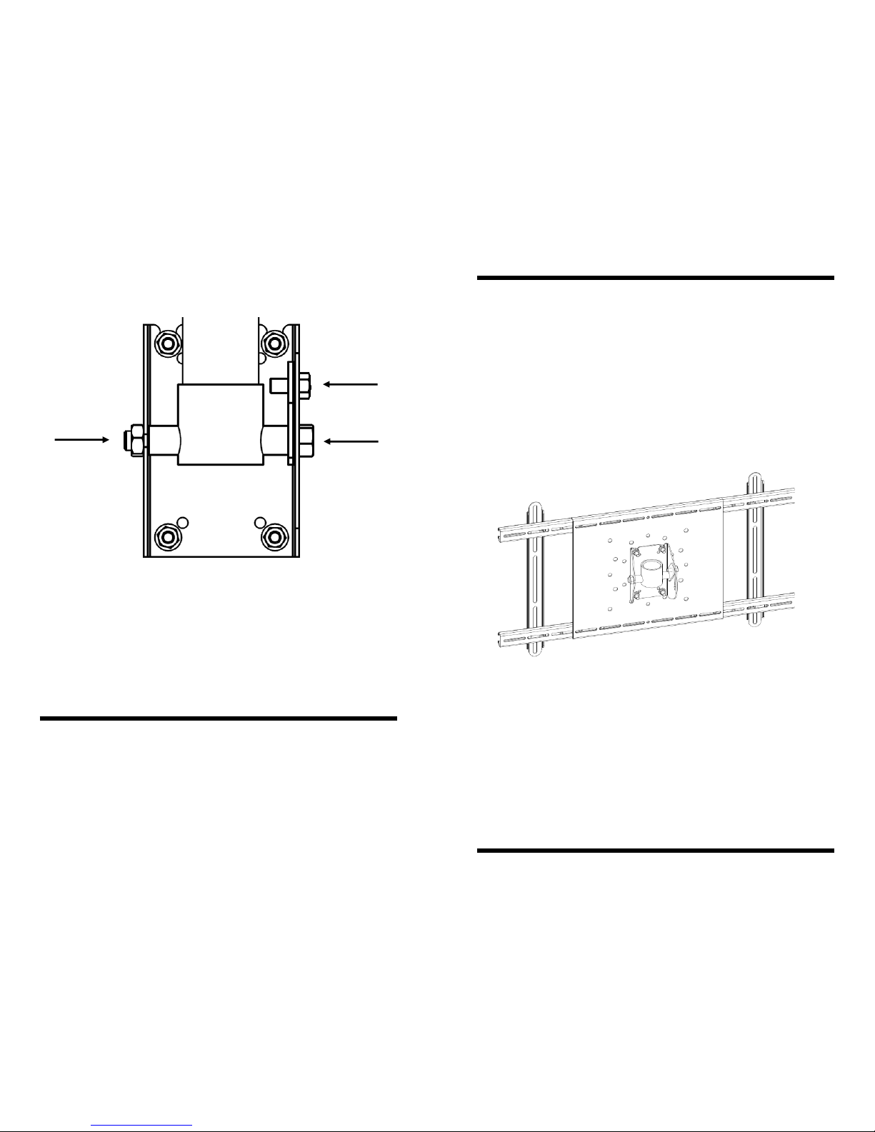
To adjust tilt
1. Hold A with 3/4” Socket
2. Loosen B with 3/4” Socket
3. Loosen C with 9/16” Socket
4. Position Display
5. Tighten A,B, & C
C.
B. A.
Step 10 — Adjusting Tilt
PN —9/05
Specifications are subject to change without prior notice.
Every effort has been made to provide accurate and error-free assembly and installation. OmniMount Systems disclaims liability for any difficulties arising from the interpretation of information
contained in these instructions. If OmniMount products are used for purposes other than their
original intent, OmniMount, its distributors and retailers shall not be held responsible or liable for
injuries or property damage, direct, indirect, or consequential, which may arise from the inability
to use this product safely, properly, and in the manner for which it has been designed and manufactured. Warranty does not apply to products which have been lost, damaged by misuse, abuse, or
accident.
Installation Instructions
TPUM-1: Tilting Pipe Adapter
• Designed for 26” - 55” Flat Panel TV’s
• Maximum Weight Capacity: 175 lbs. (79.4 Kg)
• Connects to 1.5” NPT Pipe
Page 2
2 11
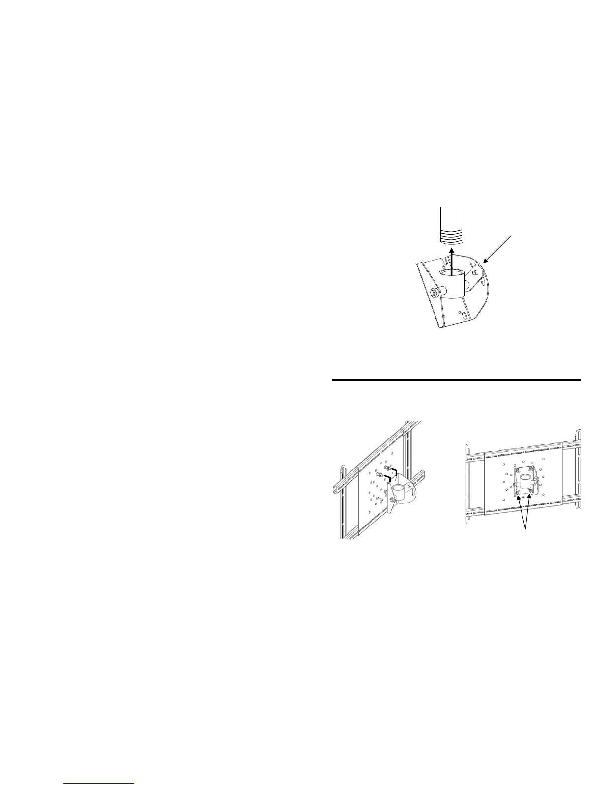
Step 8 — Attaching the Tilt-PA to the Pipe
1. Thread and tighten Tilting Pipe Adapter onto 1.5” NPT Pipe (not included).
2. Tighten Tilt Tension Nut before attaching Adapter.
Tighten Here
Step 9 — Attaching the Adapter and Display to the Pipe Adapter
3. Align the space between the
top Nuts with the grooves in the
Tilting Pipe Adapter and gently
lower the Adapter.
4. Thread the last Nylock Nuts (2)
onto the bottom two Stud Screws.
5. Securely tighten all Nylock Nuts
4.
Note: Pipe removed for clarity
Page 3

10
Step 7 — Attaching the UM1 to the Display
1. Thread Mounting Screw through Square Washer, Rail, Spacer (if needed),
and into the Display’s Mounting Holes.
Mounting
Screw
Display
Spacer
(if needed)
Square
Washer
NOTE: Ensure Retaining Screws are loose enough to allow for adjustment
2. Center the Back Plate on the Display and securely tighten the Retaining
Screws and Mounting Screws
Back
Plate
Important
DO NOT over tighten the mounting screws, or the display may be damaged.
NEVER use a power driver to tighten the mounting screws.
3
Extended Rails
Standard Rails
Back Plate
Channel
Required Tools:
Ratchet and 5/16” Deep Socket
or
5/16” Open Wrench
or
Adjustable Spanner Wrench
Large Universal Adapter Component Guide
Page 4
4
ID Description Qty
A Philips Screws M4 x 16mm 4
B Philips Screws M4 x 36mm 4
C Philips Screws M4 x 45mm 4
D Philips Screws M5 x 16mm 4
E Philips Screws M5 x 36mm 4
F Philips Screws M5 x 46mm 4
G Philips Screws M6 x 16mm 4
H Philips Screws M6 x 36mm 4
I Philips Screws M6 x 46mm 4
J Philips Screws M8 x 16mm 4
K Philips Screws M8 x 36mm 4
L Philips Screws M8 x 46mm 4
M 5/8" Urethane Spacer 4
N 3/4" Urethane Spacer 4
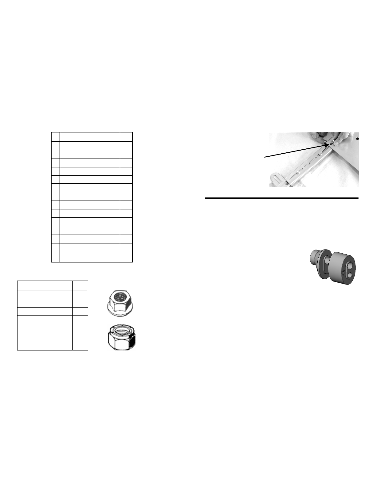
Description Qty
6mm x 12mm Screws 8
Square Washer 4
Small Hex Wrench 1
Stud Screws 4
5/16" Flange Nuts 4
5/16" Nylock Jam Nuts 4
Large Hex Wrench 1
Parts List
Nylock Jam Nut
Flange Nut
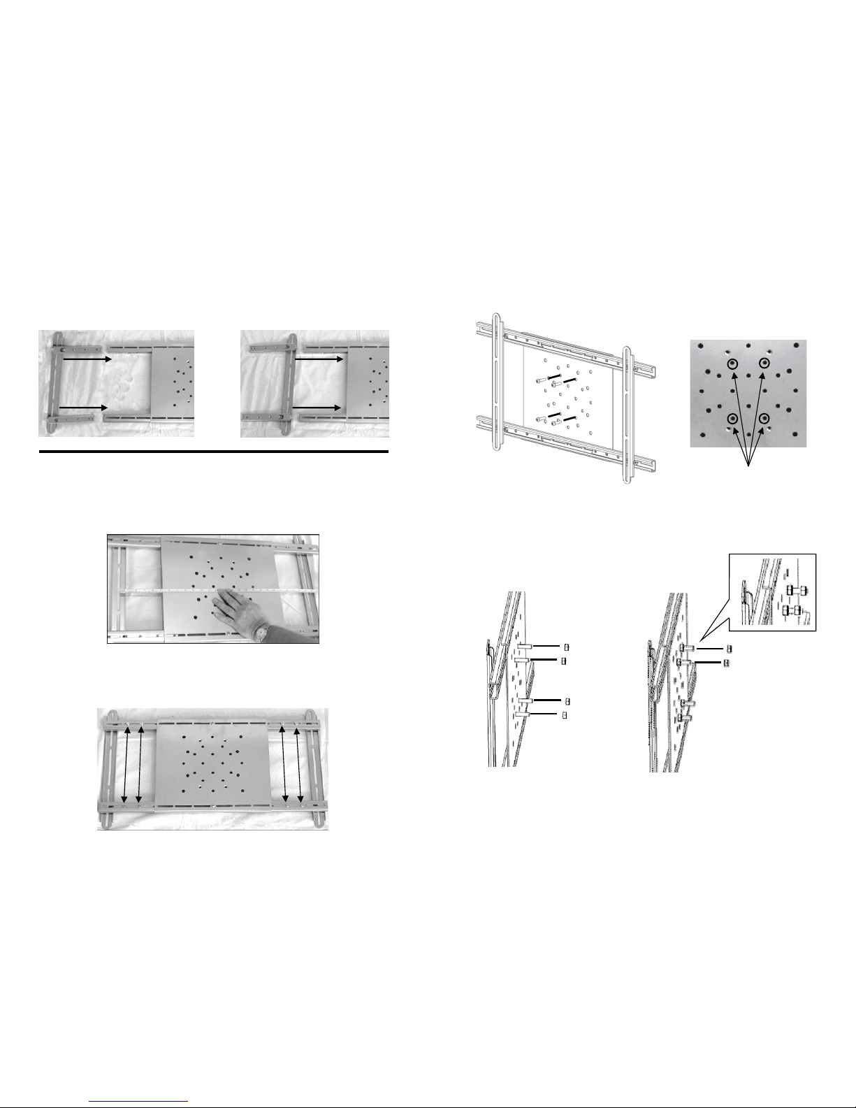
9
NOTE: The outer corners
of the Back Plate must always be secured. Some
wide Displays will require
the installation of a 6mm
Screw and 6mm L ock Nut
(not included) to secure the
Back Plate.
Step 5 — Secure Sliders and Back Plate (continued)
Step 6 — Hardware Selection
Consult the supplied Hardware Cross Reference list, and locate the appropriate
mounting screws (A-L) for your display
Spacers
Some displays will require the use of a spacer.
There are two spacers provided:
5/8” (16 mm) round nose spacer (M)
3/4” (19 mm) block spacer (N)
The spacers may be used individually, or may be snapped together to create
one large stacked spacer. The spacers have been designed to snap directly into
the mounting rail for ease in handling, and also include two different mounting
holes to manage the various screw sizes.
Generally, the 5/8” Spacer (M) is used on displays with slightly curved backs
and/or recessed mounting lands. The 3/4” Spacer (N) is used on displays with
curved backs, and Stacked Spacers (M&N) will be used on displays with
deeply curved backs and/or protruding accessories.
Page 5
8
Step 4 — Rail Installation
Standard Configuration
Narrow Configuration
Step 5 — Secure Sliders and Back Plate
1. Set Rails to horizontal distance between Mounting Holes on Display.
2. Loosely thread Slider Retaining Screws through Channels into Sliders
5
Step 1 — Set Studs in UM-1
1. Insert Stud Screws (4) into front of Adapter.
2. Thread Flange Nuts (4)
onto Stud Screws and tighten
using a 5/16” Socket.
3. Thread Nylock Nut (2) onto the
two top Stud Screws leaving space
between Nylock and Flange Nuts.
Insert Stud
Screws Here
Page 6

6
Step 2 — Determine Rail Selection
Measure the vertical distance between
Mounting Holes on Display.
If distance is greater than 19” (48cm)
use the supplied Extended Rails.
1. Using the Small Hex Wrench
unscrew the Slider Retaining
Screws (8).
3. Using the Small Hex Wrench unscrew the Rail Retaining Screws (4)
and remove the Standard Rail.
Rail
Retaining
Screws
Slider
Rail
Rail Retaining
Screw Holes
2. Pull to remove the Standard
Rail and attached Sliders.
Slider
Retaining
Screws
4. Replace with the Extended Rail,
insert the Rail Retaining Screws and
tighten.
Extended Rail Installation
(only if required)
7
Step 3 — Determine Width Configuration
Measure the horizontal distance between
Mounting Holes on Display.
See below for Width Configuration details.
Standard Configuration
Narrow Configuration
Range: 15 ¾” (40cm) to 38 ½” (98cm)
Range: 3 ½” (9cm) to 15 ½” (39cm)
Prior to adjustment, loosen Slider Retaining Screws.
 Loading...