

Page 1
Page 2

OMEGAnetSM On-Line Service
http://www.omega.com
Servicing North America:
Internet e-mail
info@omega.com
USA:
Canada:
One Omega Drive, Box 4047
Stamford, CT 06907-0047
Tel: (203) 359-1660
e-mail: info@omega.com
976 Berger
Laval (Quebec) H7L 5A1
Tel: (514) 856-6928
e-mail: canada@omega.com
FAX: (203) 359-7700
FAX: (514) 856-6886
For immediate technical or application assistance:
USA and Canada:
Mexico and
Latin America:
Sales Service: 1-800-826-6342 / 1-800-TC-OMEGA
Customer Service: 1-800-622-2378 / 1-800-622-BEST
Engineering Service: 1-800-872-9436 / 1-800-USA-WHEN
TELEX: 996404 EASYLINK: 62968934 CABLE: OMEGA
Tel: (95) 800-TC-OMEGA
En Espanol: (95) 203-359-7803
SM
FAX: (95) 203-359-7807
e-mail: espanol@omega.com
SM
SM
SM
Servicing Europe:
Benelux:
Czech Republic:
France:
Germany/Austria:
United Kingdom:
It is the policy of OMEGA to comply with all worldwide safety and EMC/EMI regulations that
apply. OMEGA is constantly pursuing certification of its products to the European New Approach
Directives. OMEGA will add the CE mark to every appropriate device upon certification.
The information contained in this document is believed to be correct but OMEGA Engineering, Inc. accepts
no liability for any errors it contains, and reserves the right to alter specifications without notice.
WARNING: These products are not designed for use in, and should not be used for, patient connected applications.
Postbus 8034, 1180 LA Amstelveen, The Netherlands
Tel: (31) 20 6418405
Toll Free in Benelux: 06 0993344
e-mail: nl@omega.com
ul. Rude armady 1868
733 01 Karvina-Hranice
Tel: 420 (69) 6311899
e-mail:czech@omega.com
9, rue Denis Papin, 78190 Trappes
Tel: (33) 130-621-400
Toll Free in France: 0800-4-06342
e-mail: france@omega.com
Daimlerstrasse 26, D-75392 Deckenpfronn, Germany
Tel: 49 (07056) 3017
Toll Free in Germany: 0130 11 21 66
e-mail: germany@omega.com
25 Swannington Road,
Broughton Astley, Leicestershire,
LE9 6TU, England
Tel: 44 (1455) 285520
FAX: 44 (1455) 283912
Toll Free in England: 0800-488-488
e-mail: uk@omega.com
FAX: (31) 20 6434643
FAX: 420 (69) 6311114
FAX: (33) 130-699-120
FAX: 49 (07056) 8540
P.O. Box 7, Omega Drive,
Irlam, Manchester,
M44 5EX, England
Tel: 44 (161) 777-6611
FAX: 44 (161) 777-6622
Page 3

Introduction to this Manual
This manual is the Personal488 User’s Manual for Windows 95 and Windows NT.
The material in this manual discusses PC/IEEE 488 controller interface hardware and their
accompanying 32-bit driver software. This material is divided into the following sections:
• Chapter 1: Personal488 Overview gives a general description of both the interface hardware and
the driver software associated with each of the Personal488 PC/IEEE 488 controller interface
packages discussed in this manual.
• Chapter 2: Personal488/PCI (with PCI488) provides a discussion of the hardware specifications,
and the instructions for the installation of the "plug-&-play" PCI488 interface and its drivers.
• Chapter 3: Personal488/ATpnp (with AT488pnp) provides a discussion of the hardware
specifications, and the instructions for the installation of the "plug-&-play" AT488pnp interface
and its drivers.
• Chapter 4: Personal488/CARD (with CARD488) provides a discussion of the hardware
specifications, and the instructions for the installation of the "plug-&-play" CARD488 interface
and its drivers.
• Chapter 5: Personal488/AT (with AT488) provides a discussion of the hardware specifications,
and the instructions for the installation and configuration of the AT488 interface and its drivers.
• Chapter 6: Personal488 (with GP488B) provides a discussion of the hardware specifications, and
the instructions for the installation and configuration of the GP488B interface and its drivers.
• Chapter 7: Personal488/MM (with GP488B/MM) provides a discussion of the hardware
specifications, and the instructions for the installation and configuration of the GP488B/MM
interface and its drivers.
• Chapter 8: Driver488/W95 & Driver488/WNT gives a more-detailed description of the 32-bit
Windows-based driver software implemented with each of the Personal488 products in this
manual, and includes instructions for the configuration of this software.
• Chapter 9: API Command Reference provides descriptions for the entire API command set
combining both 32-bit versions of Driver488 – Driver488/W95 and Driver488/WNT – and
covering each of the Personal488 products in this manual. The description format of the individual
API commands includes the command syntax, returned response, operating mode, bus states, and
an example program excerpt.
• Chapter 10: Troubleshooting provides a reference for possible solutions to technical problems.
Before calling for technical assistance, refer to this chapter.
• The Appendix provides background information concerning the IEEE 488 bus, the serial bus, and
ASCII controls.
• The Index provides a comprehensive alphabetical listing of the main terms and topics in this
manual. Also, the Abbreviations on the last pages of this manual, provides an overall list of
abbreviations, including acronyms and ASCII control codes, as an additional reference for this
manual and for other related literature.
Since many of the hardware names and boards discussed in this manual appear very similar to each
other, make sure you view the material which corresponds to your specific hardware board. For
example, although the GP488B and GP488B/MM names are very similar, the interface boards are not
identical; some material will apply to only one of these boards.
Information which may have changed since the time of printing will be found in a README.TXT file on
disk, or in an addendum to the manual.
Personal488 User's Manual For Windows 95 and Windows NT i
Page 4

- Notes
ii Personal488 User's Manual For Windows 95 and Windows NT
Page 5

Table of Contents
1 – Personal488 Overview
Hardware Products……1
Personal488/PCI (with PCI488)……1
Personal488/ATpnp (with At488pnp)……1
Personal488/CARD (with CARD488)……1
Personal488/AT (with AT488)……1
Personal488 (with GP488B)……1
Personal488/MM (with GP488B/MM)……1
Hardware Accessories……2
Hardware Connection……2
Software Products……2
Driver488/W95 & Driver488/WNT……2
2 – Personal488/PCI (with PCI488)
Introduction……3
The Package……3
PCI488 Specifications……3
Controller Interface……3
Installing the New Hardware & Hardware
Drivers……4
Updating the Existing Hardware
Drivers……6
3 – Personal488/ATpnp (with AT488pnp)
Introduction……7
The Package……7
AT488pnp Specifications……7
Controller Interface……7
Installing the New Hardware & Hardware
Drivers……8
Updating the Existing Hardware
Drivers……10
4 – Personal488/CARD (with CARD488)
Introduction……11
The Package……11
CARD488 Specifications……11
Controller Interface……11
Installing the New Hardware & Hardware
Drivers……12
Updating the Existing Hardware
Drivers……14
5 – Personal488/AT (with AT488)
Introduction……15
The Package……15
AT488 Specifications……15
Configuring the New Hardware……16
Installing the New Hardware & Hardware
Drivers……20
Updating the Existing Hardware
Drivers……22
6 – Personal488 (with GP488B)
Introduction……23
The Package……23
GP488B Specifications……23
Configuring the New Hardware……24
Installing the New Hardware & Hardware
Drivers……28
Updating the Existing Hardware
Drivers……30
Configuring Other Hardware
Settings……31
7 – Personal488/MM (with GP488B/MM)
Introduction……33
The Package……33
GP488B/MM Specifications……33
Configuring the New Hardware……34
Installing the New Hardware & Hardware
Drivers……38
Updating the Existing Hardware
Drivers……40
Configuring Other Hardware
Settings……40
8 – Driver488/W95 & Driver488/WNT
Introduction……41
Differences from 16-Bit Driver488
Software……41
Programming Support……42
16-Bit Driver488/W95 Compatibility
Layer……42
Configuration Utility……42
Configuring the Driver488 Software
Settings……43
Personal488 User's Manual For Windows 95 and Windows NT iii
Page 6

9 – API Command Reference
Introduction……47
Abort……48
Arm……49
AutoRemote……50
Buffered……51
BusAddress……52
CheckListener……53
Clear……54
ClearList……55
Close……56
ControlLine……57
DigArm……58
DigArmSetup……59
DigRead……60
DigSetup……61
DigWrite……62
Disarm……63
EnterX……64
Error……66
FindListener……67
Finish……68
GetError……69
GetErrorList……70
Hello……71
KeepDevice……72
Listen……73
Local……74
LocalList……75
Lol……76
MakeDevice……77
MakeNewDevice……78
MyListenAddr……79
MyTalkAddr……80
OnDigEvent……81
OnDigEventVDM……82
OnEvent……83
OnEventVDM……84
OpenName……86
OutputX……87
PassControl……89
PPoll……90
PPollConfig……91
PPollDisable……92
PPollDisableList……93
PPollUnconfig……94
Remote……95
RemoteList……96
RemoveDevice……97
Request……98
Reset……99
Resume……100
SendCmd……101
SendData……102
SendEoi……103
SPoll……104
SPollList……105
Status……106
Stop……108
Talk……109
Term……110
TermQuery……111
TimeOut……112
TimeOutQuery……113
Trigger……114
TriggerList……115
UnListen……116
UnTalk……117
Wait……118
10 – Troubleshooting
Radio Interference Problems……119
IEEE 488 Bus Errors……119
Hardware-Software Conflicts……120
Checking Hardware & Software
Settings……120
A – Appendix
IEEE 488 Bus & Serial Bus……121
IEEE 488 Bus Commands……122
ASCII Codes……123
ASCII Code Summary……123
ASCII Code Details……125
Index……131
Abbreviations……134
iv Personal488 User's Manual For Windows 95 and Windows NT
Page 7

Personal488 Overview 1
Hardware Products……1
Personal488/PCI (with PCI488)……1
Personal488/ATpnp (with At488pnp)……1
Personal488/CARD (with CARD488)……1
Personal488/AT (with AT488)……1
Personal488 (with GP488B)……1
Personal488/MM (with GP488B/MM)……1
Hardware Accessories……2
Hardware Connection……2
Software Products……2
Driver488/W95 & Driver488/WNT……2
Hardware Products
The family of Personal488 PC/IEEE 488 controller interfaces includes the six (6) interfaces which are
discussed in this manual. All of them are IEEE 488.2 compatible and are supported by 32-bit
Driver488 software for Windows 95 and for Windows NT, named Driver488/W95 and
Driver488/WNT respectively. These interfaces are discussed in the following Personal488 packages:
Personal488/PCI (with PCI488)
The PCI488 interface board features plug-and-play and 32-bit PCI local bus compatibility. Provides 1
Mbyte/s data transfer rate. Offers full IEEE 488.2 support. Supported by Windows 95 and Windows
NT drivers. Provides eight (8) channels of general-purpose digital I/O.
Personal488/ATpnp (with AT488pnp)
The AT488pnp interface board features plug-and-play and 16-bit ISA-bus compatibility. Provides 1
Mbyte/s data transfer rate. Offers full IEEE 488.2 support. Supported by Windows 95 and Windows
NT drivers. Provides eight (8) channels of general-purpose digital I/O. CE compliant.
Personal488/CARD (with CARD488)
The CARD488 interface features "hot swapping" PC Card (PCMCIA) compatibility. Provides 1
Mbyte/s data transfer rate. Offers full IEEE 488.2 support. Supported by Windows 95 and Windows
NT drivers.
Personal488/AT (with AT488)
The AT488 interface board features 16-bit ISA-bus compatibility. Provides 1 Mbyte/s data transfer
rate. Offers full IEEE 488.2 support. Supported by Windows 95 and Windows NT drivers. Provides
eleven (11) interrupt lines and seven (7) DMA channels. CE compliant.
Personal488 (with GP488B)
The GP488B interface board features 8-bit ISA-bus compatibility. Provides 330 Kbyte/s data transfer
rate. Offers full IEEE 488.2 support. Supported by Windows 95 and Windows NT drivers. Provides
six (6) interrupt lines and three (3) DMA channels. CE compliant.
Personal488/MM (with GP488B/MM)
The GP488B/MM interface board features a compact PC/104 form-factor. Features 8-bit PC/104 bus
compliance. Provides 330 Kbyte/s data transfer rate. Offers full IEEE 488.2 support. Supported by
Windows 95 & Windows NT drivers. CE compliant.
Personal488 User's Manual For Windows 95 and Windows NT Personal488 Overview 1
Page 8
Hardware Accessories
The available hardware accessories are listed below by part number. Refer to your product catalog for
details.
Connector Cable
• CA-7-3: Shielded IEEE 488 cable, 6 ft.
Controller Device
• IOT7210(P/T): IEEE 488 Controller Chip.
Note:
Name: IOT7210 IEEE 488 Controller Chip
Compatibility: 100% compatible with the NEC µPD7210 chip; TTL-compatible and CMOS;
Power Consumption: 98% less consumption than the NEC µPD7210 chip
Power Supply: 5 V single power supply
Capabilities: Programmable data transfer rate; End-Of-String (EOS) message automatic detection;
Configurations: 40-pin plastic DIP or 44-pin plastic TQFP
These specifications are subject to change without notice.
8080/85/86-compatible
automatic command processing and undefined command read capability; DMA-capable; 1-MHz to
8-MHz clock range
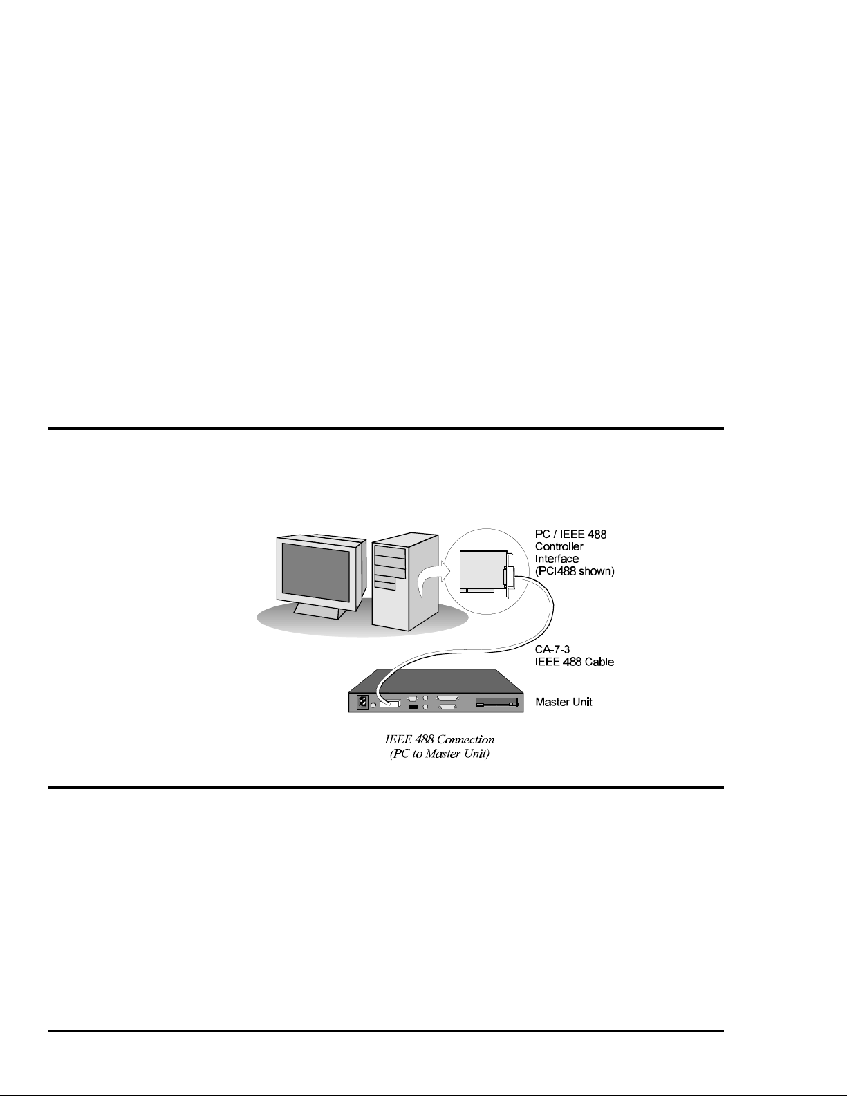
Hardware Connection
For successful data acquisition, the Personal488 controller interface must be properly connected to a
data acquisition device. The following diagram depicts an IEEE 488 connection from a Personal488
PC/IEEE 488 controller interface board to a data acquisition master unit.
Software Products
Driver488/W95 & Driver488/WNT
This driver software integrates IEEE 488.2 control into Windows 95 & Windows NT applications.
Supports the PCI488, AT488pnp, CARD488, AT488, GP488B, and GP488B/MM controller interfaces
(discussed above). Provides true multi-tasking device locking. Specifically designed for the 32-bit
Windows environment. Includes interactive control application for exercising instruments.
2 Personal488 Overview Personal488 User's Manual For Windows95 and Windows NT
Page 9

Personal488/PCI (with PCI488) 2
Introduction……3
The Package……3
PCI488 Specifications……3
Controller Interface……3
Installing the New Hardware & Hardware Drivers……4
Updating the Existing Hardware Drivers……6
Introduction
The Package
The Personal488/PCI, including the IEEE 488 interface board and the Driver488 software, is carefully
inspected, both mechanically and electrically, before shipment. When you receive the product, unpack
all items carefully from the shipping carton and check for any obvious signs of physical damage that
may have occurred during shipment. Report any such damage to the shipping agent immediately.
Remember to retain all shipping materials in the event shipment back to the factory becomes necessary.
The Personal488/PCI (with PCI488) package includes:
• PCI488 "Plug-&-Play" IEEE 488 Bus Interface PCI Board
• Driver488 Software Disks for Windows 95 or Windows NT (Driver488/W95 or Driver488/WNT)
• Personal488 User’s Manual for Windows 95 and Windows NT
PCI488 Specifications
Note:
IEEE 488 Controller Device: IOT7210
Maximum Transfer Rate: 32-bit: 1 Mbyte/s (reads and writes)
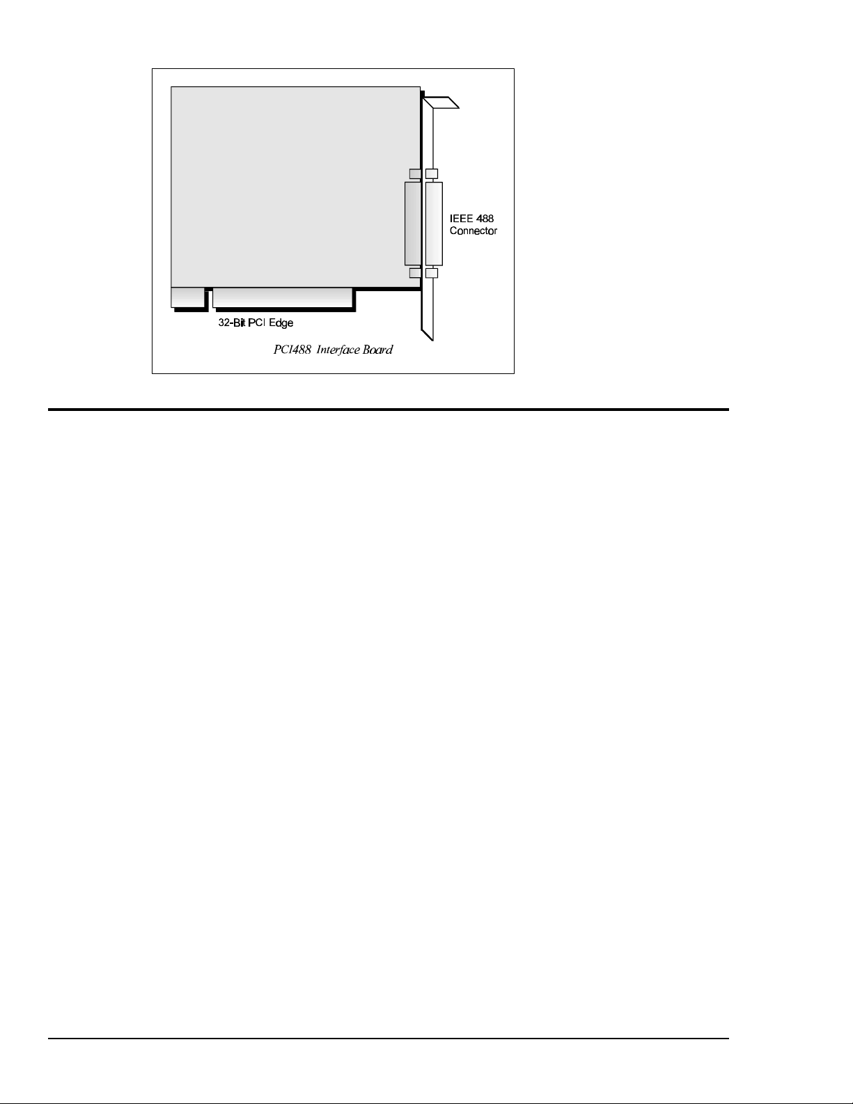
Dimensions: Half-size board; occupies one PCI slot
IEEE 488 Connector: Accepts standard IEEE 488 connector with metric studs
Digital I/O Connector: Standard 9-pin female DSUB connector
Power: 500 mA max @ 5 V from PC
Environment: 0 to 70°C, 0 to 95% RH, non-condensing
Digital I/O: Each signal can source 2 mA @ 3.7 V (6 mA @ 3.2 V) and sink 2 mA @ 0.4 V (6 mA @
Multiple Boards: Up to four PCI488 boards can be installed into one PC
These specifications are subject to change without notice.
0.9 V)
Controller Interface
The PCI488 interface board provides the convenience of plug-and-play installation. The physical
configuration of hardware is not necessary. Instead, after installing your board as described in the
following text, the board is configured automatically.
Personal488 User's Manual For Windows 95 and Windows NT Personal488/PCI (with PCI488) 3
Page 10
Installing the New Hardware & Hardware Drivers
Typical IEEE 488 interface boards are installed into expansion slots inside the PC's system unit.
Typical PCs have the following types of expansion slots
• ISA expansion slots. ISA slots can either be an 8-bit slot with one card-edge receptacle (PC-bus
compatible), or a 16-bit slot with two card-edge receptacles (AT-bus compatible). Eight-bit ISA
boards may be used in either the 8-bit or 16-bit ISA slot, while 16-bit ISA boards may only be
used in the 16-bit ISA slot.
• PCI expansion slots. PCI slots are 32-bit slots, used only by PCI boards.
For technical assistance, see chapter Troubleshooting on page 119 in this manual, or the
troubleshooting section in your PC’s manual. If you are still not sure of the problem, contact the dealer
or manufacturer of your interface board or PC.
Step 1: Installing the PCI488 Interface Board into a PCI Slot
General instructions for installing the board are given since the design of computer cases varies. Refer
to your PC's reference manual whenever in doubt.
1. Turn OFF the power to your computer and any other connected peripheral devices. Follow the
precautions for static electricity discharge.
• Touch a large grounded metal surface to discharge any static electricity build up in your body.
• Avoid any contact with internal parts. Handle cards only by their edges.
• Disconnect the AC power before removing the cover.
2. Unplug all power cords and cables that may interfere from the back of the computer.
3. Remove your computer's cover by removing its mounting screws with a screwdriver. Slide the
cover OFF. If necessary, refer to your PC's manual.
4. Your IEEE 488 controller interface must be installed in a 32-bit PCI-bus expansion slot. Select an
available PCI expansion slot and remove its slot cover by unscrewing the holding screw and sliding
it out. Save this screw for securing the interface after it is installed.
5. To install the IEEE 488 controller interface, carefully align the card edge connector with the PCI
slot on the motherboard, fitting the IEEE 488 port through the rear panel opening. Push the board
down firmly, but gently, until it is well seated.
4 Personal488/PCI (with PCI488) Personal488 User's Manual For Windows95 and Windows NT
Page 11

6. Replace the cover slot holding screw to secure the board in place.
7. Replace the computer's cover and screws. Then reconnect all power cords and cables to the back of
the computer. If available, connect your external data acquisition instrument to the IEEE 488 port
connector on the interface.
8. Turn on your PC.
At this point, the hardware installation is complete. Continue to Step 2.
Step 2: Detecting the PCI488 Interface Board in "Add New Hardware"
1. After installing the IEEE 488 controller interface, turn on your computer. Windows will detect the
new hardware and prompt for a Manufacturer’s Disk.
2. Insert the disk labeled "Driver488 Driver Disk, 1 of 1" into the floppy disk drive. Click OK.
3. The hardware will now be recognized and configured by Windows; the "Add New Hardware
Wizard" will auto-assign an available I/O base address, IRQ (Interrupt), and DMA channel.
(Additional PCI488 interfaces may share the same IRQ and DMA values.)
Continue as prompted to load the interface driver, but DO NOT restart Windows. Select No to
NOT shut down and go directly to the Device Manager to verify the presence of the new hardware
device.
At this point, the hardware detection is complete. Continue to Step 3.
Step 3: Verifying the PCI488 Interface Installation & Driver488 Software Settings
1. To confirm proper installation, open the Control Panel window from the Start > Settings menu,
click on the System icon, and select the Device Manager tab. Look for a device type named
"IEEE488.2 Controllers" and below it, verify the presence of the new hardware device.
2. During Driver488 installation, a new Control Panel applet titled "IEEE 488" was installed under the
Control Panel with default settings selected.
To verify or configure the Driver488 software settings for your IEEE 488 interface(s) and IEEE 488
external device(s), see chapter Driver488/W95 & Driver488/WNT on page 41.
3. Restart Windows and once again verify the hardware installation and Driver488 configuration in
Device Manager.
At this point, the hardware and driver verification is complete. Continue to Step 4.
Step 4: Installing the PCI488 Interface Software Support Files
1. Insert the disk titled "IEEE 488 Software Installation Disk, 1 of 2" into the floppy disk drive.
2. To install, you can do one of the following:
• Select Run from the Start Menu, type in A:\SETUP.EXE, then click OK.
• Go to My Computer or Windows Explorer, double-click on the Floppy Drive icon, then double-
click on the Setup icon.
• Or go to the Control Panel from the Start > Settings menu, double-click on the Add/Remove
Programs icon, then click the Install button.
3. The Installation program will step you through various options on installing these software support
files.
Note: These files are NOT required to get the hardware to work properly, but it is recommended
if any software development is desired or Help files are needed.
4. Any or all of the installed software support files may be removed by going to the Control Panel
from the Start > Settings menu, double-clicking on the Add/Remove Programs icon, then selecting
"Personal IEEE 488 v 2.0", and clicking the Add/Remove… button.
At this point, the installation of software support files is complete.
Personal488 User's Manual For Windows 95 and Windows NT Personal488/PCI (with PCI488) 5
Page 12

Updating the Existing Hardware Drivers
Updating the PCI488 Interface Hardware Drivers
1. Insert the disk titled "Driver488 Driver Disk, 1 of 1" into the floppy disk drive.
2. Open the Control Panel window from the Start > Settings menu, click on the System icon, and
select the Device Manager tab. Look for a device type named "IEEE488.2 Controllers".
3. Highlight the device you want to update under "IEEE488.2 Controllers".
4. Click on the Properties button. Click on the Driver tab.
5. Highlight the driver file named "C:\Windows\System\___488.vxd". (For example,
"…\vpci488.vxd".)
6. Click on the Change Driver button.
7. Select the model that you are updating. Click OK.
Note: DO NOT select the Have Disk... button.
8. Windows will return you to the Driver tab. Click OK. The hardware drivers will now be updated
from the Driver Disk.
9. Windows will prompt you if you wish to restart the system. Select Yes. Otherwise the hardware
will continue to use the outdated drivers until the next time the system is restarted.
6 Personal488/PCI (with PCI488) Personal488 User's Manual For Windows95 and Windows NT
Page 13

Personal488/ATpnp (with AT488pnp) 3
Introduction……7
The Package……7
AT488pnp Specifications……7
Controller Interface……7
Installing the New Hardware & Hardware Drivers……8
Updating the Existing Hardware Drivers……10
Introduction
The Package
The Personal488/ATpnp, including the IEEE 488 interface board and the Driver488 software, is
carefully inspected, both mechanically and electrically, before shipment. When you receive the
product, unpack all items carefully from the shipping carton and check for any obvious signs of
physical damage that may have occurred during shipment. Report any such damage to the shipping
agent immediately. Remember to retain all shipping materials in the event shipment back to the factory
becomes necessary.
The Personal488/ATpnp (with AT488pnp) package includes:
• AT488pnp "Plug-&-Play" IEEE 488 Bus Interface ISA Board
• Driver488 Software Disks for Windows 95 or Windows NT (Driver488/W95 or Driver488/WNT)
• Personal488 User’s Manual for Windows 95 and Windows NT
AT488pnp Specifications
Note:
IEEE 488 Controller Device: IOT7210
Maximum Transfer Rates: 16-bit DMA: 1 Mbyte/s (reads), 800 Kbyte/s (writes)
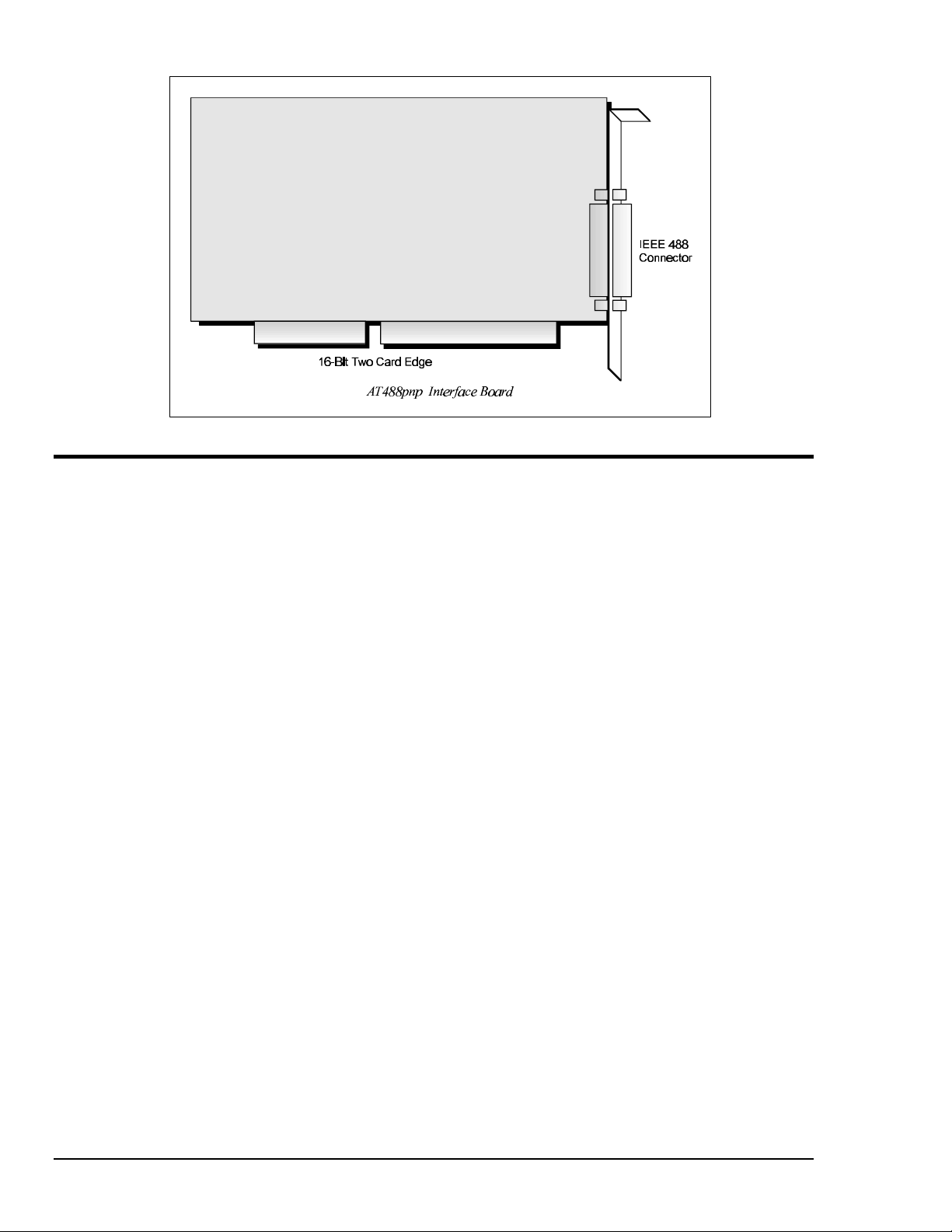
Dimensions: Full-size board, two card edges; occupies one ISA slot
IEEE 488 Connector: Accepts standard IEEE 488 connector with metric studs
Digital I/O Connector: Standard 9-pin female DSUB connector
Power: 1.0 A max @ 5 V from PC
Environment: 0 to 70°C, 0 to 95% RH, non-condensing
DMA: 16-bit DMA on channels 5, 6, and 7
Interrupts: IRQ 3, 4, 5, 7, 10, 11, 12, or 15
Digital I/O: Each signal can source 2 mA @ 3.7 V (6 mA @ 3.2 V) and sink 2 mA @ 0.4 V (6 mA @
Multiple Boards: Up to three AT488pnp boards can be installed into one PC
These specifications are subject to change without notice.
0.9 V)
Controller Interface
The AT488pnp interface board provides the convenience of plug-and-play installation. The physical
configuration of hardware is not necessary. Instead, after installing your board as described in the
following text, the board is configured automatically.
Personal488 User's Manual For Windows 95 and Windows NT Personal488/ATpnp (with AT488pnp) 7
Page 14
Installing the New Hardware & Hardware Drivers
Typical IEEE 488 interface boards are installed into expansion slots inside the PC's system unit.
Typical PCs have the following types of expansion slots
• ISA expansion slots. ISA slots can either be an 8-bit slot with one card-edge receptacle (PC-bus
compatible), or a 16-bit slot with two card-edge receptacles (AT-bus compatible). Eight-bit ISA
boards may be used in either the 8-bit or 16-bit ISA slot, while 16-bit ISA boards may only be
used in the 16-bit ISA slot.
• PCI expansion slots. PCI slots are 32-bit slots, used only by PCI boards.
For technical assistance, see chapter Troubleshooting on page 119 in this manual, or the
troubleshooting section in your PC’s manual. If you are still not sure of the problem, contact the dealer
or manufacturer of your interface board or PC.
Step 1: Installing the AT488pnp Interface Board into an ISA Slot
General instructions for installing the board are given since the design of computer cases varies. Refer
to your PC's reference manual whenever in doubt.
1. Turn OFF the power to your computer and any other connected peripheral devices. Follow the
precautions for static electricity discharge.
• Touch a large grounded metal surface to discharge any static electricity build up in your body.
• Avoid any contact with internal parts. Handle cards only by their edges.
• Disconnect the AC power before removing the cover.
2. Unplug all power cords and cables that may interfere from the back of the computer.
3. Remove your computer's cover by removing its mounting screws with a screwdriver. Slide the
cover OFF. If necessary, refer to your PC's manual.
4. Your IEEE 488 controller interface must be installed in a 16-bit ISA-bus expansion slot. Select an
available ISA expansion slot and remove its slot cover by unscrewing the holding screw and sliding
it out. Save this screw for securing the interface after it is installed.
5. To install the IEEE 488 controller interface, carefully align the card edge connector with the ISA
slot on the motherboard, fitting the IEEE 488 port through the rear panel opening. Push the board
down firmly, but gently, until it is well seated.
8 Personal488/ATpnp (with AT488pnp) Personal488 User's Manual For Windows95 and Windows NT
Page 15

6. Replace the cover slot holding screw to secure the board in place.
7. Replace the computer's cover and screws. Then reconnect all power cords and cables to the back of
the computer. If available, connect your external data acquisition instrument to the IEEE 488 port
connector on the interface.
8. Turn on your PC.
At this point, the hardware installation is complete. Continue to Step 2.
Step 2: Detecting the AT488pnp Interface Board in "Add New Hardware"
1. After installing the IEEE 488 controller interface, turn on your computer. Windows will detect the
new hardware and prompt for a Manufacturer’s Disk.
2. Insert the disk labeled "Driver488 Driver Disk, 1 of 1" into the floppy disk drive. Click OK.
3. The hardware will now be recognized and configured by Windows; the "Add New Hardware
Wizard" will auto-assign an available I/O base address, IRQ (Interrupt), and DMA channel.
(Additional AT488pnp interfaces may share the same IRQ and DMA values.)
Continue as prompted to load the interface driver, but DO NOT restart Windows. Select No to
NOT shut down and go directly to the Device Manager to verify the presence of the new hardware
device.
At this point, the hardware detection is complete. Continue to Step 3.
Step 3: Verifying the AT488pnp Interface Installation & Driver488 Software Settings
1. To confirm proper installation, open the Control Panel window from the Start > Settings menu,
click on the System icon, and select the Device Manager tab. Look for a device type named
"IEEE488.2 Controllers" and below it, verify the presence of the new hardware device.
2. During Driver488 installation, a new Control Panel applet titled "IEEE 488" was installed under the
Control Panel with default settings selected.
To verify or configure the Driver488 software settings for your IEEE 488 interface(s) and IEEE 488
external device(s), see chapter Driver488/W95 & Driver488/WNT on page 41.
3. Restart Windows and once again verify the hardware installation and Driver488 configuration in
Device Manager.
At this point, the hardware and driver verification is complete. Continue to Step 4.
Step 4: Installing the AT488pnp Interface Software Support Files
1. Insert the disk titled "IEEE 488 Software Installation Disk, 1 of 2" into the floppy disk drive.
2. To install, you can do one of the following:
• Select Run from the Start Menu, type in A:\SETUP.EXE, then click OK.
• Go to My Computer or Windows Explorer, double-click on the Floppy Drive icon, then double-
click on the Setup icon.
• Or go to the Control Panel from the Start > Settings menu, double-click on the Add/Remove
Programs icon, then click the Install button.
3. The Installation program will step you through various options on installing these software support
files.
Note: These files are NOT required to get the hardware to work properly, but it is recommended
if any software development is desired or Help files are needed.
4. Any or all of the installed software support files may be removed by going to the Control Panel
from the Start > Settings menu, double-clicking on the Add/Remove Programs icon, then selecting
"Personal IEEE 488 v 2.0", and clicking the Add/Remove… button.
At this point, the installation of software support files is complete.
Personal488 User's Manual For Windows 95 and Windows NT Personal488/ATpnp (with AT488pnp) 9
Page 16

Updating the Existing Hardware Drivers
Updating the AT488pnp Interface Hardware Drivers
1. Insert the disk titled "Driver488 Driver Disk, 1 of 1" into the floppy disk drive.
2. Open the Control Panel window from the Start > Settings menu, click on the System icon, and
select the Device Manager tab. Look for a device type named "IEEE488.2 Controllers".
3. Highlight the device you want to update under "IEEE488.2 Controllers".
4. Click on the Properties button. Click on the Driver tab.
5. Highlight the driver file named "C:\Windows\System\___488.vxd". (For example,
"…\vpci488.vxd".)
6. Click on the Change Driver button.
7. Select the model that you are updating. Click OK.
Note: DO NOT select the Have Disk... button.
8. Windows will return you to the Driver tab. Click OK. The hardware drivers will now be updated
from the Driver Disk.
9. Windows will prompt you if you wish to restart the system. Select Yes. Otherwise the hardware
will continue to use the outdated drivers until the next time the system is restarted.
10 Personal488/ATpnp (with AT488pnp) Personal488 User's Manual For Windows95 and Windows NT
Page 17

Personal488/CARD (with CARD488) 4
Introduction……11
The Package……11
CARD488 Specifications……11
Controller Interface……11
Installing the New Hardware & Hardware Drivers……12
Updating the Existing Hardware Drivers……14
Introduction
The Package
The Personal488/CARD, including the IEEE 488 interface PC Card and the Driver488 software, is
carefully inspected, both mechanically and electrically, before shipment. When you receive the
product, unpack all items carefully from the shipping carton and check for any obvious signs of
physical damage that may have occurred during shipment. Report any such damage to the shipping
agent immediately. Remember to retain all shipping materials in the event shipment back to the factory
becomes necessary.
The Personal488/CARD (with CARD488) package includes:
• CARD488 "Plug-&-Play" IEEE 488 Bus Interface PC Card
• Driver488 Software Disks for Windows 95 or Windows NT (Driver488/W95 or Driver488/WNT)
• Personal488 User’s Manual for Windows 95 and Windows NT
CARD488 Specifications
Note:
IEEE 488 Controller Device: IOT7210
Maximum Transfer Rate: 1 Mbyte/s (reads and writes)
Dimensions: Type II (5 mm) PCMCIA card
Bus Interface: PCMCIA PC Card Standard 2.1
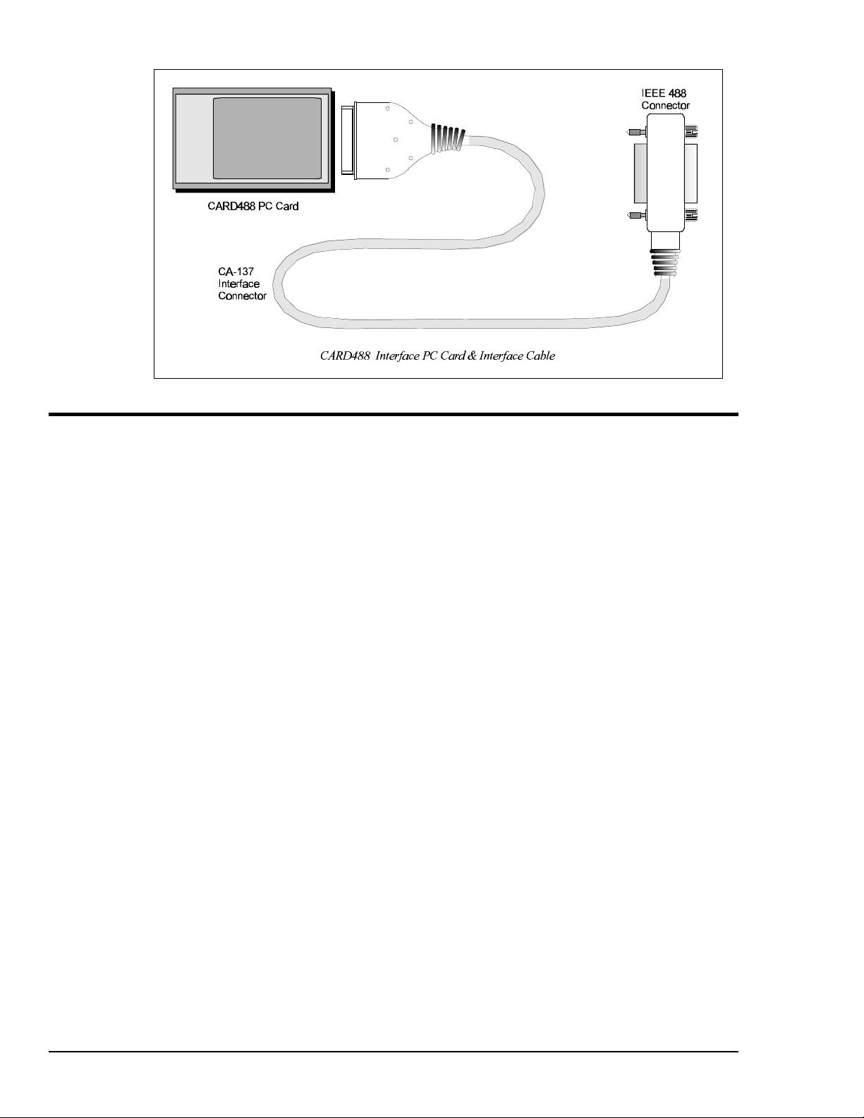
IEEE 488 Connector: Accepts standard IEEE 488 connector with metric studs via custom cable
Cable: PCMCIA to IEEE 488, CA-137 (included)
These specifications are subject to change without notice.
Controller Interface
The CARD488 interface PC Card provides the convenience of plug-and-play installation. The physical
configuration of hardware is not necessary. Instead, after installing your PC Card as described in the
following text, the interface is configured automatically.
Personal488 User's Manual For Windows 95 and Windows NT Personal488/CARD (with CARD488) 11
Page 18
Installing the New Hardware & Hardware Drivers
Unlike typical IEEE 488 interface boards which are installed into expansion slots inside the PC’s
system unit, the CARD488 PC Card interface is installed into the PC Card slot of the computer. The
computer does not need to be turned off.
For technical assistance, see chapter Troubleshooting on page 119 in this manual, or the
troubleshooting section in your PC’s manual. If you are still not sure of the problem, contact the dealer
or manufacturer of your interface board or PC.
Step 1: Installing the CARD488 Interface into a PC Card Slot
Refer to your PC's reference manual whenever in doubt.
1. Install the IEEE 488 controller interface into the PC Card slot of the computer. The computer does
not need to be turned off.
Note: It is assumed the user has a properly installed PC Card adapter in the computer.
At this point, the hardware installation is complete. Continue to Step 2.
Step 2: Detecting the CARD488 Interface in "Add New Hardware"
1. After installing the IEEE 488 controller interface, turn on your computer. Windows will detect the
new hardware and prompt for a Manufacturer’s Disk.
2. Insert the disk labeled "Driver488 Driver Disk, 1 of 1" into the floppy disk drive. Click OK.
3. The hardware will now be recognized and configured by Windows; the "Add New Hardware
Wizard" will auto-assign an available I/O base address, IRQ (Interrupt), and DMA channel.
(Additional CARD488 interfaces may share the same IRQ and DMA values.)
Continue as prompted to load the interface driver, but DO NOT restart Windows. Select No to
NOT shut down and go directly to the Device Manager to verify the presence of the new hardware
device.
At this point, the hardware detection is complete. Continue to Step 3.
12 Personal488/CARD (with CARD488) Personal488 User's Manual For Windows95 and Windows NT
Page 19

Step 3: Verifying the CARD488 Interface Installation & Driver488 Software Settings
1. To confirm proper installation, open the Control Panel window from the Start > Settings menu,
click on the System icon, and select the Device Manager tab. Look for a device type named
"IEEE488.2 Controllers" and below it, verify the presence of the new hardware device.
2. During Driver488 installation, a new Control Panel applet titled "IEEE 488" was installed under the
Control Panel with default settings selected.
To verify or configure the Driver488 software settings for your IEEE 488 interface(s) and IEEE 488
external device(s), see chapter Driver488/W95 & Driver488/WNT on page 41.
3. Restart Windows and once again verify the hardware installation and Driver488 configuration in
Device Manager.
At this point, the hardware and driver verification is complete. Continue to Step 4.
Step 4: Installing the CARD488 Interface Software Support Files
1. Insert the disk titled "IEEE 488 Software Installation Disk, 1 of 2" into the floppy disk drive.
2. To install, you can do one of the following:
• Select Run from the Start Menu, type in A:\SETUP.EXE, then click OK.
• Go to My Computer or Windows Explorer, double-click on the Floppy Drive icon, then double-
click on the Setup icon.
• Or go to the Control Panel from the Start > Settings menu, double-click on the Add/Remove
Programs icon, then click the Install button.
3. The Installation program will step you through various options on installing these software support
files.
Note: These files are NOT required to get the hardware to work properly, but it is recommended
if any software development is desired or Help files are needed.
4. Any or all of the installed software support files may be removed by going to the Control Panel
from the Start > Settings menu, double-clicking on the Add/Remove Programs icon, then selecting
"Personal IEEE 488 v 2.0", and clicking the Add/Remove… button.
At this point, the installation of software support files is complete.
Personal488 User's Manual For Windows 95 and Windows NT Personal488/CARD (with CARD488) 13
Page 20

Updating the Existing Hardware Drivers
Updating the 32-Bit Personal488/CARD Hardware Drivers
1. Insert the disk titled "Driver488 Driver Disk, 1 of 1" into the floppy disk drive.
2. Open the Control Panel window from the Start > Settings menu, click on the System icon, and
select the Device Manager tab. Look for a device type named "IEEE488.2 Controllers".
3. Highlight the device you want to update under "IEEE488.2 Controllers".
4. Click on the Properties button. Click on the Driver tab.
5. Highlight the driver file named "C:\Windows\System\___488.vxd". (For example,
"…\vpci488.vxd".)
6. Click on the Change Driver button.
7. Select the model that you are updating. Click OK.
Note: DO NOT select the Have Disk... button.
8. Windows will return you to the Driver tab. Click OK. The hardware drivers will now be updated
from the Driver Disk.
9. Windows will prompt you if you wish to restart the system. Select Yes. Otherwise the hardware
will continue to use the outdated drivers until the next time the system is restarted.
Updating the 16-Bit Personal488/CARD Installation
1. If an older 16-bit installation for the Personal488/CARD (with CARD488) was done in
Windows 95/NT, then the following steps must be taken. This older installation is identified by the
device description "IEP-488 Personal488/CARD".
Note: The 32-bit installation, which does not require the following steps, is identified by the
device description “Personal488/CARD”. To update the 32-bit driver, follow the
directions under the previous section Updating the 32-Bit Personal488/CARD Hardware
Drivers.
2. To find this device description "IEP-488 Personal488/CARD", open the Control Panel window
from the Start > Settings menu, click on the System icon, and select the Device Manager tab. (The
CARD488 should already have been installed and inserted in the computer).
3. Remove the CARD488 from the computer.
4. Insert the disk labeled "Driver488 Driver Disk, 1 of 1" into the floppy disk drive.
5. To run the file CLEANCRD.BAT found on the "Driver Disk", you can do one of the following:
• Go to My Computer or Windows Explorer, double-click on the Floppy Drive icon, then double-
click on the CLEANCRD.BAT icon.
• Select the MS-DOS prompt from the Start Menu to open the MS-DOS command window, type
in A:\CLEANCRD.BAT and press the <Enter> key.
6. Once the CLEANCRD.BAT program has finished, re-insert the CARD488 into the computer.
7. Windows will detect the new hardware and prompt for a Manufacturer’s Disk. With the disk
labeled “Driver488 Driver Disk, 1 of 1” still in the floppy disk drive, click OK.
8. The hardware will now be recognized and configured by Windows. To confirm proper installation,
open the Control Panel window from the Start > Settings menu, click on the System icon, and select
the Device Manager tab. Look for a device type named "IEEE488.2 Controllers" with the new
hardware device below it.
9. A new Control Panel applet titled "IEEE 488" will exist under the Control Panel with default
settings installed. Refer to the Help documents on changing these settings.
14 Personal488/CARD (with CARD488) Personal488 User's Manual For Windows95 and Windows NT
Page 21

Personal488/AT (with AT488) 5
Introduction……15
The Package……15
AT488 Specifications……15
Configuring the New Hardware……16
Installing the New Hardware & Hardware Drivers……20
Updating the Existing Hardware Drivers……22
Introduction
The Package
The Personal488/AT, including the IEEE 488 interface board and the Driver488 software, is carefully
inspected, both physically and electronically, before shipment. When you receive the product, unpack
all items carefully from the shipping carton and check for any obvious signs of physical damage that
may have occurred during shipment. Report any such damage to the shipping agent immediately.
Remember to retain all shipping materials in the event shipment back to the factory becomes necessary.
The Personal488/AT (with AT488) package includes:
• AT488 IEEE 488 Bus Interface ISA Board
• Driver488 Software Disks for Windows 95 or Windows NT (Driver488/W95 or Driver488/WNT)
• Personal488 User’s Manual for Windows 95 and Windows NT
AT488 Specifications
Note:
IEEE 488 Controller Device: IOT7210
Maximum Transfer Rates: 16-bit DMA: 1 Mbyte/s (reads), 800 Kbyte/s (writes); 8-bit DMA: 330
Dimensions: Full-size board, two card edges; occupies one ISA slot
IEEE 488 Connector: Accepts standard IEEE 488 connector with metric studs
Power: 1.0 A max @ 5 V from PC
Environment: 0 to 70°C, 0 to 95% RH, non-condensing
DMA: 16-bit DMA on channels 5, 6, and 7; 8-bit DMA on channels 0, 1, 2, and 3 (jumper selectable)
Interrupts: IRQ 2, 3, 4, 5, 6, or 7 (8-bit slot); IRQ 3-7, 9-12, 14, or 15 (16-bit slot)
IEEE 488 I/O Base Address: &H02E1, &H22E1, &H42E1, or &H62E1
Multiple Boards: Up to four AT488 boards can be installed, sharing a single DMA channel and
These specifications are subject to change without notice.
Kbyte/s (reads), 220 Kbyte/s (writes)
interrupt line
Personal488 User's Manual For Windows 95 and Windows NT Personal488/AT (with AT488) 15
Page 22
Configuring the New Hardware
The following text will guide you through the setup of your IEEE 488 controller interface. It includes
instructions on how to verify the resource settings of ports in your system, and how to properly
configure the switches/jumpers on your interface board.
To avoid a configuration conflict, you must first verify which I/O addresses, IRQs, and DMAs are
being used by existing ports in your system, prior to configuring and installing the IEEE 488 controller
interface.
Step 1: Verifying/Recording the Current System Settings
The Windows Control Panel enables you to easily determine and configure the I/O addresses, IRQ
setting, and DMA settings in your system for proper operation. Perform the following steps to verify
your system settings.
1. Open the Control Panel window from the Start > Settings menu, click on the System icon, and
select the Device Manager tab. Under the line "Ports (COM & LPT)", look for a list of used ports.
For each port, highlight the port and click on the Properties button.
2. Properties already being used in the system are displayed under the Resources tab. Values NOT
listed are available.
• For each listed port, record which Input/Output (I/O) address, if any, is being used.
• For each listed port, record which Interrupt Request (IRQ) value, if any, is being used.
• For each listed port, record which Direct Memory Access (DMA) value, if any, is being used.
3. Exit Windows and turn the system OFF.
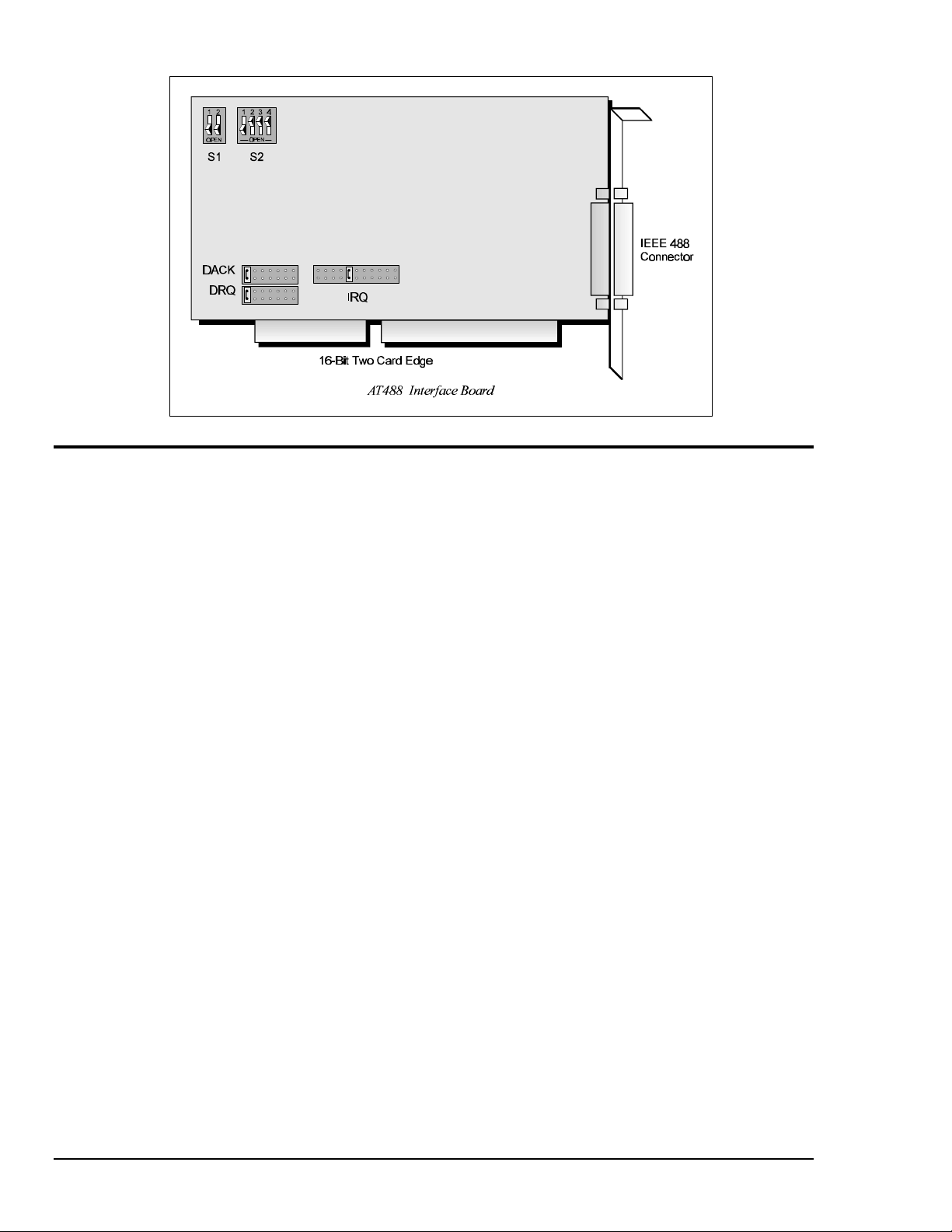
The I/O base address, IRQ, and DMA settings are switch/jumper selectable via the following locations
on the AT488 interface board: One 2-microswitch DIP switch labelled S1, one 4-microswitch DIP
switch labelled S2, two 14-pin headers labelled DACK and DRQ, and one 22-pin header labelled IRQ.
The DIP switch settings, and the arrangement of the jumpers on the headers set the hardware
configuration.
For the next steps, make sure that the I/O address, IRQ, and DMA, set on the interface board are
different from any existing ports in your system. A conflict results when two I/O addresses, IRQs, or
DMAs are the same. (As the exception, additional AT488 interfaces may share the same IRQ and DMA
values.) If there is a conflict, perform the following steps to select new switch/jumper settings.
16 Personal488/AT (with AT488) Personal488 User's Manual For Windows95 and Windows NT
Page 23
Step 2: Configuring the AT488 Interface I/O Base Address
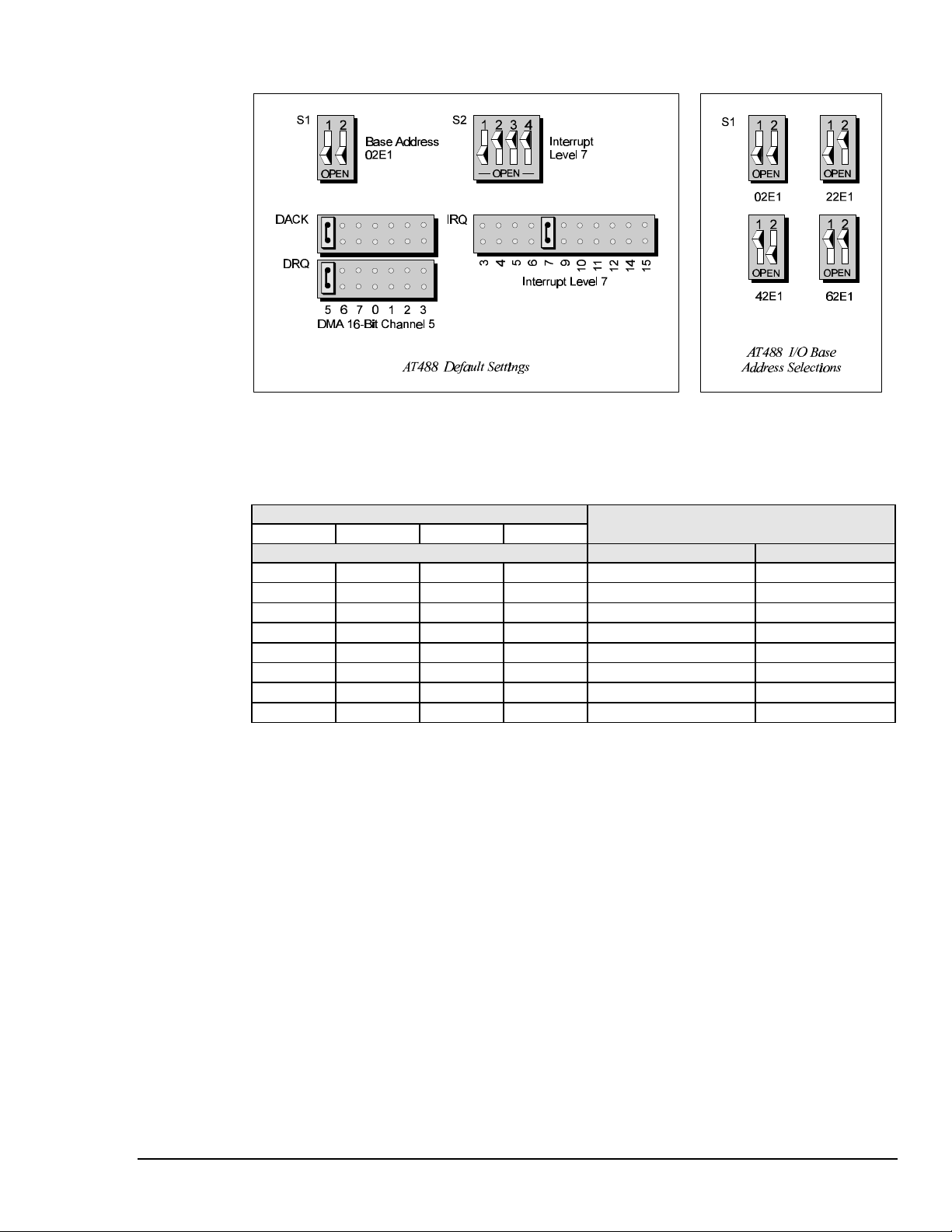
1. The factory default I/O base address is 02E1. If this creates a conflict, reset switch S1 according to
the figure and following table. The register addresses will be automatically relocated at fixed
offsets from the base address.
2. If reset, record the new Input/Output (I/O) address being used.
Selected I/O Base Address Register
02E1 22E1 42E1 62E1
Automatic Offset Addresses Read Register Write Register
02E1 22E1 42E1 62E1 Data In Data Out
06E1 26E1 46E1 66E1 Interrupt Status 1 Interrupt Mask 1
0AE1 2AE1 4AE1 6AE1 Interrupt Status 2 Interrupt Mask 2
0EE1 2EE1 4EE1 6EE1 Serial Poll Status Serial Poll Mode
12E1 32E1 52E1 72E1 Address Status Address Mode
16E1 36E1 56E1 76E1 CMD Pass Through Auxiliary Mode
1AE1 3AE1 5AE1 7AE1 Address 0 Address 0/1
1EE1 3EE1 5EE1 7EE1 Address 1 End of String
The I/O base address sets the addresses used by the computer to communicate with the IEEE 488
interface hardware on the board. The address is normally specified in hexadecimal and can be 02E1,
22E1, 42E1, or 62E1. The registers of the IOT7210 IEEE 488 controller chip and other auxiliary
registers are then located at fixed offsets from the base address.
Most versions of Driver488 are capable of managing as many as four IEEE 488 interfaces. To do so,
the interface configurations must be arranged to avoid conflict among themselves. No two boards may
have the same I/O address; but they may, and usually should, have the same DMA channel and
interrupt level.
Personal488 User's Manual For Windows 95 and Windows NT Personal488/AT (with AT488) 17
Page 24
Step 3: Configuring the AT488 Interface Interrupt (IRQ)
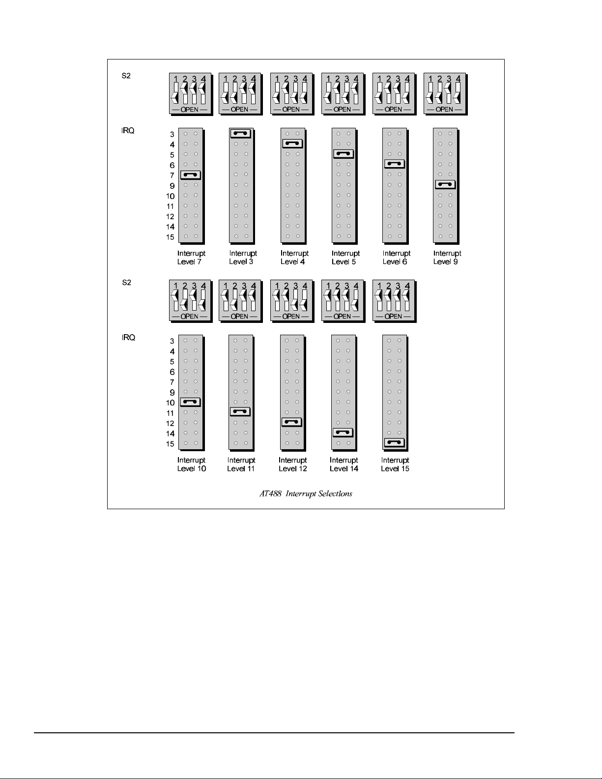
1. The factory default Interrupt (IRQ) is 7. If this creates a conflict, reset switch S2 and jumper IRQ
according to the figure. The switch and jumper settings must both indicate the same interrupt level
for correct operation with interrupts.
2. If reset, record the new Interrupt (IRQ) being used.
The AT488 interface board may be set to interrupt the PC on the occurrence of certain hardware
conditions. The main board interrupt may be set to IRQ level 3 through 7, 9 through 12, 14, or 15.
Interrupts 10 through 15 are only available in a 16-bit slot on an AT-class machine. Interrupt 9
becomes synonymous with Interrupt 2 when used in a PC/XT bus.
The selected interrupt may be shared among several AT488s in the same PC/AT chassis. The AT488
adheres to the “AT-style” interrupt sharing conventions. When the AT488 requires service, the IRQ
jumper determines which PC interrupt level is triggered. When an interrupt occurs, the interrupting
device must be reset by writing to an I/O address which is different for each interrupt level. The switch
settings determine the I/O address to which the board’s interrupt rearm circuitry responds.
18 Personal488/AT (with AT488) Personal488 User's Manual For Windows95 and Windows NT
Page 25
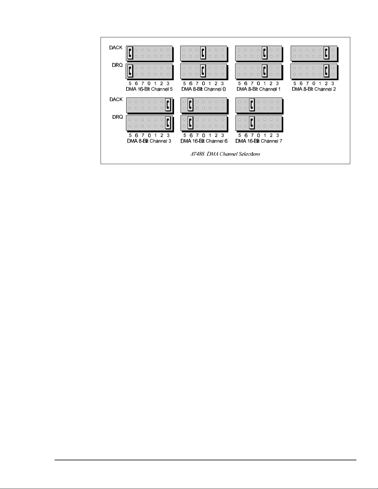
Step 4: Configuring the AT488 Interface DMA Channel
1. The factory default DMA channel is 5. If this creates a conflict, reset jumpers DACK and DRQ
according to the figure. Both the DRQ and DACK jumpers must be set to the desired DMA channel
for proper operation.
2. If reset, record the new DMA channel being used.
Direct Memory Access (DMA) is a high-speed method of transferring data from or to a peripheral, such
as a digitizing oscilloscope, to or from the PC’s memory. The AT class machine has seven DMA
channels. Channels 0 to 3 (8-bit), 5, 6, and 7 (16-bit) are available only in a 16-bit slot on a PC/ATclass machine. Channel 2 is usually used by the floppy disk controller, and is unavailable. Channel 3
is often used by the hard disk controller in PCs, XTs, and the PS/2 with the ISA bus, but is usually not
used in ATs. Channels 5 to 7 are 16-bit DMA channels and offer the highest throughput (up to 1
Megabyte per second). Channels 0 to 3 are 8-bit DMA channels and although slower, they offer
compatibility with existing GP488B applications that only made use of 8-bit DMA channels. Under
some rare conditions, it is possible for high-speed transfers on DMA Channel 1 to demand so much of
the available bus bandwidth that simultaneous access of a floppy controller will be starved for data due
to the relative priorities of the two channels.
Personal488 User's Manual For Windows 95 and Windows NT Personal488/AT (with AT488) 19
Page 26

Installing the New Hardware & Hardware Drivers
Typical IEEE 488 interface boards are installed into expansion slots inside the PC's system unit.
Typical PCs have the following types of expansion slots
• ISA expansion slots. ISA slots can either be an 8-bit slot with one card-edge receptacle (PC-bus
compatible), or a 16-bit slot with two card-edge receptacles (AT-bus compatible). Eight-bit ISA
boards may be used in either the 8-bit or 16-bit ISA slot, while 16-bit ISA boards may only be
used in the 16-bit ISA slot.
• PCI expansion slots. PCI slots are 32-bit slots, used only by PCI boards.
For technical assistance, see chapter Troubleshooting on page 119 in this manual, or the
troubleshooting section in your PC’s manual. If you are still not sure of the problem, contact the dealer
or manufacturer of your interface board or PC.
Step 1: Installing the AT488 Interface Board into an ISA Slot
General instructions for installing the board are given since the design of computer cases varies. Refer
to your PC's reference manual whenever in doubt.
1. Turn OFF the power to your computer and any other connected peripheral devices. Follow the
precautions for static electricity discharge.
• Touch a large grounded metal surface to discharge any static electricity build up in your body.
• Avoid any contact with internal parts. Handle cards only by their edges.
• Disconnect the AC power before removing the cover.
2. Unplug all power cords and cables that may interfere from the back of the computer.
3. Remove your computer's cover by removing its mounting screws with a screwdriver. Slide the
cover OFF. If necessary, refer to your PC's manual.
4. Your IEEE 488 controller interface must be installed in a 16-bit ISA-bus expansion slot. Select an
available ISA expansion slot and remove its slot cover by unscrewing the holding screw and sliding
it out. Save this screw for securing the interface after it is installed.
5. To install the IEEE 488 controller interface, carefully align the card edge connector with the ISA
slot on the motherboard, fitting the IEEE 488 port through the rear panel opening. Push the board
down firmly, but gently, until it is well seated.
6. Replace the cover slot holding screw to secure the board in place.
7. Replace the computer's cover and screws. Then reconnect all power cords and cables to the back of
the computer. If available, connect your external data acquisition instrument to the IEEE 488 port
connector on the interface.
8. Turn on your PC.
At this point, the hardware installation is complete. Continue to Step 2.
Step 2: Detecting the AT488 Interface Board in "Add New Hardware"
1. After installing the IEEE 488 controller interface, turn on your computer. Windows will detect the
new hardware and prompt for a Manufacturer’s Disk.
2. Insert the disk labeled "Driver488 Driver Disk, 1 of 1" into the floppy disk drive. Click OK.
3. The hardware will now be recognized by Windows; the "Add New Hardware Wizard" will assign
the available I/O base address, IRQ (Interrupt), and DMA channel, which were configured earlier.
(Additional AT488 interfaces may use the same IRQ and DMA values.)
Continue as prompted to load the interface driver, but DO NOT restart Windows. Select No to
NOT shut down and go directly to the Device Manager to verify the presence of the new hardware
device.
At this point, the hardware detection is complete. Continue to Step 3.
20 Personal488/AT (with AT488) Personal488 User's Manual For Windows95 and Windows NT
Page 27

Step 3: Verifying the AT488 Interface Installation & Driver488 Software Settings
1. To confirm proper installation, open the Control Panel window from the Start > Settings menu,
click on the System icon, and select the Device Manager tab. Look for a device type named
"IEEE488.2 Controllers" and below it, verify the presence of the new hardware device.
2. During Driver488 installation, a new Control Panel applet titled "IEEE 488" was installed under the
Control Panel with default settings selected.
To verify or configure the Driver488 software settings for your IEEE 488 interface(s) and IEEE 488
external device(s), see chapter Driver488/W95 & Driver488/WNT on page 41.
• When the I/O base address, IRQ (Interrupt), and DMA channel settings match the jumpered
board, select OK and restart Windows below.
• If any of these settings do not match, manually reset each value. When all of the settings are
correct, select OK and restart Windows below.
3. Restart Windows and once again verify the hardware installation and Driver488 configuration in
Device Manager.
At this point, the hardware and driver verification is complete. Continue to Step 4.
Step 4: Installing the AT488 Interface Software Support Files
1. Insert the disk titled "IEEE 488 Software Installation Disk, 1 of 2" into the floppy disk drive.
2. To install, you can do one of the following:
• Select Run from the Start Menu, type in A:\SETUP.EXE, then click OK.
• Go to My Computer or Windows Explorer, double-click on the Floppy Drive icon, then double-
click on the Setup icon.
• Or go to the Control Panel from the Start > Settings menu, double-click on the Add/Remove
Programs icon, then click the Install button.
3. The Installation program will step you through various options on installing these software support
files.
Note: These files are NOT required to get the hardware to work properly, but it is recommended
if any software development is desired or Help files are needed.
4. Any or all of the installed software support files may be removed by going to the Control Panel
from the Start > Settings menu, double-clicking on the Add/Remove Programs icon, then selecting
"Personal IEEE 488 v 2.0", and clicking the Add/Remove… button.
At this point, the installation of software support files is complete.
Personal488 User's Manual For Windows 95 and Windows NT Personal488/AT (with AT488) 21
Page 28

Updating the Existing Hardware Drivers
Updating the AT488 Interface Hardware Drivers
1. Insert the disk titled "Driver488 Driver Disk, 1 of 1" into the floppy disk drive.
2. Open the Control Panel window from the Start > Settings menu, click on the System icon, and
select the Device Manager tab. Look for a device type named "IEEE488.2 Controllers".
3. Highlight the device you want to update under "IEEE488.2 Controllers".
4. Click on the Properties button. Click on the Driver tab.
5. Highlight the driver file named "C:\Windows\System\___488.vxd". (For example,
"…\vpci488.vxd".)
6. Click on the Change Driver button.
7. Select the model that you are updating. Click OK.
Note: DO NOT select the Have Disk... button.
8. Windows will return you to the Driver tab. Click OK. The hardware drivers will now be updated
from the Driver Disk.
9. Windows will prompt you if you wish to restart the system. Select Yes. Otherwise the hardware
will continue to use the outdated drivers until the next time the system is restarted.
22 Personal488/AT (with AT488) Personal488 User's Manual For Windows95 and Windows NT
Page 29

Personal488 (with GP488B) 6
Introduction……23
The Package……23
GP488B Specifications……23
Configuring the New Hardware……24
Installing the New Hardware & Hardware Drivers……28
Updating the Existing Hardware Drivers……30
Configuring Other Hardware Settings……31
Introduction
The Package
The Personal488, including the IEEE 488 interface board and the Driver488 software, is carefully
inspected, both mechanically and electrically, before shipment. When you receive the product, unpack
all items carefully from the shipping carton and check for any obvious signs of physical damage that
may have occurred during shipment. Report any such damage to the shipping agent immediately.
Remember to retain all shipping materials in the event shipment back to the factory becomes necessary.
The Personal488 (with GP488B) package includes:
• GP488B IEEE 488 Bus Interface ISA Board
• Driver488 Software Disks for Windows 95 or Windows NT (Driver488/W95 or Driver488/WNT)
• Personal488 User’s Manual for Windows 95 and Windows NT
GP488B Specifications
Note:
IEEE 488 Controller Device: IOT7210
Maximum Transfer Rate: 8-bit DMA: 330 Kbyte/s (reads and writes)
Dimensions: Half-size board, one card edge; occupies one ISA slot
IEEE 488 Connector: Accepts standard IEEE 488 connector with metric studs
Power: 650 mA max @ 5 V from PC
Environment: 0 to 70°C, 0 to 95% RH, non-condensing
DMA: 8-bit DMA on channels 0, 1, 2, and 3 (jumper selectable)
Interrupts: IRQ 2, 3, 4, 5, 6, or 7
IEEE 488 I/O Base Address: &H02E1, &H22E1, &H42E1, or &H62E1
Multiple Boards: Up to four GP488B boards can be installed, sharing a single DMA channel and
These specifications are subject to change without notice.
interrupt line
Personal488 User's Manual For Windows 95 and Windows NT Personal488 (with GP488B) 23
Page 30
Configuring the New Hardware
The following text will guide you through the setup of your IEEE 488 controller interface. It includes
instructions on how to verify the resource settings of ports in your system, and how to properly
configure the switches/jumpers on your interface board.
To avoid a configuration conflict, you must first verify which I/O addresses, IRQs, and DMAs are
being used by existing ports in your system, prior to configuring and installing the IEEE 488 controller
interface.
Step 1: Verifying/Recording the Current System Settings
The Windows Control Panel enables you to easily determine and configure the I/O addresses, IRQ
setting, and DMA settings in your system for proper operation. Perform the following steps to verify
your system settings.
1. Open the Control Panel window from the Start > Settings menu, click on the System icon, and
select the Device Manager tab. Under the line "Ports (COM & LPT)", look for a list of used ports.
For each port, highlight the port and click on the Properties button.
2. Properties already being used in the system are displayed under the Resources tab. Values NOT
listed are available.
• For each listed port, record which Input/Output (I/O) address, if any, is being used.
• For each listed port, record which Interrupt Request (IRQ) value, if any, is being used.
• For each listed port, record which Direct Memory Access (DMA) value, if any, is being used.
3. Exit Windows and turn the system OFF.
The I/O base address, IRQ, and DMA settings are switch/jumper selectable via the following locations
on the GP488B interface board: One 8-microswitch DIP switch labelled SW1, two 12-pin headers
labelled J3 and J4, and one 3-pin header labelled J5. The DIP switch settings, and the arrangement of
the jumpers on the headers set the hardware configuration.
For the next steps, make sure that the I/O address, IRQ, and DMA, set on the interface board are
different from any existing ports in your system. A conflict results when two I/O addresses, IRQs, or
DMAs are the same. (As the exception, additional GP488B interfaces may share the same IRQ and
DMA values.) If there is a conflict, perform the following steps to select new switch/jumper settings.
24 Personal488 (with GP488B) Personal488 User's Manual For Windows95 and Windows NT
Page 31
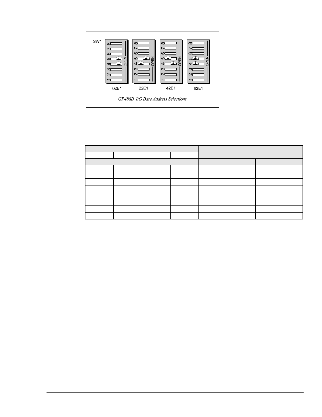
Step 2: Configuring the GP488B Interface I/O Base Address
1. The factory default I/O base address is 02E1. If this creates a conflict, reset SW1 microswitches 4
and 5 according to the figure and following table. The register addresses will be automatically
relocated at fixed offsets from the base address.
2. If reset, record the new Input/Output (I/O) address being used.
Selected I/O Base Address Register
02E1 22E1 42E1 62E1
Automatic Offset Addresses Read Register Write Register
02E1 22E1 42E1 62E1 Data In Data Out
06E1 26E1 46E1 66E1 Interrupt Status 1 Interrupt Mask 1
0AE1 2AE1 4AE1 6AE1 Interrupt Status 2 Interrupt Mask 2
0EE1 2EE1 4EE1 6EE1 Serial Poll Status Serial Poll Mode
12E1 32E1 52E1 72E1 Address Status Address Mode
16E1 36E1 56E1 76E1 CMD Pass Through Auxiliary Mode
1AE1 3AE1 5AE1 7AE1 Address 0 Address 0/1
1EE1 3EE1 5EE1 7EE1 Address 1 End of String
The I/O base address sets the addresses used by the computer to communicate with the IEEE 488
interface hardware on the board. The address is normally specified in hexadecimal and can be 02E1,
22E1, 42E1, or 62E1. The registers of the IOT7210 IEEE 488 controller chip and other auxiliary
registers are then located at fixed offsets from the base address.
Most versions of Driver488 are capable of managing as many as four IEEE 488 interfaces. To do so,
the interface configurations must be arranged to avoid conflict among themselves. No two boards may
have the same I/O address; but they may, and usually should, have the same DMA channel and
interrupt level.
Personal488 User's Manual For Windows 95 and Windows NT Personal488 (with GP488B) 25
Page 32

Step 3: Configuring the GP488B Interface Interrupt (IRQ)
1. The factory default Interrupt (IRQ) is 7. If this creates a conflict, reset SW1 microswitches 1, 2,
and 3, and jumper J4 according to the figure. The switch and jumper settings must both indicate the
same interrupt level for correct operation with interrupts.
2. If reset, record the new Interrupt (IRQ) being used.
The GP488B interface board may be set to interrupt the PC on the occurrence of certain hardware
conditions. The level of the interrupt generated is set by J4. The GP488B adheres to the “AT-style”
interrupt sharing conventions. When an interrupt occurs, the interrupting device must be reset by
writing to I/O address 02FX, where X is the interrupt level (from 0 to 7). This interrupt response level
is set by switches 1, 2, and 3 of SW1 which must be set to correspond to the J4 interrupt level setting.
26 Personal488 (with GP488B) Personal488 User's Manual For Windows95 and Windows NT
Page 33
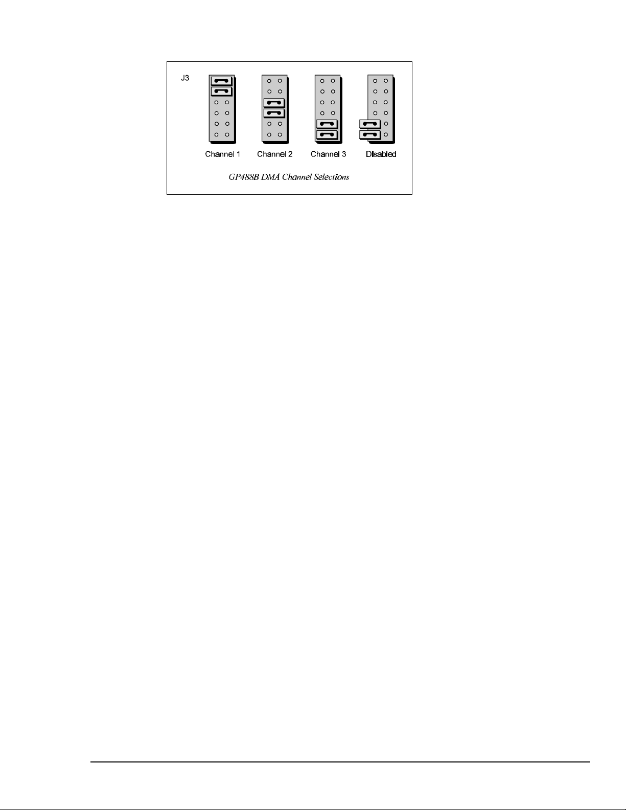
Step 4: Configuring the GP488B Interface DMA Channel
1. The factory default DMA channel is 1. If this creates a conflict, reset jumper J3 according to the
figure.
2. If reset, record the new DMA channel being used.
Direct Memory Access (DMA) is a high-speed method of transferring data from or to a peripheral, such
as a digitizing oscilloscope, to or from the PC’s memory. The PC has four DMA channels, but Channel
0 (Disabled) is used for memory refresh and is not available for peripheral data transfer. Channel 2 is
usually used by the floppy disk controller, and is also unavailable. Channel 3 is often used by the hard
disk controller in PCs, XTs, and the PS/2 with the ISA bus, but is usually not used in ATs. So,
depending on your hardware, DMA Channels 1 and possibly Channel 3 are available. Under some rare
conditions, it is possible for high-speed transfers on DMA Channel 1 to demand so much of the
available bus bandwidth that simultaneous access of a floppy controller will be starved for data due to
the relative priorities of the two channels.
Personal488 User's Manual For Windows 95 and Windows NT Personal488 (with GP488B) 27
Page 34

Installing the New Hardware & Hardware Drivers
Typical IEEE 488 interface boards are installed into expansion slots inside the PC's system unit.
Typical PCs have the following types of expansion slots:
• ISA expansion slots. ISA slots can either be an 8-bit slot with one card-edge receptacle (PC-bus
compatible), or a 16-bit slot with two card-edge receptacles (AT-bus compatible). Eight-bit ISA
boards may be used in either the 8-bit or 16-bit ISA slot, while 16-bit ISA boards may only be
used in the 16-bit ISA slot.
• PCI expansion slots. PCI slots are 32-bit slots, used only by PCI boards.
For technical assistance, see chapter Troubleshooting on page 119 in this manual, or the
troubleshooting section in your PC’s manual. If you are still not sure of the problem, contact the dealer
or manufacturer of your interface board or PC.
Step 1: Installing the GP488B Interface Board into an ISA Slot
General instructions for installing the board are given since the design of computer cases varies. Refer
to your PC's reference manual whenever in doubt.
1. Turn OFF the power to your computer and any other connected peripheral devices. Follow the
precautions for static electricity discharge.
• Touch a large grounded metal surface to discharge any static electricity build up in your body.
• Avoid any contact with internal parts. Handle cards only by their edges.
• Disconnect the AC power before removing the cover.
2. Unplug all power cords and cables that may interfere from the back of the computer.
3. Remove your computer's cover by removing its mounting screws with a screwdriver. Slide the
cover OFF. If necessary, refer to your PC's manual.
4. Your IEEE 488 controller interface must be installed in an 8-bit ISA-bus expansion slot. Select an
available ISA expansion slot and remove its slot cover by unscrewing the holding screw and sliding
it out. Save this screw for securing the interface after it is installed.
5. To install the IEEE 488 controller interface, carefully align the card edge connector with the ISA
slot on the motherboard, fitting the IEEE 488 port through the rear panel opening. Push the board
down firmly, but gently, until it is well seated.
6. Replace the cover slot holding screw to secure the board in place.
7. Replace the computer's cover and screws. Then reconnect all power cords and cables to the back of
the computer. If available, connect your external data acquisition instrument to the IEEE 488 port
connector on the interface.
8. Turn on your PC.
At this point, the hardware installation is complete. Continue to Step 2.
Step 2: Detecting the GP488B Interface Board in "Add New Hardware"
1. After installing the IEEE 488 controller interface, turn on your computer. Windows will detect the
new hardware and prompt for a Manufacturer’s Disk.
2. Insert the disk labeled "Driver488 Driver Disk, 1 of 1" into the floppy disk drive. Click OK.
3. The hardware will now be recognized by Windows; the "Add New Hardware Wizard" will assign
the available I/O base address, IRQ (Interrupt), and DMA channel, which were configured earlier.
(Additional GP488B interfaces may use the same IRQ and DMA values.)
Continue as prompted to load the interface driver, but DO NOT restart Windows. Select No to
NOT shut down and go directly to the Device Manager to verify the presence of the new hardware
device.
At this point, the hardware detection is complete. Continue to Step 3.
28 Personal488 (with GP488B) Personal488 User's Manual For Windows95 and Windows NT
Page 35

Step 3: Verifying the GP488B Interface Installation & Driver488 Software Settings
1. To confirm proper installation, open the Control Panel window from the Start > Settings menu,
click on the System icon, and select the Device Manager tab. Look for a device type named
"IEEE488.2 Controllers" and below it, verify the presence of the new hardware device.
2. During Driver488 installation, a new Control Panel applet titled "IEEE 488" was installed under the
Control Panel with default settings selected.
To verify or configure the Driver488 software settings for your IEEE 488 interface(s) and IEEE 488
external device(s), see chapter Driver488/W95 & Driver488/WNT on page 41.
• When the I/O base address, IRQ (Interrupt), and DMA channel settings match the jumpered
board, select OK and restart Windows below.
• If any of these settings do not match, manually reset each value. When all of the settings are
correct, select OK and restart Windows below.
3. Restart Windows and once again verify the hardware installation and Driver488 configuration in
Device Manager.
At this point, the hardware and driver verification is complete. Continue to Step 4.
Step 4: Installing the GP488B Interface Software Support Files
1. Insert the disk titled "IEEE 488 Software Installation Disk, 1 of 2" into the floppy disk drive.
2. To install, you can do one of the following:
• Select Run from the Start Menu, type in A:\SETUP.EXE, then click OK.
• Go to My Computer or Windows Explorer, double-click on the Floppy Drive icon, then double-
click on the Setup icon.
• Or go to the Control Panel from the Start > Settings menu, double-click on the Add/Remove
Programs icon, then click the Install button.
3. The Installation program will step you through various options on installing these software support
files.
Note: These files are NOT required to get the hardware to work properly, but it is recommended
if any software development is desired or Help files are needed.
4. Any or all of the installed software support files may be removed by going to the Control Panel
from the Start > Settings menu, double-clicking on the Add/Remove Programs icon, then selecting
"Personal IEEE 488 v 2.0", and clicking the Add/Remove… button.
At this point, the installation of software support files is complete.
Personal488 User's Manual For Windows 95 and Windows NT Personal488 (with GP488B) 29
Page 36

Updating the Existing Hardware Drivers
Updating the GP488B Interface Hardware Drivers
1. Insert the disk titled "Driver488 Driver Disk, 1 of 1" into the floppy disk drive.
2. Open the Control Panel window from the Start > Settings menu, click on the System icon, and
select the Device Manager tab. Look for a device type named "IEEE488.2 Controllers".
3. Highlight the device you want to update under "IEEE488.2 Controllers".
4. Click on the Properties button. Click on the Driver tab.
5. Highlight the driver file named "C:\Windows\System\___488.vxd". (For example,
"…\vpci488.vxd".)
6. Click on the Change Driver button.
7. Select the model that you are updating. Click OK.
Note: DO NOT select the Have Disk... button.
8. Windows will return you to the Driver tab. Click OK. The hardware drivers will now be updated
from the Driver Disk.
9. Windows will prompt you if you wish to restart the system. Select Yes. Otherwise the hardware
will continue to use the outdated drivers until the next time the system is restarted.
30 Personal488 (with GP488B) Personal488 User's Manual For Windows95 and Windows NT
Page 37

Configuring Other Hardware Settings
Configuring the GP488B Interface Wait State
The GP488B is fast enough to be compatible with virtually every PC/XT/AT-compatible computer on
the market. Even if the computer is very fast, the processor is normally slowed to 8 MHz or below
when accessing the I/O channel. If the I/O channel runs faster than 8 MHz, it may be faster than the
GP488B board. If you suspect this is a problem, the computer can be made to wait for the GP488B by
enabling wait states. Increasing the number of wait states slows down access to the GP488B board, but
the overall performance degradation is usually only a few percent.
Configuring the GP488B Interface Internal Clock
The IEEE 488 bus interface circuitry requires a master clock. This clock is normally connected to an
on-board 8 MHz clock oscillator. However, some compatible IEEE 488 interface boards connect this
clock to the PC’s own clock signal. Using the PC clock to drive the IEEE 488 bus clock is not
recommended because the PC clock frequency depends on the model of computer. A standard PC has
a 4.77 MHz clock, while an AT might have a 6 MHz or 8 MHz clock. Other manufacturers’ computers
may have almost any frequency clock. If you are using a software package designed for an interface
board (that derived its clock from the PC clock) and you need to do the same to use GP488B with that
particular software, the clock source can be changed. However, the clock frequency must never be
greater than 8 MHz, and clock frequency must be correctly entered in the Driver488 software.
Personal488 User's Manual For Windows 95 and Windows NT Personal488 (with GP488B) 31
Page 38

- Notes
32 Personal488 (with GP488B) Personal488 User's Manual For Windows95 and Windows NT
Page 39

Personal488/MM (with GP488B/MM) 7
Introduction……33
The Package……33
GP488B/MM Specifications……33
Configuring the New Hardware……34
Installing the New Hardware & Hardware Drivers……38
Updating the Existing Hardware Drivers……40
Configuring Other Hardware Settings……40
Introduction
The Package
The Personal488/MM, including the IEEE 488 interface board and the Driver488 software, is carefully
inspected, both mechanically and electrically, before shipment. When you receive the product, unpack
all items carefully from the shipping carton and check for any obvious signs of physical damage that
may have occurred during shipment. Report any such damage to the shipping agent immediately.
Remember to retain all shipping materials in the event shipment back to the factory becomes necessary.
The Personal488/MM (with GP488B/MM) package includes:
• GP488B/MM IEEE 488 Bus Interface PC/104 Board
• Driver488 Software Disks for Windows 95 or Windows NT (Driver488/W95 or Driver488/WNT)
• Personal488 User’s Manual for Windows 95 and Windows NT
GP488B/MM Specifications
Note:
IEEE 488 Controller Device: IOT7210
Maximum Transfer Rate: 8-bit DMA: 330 Kbyte/s (reads and writes)
Connector: 26-pin header ribbon cable to IEEE 488 standard connector
Power: 650 mA @ 5 V from PC
Environment: 0 to 70°C; 0 to 95% RH, non-condensing
DMA: 8-bit DMA on channels 0, 1, 2., and 3 (jumper selectable)
Interrupts: IRQ 2, 3, 4, 5, 6, or 7
IEEE 488 Base I/O Addresses: &H02E1, &H22E1, &H42E1, or &H62E1
(1) GP488B/MM is only compatible with the Ampro PC/104. (2) Only GP488B/MM
Revision B is discussed in this manual. (3) Microswitches 6, 7, and 8 on switch SW1 do not
have a function on this board. (4) These specifications are subject to change without notice.
Personal488 User's Manual For Windows 95 and Windows NT Personal488/MM (with GP488B/MM) 33
Page 40

Configuring the New Hardware
The following text will guide you through the setup of your IEEE 488 controller interface. It includes
instructions on how to verify the resource settings of ports in your system, and how to properly
configure the switches/jumpers on your interface board.
To avoid a configuration conflict, you must first verify which I/O addresses, IRQs, and DMAs are
being used by existing ports in your system, prior to configuring and installing the IEEE 488 controller
interface.
Step 1: Verifying/Recording the Current System Settings
The Windows Control Panel enables you to easily determine and configure the I/O addresses, IRQ
setting, and DMA settings in your system for proper operation. Perform the following steps to verify
your system settings.
1. Open the Control Panel window from the Start > Settings menu, click on the System icon, and
select the Device Manager tab. Under the line "Ports (COM & LPT)", look for a list of used ports.
For each port, highlight the port and click on the Properties button.
2. Properties already being used in the system are displayed under the Resources tab. Values NOT
listed are available.
• For each listed port, record which Input/Output (I/O) address, if any, is being used.
• For each listed port, record which Interrupt Request (IRQ) value, if any, is being used.
• For each listed port, record which Direct Memory Access (DMA) value, if any, is being used.
3. Exit Windows and turn the system OFF.
Note:
There is only one revision level of the GP488B/MM board which is currently supported by 32-bit
Driver488 software, Revision B. Consequently, only GP488B/MM Revision B is discussed in this
manual.
34 Personal488/MM (with GP488B/MM) Personal488 User's Manual For Windows95 and Windows NT
(1) GP488B/MM is only compatible with the Ampro PC/104. (2) Only GP488B/MM
Revision B is discussed in this manual. (3) Microswitches 6, 7, and 8 on switch SW1 do not
have a function on this board.
Page 41

The I/O base address, IRQ, and DMA settings are switch/jumper selectable via the following locations
on the GP488B/MM interface board: One 8-microswitch DIP switch labelled SW1, two 12-pin headers
labelled JP2 and JP3, and one 3-pin header labelled JP1. The DIP switch settings, and the arrangement
of the jumpers on the headers set the hardware configuration.
For the next steps, make sure that the I/O address, IRQ, and DMA, set on the interface board are
different from any existing ports in your system. A conflict results when two I/O addresses, IRQs, or
DMAs are the same. (As the exception, additional GP488B interfaces may share the same IRQ and
DMA values.) If there is a conflict, perform the following steps to select new switch/jumper settings.
Step 2: Configuring the GP488B/MM Interface I/O Base Address
1. The factory default I/O base address is 02E1. If this creates a conflict, reset SW1 microswitches 4
and 5 according to the figure and following table. The register addresses will be automatically
relocated at fixed offsets from the base address.
2. If reset, record the new Input/Output (I/O) address being used.
Selected I/O Base Address Register
02E1 22E1 42E1 62E1
Automatic Offset Addresses Read Register Write Register
02E1 22E1 42E1 62E1 Data In Data Out
06E1 26E1 46E1 66E1 Interrupt Status 1 Interrupt Mask 1
0AE1 2AE1 4AE1 6AE1 Interrupt Status Interrupt Mask 2
0EE1 2EE1 4EE1 6EE1 Serial Poll Status Serial Poll Mode
12E1 32E1 52E1 72E1 Address Status Address Mode
16E1 36E1 56E1 76E1 CMD Pass Through Auxiliary Mode
1AE1 3AE1 5AE1 7AE1 Address 0 Address 0/1
1EE1 3EE1 5EE1 7EE1 Address 1 End of String
The I/O base address sets the addresses used by the computer to communicate with the IEEE 488
interface hardware on the board. The address is normally specified in hexadecimal and can be 02E1,
22E1, 42E1, or 62E1. The registers of the IOT7210 IEEE 488 controller chip and other auxiliary
registers are then located at fixed offsets from the base address.
Most versions of Driver488 are capable of managing as many as four IEEE 488 interfaces. To do so,
the board configurations must be arranged to avoid conflict among themselves. No two boards may
have the same I/O address; but they may, and usually should, have the same DMA channel and
interrupt level.
Personal488 User's Manual For Windows 95 and Windows NT Personal488/MM (with GP488B/MM) 35
Page 42
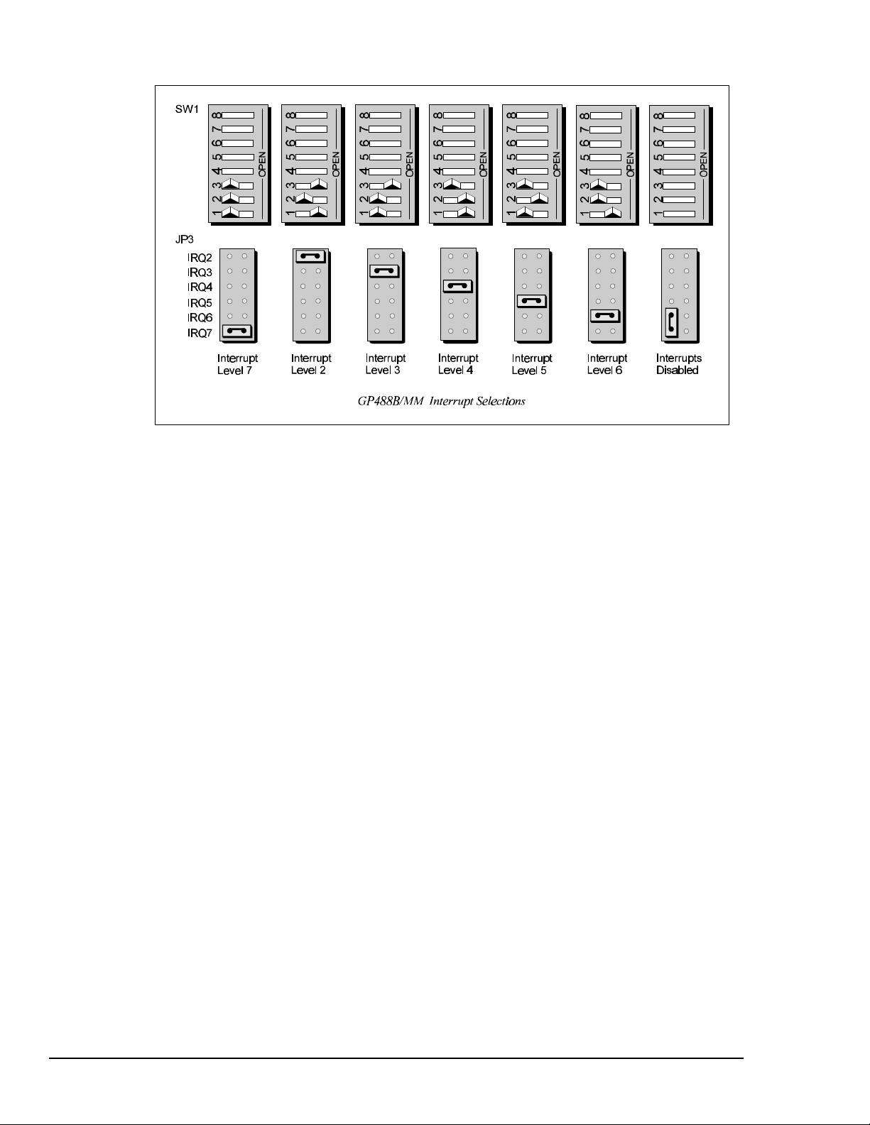
Step 3: Configuring the GP488B/MM Interface Interrupt (IRQ)
1. The factory default Interrupt (IRQ) is 7. If this creates a conflict, reset SW1 microswitches 1, 2,
and 3, and jumper JP3 according to the figure. The switch and jumper settings must both indicate
the same interrupt level for correct operation with interrupts.
2. If reset, record the new Interrupt (IRQ) being used.
The GP488B/MM Revision B interface board may be set to interrupt the PC on the occurrence of
certain hardware conditions. The level of the interrupt generated is set by JP3. The GP488B/MM
interface board adheres to the “AT-style” interrupt sharing conventions. When an interrupt occurs, the
interrupting device must be reset by writing to I/O address 02FX, where X is the interrupt level (from 0
to 7). This interrupt response level is set by switches 1, 2, and 3 of SW1 which must be set to
correspond to the JP3 interrupt level setting.
36 Personal488/MM (with GP488B/MM) Personal488 User's Manual For Windows95 and Windows NT
Page 43

Step 4: Configuring the GP488B/MM Interface DMA Channel
1. The factory default DMA channel is 1. If this creates a conflict, reset jumper JP2 according to the
figure.
2. If reset, record the new DMA channel being used.
Direct Memory Access (DMA) is a high-speed method of transferring data from or to a peripheral, such
as a digitizing oscilloscope, to or from the PC’s memory. The factory default selection is DMA
Channel 1. Notice that jumper JP2 is used to select the DMA channel.
Check your computer documentation to ensure the selected DMA channel is not being used by another
device. The GP488B/MM board has circuitry which allows for more than one GP488B/MM board to
share the same channel. Most computers use DMA Channel 2 for floppy disk drives, making that
channel unavailable.
Personal488 User's Manual For Windows 95 and Windows NT Personal488/MM (with GP488B/MM) 37
Page 44

Installing the New Hardware & Hardware Drivers
Unlike typical IEEE 488 interface boards which are installed into expansion slots inside the PC’s
system unit, the GP488B/MM Mini-Module interface board is installed into the Ampro PC/104 board
by using its “stack-through” connector.
For technical assistance, see chapter Troubleshooting on page 119 in this manual, or the
troubleshooting section in your PC’s manual. If you are still not sure of the problem, contact the dealer
or manufacturer of your interface board or PC.
Step 1: Installing the GP488B/MM Interface Board onto the PC/104 Board
1. Turn OFF the power to your computer and any other connected peripheral devices. Follow the
precautions for static electricity discharge.
• Touch a large grounded metal surface to discharge any static electricity build up in your body.
• Avoid any contact with internal parts. Handle cards only by their edges.
• Disconnect the AC power before removing the cover.
2. Unplug all power cords and cables that may interfere from the back of the computer.
3. Remove your computer's cover by removing its mounting screws with a screwdriver. Slide the
cover OFF. If necessary, refer to your PC's manual.
4. Locate the bus expansion connector on the Ampro PC/104 board. This connector is a 64-socket
header consisting of two rows of 32 sockets. Then locate the “stack-through” bus expansion
connector on your GP488B/MM. This connector has a similar 64-socket header on the front with
64 pins extending from the back of the header.
5. Lining up the screw and/or spacer locations, insert the 64-pin connector of the GP488B/MM
carefully into the 64-socket header on the Ampro PC/104 board.
6. With the board firmly in place, secure the GP488B/MM using the appropriate screws and/or
spacers.
7. Replace the computer's cover and screws. Then reconnect all power cords and cables to the back of
the computer. If available, connect your external data acquisition instrument to the IEEE 488 port
connector on the interface.
8. Turn on your PC.
At this point, the hardware installation is complete. Continue to Step 2.
Step 2: Detecting the GP488B/MM Interface Board in "Add New Hardware"
1. After installing the IEEE 488 controller interface, turn on your computer. Windows will detect the
new hardware and prompt for a Manufacturer’s Disk.
2. Insert the disk labeled "Driver488 Driver Disk, 1 of 1" into the floppy disk drive. Click OK.
3. The hardware will now be recognized by Windows; the "Add New Hardware Wizard" will assign
the available I/O base address, IRQ (Interrupt), and DMA channel, which were configured earlier.
(Additional GP488B/MM interfaces may use the same IRQ and DMA values.)
Continue as prompted to load the interface driver, but DO NOT restart Windows. Select No to
NOT shut down and go directly to the Device Manager to verify the presence of the new hardware
device.
At this point, the hardware detection is complete. Continue to Step 3.
38 Personal488/MM (with GP488B/MM) Personal488 User's Manual For Windows95 and Windows NT
Page 45

Step 3: Verifying the GP488B/MM Interface Installation & Driver488 Software Settings
1. To confirm proper installation, open the Control Panel window from the Start > Settings menu,
click on the System icon, and select the Device Manager tab. Look for a device type named
"IEEE488.2 Controllers" and below it, verify the presence of the new hardware device.
2. During Driver488 installation, a new Control Panel applet titled "IEEE 488" was installed under the
Control Panel with default settings selected.
To verify or configure the Driver488 software settings for your IEEE 488 interface(s) and IEEE 488
external device(s), see chapter Driver488/W95 & Driver488/WNT on page 41.
• When the I/O base address, IRQ (Interrupt), and DMA channel settings match the jumpered
board, select OK and restart Windows below.
• If any of these settings do not match, manually reset each value. When all of the settings are
correct, select OK and restart Windows below.
3. Restart Windows and once again verify the hardware installation and Driver488 configuration in
Device Manager.
At this point, the hardware and driver verification is complete. Continue to Step 4.
Step 4: Installing the GP488B Interface Software Support Files
1. Insert the disk titled "IEEE 488 Software Installation Disk, 1 of 2" into the floppy disk drive.
2. To install, you can do one of the following:
• Select Run from the Start Menu, type in A:\SETUP.EXE, then click OK.
• Go to My Computer or Windows Explorer, double-click on the Floppy Drive icon, then double-
click on the Setup icon.
• Or go to the Control Panel from the Start > Settings menu, double-click on the Add/Remove
Programs icon, then click the Install button.
3. The Installation program will step you through various options on installing these software support
files.
Note: These files are NOT required to get the hardware to work properly, but it is recommended
if any software development is desired or Help files are needed.
4. Any or all of the installed software support files may be removed by going to the Control Panel
from the Start > Settings menu, double-clicking on the Add/Remove Programs icon, then selecting
"Personal IEEE 488 v 2.0", and clicking the Add/Remove… button.
At this point, the installation of software support files is complete.
Personal488 User's Manual For Windows 95 and Windows NT Personal488/MM (with GP488B/MM) 39
Page 46
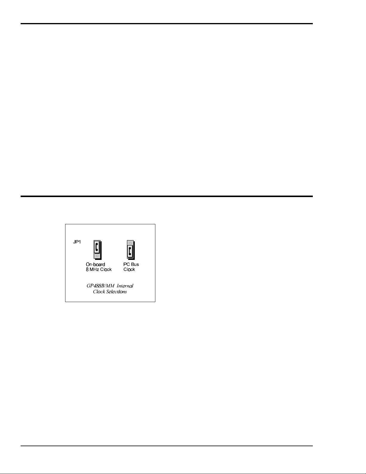
Updating the Existing Hardware Drivers
Updating the GP488B/MM Interface Hardware Drivers
1. Insert the disk titled "Driver488 Driver Disk, 1 of 1" into the floppy disk drive.
2. Open the Control Panel window from the Start > Settings menu, click on the System icon, and
select the Device Manager tab. Look for a device type named "IEEE488.2 Controllers".
3. Highlight the device you want to update under "IEEE488.2 Controllers".
4. Click on the Properties button. Click on the Driver tab.
5. Highlight the driver file named "C:\Windows\System\___488.vxd". (For example,
"…\vpci488.vxd".)
6. Click on the Change Driver button.
7. Select the model that you are updating. Click OK.
Note: DO NOT select the Have Disk... button.
8. Windows will return you to the Driver tab. Click OK. The hardware drivers will now be updated
from the Driver Disk.
9. Windows will prompt you if you wish to restart the system. Select Yes. Otherwise the hardware
will continue to use the outdated drivers until the next time the system is restarted.
Configuring Other Hardware Settings
Configuring the GP488B/MM Interface Internal Clock
The IEEE 488 bus interface circuitry requires a master clock. This clock is normally connected to an
on-board 8 MHz clock oscillator. However, some compatible IEEE 488 interface boards connect this
clock to the PC’s own clock signal. Using the PC clock to drive the IEEE 488 bus clock is not
recommended because the PC clock frequency depends on the model of computer. A standard PC has
a 4.77 MHz clock, while an AT might have a 6 MHz or 8 MHz clock. Other manufacturers’ computers
may have almost any frequency clock. If you are using a software package designed for an interface
board (that derived its clock from the PC clock) and you need to do the same to use GP488B/MM with
that particular software, the clock source can be changed. However, the clock frequency must never be
greater than 8 MHz, and clock frequency must be correctly entered in the Driver488 software.
40 Personal488/MM (with GP488B/MM) Personal488 User's Manual For Windows95 and Windows NT
Page 47

Driver488/W95 & Driver488/WNT 8
Introduction……41
Differences from 16-Bit Driver488 Software……41
Programming Support……42
16-Bit Driver488/W95 Compatibility Layer……42
Configuration Utility……42
Configuring the Driver488 Software Settings……43
Introduction
Differences from 16-Bit Driver488 Software
The following list provides the general differences between 32-bit Driver488 software (for Windows
95 and Windows NT), and 16-bit Driver488 software (for Windows 3.X). With the 32-bit driver:
• There is no RS-232 serial support.
• The function Hello now returns two lines of ID: One for the Dynamic Link Library (DLL) and
one for the device driver.
• The library function prototypes have changed to reflect standard Windows types.
• The include file has been renamed to: IOTIEEE.H
The following outline provides the specific differences in API command functions, between 32-bit
Driver488 software, and 16-bit Driver488 software. With the 32-bit driver:
Obsolete Functions
The parameters that these functions set are now set by a provided Windows Control Panel
configuration utility:
• ClockFrequency
• DmaChannel
• IntLevel
• IOAddress
• LightPen
• SysController
New Functions
These are functions not previously supported:
• MakeNewDevice
• OnEventVDM (Console mode applications)
• TermQuery
• TimeOutQuery
Enhanced Functions
These are updated functions:
• ControlLine
• Hello
• KeepDevice
Personal488 User's Manual For Windows 95 and Windows NT Driver488/W95 & Driver488/WNT 41
Page 48

Programming Support
Driver488/W95 and Driver488/WNT both provide language interfaces for Microsoft C, Visual Basic,
Borland C++, and Borland Delphi. These 32-bit drivers make IEEE events in your C or C++
applications conform to Windows’ standard event handling scheme, passing IEEE events such as bus
errors and SRQs to Windows as standard messages. This assures consistent handling of IEEE and user
events.
When building your programs with Microsoft C to use the IEEE 488 interface, be sure to “include” the
IOTIEEE.H file in your source and be sure to link the IOTSLPIB.LIB export library with your
program.
16-Bit Driver488/W95 Compatibility Layer
Unlike Driver488/WNT, Driver488/W95 supports backward compatibility for applications written in
the 16-bit environment of the Driver488/W31 (formerly named Driver488/WIN) product. Support is
provided through a Dynamic Link Library, DRVR488.DLL, and various language-specific header files
which will allow the recompilation of 16-bit applications.
Differences from 16-Bit Driver488 Software
Although Driver488/W95 supports asynchronous Enter and Output operations, its 16-bit
compatibility layer for Windows 3.X does not support asynchronous Enter and Output operations.
The asynchronous flag is ignored and the Enter or Output operation is treated as a synchronous
operation.
The OnEvent feature is not supported by the Windows 3.X compatibility layer. A call to OnEvent
will return an error and the error value will be set to an obsolete value.
Existing 16-bit programs will run with Driver488/W95 without any re-compilation or re-linking. Since
the compatibility layer DLL has the same name as the Windows 3.X driver DLL, existing programs
written for Driver488/W31 (or Driver488/WIN) will automatically link to the compatibility layer and
through it, link to Driver488/W95.
To use the 16-bit compatibility, the DRVR488.DLL must be copied into your system directory or to the
location of a previously installed 16-bit DRVR488.DLL for Windows 3.X.
Configuration Utility
The configuration utility is accessed from the Windows Control Panel. This utility allows you to
configure Driver488/W95 or Driver488/WNT, as well as any user-specified IEEE 488 External
Devices.
Interfaces
The minimum requirement for configuring your system is to make certain that your IEEE 488.2
interface board is selected under Device Type. The default settings in all of the other fields match those
of the interface as shipped from the factory. If you are unsure of a setting, it is recommended that you
leave it as it is.
External Devices
Each external device requires a handle or “call” to communicate with Driver488. An external device
handle is a means of maintaining a record of its three configurable items:
• IEEE 488 bus address
• IEEE 488 bus terminators
• Time out period.
Any communication with the external device uses these three items. All external devices have either a
default value or a user-supplied value for the different fields. All of the fields can be changed by
Driver488 commands during program execution.
42 Driver488/W95 & Driver488/WNT Personal488 User's Manual For Windows95 and Windows NT
Page 49

Configuring the Driver488 Software Settings
Note:
The following configuration information is software oriented. It is assumed that you have
already successfully performed the necessary hardware and hardware driver installations, as
provided in the appropriate hardware chapter of this manual.
Step 1: Opening the Configuration Utility
1. Open the Windows Control Panel from the Start > Settings menu.
2. Double-click on the IEEE 488 Driver icon. The IEEE 488 Interface Properties dialog box will
appear.
3. Select the Interfaces and Devices tab to display a list of the four available IEEE 488 interfaces:
IEEE0, IEEE1, IEEE2, and IEEE3.
4. At this point, you have the option of configuring an interface or configuring an external device.
Step 2: Configuring the IEEE 488 Interface
Interface Dialog Box
IEEE 488 Interface Properties Dialog Box
Interfaces and Devices Tab
1. From the Interfaces and Devices tab of the IEEE 488 Interface Properties dialog box, click on the
appropriate interface name to highlight the interface to be configured.
2. Select the Properties button. The Interface dialog box will appear.
3. Fill in the appropriate configuration parameters.
• Driver: This field is automatically assigned. It shows the interface that has been chosen for
configuration.
• Interface Name: This field is a descriptive instrument name which is automatically assigned
by the driver. It is a duplication of the driver interface.
• Primary Address: This field is the setting for the IEEE bus address of the board. It will be
checked against all the instruments on the bus for conflicts. It must be a valid IEEE bus
address between 0 and 30. The Secondary Address field is not supported.
• Timeout (ms): The time out period is the amount of time that data transfers wait before
assuming that the device does not transfer data. If the time out period elapses while waiting to
transfer data, an error signal occurs. This field is the default timeout for any bus request or
action, measured in milliseconds. If no timeout is desired, the value may be set to zero.
• Port Address: This field is the I/O base address.
Personal488 User's Manual For Windows 95 and Windows NT Driver488/W95 & Driver488/WNT 43
Page 50

• Interrupt: This field is the hardware interrupt level (IRQ). IRQ is not an option; it is a
requirement. Valid settings for the interrupt levels of specific boards, are provided in the chart.
• DMA: A DMA channel can be specified for use. If DMA is to be used, select a channel as per
the hardware setting. If no DMA is to be used, select NONE. Valid settings for the DMA
channels of specific boards, are provided in the chart.
Board Interrupt Levels DMA Channels
GP488B levels 2-7 1, 2, 3 or none
GP488B/MM levels 2-7 1, 2, 3 or none
AT488 levels 3-7, 9-12, or 14-15 1, 2, 3, 5, 6, 7 or none
• System Controller (Check Box): The IEEE 488 interface board is configured as a System
Controller or Peripheral by clicking on the System Controller toggle check box. The interface
board is configured as a System Controller if a “check mark” is present in the check box. The
System Controller has ultimate control of the IEEE 488 bus and therefore has the ability of
asserting the Interface Clear (IFC) and Remote Enable (REN) signals. Each IEEE 488 bus can
have only one System Controller. If the board is configured as a Peripheral, it can obtain
control of the IEEE 488 bus from the Active Controller. Once control status is achieved, the
peripheral board may take control of the bus and carry out its assignments. Upon completion
of its tasks, control will be relinquished to the System Controller or another computer.
• Input & Output Terminators (Bus Termination): The IEEE488 bus terminators specify the
characters and/or EOI signal that is to be appended to data that is sent to the external device, or
mark the end of data that is received from the external device.
Step 3: Configuring the IEEE 488 External Device
Device Dialog Box
IEEE 488 Interface Properties Dialog Box
Interfaces and Devices Tab
44 Driver488/W95 & Driver488/WNT Personal488 User's Manual For Windows95 and Windows NT
Page 51

1. From the Interfaces and Devices tab of the IEEE 488 Interface Properties dialog box, click on the
“+” node symbol located just to the left of the desired interface. A list of external devices
associated with that interface will display.
2. At this point, you have the option of using one of the provided device names (such as Dev1) or
creating a new one.
• To use one of the provided device names, click to highlight the desired external device, and
select the Properties button. The Device dialog box will appear.
• Otherwise, to create a new user-specified device name, click on the Add Device button. A
Device dialog box will appear much like the one shown above. The only difference is that all
of the configuration fields are blank and must be user-specified. Provide a Name for the
external device.
3. Fill in the appropriate configuration parameters.
• Name: This field specifies the type of device represented by the IEEE device name selected.
External Device names are user-defined names which are used to convey the configuration
information about each device from the initialization file to the application program. External
device names consist of 1 to 32 characters, and the first character must be a letter. The
remaining characters may be letters, numbers, or underscores (“_”). External device names are
case insensitive; upper and lower case letters are equivalent. ADC is the same device as adc.
Each external device must have a name to identify its configuration. The name can then be
used to obtain a handle to that device which will be used by all of the Driver488 commands.
• Primary & Secondary Addresses: These fields specify the IEEE 488 bus primary and
secondary addresses of the external device. They will be checked against all the instruments on
the bus for conflicts. The IEEE488 bus primary address ranges from 0 to 30, and the optional
secondary address ranges from 0 to 31.
• Timeout (ms): The time out period is the amount of time that data transfers wait before
assuming that the device does not transfer data. If the time out period elapses while waiting to
transfer data, an error signal occurs. This field is the default timeout for any bus request or
action, measured in milliseconds. If no timeout is desired, the value may be set to zero.
• Input & Output Terminators: The IEEE 488 bus terminators specify the characters and/or EOI
signal that is to be appended to data that is sent to the external device, or mark the end of data
that is received from the external device.
Because secondary addresses and bus terminators are specified by each handle, it may be useful to
have several different external devices defined for a single IEEE 488 bus device. For example,
separate device handles would be used to communicate with different secondary addresses within a
device. Also, different device handles might be used for communication of command and status
strings (terminated by carriage return CR, line feed LF), and for communication of binary data
(terminated by EOI).
Personal488 User's Manual For Windows 95 and Windows NT Driver488/W95 & Driver488/WNT 45
Page 52

- Notes
46 Driver488/W95 & Driver488/WNT Personal488 User's Manual For Windows95 and Windows NT
Page 53

API Command Reference 9
Introduction……47
Abort……48
Arm……49
AutoRemote……50
Buffered……51
BusAddress……52
CheckListener……53
Clear……54
ClearList……55
Close……56
ControlLine……57
DigArm……58
DigArmSetup……59
DigRead……60
DigSetup……61
DigWrite……62
Disarm……63
EnterX……64
Error……66
FindListener……67
Finish……68
GetError……69
GetErrorList……70
Hello……71
KeepDevice……72
Listen……73
Local……74
LocalList……75
Lol……76
MakeDevice……77
MakeNewDevice……78
MyListenAddr……79
MyTalkAddr……80
OnDigEvent……81
OnDigEventVDM……82
OnEvent……83
OnEventVDM……84
OpenName……86
OutputX……87
PassControl……89
PPoll……90
PPollConfig……91
PPollDisable……92
PPollDisableList……93
PPollUnconfig……94
Remote……95
RemoteList……96
RemoveDevice……97
Request……98
Reset……99
Resume……100
SendCmd……101
SendData……102
SendEoi……103
SPoll……104
SPollList……105
Status……106
Stop……108
Talk……109
Term……110
TermQuery……111
TimeOut……112
TimeOutQuery……113
Trigger……114
TriggerList……115
UnListen……116
UnTalk……117
Wait……118
Introduction
This chapter contains the API command reference for Driver488/W95 and Driver488/WNT, using the
C language. The following 67 commands are presented in alphabetical order for ease of use.
Personal488 User's Manual For Windows 95 and Windows NT API Command Reference 47
Page 54
Abort
Syntax
Returns
Mode
Bus States
Example
See Also
INT WINAPI Abort(DevHandleT devHandle);
devHandle refers to either an IEEE 488 hardware interface or an external device. If
devHandle refers to an external device, the Abort command will act on the
hardware interface to which the external device is attached.
-1 if error
SC or *SC•CA
IFC, *IFC (if SC)
ATN•MTA (if *SC••CA)
errorflag = Abort(ieee);
MyTalkAddr, Talk, UnTalk
As the System Controller (SC), whether Driver488 is the Active Controller or not, the Abort command
causes the Interface Clear (IFC) bus management line to be asserted for at least 500 microseconds. By
asserting IFC, Driver488 regains control of the bus even if one of the devices has locked it up during a
data transfer. Asserting IFC also makes Driver488 the Active Controller. If a Non System Controller
was the Active Controller, it is forced to relinquish control to Driver488. Abort forces all IEEE 488
device interfaces into a quiescent state.
If Driver488 is a Non System Controller in the Active Controller state (*SC••CA), it asserts Attention
(ATN), which stops any bus transactions, and then sends its My Talk Address (MTA) to “Untalk” any
other Talkers on the bus. It does not (and cannot) assert IFC.
48 API Command Reference Personal488 User's Manual For Windows95 and Windows NT
Page 55

Arm
Syntax
Returns
Mode
Bus States
Example
See Also
INT WINAPI Arm(DevHandleT devHandle, ArmCondT condition);
devHandle refers to either an IEEE 488 hardware interface or an external device. If
devHandle refers to an external device, the Arm command acts on the hardware
interface to which the external device is attached.
condition is one of the following: acError, acSRQ, acPeripheral,
acController, acTrigger, acClear, acTalk, acListen, acIdle,
acByteIn, acByteOut, or acChange.
-1 if DevHandleT is an illegal device or interface
otherwise, the current state of the event trigger flag
Any
None
errorflag = Arm(ieee, acSRQ|acTrigger|acChange);
Disarm, OnEvent
The Arm command allows Driver488 to signal to the user-specified function when one or more of the
specified conditions occurs. Arm sets a flag for each implementation of the conditions which are userindicated. Arm conditions may be combined using the bitwise OR operator.
The following Arm conditions are supported:
Condition Description
acSRQ The Service Request bus line is asserted.
acPeripheral An addressed status change has occurred and the interface is a Peripheral.
acController An addressed status change has occurred and the interface is an Active Controller.
acTrigger The interface has received a device Trigger command.
acClear The interface has received a device Clear command.
acTalk An addressed status change has occurred and the interface is a Talker.
acListen An addressed status change has occurred and the interface is a Listener.
acIdle An addressed status change has occurred and the interface is neither Talker nor Listener.
acByteIn The interface has received a data byte.
acByteOut The interface has been configured to output a data byte.
acError A Driver488 error has occurred.
acChange The interface has changed its addressed status. Its Controller/Peripheral or
Talker/Listener/Idle states of the interface have changed.
Personal488 User's Manual For Windows 95 and Windows NT API Command Reference 49
Page 56
AutoRemote
Syntax
Returns
Mode
Bus States
Example
See Also
INT WINAPI AutoRemote(DevHandleT devHandle, BOOL flag);
devHandle refers to either an IEEE 488 hardware interface or an external device. If
devHandle refers to an external device, the AutoRemote command acts on the
hardware interface to which the external device is attached.
flag may be either OFF or ON
-1 if DevHandleT is an illegal device or interface
otherwise, the previous state is returned
SC
None
errorcode = AutoRemote(ieee,ON);
Local, Remote, EnterX, OutputX
The AutoRemote command enables or disables the automatic assertion of the Remote Enable (REN)
line by Output. When AutoRemote is enabled, Output automatically asserts REN before transferring
any data. When AutoRemote is disabled, there is no change to the REN line. AutoRemote is on by
default.
50 API Command Reference Personal488 User's Manual For Windows95 and Windows NT
Page 57

Buffered
Driver488/W95 only
Syntax
Returns
Mode
Bus States
Example
See Also
The Buffered command returns the number of characters transferred by the latest Enter, Output,
SendData, or SendEoi command. If an asynchronous transfer is in progress, the result is the number
of characters that have been transferred at the moment the command is issued. This command is most
often used after a counted Enter, EnterN, EnterNMore, etc., to determine if the full number of
characters was received, or if the transfer terminated upon detection of term. It is also used to find out
how many characters have currently been sent during an asynchronous DMA transfer.
LONG WINAPI Buffered(DevHandleT devHandle);
devHandle refers to either an IEEE 488 hardware interface or an external device. If
devHandle refers to an external device, the Buffered command acts on the
hardware interface to which the external device is attached.
-1 if error
otherwise long integer from 0 to 1,048,575(2
Any
None
result = Buffered(ieee);
printf(“%ld bytes were received.”,result);
EnterX, OutputX
20
-1)
Personal488 User's Manual For Windows 95 and Windows NT API Command Reference 51
Page 58

BusAddress
Syntax
Returns
Mode
Bus States
Example
See Also
INT WINAPI BusAddress (DevHandleT devHandle, BYTE primary,
BYTE secondary);
devHandle refers to either an IEEE 488 hardware interface or an external device.
primary is the IEEE 488 bus primary address of the specified device.
secondary is the IEEE 488 bus secondary address of the specified device. If the
specified device is an IEEE 488 hardware interface, this value must be -1 since there
are no secondary addresses for the IEEE 488 hardware interface. For no secondary
address, a -1 must be specified.
-1 if error
Any
None
errorcode = BusAddress(dmm,14,0);
MakeDevice
The BusAddress command sets the IEEE 488 bus address of the IEEE 488 hardware interface or an
external device. Every IEEE 488 bus device has an address that must be unique within any single
IEEE 488 bus system. The default IEEE 488 bus address for Driver488 is 21, but this may be changed
if it conflicts with some other device.
52 API Command Reference Personal488 User's Manual For Windows95 and Windows NT
Page 59

CheckListener
Syntax
Returns
Mode
Bus States
Example
See Also
INT WINAPI CheckListener(DevHandleT devHandle, BYTE primary,
BYTE secondary);
devHandle refers to either an IEEE 488 hardware interface or an external device. If
devHandle refers to an external device, the CheckListener command acts on
the hardware interface to which the external device is attached.
primary is the primary bus address to check for a Listener (00 to 30)
secondary is the secondary bus address to check for a Listener (00 to 31). For no
secondary address, a -1 must be specified
-1 if error
otherwise it returns a 1 if a listener was found at the specified address, or a 0 if a listener
was not found at the specified address.
CA
ATN••UNL, LAG, (check for NDAC asserted)
result = CheckListener(ieee,15,4);
if (result == 1)
{
printf(“Device found at specified address.\n”);
}
if (result == 0)
{
printf(“Device not found at specified address.\n”);
}
FindListener, BusAddress
The CheckListener command checks for the existence of a device on the IEEE 488 bus at the
specified address.
Personal488 User's Manual For Windows 95 and Windows NT API Command Reference 53
Page 60
Clear
Syntax
Returns
Mode
Bus States
Examples
See Also
INT WINAPI Clear(DevHandleT devHandle);
devHandle refers to either an IEEE 488 hardware interface or an external device. If
devHandle refers to a hardware interface, then a Device Clear (DCL) is sent. If
devHandle refers to an external device, a Selected Device Clear (SDC) is sent.
-1 if error
CA
ATN••DCL (all devices)
ATN••UNL, MTA, LAG, SDC (selected device)
errorcode = Clear(ieee); Sends the Device Clear (DCL) command to the
IEEE interface board.
errorcode = Clear(wave); Sends the Selected Device Clear (SDC) command
to the WAVE device.
errorcode = Clear(dmm); Sends the Selected Device Clear (SDC) command
to the DMM device.
Reset, ClearList
The Clear command causes the Device Clear (DCL) bus command to be issued to an interface or a
Selected Device Clear (SDC) command to be issued to an external device. IEEE 488 bus devices that
receive a Device Clear or Selected Device Clear command normally reset to their power-on state.
54 API Command Reference Personal488 User's Manual For Windows95 and Windows NT
Page 61
ClearList
Syntax
INT WINAPI ClearList(DevHandlePT dhList);
dhList is a pointer to a list of device handles that refer to external devices. If a hardware
interface is in the list, DCL is sent instead of SDC.
Returns
Mode
Bus States
-1 if error
CA
ATN••DCL (all devices)
ATN••UNL, MTA, LAG, SDC (selected device)
Example
See Also
deviceList[0] = wave;
deviceList[1] = scope;
deviceList[2] = dmm;
deviceList[3] = NODEVICE;
errorcode = ClearList(deviceList);
Clear, Reset
Sends the Selected Device Clear
(SDC) command to a list of
devices.
The ClearList command causes the Selected Device Clear (SDC) command to be issued to a list of
external devices. IEEE 488 bus devices that receive a Selected Device Clear command normally reset
to their power-on state.
Personal488 User's Manual For Windows 95 and Windows NT API Command Reference 55
Page 62

Close
Syntax
Returns
Mode
Bus States
Example
See Also
INT WINAPI Close(DevHandleT devHandle);
devHandle refers to either an IEEE 488 interface or an external device.
-1 if error
Any
Completion of any pending I/O activities
errorcode = Close(wave);
OpenName, MakeDevice, Wait
The Close command waits for I/O to complete, flushes any buffers associated with the device that is
being closed, and then invalidates the handle associated with the device.
56 API Command Reference Personal488 User's Manual For Windows95 and Windows NT
Page 63

ControlLine
Syntax
INT WINAPI ControlLine(DevHandleT devHandle);
ControlLine returns a bit mapped number.
devHandle refers to the I/O adapter. If devHandle refers to an external device, the
ControlLine command acts on the hardware interface to which the external device
is attached.
Response
Mode
Bus States
Example
-1 if error
otherwise, a bit map of the current state of the IEEE 488 interface. Under 32-bit Driver488
software, serial interfaces are no longer supported.
Any
None
result = ControlLine(ieee);
printf(“The response is %X\n”,result);
See Also
TimeOut
The ControlLine command may be used only on IEEE 488 devices. Under 32-bit Driver488
software, serial interfaces are no longer supported. This command returns the status of the IEEE 488
bus control lines as an 8-bit unsigned value (bits 2 and 1 are reserved for future use), as shown below:
Bit 8 Bit 7 Bit 6 Bit 5 Bit 4 Bit 3 Bit 2 Bit 1
EOI SRQ NRFD NDAC DAV ATN 0 0
Personal488 User's Manual For Windows 95 and Windows NT API Command Reference 57
Page 64

DigArm
AT488pnp and PCI488 only
Syntax
Returns
Mode
Bus States
Example
See Also
The DigArm command arms or disarms the event-generation due to a digital I/O port match condition.
The caller should configure the digital I/O port, the event-callback mechanism, and the match condition
prior to arming the event generation. The following code snippet illustrates this sequence:
DigSetup(devHandle, FALSE, FALSE); // Configure both nibbles for input.
OnDigEventVDM(devHandle, MyFunc, 0); // On event, call function MyFunc.
DigArmSetup(devHandle, 0x0A5); // Trigger when inputs equals 0xA5.
DigArm(devHandle, TRUE); // Enable event generation.
Event generation is automatically disarmed when an event is triggered. The event generation
configuration, however, remains intact, so event generation can be re-armed just by calling DigArm.
The other steps shown in the above code snippet do not need to be repeated unless the event
configuration is to be changed.
INT WINAPI DigArm(DevHandleT devHandle, BOOL bArm);
devHandle refers to an interface handle.
bArm refers to a value that arms or disarms event generation. TRUE = Arm, FALSE =
Disarm.
-1 if neither nibble is set for input, or other error
Any
None
DigArm(devHandle, TRUE);
DigArmSetup, DigSetup, OnDigEvent, OnDigEventVDM
Arms digital input event generation.
Event generation may be disarmed (bArm = FALSE) at any time.
Note:
This function does not configure the digital I/O port for input. The caller must use DigSetup
to configure the port for input before performing arming event generation. If neither nibble is
configured for input the function returns -1 and sets the error code to IOT_BAD_VALUE2.
Note:
Event generation may be re-armed from within the event handler to provide continuous
detection of match condition events. However, this is not guaranteed to catch every event if
the digital input values are rapidly changing.
Note:
Any digital I/O port bits configured for output are treated as “don’t care” bits for the purposes
of event generation. In other words, it is valid to arm an event when only one nibble of the
port is configured for input. In this case, the other nibble is ignored when detecting the match
condition.
58 API Command Reference Personal488 User's Manual For Windows95 and Windows NT
Page 65

DigArmSetup
AT488pnp and PCI488 only
Syntax
Returns
Mode
Bus States
Example
See Also
The DigArmSetup command sets the match condition value. This value will be compared against the
digital I/O port inputs to detect when an event occurs. The event must be armed (via DigArm) for
event notification to take place.
The comparison operation depends on the current digital port configuration. If both nibbles are
configured for input, then the match value is compared to the entire byte value of the digital port. If
only one of the nibbles is configured for input, then the value is compared against just that nibble. If no
nibbles are configured for input, then the match value is ignored. The DigArm function will not allow
event generation to be armed unless at least one of the nibbles is configured for input.
INT WINAPI DigArmSetup(DevHandleT devHandle, BYTE
byMatchValue);
devHandle refers to an interface handle.
byMatchValue refers to a value that is compared against the digital I/O inputs
-1 if error
Any
None
DigArmSetup(devHandle, 0xA5);
DigArm, DigSetup
Sets the match value to 0xA5.
Personal488 User's Manual For Windows 95 and Windows NT API Command Reference 59
Page 66

DigRead
AT488pnp and PCI488 only
Syntax
Returns
Mode
Bus States
Example
See Also
The DigRead command reads the current value of the digital IO port per the input/output configuration
of the port. If the entire port is configured for input, a value between 0 and 255 is returned. If either
the upper or lower nibble is configured for input, and the other for output, a value between 0 and 15 is
returned.
INT WINAPI DigRead(DevHandleT devHandle);
devHandle refers to an interface handle.
-1 if no part of the port is configured for input, or other error
otherwise, integer between 0 and 255 if the entire digital I/O port is configured for input; or
integer between 0 and 15 if only one nibble (either low or high) is configured for input
Any
None
int i = DigRead(devHandle);
DigSetup, DigWrite
Returns the current value of the digital I/O
port per the current configuration.
Note:
This function does not configure the digital I/O port for input. The caller must use DigSetup
to configure the port for input before performing any reads. If neither nibble is configured for
input the function returns -1 and sets the error code to IOT_BAD_VALUE2.
60 API Command Reference Personal488 User's Manual For Windows95 and Windows NT
Page 67

DigSetup
AT488pnp and PCI488 only
Syntax
Returns
Mode
Bus States
Examples
See Also
The DigSetup command configures the digital I/O port for input and output on a per-nibble basis.
Each of the two nibbles can be set for input or output. All combinations are supported. Once
DigSetup is called, the configuration of the digital I/O port does not change until the next call to
DigSetup. The port may be read and written many times without affecting the port setup.
INT WINAPI DigSetup(DevHandleT devHandle, BOOL bLowOut, BOOL
bHighOut);
devHandle refers to an interface handle.
bLowOut refers to the lower nibble setup. TRUE = output, FALSE = input.
bHighOut refers to the upper nibble setup. TRUE = output, FALSE = input.
-1 if error
Any
None
DigSetup(devHandle, TRUE , TRUE);
DigSetup(devHandle, FALSE, TRUE); Lower 4 bits input, upper 4 output.
DigSetup(devHandle, TRUE , FALSE); Lower 4 bits output, upper 4 input.
DigSetup(devHandle, FALSE, FALSE); All 8 bits input.
DigRead, DigWrite
All 8 bits output.
Note:
The digital I/O port must be configured every time the driver is opened. The configuration is
not stored between sessions.
Personal488 User's Manual For Windows 95 and Windows NT API Command Reference 61
Page 68
DigWrite
AT488pnp and PCI488 only
Syntax
Returns
Mode
Bus States
Example
See Also
The DigWrite command writes the given value to the digital I/O port per the input/output
configuration of the port. If the entire port is configured for output, then the data value with a range
from 0 to 255 is written to the port. If either the upper or lower nibble is configured for input, and the
other for output, then the data value is truncated to the range from 0 to 15 and it is written to the
appropriate nibble per the current configuration.
INT WINAPI DigWrite(DevHandleT devHandle, BYTE byDigData);
devHandle refers to an interface handle.
byDigData refers to a value to write to the digital output port, where the integer range is
between 0 and 255 if the entire digital I/O port is configured for output, or between 0
and 15 if only one nibble (either low or high) is configured for output.
-1 if no part of the digital I/O port is configured for output.
Any
None
DigRead(devHandle, 0x0A);
DigSetup, DigRead
Writes the given value to the digital I/O port per
the current configuration.
Note:
Note:
This function does not configure the digital I/O port for output. The caller must use
DigSetup to configure the port before performing any reads or writes. If neither nibble is
configured for output the function returns -1 and sets the error code to IOT_BAD_VALUE2.
Outputs do not persist after an interface is closed. At that time, all digital I/O lines are
configured for input.
62 API Command Reference Personal488 User's Manual For Windows95 and Windows NT
Page 69

Disarm
Syntax
Returns
Mode
Bus States
Examples
See Also
INT WINAPI Disarm(DevHandleT devHandle, ArmCondT condition);
devHandle refers to either an IEEE 488 interface or an external device. If devHandle
refers to an external device, then the Disarm command acts on the hardware interface
to which the external device is attached.
condition specifies which of the conditions are no longer to be monitored. If condition is
0, then all conditions are Disarmed.
-1 if error
otherwise, the current bit map of the event condition mask.
Any
None
errorcode=Disarm(ieee,acTalk|acListen|acChange);
errorcode=Disarm(ieee,0);
Arm, OnEvent
The Disarm command prevents Driver488 from invoking an event handler and interrupting the PC,
even when the specified condition occurs. Your program can still check for the condition by using the
Status command. If the Disarm command is invoked without specifying any conditions, then all
conditions are disabled. The Arm command may be used to re-enable interrupt detection.
Personal488 User's Manual For Windows 95 and Windows NT API Command Reference 63
Page 70

EnterX
Syntax
Returns
Mode
Bus States
Example
See Also
LONG WINAPI EnterX(DevHandleT devHandle, LPBYTE data,DWORD
count,BOOL forceAddr,TermT*term,BOOL async,LPDWORD
compStat);
devHandle refers to either an IEEE 488 interface or an external device.
data is a pointer to the buffer into which the data is read.
count is the number of characters to read.
forceAddr is used to specify whether the addressing control bytes are to be issued for
each EnterX command.
term is a pointer to a terminator structure that is used to set up the input terminators. If
term is set to 0, the default terminator is used.
async is a flag that allows asynchronous data transfer. Note that this asynchronous flag is
ignored in Driver488/WNT.
compStat is a pointer to an integer containing completion status information.
-1 if error
otherwise, the actual count of bytes transferred. The memory buffer pointed to by the data
parameter is filled in with the information read from the device. Note that the actual
count does not include terminating characters if term characters are specified by the
term in function. In addition, term characters are not returned but are discarded.
CA
With interface handle: *ATN, data
With external device handle: ATN••UNL, MLA, TAG, *ATN, data
term.EOI = TRUE;
term.nChar = 1;
term.EightBits = TRUE;
term.termChar[0] = ‘\r’;
bytecount=EnterX(timer,data,1024,0,&term,1,&stat);
OutputX, Term, Buffered
Note:
The asynchronous flag async is ignored in Driver488/WNT.
The EnterX command reads data from the I/O adapter. If an external device is specified, then
Driver488 is addressed to Listen, and that device is addressed to Talk. If an interface is specified, then
Driver488 must already be configured to receive data and the external device must be configured to
Talk, either as a result of an immediately preceding EnterX command or as a result of one of the Send
commands. EnterX terminates reception on either the specified count of bytes transferred, or the
specified or default terminator being detected. Terminator characters, if any, are stripped from the
received data before the EnterX command returns to the calling application.
The forceAddr flag is used to specify whether the addressing control bytes are to be issued for each
EnterX command. If the device handle refers to an I/O adapter, then forceAddr has no effect and
command bytes are not sent. For an external device, if forceAddr is TRUE then Driver488 always
sends the UNL, MLA, and TAG command bytes. If forceAddr is FALSE, then Driver488 compares the
current device with the previous device that used that interface adapter board for an EnterX command.
If they are the same, then no command bytes are sent. If they are different, then EnterX acts as if the
forceAddr flag were TRUE and sends the command bytes. The forceAddr flag is usually set TRUE
for the first transfer of data from a device, and then set FALSE for additional transfers from the same
block of data from that device.
Additional Enter Functions
Driver488 provides additional Enter routines that are short-form versions of the EnterX function.
The following Enter functions are already defined in your header file.
64 API Command Reference Personal488 User's Manual For Windows95 and Windows NT
Page 71
Enter
Syntax
Remarks
The Enter function passes the device handle and a pointer to the data buffer to the EnterX function.
It determines the size of the data buffer that you provided, and passes that value as the count
parameter. It specifies forceAddr is TRUE, causing Driver488 to re-address the device. The default
terminators are chosen by specifying a 0 as the term parameter. Asynchronous transfer is turned off by
sending 0 for the async parameter, and the completion status value is ignored by sending 0 for the
compStat parameter.
LONG WINAPI Enter(DevHandleT devHandle, LPBYTE data)
Enter is equivalent to the following call to EnterX:
EnterX(devHandle,data,sizeof(data),1,0L,0,0L);
EnterN
Syntax
Remarks
The EnterN function passes the device handle, the pointer to the data buffer, and the size of the data
buffer to the EnterX function. It specifies forceAddr is TRUE, causing Driver488 to re-address the
device. The default terminators are chosen by specifying a 0 pointer as the term parameter.
Asynchronous transfer is turned off by sending 0 for the async parameter, and the completion status
value is ignored by sending 0 for the compStat parameter.
LONG WINAPI EnterN(DevHandleT devHandle,LPBYTE data,int
count)
EnterN is equivalent to the following call to EnterX:
EnterX(devHandle,data,count,1,0L,0,0L);
EnterMore
Syntax
Remarks
The EnterMore function passes the device handle and the pointer to the data buffer to the EnterX
function. It determines the size of the data buffer that you provided, and passes that value as the count
parameter. It specifies forceAddr is FALSE, therefore Driver488 does not address the device if it is
the same device as previously used. The default terminators are chosen by specifying a 0 as the term
parameter. Asynchronous transfer is turned off by sending 0 for the async parameter, and the
completion status value is ignored by sending 0 for the compStat parameter.
LONG WINAPI EnterMore(DevHandleT devHandle,LPBYTE data)
EnterMore is equivalent to the following call to EnterX:
EnterX(devHandle,data,sizeof(data),0,0L,0,0L);
EnterNMore
Syntax
Remarks
The EnterNMore function passes the device handle, the pointer to the data buffer, and the size of the
data buffer to the EnterX function. It specifies forceAddr is FALSE; therefore, Driver488 does not
address the device if it is the same device as previously used. The default terminators are chosen by
specifying a 0 as the term parameter. Asynchronous transfer is turned off by sending 0 for the async
parameter, and the completion status value is ignored by sending 0 for the compStat parameter.
LONG WINAPI EnterNMore(DevHandleT devHandle,LPBYTE data,int
count);
EnterNMore is equivalent to the following call to EnterX:
EnterX(devHandle,data,count,0,0L,0,0L);
Personal488 User's Manual For Windows 95 and Windows NT API Command Reference 65
Page 72

Error
Syntax
Returns
Mode
Bus States
Example
See Also
INT WINAPI Error(DevHandleT devHandle, BOOL display);
devHandle refers to either an IEEE 488 interface or an external device.
display indicates whether the error message display should be ON or OFF.
-1 if error
Any
None
errorcode = Error(ieee, OFF);
OnEvent, GetError, GetErrorList, Status
The Error command enables or disables automatic on-screen display of Driver488 error messages.
Specifying ON enables the error message display, while specifying OFF disables the error message
display. Error ON is the default condition.
66 API Command Reference Personal488 User's Manual For Windows95 and Windows NT
Page 73

FindListeners
Syntax
Returns
Mode
Bus States
Example
See Also
INT WINAPI FindListeners(DevHandleT devHandle, BYTE primary,
LPWORD listener, DWORD limit);
devHandle refers to either an IEEE 488 interface or an external device. If devHandle
refers to an external device, then the FindListeners command acts on the
hardware interface to which the external device is attached.
primary is the primary IEEE 488 bus address to check.
listener is a pointer to a list that contains all Listeners found on the specified interface
board. You must allocate enough memory to accommodate all of the possible Listeners
up to the limit that he specified.
limit is the maximum number of Listeners to be entered into the Listener list.
-1 if error
otherwise, the number of Listeners found on the interface
Any
ATN••MTA, UNL, LAG
WORD listeners[5];
errorcode = FindListeners(ieee,10,listeners,5);
CheckListener, BusAddress, Status
The FindListeners command finds all of the devices configured to Listen at the specified primary
address on the IEEE 488 bus. The command first identifies the primary address to check and returns
the number of Listeners found and their addresses. Then, it fills the user-supplied array with the
addresses of the Listeners found. The number of Listeners found is the value returned by the function.
The returned values include the secondary address in the upper byte, and the primary address in the
lower byte. If there is no secondary address, then the upper byte is set to 255; hence, a device with
only a primary address of 16 and no secondary address is represented as 0xFF10 or -240 decimal.
Personal488 User's Manual For Windows 95 and Windows NT API Command Reference 67
Page 74
Finish
Driver488/W95 only
Syntax
Returns
Mode
Bus States
Example
See Also
The Finish command asserts Attention (ATN) and releases any pending holdoffs after a Resume
function is called with the monitor flag set.
INT WINAPI Finish(DevHandleT devHandle);
devHandle refers to either an IEEE 488 interface or an external device. If devHandle
refers to an external device, the Finish command acts on the hardware interface to
which the external device is attached.
-1 if error
CA
ATN
errorcode = Finish(ieee);
Resume, PassControl
68 API Command Reference Personal488 User's Manual For Windows95 and Windows NT
Page 75

GetError
Syntax
Returns
Mode
Bus States
Example
See Also
ErrorCodeT WINAPI GetError(DevHandleT devHandle, LPSTR
errText);
devHandle refers to either the IEEE 488 interface or the external device that has the
associated error.
errText is the string that will contain the error message. If errText is non-null, the
string must contain at least 247 bytes.
-1 if error
otherwise, it returns the error code number associated with the error for the specified device.
Any
None
errnum = GetError(ieee,errText);
printf(“Error number:%d;%s \n”errnum,errText);
Error, GetErrorList, Status
The GetError command is user-called after another function returns an error indication. The device
handle sent to the function that returned the error indication is sent to GetError as its devHandle
parameter. GetError finds the error associated with that device and returns the error code associated
with that error. If a non-null error text pointer is passed, GetError also fills in up to 247 bytes in the
string. The application must ensure that sufficient space is available.
Personal488 User's Manual For Windows 95 and Windows NT API Command Reference 69
Page 76

GetErrorList
Syntax
Returns
Mode
Bus States
Example
See Also
ErrorCodeT WINAPI GetErrorList(DevHandlePT dhList, LPSTR
errText, DevHandlePT errHandle);
dhList is a pointer to a list of external devices that was returned from a function, due to an
error associated with one of the external devices in the list.
errText is the text string that contains the error message. You must ensure that the string
length is at least 247 bytes.
errHandle is a pointer to the device handle that caused the error.
-1 if error
otherwise, it returns the error number associated with the given list of devices.
Any
None
char errText[329];
int errHandle;
int errnum;
result = ClearList(list);
if (result == -1) {
errnum=GetErrorList(list,errText,&errHandle);
printf(“Error %d;%s,at handle %d\n”, errnum, errText,
errHandle);
}
Error, GetError, Status
The GetErrorList command is user-called, after another function identifying a list of device handles,
returns an error indication. The device handle list sent to the function that returned the error indication,
is sent to GetErrorList. GetErrorList finds the device which returned the error indication,
returning the handle through errHandle, and returns the error code associated with that error. If a
non-null error text pointer is passed, GetError also fills in up to 247 bytes in the string. The
application must ensure that sufficient space is available.
70 API Command Reference Personal488 User's Manual For Windows95 and Windows NT
Page 77
Hello
Syntax
Returns
Mode
Bus States
Example
See Also
INT WINAPI Hello(DevHandleT devHandle, LPSTR message);
devHandle refers to either an IEEE 488 interface or an external device. If devHandle
refers to an external device, the Hello command acts on the hardware interface to
which the external device is attached.
message is a character pointer that contains the returned message.
-1 if error
otherwise, the version of the Dynamic Link Library (DLL) and the version of the device driver.
The returned byte count will never exceed 247 bytes.
Any
None
char message[247];
result = Hello(ieee,message);
printf(“%s\n”,message);
Status, OpenName, GetError
The Hello command is used to verify communication with Driver488, and to read the software
revision number. If a non-null string pointer is passed, Hello fills in up to 247 bytes in the string. The
application must ensure that sufficient space is available. When the command is sent, Driver488
returns a string similar to the following:
Driver488 Revision X.X (C)199X ...
where X is the appropriate revision or year number.
Personal488 User's Manual For Windows 95 and Windows NT API Command Reference 71
Page 78

KeepDevice
Syntax
Returns
Mode
Bus States
Example
See Also
Note:
KeepDevice will update an existing device or will create a new device in the Registry. This
INT WINAPI KeepDevice(DevHandleT devHandle);
devHandle refers to an external device.
-1 if error
Any
None
errorcode = KeepDevice(scope);
MakeDevice, MakeNewDevice, RemoveDevice, OpenName
update feature is new and useful. For example, if you wish to change the bus address of the
device and make it a permanent change.
The KeepDevice command changes the indicated temporary Driver488 device to a permanent device,
visible to all applications. Permanent Driver488 devices are not removed when Driver488 is closed.
Driver488 devices are created by MakeDevice and are initially temporary. Unless KeepDevice is
used, all temporary Driver488 devices are forgotten when Driver488 is closed. The only way to
remove the permanent device once it has been made permanent by the KeepDevice command, is to
use the RemoveDevice command.
72 API Command Reference Personal488 User's Manual For Windows95 and Windows NT
Page 79

Listen
Syntax
Returns
Mode
Bus States
Example
See Also
INT WINAPI Listen(DevHandleT devHandle, BYTE pri, BYTE sec);
devHandle refers to either an IEEE 488 interface or an external device. If devHandle
refers to an external device, the Listen command acts on the associated interface.
pri and sec specify the primary and secondary addresses of the device which is to be
addressed to listen.
-1 if error
CA
ATN, LAG
errorcode = Listen (ieee, 12, -1);
Talk, SendCmd, SendData, SendEoi, FindListener
The Listen command addresses an external device to Listen.
Personal488 User's Manual For Windows 95 and Windows NT API Command Reference 73
Page 80

Local
Syntax
Returns
Mode
Bus States
Examples
See Also
INT WINAPI Local(DevHandleT devHandle);
devHandle refers to either an IEEE 488 interface or an external device.
-1 if error
SC
*REN
errorcode = Local(ieee); To unassert the Remote Enable (REN) line, the
IEEE 488 interface is specified.
errorcode = Local(wave); To send the Go To Local (GTL) command, an
external device is specified.
LocalList, Remote, AutoRemote
In the System Controller mode, the Local command issued to an interface device, causes Driver488 to
unassert the Remote Enable (REN) line. This causes devices on the bus to return to manual operation.
A Local command addressed to an external device, places the device in the local mode via the Go To
Local (GTL) bus command.
74 API Command Reference Personal488 User's Manual For Windows95 and Windows NT
Page 81
LocalList
Syntax
Returns
Mode
Bus States
Example
See Also
INT WINAPI LocalList(DevHandlePT dhList);
dhList refers to a pointer to a list of external devices.
-1 if error
CA
ATN••UNL, MTA, LAG,GTL
deviceList[0] = wave;
deviceList[1] = timer;
deviceList[2] = dmm;
deviceList[3] = NODEVICE;
errorcode = LocalList(deviceList);
Local, Remote, RemoteList, AutoRemote
Sends the Go To Local (GTO) bus
command to a list of external
devices.
In the System Controller mode, the LocalList command issued to an interface device, causes
Driver488 to unassert the Remote Enable (REN) line. This causes devices on the bus to return to
manual operation. A LocalList command addressed to an external device, places the device in the
local mode via the Go To Local (GTL) bus command.
Personal488 User's Manual For Windows 95 and Windows NT API Command Reference 75
Page 82

Lol
Syntax
Returns
Mode
Bus States
Example
See Also
INT WINAPI Lol(DevHandleT devHandle);
devHandle refers to either an IEEE 488 interface or an external device. If devHandle
refers to an external device, the Lol command acts on the hardware interface to which
the external device is attached.
-1 if error
CA
ATN••LLO
errorcode = Lol(ieee);
Local, LocalList, Remote, RemoteList
The Lol command causes Driver488 to issue an IEEE 488 LocalLockout (LLO) bus command. Bus
devices that support this command are thereby inhibited from being controlled manually from their
front panels.
76 API Command Reference Personal488 User's Manual For Windows95 and Windows NT
Page 83

MakeDevice
Syntax
INT WINAPI MakeDevice(DevHandleT devHandle, LPSTR name);
devHandle refers to an existing external device.
name is the device name of the device that is to be made and takes the configuration of the
device given by devHandle.
Returns
Mode
Bus State
Example
See Also
-1 if error
otherwise, the DevHandleT of the new device. Note that the new device is an exact copy
(except for the name) of the specified device as it currently sets in memory and not in
the Registry.
Any
None
dmm = MakeDevice(scope,"DMM");
BusAddress(dmm,16,-1);
Create a device named DMM, attached to
the same I/O adapter as scope and
set its IEEE 488 bus address to 16.
MakeNewDevice, KeepDevice, RemoveDevice, OpenName, Close
The MakeDevice command creates a new temporary Driver488 device that is an identical copy of an
already existing Driver488 external device. The new device is attached to the same I/O adapter of the
existing device and has the same bus address, terminators, timeouts, and other characteristics. The
newly created device is temporary and is removed when Driver488 is closed. KeepDevice may be
used to make the device permanent. To change the default values assigned to the device, it is necessary
to call the appropriate configuration functions such as BusAddress, IOAddress, and TimeOut.
Personal488 User's Manual For Windows 95 and Windows NT API Command Reference 77
Page 84

MakeNewDevice
Syntax
Returns
Mode
Bus State
Example
See Also
DevHandleT WINAPI MakeNewDevice(LPSTR iName, LPSTR aName,BYTE
primary,BYTE secondary,TermPT In,TermPT Out,DWORD tOut);
devHandle refers to the new external device.
iName is the user name of the interface on which the device is to be created.
aName is the user name of the device.
primary and secondary are the secondary and primary bus addresses to be specified.
For no secondary address, a -1 must be specified.
In and Out are pointers to terminator structures specified to set up the respective input and
output terminators of the device.
tOut is the timeout parameter to be specified.
-1 if error
otherwise, the DevHandleT of the new device, based on the parameters specified.
Any
None
DevHandleT anotherDevice;
anotherDevice =
MakeNewDevice(“IEEE0”,
“Scope”,13,-1,NULL,
NULL,10000);
MakeDevice, KeepDevice, RemoveDevice, OpenName, Close
Specifies parameters for: Pointer to the interface,
pointer to the device name, primary and
secondary addresses, pointers to the term
In and Out structures, and timeout in
milliseconds.
This is a new function in Driver488/W95 and in Driver488/WNT. This function is similar to the
MakeDevice function except that MakeNewDevice will create a new device based on the parameters
specified, instead of simply cloning an existing device.
The MakeNewDevice command does not save the parameters of the newly created device in the system
registry. To keep the device, it is necessary to call the KeepDevice function.
Note:
The MakeNewDevice command will only create, not save, a new device. Interface
descriptions are created and maintained by the configuration utility and the IEEE 488
configuration applet in the Windows Control Panel.
78 API Command Reference Personal488 User's Manual For Windows95 and Windows NT
Page 85

MyListenAddr
Syntax
Returns
Mode
Bus States
Example
See Also
INT WINAPI MyListenAddr (DevHandleT devHandle);
devHandle refers to either an interface or an external device. If devHandle refers to an
external device, the MyListenAddr command acts on the associated interface.
-1 if error
CA
ATN, MLA
errorcode = MyListenAddr (ieee);
MyTalkAddr, Talk, Listen, SendCmd
The MyListenAddr command addresses the interface to Listen.
Personal488 User's Manual For Windows 95 and Windows NT API Command Reference 79
Page 86

MyTalkAddr
Syntax
Returns
Mode
Bus States
Example
See Also
INT WINAPI MyTalkAddr (DevHandleT devHandle);
devHandle refers to either an interface or an external device. If devHandle refers to an
external device, the MyTalkAddr command acts on the associated interface.
-1 if error
CA
ATN, MTA
errorcode = MyTalkAddr (ieee);
MyListenAddr, Listen, SendCmd
The MyTalkAddr command addresses the interface to Talk.
80 API Command Reference Personal488 User's Manual For Windows95 and Windows NT
Page 87

OnDigEvent
AT488pnp and PCI488 only
Syntax
Returns
Mode
Bus States
Example
See Also
The OnDigEvent command sets the handle of a window to receive a notification message when a
digital match event is triggered. This function uses the same mechanism as the OnEvent command.
For details, see the description of OnEvent.
INT WINAPI OnDigEvent(DevHandleT devHandle, HWND hwnd,
OpaqueP lParam);
devHandle refers to an interface handle.
hwnd is the window handle to receive event notification.
lParam value will be passed in the notification message.
-1 if error
Any
None
OnDigEvent(devHandle,
TRUE, 0x10L);
DigArm, OnDigEventVDM, OnEvent
Sets the event notification to be via a window message
to the specified window handle. The value 0x10
will be passed with the message.
Note:
This function sets the event generation mechanism to be a window notification message,
replacing any previously defined event notification mechanism. Only one event notification
mechanism can be used at one time.
Personal488 User's Manual For Windows 95 and Windows NT API Command Reference 81
Page 88

OnDigEventVDM
AT488pnp and PCI488 only
Syntax
Returns
Mode
Bus States
Example
See Also
The OnDigEventVDM command sets the address of a “C”-style (__stdcall) function to be called
when a digital match event occurs. This function uses a similar mechanism as the OnEventVDM
command. The prototype of the callback function for OnDigEventVDM is:
void DigEventFunc( DevHandleT devHandle, LPARAM lParam )
The lParam value which is passed to OnDigEventVDM is passed on to the callback function when the
event occurs. For details, see the description of OnEventVDM.
INT WINAPI OnDigEventVDM(DevHandleT devHandle, DigEventFuncT
func, OpaqueP lParam);
devHandle refers to an interface handle.
func is a user-defined function to be called when the digital match event is triggered.
lParam value will be passed in the notification message.
-1 if error
Any
None
OnDigEventVDM(devHandle,
MyFunc, 0x10L);
DigArm, OnDigEventVDM, OnEventVDM
Sets the event notification to be via a function call to
the specified callback function. The value
0x10 will be passed to the function.
Note:
This function sets the event generation mechanism to be a callback function, replacing any
previously defined event notification mechanism. Only one event notification mechanism can
be used at one time.
82 API Command Reference Personal488 User's Manual For Windows95 and Windows NT
Page 89

OnEvent
Syntax
Returns
Mode
Bus States
Example
See Also
INT WINAPI OnEvent(DevHandleT devHandle, HWND hWnd, OpaqueP
lParam);
devHandle refers to either an interface or an external device.
hWnd is the window handle to receive the event notification.
lParam value will be passed in the notification message.
-1 if error
Any
None
ieee = OpenName (“ieee”);
OnEvent (ieee, hWnd, (OpaqueP) 12345678L);
Arm (ieee, acSRQ | acError);
break;
OnEventVDM, Arm, Disarm
The OnEvent command causes the event handling mechanism to issue a message upon occurrence of
an Armed event. The message will have a type of WM_IEEE488EVENT, whose value is retrieved via:
RegisterWindowMessage ((LPSTR) “WM_IEEE488EVENT”);
The associated wParam is an event mask indicating which Armed event(s) caused the notification, and
the lParam is the value passed to OnEvent. Note that although there is a macro for
WM_IEEE488EVENT in the header file for each language, this macro resolves to a function call and
therefore cannot be used as a case label. The preferred implementation is to include a default case in
the message handling case statement and directly compare the message ID with WM_IEEE488EVENT.
The following is a full example of a program using the OnEvent function:
LONG FAR WINAPI export
WndProc(HWND hWnd, unsigned iMessage, WORD wParam, LONG lParam);
{
HANDLE
ieee;
switch (iMessage)
{
case WM_CREATE:
ieee = OpenName (“ieee”);
OnEvent (ieee, hWnd, (OpaqueP) 12345678L);
Arm (ieee, acSRQ | acError);
break;
default:
if (iMessage == WM_IEEE488EVENT) {
char buff [80];
wsprintf (buff, “Condition = %04X,
Param = %081X”,wParam, lParam);
MessageBox (hWnd, (LPSTR) buff,
(LPSTR) “Event Noted”, MB OK);
return TRUE;
}
}
}
Personal488 User's Manual For Windows 95 and Windows NT API Command Reference 83
Page 90

OnEventVDM
Syntax
Returns
Mode
Bus States
Example
See Also
INT WINAPI OnEventVDM(DevHandleT devHandle, EventFuncT func);
devHandle refers to either an interface or an external device.
func is a user-specified interrupt-handler function that is to perform some user-defined
function, when one of the Armed conditions occur.
-1 if error
Any
None
Arm(ieee0, acSRQ);
OnEventVDM(ieee0, srqHandler);
OnEvent, Arm, Disarm
Arms SRQ detection and sets up SRQ
function handler
This function is new in Driver488/W95 and in Driver488/WNT. The OnEventVDM (VDM refers to
Virtual DOS Machine) allows a call back to a user-specified function in a console mode application.
The following is a full example of a console mode program using the OnEventVDM function:
#include <windows.h>
#include <stdio.h>
#include “iotieee.h”
// For debugging
#define qsk(v,x) (v=x, printf(#x “returned %d/n”, v))
void
srqHandler(DevHandlerT devHandle, UINT mask)
{
LONG xfered;
printf(“\007\n\nEVENT-FUNCTION on %d mask 0x%04x\n”,
devHandle, mask);
qsk(xfered, Spoll(devHandle));
printf(“\n\n”);
}
void
main(void)
{
LONG result, xfered;
int ioStatus, x;
DevHandleT ieee0, wave14, wave16;
TermT myTerm;
UCHAR buffer[500];
printf(“\n\nSRQTEST program PID %d\n”,GetCurrentProcessId ());
qsk(ieee0, OpenName(“ieee0”));
qsk(wave14, OpenName(“Wave14”));
qsk(wave16, OpenName(“Wave16”));
qsk(result, Abort(wave14));
qsk(result, Abort(wave16));
qsk(x, Hello(ieee0, buffer));
printf(“\n%s\n\n”, buffer);
myTerm.EOI = 1;
myTerm.nChar = 0;
myTerm.termChar[0] = ‘\r’;
myTerm.termChar[1] = ‘\n’;
// Arm SRQ detection and set up SRQ function handler
qsk(x, Arm(ieee0, acSRQ));
qsk(x, OnEventVDM(ieee0, srqHandler));
// Tell the Wave to assert SRQ in 3 seconds
qsk(xfered,Output(wave16,“t3000x”,6L,1,0,&myTerm,0,&ioStatus));
printf(“Completion code: 0x%04x\n”, ioStatus);
84 API Command Reference Personal488 User's Manual For Windows95 and Windows NT
Page 91

// Normally, your program would be off doing other work, for
// this example we will just hold here for a short time.
For(result = 0; result 30000; result++) {
printf(“Result is %06d\r”, result);
}
printf(“\n\n”);
qsk(xfered, Spoll(wave16));
qsk(x, Close(wave14));
qsk(x, Close(wave16));
qsk(x, Close(ieee0));
}
Personal488 User's Manual For Windows 95 and Windows NT API Command Reference 85
Page 92

OpenName
Syntax
Returns
Mode
Bus State
Examples
See Also
DevHandleT WINAPI OpenName(LPSTR name);
name is the name of an interface or external device.
-1 if error
otherwise, the device handle associated with the given name
Any
None
dmm = OpenName(“DMM”); Opens the external device DMM
dmm = OpenName(“IEEE:DMM”); Specifies the interface to which the external
device is connected
MakeDevice, Close
The OpenName command opens the specified interface or external device and returns a device handle
for use in accessing that device.
86 API Command Reference Personal488 User's Manual For Windows95 and Windows NT
Page 93
OutputX
Syntax
Returns
Mode
Bus States
Example
See Also
LONG WINAPI OutputX(DevHandleT devHandle, LPBYTE data, DWORD
count, BOOL last, BOOL forceAddr, TermT *terminator, BOOL
async, LPDWORD compStat);
devHandle refers to either an interface or an external device. If devHandle refers to an
external device, the OutputX command acts on the hardware interface to which the
external device is attached.
data is a string of bytes to send.
count is the number of bytes to send.
last is a flag that forces the device output terminator to be sent with the data.
forceAddr is used to specify whether the addressing control bytes are to be issued for
each OutputX command.
terminator is a pointer to a terminator structure that is used to set up the input
terminators. If terminator is set to 0, the default terminator is used.
async is a flag that allows asynchronous data transfer. Note that this asynchronous flag is
ignored in Driver488/WNT.
compStat is a pointer to an integer containing completion status information.
-1 if error
otherwise, the number of characters transferred
CA
With interface handle: REN (if SC and AutoRemote), *ATN, ATN
With external device handle: REN (if SC and AutoRemote), ATN••MTA, UNL,
LAG, *ATN, ATN
term.EOI = TRUE;
term.nChar = 1;
term.EightBits = TRUE;
term.termChar[0] = ‘\r’;
data = “U0X”;
count = strlen(data);
bytecnt=Output(timer,data,count,1,0,&term,0,&stat);
EnterX, Term, TimeOut, Buffered
Note:
The asynchronous flag async is ignored in Driver488/WNT.
The OutputX command sends data to an interface or external device. The Remote Enable (REN) line is
first asserted if Driver488 is the System Controller and AutoRemote is enabled. Then, if a device
address (with optional secondary address) is specified, Driver488 is addressed to Talk and the specified
device is addressed to Listen. If no address is specified, then Driver488 must already be configured to
send data, either as a result of a preceding OutputX command, or as the result of a Send command.
Terminators are automatically appended to the output data as specified.
The forceAddr flag is used to specify whether the addressing control bytes are to be issued for each
OutputX command. If the device handle refers to an interface, forceAddr has no effect and
command bytes are not sent. If the device handle refers to an external device and forceAddr is TRUE,
Driver488 addresses the interface to Talk and the external device to Listen. If forceAddr is FALSE,
Driver488 compares the current device with the most recently addressed device on that interface. If the
addressing information is the same, no command bytes are sent. If they are different, OutputX acts as
if the forceAddr flag were TRUE and sends the addressing information.
The terminator is a pointer to a terminator structure that is used to set up the input terminators. This
pointer may be a null pointer, requesting use of the default terminators for the device, or it may point to
a terminator structure requesting no terminators. The async is a flag that allows asynchronous data
transfer. If this flag is TRUE, the OutputX command returns to the caller as soon as the data transfer is
underway. FALSE indicates that the OutputX command should not return until the transfer is
complete. The compStat is a pointer to an integer containing completion status information. A null
pointer indicates that completion status is not requested. In the case of an asynchronous transfer, this
pointer must remain valid until the transfer is complete.
Personal488 User's Manual For Windows 95 and Windows NT API Command Reference 87
Page 94

Additional Output Functions
Driver488 provides additional Output functions that are short-form versions of the OutputX function.
The following Output functions are already defined in your header file.
Output
Syntax
Remarks
LONG WINAPI Output(DevHandleT devHandle,LPBYTE data);
Output is equivalent to the following call to OutputX:
OutputX(devHandle,data,strlen(data),1,1,0L,0,0L);
The Output function passes the device handle and a pointer to the data buffer to the OutputX
function. It determines the size of the data buffer that you provided, and passes that value as the count
parameter. It specifies that the forceAddr flag is set TRUE, which causes Driver488 to address the
device if an external device is specified. The default terminators are chosen by specifying a 0 pointer
as the terminator parameter. Synchronous transmission is specified by sending 0 for the async
parameter, and the completion status value is ignored by sending a 0 for the compStat pointer.
OutputN
Syntax
Remarks
The OutputN function passes the device handle and a pointer to the data buffer to the OutputX
function. It specifies that the forceAddr flag is set TRUE, which causes Driver488 to address the
device if an external device is specified. The default terminators are chosen by specifying a 0 pointer
as the terminator parameter. Synchronous transmission is specified by sending 0 for the async
parameter, and the completion status value is ignored by sending a 0 for the compStat pointer.
LONG WINAPI OutputN(DevHandleT devHandle,LPBYTE data,DWORD
count);
OutputN is equivalent to the following call to OutputX:
OutputX(devHandle,data,count,0,1,0L,0,0L);
OutputMore
Syntax
Remarks
LONG WINAPI OutputMore(DevHandleT devHandle, LPBYTE data);
OutputMore is equivalent to the following call to OutputX:
OutputX(devHandle,data,strlen(data),1,0,0L,0,0L);
The OutputMore function passes the device handle and a pointer to the data buffer to the OutputX
function. It determines the size of the data buffer that you provided, and passes that value as the count
parameter. It specifies that the forceAddr flag is set FALSE, so Driver488 does not re-address the
device if it is the same device as that previously used. The default terminators are chosen by specifying
a 0 pointer as the terminator parameter. Synchronous transmission is specified by sending 0 for the
async parameter, and the completion status value is ignored by sending a 0 pointer for the compStat
pointer.
OutputNMore
Syntax
Remarks
The OutputNMore function passes the device handle and a pointer to the data buffer to the OutputX
function. It specifies that the forceAddr flag is set FALSE, so Driver488 does not re-address the
device if it is the same device as that previously used. The default terminators are chosen by specifying
a 0 pointer as the terminator parameter. Synchronous transmission is specified by sending 0 for the
async parameter, and the completion status value is ignored by sending a 0 pointer for the compStat
pointer.
LONG WINAPI OutputNMore (DevHandleT devHandle, LPBYTE data,
DWORD count);
OutputNMore is equivalent to the following call to OutputX:
OutputX(devHandle,data,0,0,0L,0,0L);
88 API Command Reference Personal488 User's Manual For Windows95 and Windows NT
Page 95

PassControl
Syntax
Returns
Mode
Bus States
Example
See Also
INT WINAPI PassControl(DevHandleT devHandle);
devHandle refers to an external device to which control is passed.
-1 if error
CA
ATN••UNL, MLA, TAG, UNL, TCT, *ATN
errorcode = PassControl(scope);
Abort, Reset, SendCmd
The PassControl command allows Driver488 to give control to another controller on the bus. After
passing control, Driver488 enters the Peripheral mode. If Driver488 was the System Controller, then it
remains the System Controller, but it is no longer the Active Controller. The Controller now has
command of the bus until it passes control to another device or back to Driver488. The System
Controller can regain control of the bus at any time by issuing an Abort command.
Personal488 User's Manual For Windows 95 and Windows NT API Command Reference 89
Page 96

PPoll
Syntax
Returns
Mode
Bus States
Example
See Also
INT WINAPI PPoll(DevHandleT devHandle);
devHandle refers to either an interface or an external device. If devHandle refers to an
external device, then the PPoll command acts on the hardware interface to which the
external device is attached.
-1 if error
otherwise, a number in the range 0 to 255
CA
ATN••EOI, *EOI
errorcode = PPoll(ieee);
PPollConfig, PPollUnconfig, PPollDisable, SPoll
The PPoll (Parallel Poll) command is used to request status information from many bus devices
simultaneously. If a device requires service then it responds to a Parallel Poll by asserting one of the
eight IEEE 488 bus data lines (DIO1 through DIO8, with DIO1 being the least significant). In this
manner, up to eight devices may simultaneously be polled by the controller. More than one device can
share any particular DIO line. In this case, it is necessary to perform further Serial Polling (SPoll) to
determine which device actually requires service.
Parallel Polling is often used upon detection of a Service Request (SRQ), though it may also be
performed periodically by the controller. In either case, PPoll responds with a number from 0 to 255
corresponding to the eight binary DIO lines. Not every device supports Parallel Polling. Refer to the
manufacturer’s documentation for each bus device to determine if PPoll capabilities are supported.
90 API Command Reference Personal488 User's Manual For Windows95 and Windows NT
Page 97

PPollConfig
Syntax
Returns -1 if error
Mode
Bus States
Example
See Also
INT WINAPI PPollConfig(DevHandleT devHandle,BYTE ppresponse);
devHandle refers to either an interface or an external device to configure for the Parallel
Poll.
ppresponse is the decimal equivalent of the four binary bits S, P2, P1, and P0 where S is
the Sense bit, and P2, P1, and P0 assign the DIO bus data line used for the response.
CA
ATN••UNL, MTA, LAG, PPC
errorcode =
PPollConfig
(dmm,0x0D);
PPoll, PPollUnconfig, PPollDisable
Configure device DMM to assert DIO6 when it desires service (ist
= 1) and it is Parallel Polled (0x0D = &H0D = 1101 binary;
S=1, P2=1, P1=0, P0=1; 101 binary = 5 decimal = DIO6).
The PPollConfig command configures the Parallel Poll response of a specified bus device. Not all
devices support Parallel Polling and, among those that do, not all support the software control of their
Parallel Poll response. Some devices are configured by internal switches.
The Parallel Poll response is set by a four-bit binary number response: S, P2, P1, and P0. The most
significant bit of response is the Sense (S) bit. The Sense bit is used to determine when the device will
assert its Parallel Poll response. Each bus device has an internal individual status (ist). The Parallel
Poll response is asserted when this ist equals the Sense bit value S. The ist is normally a logic 1
when the device requires attention, so the S bit should normally also be a logic 1. If the S bit is 0, then
the device asserts its Parallel Poll response when its ist is a logic 0. That is, it does not require
attention. However, the meaning of ist can vary between devices, so refer to your IEEE 488 bus
device documentation. The remaining 3 bits of response: P2, P1, and P0, specify which DIO bus data
line is asserted by the device in response to a Parallel Poll. These bits form a binary number with a
decimal value from 0 through 7, specifying data lines DIO1 through DIO8, respectively.
Personal488 User's Manual For Windows 95 and Windows NT API Command Reference 91
Page 98

PPollDisable
Syntax
Returns
Mode
Bus States
Example
See Also
INT WINAPI PPollDisable(DevHandleT devHandle);
devHandle is either an interface or an external device that is to have its Parallel Poll
response disabled.
-1 if error
CA
ATN••UNL, MTA, LAG, PPC, PPD
errorcode = PPollDisable(dmm); Disables Parallel Poll of device DMM.
PPoll, PPollConfig, PPollUnconfig
The PPollDisable command disables the Parallel Poll response of a selected bus device.
92 API Command Reference Personal488 User's Manual For Windows95 and Windows NT
Page 99

PPollDisableList
Syntax
Returns
Mode
Bus States
Example
See Also
INT WINAPI PPollDisableList(DevHandlePT dhList);
dhList is a pointer to a list of external devices that are to have their Parallel Poll response
disabled.
-1 if error
CA
ATN••UNL, MTA, LAG, PPC, PPD
deviceList[0] = wave;
deviceList[1] = timer;
deviceList[2] = dmm;
deviceList[3] = NODEVICE;
errorcode = PPollDisableList(deviceList);
PPoll, PPollConfig, PPollUnconfig
The PPollDisableList command disables the Parallel Poll response of selected bus devices.
Personal488 User's Manual For Windows 95 and Windows NT API Command Reference 93
Page 100

PPollUnconfig
Syntax
Returns
Mode
Bus States
Example
See Also
INT WINAPI PPollUnconfig(DevHandleT devHandle);
devHandle refers to a hardware interface. If devHandle refers to an external device,
then the PPollUnconfig command acts on the hardware interface to which the
external device is attached.
-1 if error
CA
ATN••PPU
errorcode = PPollUnconfig(ieee);
PPoll, PPollConfig, PPollDisable
The PPollUnconfig command disables the Parallel Poll response of all bus devices.
94 API Command Reference Personal488 User's Manual For Windows95 and Windows NT
 Loading...