

Page 1
Page 2

OMEGAnetSM On-Line Service
http://www.omega.com
Servicing North America:
Internet e-mail
USA:
Canada:
One Omega Drive, Box 4047
Stamford, CT 06907-0047
Tel: (203) 359-1660
e-mail: [email protected]
976 Berger
Laval (Quebec) H7L 5A1
Tel: (514) 856-6928
e-mail: [email protected]
FAX: (203) 359-7700
FAX: (514) 856-6886
For immediate technical or application assistance:
USA and Canada:
Mexico and
Latin America:
Sales Service: 1-800-826-6342 / 1-800-TC-OMEGA
Customer Service: 1-800-622-2378 / 1-800-622-BEST
Engineering Service: 1-800-872-9436 / 1-800-USA-WHEN
TELEX: 996404 EASYLINK: 62968934 CABLE: OMEGA
Tel: (95) 800-TC-OMEGA
En Espanol: (95) 203-359-7803
SM
FAX: (95) 203-359-7807
e-mail: [email protected]
SM
SM
SM
Servicing Europe:
Benelux:
Czech Republic:
France:
Germany/Austria:
United Kingdom:
It is the policy of OMEGA to comply with all worldwide safety and EMC/EMI regulations that
apply. OMEGA is constantly pursuing certification of its products to the European New Approach
Directives. OMEGA will add the CE mark to every appropriate device upon certification.
The information contained in this document is believed to be correct but OMEGA Engineering, Inc. accepts
no liability for any errors it contains, and reserves the right to alter specifications without notice.
WARNING: These products are not designed for use in, and should not be used for, patient connected applications.
Postbus 8034, 1180 LA Amstelveen, The Netherlands
Tel: (31) 20 6418405
Toll Free in Benelux: 06 0993344
e-mail: [email protected]
ul. Rude armady 1868
733 01 Karvina-Hranice
Tel: 420 (69) 6311899
e-mail:[email protected]
9, rue Denis Papin, 78190 Trappes
Tel: (33) 130-621-400
Toll Free in France: 0800-4-06342
e-mail: [email protected]
Daimlerstrasse 26, D-75392 Deckenpfronn, Germany
Tel: 49 (07056) 3017
Toll Free in Germany: 0130 11 21 66
e-mail: [email protected]
25 Swannington Road,
Broughton Astley, Leicestershire,
LE9 6TU, England
Tel: 44 (1455) 285520
FAX: 44 (1455) 283912
Toll Free in England: 0800-488-488
e-mail: [email protected]
FAX: (31) 20 6434643
FAX: 420 (69) 6311114
FAX: (33) 130-699-120
FAX: 49 (07056) 8540
P.O. Box 7, Omega Drive,
Irlam, Manchester,
M44 5EX, England
Tel: 44 (161) 777-6611
FAX: 44 (161) 777-6622
Page 3

Personal488 PC/IEEE 488 Controller
General Table of Contents
General Table of Contents....................................................................................... v
Detailed Table of Contents....................................................................................vii
Introduction to this Manual ...............................................................................xvii
SECTION I: HARDWARE GUIDES ......................................................................I-1
1. Overview ............................................................................................................. I-3
2. Personal488 (with GP488B): 8-bit DMA Interface Board .....................................I-8
3. Personal488/AT: 16-bit DMA Interface Board .......................................................I-13
4. Personal488/NB: 170 kByte Interface Module for Notebook, Laptop, & Desktop PCs ...I-17
5. Personal488/MM: 330 kByte Interface Board........................................................I-18
6. Personal488/CARD: Type II PCMCIA Interface Card for Notebook & Desktop PCs ...I-22
SECTION II: SOFTWARE GUIDES.................................................................. II-31
7. Overview ......................................................................................................... II-33
8. Driver488/DRV: All Languages Compatible ........................................................ II-34
9. Driver488/SUB: C Language, Pascal & QuickBasic Compatible ............................ II-133
10. Driver488/W31: C Language & Visual Basic Compatible...................................... II-191
11. Driver488/W95: (Software Revisions Pending) ................................................... II-257
12. Driver488/WNT: (Software Revisions Pending) .................................................. II-258
SECTION III: COMMAND REFERENCES ..................................................III-259
13. Overview ......................................................................................................III-261
14. Command Summaries ...............................................................................III-262
15. Command References ...............................................................................III-282
SECTION IV: TROUBLESHOOTING.............................................................. IV-353
16. Overview ...................................................................................................... IV-355
17. Radio Interference Problems.................................................................. IV-356
18. Troubleshooting Checklists..................................................................... IV-357
19. Error Messages ........................................................................................... IV-361
SECTION V: APPENDIX .....................................................................................V-367
SECTION VI: INDEX.......................................................................................... VI-375
Personal488 User’s Manual, Rev. 3.0 v
Page 4

vi Personal488 User’s Manual, Rev. 3.0
Page 5

Personal488 PC/IEEE 488 Controller
Detailed Table of Contents
FCC Radio Frequency Interference Statement .......................................................................ii
Warranty..................................................................................................................................... iii
Limitation of Liability.............................................................................................................. iii
Copyright Notice........................................................................................................................ iii
Trademark Notice ..................................................................................................................... iii
Quality Notice............................................................................................................................ iii
General Table of Contents....................................................................................... v
Detailed Table of Contents....................................................................................vii
Introduction to this Manual ...............................................................................xvii
About this Manual ..................................................................................................................xvii
How to Use this Manual .........................................................................................................xvii
Header Files & Command References ..................................................................................xvii
SECTION I: HARDWARE GUIDES .........................................................................I-1
1. Overview ...........................................................................................................I-3
Introduction...............................................................................................................................I-3
IEEE 488.2 Interface Boards ...................................................................................................I-4
Driver488 Software Interface ..................................................................................................I-4
Interface & Interface Board Specifications..........................................................................I-6
IEEE 488.1-1987 Interface............................................................................................................ I-6
IEEE 488.2-1987 Interface............................................................................................................ I-6
GP488B Interface Board ...............................................................................................................I-6
AT488 Interface Board .................................................................................................................. I-6
MP488 Interface Board .................................................................................................................I-6
MP488CT Interface Board ............................................................................................................I-7
GP488/2 Interface Board............................................................................................................... I-7
GP488/MM Interface Board .......................................................................................................... I-7
NB488 Interface Module ...............................................................................................................I-7
PCMCIA Interface Card................................................................................................................ I-7
2. Personal488 (with GP488B) ..........................................................................I-8
The Package...............................................................................................................................I-8
Hardware Installation (for PC/XT/AT)..................................................................................I-8
Installation & Configuration of the Interface Card..................................................................... I-8
Default Settings ............................................................................................................................. I-9
I/O Base Address Selection ...........................................................................................................I-9
Interrupt Selection ......................................................................................................................I-10
DMA Channel Selection ..............................................................................................................I-10
Wait State Configuration ............................................................................................................I-11
Internal Clock Selection .............................................................................................................. I-11
Board Installation........................................................................................................................ I-11
3. Personal488/AT ..............................................................................................I-13
The Package.............................................................................................................................I-13
Hardware Installation (for PC/XT/AT)................................................................................I-13
Personal488 User’s Manual, Rev. 3.0 vii
Page 6

Installation & Configuration of the Interface Card .................................................................. I-13
Default Settings........................................................................................................................... I-13
I/O Base Address Selection......................................................................................................... I-13
Interrupt Selection...................................................................................................................... I-14
DMA Channel Selection.............................................................................................................. I-15
Board Installation ....................................................................................................................... I-15
4. Personal488/NB ............................................................................................. I-17
The Package ............................................................................................................................ I-17
Hardware Installation (for Notebook, Laptop, & Desktop PCs) ..................................... I-17
5. Personal488/MM............................................................................................ I-18
The Package ............................................................................................................................ I-18
Hardware Installation (for PC/XT/AT) ............................................................................... I-18
Installation & Configuration of the Interface Card .................................................................. I-18
Default Settings........................................................................................................................... I-18
I/O Base Address Selection......................................................................................................... I-19
Interrupt Selection...................................................................................................................... I-20
DMA Channel Selection.............................................................................................................. I-20
Internal Clock Selection.............................................................................................................. I-21
Board Installation ....................................................................................................................... I-21
6. Personal488/CARD ....................................................................................... I-22
The Package ............................................................................................................................ I-22
Introduction ............................................................................................................................ I-22
Hardware Installation (for Notebook & Desktop PCs)..................................................... I-23
Interfaces & Connectors ............................................................................................................. I-23
Interface Cable Connection ........................................................................................................ I-23
Installation into a PC.................................................................................................................. I-24
Interface Cable & IEEE 488 Accessories ................................................................................... I-24
Software Installation............................................................................................................. I-24
Initialization Software ................................................................................................................ I-24
Configuration Software............................................................................................................... I-27
Functionality........................................................................................................................... I-29
SECTION II: SOFTWARE GUIDES ....................................................................II-31
7. Overview........................................................................................................II-33
8. Driver488/DRV ............................................................................................. II-34
8A. Introduction............................................................................................ II-34
8B. Installation & Configuration ..............................................................II-35
Before You Get Started .........................................................................................................II-35
Making Backup Disk Copies................................................................................................II-36
Driver Installation ................................................................................................................II-36
Selective Installation of Support files ....................................................................................... II-36
Driver Installation to Disk ........................................................................................................ II-37
Configuration Utility ............................................................................................................II-38
Interfaces .................................................................................................................................... II-38
External Devices ........................................................................................................................II-38
Opening the Configuration Utility............................................................................................II-38
Configuration of IEEE 488 Interfaces ................................................................................II-39
Configuration of Serial Interfaces .....................................................................................II-41
Configuration of IEEE 488 External Devices ....................................................................II-42
Multiple Interface Management..........................................................................................II-43
8C. External Device Interfacing................................................................ II-45
Introduction ...........................................................................................................................II-45
Character Command Language (CCL) ..............................................................................II-45
DOS Devices............................................................................................................................II-46
Configuration of Named Devices ........................................................................................II-46
viii Personal488 User’s Manual, Rev. 3.0
Page 7

Use of External Devices ........................................................................................................II-47
Direct I/O with DOS Devices................................................................................................II-47
Extensions For Multiple Interfaces ....................................................................................II-48
Duplicate Device Names ............................................................................................................II-48
Access of Multiple Interfaces .....................................................................................................II-48
Example.......................................................................................................................................II-49
8D. Getting Started ...................................................................................... II-49
Introduction...........................................................................................................................II-49
Keyboard Controller Program............................................................................................. II-50
Direct Control from DOS Using CCL .................................................................................II-51
8E. Microsoft C.............................................................................................. II-53
Use of the Character Command Language ....................................................................... II-53
Initialization of the System .................................................................................................II-53
Configuration of the 195 DMM ............................................................................................ II-56
Taking Readings ...................................................................................................................II-56
Buffer Transfers ....................................................................................................................II-56
Interrupt Handling............................................................................................................... II-57
IEEEIO.C ................................................................................................................................II-59
CRITERR.ASM (Microsoft C & Turbo C) ...........................................................................II-61
Sample Program.................................................................................................................... II-62
8F. Microsoft Fortran .................................................................................. II-63
Sample Program.................................................................................................................... II-63
8G. QuickBASIC............................................................................................ II-64
Use of the Character Command Language ....................................................................... II-64
Initialization of the System .................................................................................................II-64
Configuration of the 195 DMM ............................................................................................ II-66
Taking Readings ...................................................................................................................II-66
Buffer Transfers ....................................................................................................................II-67
BASIC VARPTR & SADDR................................................................................................... II-68
Interrupt Handling............................................................................................................... II-68
Sample Program.................................................................................................................... II-70
8H. Turbo C.................................................................................................... II-71
Use of the Character Command Language ....................................................................... II-71
Initialization of the System .................................................................................................II-72
Configuration of the 195 DMM ............................................................................................ II-74
Taking Readings ...................................................................................................................II-74
Buffer Transfers ....................................................................................................................II-75
Interrupt Handling............................................................................................................... II-76
IEEEIO.C ................................................................................................................................II-78
CRITERR.ASM (Microsoft C & Turbo C) ...........................................................................II-80
Sample Program.................................................................................................................... II-80
8I. Turbo Pascal............................................................................................ II-82
Use of Character Command Language..............................................................................II-82
Initialization of the System .................................................................................................II-83
Configuration of the 195 DMM ............................................................................................ II-84
Taking Readings ...................................................................................................................II-85
Buffer Transfers ....................................................................................................................II-85
Interrupt Handling............................................................................................................... II-86
Sample Program.................................................................................................................... II-88
8J. Spreadsheets........................................................................................... II-90
Use of Direct DOS I/O Devices ............................................................................................. II-90
Initialization of the System .................................................................................................II-90
Configuration of the 195 DMM ............................................................................................ II-91
Taking Readings ...................................................................................................................II-92
Interrupt Handling............................................................................................................... II-92
Personal488 User’s Manual, Rev. 3.0 ix
Page 8

8K. Other Languages ...................................................................................II-96
Introduction ...........................................................................................................................II-96
Finding Addresses .................................................................................................................II-97
Garbage Collection ..................................................................................................................... II-97
Memory Models ..........................................................................................................................II-97
Calling Protocols......................................................................................................................... II-99
Opening & Closing the Driver ...........................................................................................II-100
I/O Control (IOCTL) Communication...............................................................................II-100
IOCTL Get & Set Device Data ................................................................................................II-100
IOCTL Read & Write ...............................................................................................................II-101
Data & Command Communication ..................................................................................II-102
ARM Condition Detection...................................................................................................II-102
Sample Program..................................................................................................................II-102
8L. Language-Specific Information........................................................II-104
Aztec C...................................................................................................................................II-104
Use of Character Command Language................................................................................... II-104
CRITERR.C (for Aztec C)......................................................................................................... II-105
GW-BASIC (for GW-BASIC or Interpreted BASIC) ........................................................II-105
Use of Direct DOS I/O Devices ................................................................................................ II-105
BASIC VARPTR & SADDR ..................................................................................................... II-105
GET & PUT (for GW-BASIC only) .......................................................................................... II-106
JPI TopSpeed Modula-2 .....................................................................................................II-106
Use of Direct DOS I/O Devices ................................................................................................ II-106
Logitech Modula-2...............................................................................................................II-106
Use of Direct DOS I/O Devices ................................................................................................ II-106
True Basic.............................................................................................................................II-107
Use of Character Command Language................................................................................... II-107
IEEEIO.TRU ............................................................................................................................II-107
TOOLKIT.LIB ..........................................................................................................................II-107
Turbo Basic ..........................................................................................................................II-108
Use of Character Command Language................................................................................... II-108
8M. Data Transfers ..................................................................................... II-108
Terminators..........................................................................................................................II-108
End-Of-Line (EOL) Terminators............................................................................................. II-108
TERM Terminators .................................................................................................................. II-112
Direct I/O & Buffered I/O....................................................................................................II-113
Direct Bus OUTPUT ................................................................................................................II-113
Direct Bus ENTER................................................................................................................... II-113
Buffered I/O .............................................................................................................................. II-114
Asynchronous Transfers.....................................................................................................II-115
8N. Operating Modes .................................................................................II-115
Introduction .........................................................................................................................II-116
Operating Mode Transitions..............................................................................................II-116
System Controller Mode......................................................................................................II-117
System Controller, Not Active Controller Mode ..............................................................II-117
Not System Controller Mode ..............................................................................................II-119
Active Controller, Not System Controller Mode ..............................................................II-119
8O. Utility Programs .................................................................................. II-120
Printer & Serial Redirection .............................................................................................II-120
Removal & Reinstallation..................................................................................................II-122
MARKDRVR & REMDRVR..................................................................................................... II-122
Moving Files from an IEEE 488 (HP-IB) Controller to a PC.........................................II-123
PRNTEMUL Files .................................................................................................................... II-123
Configuration of the IEEE Interface for PRNTEMUL ..........................................................II-123
Running PRNTEMUL.............................................................................................................. II-124
Data Transfer ...........................................................................................................................II-124
x Personal488 User’s Manual, Rev. 3.0
Page 9

8P. Command Descriptions...................................................................... II-124
Introduction.........................................................................................................................II-124
Format ..................................................................................................................................II-125
Syntax........................................................................................................................................II-125
Response....................................................................................................................................II-127
Mode ..........................................................................................................................................II-127
Bus States .................................................................................................................................II-127
Examples ...................................................................................................................................II-131
Data Types............................................................................................................................II-131
CCL Reserved Words ...........................................................................................................II-132
List of Reserved Words............................................................................................................II-132
8Q. Command Reference .......................................................................... II-132
9. Driver488/SUB ........................................................................................... II-133
9A. Introduction ......................................................................................... II-133
9B. Installation & Configuration ............................................................ II-134
Before You Get Started ....................................................................................................... II-134
Making Backup Disk Copies.............................................................................................. II-135
Driver Installation.............................................................................................................. II-135
Configuration Utility..........................................................................................................II-135
Interfaces...................................................................................................................................II-136
External Devices.......................................................................................................................II-136
Opening the Configuration Utility ..........................................................................................II-136
Configuration of IEEE 488 Interfaces.............................................................................. II-136
Configuration of Serial Interfaces ................................................................................... II-139
Configuration of IEEE 488 External Devices..................................................................II-140
9C. External Device Interfacing ............................................................. II-141
Introduction.........................................................................................................................II-141
Subroutine Calls .......................................................................................................................II-142
Configuration of Named Devices ...................................................................................... II-142
Use of External Devices ......................................................................................................II-143
Extensions for Multiple Interfaces ...................................................................................II-144
Duplicate Device Names ..........................................................................................................II-144
Access of Multiple Interfaces ...................................................................................................II-144
Example.....................................................................................................................................II-145
9D. Getting Started .................................................................................... II-145
Introduction.........................................................................................................................II-145
C Language ..........................................................................................................................II-145
Required Headers .....................................................................................................................II-146
Required Libraries....................................................................................................................II-146
QuickBASIC .........................................................................................................................II-148
Required Definition File...........................................................................................................II-149
Required Libraries....................................................................................................................II-149
Pascal.................................................................................................................................... II-149
Required Libraries....................................................................................................................II-149
9E. C Languages ........................................................................................ II-150
Accessing from a C Program .............................................................................................II-150
Establishing Communications..........................................................................................II-151
Confirming Communication.............................................................................................. II-152
Setting Up Event Handling ...............................................................................................II-152
Reading Driver Status........................................................................................................ II-152
External Device Initialization .......................................................................................... II-153
Interrupt Handling............................................................................................................. II-153
Basic Data Acquisition....................................................................................................... II-154
Block Data Acquisition ......................................................................................................II-154
Sample Program.................................................................................................................. II-155
Personal488 User’s Manual, Rev. 3.0 xi
Page 10

Command Summary............................................................................................................II-158
9F. QuickBASIC .......................................................................................... II-159
Accessing from a QuickBASIC Program..........................................................................II-159
Establishing Communications ..........................................................................................II-159
Confirming Communications ............................................................................................II-160
Setting Up Event Handling................................................................................................II-160
Reading Driver Status........................................................................................................II-161
External Device Initialization...........................................................................................II-161
Interrupt Handling .............................................................................................................II-162
Basic Data Acquisition.......................................................................................................II-162
Block Data Acquisition ......................................................................................................II-162
Sample Program..................................................................................................................II-163
Command Summary............................................................................................................II-166
9G. Pascal .....................................................................................................II-166
Accessing from a Pascal Program ....................................................................................II-166
Establishing Communications ..........................................................................................II-167
Confirming Communication..............................................................................................II-168
Setting Up Event Handling................................................................................................II-168
Reading Driver Status........................................................................................................II-168
External Device Initialization...........................................................................................II-169
Interrupt Handling .............................................................................................................II-169
Basic Data Acquisition.......................................................................................................II-170
Block Data Acquisition ......................................................................................................II-170
Sample Program..................................................................................................................II-171
Command Summary............................................................................................................II-174
9H. Data Transfers .....................................................................................II-175
Terminators..........................................................................................................................II-175
TERM Terminators .................................................................................................................. II-175
Data Input and Output ......................................................................................................II-176
Asynchronous Transfers.....................................................................................................II-177
9I. Operating Modes...................................................................................II-177
Introduction .........................................................................................................................II-177
Operating Mode Transitions..............................................................................................II-178
System Controller Mode......................................................................................................II-179
System Controller, Not Active Controller Mode ..............................................................II-179
Not System Controller Mode ..............................................................................................II-181
Active Controller, Not System Controller Mode ..............................................................II-181
9J. Utility Programs................................................................................... II-182
Printer & Serial Redirection .............................................................................................II-182
Removal & Reinstallation..................................................................................................II-184
MARKDRVR & REMDRVR..................................................................................................... II-184
Moving Files from an IEEE 488 (HP-IB) Controller to a PC.........................................II-185
PRNTEMUL Files .................................................................................................................... II-185
Configuration of the IEEE Interface for PRNTEMUL ..........................................................II-185
Running PRNTEMUL.............................................................................................................. II-185
Data Transfer ...........................................................................................................................II-186
9K. Command Descriptions......................................................................II-186
Introduction .........................................................................................................................II-186
Format...................................................................................................................................II-187
Syntax .......................................................................................................................................II-187
Returns .....................................................................................................................................II-187
Mode..........................................................................................................................................II-187
Bus States ................................................................................................................................. II-187
Examples .................................................................................................................................. II-189
Data Types ............................................................................................................................II-189
xii Personal488 User’s Manual, Rev. 3.0
Page 11

Arm Condition Bit Masks.........................................................................................................II-189
Control Line Bit Masks ............................................................................................................II-189
Terminator Structures .............................................................................................................II-189
Status Structure .......................................................................................................................II-190
Completion Code Bit Masks.....................................................................................................II-190
Miscellaneous Constants..........................................................................................................II-190
9L. Command Reference........................................................................... II-190
10. Driver488/W31 .......................................................................................... II-191
10A. Introduction ....................................................................................... II-191
10B. Installation & Configuration .......................................................... II-192
Before You Get Started ....................................................................................................... II-192
Making Backup Disk Copies.............................................................................................. II-193
Driver Installation.............................................................................................................. II-193
Enhanced Mode DMA Transfers..............................................................................................II-194
Configuration Utility..........................................................................................................II-195
Interfaces...................................................................................................................................II-195
External Devices.......................................................................................................................II-195
Opening the Configuration Utility ..........................................................................................II-195
Configuration of IEEE 488 Interfaces.............................................................................. II-196
Configuration of IEEE 488 External Devices..................................................................II-198
Modification of the Initialization File.............................................................................II-199
Driver Core Sections.................................................................................................................II-200
10C. External Device Interfacing ........................................................... II-202
Introduction.........................................................................................................................II-202
Subroutine Calls .......................................................................................................................II-202
Configuration of Named Devices ...................................................................................... II-202
Use of External Devices ......................................................................................................II-204
Extensions For Multiple Interfaces ..................................................................................II-204
Duplicate Device Names ..........................................................................................................II-205
Access of Multiple Interfaces ...................................................................................................II-205
Example.....................................................................................................................................II-205
10D. Getting Started .................................................................................. II-205
Introduction.........................................................................................................................II-206
C Languages..............................................................................................................................II-206
Visual Basic...............................................................................................................................II-206
C Languages......................................................................................................................... II-206
Required Headers .....................................................................................................................II-206
Required Libraries....................................................................................................................II-207
Visual Basic ......................................................................................................................... II-207
Required Files ...........................................................................................................................II-207
10E. C Languages ...................................................................................... II-208
Accessing from a Windows Program ................................................................................ II-208
Opening & Closing the Driver .................................................................................................II-208
Establishing Communications..........................................................................................II-209
Confirming Communications ............................................................................................ II-211
IEEE 488 Event Message..................................................................................................... II-211
Reading Driver Status........................................................................................................ II-213
External Device Initialization .......................................................................................... II-214
Basic Data Acquisition....................................................................................................... II-214
Block Data Acquisition ......................................................................................................II-215
Sample Programs................................................................................................................II-216
Data Acquisition Sample Programs.........................................................................................II-216
IEEE 488 Event Message Sample Programs ..........................................................................II-224
Command Summary ...........................................................................................................II-231
10F. Visual Basic......................................................................................... II-232
Personal488 User’s Manual, Rev. 3.0 xiii
Page 12

Accessing from a Windows Program ................................................................................II-232
Opening & Closing the Driver.................................................................................................II-233
Establishing Communications ..........................................................................................II-234
Confirming Communications ............................................................................................II-235
IEEE 488 Event Custom Control........................................................................................II-235
Reading Driver Status........................................................................................................II-238
External Device Initialization...........................................................................................II-238
Basic Data Acquisition.......................................................................................................II-239
Block Data Acquisition ......................................................................................................II-239
Dynamic Data Exchange (DDE)........................................................................................II-241
Application................................................................................................................................ II-241
Server Links .............................................................................................................................II-241
Acquisition Engine ................................................................................................................... II-243
Sample Programs ................................................................................................................II-246
Data Acquisition Sample Program.......................................................................................... II-246
IEEE 488 Event Custom Control Sample Program ............................................................... II-249
Acquisition Engine Sample Program ...................................................................................... II-250
Command Summary............................................................................................................II-251
10G. Utility Programs ................................................................................ II-251
Introduction .........................................................................................................................II-251
WINTEST ..............................................................................................................................II-251
Opening a Device Handle for Communication ....................................................................... II-252
Handle Lists ............................................................................................................................. II-252
WINTEST Session....................................................................................................................II-253
QUIKTEST............................................................................................................................II-254
Application Files....................................................................................................................... II-254
Installation ...............................................................................................................................II-254
Operation of the Application ...................................................................................................II-255
Cutting & Pasting to Other Applications ...............................................................................II-255
Dynamic Data Exchange (DDE).............................................................................................. II-255
Loading the Project into Visual Basic..................................................................................... II-256
Licensing...............................................................................................................................II-256
10H. Command Reference ........................................................................II-256
11. Driver488/W95 .......................................................................................... II-257
12. Driver488/WNT.........................................................................................II-258
SECTION III: COMMAND REFERENCES.................................................... III-259
13. Overview ................................................................................................. III-261
14. Command Summaries .......................................................................... III-262
14A. Driver488/SUB, C Languages ....................................................... III-262
Function Descriptions ...................................................................................................... III-262
The Commands .................................................................................................................. III-264
Syntax Parameters ............................................................................................................ III-264
Defined Constants ............................................................................................................. III-265
Structure Definitions........................................................................................................ III-265
14B. Driver488/SUB, QuickBASIC......................................................... III-266
Function Descriptions ...................................................................................................... III-266
The Commands .................................................................................................................. III-268
Syntax Parameters ............................................................................................................ III-268
Defined Constants ............................................................................................................. III-269
Structure Definitions........................................................................................................ III-269
14C. Driver488/SUB, Pascal.................................................................... III-270
Function Descriptions ...................................................................................................... III-270
The Commands .................................................................................................................. III-272
xiv Personal488 User’s Manual, Rev. 3.0
Page 13

Syntax Parameters............................................................................................................ III-272
Defined Constants ............................................................................................................. III-272
Structure Definitions........................................................................................................ III-273
14D. Driver488/W31, C Languages .........................................................III-274
Function Descriptions ...................................................................................................... III-274
The Commands .................................................................................................................. III-276
Syntax Parameters............................................................................................................ III-276
Defined Constants ............................................................................................................. III-276
Structure Definitions........................................................................................................ III-277
14E. Driver488/W31, Visual Basic ..........................................................III-278
Function Descriptions ...................................................................................................... III-278
The Commands .................................................................................................................. III-280
Syntax Parameters............................................................................................................ III-280
Defined Constants ............................................................................................................. III-281
Structure Definitions........................................................................................................ III-281
15. Command References ...........................................................................III-282
15A. Driver488/DRV Commands.............................................................III-282
15B. Driver488/SUB, W31, W95, & WNT Commands...........................III-312
SECTION IV: TROUBLESHOOTING................................................................ IV-353
16. Overview .................................................................................................. IV-355
17. Radio Interference Problems .............................................................. IV-356
18. Troubleshooting Checklists................................................................. IV-357
18A. Introduction ...................................................................................... IV-357
18B. Driver488/DRV .................................................................................. IV-357
18C. Driver488/SUB................................................................................... IV-358
18D. Driver488/W31 ...................................................................................IV-359
18E. Driver488/W95 & Driver488/WNT.................................................. IV-360
19. Error Messages ....................................................................................... IV-361
SECTION V: APPENDIX .......................................................................................V-367
SECTION VI: INDEX............................................................................................ VI-375
Personal488 User’s Manual, Rev. 3.0 xv
Page 14

xvi Personal488 User’s Manual, Rev. 3.0
Page 15

Personal488 PC/IEEE 488 Controller
Introduction to this Manual
About this Manual
This edition of the Personal488 User’s Manual supersedes all previous editions.
The material in this manual reflects the particular combinations of IEEE 488 I/O adapter and driver
software, and is comprised of four primary Sections: Hardware Guides, Software Guides, Command
References, and Troubleshooting, followed by two more Sections: Appendix and Index. The last two
pages contain a List of IEEE 488 Acronyms & Abbreviations and a List of ASCII Acronyms &
Abbreviations as additional references for this manual and for other related literature.
Before calling for technical assistance, check the Troubleshooting section for a possible solution to the
problem.
Since much of the hardware and software material in this manual is similar to material elsewhere in the
manual, make sure you view the material which corresponds to your specific hardware and software.
For example, do not read about Driver488/DRV when your application pertains to Driver488/W31
Information which may have changed since the time of printing will be found in a README.TXT file on
disk, or in an addendum to the manual.
How to Use this Manual
Because this manual contains a large volume of information, a four-level table of contents system is
used in addition to a complete Detailed Table of Contents. In this four-level system, the General Table
of Contents at the front of this manual should be used primarily to locate the main Sections of the
manual, i.e., specific hardware guides and software guides. The first page of each Section contains a
second-level table, listing the Chapters with their page locations. Next, many of these Chapters
contain a third-level table, listing the Sub-Chapters or specific Topics with their page locations.
Finally, many of these Sub-Chapters contain a fourth-level table, listing the specific Topics with their
page locations. While this multi-level method is easy to use, experienced users may prefer the
traditional table of contents.
As mentioned above, this manual also includes an Index, so you can quickly find the page(s) pertaining
to a specific topic.
Header Files & Command References
Since changes are taking place in Driver488/W95 and Driver488/WNT software as this publication
goes to press, please refer to your operating system header file for the latest available information
specific to your application.
Personal488 User’s Manual, Rev. 3.0 xvii
Page 16

xviii Personal488 User’s Manual, Rev. 3.0
Page 17

Section I:
HARDWARE GUIDES
Personal488 User’s Manual, Rev. 3.0 I-1
Page 18

I-2 Personal488 User’s Manual, Rev. 3.0
Page 19

I. HARDWARE GUIDES 1. Overview
I. HARDWARE GUIDES
Chapters
1. Overview............................................................................................ I-3
2. Personal488 (with GP488B) ...........................................................I-8
3. Personal488/AT...............................................................................I-13
4. Personal488/NB ..............................................................................I-17
5. Personal488/MM.............................................................................I-18
6. Personal488/CARD ........................................................................I-22
1. Overview
• • Introduction ........................................................................................ I-4
• • IEEE 488.2 Interface Boards ............................................................I-4
• • Driver488 Software Interface ..........................................................I-4
• • Interface & Interface Board Specifications .................................I-6
Introduction
The Hardware Guides section contains chapters pertaining to different Personal488 Drivers, as
indicated in the previous Section I Table of Contents. Each Driver488 section contains information
regarding specific PC/IEEE 488 controllers. The hardware guide describes the I/O adapter and
includes instructions for inspecting, configuring, and installing the adapter.
Topics
IEEE 488.1-1987 Interface ................................................................................I-6
IEEE 488.2-1987 Interface ................................................................................I-6
GP488B Interface Board...................................................................................I-6
AT488 Interface Board......................................................................................I-6
MP488 Interface Board .....................................................................................I-6
MP488CT Interface Board................................................................................I-7
GP488/2 Interface Board ..................................................................................I-7
GP488/MM Interface Board..............................................................................I-7
NB488 Interface Module ...................................................................................I-7
PCMCIA Interface Card....................................................................................I-7
In addition to this manual, Power488 and Power488CT users receive a manual supplement describing
the Standard Commands for Programmable Instruments (SCPI) command set and the IOTTIMER.DLL,
a Microsoft Windows Dynamic Link Library of functions. This overview introduces the hardware and
software sections of this manual.
The Personal488 converts your PC or PC/AT into an IEEE 488.2-compliant controller. Each controller
package includes an interface board or module, driver software and complete documentation. The
following information provides a brief overview of a specific PC/IEEE 488 interfaces and software
drivers, and of the Driver488 components.
Personal488 User’s Manual, Rev. 3.0 I-3
Page 20

1. Overview I. HARDWARE GUIDES
IEEE 488.2 Interface Boards
The family of PC/IEEE 488 controllers includes the GP488B, the GP488/2, the AT488, the MP488,
the MP488CT, the GP488/MM and the NB488. All are IEEE 488.2 compatible and supported by
Driver488 software. The MP488 and MP488CT also provide digital I/O, and the MP488CT provides a
set of programmable counter/timers, all of which are fully supported by Driver488. Some features of
the interfaces are listed below:
• GP488B interface board (for PC/XT/AT): Features five jumper-selectable interrupt lines. Three
8-bit jumper-selectable DMA channels are also available. The 8-bit DMA mode provides full
compatibility with programs written for GP488 series boards.
• AT488 interface board (for PC/XT/AT and PS/2 with the ISA bus): Features eleven jumper-
selectable interrupt lines. Three 16-bit and four 8-bit jumper-selectable DMA channels are also
available. The 8-bit DMA mode provides full compatibility with programs written for the GP488
series boards.
• MP488 interface board (for PC/XT/AT and PS/2 with the ISA bus): Features eleven jumper-
selectable interrupt lines. Three 16-bit and four 8-bit jumper-selectable DMA channels are also
available. The 8-bit DMA mode provides full compatibility with programs written for the GP488
series boards. The digital I/O section of this board provides 40 digital I/O lines which can be
programmed for a mix of input and output.
• MP488CT interface board (for PC/XT/AT and PS/2 with the ISA bus): Features eleven jumper-
selectable interrupt lines. Three 16-bit and four 8-bit jumper-selectable DMA channels are also
available. The 8-bit DMA mode provides full compatibility with programs written for the GP488
series boards. The digital I/O section of this board provides 40 input or output lines which can be
programmed for a mix of input and output. The counter/timer section features a programmable
clock generator plus 5 fully independent versatile counter/timer channels.
• GP488/2 interface board (for Personal Systems/2 with MicroChannel architecture): Features seven
software selectable interrupt lines and fourteen 8-bit software selectable DMA arbitration levels.
• GP488B/MM interface board: Converts your Ampro PC/104 Single Board PC into an IEEE 488.2
compliant controller or peripheral.
• NB488 external interface module (for notebook, laptop and desktop PCs): Connects to a PC’s
parallel port eliminating the need for an internal expansion slot.
Driver488 Software Interface
Driver488 is the software interface between DOS or Windows and the IEEE 488 controller board.
Driver488 software includes the driver itself, an installation program, other utility programs, and
programming examples. Driver488 provides a full implementation of the IEEE 488.2 standard, plus
advanced capabilities such as high-speed DMA data transfers, interrupt vectoring on specified events,
automatic error detection, callable subroutines, and serial (COM) port support.
Driver488 monitors all IEEE 488 bus monitoring and control lines and generates an interrupt based on
SRQ status and various other bus conditions. Driver488 software supports automatic program vectoring
to service routines for C, Pascal, and BASIC. On a specified event (Error, SRQ, Peripheral,
Controller, Trigger, Clear, Talk, Listen, Idle, ByteIn, ByteOut, Change),
Driver488 can either call a specified application routine or simulate a light pen interrupt to signal that
the event has occurred.
Versions with HP-style character commands can be accessed by virtually any language that can
communicate with DOS files, and additionally provide standard DOS device driver interfaces which
permit communications with the IEEE 488 bus and/or connected devices in the same manner as LPT1,
COM1, etc. Versions with the Subroutine API offer higher performance and can be used with most
popular C, Pascal, and Basic languages. The Driver488 commands and bus protocol are very similar to
those used by the Hewlett-Packard HP-85 controller.
I-4 Personal488 User’s Manual, Rev. 3.0
Page 21

I. HARDWARE GUIDES 1. Overview
Versions of Driver488 are described in the following text and table.
• Driver488/DRV: The industry’s easiest-to-use IEEE 488.2 driver, offering HP-style commands,
support for all programming languages and spread sheets, and features such as automatic program
vectoring on SRQ.
• Driver488/SUB : A subroutine-style IEEE 488.2 driver that provides all the function of
Driver488/DRV, as well as high performance for fast, interrupt-driven programmed I/O
operations.
• Driver488/W31: A Dynamic Link Library (DLL) that brings IEEE 488.2 control to Microsoft
Windows 16-bit applications. Includes support for Visual Basic, C, Quick C, Turbo C and
Borland C++.
• Driver488/W95: A Dynamic Link Library (DLL) that brings IEEE 488.2 control to Microsoft
Windows 95 for 32-bit applications. Pending software revisions, it includes support for Microsoft
C, Visual Basic, and Borland C++.
• Driver488/WNT: A Dynamic Link Library (DLL) that brings IEEE 488.2 control to Windows NT
version 3.1 or 3.5 applications. Pending software revisions, it includes support for Windows NT
SDK, or C language compiler Visual Basic 4.
• Driver488/LIB: An IEEE 488.2 library of C function calls that link directly to your application for
maximum speed with minimal memory requirements, adding as few as as 25 Kbytes to a compiled
program. Available with an optional license that allows unlimited copies of compiled applications.
• Driver488/OEM: A compact IEEE 488.2 function-call library that enables quick and easy
integration of IEEE 488.2 capability into PC-based instruments.
• Driver488/IUX: A high performance IEEE 488.2 driver for running Interactive Systems UNIX
System V and AT&T UNIX STREAMS.
• Driver488/SCX: A high performance driver for SCO UNIX System V and AT&T UNIX
STREAMS.
Driver488 Family Overview
Driver488
Driver Type
1
W95
1
WNT
W31 High performance driver for
SUB Higher performance driver
DRV Device driver, compatible
2
LIB
2
OEM
2
IUX
2
SCX
1
Note: Driver488/W95 and Driver488/WNT are minimally discussed in this manual, pending current software revisions. Refer to your operating
system header file for the latest available information specific to your application.
2
Note: Driver488/LIB, OEM, IUX, and SCX are not discussed in this manual. These drivers are shipped with their respective manuals.
3
Note: Call the factory regarding Driver488/OEM compatibility with other operating systems.
Description Compatible
High performance driver for
Windows 95
High performance driver for
Windows NT
Windows
for subroutine-style
programming.
with all languages
Fast, compact, no resident
driver.
Specially designed to operate
as an IEEE 488.2 peripheral.
For Interactive Systems &
SCO UNIX.
Operating
System
Microsoft
Windows 95
Microsoft
Windows NT
Microsoft
Windows 3.x
DOS C, Pascal, &
DOS All, including
DOS C Linkable function
3
DOS
UNIX C Memory resident. No No
Compatible
Languages
C, C++ for
Windows &
Visual Basic
C Dynamic Link Library
C & Visual Basic Dynamic Link Library
QuickBASIC
spreadsheets
C Linkable function
Driver Architecture COM
Dynamic Link Library
(DLL)
(DLL)
(DLL)
Memory resident Yes Yes
Memory resident Yes Yes
calls
calls
Support
No No
No No
No Yes
No No
Optional No
Power488 Digital
I/O & Counter-
Timer Support
Personal488 User’s Manual, Rev. 3.0 I-5
Page 22

1. Overview I. HARDWARE GUIDES
Interface & Interface Board Specifications
Note 1: The IOT7210 IEEE 488 Controller Chip is 100% compatible with the NEC µPD7210 chip
and exhibits better performance, as well as lower power consumption.
Note 2: Specifications subject to change without notice.
IEEE 488.1-1987 Interface
SH1, AH1, T6, TE0, L4, LE0, SR1, PP0, RL0, DC1, DT1, E1/2
Controller Subsets: C1, C2, C3, C4 and C9
Terminator: Software selectable characters and/or EOI
Connector: Standard Amphenol 57-20240 with metric studs
IEEE 488.2-1987 Interface
IEEE 488 Bus Readback Registers: NDAC, NRFD, DAV, EOI, SRQ
Bus Error Handling
GP488B Interface Board
IEEE 488 Controller Device: IOT7210 (See Note)
Power Consumption: 750mA max @ 5V from PC supply
Dimensions: Occupies one short PC slot size (5.25" long, plus IEEE 488 connector)
Speed: 8-bit DMA: 330K byte/s (reads); 220K byte/s (writes)
Environment: 0 to 50° C, 0 to 95% RH, non-condensing
DMA Capability: 8-bit on channels 0 - 3
Interrupt Capability: IRQ 2 - 7
I/O Base Address: &H02E1, &H22E1, &H42E1, or &H62E1
AT488 Interface Board
IEEE 488 Controller Device: IOT7210 (See Note)
Power Consumption: 750mA max @ 5V from PC supply
Dimensions: Occupies one short PC slot size (5.25" long, plus IEEE 488 connector)
Speed: 16-bit DMA: 1M byte/s (reads); 800K byte/s (writes).8-bit DMA: 330K byte/s (reads); 220K
byte/s (writes)
Environment: 0 to 50° C, 0 to 95% RH, non-condensing
DMA Capability: Channels 1 - 3 (8 - bit) are selectable in a PC/XT or PC/AT.Channels 0 - 3 (8 - bit)
and 5 - 7 (16 - bit) are selectable in a PC/AT. Multiple AT488 boards may share the same DMA
channel.
Interrupt Capability: IRQ 2 - 7 for PC/XT, IRQ 2 - 7, 9, 10 - 12, 14, or 15 for PC/AT 16-bit slot
I/O Base Address: &H02E1, &H22E1, &H42E1, or &H62E1
MP488 Interface Board
IEEE 488 Controller Device: IOT7210 (See Note)
Power Consumption: 2A max @ 5V from PC supply
Dimensions: Occupies one 16-bit PC/AT full slot or 8-bit PC/XT full slot. Fits in PC/ATwith low
PC/XT form-factor. 13.13" long x 3.9" high (333mm x 99mm).
Speed: 16-bit DMA: 1M byte/s (reads); 800K byte/s (writes).8-bit DMA: 330K byte/s (reads); 220K
byte/s (writes)
Environment: 0 to 50° C, 0 to 95% RH, non-condensing
DMA Capability: Channels 1-3 (8-bit) are selectable in a PC/XT or PC/AT.Channels 0-3 (8-bit) and
5-7 (16-bit) are selectable in a PC/AT. Multiple MP488 boards may share the same DMA channel.
Interrupt Capability: IRQ 2-7 for PC/XT, IRQ 2 - 7, 9, 10 - 12, 14, or 15 for PC/AT 16-bit slot
I/O Base Address: &H02E1, &H22E1, &H42E1, or &H62E1
Digital I/O: 40 digital I/O lines; 24 configurable as input or output, 8 fixed input,and 8 fixed output
lines.
I-6 Personal488 User’s Manual, Rev. 3.0
Page 23

I. HARDWARE GUIDES 1. Overview
MP488CT Interface Board
IEEE 488 Controller Device: IOT7210 (See Note)
Power Consumption: 2A max @ 5V from PC supply
Dimensions: Occupies one 16-bit PC/AT full slot or 8-bit PC/XT full slot. Fits inPC/AT with low
PC/XT form-factor. 13.13" long x 3.9" high (333mm x 99mm).
Speed: 16-bit DMA: 1M byte/s (reads); 800K byte/s (writes).8-bit DMA: 330K byte/s (reads); 220K
byte/s (writes)
Environment: 0 to 50° C, 0 to 95% RH, non-condensing
DMA Capability: Channels 1-3 (8-bit) are selectable in a PC/XT or PC/AT. Channels 0-3 (8-bit) and
5-7 (16-bit) are selectable in a PC/AT.Multiple MP488 boards may share the same DMA channel.
Interrupt Capability: IRQ 2 - 7 for PC/XT, IRQ 2 - 7, 9, 10 - 12, 14, or 15 for PC/AT 16-bit slot
I/O Base Address: &H02E1, &H22E1, &H42E1, or &H62E1
Digital I/O: 40 digital I/O lines; 24 configurable as input or output, 8 fixed input, 8 fixed output lines.
Counter/Timer: AMD Am9513A, 1 frequency output, 5 counter/timers.
Counter/Timer Frequency: DC - 7 MHz.
Internal Timebase: Up to 1 MHz, accuracy of 0.01%.
GP488/2 Interface Board
IEEE 488 Controller Device: IOT7210 (See Note)
Power Consumption: 1A max @ 5V from PC supply.
Dimensions: Occupies one full length slot in a MicroChannel bus.
Speed: 8-bit DMA: 330K byte/s (reads); 220K byte/s (writes).
Environment: 0 to 50° C, 0 to 95% RH, non-condensing
DMA Capability: 8-bit on channels 0 through 14
Interrupt Capability: IRQ 4, 5, 6, 7, 10, 11, or 15.
GP488/MM Interface Board
IEEE 488 Controller Device: IOT7210 (See Note)
Maximum Transfer Rate: 330K byte/s (reads and writes)
Connector: 26-pin header ribbon cable to standard IEEE 488 connectors
Environment: 0 to 70° C; 0 to 95% RH (non-condensing)
DMA Capability: Channels 0, 1, 2., or 3 (jumper selectable)
Interrupts: IRQ 2, 3, 4, 5, 6, or 7
IEEE Base I/O Addresses: &H02E1, &H22E1, &H42E1, or &H62E1
NB488 Interface Module
Speed: 170 Kbyte/s (reads and writes)
Dimensions: 5.5" x 4" x 1.5"
IEEE 488 Connector: Accepts standard IEEE 488 connector with metric studs
Parallel Port Input Connector: Male DB25
Parallel Port Output Connector to Printer IEEE: Female DB25
Instrument Fan-out: Can control up to 14 IEEE instruments
Power: 400-500 mA at 5 VDC from PC keyboard port or 7-15 VDC at 400-500 mA from external
power source
Environment: 0 to 70° C; 0 to 95% RH (non-condensing)
PCMCIA Interface Card
Speed: 1.0M byte/s
Dimensions: Type II (5 mm) PCMCIA Card
Power: 100 mA
I/O: 16-byte, relocatable
Personal488 User’s Manual, Rev. 3.0 I-7
Page 24

2. Personal488 (with GP488B) I. HARDWARE GUIDES
2. Personal488 (with GP488B)
Topics
• • The Package........................................................................................ I-8
• • Hardware Installation (for PC/XT/AT).......................................... I-8
Installation & Configuration of the Interface Card ................................... I-8
Default Settings ................................................................................................ I-9
I/O Base Address Selection .............................................................................. I-9
Interrupt Selection ........................................................................................... I-9
DMA Channel Selection ................................................................................. I-10
Wait State Configuration .............................................................................. I-11
Internal Clock Selection ................................................................................ I-11
Board Installation.......................................................................................... I-11
The Package
Personal488, including the IEEE 488 interface board and the Driver488 software, is carefully
inspected, both mechanically and electrically, before shipment. When you receive the product, unpack
all items carefully from the shipping carton and check for any obvious signs of physical damage that
may have occurred during shipment. Report any such damage to the shipping agent immediately.
Remember to retain all shipping materials in the event shipment back to the factory becomes necessary.
For the following software versions, the Personal488 package varies:
• Driver488/DRV, SUB, or W31: This package includes: The GP488B IEEE 488 Bus Interface
Board, Driver488 Software Disks (Driver488/DRV, Driver488/SUB, Driver488/W31), and the
Personal488 User’s Manual.
• Driver488/W95: This package includes: The GP488B IEEE 488 Bus Interface Board, Driver488
Software Disks (Driver488/W95), and the Personal488 User’s Manual.
• Driver488/WNT: This package includes: The GP488B IEEE 488 Bus Interface Board, Driver488
Software Disks (Driver488/WNT), and the Personal488 User’s Manual.
Hardware Installation (for PC/XT/AT)
Installation & Configuration of the Interface Card
The following paragraphs explain configuration and physical installation of the interface card.
Software installation and setup are covered in a separate section. After configuring your board, please
make note of the following. This information is needed for Driver488 software installation.
• I/O Base Address
• Interrupt Channel
• DMA channel, if applicable
• Whether or not the board is the System Controller
I-8 Personal488 User’s Manual, Rev. 3.0
Page 25

I. HARDWARE GUIDES 2. Personal488 (with GP488B)
Note: The GP488B, as illustrated, has one DIP switch, two 12-pin headers and one 3-pin header,
labeled SW1, J3, J4, and J5, respectively. The DIP switch setting, along with the arrangement
of the jumpers on the headers, set the hardware configuration.
Default Settings
The figure indicates the GP488B default configuration. Notice that SW1 controls the wait state
generation, the I/O base address and interrupt response level, J4 sets the interrupt request level, J3
selects the DMA channel, and J5 selects the clock source.
I/O Base Address Selection
The I/O base address sets the addresses used by the computer to communicate with the IEEE 488
interface hardware on the board. The address is normally specified in hexadecimal and can be 02E1,
22E1, 42E1, or 62E1. The registers of the IOT7210 IEEE 488 controller chip and other auxiliary
registers are then located at fixed offsets from the base address.
Most versions of Driver488 are capable of managing as many as four IEEE 488 interface boards. To
do so, the board configurations must be arranged to avoid conflict among themselves. No two boards
may have the same I/O address, but they may, and usually should, have the same DMA channel and
interrupt level.
The factory default I/O base address is 02E1. To use another, set SW1 switches 4 and 5 according to
the following table and figure.
I/O Base Address Register
02E1 22E1 42E1 62E1
02E1 22E1 42E1 62E1
06E1 26E1 46E1 66E1
0AE1 2AE1 4AE1 6AE1
0EE1 2EE1 4EE1 6EE1
12E1 32E1 52E1 72E1
16E1 36E1 56E1 76E1
1AE1 3AE1 5AE1 7AE1
1EE1 3EE1 5EE1 7EE1
Read Register Write Register
Data In Data Out
Interrupt Status 1 Interrupt Mask 1
Interrupt Status 2 Interrupt Mask 2
Serial Poll Status Serial Poll Mode
Address Status Address Mode
CMD Pass Through Auxiliary Mode
Address 0 Address 0/1
Address 1 End of String
Personal488 User’s Manual, Rev. 3.0 I-9
Page 26

2. Personal488 (with GP488B) I. HARDWARE GUIDES
Interrupt Selection
The GP488B interface board may be set to interrupt the PC on the occurrence of certain hardware
conditions. The level of the interrupt generated is set by J4. The GP488B adheres to the “AT-style”
interrupt sharing conventions. When an interrupt occurs, the interrupting device must be reset by
writing to I/O address 02FX, where X is the interrupt level (from 0-7). This interrupt response level is
set by switches 1, 2, and 3 of SW1 which must be set to correspond to the J4 interrupt level setting.
Interrupt selection is illustrated in the following figure.
DMA Channel Selection
Direct Memory Access (DMA) is a high-speed method of transferring data from or to a peripheral, such
as a digitizing oscilloscope, to or from the PC’s memory. The PC has four DMA channels, but channel
0 is used for memory refresh and is not available for peripheral data transfer. Channel 2 is usually used
by the floppy disk controller, and is also unavailable. Channel 3 is often used by the hard disk
controller in PCs, XTs, and the PS/2 with the ISA bus, but is usually not used in ATs. So, depending
on your hardware, DMA channels 1 and possibly 3 are available. Under some rare conditions, it is
possible for high-speed transfers on DMA channel 1 to demand so much of the available bus bandwidth
that simultaneous access of a floppy controller will be starved for data due to the relative priorities of
the two channels. Configure the board according to which DMA channel, if any, is available.
I-10 Personal488 User’s Manual, Rev. 3.0
Page 27

I. HARDWARE GUIDES 2. Personal488 (with GP488B)
Wait State Configuration
The GP488B is fast enough to be
compatible with virtually every
PC/XT/AT-compatible computer on the
market. Even if the computer is very fast,
the processor is normally slowed to 8MHz
or below when accessing the I/O channel.
If the I/O channel runs faster than 8 MHz,
it may be faster than the GP488B card. If
you suspect this is a problem, the computer
can be made to wait for the GP488B by
enabling wait states. Increasing the number
of wait states slows down access to the
GP488B card, but the overall performance
degradation is usually only a few percent.
Internal Clock Selection
The IEEE 488 bus interface circuitry requires a
master clock. This clock is normally connected to an
on-board 8 MHz clock oscillator. However, some
compatible IEEE 488 interface boards connect this
clock to the PC’s own clock signal. Using the PC
clock to drive the IEEE 488 bus clock is not
recommended because the PC clock frequency
depends on the model of computer. A standard PC
has a 4.77 MHz clock, while an AT might have a 6
MHz or 8 MHz clock. Other manufacturers’
computers may have almost any frequency clock. If
you are using a software package designed for an interface board (that derived its clock from the PC
clock) and you need to do the same to use GP488B with that particular software, the clock source can
be changed. However, the clock frequency must never be greater than 8 MHz, and clock frequency
must be correctly entered in the Driver488 software.
Board Installation
The IEEE 488 interface board(s) are installed into expansion slots inside the PC’s system unit. PC/ATcompatible computers have two types of expansion slots: 8-bit (with one card-edge receptacle), and 16bit (with two card-edge receptacles). Eight-bit boards, such as the IEEE 488 interface boards, may be
used in either type of slot, 8- or 16-bit. Some machines may have special 32-bit memory expansion
slots which should not be used for IEEE 488 interface boards.
Install each IEEE 488 interface board into the expansion slots as follows: Ensure the PC is turned off
and unplug the power cord. Remove the cover mounting screws from the rear of the PC system unit.
Remove the system unit cover by sliding it forward and tilting it upward.
Personal488 User’s Manual, Rev. 3.0 I-11
Page 28

2. Personal488 (with GP488B) I. HARDWARE GUIDES
A rear panel opening is provided at the end of each expansion slot for mounting I/O connectors. If a
slot is unused, this opening is covered by a metal plate held in place with a screw. Remove this screw
and the cover plate from the desired expansion slot, saving the screw.
Insert the IEEE 488 interface board carefully into the expansion slot, fitting the IEEE 488 connector
through the rear panel opening, and inserting its card edge into the motherboard card edge receptacle.
With the board firmly in place, fix its mounting bracket to the rear panel, using the screw removed from
the cover plate.
Slide the system unit cover back on, re-attaching it with the screws. Plug the power cord in and turn on
the PC. If all is well, the system should boot normally. If not, carefully check that none of the I/O
addresses conflict with any other devices or boards. If you are not sure, contact your PC’s dealer or
manufacturer.
I-12 Personal488 User’s Manual, Rev. 3.0
Page 29

I. HARDWARE GUIDES 3. Personal488/AT
3. Personal488/AT
Topics
• • The Package.......................................................................................I-13
• • Hardware Installation (for PC/XT/AT).........................................I-13
Installation & Configuration of the Interface Card ..................................I-13
Default Settings ...............................................................................................I-13
I/O Base Address Selection.............................................................................I-13
Interrupt Selection ..........................................................................................I-14
DMA Channel Selection..................................................................................I-15
Board Installation...........................................................................................I-15
The Package
Personal488/AT, including the IEEE 488 interface board and the Driver488 software, is carefully
inspected, both physically and electronically, before shipment. When you receive the product, unpack
all items carefully from the shipping carton and check for any obvious signs of physical damage that
may have occurred during shipment. Report any such damage to the shipping agent immediately.
Remember to retain all shipping materials in the event shipment back to the factory becomes necessary.
The Personal488/AT includes:
• AT488 IEEE Bus Interface Board
• Driver488 Software Disks
(Driver488/DRV, Driver488/SUB, Driver488/W31, & Driver488W95)
• Personal488 User’s Manual
Hardware Installation (for PC/XT/AT)
Installation & Configuration of the Interface Card
The following paragraphs explain configuration and physical installation of the interface card.
Software installation and setup are covered in a separate section. After configuring your board, please
make note of the following: the I/O Base Address, the interrupt channel, the DMA channel, if any, and
whether or not the board is the System Controller. This information is needed for Driver488 software
installation.
The Personal488/AT has two DIP switches (S1 and S2), and three 14-pin headers (IRQ, DACK and
DRQ). The DIP switch settings, along with the arrangement of the jumpers on the headers, set the
hardware configuration.
Default Settings
Notice that S1 and IRQ set the interrupt response level, S2 controls the I/O base address, and DACK
and DRQ select the DMA channel.
Personal488 User’s Manual, Rev. 3.0 I-13
Page 30

3. Personal488/AT I. HARDWARE GUIDES
I/O Base Address Selection
The I/O base address sets the addresses used by the computer to communicate with the IEEE 488
interface hardware on the board. The address is normally specified in hexadecimal and can be 02E1,
22E1, 42E1, or 62E1. The registers of the IOT7210 IEEE 488 controller chip and other auxiliary
registers are then located at fixed offsets from the base address.
Most versions of Driver488 are capable of
managing as many as four IEEE 488 interface
boards. To do so, the board configurations
must be arranged to avoid conflict among
themselves. No two boards may have the
same I/O address, but they may, and usually
should, have the same DMA channel and
interrupt level.
The factory default I/O base address is 02E1.
To use a different base address, set S2
according to the figure.
I/O Base Address Register
02E1 22E1 42E1 62E1
02E1 22E1 42E1 62E1
06E1 26E1 46E1 66E1
0AE1 2AE1 4AE1 6AE1
0EE1 2EE1 4EE1 6EE1
12E1 32E1 52E1 72E1
16E1 36E1 56E1 76E1
1AE1 3AE1 5AE1 7AE1
1EE1 3EE1 5EE1 7EE1
Read Register Write Register
Data In Data Out
Interrupt Status 1 Interrupt Mask 1
Interrupt Status 2 Interrupt Mask 2
Serial Poll Status Serial Poll Mode
Address Status Address Mode
CMD Pass Through Auxiliary Mode
Address 0 Address 0/1
Address 1 End of String
Interrupt Selection
The AT488 interface board may be set to interrupt the PC on the occurrence of certain hardware
conditions. The main board interrupt may be set to IRQ level 3 through 7, 9 through 12, 14, or 15.
I-14 Personal488 User’s Manual, Rev. 3.0
Page 31
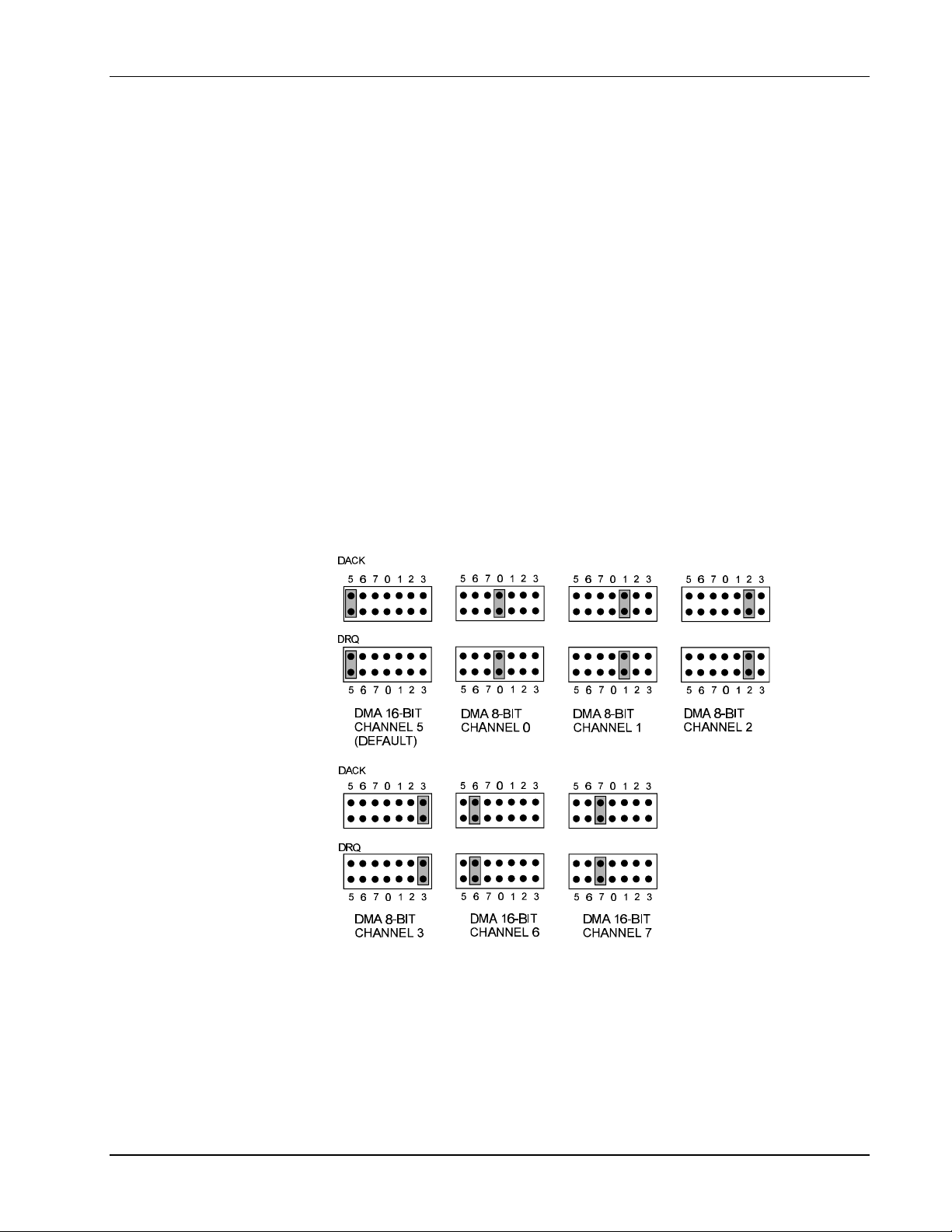
I. HARDWARE GUIDES 3. Personal488/AT
Interrupts 10 through 15 are only available in a 16-bit slot on an AT-class machine. Interrupt 9
becomes synonymous with interrupt 2 when used in a PC/XT bus. The selected interrupt may be
shared among several AT488s in the same PC/AT chassis. The AT488 adheres to the “AT-style”
interrupt sharing conventions. When the AT488 requires service, the IRQ jumper determines which PC
interrupt level is triggered. When an interrupt occurs, the interrupting device must be reset by writing
to an I/O address which is different for each interrupt level. The switch settings determine the I/O
address to which the board’s interrupt rearm circuitry responds. The IRQ jumper and switch settings
must both indicate the same interrupt level for correct operation with interrupts. The previous figure
shows the settings for selected interrupts.
DMA Channel Selection
Direct Memory Access (DMA) is a high-speed method of transferring data from or to a peripheral, such
as a digitizing oscilloscope, to or from the PC’s memory. The AT class machine has seven DMA
channels. Channels 0-3 (8-bit), 5, 6, and 7 (16-bit) are available only in a 16-bit slot on a PC/AT-class
machine. Channel 2 is usually used by the floppy disk controller, and is unavailable. Channel 3 is
often used by the hard disk controller in PCs, XTs, and the PS/2 with the ISA bus, but is usually not
used in ATs. Channels 5 through 7 are 16-bit DMA channels. They offer the highest throughput (up to
1 Megabyte per second). Channels 0 through 3 are 8-bit DMA channels. Although slower, they offer
compatibility with existing GP488B applications that only made use of 8-bit DMA channels. Under
some rare conditions, it is possible for high-speed transfers on DMA channel 1 to demand so much of
the available bus bandwidth that simultaneous access of a floppy controller will be starved for data due
to the relative priorities of the two channels. Both the DRQ and DACK jumpers must be set to the
desired DMA channel for proper operation. Configure the board according to which DMA channel is
available. The following figure shows settings for selecting the DMA channels.
Personal488/AT DMA Selection
Board Installation
The IEEE 488 interface board(s) are installed into expansion slots inside the PC’s system unit. PC/ATcompatible computers have two types of expansion slots: 8-bit (with one card-edge receptacle), and 16bit (with two card-edge receptacles). Eight-bit boards, such as the IEEE 488 interface boards, may be
used in either type of slot, 8- or 16-bit. Some machines may have special 32-bit memory expansion
slots which should not be used for IEEE 488 interface boards.
Personal488 User’s Manual, Rev. 3.0 I-15
Page 32

3. Personal488/AT I. HARDWARE GUIDES
Install each IEEE 488 interface board into the expansion slots as follows: Ensure the PC is turned off
and unplug the power cord. Remove the cover mounting screws from the rear of the PC system unit.
Remove the system unit cover by sliding it forward and tilting it upward.
A rear panel opening is provided at the end of each expansion slot for mounting I/O connectors. If a
slot is unused, this opening is covered by a metal plate held in place with a screw. Remove this screw
and the cover plate from the desired expansion slot, saving the screw.
Insert the IEEE 488 interface board carefully into the expansion slot, fitting the IEEE 488 connector
through the rear panel opening, and inserting its card edge into the motherboard card edge receptacle.
With the board firmly in place, fix its mounting bracket to the rear panel, using the screw removed from
the cover plate.
Slide the system unit cover back on, re-attaching it with the screws. Plug the power cord in and turn on
the PC. If all is well, the system should boot normally. If not, carefully check that none of the I/O
addresses conflict with any other devices or boards. If you are not sure, contact your PC’s dealer or
manufacturer.
I-16 Personal488 User’s Manual, Rev. 3.0
Page 33
I. HARDWARE GUIDES 4. Personal488/NB
4. Personal488/NB
Topics
• • The Package.......................................................................................I-17
• • Hardware Installation (for Notebook, Laptop, & Desktop PCs)I-17
The Package
Personal488/NB, including the IEEE 488 interface hardware and the Driver488 software, is carefully
inspected, both mechanically and electrically, before shipment. When you receive the product, unpack
all items carefully from the shipping carton and check for any obvious signs of physical damage that
may have occurred during shipment. Report any such damage to the shipping agent immediately.
Remember to retain all shipping materials in the event shipment back to the factory becomes necessary.
Personal488/NB includes:
• NB488 IEEE 488 Bus Interface Board
• Driver488 Software Disks (Driver488/DRV, Driver488/SUB & Driver488/W31)
• Printer Port to Interface Cable (CA-35-2)
• Keyboard Port Power Adapter (CA-107)
• AC Power Adapter (TR-2)
• DIN-5 to DIN-6 Adapter (CN-15-6) for CA-107 (Optional; Contact factory if required)
• Driver488 User’s Manual
Hardware Installation (for Notebook, Laptop, & Desktop PCs)
Personal488/NB does not need to be disassembled during installation, as there are no internal switches
or controls to set. Simply connect the Personal488/NB to any PC parallel printer port (female DB25)
by unplugging the printer cable and plugging the supplied cable’s (CA-35-2) male end into the
computer and the female end into the mating connector on the Personal488/NB. Any printer port:
LPT1, LPT2, or LPT3 may be used, but should be noted for future software installation. Next connect
the IEEE 488 cable to the mating connector on the Personal488/NB.
Personal488/NB allows for LPT pass-through for simultaneous IEEE 488 instrument control and
printer operation. When using a printer in the system configuration, attach the original printer cable
(male DB25) into the remaining mating connector on the Personal488/NB.
The Personal488/NB may be powered with a supplied cable (CA-107) from the PC’s keyboard port or
via a supplied external power unit (TR-2) that plugs into any standard AC wall outlet.
If powering the unit through the PC keyboard port, attach the supplied power cord to the keyboard port
and connect to the power jack on the Personal488/NB. If using an AC power adapter, plug it into a
120 VAC outlet and attach the low voltage end to the jack on the Personal488/NB. The POWER LED
should now be on and hardware installation complete.
At power-on, the printer should behave normally and can be checked by issuing a Print Screen
command (or any other convenient method of checking the printer). However, installation of the
software will be necessary before the Personal488/NB can communicate with IEEE 488 instruments.
Once the NB488 is installed, a utility program has been included to help identify the LPT port type.
Software installation requires the user to specify whether the LPT port is a standard IBM
PC/XT/AT/PS/2 compatible port or a slower 4-bit option. Type NBTEST.EXE to run this program.
Personal488 User’s Manual, Rev. 3.0 I-17
Page 34
5. Personal488/MM I. HARDWARE GUIDES
5. Personal488/MM
Topics
• • The Package...................................................................................... I-18
• • Hardware Installation (for PC/XT/AT)........................................ I-18
Installation & Configuration of the Interface Card ................................. I-18
Default Settings .............................................................................................. I-18
I/O Base Address Selection ............................................................................ I-19
Interrupt Selection ......................................................................................... I-20
DMA Channel Selection ................................................................................. I-20
Internal Clock Selection ................................................................................ I-21
Board Installation.......................................................................................... I-21
The Package
Personal488/MM, including IEEE 488 interface board and Driver488 software, is carefully inspected,
both physically and electronically, before shipment. When you receive the product, carefully remove
all items carefully from the shipping carton and check for any obvious signs of physical damage that
may have occurred during shipment. Report any such damage to the shipping agent immediately.
Remember to retain all shipping materials in the event shipment back to the factory becomes necessary.
The Personal488/MM includes:
• GP488/MM IEEE 488 Bus Interface Board
• Driver488 Software Disks
(Driver488/DRV, Driver488/SUB, Driver488/W31 & Driver488/W95)
• Personal488 User’s Manual
Hardware Installation (for PC/XT/AT)
Installation & Configuration of the Interface Card
The following paragraphs explain configuration and physical installation of the interface card.
Software installation and setup are covered in a separate section. After configuring your board, please
make note of the following. This information is needed for Driver488 software installation.
• I/O Base Address
• Interrupt Channel
• DMA channel, if applicable
• Whether or not the board is the System Controller
Note: The GP488/MM is only compatible with the Ampro PC/104. The board includes one DIP
switch, two 12-pin headers and one 3-pin header, labeled SW1, JP2, JP3, and JP1,
respectively. The DIP switch setting, along with the arrangement of the jumpers on the
headers, set the hardware configuration.
I-18 Personal488 User’s Manual, Rev. 3.0
Page 35

I. HARDWARE GUIDES 5. Personal488/MM
Default Settings
There are presently two revision levels of GP488/MM board, Rev. A and Rev. B. The following figure
indicates the GP488/MM default configuration on a Rev. B board. The configuration is the same for
Rev. A, however, on Rev. A boards the JP2 and JP3 labels are reversed from that illustrated. Switch
SW1 controls the wait state generation and the I/O base address and interrupt response level. On the
Rev. B board, JP2 sets the interrupt request level and JP3 selects the DMA channel. On Rev. A boards,
the JP2 and JP3 labels are reversed from those shown in the following diagram. For both board
revision levels JP1 selects the clock source.
I/O Base Address Selection
The I/O base address sets the addresses used by the computer to communicate with the IEEE 488
interface hardware on the board. The address is normally specified in hexadecimal and can be 02E1,
22E1, 42E1, or 62E1. The registers of the IOT7210 IEEE 488 controller chip and other auxiliary
registers are then located at fixed offsets from the base address.
Most versions of Driver488 are capable of managing as many as four IEEE 488 interface boards. To
do so, the board configurations must be arranged to avoid conflict among themselves. No two boards
may have the same I/O address, but they may, and usually should, have the same DMA channel and
interrupt level.
The factory default I/O base address is 02E1. To use another, set SW1 switches 4 and 5 according to
the following table and figure.
I/O Base Address Register
02E1 22E1 42E1 62E1
02E1 22E1 42E1 62E1
06E1 26E1 46E1 66E1
0AE1 2AE1 4AE1 6AE1
0EE1 2EE1 4EE1 6EE1
12E1 32E1 52E1 72E1
16E1 36E1 56E1 76E1
1AE1 3AE1 5AE1 7AE1
1EE1 3EE1 5EE1 7EE1
Read Register Write Register
Data In Data Out
Interrupt Status 1 Interrupt Mask 1
Interrupt Status Interrupt Mask 2
Serial Poll Status Serial Poll Mode
Address Status Address Mode
CMD Pass Through Auxiliary Mode
Address 0 Address 0/1
Address 1 End of String
Personal488 User’s Manual, Rev. 3.0 I-19
Page 36
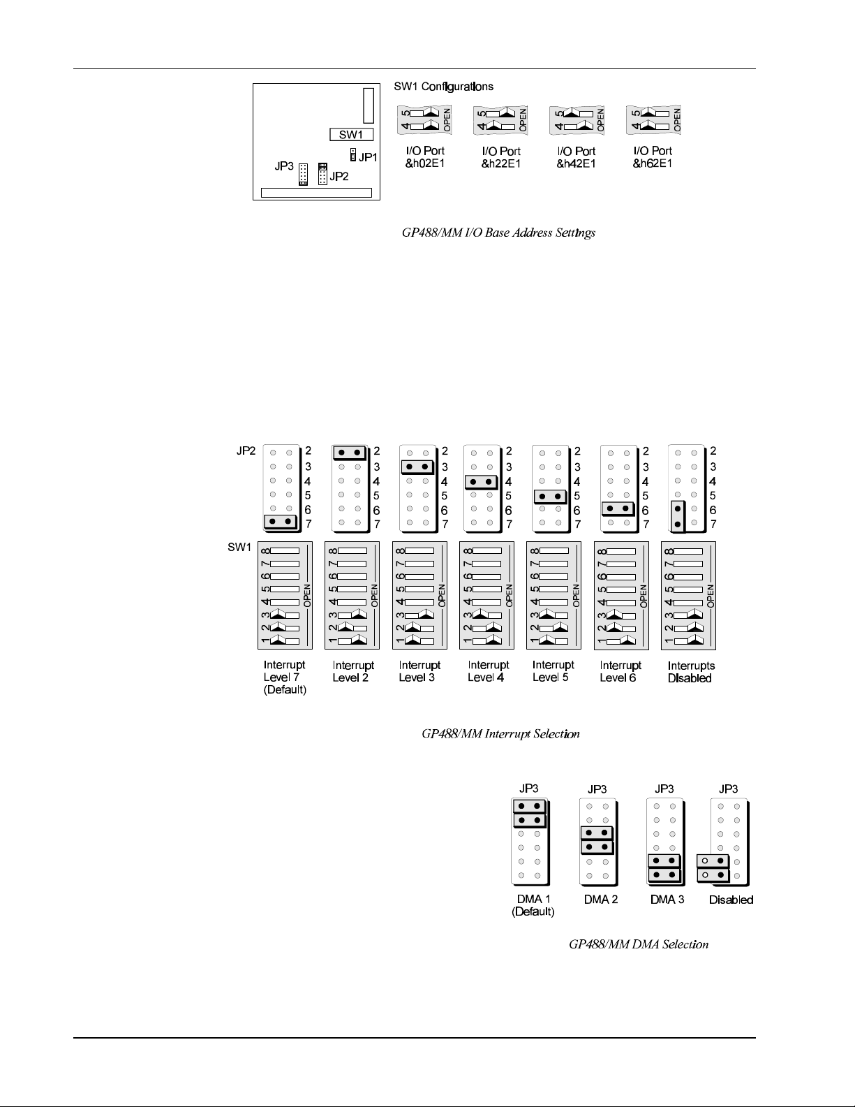
5. Personal488/MM I. HARDWARE GUIDES
Interrupt Selection
The GP488/MM interface board may be set to interrupt the PC on the occurrence of certain hardware
conditions. The level of the interrupt generated is set by JP3 on Rev. B boards (JP2 on Rev. A boards).
The GP488/MM interface board adheres to the “AT-style” interrupt sharing conventions. When an
interrupt occurs, the interrupting device must be reset by writing to I/O address 02FX, where X is the
interrupt level (from 0-7). This interrupt response level is set by switches 1, 2, and 3 of SW1 which
must be set to correspond to the JP3 (Rev. B board) interrupt level setting. Interrupt selection for a
Rev. B board is illustrated in the following figure.
Note: The jumper label would read JP2 for Rev. A boards.
DMA Channel Selection
Direct Memory Access (DMA) is a high-speed method of
transferring data from or to a peripheral, such as a
digitizing oscilloscope, to or from the PC’s memory.
The factory default selection is DMA channel 1. Note
that jumper JP2 is used to configure revision B boards
while the jumper labeled JP3 is used to select the DMA
channel on version A boards.
Note: Check your computer documentation to ensure
the selected DMA channel is not being used by
another device. The GP488B/MM board has
circuitry which allows for more than one
GP488/MM board to share the same channel.
Most computers use DMA channel 2 for floppy
disk drives, making that channel unavailable.
I-20 Personal488 User’s Manual, Rev. 3.0
Page 37
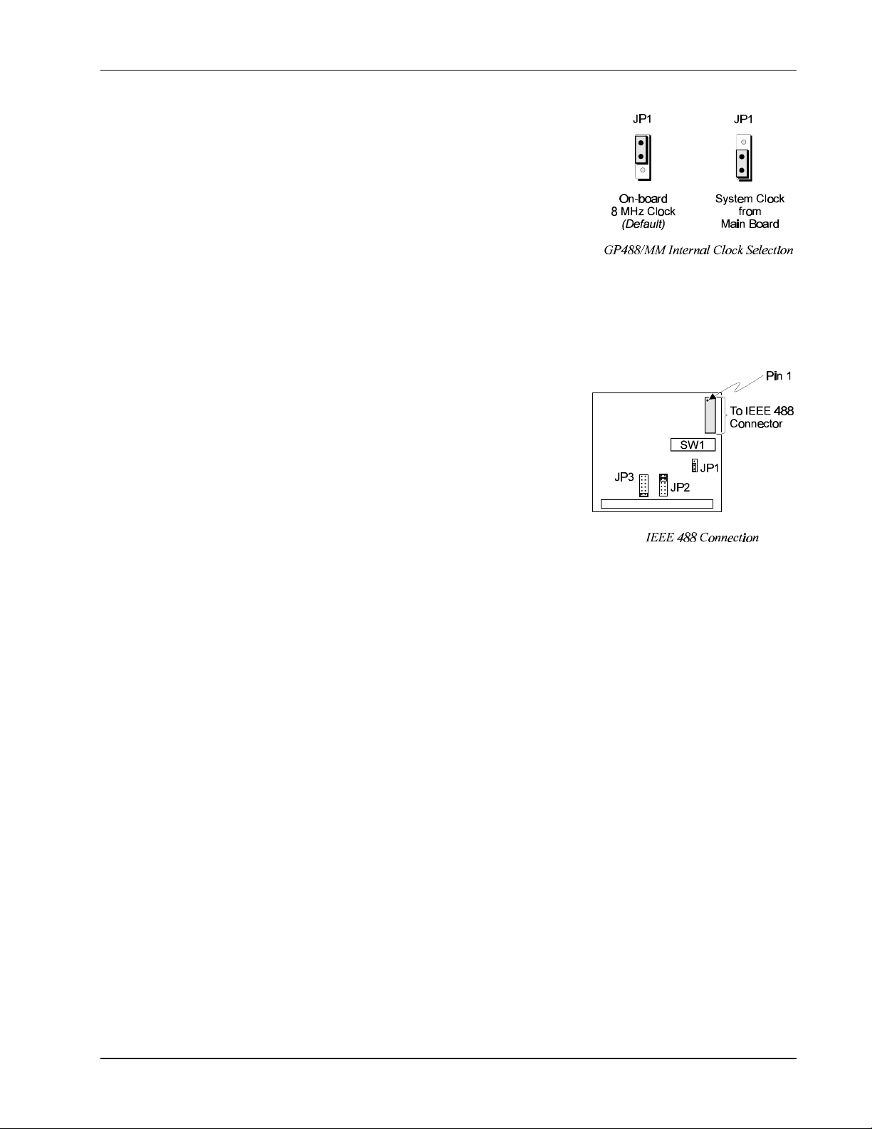
I. HARDWARE GUIDES 5. Personal488/MM
Internal Clock Selection
The IEEE 488 bus interface circuitry requires a master clock. This
clock is normally connected to an on-board 8 MHz clock oscillator.
However, some compatible IEEE 488 interface boards connect this
clock to the PC’s own clock signal. Using the PC clock to drive
the IEEE 488 bus clock is not recommended because the PC clock
frequency depends on the model of computer. A standard PC has a
4.77 MHz clock, while an AT might have a 6 MHz or 8 MHz
clock. Other manufacturers’ computers may have almost any
frequency clock. If you are using a software package designed for
an interface board (that derived its clock from the PC clock) and
you need to do the same to use GP488/MM with that particular
software, the clock source can be changed. However, the clock frequency must never be greater than 8
MHz, and clock frequency must be correctly entered in the Driver488 software.
Board Installation
IEEE 488 interface board(s) are installed into expansion slots
inside the PC’s system unit. PC/AT-compatible computers have
two types of expansion slots: 8-bit (with one card-edge
receptacle), and 16-bit (with two card-edge receptacles). Eightbit boards, such as the IEEE 488 interface boards, may be used
in either type of slot, 8- or 16-bit. Some machines may have
special 32-bit memory expansion slots which should not be used
for IEEE 488 interface boards.
Install each IEEE 488 interface board into the expansion slots as
follows: Ensure the PC is turned off and unplug the power cord.
Remove the cover mounting screws from the rear of the PC
system unit. Remove the system unit cover by sliding it forward and tilting it upward.
A rear panel opening is provided at the end of each expansion slot for mounting I/O connectors. If a
slot is unused, this opening is covered by a metal plate held in place with a screw. Remove this screw
and the cover plate from the desired expansion slot, saving the screw.
Insert the IEEE 488 interface board carefully into the expansion slot, fitting the IEEE 488 connector
through the rear panel opening, and inserting its card edge into the motherboard card edge receptacle.
With the board firmly in place, fix its mounting bracket to the rear panel, using the screw removed from
the cover plate.
Slide the system unit cover back on, re-attaching it with the screws. Plug the power cord in and turn on
the PC. If all is well, the system should boot normally. If not, carefully check that none of the I/O
addresses conflict with any other devices or boards. If you are not sure, contact your PC’s dealer or
manufacturer.
Personal488 User’s Manual, Rev. 3.0 I-21
Page 38

6. Personal488/CARD I. HARDWARE GUIDES
6. Personal488/CARD
Topics
• • The Package...................................................................................... I-22
• • Introduction...................................................................................... I-22
• • Hardware Installation (for Notebook & Desktop PCs) ........... I-23
Interfaces & Connectors ................................................................................ I-23
Interface Cable Connection........................................................................... I-23
Installation into a PC .................................................................................... I-24
Interface Cable & IEEE 488 Accessories ..................................................... I-24
• • Software Installation ...................................................................... I-24
Initialization Software .................................................................................. I-24
Configuration Software ................................................................................. I-27
• • Functionality .................................................................................... I-29
The Package
The Personal488/CARD components were carefully inspected prior to shipment. After receiving your
order, carefully unpack all items from the shipping carton and check for any signs of physical damage
which may have occurred during shipment. Immediately report any damage to the shipping agent.
Retain all shipping materials in case you must return the unit to the factory. If the unit is damaged, a
RMA # (Return Material Authorization Number) must be obtained before returning it. An RMA # can
be obtained by calling (216) 439-4091 or your sales representative.
Every Personal488/CARD is shipped with the following items:
• IEEE 488 PCMCIA interface Card
• Interface Cable (CA-137)
• • Initialization Software: Client Driver, and Enabler
• • Driver Software (Programming Support including Configuration Utilities):
Driver488/DRV, Driver488/W31, and Driver488/SUB
• • Personal488 User’s Manual
Introduction
The Personal488/CARD is a low-power Type II PCMCIA IEEE 488 interface that enables IEEE 488.2
control from notebook and desktop PCs. This card plugs into any Type II (5mm) PCMCIA socket and
is PCMCIA PC Card Standard Specification 2.1 compliant. CardSoftTM Card and Socket services are
available on the majority of notebook PCs currently sold. If your notebook has different software, you
may purchase the CardSoftTM software from the Personal488/CARD manufacturer. The
Personal488/CARD does not require an ISA-bus expansion slot or external power.
The Personal488/CARD is highly flexible with respect to I/O addressing and interrupt level use. It can,
by default, automatically configure itself upon insertion into your notebook or desktop PC or upon
system startup. In addition, users may specify any interrupt level and any I/O space base address for
the Personal488/CARD. The card permits “Hot-Swapping”, that is, insertion of the PCMCIA card
while the system is powered.
I-22 Personal488 User’s Manual, Rev. 3.0
Page 39
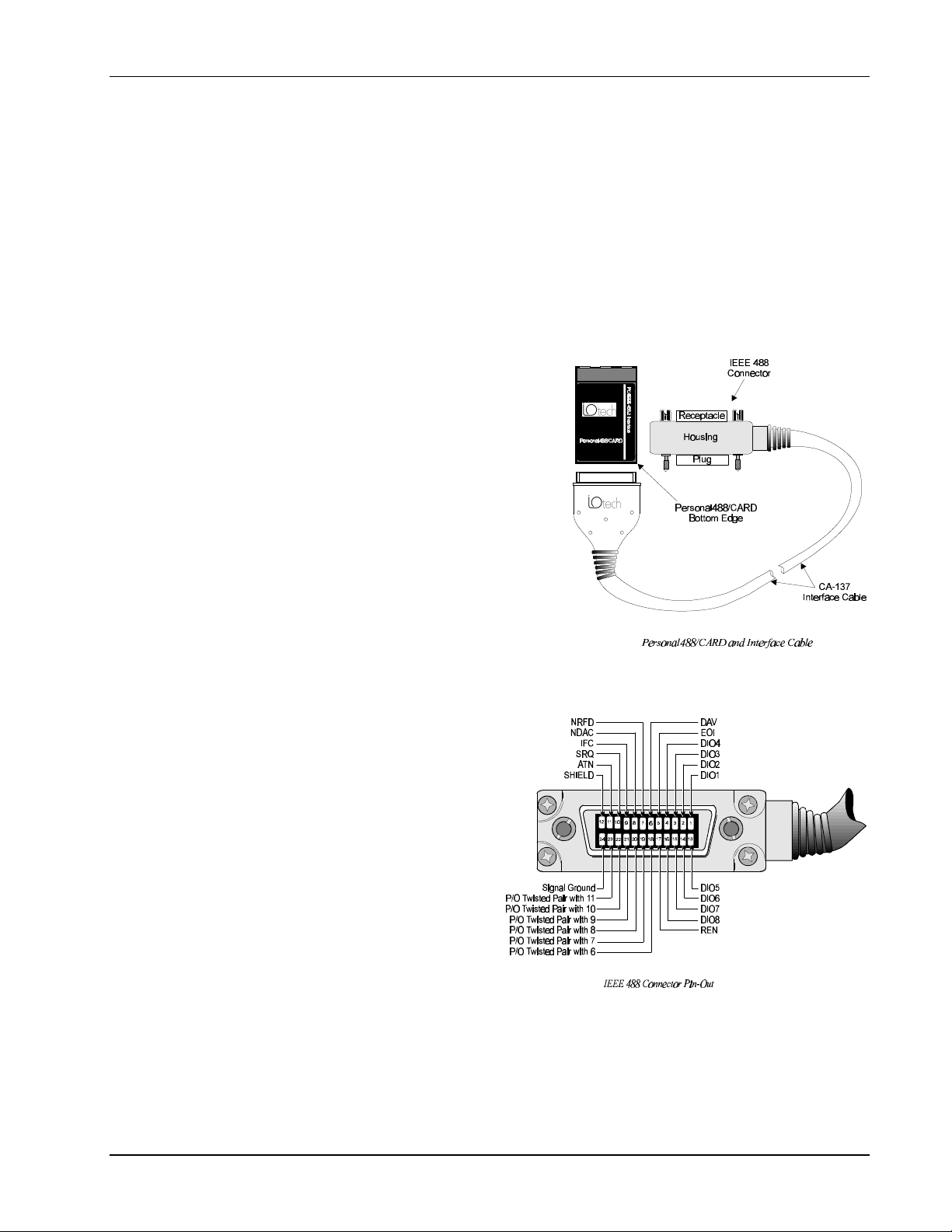
I. HARDWARE GUIDES 6. Personal488/CARD
Hardware Installation (for Notebook & Desktop PCs)
Hardware installation topics are covered in the following paragraphs. It is strongly suggested that you
read and perform the following instructions to assure the proper installation and usage of the
Personal488/CARD.
The hardware installation topics include:
• Personal488/CARD-to-Interface Cable connection
• Installation of Personal488/CARD into PC
• Interface Cable connection with IEEE 488 compatible accessories
The plug and play operation of the Personal488/CARD allows for the operating parameters to be
configured via software, circumventing the need for switch or jumper settings.
Interfaces & Connectors
The Personal488/CARD is shipped with an interface
cable (CA-137) that permits the card to directly
interface with up to fourteen (14) IEEE 488
instruments.
The PCMCIA card connects to the CA-137 cable via
the female slot connector found along its “bottom”
edge, as shown in the figure. The unit itself, being a
PCMCIA socket card, constitutes a Type II (5mm)
PCMCIA socket interface.
The opposite end of the CA-137 Interface Cable is
terminated in an IEEE 488 connector with metric
studs. A pin-out of this connector is provided below.
Interface Cable Connection
Follow the instructions below to connect the Personal488/CARD to the Interface Cable (CA-137).
Note: The PCMCIA Card and the Slot
Connector End of the Interface
Cable are keyed to ensure proper
connection. The card and cable
should connect easily and fit
snug. DO NOT force the
PCMCIA Card / Interface
Cable mating. Refer to the
figures on this page while
performing these instructions.
1. In one hand, hold the PCMCIA Card
so that the company logo is face up
and the bottom edge of the card is
facing you.
2. In the other hand, hold the Slot
Connector End of the Interface Cable
so that the groove (keyed portion of the connector) is face down and the company logo is face up.
3. Press the Slot Connector into the PCMCIA Card. The Personal488/CARD should now be firmly
connected to the Interface Cable.
Note: The slot connector is keyed to match the PCMCIA Card so that an improper connection can
not be made. Therefore, DO NOT force this connection as damage may result! For proper
contact, the connection of the card and cable must be snug.
Personal488 User’s Manual, Rev. 3.0 I-23
Page 40

6. Personal488/CARD I. HARDWARE GUIDES
Installation into a PC
With your PC powered-down (turned off), install your Personal488/CARD using the instructions
provided below.
Note: If the Client Driver Software is used, you are not required to power down your PC before
installing the Personal488/CARD. The Client Driver Software enables insertion and removal
of the card into any Type II socket at any time, and automatically configures the card upon its
insertion (“Hot-Swapping”).
Note: Enabler Software, on the other hand, does not allow “Hot-Swapping.” More detailed
information is provided later in this chapter.
Note: “Hot-Swapping” refers to the insertion and removal of the PCMCIA card while the system is
powered.
1. With your PC powered down (turned off), insert the PCMCIA Card into the PCMCIA socket with
the company logo face up (for most Notebook PCs).
2. Push the PCMCIA Card into the PCMCIA socket as if you were loading a diskette into a diskette
drive. Stop once the card is engaged into the socket. This is marked by hearing a “click” and
seeing that the socket eject button has been engaged (pushed out).
Note: CardSoft™ Card and Socket Services are available on the majority of notebook PCs currently
sold. If your notebook has incompatible software, you may purchase the CardSoft™ software
from the Personal488/CARD manufacturer.
Interface Cable & IEEE 488 Accessories
Only IEEE 488 compatible accessories (instruments) can interface with the Personal488/CARD. The
Personal488/CARD and cable permit a fan-out of fourteen (14) directly interfaced IEEE 488
instruments.
1. Plug the IEEE 488 connector end of the Interface Cable into any compatible IEEE 488 accessories.
2. With your fingers and/or applicable flat bladed screw driver, tighten the screw pins (metric studs)
located on the IEEE 488 connector to secure the connection.
Note: You will need additional IEEE 488 interface cables (terminated at both ends with IEEE 488
connectors) for subsequent IEEE 488 instruments.
At this point, the default configuration of the Personal488/CARD will be used. The default
configuration is the initialization of the “CARD” upon system boot-up having not used the Client
Driver or Enabler to make changes to the “CARD’s” settings. Once all connections have been
checked for correctness, the “system” can be powered up. If communication problems exist due to
initialization conflicts, the Client Driver or Enabler will have to be installed in order to make
initialization changes. This subject is covered in the following paragraphs.
Note: The Client Driver or Enabler is needed even if there are no configuration conflicts but a desire
to change the Personal488/CARD’s configuration to meet predetermined specifications and/or
needs.
Software Installation
The Personal488/CARD is provided with both Initialization and Configuration Software (the
Configuration Software is driver specific and therefore included with each driver). This text introduces
support for the Initialization Software (Client Driver and Enabler). For more information, refer to the
driver-specific “Installation & Configuration” Sub-Chapters found in Chapters 8 through 12. The
following drivers are available for the Personal488/CARD: Driver488/DRV, Driver488/SUB, and
Driver488/W31.
I-24 Personal488 User’s Manual, Rev. 3.0
Page 41

I. HARDWARE GUIDES 6. Personal488/CARD
Initialization Software
Initialization of the Personal488/CARD is software oriented. The Client Driver and Enabler files
conform to the PCMCIA (PC Card) Card Services Specification 2.1. When used with CardSoft™ Card
and Socket Services (or compatible) software, the Personal488/CARD automatically configures itself
upon system start-up. The use of CardSoft™ is not required, however, the chosen utility software must
be compatible with the PCMCIA (PC Card) Card Services Specification 2.1.
If you need to control which resources the Personal488/CARD utilizes, you must load either the Client
Driver or Enabler, but not both. The Personal488/CARD’s resources are IRQ level, base I/O port
address for sixteen consecutive ports, and PCMCIA Type II socket number (with 0 being the first
socket).
Using the Client Driver
The Client Driver sets the IRQ, Socket # (if more than one PCMCIA socket is available), and an I/O
Address Range for communication purposes. The settings which result are referred to as default.
There is no predetermined default setting since these settings depend on what the Client Driver finds
vacant and, therefore, usable. This does not take into account transparent devices not seen by the
Client Driver.
Note: Depending on your system configuration, the default settings may conflict with the IRQ,
Socket #, and I/O Address Range that your system has already allocated to another device. If
this is the case, change the initialization settings as described below.
Using the Enabler
The Enabler performs the same function of setting up the needed system resources as the Client Driver,
but in a more direct and somewhat limited way. The only real advantage of using the Enabler is the
amount of PC memory rescued (about 7 kb). This memory would be used indefinitely by the Client
Driver, since the Client Driver must store a program in memory to manage “Hot-Swapping.” If the
Card and Socket Services are only needed for the Client Driver, you could save more memory by not
loading them when using the Enabler.
On the down side of using the Enabler, the Personal488/Card must be installed before you run the
Enabler. Also, every time the Personal488/Card is removed, and reinstalled, the Enabler must be run.
The Enabler requires explicit IRQ, Socket #, and I/O Address Range parameters. If Card and Socket
Services are running, they will not know that the Enabler allocated some resources, and may therefore
allocate them to another device.
Changing Initialization Settings
Use the following steps to change the initialization settings, or to initialize the Personal488/CARD
system to your specifications and/or needs.
Note: If your PC has a valid version of PCMCIA Card and Socket Services software, it is
recommended that you use Client Driver, since Client Driver supports
Note: “Hot-Swapping” refers to the insertion and removal of the PCMCIA card while the system is
powered.
1. Choose between the Client Driver (IOT488CL.SYS) or Enabler (IOT488EN.EXE) files as to which
one best suits your needs. The choice heavily depends upon the host computer environment and
the desire for Plug and Play functionality.
2. If you choose the Client Driver file option, you will need to update your CONFIG.SYS file by
adding the following command line:
DEVICE=path\IOT488CL.SYS options
3. The Personal488/CARD must be installed before using the Enabler. The initialization is only valid
as long as the Personal488/CARD is present. You will need to update your AUTOEXEC.BAT file
with the following command line:
path\IOT488EN.EXE options
Personal488 User’s Manual, Rev. 3.0 I-25
Page 42
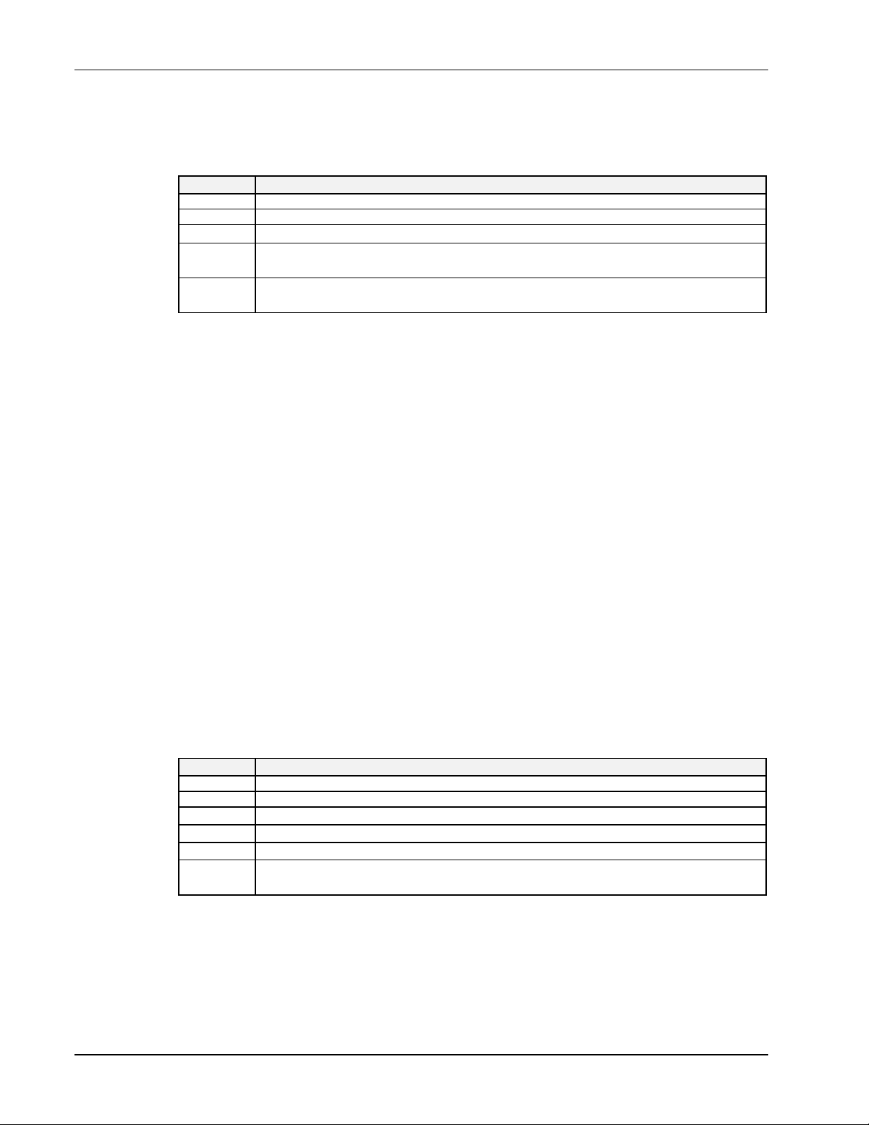
6. Personal488/CARD I. HARDWARE GUIDES
Client Driver
The Client Driver has the following CONFIG.SYS file line syntax:
DEVICE=path\IOT488CL.SYS [ (GROUP) [ (GROUP) [ ... ]]]
where the following parts are described as follows:
Part Client Driver Description
GROUP [ITEM[,ITEM[,ITEM]]]
ITEM Sxx | Bxxx | Ixx
Sxx
Bxxx
The socket number, xx in [0...15], default to any available socket, if omitted.
The I/O base address (hex), xxx in [100...3F0], default to any available I/O
address, if omitted.
Ixx
The IRQ level, xx in [0...15], 0 means no interrupt, default to any available IRQ
level, if omitted.
IOT488CL.SYS
The simplest command line, shown above, will configure the card in any PCMCIA socket with
available consecutive 16 bytes in the system I/O space, and an available IRQ level. Note that you
should not assume the resource selections will always be the same.
IOT488CL.SYS (s0,b300,i5)
The command line above will configure the card in socket 0 with I/O base address at 300H and IRQ
level 5, if those resources are available.
IOT488CL.SYS (b300,i5) (i10) ( )
This command line tells the client driver to configure the card in any socket with a base address of
300H and IRQ 5. If not available, the client driver will then try to configure it with a base address and
socket number assigned by the Card and Socket Services and IRQ 10. If IRQ 10 is not available, the
Client Driver will then try to configure the card with a base address, socket number, and an IRQ level
assigned by the Card and Socket Services.
Space characters are only allowed in between the groups, not inside a group. The items within a group
are separated by a single comma. The order of items in a group does not make any difference. Nor are
the characters in an item case sensitive.
Enabler
The command line syntax for the Enabler is similar to that used by the Client Driver.
DEVICE=path\IOT488EN.EXE (Sxx,Bxxx,Ixx[,Wxx])
where the following parts are described as follows:
Part Enabler Description
GROUP [ITEM[,ITEM[,ITEM]]]
ITEM Sxx | Bxxx | Ixx
Sxx
Bxxx
Ixx
Wxx
The same as the Client Driver syntax, except it must be specified to enable the card.
The same as the Client Driver syntax, except it must be specified to enable the card.
The same as the Client Driver syntax, except it must be specified to enable the card.
Specifies the PCIC memory window, xx (hex) in [80...EF], default to D0 if
omitted.
IOT488EN.EXE (Sxx,R[,Wxx])
To reset the card, the command line syntax above can be used, in which R is the reset switch. Socket
number must be specified, but Wxx can be omitted (default memory window at D0000H). After
executing an IOT488EN.EXE command with the reset option, IOT488EN.EXE must be run again to set
the card’s resources.
I-26 Personal488 User’s Manual, Rev. 3.0
Page 43

I. HARDWARE GUIDES 6. Personal488/CARD
IOT488EN.EXE (s0,r)
This command line resets the card in socket 0 (default memory window at D0000H),
IOT488EN.EXE (s1,r,wc8)
This command line resets the card in socket 1 (with PCIC memory window at C8000H).
Configuration Software
For ease of use, this text repeats material found in the driver-specific “Installation & Configuration”
Sub-Chapters found in Chapters 8 through 12 of this manual. In addition, this text includes
Personal488/CARD information not contained elsewhere. Aside from this chapter on
Personal488/CARD, you should also read through the “External Device Interfacing” Sub-Chapters
found in Chapters 8, 9, and 10 of this manual.
Configuration Utility
The configuration utility permits you to specify the Driver488 system configuration, add interfaces,
define external devices, etc. It does so by modifying the Driver488 startup configuration and is
specified in a Windows-style initialization file named DRVR488.INI. The first screen of the
CONFIG.EXE program is used to enter the configuration settings so the Driver488 software can be
correctly modified to reflect the state of the hardware.
The driver can be reconfigured at any time by running the CONFIG.EXE program. Changes to the
configuration will not be recognized by the driver until the driver is unloaded and reloaded. Typically,
this is accomplished by rebooting your computer or using the utilities MARKDRVR and REMDRVR. For
details regarding utilities, refer to the “Utility Programs” Sub-Chapters found in Chapters 8, 9, and 10
of this manual
To start the CONFIG program, type CONFIG within the directory in which the configuration utility
resides, typically C:\IEEE488.
The minimum requirement for configuring your system is to make certain that your Personal488/CARD
is selected under “Device Type.” The default settings in all of the other fields match those of the
interface as shipped from the factory. If you are unsure of a setting, it is recommended that you leave it
as is.
Interfaces and External Devices
The CONFIG program can configure both interfaces and external devices. Interfaces are the
Personal488/Card and serial ports. External devices are instruments or other devices attached to the
IEEE 488 bus or the MP488(CT) Counter/Timers and Digital I/O devices.
Configuration Program Screens
In general, all Driver488 configuration utility screens have three main windows: the “name” of the
interfaces or devices on the left, the “configuration” window on the right, and the “instruction” window
at the bottom of the screen. Based on current cursor position, the valid keys for each window will
display in the Instructions box.
To begin the interface configuration, move the cursor in the name window to select an interface
description for modification. (Interfaces can be added or deleted using <F3> and <F4>). Notice
moving the cursor up and down the list of interfaces or devices in the left window changes the
parameters in the configuration window. The configuration fields always correspond with the currently
selected interface and device type.
Once all modifications have been made to the configuration screen, <F10> must be pressed to accept
the changes made or <F9> can be pressed to exit without saving any change. Additional function keys
allow the user to continue onto the configuration of external devices via <F5> or to view a graphic
representation of the interface card with the selected settings via <F7>.
Configuring Driver488 Interfaces
Driver488 supports two types of interfaces: IEEE and Serial. Once the CONFIG.EXE program is
entered, highlight the Device Type selection from the Configuration Window and choose the
Personal488 User’s Manual, Rev. 3.0 I-27
Page 44
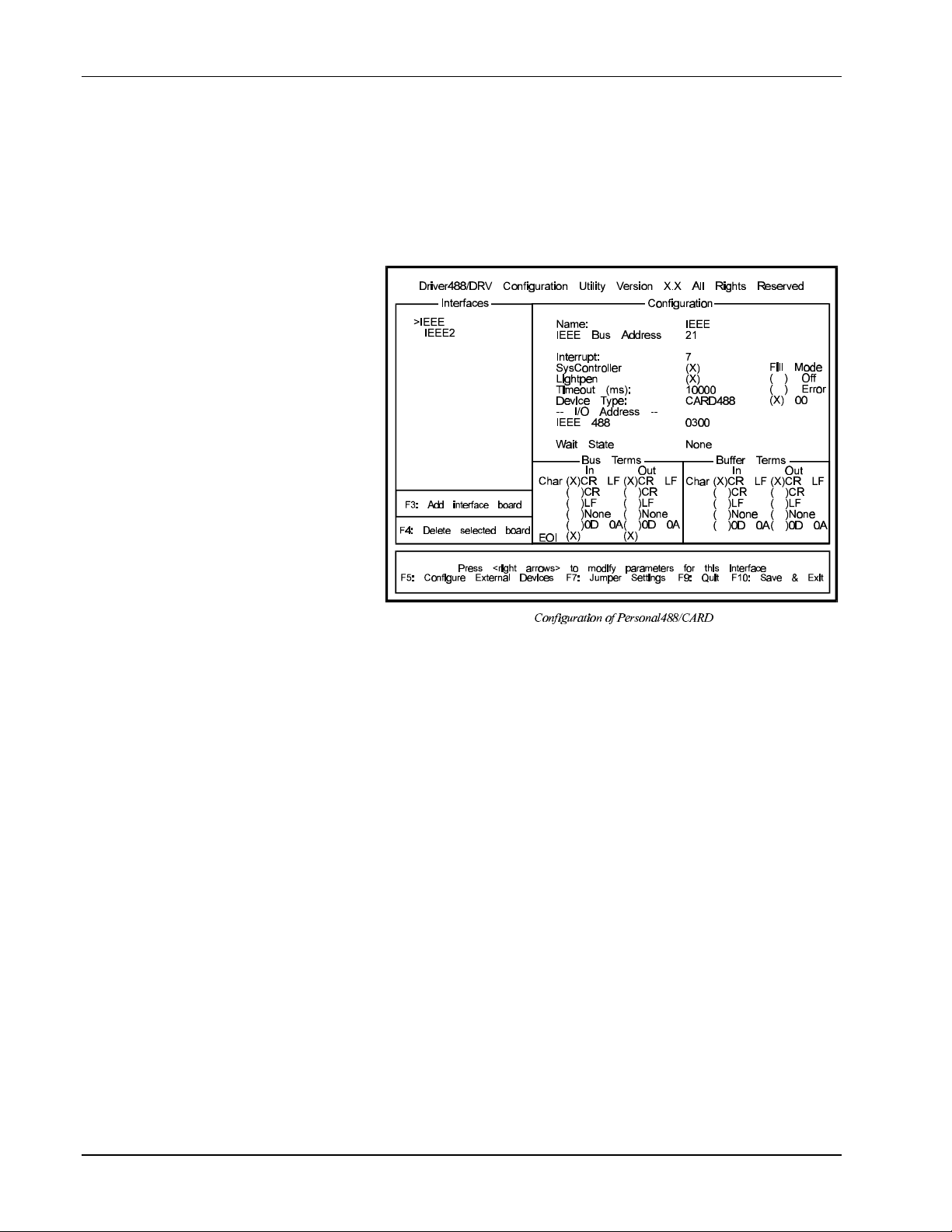
6. Personal488/CARD I. HARDWARE GUIDES
CARD488 option from the resulting pop-up menu. The Driver488/DRV screen, shown next, or one
similar, will be displayed.
Once an interface is selected, the fields and default entries which appear in the configuration window
depend on the device type specified. To add another IEEE interface, select <F3>. If you will be using
more than one interface, refer to other sections of this manual for additional information, as needed.
The configuration parameters of the IEEE interface are described following the figure of the
Driver488/DRV screen.
Configuration Parameters
• Name: This field is a
descriptive instrument
name which is
manually assigned by
the user. This must be
a unique name.
Typically, IEEE or
COM is used (up to 8
characters).
• IEEE Bus Address:
This is the setting for
the IEEE bus address
of the board. It will be
checked against all the
instruments on the bus
for conflicts. It must
be a valid IEEE bus
address from 0 to 30.
• Interrupt: A
hardware interrupt
level can be specified to improve the efficiency of the I/O adapter control and communication
using Driver488. Personal488/CARDs may not share the same interrupt level. If no interrupt level
is to be used, select NONE. Valid interrupt levels depend on the type of interface, since interrupt
sharing is not permitted in the PCMCIA 2.1 specification. Settings are as follows: Levels 3-7,
Levels 9-12, Levels 14-15, or NONE.
• SysController: This field determines whether or not the Personal488/CARD is to be the System
Controller. The system controller has ultimate control of the IEEE 488 bus, and the ability of
asserting the interface clear (IFC) and remote enable (REN) signals. Each IEEE 488 bus can have
only one system controller. If the PCMCIA IEEE Card is a peripheral, it may still take control of
the IEEE 488 bus if the Active Controller passes control to it. The “CARD” may then control the
bus and, when it is done, pass control back to the System Controller or another controller, which
then becomes the active controller. If the “CARD” will be operating in Peripheral mode (not
System Controller), leave this field blank.
• LightPen: This field determines whether the LightPen command is to be used. If selected, it will
disable the detection of interrupts via setting the light pen status. The default is light pen interrupt
enabled.
• Timeout (ms): The time out period is the amount of time that data transfers wait before assuming
that the device does not transfer data. If the time out period elapses while waiting to transfer data,
an error signal occurs. This field is the default timeout for any bus request or action, measured in
milliseconds. If no timeout is desired, the value may be set to zero.
• Device Type: This field specifies the type of board or module, in this case a Personal488/CARD
(CARD488), represented by the IEEE device name selected.
I-28 Personal488 User’s Manual, Rev. 3.0
Page 45

I. HARDWARE GUIDES 6. Personal488/CARD
I/O Address
• IEEE 488: This field is the I/O base address which sets the addresses used by the computer to
communicate with the IEEE interface hardware on the board. The address is specified in
hexadecimal and can be 100 through 3F0 on even 16-byte boundaries (those ending in 0). The
Personal488/CARD uses sixteen (16) consecutive I/O ports.
Note: Since many I/O ports in the allowed range are [or may be] in use by other system hardware,
we recommend using port 300 to 360 hex. Using a port already in use could cause loss of
data, or physical damage.
• Wait State: Wait States can be generated if IEEE 488 bus I/O synchronization between the
Personal488/CARD and PC is an issue. It should be noted that the time out specification is
independent of wait state(s). The Personal488/CARD is fast enough to be compatible with
virtually every PC/XT/AT-compatible computer on the market. Even if the computer is very fast,
the processor is normally slowed to 8 MHz or below when accessing the I/O channel. If the I/O
channel runs faster than 8 MHz, it may be faster than the Personal488/CARD. If this is a
suspected problem, the computer can be made to wait for the “CARD” by enabling wait states.
Increasing the number of wait states slows down the access to the “CARD”. The overall resultant
performance degradation is usually only a few percent.
• Bus Terminators: The IEEE 488 bus terminators specify the characters and/or end-or-identify
(EOI) signal that are to be appended to data that is sent to the external device, or mark the end of
data that is received from the external device.
In conclusion, to save your changes to disk press <F10>. All changes will be saved in the directory
where you installed Driver488. If at any time you wish to alter your Driver488 configuration, simply
rerun CONFIG. The changes made will not take effect until the system is rebooted (Warm or Cold).
Driver488/W31 Configuration Utility
The configuration utility provided with Driver488/W31 has been updated to provide a familiar
Windows user interface. The interface contains the same characteristics as the DOS configuration
program, however, the file storage differs as indicated by the table below.
Driver Version File Name File Location
Windows
DOS
Functionality
The Personal488/CARD transfers data to the host computer via the PCMCIA interface. This interface
provides access to the PC’s data bus, allowing real-time data collection and storage to disk at 1.0 M
byte/sec.
The Personal488/CARD built-in 7210 controller device controls the IEEE 488 bus using the IOT7210
Controller Chip, which is 100% compatible with the NEC µPD7210. However, the IOT7210 exhibits
better performance and lower power consumption.
The programmed I/O mode allows the host computer to acquire individual data samples or large blocks
of data under application control.
The interrupt transfer mode allows the host computer to perform other tasks until the
Personal488/CARD has sent or received a programmed amount of data. This mode provides the most
efficient use of computer resources and data transfer.
DRVR488W.INI
DRVR488.INI
Driver File Storage
WIN.COM (in Windows Directory)
CONFIG.EXE (in assigned directory)
Note: For more information on the functionality of the Personal488/CARD, refer to the “Data
Transfers,” “Operating Modes,” and “Command Descriptions” Sub-Chapters found in
Chapters 8 and 9 of this manual.
Personal488 User’s Manual, Rev. 3.0 I-29
Page 46

6. Personal488/CARD I. HARDWARE GUIDES
I-30 Personal488 User’s Manual, Rev. 3.0
Page 47

Section II:
SOFTWARE GUIDES
Personal488 User’s Manual, Rev. 3.0 II-31
Page 48

II-32 Personal488 User’s Manual, Rev. 3.0
Page 49
II. SOFTWARE GUIDES 7. Overview
II. SOFTWARE GUIDES
Chapters
7. Overview........................................................................................ II-33
8. Driver488/DRV.............................................................................. II-34
9. Driver488/SUB ............................................................................ II-133
10. Driver488/W31........................................................................... II-191
11. Driver488/W95........................................................................... II-257
12. Driver488/WNT ......................................................................... II-258
7. Overview
The Software Guides section contains chapters pertaining to various Driver488 software. Information
includes instruction for installation and configuration, device interfacing, and API (Application
Program Interface) command references. Note that more detailed topic-specific tables of contents are
included with each of the topics identified above.
In addition to this manual, Power488 and PowerCT users receive a manual supplement describing the
Standard Commands for Programmable Instruments (SCPI) command set and the IOTTIMER.DLL, a
Microsoft Windows Dynamic Link Library of functions.
Personal488 User’s Manual, Rev. 3.0 II-33
Page 50

8A. Overview II. SOFTWARE GUIDES - 8. Driver488/DRV
8. Driver488/DRV
Sub-Chapters
8A. Introduction ............................................................................... II-34
8B. Installation & Configuration ..................................................II-35
8C. External Device Interfacing ...................................................II-45
8D. Getting Started .......................................................................... II-49
8E. Microsoft C..................................................................................II-53
8F. Microsoft Fortran......................................................................II-63
8G. QuickBASIC................................................................................II-64
8H. Turbo C ........................................................................................II-71
8I. Turbo Pascal...............................................................................II-82
8J. Spreadsheets ..............................................................................II-90
8K. Other Languages .......................................................................II-95
8L. Language-Specific Information ...........................................II-104
8M. Data Transfers .........................................................................II-108
8N. Operating Modes .....................................................................II-115
8O. Utility Programs ...................................................................... II-120
8P. Command Descriptions..........................................................II-124
8Q. Command Reference...............................................................II-132
8A. Introduction
Driver488 represents a family of software drivers for IEEE 488 interfaces and other peripherals,
emphasizing a consistent, easy to use interface to simplify IEEE 488 instrument control and application
program development. Different versions of the driver are available to suit almost any application. For
maximum functionality and ease of use, a resident driver is accessible via both Character Command
Language (CCL) and subroutine calls to control a multitude of IEEE 488 interfaces and other
instruments. At the opposite extreme is a small, fast driver entirely linked to the application program,
which can control just one IEEE 488 interface and instruments attached thereto. Portability of any
given application among the Driver488 family members is ensured with a consistent interface, which
allows an application using CCL to use any driver offering that interface with minimal change.
Similarly, any application using the subroutine interface would require little if any change to be used
with another version of Driver488.
Driver488/DRV uses HP (Hewlett-Packard) style commands which simplify IEEE 488 instrument
control and application development by transparently executing multiple low-level bus management
tasks, shielding the user form the complexities of IEEE 488 protocol. These commands can be used in
application programs written in any popular software language. Driver488/DRV features a menudriven installation/configuration program with options for programming language; type and number of
hardware interfaces (IEEE 488 board type and options); and external devices, such as time out limits,
terminators, symbolic device names, and device numeric addresses.
To get optimal use of your PC’s conventional 640Kbyte memory, Driver488/DRV automatically
detects and loads itself into high memory when used with a system employing DOS 5.0 or higher.
Driver488/DRV provides PC serial (COM) port support, enabling direct serial communication from
programming languages and spreadsheets. In addition, Driver488/DRV supports asynchronous
communication and automatic program vectoring to service routines for Basic, C and Pascal programs.
II-34 Personal488 User’s Manual, Rev. 3.0
Page 51

II. SOFTWARE GUIDES - 8. Driver488/DRV 8B. Installation & Configuration
For example, upon the occurrence of a specified event, such as SRQ, TRIGGER, TALK, or ERROR,
Driver488/DRV will automatically vector to your interrupt service routine.
Using Driver488/DRV, SCPI (Standard Command for Programmable Instruments) programmability
can be brought to Power488 I/O functions. SCPI is a language that defines common commands and
syntax for communication between controller and instruments. As such, it provides a consistent
programming environment for all SCPI-compatible equipment, simplifying programming and letting
you exchange instruments regardless of their make or type, without the need for extensive
reprogramming.
Driver488/DRV supports up to four IEEE 488 interfaces. There can be multiple external devices on
each interface up to the limits imposed by either electrical loading (14 devices), or with a product such
as Expander488, to the limits of the IEEE 488 addressing protocols.
Driver488/DRV supports the GP488B, AT488, GP488/MM, MP488, MP488CT and NB488 series of
IEEE 488.2 interface hardware. All interaction between the application and the driver takes place via
subroutine calls.
8B. Installation & Configuration
Topics
• • Before You Get Started ................................................................. II-35
• • Making Backup Disk Copies ........................................................ II-36
• • Driver Installation ......................................................................... II-36
Selective Installation of Support files........................................................ II-36
Driver Installation to Disk........................................................................... II-37
• • Configuration Utility..................................................................... II-38
Interfaces ........................................................................................................ II-38
External Devices ............................................................................................II-38
Opening the Configuration Utility .............................................................II-38
• • Configuration of IEEE 488 Interfaces........................................ II-39
• • Configuration of Serial Interfaces ............................................. II-41
• • Configuration of IEEE 488 External Devices........................... II-42
• • Multiple Interface Management ................................................. II-43
Before You Get Started
Prior to Driver488/DRV software installation, configure your interface board by setting the appropriate
jumpers and switches as detailed in “Section I: Hardware Guides.” Note the configuration settings
used, as they must match those used within the Driver488/DRV software installation.
Once the IEEE 488 interface hardware is installed, you are ready to proceed with the steps outlined
within this Sub-Chapter to install and configure the Driver488/DRV software. The Driver488/DRV
software disk(s) include the driver files themselves, installation tools, example programs, and various
additional utility programs. A file called README.TXT, if present, is a text file containing new material
that was not available when this manual went to press.
Personal488 User’s Manual, Rev. 3.0 II-35
Page 52

8B. Installation & Configuration II. SOFTWARE GUIDES - 8. Driver488/DRV
NOTICE
1. The Driver488/DRV software, including all files and data, and the diskette on which it is
contained (the “Licensed Software”), is licensed to you, the end user, for your own internal use.
You do not obtain title to the licensed software. You may not sublicense, rent, lease, convey,
modify, translate, convert to another programming language, decompile, or disassemble the
licensed software for any purpose.
2. You may:
• • only use the software on one single machine
• • copy the software into any machine-readable or printed form for backup in support
of your use of the program on the single machine
• • transfer the programs and license to use to another party if the other party agrees to
accept the terms and conditions of the licensing agreement. If you transfer the
programs, you must at the same time either transfer all copies whether in printed or
in machine-readable form to the same party and destroy any copies not transferred.
The first thing to do, before installing the software, is to make a backup copy of the Driver488/DRV
software disks onto blank disks. To make the backup copy, follow the instructions given below.
Making Backup Disk Copies
1. Boot up the system according to the manufacturer’s instructions.
2. Type the command CD\ to go back to your system’s root directory.
3. Place the first Driver488/DRV software disk into drive A:.
4. Type DISKCOPY A:A: and follow the instructions given by the DISKCOPY program. (You may
need to swap the original (source) and blank (target) disks in drive A: several times to complete
the DISKCOPY. If your blank disk is unformatted, the DISKCOPY program allows you to format it
before copying.)
5. When the copy is complete, remove the backup (target) disk from drive A: and label it to match
the original (source) Driver488/DRV software disk just copied.
6. Store the original Driver488/DRV software disk in a safe place.
7. Place the next Driver488/DRV software disk into drive A: and repeat steps 4-6 for each original
(source) disk included in the Driver488/DRV package.
8. Place the backup copy of the installation disk into drive A:, type A:INSTALL, then follow the
instructions on the screen.
Driver Installation
There are two steps involved in installing Driver488/DRV onto your working disk: The required files
must first be extracted from the distribution disk to the working disk, and the software must be
configured. Since the Driver488/DRV files are compressed on the distribution disks, the INSTALL
program must be used to properly extract them.
Driver488/DRV should normally be installed on a hard disk. Installing Driver488/DRV on a floppy
disk, while possible, is not recommended. Assuming that the Driver488/DRV disk is in drive A:, start
the installation procedure by typing A:INSTALL at the prompt.
Selective Installation of Support files
The installation program allows you to choose which files are to be copied to your working disk. A
menu will display a listing of the following files:
II-36 Personal488 User’s Manual, Rev. 3.0
Page 53
II. SOFTWARE GUIDES - 8. Driver488/DRV 8B. Installation & Configuration
Files Description
Driver488/DRV Driver Modules Contains the driver modules needed for the initial installation
and proper execution.
Driver488/DRV Executable The primary file which loads the driver; required for proper
execution.
ReadMe File Contains any new information about the driver not already
included in the user manual.
Default Config Files These are .INI files which contain suggested configurations
for the various interfaces.
Character Command Language Files Programming language specific examples and utilities.
IEEE 488 Utility Files Includes utilities for redirection of COM and LPT ports, the
Keyboard Controller, and utilities for removing
Driver488/DRV from memory after use.
Transfer488 Utilities Utilities for transferring files to and from HP computers
using HP BASIC (Rocky Mountain Basic).
Example Files Sample programs.
All the files will appear with a check mark beside them, indicating that they are selected for installation.
If you wish to unselect an item, please move the cursor to the item bar and press the <Space Bar> to
toggle the check mark off. Pressing the <Space Bar> again will toggle the check mark on. In this
way you can select or omit those file categories you wish to install.
For a normal first installation, allow INSTALL to install all parts of Driver488/DRV. For a first-time
installation, the Device Driver files are mandatory. However, if hard disk space is extremely limited,
certain parts, such as language support and examples for languages not immediately used, may be
omitted. The distribution disks may be used to install or reinstall any or all parts of Driver488/DRV at
a later time. You may rerun INSTALL at any time to install files that you previously omitted.
When you have finished your selection, press <Enter>. The Directory Selection screen will appear
with two horizontal windows.
Driver Installation to Disk
The Directory Selection screen allows you to specify where the Driver488/DRV files are to be
installed. The upper window will be highlighted and contain the words “Install from:” on the first line,
and the path from which you are installing Driver488/DRV (typically “A:”) on the second line. If this
“Install from:” path is correct, press <Enter> to accept and move to the next window. If it is not
correct, edit the path before pressing <Enter>.
Pressing <Enter> will move you to the second window, with the words “Install to:” on the first line
and the default directory “C:\IEEE488" on the second line. Simply press <Enter> to accept the
default or edit the path as you prefer and then press <Enter>.
Two smaller boxes will display below the two directory windows: “Start” and “Cancel.” “Start” should
be highlighted. To proceed with installing Driver488/DRV, press <Enter>. Otherwise move the
cursor to “Cancel” and press <Enter> to abort the installation.
If you proceed with the installation, the files selected from the previous menu will be extracted from the
distribution disk to your hard disk. INSTALL will prompt you for disk insertion if you have a multiple
disk distribution set of Driver488/DRV. When INSTALL is finished transferring the files to your hard
disk, the message “Driver488/DRV Software Installation is Complete” will appear. At this point, press
<Enter> to continue with the installation.
Next, the install program displays a prompt regarding the modification of your AUTOEXEC.BAT file.
This file holds operating system commands that are executed after all other system setup and
configuration is done, and just before commands are accepted from the keyboard. The AUTOEXEC.BAT
file can be used for many purposes. For more details, see your operating system manual.
The Driver488/DRV installation program provides the following options:
Personal488 User’s Manual, Rev. 3.0 II-37
Page 54

8B. Installation & Configuration II. SOFTWARE GUIDES - 8. Driver488/DRV
• If “Yes” is selected, the Driver488/DRV command line will be added to the beginning of your
AUTOEXEC.BAT file.
• If “No” is selected, no changes will be made to the AUTOEXEC.BAT file.
• If “Manually” is selected, you can choose where the Driver488/DRV command line is to be added
in your AUTOEXEC.BAT file.
After modifying the AUTOEXEC.BAT file, the installation program automatically invokes the
configuration program: CONFIG. You may also run CONFIG from the command line at a later time to
modify your configuration as required. Note if any error messages display when you are trying to load
DRVR488.EXE in memory, If so, refer to “Section IV: Troubleshooting” in this manual.
Configuration Utility
The configuration utility permits you to specify the Driver488/DRV system configuration, add
interfaces, define external devices, etc. It does so by modifying the Driver488/DRV startup
configuration specified in a Windows-style initialization file named DRVR488.INI. The first screen of
the CONFIG program is used to enter the configuration settings so the Driver488/DRV software can be
correctly modified to reflect the state of the hardware.
The driver can be reconfigured at any time by running the CONFIG program. Changes to the
configuration will not be recognized by the driver until the driver is unloaded and reloaded. Typically,
this is accomplished by rebooting your computer or using the utilities MARKDRVR and REMDRVR. For
details on these utilities, refer to the “Utility Programs” Sub-Chapters found in Chapters 8 and 9 in this
manual.
To start the CONFIG program, type CONFIG within the directory in which the configuration utility
resides, typically C:\IEEE488.
Interfaces
The minimum requirement for configuring your system is to make certain that your IEEE 488.2
interface board or module is selected under “Device Type.” The default settings in all of the other
fields match those of the interface as shipped from the factory. If you are unsure of a setting, it is
recommended that you leave it as is.
External Devices
The CONFIG program can configure both interfaces and external devices. Interfaces are IEEE interface
boards and serial ports. External devices are instruments or other devices attached to the IEEE 488 bus
or the MP488(CT) Counter/Timers and Digital I/O devices. For more details, refer to the topic
“Configuration of IEEE 488 External Devices” found later in this Sub-Chapter.
Opening the Configuration Utility
In general, all Driver488/DRV configuration utility screens have three main windows: the “name” of
the interfaces or devices on the left, the “configuration” window on the right, and the “instruction”
window at the bottom of the screen. Based on current cursor position, the valid keys for each window
will display in the Instructions box.
To begin the interface configuration, move the cursor in the name window to select an interface
description for modification. (Interfaces can be added or deleted using <F3> and <F4>.) Notice
moving the cursor up and down the list of interfaces or devices in the left window changes the
parameters in the configuration window. The configuration fields always correspond with the currently
selected interface and device type.
Once all modifications have been made to the configuration screen, <F10> must be pressed to accept
the changes made or <F9> can be pressed to exit without making any change. Additional function keys
allow the user to continue onto the configuration of external devices via <F5> or to view a graphic
representation of the interface card with the selected settings via <F7>.
II-38 Personal488 User’s Manual, Rev. 3.0
Page 55
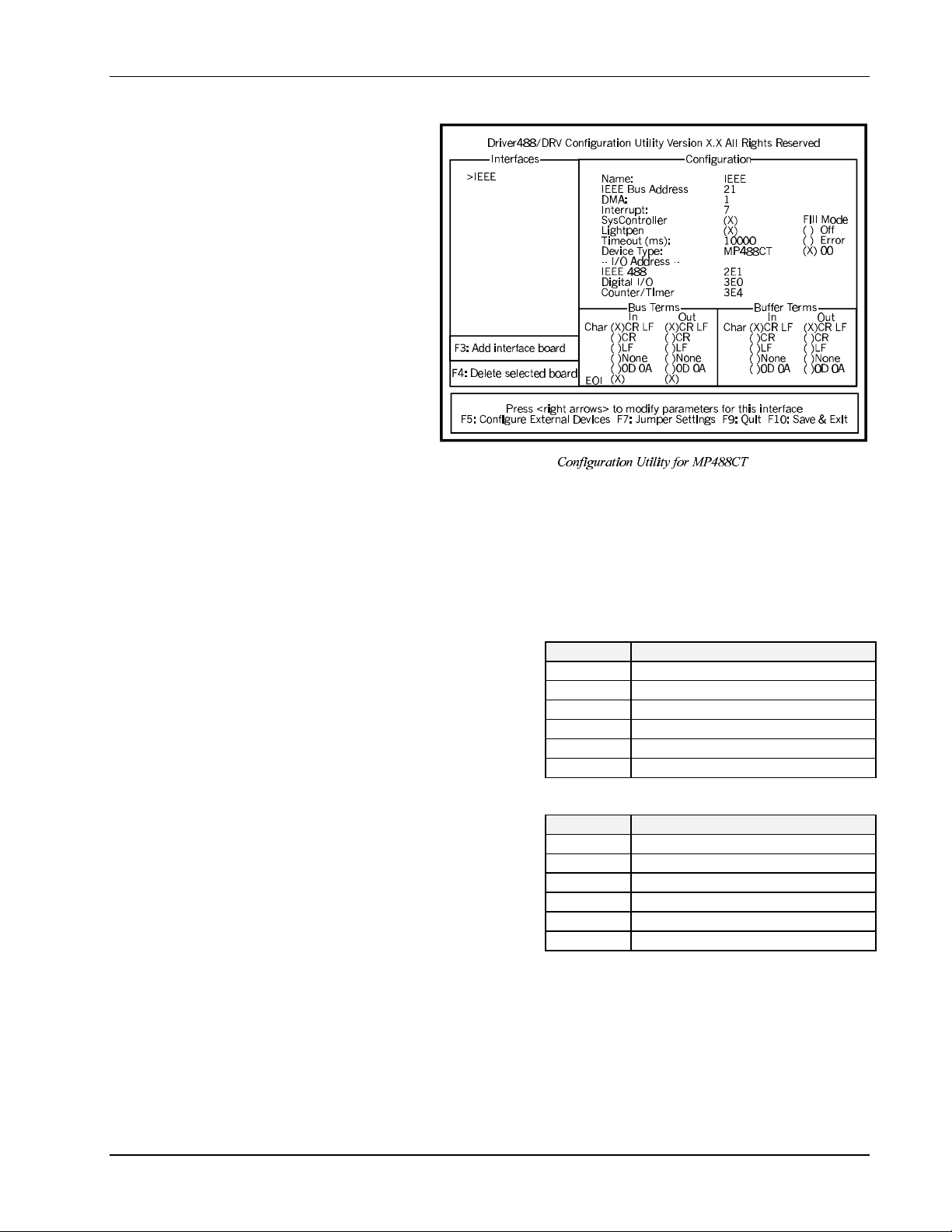
II. SOFTWARE GUIDES - 8. Driver488/DRV 8B. Installation & Configuration
Configuration of IEEE 488 Interfaces
The Driver488/DRV supports
two types of interfaces: IEEE
and Serial (COM). The
following Driver488/DRV
figure displays the configuration
screen of an MP488CT
IEEE 488.2 interface.
To add another IEEE interface,
select <F3>. If you will be
using more than one interface,
refer to the final topic “Multiple
Interface Management” in this
Sub-Chapter.
Once an interface is selected,
the fields and default entries
which display in the
configuration window depend
on the device type specified.
The configuration parameters of
the interface, are as follows:
Configuration Parameters
• Name: This field is a descriptive instrument name which is manually assigned by the user. This
must be a unique name. Typically, IEEE or COM is used.
• IEEE Bus Address: This is the setting for the IEEE bus address of the board. It will be checked
against all the instruments on the bus for conflicts. It must be a valid address from 0 to 30.
• • DMA: A direct memory access (DMA)
channel can be specified for use by the I/O
interface card. If DMA is to be used, select
a channel as per the hardware setting. If no
DMA is to be used, select NONE. The
NB488 does not support DMA, so the DMA
field will not display if this device type is
used. Valid settings are shown in the table.
• Interrupt: A hardware interrupt level can
be specified to improve the efficiency of the
I/O adapter control and communication
using Driver488/DRV. For DMA operation
or any use of OnEvent and Arm functions,
an interrupt level must be selected. Boards
may share the same interrupt level. If no
interrupt level is to be used, select NONE.
Valid interrupt levels depend on the type of
interface. Possible settings are shown in the table.
I/O Board Specified DMA Channel
GP488B 1, 2, 3 or none
AT488 1, 2, 3, 5, 6, 7 or none
MP488 1, 2, 3, 5, 6, 7 or none
MP488CT 1, 2, 3, 5, 6, 7 or none
NB488 Not applicable
CARD488 Not applicable
I/O Board Specified Interrupt Level
GP488B levels 2-7 or none
AT488 levels 3-7, 9-12, 14-15 or none
MP488 levels 3-7, 9-12, 14-15 or none
MP488CT levels 3-7, 9-12, 14-15 or none
NB488 level 7 for LPT1, level 5 for LPT2
CARD488 levels 3-7, 9-12, 14-15 or none
• SysController: This field determines whether or not the IEEE 488 interface card is to be the
System Controller. The System Controller has ultimate control of the IEEE 488 bus, and the
ability of asserting the interface clear (IFC) and remote enable (REN) signals. Each IEEE 488 bus
can have only one System Controller. If the board is a peripheral, it may still take control of the
IEEE 488 bus if the Active Controller passes control to the board. The board may then control the
bus and, when it is done, pass control back to the System Controller or another computer, which
then becomes the active controller. If the board will be operating in Peripheral mode (not System
Controller), select NO in this field.
Personal488 User’s Manual, Rev. 3.0 II-39
Page 56
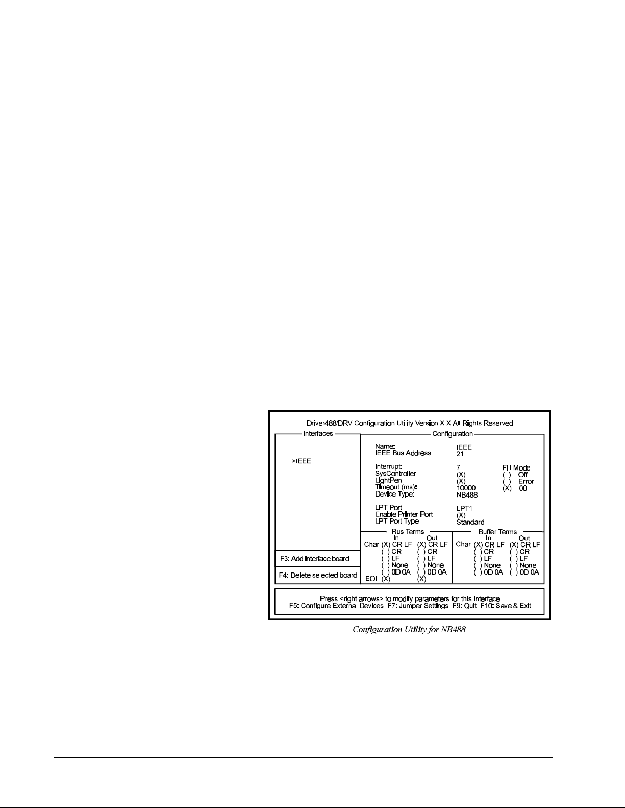
8B. Installation & Configuration II. SOFTWARE GUIDES - 8. Driver488/DRV
• LightPen: This field determines whether the LIGHT PEN command is to be used. If selected, it
will disable the detection of interrupts via setting the light pen status. The default is light pen
interrupt enabled.
• Timeout (ms): The time out period is the amount of time that data transfers wait before assuming
that the device does not transfer data. If the time out period elapses while waiting to transfer data,
an error signal occurs. This field is the default timeout for any bus request or action, measured in
milliseconds. If no timeout is desired, the value may be set to zero.
• Device Type: This field specifies the type of board or module (such as GP488, MP488CT or
NB488) represented by the IEEE device name selected.
I/O Address
• IEEE 488: This field is the I/O base address which sets the addresses used by the computer to
communicate with the IEEE interface hardware on the board. The address is specified in
hexadecimal and can be 02E1, 22E1, 42E1 or 62E1.
Note: This field does not apply to the NB488. Instead, the NB488 uses the I/O address of the data
register (the first register) of the LPT port interface, typically 0x0378.
• Digital I/O: This field is the base address of the Digital I/O registers. It is only applicable for
MP488 and MP488CT boards. Note that the Digital I/O SCPI communication parameters are
configured as an external device. Refer to the “Section I: Hardware Guides” for more information.
• Counter/Timer: This field is the base address of the Counter/Timer registers. It is only
applicable for MP488CT boards. Note the Counter/Timer SCPI communication parameters are
configured as an external device. Refer to the “Section I: Hardware Guides” for more information.
• Bus Terminators: The IEEE 488 bus terminators specify the characters and/or end-or-identify
(EOI) signal that is to be appended to data that is sent to the external device, or mark the end of
data that is received from the external device.
This second Driver488/DRV
configuration example displays
an IEEE interface with the
NB488 interface module
specified. This screen
resembles the previous IEEE
interface example with the
exception of 3 different
configuration parameters which
are described below.
Configuration Parameters
• LPT Port: The LPT port
is the external parallel port
to be connected to the
NB488. Valid selections
are: LPT1, LPT2 or LPT3.
This field takes the place
of the I/O Address field.
• Enable Printer Port:
Because most laptop and notebook PCs provide only one LPT port, the NB488 offers LPT passthrough for simultaneous IEEE 488 instrument control and printer operation. If this option is
selected, a printer connected to the NB488 will operate as if it were connected directly to the LPT
port. If not enabled, then the printer will not operate when the NB488 is active. The disadvantage
of pass-through printer support is that it makes communications with the NB488 about 20%
slower.
II-40 Personal488 User’s Manual, Rev. 3.0
Page 57
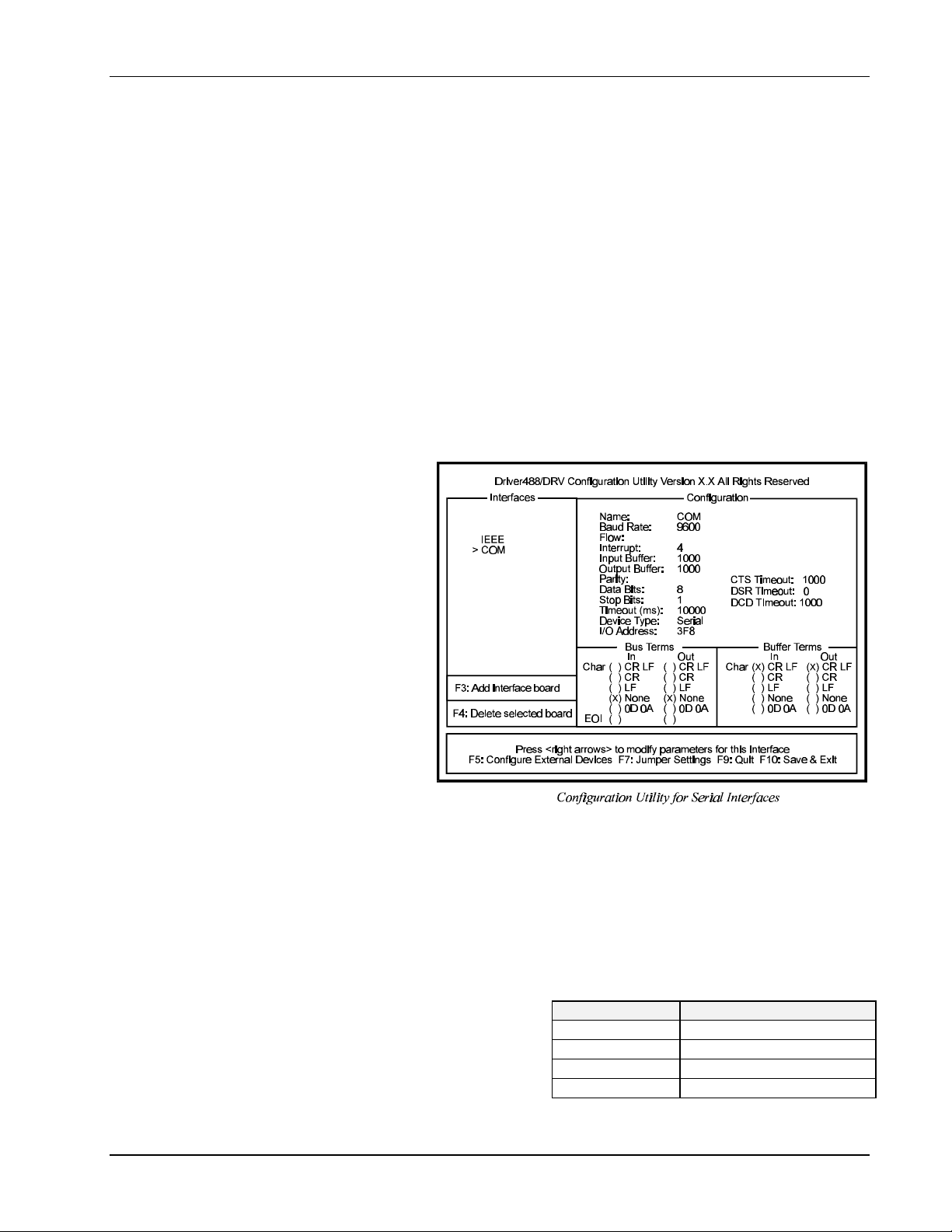
II. SOFTWARE GUIDES - 8. Driver488/DRV 8B. Installation & Configuration
• LPT Port Type: This field is used to specify whether the LPT port is a standard IBM
PC/XT/AT/PS/2 compatible port. Valid options are: Standard or 4-bit. The slower 4-bit option is
provided for those computers which do not fully implement the IBM standard printer port. These
computers can only read 4 bits at a time from the NB488 making communication with the NB488
up to 30% slower.
A test program has been provided with NB488 to help identify the user’s LPT port type. Once the
NB488 is installed, type: NBTEST.EXE. This program will determine if your computer can
communicate with the NB488 and what type of LPT port is installed (Standard or 4-bit).
It is important to note there are four different versions of the NB488 driver. The CONFIG utility
determines which is to be used based on the user-defined parameters. If both pass-through printer
support and the 4-bit LPT port support are selected, then the communication with the IEEE 488 bit
may be slowed as much as 40% compared with the fastest case in which neither option is selected.
The actual performance will very depending on the exact type and speed of the computer used.
To save your changes to disk, press <F10>, or to exit without making any changes, press <F9>. All
changes will be saved in the directory where you installed Driver488/DRV. If at any time you wish to
alter your Driver488/DRV configuration, simply rerun CONFIG.
Configuration of Serial Interfaces
The following Driver488/DRV
screen displays the
configuration of a Serial
(COM) interface.
To add another serial interface,
select <F3>. The following
serial interface parameters are
available for modification.
Configuration Parameters
• Name: This field is a
descriptive instrument
name which is manually
assigned. This must be a
unique name.
• Baud Rate: The
allowable Data Rates range
from 75 to 115.2K and all
standard rates therein.
This includes: 75, 110, 150, 300, 600, 1200, 1800, 2400, 4800, 9600, 19.2K, 38.4K, 57.6K, and
115.2K. Slower processors may have difficulty at the higher data rates because of the amount of
processing required for terminator, end of buffer, and fill processing.
• Flow: X-ON/X-OFF is supported. With this configured, Driver488/DRV scans incoming
characters for an X-OFF character. Once it is received, no more characters are transmitted until an
X-ON character is received. The driver also issues an X-OFF to ask the attached device to stop
sending when its internal buffer becomes three-quarters full and issues an X-ON when its buffer has
emptied to one-quarter full.
• Interrupt: A hardware interrupt level can be
specified to improve the efficiency of the I/O
adapter control and communication using
Driver488/DRV. For any use of OnEvent
and Arm functions, an interrupt level must be
selected. If no interrupt level is to be used,
select NONE. Valid interrupt levels depend
on the device type.
Personal488 User’s Manual, Rev. 3.0 II-41
I/O Comm. Typical Interrupt Level
COM1 typically level 4
COM2 typically level 3
COM3 typically level 4 or 5
COM4 typically level 2 or 3
Page 58

8B. Installation & Configuration II. SOFTWARE GUIDES - 8. Driver488/DRV
• Input Buffer: This field is used to enter the buffer sizes for I/O.
• Output Buffer: This field is used to enter the buffer sizes for I/O.
• Parity: Parity can be EVEN, ODD, NONE, MARK, or SPACE.
• CTS Timeout: The driver supports 3 hardware handshake lines: Data Carrier Detect (DCD), Data
Set Ready (DSR), and Clear To Send (CTS). Each line can be individually designated to be
ignored, used with no specified timeout, or used with a selected timeout. The timeout is selected
by specifying the number of milliseconds to wait for the indicated condition to become satisfied.
• Data Bits: Data formats from 5 though 8 Data Bits are supported.
• DSR Timeout: The driver supports 3 hardware handshake lines: Data Carrier Detect (DCD), Data
Set Ready (DSR), and Clear To Send (CTS). Each line can be individually designated to be
ignored, used with no specified timeout, or used with a selected timeout. The timeout is selected
by specifying the number of milliseconds to wait for the indicated condition to become satisfied.
• Stop Bits: With 6, 7, or 8 Data Bits specified, either 1 or 2 Stop Bits are allowed. With 5 Data
Bits specified, 1 or 1.5 Stop Bits may be selected.
• DCD Timeout: The driver supports 3 hardware handshake lines: Data Carrier Detect (DCD), Data
Set Ready (DSR), and Clear To Send (CTS). Each line can be individually designated to be
ignored, used with no specified timeout, or used with a selected timeout. The timeout is selected
by specifying the number of milliseconds to wait for the indicated condition to become satisfied.
• Timeout (ms): The time out period is the amount of time that data transfers wait before assuming
that the device does not transfer data. If the time out period elapses while waiting to transfer data,
an error signal occurs. This field is the default timeout for any bus request or action, measured in
milliseconds. If no timeout is desired, the value may be set to zero.
• Device Type: This field specifies the type of device represented by the serial external device
name selected.
• I/O Address: The I/O Address is the
computer bus address for the board. It is set to
default values, as listed in the table, during the
initial installation. These values can be
changed, however, using the default address
values is recommended. Any conflict will be
noted by a pop up help screen.
• Bus Terminators: The bus terminators specify the characters to be appended to data that is sent
to the external device, or mark the end of data that is received from the external device.
I/O Comm. Default Address Values
Configuration of IEEE 488 External Devices
Within your IEEE 488.2 application program, devices on the bus may be accessed by name. These
names must be created and configured with the CONFIG program, after you have configured your
interfaces.
The following figure displays the configuration screen of an external device named DMM195. When
configuring an IEEE interface, this screen can be accessed by selecting <F5> Configure External
Devices.
To add additional devices, use <F3>. Note this external device screen is also used to configure
MP488CT Digital I/O (DIGIO) and Counter/Timers (TIMER).
The following parameters are available for modification.
COM1 typically address 3F8
COM2 typically address 2F8
COM3 typically address 3E8
COM4 typically address 2E8
II-42 Personal488 User’s Manual, Rev. 3.0
Page 59
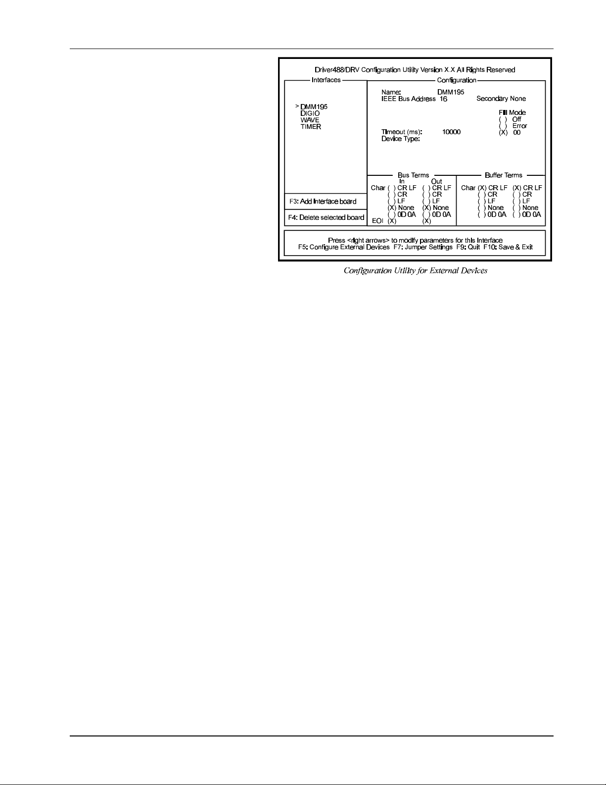
II. SOFTWARE GUIDES - 8. Driver488/DRV 8B. Installation & Configuration
Configuration Parameters
• Name: External device
names are user defined
names which are used to
convey the configuration
information about each
device, from the
initialization file to the
application program. Each
external device must have
a name to identify its
configuration to
Driver488/DRV. The
name can then be used to
obtain a handle to that
device which will be used
by all of the
Driver488/DRV
commands. External
device names consist of 1
to 6 characters, and the first character must be a letter. The remaining characters may be letters,
numbers, or underscores ( _ ). External device names are case insensitive; upper and lower case
letters are equivalent. ADC is the same device as adc.
• IEEE Bus Address: This is the setting for the IEEE 488 bus address of the device. It will be
checked against all the devices on the bus for conflicts. The IEEE 488 bus address consists of a
primary address from 00 to 31, and an optional secondary address from 00 to 31 or “NONE”.
• Timeout (ms): The time out period is the amount of time that data transfers wait before assuming
that the device does not transfer data. If the time out period elapses while waiting to transfer data,
an error signal occurs. This field is the default timeout for any bus request or action, measured in
milliseconds. If no timeout is desired, the value may be set to zero.
• Device Type: This field specifies the type of device represented by the external device name
selected.
• Bus Terminators: The IEEE 488 bus terminators specify the character(s) and/or end-or-identify
(EOI) signal that is to be appended to data that is sent to the external device, or mark the end of
data that is received from the external device.
Note: Because secondary addresses and bus terminators are specified for each external device name,
it may be useful to have several different external devices defined for a single IEEE 488 bus
device. For example, separate names would be used to communicate with different secondary
addresses within a device. Also, different names might be used for communication of
command and status strings (terminated by carriage return/line feed) and for communication
of binary data (terminated by EOI).
Note: If installation or configuration problems exist, refer to “Section IV: Troubleshooting.”
To save your changes to disk, press <F10>. All changes will be saved in the directory where you
installed Driver488/DRV. If at any time you wish to alter your Driver488/DRV configuration, simply
rerun CONFIG.
Multiple Interface Management
When designing a complex data acquisition system, it might be necessary to have more than one
IEEE 488 bus interface controlled by the computer. Typical instances include: A system with more
than 15 devices, the use of distributed control or the simultaneous operation of multiple transactions.
Personal488 User’s Manual, Rev. 3.0 II-43
Page 60

8B. Installation & Configuration II. SOFTWARE GUIDES - 8. Driver488/DRV
System With More Than 15 Devices
The IEEE 488 electrical specification limits the number of devices on a single bus (including the
controller) to 15. While a bus expander, such as the Expander488, can increase that limit to 28,
complex systems may require two or more IEEE 488 buses and have more controllers.
In this case, two or more interfaces would be used, each configured as a System Controller. Because
they are attached to completely separate buses, the two interfaces do not affect each other. They can
have the same IEEE 488 bus address, and the addresses of the devices on one bus may be the same as
the addresses of the devices on the other bus.
Use of Distributed Control
Two or more IEEE 488 buses can also be useful when they have different functions. For example, a
computer might use one bus as a System Controller to control instruments, while using another bus as a
Peripheral, to communicate with another computer.
Simultaneous Operation of Multiple Transactions
Another use of two IEEE 488 buses is to allow simultaneous operation of two separate transactions.
Some instruments, such as spectrum analyzers, have the ability to send their results, through the
IEEE 488 bus, directly to a printer or a plotter. Such an instrument, along with a printer or plotter,
would be attached to one interface, while other devices would be attached to another IEEE 488
interface. The computer could configure the spectrum analyzer to plot its results and then pass control
to it, allowing it to control the printer or plotter. Meanwhile, the computer would be using the other
bus to control other equipment.
To allow such complex systems, Driver488/DRV supports as many as four interfaces on a single
computer. The CONFIG program helps you to configure multiple interfaces and notifies you of possible
conflicts.
The examples in this manual assume, for the most part, that only one board is installed in the system,
and that it is accessed through the three device names given above for the first board. If multiple
interfaces are installed, then they are accessed in just the same manner as the first board, except that
different device names, as given above, are used. If, for example, two interfaces are installed, then a
BASIC program to use them might be:
100 OPEN “\DEV\IEEEIN” FOR INPUT AS #1
110 OPEN “\DEV\IEEEOUT” FOR OUTPUT AS #2
120 OPEN “\DEV\IEEEIN2" FOR INPUT AS #3
130 OPEN “\DEV\IEEEOUT2" FOR OUTPUT AS #4
140 PRINT#2,"OUTPUT 10;R0X"
150 PRINT#4,"OUTPUT 10;R1X"
where line 140 sends R0X to device 10 on the IEEE 488 bus controlled by board 1, and line 150 send
R1X to device 10 on the second IEEE 488 bus. Because they are on two physically different IEEE 488
buses, there is no confusion as to which device 10 is being accessed.
Note: If installation or configuration problems exist, refer to “Section IV: Troubleshooting.”
II-44 Personal488 User’s Manual, Rev. 3.0
Page 61
II. SOFTWARE GUIDES - 8. Driver488/DRV 8C. External Device Interfacing
8C. External Device Interfacing
Topics
• • Introduction .................................................................................... II-45
• • Character Command Language (CCL) ...................................... II-45
• • DOS Devices..................................................................................... II-46
• • Configuration of Named Devices ................................................ II-46
• • Use of External Devices ................................................................ II-47
• • Direct I/O with DOS Devices........................................................ II-47
• • Extensions For Multiple Interfaces............................................ II-48
Duplicate Device Names ............................................................................... II-48
Access of Multiple Interfaces .......................................................................II-48
Example........................................................................................................... II-49
Introduction
This Sub-Chapter is a technical review of external device interfacing. It contains information on how
to use external devices, DOS devices and multiple interfaces.
Driver488/DRV controls I/O interfaces and their attached external devices. In turn, Driver488/DRV is
controlled by one of two access methods: the Character Command Language (CCL), and direct DOS
I/O devices.
Driver488/DRV communicates directly with I/O interfaces, such as an IEEE 488 interface board and a
serial (RS-232) port. More than one I/O interface may reside on a single plug-in board. For example,
an RS-232 board often contains two or four functionally separate I/O interfaces, one for each port. The
GP488B board contains the IEEE 488 I/O interface; and an MP488CT board contains an IEEE 488
interface, a digital I/O interface, and a counter/timer I/O interface.
I/O interfaces connect to external devices such as: digitizers, multimeters, plotters, and oscilloscopes
(IEEE 488 interface); and serial devices such as printers, plotters, and modems (serial RS-232 port).
Driver488/DRV allows direct control of IEEE 488 external devices, but it does not support other
external devices such as an RS-232 plotter. Such devices are supported by directly controlling the I/O
interface (serial port).
Driver488/DRV is controlled by sending data and commands, and receiving responses and status by
one of two access methods: the Character Command Language, and Direct DOS I/O devices. These
methods, also known as Application Program Interfaces or APIs, are available to connect the
application (user’s) program to Driver488/DRV.
Character Command Language (CCL)
The Character Command Language (CCL) API is a type of DOS device driver that can control and
communicate with Driver488/DRV. A DOS device driver is a special type of program that appears to
the user’s program as a file that can be written to and read from like any disk file, but that does not
actually read and write the disk. For example, the DOS command:
COPY FILE.LST LPT1
copies the disk file FILE.LST to the device driver LPT1 which prints FILE.LST. There is no file
named LPT1; the LPT1 device driver program has the responsibility for communicating with the
printer. The COPY command can write to LPT1 just like an ordinary file, but DOS knows LPT1 is only
a device driver and allows it to process the data.
Personal488 User’s Manual, Rev. 3.0 II-45
Page 62

8C. External Device Interfacing II. SOFTWARE GUIDES - 8. Driver488/DRV
The Character Command Language is a device driver that writes commands to, and reads responses
from, Driver488/DRV. To use the Character Command Language, the application program opens a file
with a special name, such as: “\DEV\IEEE”, and uses standard DOS file I/O commands to
communicate with the Character Command Language device driver. Since the CCL is a device driver,
standard DOS commands such as: TYPE and COPY may be used to communicate with Driver488/DRV
via the CCL.
DOS Devices
Driver488/DRV may also be controlled by using DOS Devices. A DOS Device is a special type of
DOS device driver that uses Driver488/DRV to communicate with a single External Device.
Remember that, as a DOS device driver, a DOS Device may be written to and read from, like any disk
file. When writing data to a DOS Device, the device driver commands Driver488/DRV to send the
data to the corresponding External Device. Similarly, when reading from the DOS Device, the device
driver commands Driver488/DRV to read data from the External Device.
Driver488/DRV allows DOS Devices to be created that refer to specific External Devices, just as LPT1
refers to the printer. For example, if an IEEE 488 plotter were configured as a DOS Device named
PLOTDD (DD for DOS Device), then we could use COPY to send a plot file to it:
COPY PLOTFILE.PLT PLOTDD
Configuration of Named Devices
External Devices and DOS Devices are most easily configured by using CONFIG. The device names,
terminators, time out period, and bus addresses may be entered into CONFIG which then writes a
configuration file containing the device configuration information. This configuration file is
automatically read when Driver488/DRV loads to install the configured devices.
Every device to be accessed by Driver488/DRV must have a valid device name. Driver488/DRV
comes with several device and interface names preconfigured for use. Among those already configured
for the GP488B board, for example, are: IEEE and COM1. You can configure up to 50 external devices
for the IEEE 488 bus.
It is also possible to configure new named devices by using the Driver488/DRV command
MAKE DEVICE. The MAKE DEVICE command creates a temporary device that is an identical copy of
an already existing Driver488/DRV device. The new device has default configuration settings identical
to those of the existing device. The new device can then be reconfigured by calling the proper
functions, such as BUS ADDRESS, INT LEVEL, and TIME OUT. When Driver488/DRV is closed, the
new device is forgotten unless the KEEP DEVICE command is used to make it permanent.
The following code illustrates how the Character Command Language API version of the MAKE
DEVICE command could be used to configure several new named devices:
100 PRINT#1,"MAKE DEVICE DMM =ADC"
110 PRINT#1,"BUSADDRESS 16"
120 PRINT#1,"TERM CR LF EOI"
200 PRINT#1,"MAKE DEVICE SCOPECMD =ADC"
210 PRINT#1,"BUSADDRESS 1200"
220 PRINT#1,"TERM LF"
300 PRINT#1,"MAKE DEVICE SCOPE =ADC"
310 PRINT#1,"BUSADDRESS 1201"
320 PRINT#1,"TERM EOI"
Lines 100-120 of the above example define an external device named DMM (digital multi-meter) as
device 16 with bus terminators of carriage-return line-feed (CR LF) and EOI. Lines 200-220 configure
an oscilloscope command channel to use line-feed as its IEEE 488 bus terminator at a primary address
of 12 and secondary address 00. Lines 300-320 configure the oscilloscope data channel to use EOI
only as the bus terminator so that it can transfer binary data to its address of 1201: primary address 12,
secondary address 01.
External Devices and DOS Devices defined at installation time are permanent. Their definitions last
until they are explicitly removed or until the computer is restarted. Devices defined after installation
II-46 Personal488 User’s Manual, Rev. 3.0
Page 63

II. SOFTWARE GUIDES - 8. Driver488/DRV 8C. External Device Interfacing
are normally temporary. They are forgotten as soon as the program finishes. The KEEP DEVICE and
KEEP DOS NAME commands can be used to make these devices permanent. The REMOVE DEVICE and
REMOVE DOS NAME commands remove the definitions of devices even if they are permanent. These
commands are described in further detail in the “Section III: Command Reference” of this manual.
Use of External Devices
Once we have configured the external devices, we can refer to devices by name. For example, using
the Character Command Language, the following program allows Driver488/DRV to communicate
with a digital multimeter:
200 PRINT#1,"CLEAR DMM"
210 PRINT#1,"OUTPUT DMM;VDC"
220 PRINT#1,"ENTER DMM"
230 INPUT#2,VOLTAGE
300 PRINT#1,"TRIGGER SCOPECMD"
320 PRINT#1,"ENTER SCOPE #1000 BUFFER 11";DS%;":";VARPTR(ARRAY)
In these commands we CLEAR the DMM, configure it for DC volts, take a reading and store it in the
variable VOLTAGE. Next, we TRIGGER the SCOPE at its command address and then read from its binary
data channel into an array. While these commands are hypothetical, they show how device names can
be used wherever a device address is allowed.
As mentioned above, named devices have another advantage: they automatically use the correct bus
terminators and time out. When a named device is defined, it is assigned bus terminators and a time
out period. When communication with that named device occurs, Driver488/DRV uses these
terminators and time out period automatically. Thus TERM statements are not needed to reconfigure the
bus terminators for devices that cannot use the default terminators (which are usually carriage-return
line-feed EOI). It is still possible to override the automatic bus terminators by explicitly specifying the
terminators in an ENTER or OUTPUT command. For more information, see the ENTER, OUTPUT, and
TERM commands described in “Section III: Command References.”
Direct I/O with DOS Devices
DOS Devices can be opened as files for direct communication. For example, we can configure two
names to refer to a plotter with an IEEE 488 bus address of 05:
400 PRINT #1,"MAKE DEVICE PLOTTER BUSADDRESS 05"
410 PRINT #1,"MAKE DOS NAME PLOT=PLOTTER"
420 PRINT #1,"MAKE DOS NAME PLOTIN=PLOTTER"
Then we can open them, one for input and one for output:
430 OPEN “PLOT” FOR OUTPUT AS #3
440 OPEN “PLOTIN” FOR INPUT AS #4
Two different names are used to communicate with the plotter because, in BASIC, the same file cannot
be used for both input and output. In other languages, it might be possible to use the same file (with the
same device name) for both input and output. Also note that BASIC normally has a limit of 3 open
files. To open more than 3 files (as in this example; 2 for Driver488/DRV commands, and 2 for the
plotter), BASIC must be started with the parameter /F:n (where n is the number of files). See your
BASIC manual for more details.
For clarity, the DOS Device names are not the same as External Device names. In normal use, one of
the DOS Device names might be chosen to be the same as an External Device name to show that they
communicate with the same External Device. Of course, the two DOS Device names must be different.
Once the files are opened, we can communicate PRINT commands to the plotter and INPUT responses
from the plotter without using the Driver488/DRV OUTPUT or ENTER commands. When a named
device is used as a file, the OUTPUT and ENTER commands occur automatically.
500 PRINT#3,"IN; SP1; PA1000,1000;" ‘Send plot commands
510 PRINT#3,"OE;" ‘Request plotter status
520 INPUT#4,ST$ ‘Read plotter status
Personal488 User’s Manual, Rev. 3.0 II-47
Page 64

8C. External Device Interfacing II. SOFTWARE GUIDES - 8. Driver488/DRV
530 PRINT ST$ ‘and display it
Once a named device is configured, standard DOS commands may be used to transfer data to that
device. For example:
COPY PLOTFILE.DAT PLOT
copies the plot data file PLOTFILE.DAT to the IEEE 488 bus plotter.
CAUTION
Because named devices can be used as files, some care must be taken so that they do not interfere
with other file or device names in the system:
1. Device names should not be the same as the primary name (the part before the period) of any
existing files or directories. For example, if you define a device with the name “BASIC”,
then you cannot use the program “BASIC.EXE”, and if you name a device “IEEE 488", then
you cannot access the Driver488/DRV subdirectory.
2. Device names should not be one of the standard DOS device names: COM, AUX, CON, LPT,
or PRN. This could interfere with normal DOS operation.
3. Device names should normally not be duplicated. If duplicate device names are used, only
the last one of them installed is accessible. To avoid confusion, duplicate device names are
not recommended.
With the considerations noted in the above warning, External Devices and DOS Devices make
Driver488/DRV significantly easier to use. External Devices allow IEEE 488 bus devices to be
referenced symbolically, by a name, rather than by their bus address. They also automatically use the
appropriate IEEE 488 bus terminators and time out period. Finally, it is possible to communicate
directly with DOS Devices just as you would communicate with any file.
Extensions For Multiple Interfaces
Driver488/DRV allows the simultaneous control of multiple interfaces each with several attached
devices. To avoid confusion, external devices may be referred to by their “full name” which consists of
two parts. The “first name” is the hardware interface name, followed by a colon separator ( : ). The
“last name” is the external device name on that interface. For example, the “full name” of DMM might
be IEEE:DMM.
Duplicate Device Names
Duplicate device names are most often used in systems that consist of several identical sets of
equipment. For example, a test set might consist of a signal generator and an oscilloscope. If three test
sets were controlled by a single computer using three separate IEEE 488 interfaces, then each signal
generator and each oscilloscope might be given the same name and the program would specify which
test set to use by opening the correct interface (OPEN“IEEE” for one, OPEN“IEEE2" for the other), or
by using the interface names when communicating with the devices (”IEEE:GENERATOR" for one and
“IEEE2:GENERATOR” for the other.)
Unique names are appropriate when the devices work together, even if more than one interface is used.
If two different oscilloscopes, on two different interfaces are used as part of the same system, then they
would each be given a name appropriate to its function. This avoids confusion and eliminates the need
to specify the interface when opening the devices.
Access of Multiple Interfaces
If the computer only has one IEEE 488 interface, then there is no confusion, for every external device
is known to be on that interface. However, if the computer has more than one IEEE 488 interface, then
rules apply when using the Character Command Language:
II-48 Personal488 User’s Manual, Rev. 3.0
Page 65
II. SOFTWARE GUIDES - 8. Driver488/DRV 8C. External Device Interfacing
1. If the external device name is defined on the current hardware interface, then that interface is used
to communicate with that device. The current hardware interface is the one that was opened to
communicate with Driver488/DRV. This would be IEEE for the first IEEE 488 interface, IEEE2
for the second, etc.
2. If the name is defined on another hardware interface, that other interface is used to communicate
with that device.
3. If the name is defined on more than one other interface (and not on the current interface) then one
of those interfaces is used. The choice of which particular interface is not defined.
4. In order to specify the interface to use, the interface name may be prefixed with a colon to the
device name. For example, IEEE2:DMM refers to the digital multimeter attached to interface
IEEE2. If the specified device does not exist on the specified interface, then an error occurs.
Example
Assume there are three IEEE 488 interfaces: IEEE, IEEE2, and IEEE3 controlling multiple devices:
SCOPE (on IEEE), DA (on IEEE2) and DA (on IEEE3). Since there are two external devices, both
named DA, their full name must be used to specify them.
After opening the interfaces with the following command lines:
OPEN “IEEE” AS #1
OPEN “IEEE2" AS #2
OPEN “IEEE3" AS #3
we can communicate with the external devices, according to the four rules above.
PRINT #1,"OUTPUT SCOPE;..."
PRINT #3,"OUTPUT SCOPE;..."
PRINT #1,"OUTPUT DA;..."
PRINT #1,"OUTPUT IEEE2:DA;..."
PRINT #1,"OUTPUT IEEE2:SCOPE;..."
8D. Getting Started
• • Introduction .................................................................................... II-49
• • Keyboard Controller Program .................................................... II-50
• • Direct Control from DOS Using CCL ......................................... II-51
Introduction
Once Driver488/DRV has been installed in your system, it is ready to begin controlling IEEE 488 bus
devices. This Sub-Chapter describes methods of controlling the bus directly from the keyboard. Other
Sub-Chapters in this Chapter develop short programs, in various languages, to control a Keithley
Instruments Model 195 digital multimeter. The techniques used in these programs are quite general,
and apply to the control of most instruments.
SCOPE on IEEE. See Rule 1
SCOPE on IEEE (not IEEE2). See Rule 2
DA on IEEE2 or IEEE3 (not specified). See Rule 3
DA on IEEE2. See Rule 4
ERROR (not IEEE:SCOPE). See Rule 4
Topics
It is not necessary to write programs to control IEEE 488 bus devices using Driver488/DRV. Instead,
using the Character Command Language Application Program Interface (CCL API), commands to the
bus may be sent directly from the keyboard, with responses displayed on the screen or sent to a file.
The Keyboard Controller program provides this capability, as do the standard MS-DOS commands.
Personal488 User’s Manual, Rev. 3.0 II-49
Page 66

8D. Getting Started II. SOFTWARE GUIDES - 8. Driver488/DRV
Keyboard Controller Program
The program KBC.EXE is a utility program that allows you to enter Driver488/DRV commands from
the keyboard and see what effect they have. When KBC is run, it displays an IEEE> prompt and waits
for a command to be entered from the keyboard. When the <Enter> key is pressed, KBC sends the
command to Driver488/DRV and displays any response or error messages that occur. This allows you
to test the various Driver488/DRV commands and their effects on your instruments without having to
write a program. A dialog with KBC might be:
First, we can use the HELLO command to display the Driver488/DRV revision identification:
IEEE> HELLO <Enter>
Driver488 Revision X.X ©199X IOtech, Inc.
Then check the Driver488/DRV status:
IEEE> STATUS <Enter>
CS21 1 I000 000 T0 C0 P0 OK
The following indicators describe each component of the Driver488/DRV status:
Indicator Driver488/DRV Status
C
S
21
1
I
0
0
0
000
T0
C0
P0
OK
It is in the Controller state.
It is the System Controller.
The value of its IEEE 488 bus address.
An Address Change has occurred.
It is idle (neither a talker nor a listener).
There is no ByteIn available.
It is not ready to send a ByteOut.
Service Request (SRQ) is not asserted.
There is no outstanding error.
It has not received a bus device TRIGGER command (only applicable in the Peripheral
mode).
It has not received a CLEAR command (only applicable in the Peripheral mode).
No CONTINUE transfer is in progress.
The error message is “OK”.
Next, take a reading from IEEE 488 bus device 16:
IEEE> ENTER 16 <Enter>
NDCV=035.679E-3
Now, list the commands that have been executed so far and re-execute the ENTER command:
IEEE> .L <Enter>
3 HELLO
2 STATUS
1 ENTER 16
IEEE .1 <Enter>
IEEE> ENTER 16 <Enter>
NDCV+032.340E-3
Notice that the .L and .1 commands are not Driver488/DRV commands. Instead, they are supplied by
the KBC program. The .L command is used to show a list of the previously entered commands. KBC
keeps the last 20 commands in this list. Any of these commands can be reentered by typing a period
followed by the number of that command. For example, the .1 command reenters the last command
that was entered. The user may then edit this command, or may just press <Enter> re-executing the
command.
II-50 Personal488 User’s Manual, Rev. 3.0
Page 67
II. SOFTWARE GUIDES - 8. Driver488/DRV 8D. Getting Started
Finally, EXIT causes KBC to terminate:
IEEE> EXIT <Enter>
As already mentioned, KBC obeys the standard DOS editing keys. In using these editing keys, the
previous command is used as a template. Characters from the template are copied into the current
command line under control of the editing keys. These editing keys, coupled with the ability to retrieve
previous commands, greatly ease the task of trying various Driver488/DRV commands.
The editing keys and their actions are:
Editing Key Editing Function
<F1> or <àà>
<F2>char
Copies one character from the template to the command line.
Copies characters from the template to the command line up to the character
specified.
<F3>
<F4>char
Copies all remaining characters from the template to the command line.
Skips over (does not copy) characters from the template up to the character
specified.
<F5>
<Del>
<Ins>
Replaces the template with the current command line.
Skips over (does not copy) one character in the template.
Toggles insert mode. When insert mode is off (the default) characters from
the template are skipped as characters are entered from the keyboard.
When insert mode is on, no characters in the template are skipped.
<Esc>
Clears the command line and leaves the template unchanged.
Direct Control from DOS Using CCL
Because Driver488/DRV is a standard MS-DOS device driver, any program that can read and write
characters to files can control the IEEE 488 bus. In particular, MS-DOS (and PC-DOS) provide
several commands that can communicate directly with Driver488/DRV. To begin communication, it is
helpful to turn on the Driver488/DRV automatic error display:
C:\> ECHO ERROR ON> IEEE <Enter>
and tell Driver488/DRV to end its responses with an end-of-file character (control-Z, ASCII 26):
C:\> ECHO FILL $26> IEEE <Enter>
Note the format of these commands: the DOS command ECHO, followed by the Driver488/DRV
command ERROR ON or FILL $26, which is redirected by the > to a file named IEEE. When ECHO
tries to write the command to IEEE, DOS notices that IEEE is the name of a device driver, not a file,
and so sends the command to the device driver which of course is Driver488/DRV.
Once the input terminator is initialized to the end-of-file character, DOS can be used to get responses
from Driver488/DRV and the attached IEEE 488 bus devices.
First, we can use the HELLO command to display the Driver488/DRV revision identification:
C:\> ECHO HELLO> IEEE <Enter>
C:\> TYPE IEEE <Enter>
Driver488 Revision X.X ©199X IOtech Inc.
Then check the Driver488/DRV status:
C:\> ECHO STATUS> IEEE <Enter>
C:\> TYPE IEEE <Enter>
CS21 1 I000 000 T0 C0 P0 OK
The following indicators describe each component of the Driver488/DRV status:
Personal488 User’s Manual, Rev. 3.0 II-51
Page 68

8D. Getting Started II. SOFTWARE GUIDES - 8. Driver488/DRV
Indicator Driver488/DRV Status
C
S
21
1
I
0
0
0
000
T0
It is in the Controller state.
It is the System Controller.
The value of its IEEE 488 bus address.
An Address Change has occurred.
It is idle (neither a talker nor a listener).
There is no ByteIn available.
It is not ready to send a ByteOut.
Service Request (SRQ) is not asserted.
There is no outstanding error.
It has not received a bus device TRIGGER command (only applicable in the Peripheral
mode).
C0
P0
OK
It has not received a CLEAR command (only applicable in the Peripheral mode).
No CONTINUE transfer is in progress.
The error message is “OK”.
Next, take a reading from IEEE 488 bus device 16:
C:\> ECHO ENTER 16> IEEE <Enter>
C:\> TYPE IEEE <Enter>
NDCV=035.679E-3
Now, if an IEEE 488 bus device name has been defined using the INSTALL program, that name can be
used to refer to the bus device. For example, assume that a Keithley Instruments Model 195 digital
multimeter has been given the name K195. The meter could be reset to its power-on conditions with a
CLEAR command:
C:\> ECHO CLEAR K195> IEEE <Enter>
To program the 195 for the 2 VDC range, send it the R3F0X command:
C:\> ECHO OUTPUT K195;R3F0X> IEEE <Enter>
This could also be achieved by sending the command directly to the device:
C:\> ECHO R3F0X> K195 <Enter>
To check the status of the 195, use the SERIAL POLL, or SPOLL command:
C:\> ECHO SPOLL K195> IEEE <Enter>
C:\> TYPE IEEE <Enter>
To display a reading from the 195, use the ENTER command:
C:\> ECHO ENTER K195> IEEE <Enter>
C:\> TYPE IEEE <Enter>
To view continuous readings from the 195, read directly from the K195 device:
C:\> TYPE K195 <Enter>
This causes readings to be taken from the 195 and displayed until <Ctrl-Break> is typed. Note that
<Ctrl-Break> may halt Driver488/DRV in the middle of a transaction, causing the first attempt at
another command to give a SEQUENCE ERROR. If this should occur, simply retry the last command.
It is also possible to save the bus device data into a file:
C:\> ECHO ENTER K195> IEEE <Enter>
C:\> TYPE IEEE> DATA <Enter>
C:\> ECHO ENTER FREQ> IEEE <Enter>
C:\> TYPE IEEE>> DATA <Enter>
The first two commands create a file named DATA that holds a reading from the 195. The next two
commands append a reading from the device FREQ to the data file. Note the use of the >> to indicate
append.
II-52 Personal488 User’s Manual, Rev. 3.0
Page 69
II. SOFTWARE GUIDES - 8. Driver488/DRV 8E. Microsoft C
8E. Microsoft C
Topics
• • Use of the Character Command Language............................... II-53
• • Initialization of the System.......................................................... II-53
• • Configuration of the 195 DMM .................................................... II-56
• • Taking Readings............................................................................. II-56
• • Buffer Transfers ............................................................................. II-56
• • Interrupt Handling ........................................................................ II-57
• • IEEEIO.C .......................................................................................... II-59
• • CRITERR.ASM (Microsoft C & Turbo C)................................... II-61
• • Sample Program ............................................................................. II-62
Use of the Character Command Language
In order to simplify programming Driver488/DRV with C, the following files are provided on the
Driver488/DRV program disk:
• IEEEIO.C: Communications routines for Driver488/DRV
• IEEEIO.H: Header file, contains declarations from IEEEIO.C
• IEEEDEMO.C: Example file showing use of fputs and fgets with Driver488/DRV (included
with Microsoft C only)
• CRITERR.ASM: Critical error handler assembly language source file (included with Microsoft C
and Turbo C only)
• CRITERR.OBJ: Object file produced from CRITERR.ASM (included with Microsoft C and Turbo
C only)
• CRITERR.H: Header file, contains declarations for using CRITERR.ASM
The actual demonstration program is contained in 195DEMO.C.
All files for Microsoft C are in the \MSC directory.
To execute the demonstration program, the files must be compiled and then linked. The following
DOS commands perform these steps:
C> msc 195demo;
C> msc ieeeio;
C> link 195demo ieeeio;
Finally, the demonstration program is run by typing 195DEMO <Enter>. Notice that the critical error
handler CRITERR.ASM is not required for the demonstration program. Its use is described later in
“CRITERR.ASM (Microsoft C & Turbo C),” one of the last topics in this Sub-Chapter.
The above command assumes that you have Microsoft C and that the files have been copied into the
appropriate directory for use with your C compiler. Notice that the program uses a small data model
because it uses less than 64K of code and data.
Initialization of the System
Any program using Driver488/DRV must first establish communications with the Driver488/DRV
software driver. In C, this is accomplished using the OPEN statement. Communication both to and
from Driver488/DRV is required. Thus, the file must be opened for both reading and writing (RDWR).
Personal488 User’s Manual, Rev. 3.0 II-53
Page 70

8E. Microsoft C II. SOFTWARE GUIDES - 8. Driver488/DRV
Also, in Microsoft C and Turbo C, the file must be opened in BINARY mode so that end-of-line
characters are not translated.
In Microsoft C and Turbo C, the file is opened with the following statement:
ieee=open(“ieee”,O_RDWR | O_BINARY);
which is part of the IEEEINIT function contained in IEEEIO.C. IEEEIO.C supplies several other
useful routines and definitions. These routines and definitions are described later in more detail in
“Interrupt Handling,” an upcoming topic in this Sub-Chapter.
In the above statement, the value returned by OPEN and placed into the integer variable IEEE, is either
the handle of the opened file, or -1 if some error has occurred. The IEEEINIT routine checks for this
error indication and returns a -1 if there has been such an error.
Of course, the file descriptor variable name IEEE may be changed as desired, but throughout this
manual and the program files, IEEE has been used. Once the file is opened, we can send commands
and receive responses from Driver488/DRV.
Normally, when DOS communicates with a file, it checks for special characters, such as control-Z
which can indicate end-of-file. When communicating with IEEE 488 devices, DOS’s checking would
interfere with the communication. The RAWMODE function prevents DOS from checkings for special
characters:
rawmode(ieee);
As an additional benefit, communication with Driver488/DRV is much more efficient when DOS does
not check for special characters.
Driver488/DRV can accept commands only when it is in a quiescent, ready state. While
Driver488/DRV should normally be ready, it is possible that it was left in some unknown state by a
previous program failure or error. In order to force Driver488/DRV into its quiescent state, we use the
IOCTL_WT function:
ioctl_wt(ieee,"break",5);
This IOCTL_WT function is equivalent to the BASIC statement IOCTL#1,“BREAK” which sends the
BREAK command through a “back door” to Driver488/DRV. Driver488/DRV recognizes this “back
door” command regardless of what else it might be doing and resets itself so that it is ready to accept a
normal command. We can then completely reset the Driver488/DRV with the RESET command:
ieeewt(“reset\r\n”);
which resets the operating parameters of the Driver488/DRV back to their normal values (those that
were set during system boot by the DRVR488 DOS command). Notice that the EOL OUT terminators
that mark the end of a Driver488/DRV command are reset to carriage return and line feed by the
IOCTL_WT command. Thus, the RESET command must be terminated by both a carriage return (\r)
and a line feed (\n). As it is more convenient if Driver488/DRV accepts line feed only as the
command terminator, we use the EOL OUT command to set the command terminator to just line feed
(\n):
ieeewt(“eol out lf\r\n”);
Notice that this command must also be terminated by both a carriage return and a line feed because the
command terminator is not changed until after the EOL OUT command is executed.
Character strings in C are normally terminated by a null (an ASCII 0). Thus, it is appropriate for
Driver488/DRV to terminate its responses to the program with a null so that the response can be treated
as a normal character string. We can use the EOL IN command to configure Driver488/DRV so that it
does provide an ASCII null terminator:
ieeewt(“eol in $0\n”);
Finally, we enable SEQUENCE - NO DATA AVAILABLE error detection by setting the FILL mode to
ERROR:
ieeewt(“fill error\n”);
II-54 Personal488 User’s Manual, Rev. 3.0
Page 71

II. SOFTWARE GUIDES - 8. Driver488/DRV 8E. Microsoft C
All the commands discussed so far: OPEN, RAWMODE, IOCTL_WT, RESET, EOL OUT, EOL IN and FILL
ERROR are part of the IEEEINIT function included in IEEEIO.C. IEEEINIT returns a zero if these
steps were executed successfully, and a -1 if some error was encountered. Thus, to accomplish all the
above steps, we just use the following:
#include “ieeeio.h”
#include <stdio.h>
if (ieeeinit() == -1) {
printf(“Cannot initialize IEEE system.\n”);
exit(1);
}
The two INCLUDE statements provide the program with definitions of the standard I/O and IEEE I/O
functions so they can be referenced by the demo program. IEEEINIT is called to initialize the system,
and if it indicates an error (returns a -1), we print an error message and exit. If there was no error, we
just continue with the program.
Once everything is reset, we can test the communications and read the Driver488/DRV revision number
with the HELLO command:
char response[256];
ieeewt(“hello\n”);
ieeerd(response);
printf(“%s\n”,response);
We first IEEEWT the HELLO command, then IEEERD the response from Driver488/DRV into the
character string response (IEEEWT and IEEERD are both supplied in IEEEIO.C). Finally, we display
the response with a PRINTF.
It is not necessary to perform the HELLO command, but it is included here as a simple example of
normal communication with Driver488/DRV. Its response is the revision identification of the
Driver488/DRV software: Driver488 Revision X.X ©199X IOtech, Inc.
We can also interrogate Driver488/DRV for its status:
ieeewt(“status\n”);
ieeerd(response);
printf(“%s\n”,response);
Subsequently, the printed response is similar to the following:
CS21 1 I000 000 T0 C0 P0 OK
The following indicators describe each component of the Driver488/DRV status:
Indicator Driver488/DRV Status
C
S
21
1
I
0
0
0
000
T0
It is in the Controller state.
It is the System Controller.
The value of its IEEE 488 bus address.
An Address Change has occurred.
It is idle (neither a talker nor a listener).
There is no ByteIn available.
It is not ready to send a ByteOut.
Service Request (SRQ) is not asserted.
There is no outstanding error.
It has not received a bus device TRIGGER command (only applicable in the Peripheral
mode).
C0
P0
OK
It has not received a CLEAR command (only applicable in the Peripheral mode).
No CONTINUE transfer is in progress.
The error message is “OK”.
Personal488 User’s Manual, Rev. 3.0 II-55
Page 72

8E. Microsoft C II. SOFTWARE GUIDES - 8. Driver488/DRV
Configuration of the 195 DMM
Once the system is initialized we are ready to start issuing bus commands. The IEEE 488 bus has
already been cleared by the Interface Clear (IFC) sent by the RESET command, so we know that all bus
devices are waiting for the controller to take some action. To control an IEEE 488 bus device, we
output an appropriate device-dependent command to that device. For example, the F0R0X command
line below sets the 195 to read DC volts with automatic range selection:
ieeewt(“output 16;F0R0X\n”);
The OUTPUT command takes a bus device address (16 in this case) and data (F0R0X) and sends the data
to the specified device. The address can be just a primary address, such as 12, or 05, or it can include
a secondary address: 1201. Note that both the primary address and, if present, the secondary address
are two-digit decimal numbers. A leading zero must be used, if necessary to make a two-digit address.
Taking Readings
Once we have set the 195’s operating mode, we can take a reading and display it:
float voltage;
ieeewt(“enter 16\n”);
ieeescnf(“%*4s%e”,&voltage);
printf(“The read value is %g\n”,voltage);
The ENTER command takes a bus address (with an optional secondary address) and configures that bus
device so that it is able to send data (addressed to talk). No data is actually transferred, however, until
the IEEESCNF statement requests the result from Driver488/DRV at which time data is transferred to
the program into the variable voltage. A typical reading from a 195 might be NDCV+1.23456E-2,
consisting of a four character prefix followed by a floating point value. The format passed to
IEEESCNF causes it to skip the four character prefix (%*4s) and then convert the remaining string into
the float variable voltage.
All the power of C may be used to manipulate, print, store, and analyze the data read from the
IEEE 488 bus. For example, the following statements print the average of ten readings from the 195:
int i;
float sum;
sum=0.0;
for (i=0; i<10; i++) {
ieeewt(“enter 16\n”);
ieeescnf(“%*4s%e”,&voltage);
sum=sum+voltage;
}
printf(“The average of 10 readings is %g\n”,sum/10.0);
Buffer Transfers
Instead of using an IEEERD(_) function to receive the data from a device, we can direct
Driver488/DRV to place the response directly into a data buffer of our choosing. For example, each
reading from the 195 consists of 17 bytes: a four-byte prefix and an eleven-byte reading followed by
the two-byte command terminator. So, we can collect 100 readings in a 1700-byte array. To do this,
we must first allocate the required space in an array:
char hundred[1700];
Now that we have allocated a place for the readings, we can direct Driver488/DRV to put readings
directly into hundred with the ENTER #count BUFFER command:
ieeeprtf(“ENTER 16 #1700 BUFFER %d:%d\n”,
segment(hundred),offset(hundred));
This command consists of the keyword ENTER, followed by the bus device address (16), a number sign
(#), the number of bytes to transfer (1700), and the keyword BUFFER, followed by the memory address
of the buffer. The buffer address is specified as segment:offset where segment and offset are
II-56 Personal488 User’s Manual, Rev. 3.0
Page 73

II. SOFTWARE GUIDES - 8. Driver488/DRV 8E. Microsoft C
each 16-bit numbers and the colon (:) is required to separate them. The segment and offset values
we need are returned by the segment and offset functions, respectively.
Once the data has been received, we can print it out:
for (i=0; i<1700; i++) putchar(hundred[i]);
The program could process the previous set of data while collecting a new set into a different buffer.
To allow the program to continue, specify continue in the command:
ieeeprtf(“ENTER 16 #1700 BUFFER continue\n”,
segment(hundred),offset(hundred));
Once we have started the transfer, we can check the status:
ieeewt(“status\n”);
ieeerd(response);
printf(“%s\n”,response);
The status that is returned is typically:
CS21 1 L100 000 T0 C0 P1 OK
Notice P1 which states a transfer is in progress, and L which shows we are still a listener. If the bus
device is so fast that the transfer completes before the program can check status, the response is P0
showing that the transfer is no longer in progress. We can also WAIT for the transfer to complete and
check the status again:
ieeewt(“wait\n”);
ieeewt(“status\n”);
ieeerd(response);
printf(“%s\n”,response);
This time the status must be P0 as the WAIT command waits until the transfer has completed. Now that
we know the transfer is complete, we are ready to print out the received data as shown above.
Interrupt Handling
The IEEE 488 bus is designed to be able to attend to asynchronous (unpredictable) events or
conditions. When such an event occurs, the bus device needing attention can assert the Service
Request (SRQ) line to signal that condition to the controller. Once the controller notices the SRQ, it can
interrogate the bus devices, using Parallel Poll (PPOLL) and/or Serial Poll (SPOLL) to determine the
source and cause of the SRQ, and take the appropriate action.
Parallel Poll is the fastest method of determining which device requires service. Parallel Poll is a very
short, simple IEEE 488 bus transaction that quickly returns the status from many devices. Each of the
eight IEEE 488 bus data bits can contain the Parallel Poll response from one or more devices. So, if
there are eight or fewer devices on the bus, then just the single Parallel Poll can determine which
requires service. Even if the bus is occupied by the full complement of 15 devices, then Parallel Poll
can narrow the possibilities down to a choice of no more than two.
Unfortunately, the utility of Parallel Poll is limited when working with actual devices. Some have no
Parallel Poll response capability. Others must be configured in hardware, usually with switches or
jumpers, to set their Parallel Poll response. If Parallel Poll is not available, or several devices share the
same Parallel Poll response bit, then Serial Polling is still required to determine which device is
requesting service.
Serial Poll, though it is not as fast as Parallel Poll, does offer three major advantages: it gives an
unambiguous response from a single bus device; it returns additional status information beyond the
simple request/no-request for service; and, most importantly, it is implemented on virtually all bus
devices.
The SRQ line can be monitored in two ways: it can be periodically polled by using the STATUS
command, or by checking the “light pen status.”
BASIC provides a method for detecting and servicing external interrupts: the ON PEN statement. The
ON PEN statement tells BASIC that, when an external interrupt is detected, a specific subroutine,
Personal488 User’s Manual, Rev. 3.0 II-57
Page 74

8E. Microsoft C II. SOFTWARE GUIDES - 8. Driver488/DRV
known as the interrupt service routine (ISR), is to be executed. Normally, the interrupt detected by
ON PEN is the light pen interrupt. However, Driver488/DRV redefines this “light pen interrupt” to
signal when an IEEE 488 bus related interrupt (such as SRQ) has occurred.
Unlike BASIC, C does not provide an automatic method of checking for light pen interrupts.
Therefore, a function is needed to check for the interrupt. The function could use the STATUS
command, but it is much faster to check the interrupt status directly using a BIOS interrupt. The
CKLPINT (check light pen interrupt) function provided in IEEEIO.C uses the BIOS to check for
Driver488/DRV interrupts and returns true (1) if one is pending. Interrupts are checked automatically
by the IEEEWT routine before sending any data to Driver488/DRV. However, IEEEWT does not call
CKLPINT directly. Instead, it calls the routine that is pointed to by IEEE_CKI (IEEE check interrupt).
If IEEE_CKI points to CKLPINT, then IEEEWT checks for Driver488/DRV interrupts, but if
IEEE_CKI points to _false_, a function that always returns 0, then interrupt checking is disabled.
Initially, IEEE_CKI does point to _false_, and so interrupt checking is disabled. To enable interrupt
checking IEEE_CKI must be redirected to CKLPINT:
int cklpint();
ieee_cki = cklpint;
Once an interrupt has been detected, an interrupt service routine must be invoked to handle the
interrupting condition. When IEEEWT detects an interrupt, it calls the interrupt service routine (ISR).
Just as IEEEWT does not call the check-for-interrupt routine directly, it does not call the ISR directly,
either. Instead, it calls the routine pointed to by IEEE_ISR (IEEE interrupt service routine). If
IEEE_ISR is set to point to some specific ISR, then that ISR is executed when IEEEWT detects an
interrupt. Initially, IEEE_ISR points to no_op, a function that does nothing. So, unless IEEE_ISR is
redirected to another routine, nothing is done when an interrupt is detected. In the 195DEMO example
program an interrupt service routine, called isr, has been provided. So, IEEE_ISR must be set to
point this routine for interrupts to be handled properly:
ieee_isr = isr;
Once we have enabled interrupt checking by setting IEEE_CKI to point to CKLPINT, and specified the
interrupt service routine by setting IEEE_ISR to point to isr, then we can specify which conditions are
to cause an interrupt. The ARM command specifies those conditions. In this example we want the
interrupt to occur on the detection of a Service Request (SRQ):
ieeewt(“arm srq\n”);
The 195 can be set to request service on any of several different internal conditions. In particular, the
M2 command causes an SRQ on the detection of any invalid command or command option by the 195:
ieeewt(“output 16;M2X”);
This OUTPUT command is placed early in the program so that all subsequent commands to the 195
cause an SRQ, if they are invalid.
Now that interrupt detection is enabled, and the interrupt service routine is specified, we must specify
the actions to take to service the interrupt. We first display a message indicating that an interrupt was
detected, and then turn off interrupt checking:
void isr()
{ int _false_();
printf(“Interrupt detected...”);
ieee_cki = _false_;
We next check the Driver488/DRV Serial Poll Status to determine if an SRQ actually caused the
interrupt:
int sp;
ieeewt(“spoll\n”);
ieeescnf(“%d”,&sp);
if (sp==0) {
printf(“Non-SRQ Interrupt!\n”);
exit(1);
}
II-58 Personal488 User’s Manual, Rev. 3.0
Page 75

II. SOFTWARE GUIDES - 8. Driver488/DRV 8E. Microsoft C
We then Serial Poll the 195 to determine its status. If there were other devices on the bus that could be
generating the SRQ, each of them would be have to be checked in turn.
int st195;
ieeewt(“spoll 16\n”);
ieeescnf(“%d”,&st195);
if ((st195 & 0x40) == 0 ) {
printf(“Non-195 SRQ!\n”);
exit();
}
Bit DIO7, with a value of 0x40, is returned as true (1) in the Serial Poll response of those devices
requesting service. In our simple example we expect that the 195 is the only possible cause of an SRQ,
and if not, there must be some error.
Now that we have identified the device that is requesting service, we can further examine the Serial
Poll status to classify the request:
if ((st195 & 0x20) == 0) {
if (st195 & 0x01)
printf(“Overflow\n”);
if (st195 & 0x02)
printf(“Buffer Full\n”);
if (st195 & 0x04)
printf(“Buffer 1/2 Full\n”);
if (st195 & 0x08)
printf(“Reading Done\n”);
if (st195 & 0x10)
printf(“Busy\n”);
} else {
if (st195 & 0x01)
printf(“Illegal Command Option\n”);
if (st195 & 0x02)
printf(“Illegal Command\n”);
if (st195 & 0x04)
printf(“No Remote\n”);
if (st195 & 0x08)
printf(“Trigger Overrun\n”);
if (st195 & 0x10)
printf(“Failed Selftest\n”);
}
The action taken depends on the system design, but in this example, a message display is adequate.
Now, after decoding the cause of the SRQ, we can re-enable interrupts and return to the main program:
ieee_cki = cklpint;
IEEEIO.C
The IEEEIO.C file contains several useful declarations and functions, many of which have been used
in the 195DEMO example program. They are:
• IEEE is an integer that holds the file descriptor (MS-DOS handle) returned by OPEN.
int ieee
• segment and offset return the 16-bit segment and offset values that make up a pointer.
int segment(ptr)
void *ptr
int offset(ptr)
void *ptr
The implementation of these functions depends on the memory model being used. In the small
data model, pointers are 16 bits and are exactly the offset desired. Here, the segment is always
the internal ds register value. In the large data model, pointers are 32 bits, one word of which is
the segment and the other is the offset. For more information on memory models, see the
“Other Languages” Sub-Chapter in this Chapter.
Personal488 User’s Manual, Rev. 3.0 II-59
Page 76

8E. Microsoft C II. SOFTWARE GUIDES - 8. Driver488/DRV
• ERRNO holds the error code for I/O and other errors.
extern int errno;
• IOCTL_RD and IOCTL_WT are special versions of IOCTL_IO which reads and writes to the I/O
control channel of a device.
int ioctl_io(handle,chars,size,iocall)
int handle,
size,
iocall;
char chars[];
#define ioctl_rd(handle,chars,size) \
ioctl_io(handle,chars,size,0x4402)
#define ioctl_wt(handle,chars,size) \
ioctl_io(handle,chars,size,0x4403)
The I/O control channel of a device is read from and written to exactly as the normal (data)
channel is read and written, but the data transferred is not to be treated in the same way. Normally,
the I/O control channel is used to communicate setup and status information regarding the device
without actually transferring any data to or from it. When using Driver488/DRV, IOCTL_WT is
used to force Driver488/DRV to be ready to accept a command, and IOCTL_RD is used to return
status information from the driver. These functions correspond exactly to the IOCTL and IOCTL$
commands, as described in “Section III: Command References.”
• CKLPINT, IEEE_CKI, and IEEE_ISR are functions and pointers which provide for automatic
interrupt detection and servicing.
int cklpint()
int _false_()
int (*ieee_cki)() = _false_
void no_op()
void (*ieee_isr)() = no_op
Driver488/DRV signals interrupts, which are enabled with the ARM command, by causing the light
pen signal to appear “true.” The CKLPINT checks that Driver488/DRV is able to service an
interrupt (the response from IOCTL_RD is 0) and then checks if an interrupt is pending by
checking the light pen status. The IEEEWT routine (described below) calls the function pointed to
by IEEE_CKI to determine if an IEEE interrupt needs to be serviced. The IEEE_CKI normally
points to the function _false_ which always returns zero (0). To enable interrupt checking
IEEE_CKI must be redirected to point to CKLPINT. Interrupt checking is disabled by pointing
IEEE_CKI back to _false_. Once an interrupt has been detected, IEEEWT calls the interrupt
service routine pointed to by IEEE_ISR to service the interrupt. The IEEE_ISR initially points to
no_op, a function that does nothing, but it may be redirected as needed to specify the appropriate
interrupt service routine for each part of a program.
• _IEEEWT and _IEEERD are very similar to the unbuffered WRITE and READ routines provided in
the C library.
int _ieeewt(handle,chars)
int handle
char chars[]
int _ieeerd(handle,chars,size)
int handle,
size
char chars[]
#define ieeewt(chars) _ieeewt(ieee,chars)
#define ieeerd(chars) _ieeerd(ieee,chars,sizeof(chars))
The _IEEEWT differs from WRITE in that it checks for Driver488/DRV interrupts before writing,
determines the number of characters to write by using STRLEN, and prints an error message if an
error has occurred during writing. The _IEEERD differs from READ only in that it prints an error
message if an error has occurred during reading. IEEEWT and IEEERD (without the leading
underscore) write and read to the file IEEE. Notice that IEEERD uses SIZEOF to determine the
number of characters to read. This only works if SIZEOF can determine the number of bytes in the
II-60 Personal488 User’s Manual, Rev. 3.0
Page 77

II. SOFTWARE GUIDES - 8. Driver488/DRV 8E. Microsoft C
receive buffer, chars. This means chars must be an array of known size, for example,
char chars[256], not char*chars.
• IEEEPRTF and IEEESCNF are IEEE 488 versions of PRINTF and SCANF, respectively.
int ieeeprtf(format,...)
char *format
int ieeescnf(format,a,b,c,d,e)
char *format,*a,*b,*c,*d,*e
The IEEEPRTF accepts a format string and a list of arguments. It formats its arguments according
to the specified format and sends the formatted string to Driver488/DRV. The IEEESCNF accepts
a format string and up to 5 pointers (to the types specified in the format string). It reads a string of
up to 256 bytes from Driver488/DRV, terminates it with a zero, converts it according to the format
string, and places the converted values into the variables pointed to by the specified pointers.
• RAWMODE sets the file specified by handle for “raw mode” I/O.
int rawmode(handle)
int handle
In “raw mode” MS-DOS does not interpret the characters received from the file. In particular,
control-Z is not taken as end-of-file. “Raw mode” is usually appropriate for IEEE 488
communications because it does not interfere with the transfer of binary data and because it is
much more efficient than “non-raw mode” I/O.
• IEEEINIT establishes communications with Driver488/DRV and configures it for use with C.
int ieeeinit()
It first opens the file IEEE for both reading and writing and puts the file descriptor into IEEE. It
then puts the file into “raw mode”. Driver488/DRV is then initialized by sending the IOCTL
“BREAK” and RESET commands. Normal output from C is terminated by a new-line (line feed)
character, and returned strings should be terminated by a null, so EOL OUT LF and EOL IN $0
commands are then issued. Finally a FILL ERROR command is issued to enable SEQUENCE - NO
DATA AVAILABLE error detection. If an error is detected during any of these commands,
IEEEINIT returns a -1, otherwise it returns a zero (0).
CRITERR.ASM (Microsoft C & Turbo C)
Normally, when Driver488/DRV detects an error, perhaps due to a syntax error in a command, it
responds with an I/O error to DOS. When this happens, DOS normally issues an ABORT, RETRY or
IGNORE message and waits for a response from the keyboard. There is no way for the user’s program
to detect such an error, determine the cause, and take appropriate action. However, DOS does provide
a method of redefining the action to be taken on such a “critical error”. CRITERR.ASM contains a
critical error handler that, when invoked, makes it appear to the calling program that some less-critical
error has occurred. The critical error handler is installed by CRIT_ON() and removed by
CRIT_OFF().The critical error handler is also automatically removed by DOS when the program exits.
The following program fragment demonstrates the use of the critical error handler:
#include “criterr.h”
crit_on(ieee);
if (ieeewt(“output 16;F0X”) == -1) {
printf(“Error writing F0X to device 16, \n”);
crit_off();
ioctl_wt(ieee,"break",5);
ieeewt(“eol out lf\r\n”);
ieeewt(“status\n”);
ieeerd(response);
printf(“status = %s\n”,response);
crit_on(ieee);
}
We must first #include the header file with the definitions of the critical error routines. We then
enable critical error trapping with CRIT_ON which takes as a parameter the handle of the file for which
Personal488 User’s Manual, Rev. 3.0 II-61
Page 78

8E. Microsoft C II. SOFTWARE GUIDES - 8. Driver488/DRV
critical error trapping is to be enabled. Only read and write commands to that handle are trapped.
Errors caused by other actions, or associated with other files are not trapped. Error trapping may only
be enabled for one file at a time.
Now, if IEEEWT signals an error by returning a -1, we can check what happened. We first PRINTF an
error message, then we turn critical error trapping off with CRIT_OFF so that, if another critical error
occurs, we get the ABORT, RETRY or IGNORE message and know a catastrophic double error has
occurred. We then IOCTL_WT(_BREAK_) to force Driver488/DRV to listen to our next command.
The IOCTL_WT also resets the EOL OUT terminator so we can be sure that Driver488/DRV detects the
end of our commands. We next reset the EOL OUT terminator to our preferred line feed only and ask
Driver488/DRV for its status. On receiving the response, we could interpret the status and take
whatever action is appropriate. However, in this example, we just display the status. Finally, we reenable the critical error handler and continue with the program.
Sample Program
#include “ieeeio.h”
#include <stdio.h>
void main (void){
int ieee
char response[256];
float voltage;
int i;
float sum;
char hundred[1700];
ieee=open(“ieee”,O_RDWR | O_BINARY);
rawmode(ieee);
ioctl_wt(ieee,"break",5);
ieeewt(“reset\r\n”);
ieeewt(“eol out lf\r\n”);
ieeewt(“eol in $0\n”);
ieeewt(“fill error\n”);
if (ieeeinit() == -1) {
printf(“Cannot initialize IEEE system.\n”);
exit(1);
}
ieeewt(“hello\n”);
ieeerd(response);
printf(“%s\n”,response);
ieeewt(“status\n”);
ieeerd(response);
printf(“%s\n”,response);
ieeewt(“output 16;F0R0X\n”);
ieeewt(“enter 16\n”);
ieeescnf(“%*4s%e”,&voltage);
printf(“The read value is %g\n”,voltage);
sum=0.0;
for (i=0; i<10; i++) {
ieeewt(“enter 16\n”);
ieeescnf(“%*4s%e”,&voltage);
sum=sum+voltage;
}
printf(“The average of 10 readings is %g\n”,sum/10.0);
ieeeprtf(“ENTER 16 #1700 BUFFER %d:%d\n”,
segment(hundred),offset(hundred));
for (i=0; i<1700; i++) putchar(hundred[i]);
ieeeprtf(“ENTER 16 #1700 BUFFER continue\n”,
segment(hundred),offset(hundred));
ieeewt(“status\n”);
ieeerd(response);
printf(“%s\n”,response);
int cklpint();
ieee_cki = cklpint;
ieee_isr = isr;
ieeewt(“arm srq\n”);
II-62 Personal488 User’s Manual, Rev. 3.0
Page 79

II. SOFTWARE GUIDES - 8. Driver488/DRV 8F. Microsoft Fortran
ieeewt(“output 16;M2X”);
}
void isr()
{ int _false_();
int st195;
printf(“Interrupt detected...”);
ieee_cki = _false_;
int sp;
ieeewt(“spoll\n”);
ieeescnf(“%d”,&sp);
if (sp==0) {
printf(“Non-SRQ Interrupt!\n”);
exit(1);
}
ieeewt(“spoll 16\n”);
ieeescnf(“%d”,&st195);
if ((st195 & 0x40) == 0 ) {
printf(“Non-195 SRQ!\n”);
exit();
}
if ((st195 & 0x20) == 0) {
if (st195 & 0x01)
printf(“Overflow\n”);
if (st195 & 0x02)
printf(“Buffer Full\n”);
if (st195 & 0x04)
printf(“Buffer 1/2 Full\n”);
if (st195 & 0x08)
printf(“Reading Done\n”);
if (st195 & 0x10)
printf(“Busy\n”);
} else {
if (st195 & 0x01)
printf(“Illegal Command Option\n”);
if (st195 & 0x02)
printf(“Illegal Command\n”);
if (st195 & 0x04)
printf(“No Remote\n”);
if (st195 & 0x08)
printf(“Trigger Overrun\n”);
if (st195 & 0x10)
printf(“Failed Selftest\n”);
}
ieee_cki = cklpint;
8F. Microsoft Fortran
Note: The following short program illustrates the use of Driver488/DRV with Microsoft Fortran.
Most of the program length is composed of utilities that simplify character I/O in Fortran.
Sample Program
Character Result*127
Integer StrLen
Call OpenIeee
Write(1,*)’RESET’
Write(1,*)’REMOTE 16’
Write(1,*)’OUTPUT 16;Z1X’
Write(1,*)’ENTER 16’
Call FlushIeee
Read(2) Result
Write(*,*)Result(1:StrLen(Result,127))
END
Personal488 User’s Manual, Rev. 3.0 II-63
Page 80

8G. QuickBASIC II. SOFTWARE GUIDES - 8. Driver488/DRV
SUBROUTINE OpenIeee
Open(1,File=’\dev\ieeeout’,Status=’OLD’,
1 Access=’SEQUENTIAL’)
Open(2,File=’\dev\ieeein’,Status=’OLD’,
1 Access=’SEQUENTIAL’,Form=’BINARY’)
END
SUBROUTINE FlushIeee
Rewind 1
Rewind 2
END
FUNCTION StrLen(String,MaxLen)
Character String*127
StrLen=MaxLen-1
DO 10 i=1,MaxLen-2
If (String(i:i) .eq. CHAR(13) .and.
1 String(i+1:i+1) .eq. CHAR(10)) then
StrLen=i-1
Goto 20
EndIf
10 Continue
20 Continue
END
8G. QuickBASIC
Topics
• • Use of the Character Command Language ...............................II-64
• • Initialization of the System .......................................................... II-64
• • Configuration of the 195 DMM.....................................................II-66
• • Taking Readings .............................................................................II-66
• • Buffer Transfers..............................................................................II-67
• • BASIC VARPTR & SADDR............................................................II-68
• • Interrupt Handling.........................................................................II-68
• • Sample Program..............................................................................II-70
Use of the Character Command Language
Several versions of Microsoft QuickBASIC are currently popular: 2.0, 3.0, 4.0, and 4.5. While they
vary considerably in their user interface and performance, they are virtually identical when it comes to
controlling Driver488/DRV. Two demonstration programs are included for QuickBASIC:
195DEMO.BAS and 195DEMO4.BAS. 195DEMO.BAS is compatible with versions 2.0 and higher of
QuickBASIC, while 195DEMO4.BAS requires version 4.0 or version 4.5. These examples can be found
on the Driver488/DRV disk in the \QB directory.
To execute the demo program, start QuickBASIC with the QB /L command. The /L parameter tells
QuickBASIC to load the default library containing the ABSOLUTE subroutine. This /L parameter is not
needed in version 4.0 using 195DEMO4.BAS. Also, in earlier versions of QuickBASIC, such as 2.0, the
EVENT TRAPPING and CHECKING BETWEEN STATEMENTS compiler options must be turned on for the
program to compile and execute correctly.
Initialization of the System
Any program using Driver488/DRV must first establish communications with the Driver488/DRV
software driver. In BASIC and most other languages this is accomplished using an OPEN statement.
Communication both to and from Driver488/DRV is required. In BASIC, this means that two files
II-64 Personal488 User’s Manual, Rev. 3.0
Page 81

II. SOFTWARE GUIDES - 8. Driver488/DRV 8G. QuickBASIC
must be opened, one for input, and one for output. Other languages may allow the same file to be
opened for both input and output. Three file names are allowed: \DEV\IEEEOUT, \DEV\IEEEIN, and
\DEV\IEEE. By convention, they are used for output, input, and both input and output, respectively.
But in actuality, they are all the same and any one of them can be used for input, output, or both,
depending on the programming language.
In BASIC, the files are opened with the following commands:
110 OPEN “\DEV\IEEEOUT” FOR OUTPUT AS #1
200 OPEN “\DEV\IEEEIN” FOR INPUT AS #2
Of course, file numbers may change as desired, but throughout this manual, file #1 is assumed to output
to Driver488/DRV, and file #2 is assumed to input from Driver488/DRV.
Once these files are opened, we can send commands and receive responses from Driver488/DRV.
While Driver488/DRV should normally be in a reset, inactive state, it is possible that it was left in
some unknown state by a previous program failure or error. In order to force Driver488/DRV into its
quiescent state we can use the IOCTL statement:
160 IOCTL#1,"BREAK"
IOCTL is a BASIC statement that sends commands through a “back door” to Driver488/DRV.
Driver488/DRV recognizes this “back door” command regardless of what else it might be doing and
resets itself so that it is ready to accept a normal command. We can then completely reset the
Driver488/DRV with the RESET command:
170 PRINT#1,"RESET"
which resets the operating parameters of the Driver488/DRV back to their normal values (those that
were set during system boot by the DRVR488 DOS command).
The IOCTL BREAK and RESET commands guarantee that Driver488/DRV is ready for action. Note
that the IOCTL BREAK and RESET commands are placed before the OPEN statement for file #2. This
guarantees that BASIC is able to open Driver488/DRV for input. For more details, see the FILL
command in “Section III: Command References.”
With the initialization commands and some comments, the program now appears as:
100 ‘Establish communications with Driver488/DRV
110 OPEN “\DEV\IEEEOUT” FOR OUTPUT AS #1
120 ‘
150 ‘Reset Driver488/DRV
160 IOCTL#1,"BREAK"
170 PRINT#1,"RESET"
180 ‘
190 ‘Open file to read responses from Driver488/DRV
200 OPEN “\DEV\IEEEIN” FOR INPUT AS #2
Once everything is reset, we can enable the SEQUENCE - NO DATA AVAILABLE error detection by
setting the FILL mode to ERROR:
225 PRINT#1,"FILL ERROR"
We can also test the communications and read the Driver488/DRV revision number with the HELLO
command:
310 PRINT#1,"HELLO"
320 INPUT#2,A$
330 PRINT A$
First we PRINT the HELLO command to file #1, then we INPUT the response from file #2 into the
character string variable A$ (“A-string”). Finally we display the response with a PRINT to the screen.
Because BASIC cannot both PRINT and INPUT from the same file, we use two OPEN statements, and
two different file numbers to communicate with Driver488/DRV. PRINT must reference the file
opened for output (in these examples, file #1) and INPUT must reference the file opened for input (file
#2). Attempting to communicate with the wrong file (such as INPUT#1) results in an error.
Personal488 User’s Manual, Rev. 3.0 II-65
Page 82

8G. QuickBASIC II. SOFTWARE GUIDES - 8. Driver488/DRV
It is not necessary to perform the HELLO command, but it is included here as a simple example of
normal communication with Driver488/DRV. Its response is the revision identification of the
Driver488/DRV software: Driver488 Revision X.X ©199X IOtech, Inc.
We can also interrogate Driver488/DRV for its status:
410 PRINT#1,"STATUS"
420 INPUT#2,ST$
430 PRINT ST$
Subsequently, the printed response is similar to the following:
CS21 1 I000 000 T0 C0 P0 OK
The following indicators describe each component of the Driver488/DRV status:
Indicator Driver488/DRV Status
C
S
21
1
I
0
0
0
000
T0
It is in the Controller state.
It is the System Controller.
The value of its IEEE 488 bus address.
An Address Change has occurred.
It is idle (neither a talker nor a listener).
There is no ByteIn available.
It is not ready to send a ByteOut.
Service Request (SRQ) is not asserted.
There is no outstanding error.
It has not received a bus device TRIGGER command (only applicable in the Peripheral
mode).
C0
P0
OK
It has not received a CLEAR command (only applicable in the Peripheral mode).
No CONTINUE transfer is in progress.
The error message is “OK”.
Configuration of the 195 DMM
Once the system is initialized we are ready to start issuing bus commands. The IEEE 488 bus has
already been cleared by the Interface Clear (IFC) sent by the RESET command, so we know all bus
devices are waiting for the controller to take some action. To control an IEEE 488 bus device, we
OUTPUT an appropriate device-dependent command to that device. For example, the command F0R0X
sets the 195 to read DC volts with automatic range selection:
610 PRINT#1,"OUTPUT 16;F0R0X"
The OUTPUT command takes a bus device address (16 in this case) and data (F0R0X) and sends the data
to the specified device. The address can be just a primary address, such as 12, or 05, or it can include
a secondary address: 1201. Note that both the primary address and, if present, the secondary address
are two-digit decimal numbers. A leading zero must be used, if necessary, to make a two-digit address.
Taking Readings
Once we have set the 195’s operating mode, we can take a reading and display it:
710 PRINT#1,"ENTER 16"
720 INPUT#2,R$
730 PRINT R$
The ENTER command takes a bus address (with an optional secondary address) and configures that bus
device so that it is able to send data (addressed to talk). No data is actually transferred, however, until
the INPUT statement requests the result from Driver488/DRV at which time data is transferred to the
program into the variable R$.
Once the result has been received, any BASIC functions or statements can be used to modify or
interpret it. In this example, the result is in the form NDCV+1.23456E-2 showing the range (NDCV)
II-66 Personal488 User’s Manual, Rev. 3.0
Page 83

II. SOFTWARE GUIDES - 8. Driver488/DRV 8G. QuickBASIC
and the numeric value of the reading (+1.23456E-2). The BASIC MID$ function can be used to strip
off the range characters and keep only the numeric part (the fifth character and beyond), and the VAL
function can be used to convert this string to a number:
740 N$=MID$(R$,5)
741 N=VAL(N$)
742 PRINT “The read value is”;N
These may be combined for efficiency:
740 PRINT “The read value is”;VAL(MID$(R$,5))
All the power of BASIC may be used to manipulate, print, store, and analyze the data read from the
IEEE 488 bus. For example, the following statements print the average of ten readings from the 195:
810 SUM=0
820 FOR I=1 TO 10
830 PRINT#1,"ENTER 16"
840 INPUT#2,R$
850 SUM=SUM+VAL(MID$(R$,5))
860 NEXT I
870 PRINT “The average of ten readings is”;SUM/10
Buffer Transfers
Instead of using an INPUT#2 statement to receive the data from a device, we can direct
Driver488/DRV to place the response directly into a data buffer of our choice. For example, each
reading from the 195 consists of 17 bytes: a four-byte prefix and an eleven-byte reading followed by
the two-byte command terminator. So, we can collect 100 readings in a 1700-byte string.
To do this, we must first allocate the required space in a string variable:
910 R$=SPACE$(1700)
And then we must tell Driver488/DRV where R$ is located in memory.
In QuickBASIC 4.0, the VARSEG function allows us to determine the segment address of a variable.
DS%=VARSEG(R$)
Now that we know the segment address of R$, we can get its offset address by using SADDR:
RDESC=0
RDESC=SADDR
Notice that we first create RDESC by setting it to zero. This prevents R$ from being moved as a result
of creating RDESC after calling SADDR.
Now we have the segment and offset of R$, we can pass it directly to Driver488/DRV with the
ENTER #count BUFFER command:
PRINT#1,"ENTER16 #1700 BUFFER"; DS%; “:”;RDESC
This command consists of the keyword ENTER, followed by the bus device address (16), a number sign
(#), the number of bytes to transfer (1700), and the keyword BUFFER, followed by the memory address
of the buffer. The buffer address is specified as segment:offset where segment and offset are
each 16-bit numbers and the colon (:) is required to separate them. The segment value we need, is the
BASIC data segment value that we have just acquired into DS% with GET.SEGMENT. The offset
value is the offset of the string in that data segment, which is RDESC.
Once the data has been received, we can print it out:
980 PRINT R$
The program can continue with other work while the transfer occurs. For example, the program could
process the previous set of data while collecting a new set into a different buffer. To allow the program
to continue, specify CONTINUE in the command:
PRINT#1,"ENTER16 #1700 BUFFER"; DS%; “:”;RDESC; “CONTINUE”
Personal488 User’s Manual, Rev. 3.0 II-67
Page 84

8G. QuickBASIC II. SOFTWARE GUIDES - 8. Driver488/DRV
Once we have started the transfer, we can check the status:
980 PRINT#1,"STATUS"
990 INPUT#2,ST$
1000 PRINT ST$
The status that is returned is typically:
CS21 1 L100 000 T0 C0 P1 OK
Notice P1 which states a transfer is in progress, and L which shows we are still a listener. If the bus
device is so fast that the transfer completes before the program can check status, the response is P0
showing that the transfer is no longer in progress. We can also WAIT for the transfer to complete and
check the status again:
1010 PRINT#1,"WAIT"
1020 PRINT#1,"STATUS"
1030 INPUT#2,ST$
1040 PRINT ST$
This time the status must be P0 as the WAIT command waits until the transfer has completed. Now that
we know the transfer is complete, we are ready to print out the received data as shown above.
BASIC VARPTR & SADDR
The BASIC VARPTR and SADDR functions must be used with caution. The first time a variable such as
I or ST$ is encountered, or an array such as R%() is dimensioned, space is made for it in BASIC’s data
space. The other variable or arrays may be moved to make room for the new item. If the memory
location of an item must be fixed, then BASIC cannot be allowed to encounter any new variables or
arrays. For example, in the ENTER statement shown above, Driver488/DRV is told the memory address
of R$ (for GW-BASIC, R%(0)). Then, while the transfer is going on, the Driver488/DRV status is read
into the string variable ST$. If ST$ has not been used previously then BASIC would have to create a
new ST$ and might move R$. Of course, Driver488/DRV would have no way of knowing that R$ has
been moved, and the data would not be placed correctly into R$.
Interrupt Handling
The IEEE 488 bus is designed to be able to attend to asynchronous (unpredictable) events or
conditions. When such an event occurs, the bus device needing attention can assert the Service
Request (SRQ) line to signal that condition to the controller. Once the controller notices the SRQ, it can
interrogate the bus devices, using Parallel Poll (PPOLL) and/or Serial Poll (SPOLL) to determine the
source and cause of the SRQ, and take the appropriate action.
Parallel Poll is the fastest method of determining which device requires service. Parallel Poll is a very
short, simple IEEE 488 bus transaction that quickly returns the status from many devices. Each of the
eight IEEE 488 bus data bits can contain the Parallel Poll response from one or more devices. So, if
there are eight or fewer devices on the bus, then just the single Parallel Poll can determine which
requires service. Even if the bus is occupied by the full complement of 15 devices, then Parallel Poll
can narrow the possibilities down to a choice of no more than two.
Unfortunately, the utility of Parallel Poll is limited when working with actual devices. Some have no
Parallel Poll response capability. Others must be configured in hardware, usually with switches or
jumpers, to set their Parallel Poll response. If Parallel Poll is not available, or several devices share the
same Parallel Poll response bit, then Serial Polling is still required to determine which device is
requesting service.
Serial Poll, though it is not as fast as Parallel Poll, does offer two major advantages: it returns
additional status information beyond the simple request/no-request for service, and it is implemented on
virtually all bus devices.
The SRQ line can be monitored in two ways: it can be periodically polled using the STATUS command,
or it can be used to cause an external interrupt when asserted.
II-68 Personal488 User’s Manual, Rev. 3.0
Page 85

II. SOFTWARE GUIDES - 8. Driver488/DRV 8G. QuickBASIC
BASIC provides a method for detecting and servicing external interrupts: the ON PEN statement. The
ON PEN statement tells BASIC that, when an external interrupt is detected, a specific subroutine,
known as the interrupt service routine (ISR), is to be executed. Normally, the interrupt detected by
ON PEN is the light pen interrupt. However, Driver488/DRV redefines this “light pen interrupt” to
signal when an IEEE 488 bus related interrupt (such as SRQ) has occurred.
When Driver488/DRV detects an interrupt, it informs the user’s program that an interrupt has occurred
by making it appear that a light pen interrupt has occurred. To allow BASIC and Driver488/DRV to
work together to detect and service the interrupt, the following steps are required:
1. BASIC must be told which subroutine to execute upon detection of the interrupt.
2. BASIC interrupt detection must be enabled.
3. Driver488/DRV must be configured to detect the interrupt.
The ON PEN GOSUB, PEN ON, and ARM SRQ commands, respectively, perform these steps:
250 ON PEN GOSUB ISR
260 PEN ON
270 PRINT#1,"ARM SRQ"
1. The ON PEN GOSUB command tells BASIC that the subroutine called ISR is to be executed when
the light pen interrupt is detected. Driver488/DRV causes the light pen interrupt to occur on
detection of an IEEE 488 interrupt.
2. The PEN ON command enables the actual checking for light pen interrupt status.
3. The ARM SRQ command tells Driver488/DRV that an interrupt is to be signaled on detection of a
service request from the IEEE 488 bus.
These commands are placed near the beginning of the program to catch Service Requests (SRQ)
whenever they occur.
The 195 can be set to request service on any of several different internal conditions. In particular, the
M2 command causes an SRQ on the detection of any invalid command or command option by the 195:
550 PRINT#1,"OUTPUT 16;M2X"
This OUTPUT command is placed early in the program so that all subsequent commands to the 195
cause an SRQ, if they are invalid.
At this point BASIC is checking for an interrupt, and knows to GOSUB SRQ when an interrupt is
detected. Driver488/DRV is set to generate an interrupt on detection of an SRQ generated by the 195
on detection of an invalid command. We must still, however, specify what action should be taken once
an interrupt is detected.
Upon entering the interrupt service routine, we first check Driver488/DRV to see if it is ready for a
command and if so, read the Serial Poll Status to determine if an SRQ actually caused the interrupt:
2000 SRQ: ‘Interrupt service routine—Entered due to SRQ
2010 ‘
2020 ‘RETURN if Driver488/DRV is not ready for commands.
2030 IF IOCTL$(2)"0" THEN RETURN
2040 ‘
2050 ‘Check that it is indeed an SRQ
2060 PRINT#1,"SPOLL"
2070 INPUT#2,SP
2080 IF SP=0 THEN PRINT “Non-SRQ Interrupt!”: STOP
Next we Serial Poll the 195 to determine its status. If there were other devices on the bus that could be
generating the SRQ, each of them would be have to be checked in turn.
2110 PRINT#1,"SPOLL 16"
2120 INPUT#2,ST195
2130 IF (ST195 AND 64) = 0 THEN PRINT “Non-195 SRQ!”: STOP
Personal488 User’s Manual, Rev. 3.0 II-69
Page 86

8G. QuickBASIC II. SOFTWARE GUIDES - 8. Driver488/DRV
Bit DIO7, with a value of 64, is returned as true (1) in the Serial Poll response of those devices
requesting service. In our simple example, we expect that the 195 is the only possible cause of an SRQ,
and if not, there must be some error.
Now that we have identified the device that is requesting service, we can further examine the Serial
Poll status to classify the request. If DIO6 is set, then the 195 is signaling an error condition. If that bit
is clear, some non-error condition caused the SRQ:
2160 IF (ST195 AND 32)=0 THEN ‘Test ERROR Status Bit
‘Interpret no-error status
2210 IF ST195 AND 1 THEN PRINT “Overflow”
2220 IF ST195 AND 2 THEN PRINT “Buffer Full”
2230 IF ST195 AND 4 THEN PRINT “Buffer 1/2 Full”
2240 IF ST195 AND 8 THEN PRINT “Reading Done”
2250 IF ST195 AND 16 THEN PRINT “Busy”
2260 ELSE
‘Interpret error status
2310 IF ST195 AND 1 THEN PRINT “Illegal Command Option”
2320 IF ST195 AND 2 THEN PRINT “Illegal Command”
2330 IF ST195 AND 4 THEN PRINT “No Remote”
2340 IF ST195 AND 8 THEN PRINT “Trigger Overrun”
2350 IF ST195 AND 16 THEN PRINT “Failed Selftest”
2360 END IF
Finally, once we have diagnosed the error, we are ready to return to the main program:
2400 RETURN
Sample Program
100 ‘Establish communications with Driver488/DRV
110 OPEN “\DEV\IEEEOUT” FOR OUTPUT AS #1
120 ‘
150 ‘Reset Driver488/DRV
160 IOCTL#1,"BREAK"
170 PRINT#1,"RESET"
180 ‘
190 ‘Open file to read responses from Driver488/DRV
200 OPEN “\DEV\IEEEIN” FOR INPUT AS #2
225 PRINT#1,"FILL ERROR"
250 ON PEN GOSUB ISR
260 PEN ON
270 PRINT#1,"ARM SRQ"
310 PRINT#1,"HELLO"
320 INPUT#2,A$
330 PRINT A$
410 PRINT#1,"STATUS"
420 INPUT#2,ST$
430 PRINT ST$
550 PRINT#1,"OUTPUT 16;M2X"
610 PRINT#1,"OUTPUT 16;F0R0X"
710 PRINT#1,"ENTER 16"
720 INPUT#2,R$
730 PRINT R$
740 N$=MID$(R$,5)
741 N=VAL(N$)
742 PRINT “The read value is”;N
740 PRINT “The read value is”;VAL(MID$(R$,5))
810 SUM=0
820 FOR I=1 TO 10
830 PRINT#1,"ENTER 16"
840 INPUT#2,R$
850 SUM=SUM+VAL(MID$(R$,5))
860 NEXT I
870 PRINT “The average of ten readings is”;SUM/10
910 R$=SPACE$(1700)
980 PRINT#1,"STATUS"
II-70 Personal488 User’s Manual, Rev. 3.0
Page 87

II. SOFTWARE GUIDES - 8. Driver488/DRV 8H. Turbo C
990 INPUT#2,ST$
1000 PRINT ST$
1010 PRINT#1,"WAIT"
1020 PRINT#1,"STATUS"
1030 INPUT#2,ST$
1040 PRINT ST$
2000 SRQ: ‘Interrupt service routine—Entered due to SRQ
2010 ‘
2020 ‘RETURN if Driver488/DRV is not ready for commands.
2030 IF IOCTL$(2)"0" THEN RETURN
2040 ‘
2050 ‘Check that it is indeed an SRQ
2060 PRINT#1,"SPOLL"
2070 INPUT#2,SP
2080 IF SP=0 THEN PRINT “Non-SRQ Interrupt!”: STOP
2110 PRINT#1,"SPOLL 16"
2120 INPUT#2,ST195
2130 IF (ST195 AND 64) = 0 THEN PRINT “Non-195 SRQ!”: STOP
2160 IF (ST195 AND 32)=0 THEN ‘Test ERROR Status Bit
‘Interpret no-error status
2210 IF ST195 AND 1 THEN PRINT “Overflow”
2220 IF ST195 AND 2 THEN PRINT “Buffer Full”
2230 IF ST195 AND 4 THEN PRINT “Buffer 1/2 Full”
2240 IF ST195 AND 8 THEN PRINT “Reading Done”
2250 IF ST195 AND 16 THEN PRINT “Busy”
2260 ELSE
‘Interpret error status
2310 IF ST195 AND 1 THEN PRINT “Illegal Command Option”
2320 IF ST195 AND 2 THEN PRINT “Illegal Command”
2330 IF ST195 AND 4 THEN PRINT “No Remote”
2340 IF ST195 AND 8 THEN PRINT “Trigger Overrun”
2350 IF ST195 AND 16 THEN PRINT “Failed Selftest”
2360 END IF
2400 RETURN
8H. Turbo C
Topics
• • Use of the Character Command Language............................... II-71
• • Initialization of the System.......................................................... II-72
• • Configuration of the 195 DMM .................................................... II-74
• • Taking Readings............................................................................. II-74
• • Buffer Transfers ............................................................................. II-75
• • Interrupt Handling ........................................................................ II-76
• • IEEEIO.C .......................................................................................... II-78
• • CRITERR.ASM (Microsoft C & Turbo C)................................... II-80
• • Sample Program ............................................................................. II-80
Use of the Character Command Language
In order to simplify programming Driver488/DRV with C, the following files are provided on the
Driver488/DRV program disk:
Personal488 User’s Manual, Rev. 3.0 II-71
Page 88

8H. Turbo C II. SOFTWARE GUIDES - 8. Driver488/DRV
• IEEEIO.C: Communications routines for Driver488/DRV
• IEEEIO.H: Header file, contains declarations from IEEEIO.C
• CRITERR.ASM: Critical error handler assembly language source file (included with Microsoft C
and Turbo C, only)
• CRITERR.OBJ: Object file produced from CRITERR.ASM (included with Microsoft C and Turbo
C, only)
• CRITERR.H: Header file, contains declarations for using CRITERR.ASM
The actual demonstration program is contained in 195DEMO.C (described by the project file
195DEMO.PRJ in Turbo C, only).
All files for Microsoft C are in the \MSC directory; all files for Turbo C are in the \TURBOC directory.
To execute the demonstration program, enter Turbo C and perform the following steps:
1. Type <Alt-p> (for Project) p (for Project Name) 195demo.
2. Press <Enter> to set up the project to run.
3. Then type <Alt-r> to compile and run the demonstration program.
The above process assumes that you have Turbo C, and that the files have been copied into the
appropriate directory for use with your C compiler. Note that the program uses a small data model
because it uses less than 64K of code and data.
Initialization of the System
Any program using Driver488/DRV must first establish communications with the Driver488/DRV
software driver. In C, this is accomplished using the OPEN statement. Communication both to and
from Driver488/DRV is required. Thus, the file must be opened for both reading and writing (RDWR).
Also, in Microsoft C and Turbo C, the file must be opened in BINARY mode so that end-of-line
characters are not translated.
In Microsoft C and Turbo C, the file is opened with the following statement:
ieee=open(“ieee”,O_RDWR | O_BINARY);
In Aztec C, the file is opened with the following statement:
ieee=open(“ieee”,O_rdwr);
which is part of the IEEEINIT function contained in IEEEIO.C. IEEEIO.C supplies several other
useful routines and definitions. These are described in more detail in “Interrupt Handling,” an
upcoming topic in this Sub-Chapter.
In the above statement, the value returned by OPEN and placed into the integer variable IEEE, is either
the handle of the opened file or -1 if some error has occurred. The IEEEINIT routine checks for this
error indication and returns a -1 if there has been such an error.
Of course, the file descriptor variable name IEEE may be changed as desired, but throughout this
manual and the program files, IEEE has been used. Once the file is opened, we can send commands
and receive responses from Driver488/DRV.
Normally, when DOS communicates with a file, it checks for special characters, such as control-Z
which can indicate end-of-file. When communicating with IEEE 488 devices, DOS’s checking would
interfere with the communication. The RAWMODE function prevents DOS from checkings for special
characters:
rawmode(ieee);
As an additional benefit, communication with Driver488/DRV is much more efficient when DOS does
not check for special characters.
II-72 Personal488 User’s Manual, Rev. 3.0
Page 89

II. SOFTWARE GUIDES - 8. Driver488/DRV 8H. Turbo C
Driver488/DRV can accept commands only when it is in a quiescent, ready state. While
Driver488/DRV should normally be ready, it is possible that it was left in some unknown state by a
previous program failure or error. In order to force Driver488/DRV into its quiescent state, we use the
IOCTL_WT function:
ioctl_wt(ieee,"break",5);
This IOCTL_WT function is equivalent to the BASIC statement IOCTL#1,“BREAK” which sends the
BREAK command through a “back door” to Driver488/DRV. Driver488/DRV recognizes this “back
door” command regardless of what else it might be doing and resets itself so that it is ready to accept a
normal command. We can then completely reset the Driver488/DRV with the RESET command:
ieeewt(“reset\r\n”);
which resets the operating parameters of the Driver488/DRV back to their normal values (those that
were set during system boot by the DRVR488 DOS command). Notice that the EOL OUT terminators
that mark the end of a Driver488/DRV command are reset to carriage return and line feed by the
IOCTL_WT command. Thus, the RESET command must be terminated by both a carriage return (\r)
and a line feed (\n). As it is more convenient if Driver488/DRV accepts line feed only as the
command terminator, we use the EOL OUT command to set the command terminator to line feed (\n):
ieeewt(“eol out lf\r\n”);
Notice that this command must also be terminated by both a carriage return and a line feed because the
command terminator is not changed until after the EOL OUT command is executed.
Character strings in C are normally terminated by a null (an ASCII 0). Thus, it is appropriate for
Driver488/DRV to terminate its responses to the program with a null so that the response can be treated
as a normal character string. We can use the EOL IN command to configure Driver488/DRV so that it
does provide an ASCII null terminator:
ieeewt(“eol in $0\n”);
Finally, we enable SEQUENCE - NO DATA AVAILABLE error detection by setting the FILL mode to
ERROR:
ieeewt(“fill error\n”);
All the commands discussed so far: OPEN, RAWMODE, IOCTL_WT, RESET, EOL OUT, EOL IN and FILL
ERROR are part of the IEEEINIT function included in IEEEIO.C. IEEEINIT returns a zero if these
steps were executed successfully, and a -1 if some error was encountered. Thus, to accomplish all the
above steps, we just use the following:
#include “ieeeio.h”
#include .h
if (ieeeinit() == -1) {
printf(“Cannot initialize IEEE system.\n”);
exit(1);
}
The two INCLUDE statements provide the program with definitions of the standard I/O and IEEE I/O
functions so they can be referenced by the demo program. IEEEINIT is called to initialize the system,
and if it indicates an error (returns a -1), we print an error message and exit. If there was no error, we
just continue with the program.
Once everything is reset, we can test the communications and read the Driver488/DRV revision number
with the HELLO command:
char response[256];
ieeewt(“hello\n”);
ieeerd(response);
printf(“%s\n”,response);
We first IEEEWT the HELLO command, then IEEERD the response from Driver488/DRV into the
character string response (IEEEWT and IEEERD are both supplied in IEEEIO.C). Finally, we display
the response with a PRINTF.
Personal488 User’s Manual, Rev. 3.0 II-73
Page 90

8H. Turbo C II. SOFTWARE GUIDES - 8. Driver488/DRV
It is not necessary to perform the HELLO command, but it is included here as a simple example of
normal communication with Driver488/DRV. Its response is the revision identification of the
Driver488/DRV software: Driver488 Revision X.X ©199X IOtech, Inc.
We can also interrogate Driver488/DRV for its status:
ieeewt(“status\n”);
ieeerd(response);
printf(“%s\n”,response);
Subsequently, the printed response is similar to the following:
CS21 1 I000 000 T0 C0 P0 OK
The following indicators describe each component of the Driver488/DRV status:
Indicator Driver488/DRV Status
C
S
21
1
I
0
0
0
000
T0
It is in the Controller state.
It is the System Controller.
The value of its IEEE 488 bus address.
An Address Change has occurred.
It is idle (neither a talker nor a listener).
There is no ByteIn available.
It is not ready to send a ByteOut.
Service Request (SRQ) is not asserted.
There is no outstanding error.
It has not received a bus device TRIGGER command (only applicable in the Peripheral
mode).
C0
P0
OK
It has not received a CLEAR command (only applicable in the Peripheral mode).
No CONTINUE transfer is in progress.
The error message is “OK”.
Configuration of the 195 DMM
Once the system is initialized we are ready to start issuing bus commands. The IEEE 488 bus has
already been cleared by the Interface Clear (IFC) sent by the RESET command, so we know that all bus
devices are waiting for the controller to take some action. To control an IEEE 488 bus device, we
output an appropriate device-dependent command to that device. For example, the F0R0X command
line below sets the 195 to read DC volts with automatic range selection:
ieeewt(“output 16;F0R0X\n”);
The OUTPUT command takes a bus device address (16 in this case) and data (F0R0X) and sends the data
to the specified device. The address can be just a primary address, such as 12, or 05, or it can include
a secondary address: 1201. Note that both the primary address and, if present, the secondary address
are two-digit decimal numbers. A leading zero must be used, if necessary to make a two-digit address.
Taking Readings
Once we have set the 195’s operating mode, we can take a reading and display it:
float voltage;
ieeewt(“enter 16\n”);
ieeescnf(“%*4s%e”,&voltage);
printf(“The read value is %g\n”,voltage);
The ENTER command takes a bus address (with an optional secondary address) and configures that bus
device so that it is able to send data (addressed to talk). No data is actually transferred, however, until
the IEEESCNF statement requests the result from Driver488/DRV at which time data is transferred to
the program into the variable voltage. A typical reading from a 195 might be NDCV+1.23456E-2,
consisting of a four character prefix followed by a floating point value. The format passed to
IEEESCNF causes it to skip the four character prefix (%*4s) and then convert the remaining string into
the float variable voltage.
II-74 Personal488 User’s Manual, Rev. 3.0
Page 91

II. SOFTWARE GUIDES - 8. Driver488/DRV 8H. Turbo C
All the power of C may be used to manipulate, print, store, and analyze the data read from the
IEEE 488 bus. For example, the following statements print the average of ten readings from the 195:
int i;
float sum;
sum=0.0;
for (i=0; i; i++) {
ieeewt(“enter 16\n”);
ieeescnf(“%*4s%e”,&voltage);
sum=sum+voltage;
}
printf(“The average of 10 readings is %g\n”,sum/10.0);
Buffer Transfers
Instead of using an IEEERD(_) function to receive the data from a device, we can direct
Driver488/DRV to place the response directly into a data buffer of our choosing. For example, each
reading from the 195 consists of 17 bytes: a four-byte prefix and an eleven-byte reading followed by
the two-byte command terminator. So, we can collect 100 readings in a 1700-byte array. To do this,
we must first allocate the required space in an array:
char hundred[1700];
Now that we have allocated a place for the readings, we can direct Driver488/DRV to put readings
directly into hundred with the ENTER #count BUFFER command:
ieeeprtf(“ENTER 16 #1700 BUFFER %d:%d\n”,
segment(hundred),offset(hundred));
This command consists of the keyword ENTER, followed by the bus device address (16), a number sign
(#), the number of bytes to transfer (1700), and the keyword BUFFER, followed by the memory address
of the buffer. The buffer address is specified as segment:offset where segment and offset are
each 16-bit numbers and the colon (:) is required to separate them. The segment and offset values
we need are returned by the segment and offset functions, respectively.
Once the data has been received, we can print it out:
for (i=0; i<1700; i++) putchar(hundred[i]);
The program could process the previous set of data while collecting a new set into a different buffer.
To allow the program to continue, specify continue in the command:
ieeeprtf(“ENTER 16 #1700 BUFFER continue\n”,
segment(hundred),offset(hundred));
Once we have started the transfer, we can check the status:
ieeewt(“status\n”);
ieeerd(response);
printf(“%s\n”,response);
The status that is returned is typically:
CS21 1 L100 000 T0 C0 P1 OK
Notice P1 which states a transfer is in progress, and L which shows we are still a listener. If the bus
device is so fast that the transfer completes before the program can check status, the response is P0
showing that the transfer is no longer in progress. We can also WAIT for the transfer to complete and
check the status again:
ieeewt(“wait\n”);
ieeewt(“status\n”);
ieeerd(response);
printf(“%s\n”,response);
This time the status must be P0 as the WAIT command waits until the transfer has completed. Now that
we know the transfer is complete, we are ready to print out the received data as shown above.
Personal488 User’s Manual, Rev. 3.0 II-75
Page 92

8H. Turbo C II. SOFTWARE GUIDES - 8. Driver488/DRV
Interrupt Handling
The IEEE 488 bus is designed to be able to attend to asynchronous (unpredictable) events or
conditions. When such an event occurs, the bus device needing attention can assert the Service
Request (SRQ) line to signal that condition to the controller. Once the controller notices the SRQ, it can
interrogate the bus devices, using Parallel Poll (PPOLL) and/or Serial Poll (SPOLL) to determine the
source and cause of the SRQ, and take the appropriate action.
Parallel Poll is the fastest method of determining which device requires service. Parallel Poll is a very
short, simple IEEE 488 bus transaction that quickly returns the status from many devices. Each of the
eight IEEE 488 bus data bits can contain the Parallel Poll response from one or more devices. So, if
there are eight or fewer devices on the bus, then just the single Parallel Poll can determine which
requires service. Even if the bus is occupied by the full complement of 15 devices, then Parallel Poll
can narrow the possibilities down to a choice of no more than two.
Unfortunately, the utility of Parallel Poll is limited when working with actual devices. Some have no
Parallel Poll response capability. Others must be configured in hardware, usually with switches or
jumpers, to set their Parallel Poll response. If Parallel Poll is not available, or several devices share the
same Parallel Poll response bit, then Serial Polling is still required to determine which device is
requesting service.
Serial Poll, though it is not as fast as Parallel Poll, does offer three major advantages: it gives an
unambiguous response from a single bus device; it returns additional status information beyond the
simple request/no-request for service; and, most importantly, it is implemented on virtually all bus
devices.
The SRQ line can be monitored in two ways: it can be periodically polled by using the STATUS
command, or by checking the “light pen status.”
BASIC provides a method for detecting and servicing external interrupts: the ON PEN statement. The
ON PEN statement tells BASIC that, when an external interrupt is detected, a specific subroutine,
known as the interrupt service routine (ISR), is to be executed. Normally, the interrupt detected by
ON PEN is the light pen interrupt. However, Driver488/DRV redefines this “light pen interrupt” to
signal when an IEEE 488 bus related interrupt (such as SRQ) has occurred.
Unlike BASIC, C does not provide an automatic method of checking for light pen interrupts.
Therefore, a function is needed to check for the interrupt. The function could use the STATUS
command, but it is much faster to check the interrupt status directly using a BIOS interrupt. The
CKLPINT (check light pen interrupt) function provided in IEEEIO.C uses the BIOS to check for
Driver488/DRV interrupts and returns true (1) if one is pending. Interrupts are checked automatically
by the IEEEWT routine before sending any data to Driver488/DRV. However, IEEEWT does not call
CKLPINT directly. Instead, it calls the routine that is pointed to by IEEE_CKI (IEEE check interrupt).
If IEEE_CKI points to CKLPINT, then IEEEWT checks for Driver488/DRV interrupts, but if
IEEE_CKI points to _false_, a function that always returns 0, then interrupt checking is disabled.
Initially, IEEE_CKI does point to _false_, and so interrupt checking is disabled. To enable interrupt
checking IEEE_CKI must be redirected to CKLPINT:
int cklpint();
ieee_cki = cklpint;
Once an interrupt has been detected, an interrupt service routine must be invoked to handle the
interrupting condition. When IEEEWT detects an interrupt, it calls the interrupt service routine (ISR).
Just as IEEEWT does not call the check-for-interrupt routine directly, it does not call the ISR directly,
either. Instead, it calls the routine pointed to by IEEE_ISR (IEEE interrupt service routine). If
IEEE_ISR is set to point to some specific ISR, then that ISR is executed when IEEEWT detects an
interrupt. Initially, IEEE_ISR points to no_op, a function that does nothing. So, unless IEEE_ISR is
redirected to another routine, nothing is done when an interrupt is detected. In the 195DEMO example
program an interrupt service routine, called isr, has been provided. So, IEEE_ISR must be set to
point this routine for interrupts to be handled properly:
ieee_isr = isr;
II-76 Personal488 User’s Manual, Rev. 3.0
Page 93

II. SOFTWARE GUIDES - 8. Driver488/DRV 8H. Turbo C
Once we have enabled interrupt checking by setting IEEE_CKI to point to CKLPINT, and specified the
interrupt service routine by setting IEEE_ISR to point to isr, then we can specify which conditions are
to cause an interrupt. The ARM command specifies those conditions. In this example we want the
interrupt to occur on the detection of a Service Request (SRQ):
ieeewt(“arm srq\n”);
The 195 can be set to request service on any of several different internal conditions. In particular, the
M2 command causes an SRQ on the detection of any invalid command or command option by the 195:
ieeewt(“output 16;M2X”);
This OUTPUT command is placed early in the program so that all subsequent commands to the 195
cause an SRQ, if they are invalid.
Now that interrupt detection is enabled, and the interrupt service routine is specified, we must specify
the actions to take to service the interrupt. We first display a message indicating that an interrupt was
detected, and then turn off interrupt checking:
void isr()
{ int _false()_;
printf(“Interrupt detected...”);
ieee_cki = _false_;
We next check the Driver488/DRV Serial Poll Status to determine if an SRQ actually caused the
interrupt:
int sp;
ieeewt(“spoll\n”);
ieeescnf(“%d”,&sp);
if (sp==0) {
printf(“Non-SRQ Interrupt!\n”);
exit(1);
}
We then Serial Poll the 195 to determine its status. If there were other devices on the bus that could be
generating the SRQ, each of them would be have to be checked in turn.
int st195;
ieeewt(“spoll 16\n”);
ieeescnf(“%d”,&st195);
if ((st195 & 0x40) == 0 ) {
printf(“Non-195 SRQ!\n”);
exit();
}
Bit DIO7, with a value of 0x40, is returned as true (1) in the Serial Poll response of those devices
requesting service. In our simple example we expect that the 195 is the only possible cause of an SRQ,
and if not, there must be some error.
Now that we have identified the device that is requesting service, we can further examine the Serial
Poll status to classify the request:
if ((st195 & 0x20) == 0) {
if (st195 & 0x01)
printf(“Overflow\n”);
if (st195 & 0x02)
printf(“Buffer Full\n”);
if (st195 & 0x04)
printf(“Buffer 1/2 Full\n”);
if (st195 & 0x08)
printf(“Reading Done\n”);
if (st195 & 0x10)
printf(“Busy\n”);
} else {
if (st195 & 0x01)
printf(“Illegal Command Option\n”);
if (st195 & 0x02)
Personal488 User’s Manual, Rev. 3.0 II-77
Page 94

8H. Turbo C II. SOFTWARE GUIDES - 8. Driver488/DRV
printf(“Illegal Command\n”);
if (st195 & 0x04)
printf(“No Remote\n”);
if (st195 & 0x08)
printf(“Trigger Overrun\n”);
if (st195 & 0x10)
printf(“Failed Selftest\n”);
}
The action taken depends, of course, on the design of the system, but in this example, simply displaying
a message is adequate.
Finally, after decoding the cause of the SRQ, we are ready to re-enable interrupts and return to the main
program:
ieee_cki = cklpint;
IEEEIO.C
The IEEEIO.C file contains several useful declarations and functions, many of which have been used
in the 195DEMO example program. They are:
• IEEE is an integer that holds the file descriptor (MS-DOS handle) returned by OPEN.
int ieee
• segment and offset return the 16-bit segment and offset values that make up a pointer.
int segment(ptr)
void *ptr
int offset(ptr)
void *ptr
The implementation of these functions depends on the memory model being used. In the small
data model, pointers are 16 bits and are exactly the offset desired. Here, the segment is always
the internal ds register value. In the large data model, pointers are 32 bits, one word of which is
the segment and the other is the offset. For more information on memory models, see the
“Other Languages” Sub-Chapter in this Chapter.
• ERRNO holds the error code for I/O and other errors.
extern int errno;
• IOCTL_RD and IOCTL_WT are special versions of IOCTL_IO which reads and writes to the I/O
control channel of a device.
int ioctl_io(int handle
chars,chars[],
int size,
int iocall)
#define ioctl_rd(handle,chars,size) \
ioctl_io(handle,chars,size,0x4402)
#define ioctl_wt(handle,chars,size) \
ioctl_io(handle,chars,size,0x4403)
The I/O control channel of a device is read from and written to exactly as the normal (data)
channel is read and written, but the data transferred is not to be treated in the same way. Normally,
the I/O control channel is used to communicate setup and status information regarding the device
without actually transferring any data to or from it. When using Driver488/DRV, IOCTL_WT is
used to force Driver488/DRV to be ready to accept a command, and IOCTL_RD is used to return
status information from the driver. These functions correspond exactly to the IOCTL and IOCTL$
commands, as described in “Section III: Command References.” The Turbo C library function
IOCTL could be used to perform these functions for small-data programs, but it is not compatible
with the large-data models.
• CKLPINT, IEEE_CKI, and IEEE_ISR are functions and pointers which provide for automatic
interrupt detection and servicing.
II-78 Personal488 User’s Manual, Rev. 3.0
Page 95

II. SOFTWARE GUIDES - 8. Driver488/DRV 8H. Turbo C
int cklpint(void)
int _false_(void)
int (*ieee_cki)(void) = _false_
void no_op(void)
void (*ieee_isr)(void) = no_op
Driver488/DRV signals interrupts, which are enabled with the ARM command, by causing the light
pen signal to appear “true.” The CKLPINT checks that Driver488/DRV is able to service an
interrupt (the response from IOCTL_RD is 0) and then checks if an interrupt is pending by
checking the light pen status. The IEEEWT routine (described below) calls the function pointed to
by IEEE_CKI to determine if an IEEE interrupt needs to be serviced. The IEEE_CKI normally
points to the function _false_ which always returns zero (0). To enable interrupt checking
IEEE_CKI must be redirected to point to CKLPINT. Interrupt checking is disabled by pointing
IEEE_CKI back to _false_. Once an interrupt has been detected, IEEEWT calls the interrupt
service routine pointed to by IEEE_ISR to service the interrupt. The IEEE_ISR initially points to
no_op, a function that does nothing, but it may be redirected as needed to specify the appropriate
interrupt service routine for each part of a program.
• _IEEEWT and _IEEERD are very similar to the unbuffered _WRITE and _READ routines provided
in the C library.
int _ieeewt(int handle,char chars[])
int _ieeerd(int handle,char chars[],int size)
#define ieeewt(chars) _ieeewt(ieee,chars)
#define ieeerd(chars) _ieeerd(ieee,chars,sizeof(chars))
The _IEEEWT differs from _WRITE in that it checks for Driver488/DRV interrupts before writing,
determines the number of characters to write by using STRLEN, and prints an error message if an
error has occurred during writing. The _IEEERD differs from _READ only in that it prints an error
message if an error has occurred during reading. IEEEWT and IEEERD (without the leading
underscore) write and read to the file IEEE. Notice that IEEERD uses SIZEOF to determine the
number of characters to read. This only works if SIZEOF can determine the number of bytes in the
receive buffer, chars. This means chars must be an array of known size, for example,
char chars[256], not char*chars.
• IEEEPRTF and IEEESCNF are IEEE 488 versions of PRINTF and SCANF, respectively.
int ieeeprtf(char *format, ...)
int ieeescnf(char *format, ...)
The IEEEPRTF accepts a format string and a list of arguments. It formats its arguments according
to the specified format and sends the formatted string to Driver488/DRV. The IEEESCNF accepts
a format string and pointers (to the types specified in the format string). It reads a string of up to
256 bytes from Driver488/DRV, terminates it with a zero, converts it according to the format
string, and places the converted values into the variables pointed to by the specified pointers.
• RAWMODE sets the file specified by handle for “raw mode” I/O.
int rawmode(int handle);
In “raw mode” MS-DOS does not interpret the characters received from the file. In particular,
control-Z is not taken as end-of-file. “Raw mode” is usually appropriate for IEEE 488
communications because it does not interfere with the transfer of binary data and because it is
much more efficient than “non-raw mode” I/O.
• IEEEINIT establishes communications with Driver488/DRV and configures it for use with C.
int ieeeinit(void);
It first opens the file IEEE for both reading and writing and puts the file descriptor into IEEE. It
then puts the file into “raw mode”. Driver488/DRV is then initialized by sending the IOCTL
“BREAK” and RESET commands. Normal output from C is terminated by a new-line (line feed)
character, and returned strings should be terminated by a null, so EOL OUT LF and EOL IN $0
commands are then issued. Finally a FILL ERROR command is issued to enable SEQUENCE - NO
DATA AVAILABLE error detection. If an error is detected during any of these commands,
IEEEINIT returns a -1, otherwise it returns a zero (0).
Personal488 User’s Manual, Rev. 3.0 II-79
Page 96

8H. Turbo C II. SOFTWARE GUIDES - 8. Driver488/DRV
CRITERR.ASM (Microsoft C & Turbo C)
Normally, when Driver488/DRV detects an error, perhaps due to a syntax error in a command, or due
to an IEEE 488 bus error (such as time out on data transfer), it responds with an I/O error to DOS.
When this happens, DOS normally issues an ABORT, RETRY or IGNORE message and waits for a
response from the keyboard. There is no way for the user’s program to detect such an error, determine
the cause, and take appropriate action. However, DOS does provide a method of redefining the action
to be taken on such a “critical error”. CRITERR.ASM contains a critical error handler that, when
invoked, makes it appear to the calling program that some less-critical error has occurred. The critical
error handler is installed by CRIT_ON() and removed by CRIT_OFF().The critical error handler is
also automatically removed by DOS when the program exits.
The following program fragment demonstrates the use of the critical error handler:
#include “criterr.h”
crit_on(ieee);
if (ieeewt(“output 16;F0X”) == -1) {
printf(“Error writing F0X to device 16, \n”);
crit_off();
ioctl_wt(ieee,"break",5);
ieeewt(“eol out lf\r\n”);
ieeewt(“status\n”);
ieeerd(response);
printf(“status = %s\n”,response);
crit_on(ieee);
}
We must first #include the header file with the definitions of the critical error routines. We then
enable critical error trapping with CRIT_ON which takes as a parameter the handle of the file for which
critical error trapping is to be enabled. Only read and write commands to that handle are trapped.
Errors caused by other actions, or associated with other files are not trapped. Error trapping may only
be enabled for one file at a time.
Now, if IEEEWT signals an error by returning a -1, we can check what happened. We first PRINTF an
error message, then we turn critical error trapping off with CRIT_OFF so that, if another critical error
occurs, we get the ABORT, RETRY or IGNORE message and know a catastrophic double error has
occurred. We then IOCTL_WT(_BREAK_) to force Driver488/DRV to listen to our next command.
The IOCTL_WT also resets the EOL OUT terminator so we can be sure that Driver488/DRV detects the
end of our commands. We next reset the EOL OUT terminator to our preferred line feed only and ask
Driver488/DRV for its status. On receiving the response, we could interpret the status and take
whatever action is appropriate. However, in this example, we just display the status. Finally, we reenable the critical error handler and continue with the program.
Sample Program
#include “ieeeio.h”
#include .h
void main (void) {
char response[256];
float voltage;
int i;
float sum;
char hundred[1700];
ieee=open(“ieee”,O_RDWR | O_BINARY);
ieee=open(“ieee”,O_rdwr);
rawmode(ieee);
ioctl_wt(ieee,"break",5);
ieeewt(“reset\r\n”);
ieeewt(“eol out lf\r\n”);
ieeewt(“eol in $0\n”);
ieeewt(“fill error\n”);
if (ieeeinit() == -1) {
printf(“Cannot initialize IEEE system.\n”);
exit(1);
II-80 Personal488 User’s Manual, Rev. 3.0
Page 97

II. SOFTWARE GUIDES - 8. Driver488/DRV 8H. Turbo C
}
ieeewt(“hello\n”);
ieeerd(response);
printf(“%s\n”,response);
ieeewt(“status\n”);
ieeerd(response);
printf(“%s\n”,response);
ieeewt(“output 16;F0R0X\n”);
ieeewt(“enter 16\n”);
ieeescnf(“%*4s%e”,&voltage);
printf(“The read value is %g\n”,voltage);
sum=0.0;
for (i=0; i; i++) {
ieeewt(“enter 16\n”);
ieeescnf(“%*4s%e”,&voltage);
sum=sum+voltage;
}
printf(“The average of 10 readings is %g\n”,sum/10.0);
ieeeprtf(“ENTER 16 #1700 BUFFER %d:%d\n”,
segment(hundred),offset(hundred));
for (i=0; i<1700; i++) putchar(hundred[i]);
ieeeprtf(“ENTER 16 #1700 BUFFER continue\n”,
segment(hundred),offset(hundred));
ieeewt(“status\n”);
ieeerd(response);
printf(“%s\n”,response);
ieeewt(“wait\n”);
ieeewt(“status\n”);
ieeerd(response);
printf(“%s\n”,response);
ieee_cki = cklpint;
ieee_isr = isr;
ieeewt(“arm srq\n”);
ieeewt(“output 16;M2X”);
}
void isr()
{ int _false()_;
int sp;
int st195;
printf(“Interrupt detected...”);
ieee_cki = _false_;
ieeewt(“spoll\n”);
ieeescnf(“%d”,&sp);
if (sp==0) {
printf(“Non-SRQ Interrupt!\n”);
exit(1);
}
ieeewt(“spoll 16\n”);
ieeescnf(“%d”,&st195);
if ((st195 & 0x40) == 0 ) {
printf(“Non-195 SRQ!\n”);
exit();
}
if ((st195 & 0x20) == 0) {
if (st195 & 0x01)
printf(“Overflow\n”);
if (st195 & 0x02)
printf(“Buffer Full\n”);
if (st195 & 0x04)
printf(“Buffer 1/2 Full\n”);
if (st195 & 0x08)
printf(“Reading Done\n”);
if (st195 & 0x10)
printf(“Busy\n”);
} else {
if (st195 & 0x01)
printf(“Illegal Command Option\n”);
Personal488 User’s Manual, Rev. 3.0 II-81
Page 98
8I. Turbo Pascal II. SOFTWARE GUIDES - 8. Driver488/DRV
if (st195 & 0x02)
printf(“Illegal Command\n”);
if (st195 & 0x04)
printf(“No Remote\n”);
if (st195 & 0x08)
printf(“Trigger Overrun\n”);
if (st195 & 0x10)
printf(“Failed Selftest\n”);
}
8I. Turbo Pascal
Topics
• • Use of Character Command Language ......................................II-82
• • Initialization of the System .......................................................... II-83
• • Configuration of the 195 DMM.....................................................II-84
• • Taking Readings .............................................................................II-85
• • Buffer Transfers..............................................................................II-85
• • Interrupt Handling.........................................................................II-86
• • Sample Program..............................................................................II-88
Use of Character Command Language
In order to simplify programming Driver488/DRV with Turbo Pascal 4.0 and Turbo Pascal 6.0, the
following files are provided on the Driver488/DRV program disk in the \TURBOP40 directory:
• IEEEIO.PAS: Communications routines unit for Driver488/DRV.
• IEEEIO.TPU: Compiled unit for using Driver488/DRV.
The actual demonstration program is contained in 195DEMO.PAS.
The IEEEIO.PAS unit contains initialization code that prepares for communication with
Driver488/DRV. It opens the IeeeOut and IeeeIn files, sets them into “raw mode”, resets
Driver488/DRV with IOCTL followed by Writeln(IeeeOut,’RESET’), and enables NO DATA
AVAILABLE error detection by Writeln(IeeeOut,’FILLERROR’).
These and several other declarations and subroutines contained in the IEEEIO unit, are further
discussed below:
VAR
Regs: REGISTERS;
IeeeOut, IeeeIn: TEXT;
PROCEDURE IOCTL;
PROCEDURE IOCTLRead(var Command:STRING);
PROCEDURE RawMode(var AFile:TEXT);
PROCEDURE IeeeComplete;
• Regs, defined as a REGISTERS type in the DOS unit, is a record that is used to pass the
microprocessor registers to and from the MS-DOS and IntrPascal procedures. Each of the
accessible registers is referred to as a component of Regs. For example Regs.AX:=$1234 is the
same as Regs.AH:=$12;Regs.AL:=$34.
• IeeeOut and IeeeIn are two TEXT file variables that are used for writing to, and reading from,
Driver488/DRV, respectively. They are opened by the IEEEIO unit initialization code, and closed
by IeeeComplete.
II-82 Personal488 User’s Manual, Rev. 3.0
Page 99

II. SOFTWARE GUIDES - 8. Driver488/DRV 8I. Turbo Pascal
• IOCTL is equivalent to the IOCTL#1 BASIC statement that is described in “Section III: Command
References.” Its effect is to cause Driver488/DRV to listen to the program regardless of what state
it was previously in. This is used by IeeeInit to reset Driver488/DRV.
• IOCTLRead is equivalent to the IOCTL$ BASIC function that is described in “Section III:
Command References.” It returns a single character, either 0 or 1, stating whether (1) or not (0)
Driver488/DRV has a response to be read by the program. While it is not used in this sample
program, it is included for completeness.
• All strings are of type STRING which is a 255 character string. Unless more memory is needed,
there is no reason to define strings with fewer than their maximum of 255 characters.
• RawMode is a procedure that tells DOS not to check for control characters when communicating
with the specified TEXT file. This greatly improves the efficiency of communicating with
Driver488/DRV.
• IeeeComplete should be called at the end of programs that use Driver488/DRV to close the
IeeeOut and IeeeIn files.
Initialization of the System
Any program using Driver488/DRV must first establish communications with the Driver488/DRV
software driver. In Turbo Pascal (“Turbo”) this is accomplished using ASSIGN, REWRITE and RESET
statements. Communication both to and from Driver488/DRV, is required. In Turbo, this means that
two files must be opened, one for input, and one for output. Other languages may allow the same file to
be opened for both input and output. Three file names are allowed: IEEEOUT, IEEEIN, and IEEE. By
convention, they are used for output, input, and both input and output, respectively. But actuality, they
are all the same and any one of them can be used for input, output, or both, depending on the
programming language. Note that, unlike BASIC (refer to the “QuickBASIC” Sub-Chapter in Chapter
8), the \DEV\ prefix is not used in Turbo Pascal.
In Turbo, the files are opened with the following statements:
VAR IeeeOut, IeeeIn: TEXT;
Assign(IeeeOut,’IeeeOut’); Rewrite(IeeeOut);
Assign(IeeeIn,’IeeeIn’); Reset(IeeeIn);
which are contained in the IEEEIO unit initialization procedure.
Of course, the TEXT file variable names (IeeeOut and IeeeIn) may be changed as desired, but
throughout this manual, IeeeOut and IeeeIn are used.
Once the files are opened, we can tell DOS that they are used for binary communications and that DOS
should not check for control characters. To do this, we use RawMode:
RawMode(IeeeOut);
RawMode(IeeeIn);
Now that the files are ready, we can send commands and receive responses from Driver488/DRV.
While Driver488/DRV should normally be in a reset, inactive state, it is possible that it was left in
some unknown state by a previous program failure or error. In order to force Driver488/DRV into its
quiescent state we can use the supplied IOCTL procedure:
IOCTL; {Invoke IOCTL procedure}
The IOCTL procedure is equivalent to the BASIC statement IOCTL#1,“BREAK” which sends the
BREAK command through a “back door” to Driver488/DRV. Driver488/DRV recognizes this “back
door” command regardless of what else it might be doing and resets itself so that it is ready to accept a
normal command. We can then completely reset the Driver488/DRV with the RESET command:
Writeln(IeeeOut,’RESET’);
which resets the operating parameters of the Driver488/DRV back to their normal values (those that
were set during system boot by the DRVR488 DOS command).
Personal488 User’s Manual, Rev. 3.0 II-83
Page 100

8I. Turbo Pascal II. SOFTWARE GUIDES - 8. Driver488/DRV
Next, we can enable SEQUENCE - NO DATA AVAILABLE error detection by setting the FILL mode to
ERROR:
Writeln(IeeeOut,’FILL ERROR’);
The IOCTL, RESET, and FILL ERROR statements are also included in the IEEEIO unit initialization
code.
Once everything is reset, we can test the communications and read the Driver488/DRV revision number
with the HELLO command:
VAR Response: STRING;
Writeln(IeeeOut,’HELLO’);
Readln(IeeeIn,Response);
Writeln(Response);
First we Writeln the HELLO command to IeeeOut, then we Readln the response from IeeeIn into
the character variable Response. Finally we display the response with a Writeln to the screen.
Because Turbo Pascal cannot both Writeln and Readln from the same text file, we use two different
files to communicate with Driver488/DRV. Writeln must reference the file opened for output (in
these examples, IeeeOut) and Readln must reference the file opened for input (IeeeIn). Attempting
to communicate with the wrong file (such as Writeln(IeeeIn_)) results in an error.
It is not necessary to perform the HELLO command, but it is included here as a simple example of
normal communication with Driver488/DRV. Its response is the revision identification of the
Driver488/DRV software: Driver488 Revision X.X ©199X IOtech, Inc.
We can also interrogate Driver488/DRV for its status:
Writeln(IeeeOut,’STATUS’);
Readln(IeeeIn,Response);
Writeln(Response);
Subsequently, the printed response is similar to the following:
CS21 1 I000 000 T0 C0 P0 OK
The following indicators describe each component of the Driver488/DRV status:
Indicator Driver488/DRV Status
C
S
21
1
I
0
0
0
000
T0
It is in the Controller state.
It is the System Controller.
The value of its IEEE 488 bus address.
An Address Change has occurred.
It is idle (neither a talker nor a listener).
There is no ByteIn available.
It is not ready to send a ByteOut.
Service Request (SRQ) is not asserted.
There is no outstanding error.
It has not received a bus device TRIGGER command (only applicable in the Peripheral
mode).
C0
P0
OK
It has not received a CLEAR command (only applicable in the Peripheral mode).
No CONTINUE transfer is in progress.
The error message is “OK”.
Configuration of the 195 DMM
Once the system is initialized we are ready to start issuing bus commands. The IEEE 488 bus has
already been cleared by the Interface Clear (IFC) sent by the RESET command, so we know all bus
devices are waiting for the controller to take some action. To control an IEEE 488 bus device, we
OUTPUT an appropriate device-dependent command to that device. For example, the command F0R0X
sets the 195 to read DC volts with automatic range selection:
II-84 Personal488 User’s Manual, Rev. 3.0
 Loading...