

Omega Products OMB-MULTISCAN-1200 Installation Manual


OMEGAnetSM On-Line Service
http://www.omega.com
Servicing North America:
Internet e-mail
info@omega.com
USA:
Canada:
One Omega Drive, Box 4047
Stamford, CT 06907-0047
Tel: (203) 359-1660
e-mail: info@omega.com
976 Berger
Laval (Quebec) H7L 5A1
Tel: (514) 856-6928
e-mail: canada@omega.com
FAX: (203) 359-7700
FAX: (514) 856-6886
For immediate technical or application assistance:
USA and Canada:
Mexico and
Latin America:
Sales Service: 1-800-826-6342 / 1-800-TC-OMEGA
Customer Service: 1-800-622-2378 / 1-800-622-BEST
Engineering Service: 1-800-872-9436 / 1-800-USA-WHEN
TELEX: 996404 EASYLINK: 62968934 CABLE: OMEGA
Tel: (95) 800-TC-OMEGA
En Espanol: (95) 203-359-7803
SM
FAX: (95) 203-359-7807
e-mail: espanol@omega.com
SM
SM
SM
Servicing Europe:
Benelux:
Czech Republic:
France:
Germany/Austria:
United Kingdom:
It is the policy of OMEGA to comply with all worldwide safety and EMC/EMI regulations that
apply. OMEGA is constantly pursuing certification of its products to the European New Approach
Directives. OMEGA will add the CE mark to every appropriate device upon certification.
The information contained in this document is believed to be correct but OMEGA Engineering, Inc. accepts
no liability for any errors it contains, and reserves the right to alter specifications without notice.
WARNING: These products are not designed for use in, and should not be used for, patient connected applications.
Postbus 8034, 1180 LA Amstelveen, The Netherlands
Tel: (31) 20 6418405
Toll Free in Benelux: 06 0993344
e-mail: nl@omega.com
ul. Rude armady 1868
733 01 Karvina-Hranice
Tel: 420 (69) 6311899
e-mail:czech@omega.com
9, rue Denis Papin, 78190 Trappes
Tel: (33) 130-621-400
Toll Free in France: 0800-4-06342
e-mail: france@omega.com
Daimlerstrasse 26, D-75392 Deckenpfronn, Germany
Tel: 49 (07056) 3017
Toll Free in Germany: 0130 11 21 66
e-mail: germany@omega.com
25 Swannington Road,
Broughton Astley, Leicestershire,
LE9 6TU, England
Tel: 44 (1455) 285520
FAX: 44 (1455) 283912
Toll Free in England: 0800-488-488
e-mail: uk@omega.com
FAX: (31) 20 6434643
FAX: 420 (69) 6311114
FAX: (33) 130-699-120
FAX: 49 (07056) 8540
P.O. Box 7, Omega Drive,
Irlam, Manchester,
M44 5EX, England
Tel: 44 (161) 777-6611
FAX: 44 (161) 777-6622

Introduction to this Manual
This manual supersedes previous revisions of the TempScan/1100 User’s Manual and the
MultiScan/1200 User's Manual. The material in this manual discusses specific high-speed temperature
and voltage instruments and their accompanying Windows-based application software. This material is
divided into the following sections:
Section I: System Overview
• Chapter 1: System Overview gives a general description of both the hardware and software
products available for the TempScan/1100 or MultiScan/1200 system. The hardware products
discussed include not only the master units, but also their related expansion units, their optional
scanning cards, and their accessories. The software products discussed include the Windowsbased applications TempView, PostView, ScanCal, and third-party software accessories.
Section II: Hardware Guides
This section gives a more-detailed description of each of the hardware products available for the
TempScan/1100 or MultiScan/1200 system.
• Chapter 2: TempScan/1100 & MultiScan/1200 provides a detailed discussion of the master units,
their features, front and rear panel descriptions, and necessary hardware configurations. Both
IEEE 488 and RS-232/RS-422 interfaces are covered.
• Chapter 3: Exp/10A Expansion Unit provides a detailed discussion of this two-slot expansion
unit, its features, front and rear panel descriptions, and necessary hardware configurations.
• Chapter 4: Exp/11A Expansion Unit provides a detailed discussion of this ten-slot expansion unit,
its features, front and rear panel descriptions, and necessary hardware configurations.
• Chapter 5: TempScan/1100 Scanning Cards discusses the three scanning card options available
to the TempScan/1100 unit: The TempTC/32B thermocouple scanning card, the TempV/32B volts
scanning card, and the TempRTD/16B RTD scanning card.
• Chapter 6: MultiScan/1200 Scanning Cards discusses the two scanning card options available to
the MultiScan/1200 unit: The MTC/24 thermocouple/volt scanning card and the MHV/24 highvoltage scanning card.
• Chapter 7: Power & Assembly provides detailed instructions on line-voltage selection and fuse
replacement, rack-mount and bench-top installation, as well as power-up activation.
Section III: Software Guides
This section gives a more-detailed description of each of the software products included with the
TempScan/1100 or MultiScan/1200 package.
• Chapter 8: ChartView discusses the ready-to-use Windows-based data-logging software that
features the stripchart-style graphical interface designed for users new to this kind of software, and
for users with more-powerful less-resource-limited PC systems. The various windows, toolbar
buttons and menu items are described and explained.
• Chapter 9: TempView discusses the ready-to-use Windows-based data-logging software that
features the spreadsheet-style graphical interface designed for users already familiar with earlier
versions of TempView, and for users with less-powerful resource-limited PC systems. The various
windows, toolbar buttons and menu items are described and explained.
• Chapter 10: PostView discusses the Windows-based post-acquisition data-viewing software which
comes as a companion to the ChartView or TempView software. The various display features of
this viewing program are described and explained.
• Chapter 11: ScanCal discusses the Windows-based auto-calibration software which also comes as
a companion to the ChartView or TempView software. The easy-to-use features of this program
are described and explained.
TempScan / MultiScan User's Manual i

Section IV: Theory & Programming Guides
For experts who prefer to program, this section gives a more theory-oriented and programmingoriented explanation of the system operations involved with the TempScan/1100 or MultiScan/1200
unit. Although originally written for QuickBASIC, the following chapters apply to all programming
languages and computers.
• Chapter 12: System Configuration discusses TempScan/1100 or MultiScan/1200 memory
allocation, the required configuration of channels, scans, acquisitions, and triggers, as well as the
additional configuration of alarms, data format, and power-up.
• Chapter 13: System Operation discusses how the TempScan/1100 or MultiScan/1200 system
operates, including the operation of the acquisition buffer, the digital input/output, the
High/Low/Last (HLL) Registers, the Status and Event Reporting Registers, as well as the channels.
• Chapter 14: System Calibration discusses the traditional manual method of calibration for the
TempScan/1100 and MultiScan/1200 units, and for their respective scanning cards.
• Chapter 15: Program Examples discusses ten program examples that are supplied on the release
disk(s). Typical tasks are covered, including data acquisition and alarm control.
Section V: API Command Reference
• Chapter 16: API Command Reference discusses the entire command set covering both the
TempScan/1100 and MultiScan/1200 units. The command syntax, interpretation, and reference
are provided. The description format of the individual API commands includes the command type,
execution, syntax, description, and an example program excerpt.
Appendix
• The Appendix provides background information concerning the IEEE 488 bus, the serial bus, and
ASCII controls.
Index
• The Index provides a comprehensive alphabetical listing of the main terms and topics in this
manual. Also, the Abbreviations on the last pages of this manual, provides an overall list of
abbreviations, including acronyms and ASCII control codes, as an additional reference for this
manual and for other related literature.
Information which may have changed since the time of printing will be found in a README.TXT file on
disk, or in an addendum to the manual.
ii TempScan / MultiScan User's Manual

Table of Contents
1 - System Overview
Hardware Products……1
TempScan/1100……1
MultiScan/1200……1
Exp/10A Expansion Unit……2
Exp/11A Expansion Unit……2
TempScan/1100 Scanning Cards……2
MultiScan/1200 Scanning Cards……2
Hardware Accessories……3
Hardware Connections……4
IEEE 488 Connection from PC to Master
Unit……4
Serial Connection from PC to Master Unit……4
Master/Slave Connection from
TempScan/1100 to Expansion Unit……5
Master/Slave Connection from MultiScan/1200
to Expansion Unit……5
Disconnecting & Reconnecting the System
During Setup……6
Software Products……9
ChartView……9
TempView……9
PostView……9
ScanCal……9
2 – TempScan/1100 & MultiScan/1200
Introduction……11
The Package……11
Front Panel Indicators……12
Rear Panel Switches & Connectors……13
TempScan/1100 & MultiScan/1200
Specifications……14
Hardware Configuration……17
IEEE 488 Configuration……18
RS-232/RS-422 Configuration……18
Calibration Protection Configuration……23
Digital I/O Configuration……23
TTL Output & Trigger Input
Configuration……24
Expanded Memory Configuration……25
Scanning Card & Channel Expansion……26
Rear Panel Switches & Connectors……34
Exp/11A Specifications……35
Hardware Configuration……36
Master/Slave Connection……36
Slave Configuration……37
Channel Assignment……37
5 – TempScan/1100 Scanning Cards
Introduction……39
TempTC/32B Thermocouple Scanning
Card……40
TempTC/32B Specifications……40
TempTC/32B Description……41
TempV/32B Voltage Scanning Card……42
TempV/32B Specifications……42
TempV/32B Description……43
TempRTD/16B RTD Scanning Card……44
TempRTD/16B Specifications……44
TempRTD/16B Description……44
6 – MultiScan/1200 Scanning Cards
Introduction……45
MTC/24 Thermocouple/Volt Scanning
Card……46
MTC/24 Specifications……46
MTC/24 Description……47
MHV/24 High-Voltage Scanning Card……48
MHV/24 Specifications……48
MHV/24 Description……48
7 – Power & Assembly
Power Line & Fuse Configuration……49
Introduction……49
Line Voltage Selection……50
Fuse Replacement……52
Rack-Mount & Bench-Top Assembly……53
Rack Mount……53
Bench Top……53
Power-Up Activation……54
3 – Exp/10A Expansion Unit
Introduction……27
The Package……27
Front Panel Indicators……27
Rear Panel Switches & Connectors……28
Exp/10A Specifications……29
Hardware Configuration……30
Master/Slave Connection……30
Slave Configuration……31
Channel Assignment……31
4 – Exp/11A Expansion Unit
Introduction……33
The Package……33
Front Panel Indicators……33
TempScan / MultiScan User's Manual iii
8 – ChartView & ChartView Plus
Introduction……55
Groups, Charts & Channels……56
Using ChartView……56
What ChartView Provides……58
ChartView Main Window……58
Channel Information Region……60
Status Indicator Region……61
Main Window Toolbar……62
Group Select……62
Start, Pause & Stop Charts……62
Scroll Faster & Scroll Slower……63
Display Configuration Setup……63
Channel Configuration……69
PostView post-acq data viewer……69
Arm Acquisition……69

Disarm… ……69
Print Charts……70
Main Window Pull-Down Menus……70
File Menu……70
Chart Menu……71
View Menu……72
Acquire Menu……73
Data Menu……73
Window Menu……75
Device > Interface >……76
Device > Status >……77
Device > Configuration >……79
Setup Menu……79
Bar Graph, Analog & Digital Meters……80
Overview……80
Bar Graph Meters……80
Analog Meters……81
Digital Meters……82
Meters Toolbars……83
Meters Pull-Down Menus……83
Meters Configuration Menu……84
Configuring a Meter……84
Setup Window……85
Channel & Alarm Setup Dialog Box……85
Acquisition Setup Dialog Box……88
Data Destination Dialog Box……91
Chart Setup Wizard……93
Introduction……93
Automatic Chart Creation……94
Bypassing Automatic Chart Creation……95
9 – TempView
Introduction……97
Default Configuration File……97
TempView Installation, Startup &
Setup……98
TempView Main Window……102
Channel Configuration Area……103
Status Area……107
System State Area……107
File Menu Items……108
Edit Menu Items……110
Acquire Menu Items……111
Data Menu Items……117
Window Menu Items ……121
Device Menu Items……122
Device Menu Items (Expanded)……125
Alarms Menu Items……127
TempView Charts & Meters
Windows……129
Channel Display Area……132
Control Menu Items (Charts & Meters)……133
Speed Menu Items (Charts Only)……134
Options Menu Items (Charts Only)……135
View Menu Items (Meters Only)……136
Configure Meter Pop-Up Menu Items (Meters
Only)……137
10 – PostView
Introduction……141
Starting PostView……143
Toolbar……144
Channel Information Region……145
Pull-Down Menus……146
File Menu……146
Go To Menu……146
Options Menu……146
Help Menu……146
Groups, Charts & Channels……147
Chart Setup Wizard……147
Introduction……147
Automatic Chart Creation……148
Display Configuration Setup……149
Editing a Display……150
Manually Creating a Display……152
PostView Timebase……155
Data File Accessibility……155
11 – ScanCal
Introduction……157
Calibration Setup……157
Calibration Properties……157
Calibration Protection……158
ScanCal Main Window……159
Inventory Display Area……160
Instructions Area……160
File Menu Items……161
Instrument Menu Items……162
Calibrate Menu Items……163
12 – System Configuration
Introduction……165
Memory Allocation……166
Measuring Modes (MultiScan/1200
Only)……166
Line-Cycle Integration / High-Speed Multi-
Channel Mode……167
Single-Channel High-Speed Burst
Mode……169
Required Configuration……170
Channel Configuration……171
Scan Configuration……173
Acquisition Configuration……177
Trigger Configuration……180
Additional Configuration……182
Alarm Configuration……183
Stamp Configuration……186
Data Format Configuration……190
Power-Up Configuration……196
13 – System Operation
Acquisition Buffer……197
Buffer Organization……198
Buffer Query Operation……199
Buffer Read Operations……201
Buffer Overrun……207
High/Low/Last (HLL) Registers……209
Contents of the HLL Registers……209
Access to the HLL Registers……209
iv TempScan / MultiScan User's Manual

Comparing Buffered Data to HLL Data……214
Status-Reporting & Mask Registers……214
Theory of Operation……215
Status-Reporting Registers……216
Mask Registers……220
Using Status-Reporting Registers……220
Additional Operation……222
Trigger Latency……222
Real-Time Clock……222
Open Thermocouple & Range Error
Checking……223
Software Digital Filtering (TempScan/1100
Only)……223
14 – System Calibration
Introduction……225
Calibration Setup……225
Calibration Properties……225
Calibration Protection……226
Calibration Status……226
Calibration Password……227
Calibration of Master Chassis……228
Calibration of Scanning Cards……230
Calibration of Thermocouple Scanning
Cards……232
Calibration of Voltage Scanning Cards……236
Calibration of RTD Scanning Cards……237
15 – Program Examples
Introduction……239
Reading HLL Status……240
Reading HLL Data from Thermocouple &
Volts Cards…… 242
Acquiring Pre- & Post-Trigger Data at
Different Rates……244
Acquiring Pre- & Post-Trigger Data at the
Same Rate……248
Operating Alarms……252
Using the IEEE 488 SRQ with
Alarms……256
Acquiring Buffer Data in Binary
Format……260
Acquiring HLL Data in Binary
Format……264
Using Auto Re-arm to Capture Multiple
Trigger Blocks……268
Acquiring Burst Mode Data (MultiScan/1200
Only)…… 272
@ - Trigger On Command……286
*B - Flush Acquisition Buffer……287
*C - Clear Channel Configuration……288
*F - Restore Factory Settings……289
*G - Set RTD Gain Calibration
Reference……290
*K - Change Calibration Keyword……291
*P - Adjust Calibration Card Pots……292
*R - Reset Power-On……293
*S - Set Power-Up Configuration……294
*T - Set Scan Time Stamping……295
*W - Set Software Digital Filtering……296
A - Assign Alarm Output……297
A# - Set Scan Alarm Stamping……298
C - Configure Channels……299
C# - Select Cards……302
D# - Set Relay Make Time……303
E - End Calibration Mode……304
E? - Query Error Status……305
F - Set Data Format……306
F# - Set Burst Mode Frequency……308
G - Calibrate Channel Gain……309
H - Calibrate Channel Offset……310
I - Set Scan Interval……311
I# - Set Digital Input Stamping……312
J - Calibrate Cold Junction Offset……313
K - Enter Calibration Mode……314
L - Set Trigger Level……315
L# - Set Scan Rate……316
M - Set SRQ Mask……317
M# - Set Measuring Mode……318
N - Set Event Mask……319
O - Set Digital Output……320
P - Program Trigger Times……321
Q - Set Query Terminator……322
QC? - Query Card Data……323
R - Read Buffered Data……324
R# - Read Last Readings……325
S - Set Real-Time Clocks……326
T - Set Trigger Configuration……327
U - User Status……329
V - Set User Terminator……332
W# - Set Averaging Weight……333
X - Execute……334
Y - Set Counts……335
? - Query……336
A – Appendix
IEEE 488 Bus & Serial Bus Lines……337
IEEE 488 Bus Commands……338
ASCII Codes……339
ASCII Code Summary……339
ASCII Code Details……341
16 – API Command Reference
Introduction……276
Command Syntax……276
Command Interpretation……277
Command Summary……280
I – Index
Index……347
Abbreviations……350
Command Reference……285
Command Description Format……285
The Commands……285
TempScan / MultiScan User's Manual v

- Notes
vi TempScan / MultiScan User's Manual

System Overview 1
Hardware Products……1
TempScan/1100……1
MultiScan/1200……1
Exp/10A Expansion Unit……2
Exp/11A Expansion Unit……2
TempScan/1100 Scanning Cards……2
MultiScan/1200 Scanning Cards……2
Hardware Accessories……3
Hardware Connections……4
IEEE 488 Connection from PC to Master Unit……4
Serial Connection from PC to Master Unit……4
Master/Slave Connection from TempScan/1100 to Expansion Unit……5
Master/Slave Connection from MultiScan/1200 to Expansion Unit……5
Disconnecting & Reconnecting the System During Setup……6
Software Products……9
ChartView……9
TempView……9
PostView……9
ScanCal……9
Hardware Products
The TempScan/1100 and MultiScan/1200 are high-speed, compact, rack-mountable instruments that
measure up to 992 or 744 channels of temperature or voltage, respectively. Because of their unique
architecture, both instruments offer unrivaled low cost per channel. They connect to a computer via
IEEE 488 or RS-232/RS-422 interfaces, or via Hayes-compatible modem, and can be disconnected
from the computer for stand-alone operation.
TempScan/1100
The TempScan/1100 is well-suited for temperature and lower-voltage measurement because its solidstate scanning provides temperature readings at speeds up to 960 channels per second, an important
feature in applications that require monitoring of tens or hundreds of channels.
MultiScan/1200
The MultiScan/1200 is ideal for temperature and voltage measurements that require channel-to-channel
isolation. The unit provides 500 V of channel-to-channel isolation for voltage, and 200 V of channelto-channel isolation for thermocouples. The MultiScan/1200 uses relays to provide isolation and to
scan thermocouples and volts at up to 147 channels per second. The unit can also digitize waveforms
on a single channel at up to 20 kHz.
TempScan / MultiScan User's Manual Chapter 1: System Overview 1

Exp/10A Expansion Unit
The TempScan/1100 and MultiScan/1200 master units can each control up to fifteen Exp/10A two-slot
expansion units, for a maximum of 30 additional scanning cards. The Exp/10A form factor is identical
to that of either master unit. When attached to the TempScan/1100, the Exp/10A is configurable for 32
or 64 input channels, providing a total expansion capacity of up to 992 channels. When attached to the
MultiScan/1200, the Exp/10A is configurable for 24 or 48 input channels, providing a total expansion
capacity of up to 744 channels.
Exp/11A Expansion Unit
Alternatively, the TempScan/1100 and MultiScan/1200 master units can each control up to three
Exp/11A ten-slot expansion units, for a maximum of 30 additional scanning cards. Like the Exp/10A,
the Exp/11A form factor is identical to that of either master unit. When attached to the
TempScan/1100, the Exp/11A provides up to 320 input channels in a compact enclosure, providing a
total expansion capacity of up to 992 channels. When attached to the MultiScan/1200, the Exp/11A
provides up to 240 input channels, providing a total expansion capacity of up to 744 channels.
For TempScan/1100 systems consisting of more than 96 channels, or for MultiScan/1200 systems
consisting of more than 72 channels, the Exp/11A ten-slot expansion unit provides an economical and
convenient solution.
TempScan/1100 Scanning Cards
The TempScan/1100 master unit and any Exp/10A and Exp/11A expansion units connected to this
master unit, can each accept the following three kinds of optional solid-state scanning cards:
• TempTC/32B thermocouple scanning card
• TempV/32B voltage scanning card
• TempRTD/16B RTD scanning card
Each scanning card contains screw-terminal blocks for quick and easy input connections. A padded
hold-down for restraining wires and several tie-down holes for strapping down the wires, are provided
to keep wires from all the channels organized and manageable. To keep noise outside and to maintain
a constant internal temperature, each scanning card fits into a shielded metal enclosure inside the
master or expansion unit.
MultiScan/1200 Scanning Cards
The MultiScan/1200 master unit and any Exp/10A and Exp/11A expansion units connected to this
master unit, can each accept the following two kinds of optional scanning cards:
• MTC/24 thermocouple/volt scanning card
• MHV/24 high-voltage scanning card
Like the TempScan/1100 scanning cards, each of these scanning card contains screw-terminal blocks
for quick and easy input connections. A padded hold-down for restraining wires and several tie-down
holes for strapping down the wires, are provided to keep wires from all the channels organized and
manageable. To keep noise outside and to maintain a constant internal temperature, each scanning card
fits into a shielded metal enclosure inside the master or expansion unit.
2 Chapter 1: System Overview TempScan / MultiScan User's Manual

Hardware Accessories
The available hardware accessories are listed below by part number. Refer to your product catalog for
details.
For TempScan/1100
• TempTC/32B: 32-channel thermocouple scanning card for the TempScan/1100
• TempV/32B: 32-channel voltage scanning card for the TempScan/1100
• TempRTD/16B: 16-channel RTD scanning card for the TempScan/1100
• TempMEM1: 1 Mbyte memory option (500K reading) for TempScan/1100
• TempMEM4: 4 Mbyte memory option (2 M reading ) for TempScan/1100
• TempMEM8: 8 Mbyte memory option (4 M reading ) for TempScan/1100
For MultiScan/1200
• MTC/24: 24-channel thermocouple/volt scanning card for the MultiScan/1200
• MHV/24: 24-channel high-voltage scanning card for the MultiScan/1200
• MultiMEM1: 1 Mbyte memory option (500K reading) for MultiScan/1200
• MultiMEM4: 4 Mbyte memory option (2 M reading ) for MultiScan/1200
• MultiMEM8: 8 Mbyte memory option (4 M reading ) for MultiScan/1200
Expansion Units
• Exp/10A: Two-slot expansion chassis accepts any combination of TempScan/1100 scanning cards
in a TempScan/1100 system, or any combination of MultiScan/1200 scanning cards in a
MultiScan/1200 system; and includes rack-mount kit and master/slave cable (CA-35-1)
• Exp/11A: Ten-slot expansion chassis accepts any combination of TempScan/1100 scanning cards
in a TempScan/1100 system, or any combination of MultiScan/1200 scanning cards in a
MultiScan/1200 system; and includes rack-mount kit and master/slave cable (CA-35-1)
Connector Cables
• CA-7-3: Shielded IEEE 488 cable, 6 ft.
• CA-47: PC/AT/XT serial port (9-pin and 25-pin sub D) to TempScan/1100 or MultiScan/1200 (9-
pin sub D) RS-232/RS-422 cable, 6 ft.
TempScan / MultiScan User's Manual Chapter 1: System Overview 3

Hardware Connections
For successful data acquisition, the TempScan/1100 or MultiScan/1200 system requires specific
hardware components, which can range from the simplest configuration of one master unit with one
scanning card, to the most complex configurations involving one master unit, with as many as 15 slave
units and as many as 31 scanning cards.
The following diagrams depict some of the possible connections among the various hardware
components.
IEEE 488 Connection from PC to Master Unit
Serial Connection from PC to Master Unit
4 Chapter 1: System Overview TempScan / MultiScan User's Manual

Master/Slave Connection from TempScan/1100 to Expansion Unit
Master/Slave Connection from MultiScan/1200 to Expansion Unit
TempScan / MultiScan User's Manual Chapter 1: System Overview 5

Disconnecting & Reconnecting the System During Setup
In the following hardware chapters, the first steps of the hardware setup will require you, if system
disconnections are necessary, to make these disconnections in the proper order to insure safety.
Likewise, the last steps of the hardware setup will require you to make the reconnections in the proper
order to insure safety, prior to reapplying power to the entire system.
Consequently, these safety steps involve the hardware disconnection of the PC, the master unit, the
expansion units, the scanning cards, and any other devices attached to the system, as follows.
CAUTIONCAUTION
Before connecting the master unit to the PC controller interface, power down all
devices that are connected or to be connected. Failure to do so could damage the
equipment.
CAUTIONCAUTION
Before connecting an Exp/10A or Exp/11A expansion unit to its master unit, or to
another expansion unit, power down all devices that are connected or to be
connected. Failure to do so could damage the equipment.
CAUTIONCAUTION
Avoid linking two or more expansion chassis with the same slave address.
Otherwise, the unspecified addresses may result in operating errors.
CAUTIONCAUTION
Do not mix TempScan/1100 and MultiScan/1200 scanning cards within the same
system. TempScan/1100 scanning cards are designed for and supported only by
the TempScan/1100 master unit. Likewise, MultiScan/1200 scanning cards are
designed for and supported only by the MultiScan/1200 master unit. Otherwise,
operating errors or equipment damage may occur.
WARNINGWARNING
Never install or remove the scanning card from the unit while it is still connected
to an external device or while the AC power is still on! Before installing the
scanning card into, or removing it from, the master or expansion unit, power down
all devices that are connected or to be connected. Common mode voltage
potentials exceeding 60 VDC or 30 Vrms at the terminals, may exist which could
cause bodily injury or death!
WARNINGWARNING
Never disassemble the unit casing while it is connected to the AC power line!
Internal voltage potentials exist which could cause bodily injury or death!
6 Chapter 1: System Overview TempScan / MultiScan User's Manual
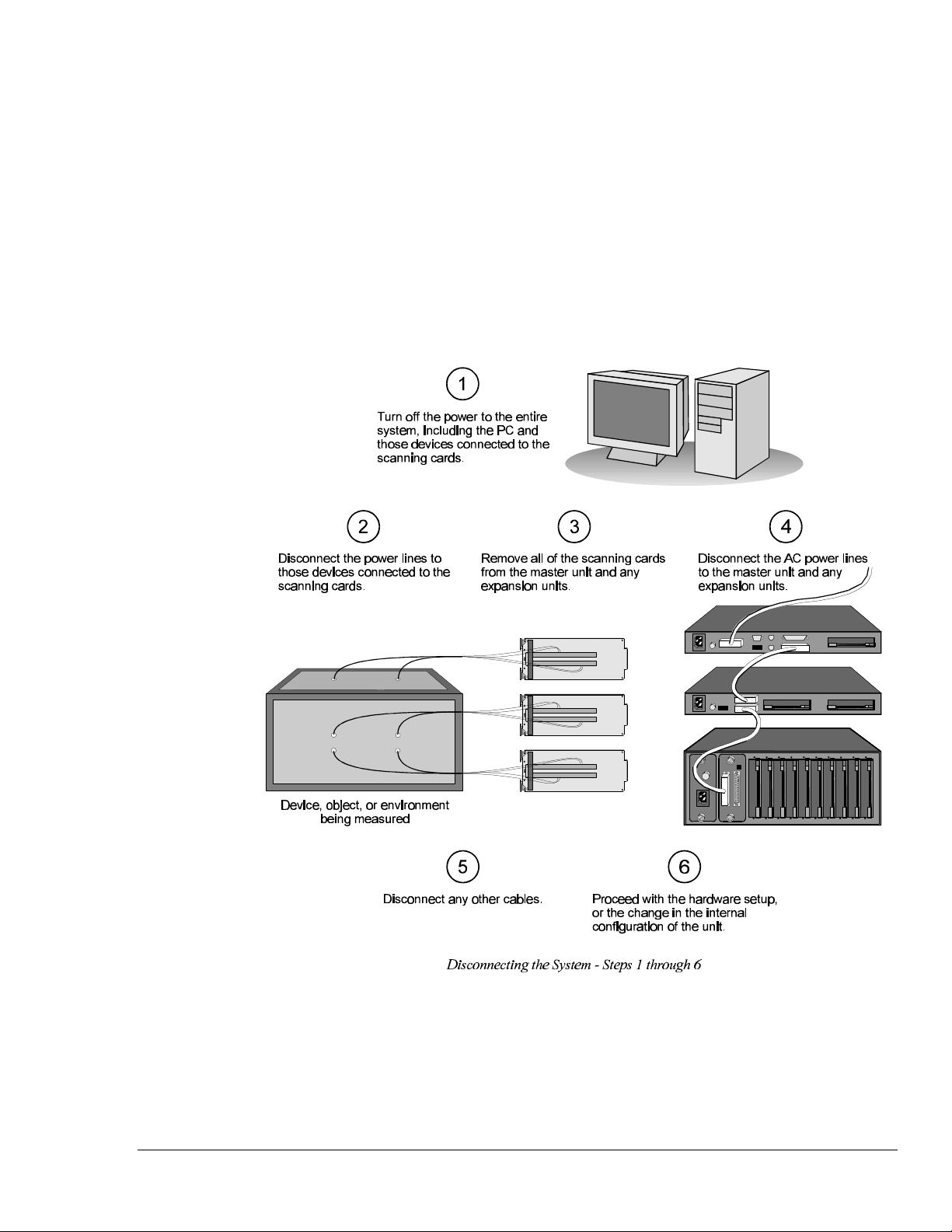
After your system has been connected for the first time, any disconnections of your system should be
made according to the following setup cases:
• Before changing the internal setup – power line selection, fuse, or memory configuration – of
the master or any expansion unit(s): Follow Steps 1 through 5 below, then proceed with Step 6.
• Before changing the external setup – DIP switch settings – of the master or any expansion
unit(s): Follow Step 1 below, then proceed with Step 6.
• Before changing or removing the scanning card(s) or input connection(s) from the system:
Follow Steps 1 through 3 below, then proceed with Step 6.
• Before changing or removing the master unit or any expansion unit(s) from the system: Follow
Steps 1 through 5 below, then proceed with Step 6.
To Disconnect the System During Setup
TempScan / MultiScan User's Manual Chapter 1: System Overview 7
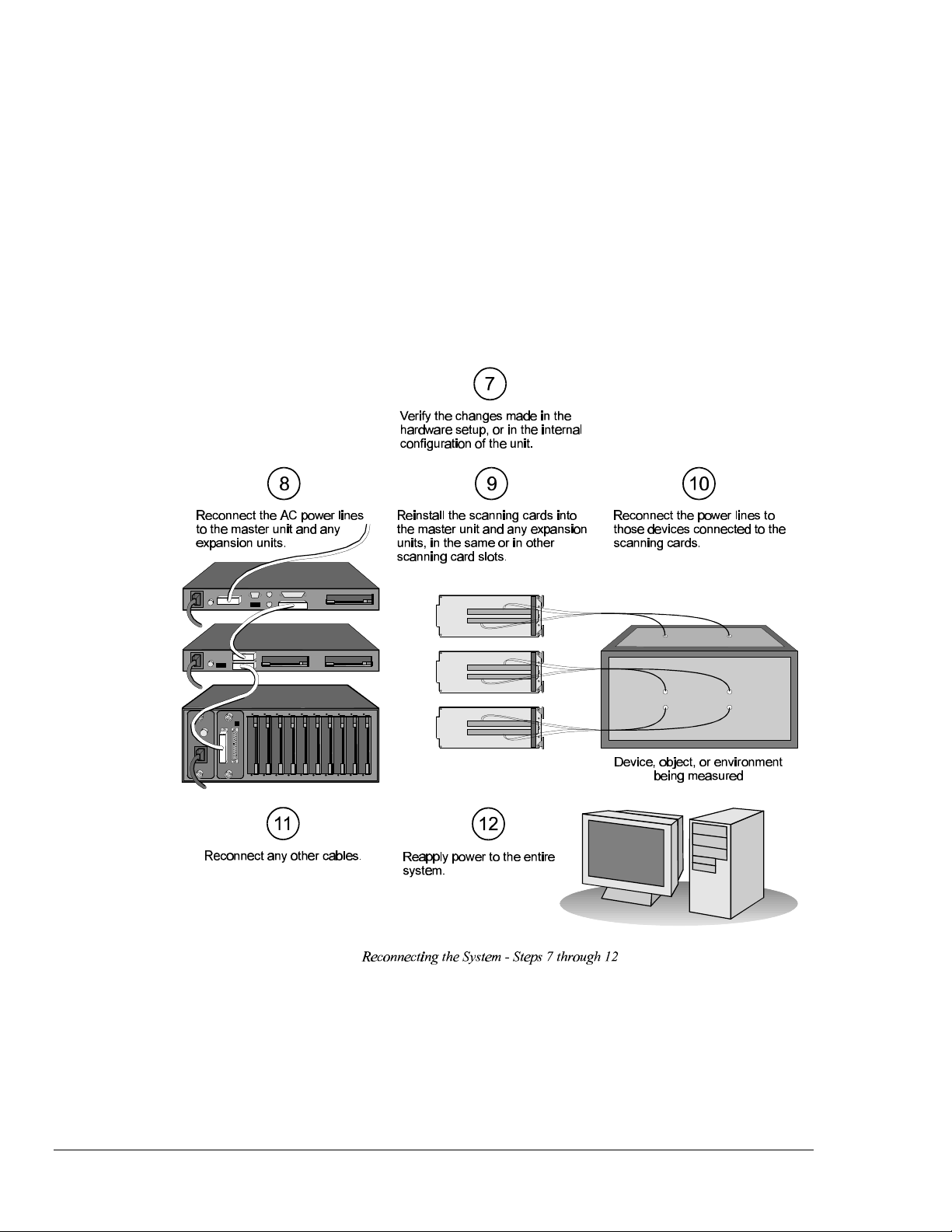
When connecting your system for the first time or subsequent time thereafter, any reconnections of
your system should be made according to the following setup cases:
• After changing the internal setup – power line selection, fuse, or memory configuration – of the
master or any expansion unit(s): Follow Steps 7 through 11 below, then proceed with Step 12.
• After changing the external setup – DIP switch settings – of the master or any expansion
unit(s): Follow Step 7 below, then proceed with Step 12.
• After changing or removing the scanning card(s) or input connection(s) from the system:
Follow Steps 7, 9 and 10 below, then proceed with Step 12.
• After changing or removing the master unit or any expansion unit(s) from the system: Follow
Steps 7 through 11 below, then proceed with Step 12.
To Reconnect the System During Setup
8 Chapter 1: System Overview TempScan / MultiScan User's Manual

Software Products
ChartView
ChartView is a Windows-based setup and acquisition application which provides a graphical stripchartstyle user interface that allows the easy configuration of hardware, acquisition, and display parameters.
Compatible with both Windows 3.X and Windows 95/NT, ChartView features a no-programming
approach that enables data collection and display within minutes of unpacking the TempScan/1100 or
MultiScan/1200. ChartView is designed for users new to this kind of software, and for users with
more-powerful less-resource-limited PC systems.
TempView
TempView is a Windows-based setup and acquisition application which provides a graphical
spreadsheet-style user interface that allows the easy configuration of hardware, acquisition, and display
parameters. Compatible with both Windows 3.X and Windows 95/NT, TempView features a noprogramming approach that enables data collection and display within minutes of unpacking the
TempScan/1100 or MultiScan/1200. TempView is designed for users already familiar with earlier
versions of TempView, and for users with less-powerful resource-limited PC systems.
PostView
In addition to ChartView or TempView data-logging software, each software package includes
PostView, a Windows-based post-acquisition data-review program. PostView can be launched from
within TempView or as a stand-alone Windows application. It provides a stripchart recorder-like
graphical display for scrolling through previously acquired data files. PostView also allows
simultaneous display of up to 16 channels, and provides independent cursors for each channel.
ScanCal
Also included with ChartView or TempView data-logging software is ScanCal, a Windows-based
application that automates instrument calibration. ScanCal provides familiar pull-down and toolbar
menus for easy calibration within the Windows 3.X or Windows 95/NT environment.
TempScan / MultiScan User's Manual Chapter 1: System Overview 9

- Notes
10 Chapter 1: System Overview TempScan / MultiScan User's Manual

TempScan/1100 & MultiScan/1200 2
Introduction……11
The Package……11
Front Panel Indicators……12
Rear Panel Switches & Connectors……13
TempScan/1100 & MultiScan/1200 Specifications……14
Hardware Configuration……17
IEEE 488 Configuration……18
RS-232/RS-422 Configuration……18
Calibration Protection Configuration……23
Digital I/O Configuration……23
TTL Output & Trigger Input Configuration……24
Expanded Memory Configuration……25
Scanning Card & Channel Expansion……26
Introduction
The Package
All TempScan/1100 and MultiScan/1200 components are carefully inspected prior to shipment. When
you receive your temperature-and-voltage measurement system, carefully unpack all items from the
shipping carton and check for any damage which may have occurred during shipment. Promptly report
the damage to the shipping agent and your sales representative. Retain all shipping materials in case
you must return the unit to the factory.
Every TempScan/1100 or MultiScan/1200 package includes the following items listed by part number:
• TempScan/1100 or MultiScan/1200: High-Speed Temperature & Voltage Instruments
• 296-0601: Programmed Disks in IBM format, including the ChartView and TempView Software
• Temp/Multi-901: TempScan / MultiScan User’s Manual
• PR-10: License Agreement
• PR-2: Warranty Card
• 199-0800: Accessories Kit, which includes the following:
• CN-18-50: DB50 Digital I/O Mating Connector
• CA-1: Power Cable
• FE-1: Rubber Feet (4)
• EN-6: Rack Ears (2)
• HA-41-6: Rack Screws (4)
• PR-9: Rack Mounting Instructions
• FU-1-.5: 1/2A Replacement Fuse
• FU-1-.25: 1/4A Replacement Fuse
TempScan / MultiScan User's Manual Chapter 2: TempScan/1100 & MultiScan/1200 11

Front Panel Indicators
Ten (10) LED indicators on the front panel of either the TempScan/1100 or MultiScan/1200 display the
status of the temperature-and-voltage measurement system:
• ALARM: ON when an alarm has occurred. The indicator remains ON until the alarm condition
clears. OFF when no alarm condition exists.
• TRIGGER: Flashes when Armed and waiting for a Trigger; is ON continuously when triggered; is
OFF when data collection is finished. The Trigger is also turned OFF by IEEE DCL or SDC.
• SCAN: ON when the unit is storing a channel scan in its internal buffer.
• SEND: (For RS-232/RS-422 operation only) ON when transmitting data to the serial interface.
• RECEIVE: (For RS-232/RS-422 operation only) ON when receiving data from the controlling
computer.
• TALK: (For IEEE 488 operation only) ON when the unit is in the Talker state, OFF when the unit
is in the Idle or Listener state.
• LISTEN: (For IEEE 488 operation only) ON when the unit is in the Listener state, OFF when the
unit is in the Idle or Talker state.
• SRQ: (For IEEE 488 operation only) ON when the unit has generated a Service Request (SRQ),
OFF when no SRQ is pending. For more information, see command Set SRQ Mask (M).
• ERROR: ON when an error has occurred, OFF when no error condition exists. For more
information, see command Query Error Status (E?).
• POWER: ON when power is applied to the unit and the power switch on the back panel is in the
ON position (depressed). OFF if power is not present.
12 Chapter 2: TempScan/1100 & MultiScan/1200 TempScan / MultiScan User's Manual
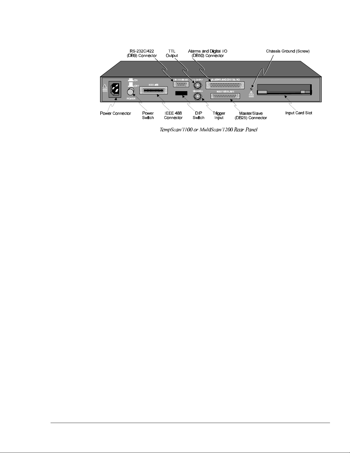
Rear Panel Switches & Connectors
Two (2) switches, seven (7) connectors, one (1) grounding nut, and one (1) input card slot on the rear
panel of either the TempScan/1100 or MultiScan/1200 provide power, IEEE 488 addressing,
triggering, a single point grounding node, and I/O connections.
• Power Switch: Used to turn power to the unit ON and OFF. When the switch is in the depressed
position the power is ON. When in the extended position, the power is OFF.
• DIP Switch: For IEEE 488: Used for selecting IEEE 488 communication and bus address. For
RS-232/RS-422: Used for selecting RS-232/RS-422 serial communication, handshaking, parity and
baud rate. Microswitch 9 is used to enable/disable the hardware protected portion of NV-RAM.
• Power Connector: Provides power for the unit. Internally configurable for either 105-125 or 210-
250 VAC, 50/60Hz, plus fuse circuit breaker.
• IEEE 488 Connector: Port for the IEEE 488 interface.
• RS-232C/RS-422 Connector: DB9 serial port for operation at remote distances from controlling
computer supports 300 to 9,600 baud using RTS/CTS or XON/XOFF handshaking (XON/XOFF
for ASCII transmissions only).
• TTL Output Connector: BNC TTL scan output signal occurs for each channel scan; used for
synchronizing other equipment with TempScan/1100 or MultiScan/1200 acquisition.
• Trigger Input Connector: BNC trigger input for starting and/or stopping acquisition of the TTL
output signal.
• Alarms & Digital I/O Connector: DB50 port offers easy access to Alarms and Digital I/O (32
digital outputs and 8 digital inputs)
• Master/Slave Connector: DB25 master/slave port connects to Exp/10A and/or Exp/11A expansion
slave units to support applications of up to 992 channels with the TempScan/1100 master unit, or
up to 744 channels with the MultiScan/1200 master unit.
• Grounding Screw: An external single-point grounding node has been supplied for (but not limited
to) thermocouple shield termination.
TempScan / MultiScan User's Manual Chapter 2: TempScan/1100 & MultiScan/1200 13

TempScan/1100 & MultiScan/1200 Specifications
CAUTIONCAUTION
Please read this manual carefully! If equipment is used in any manner not
specified in this manual, the protection provided by the equipment may be
impaired.
Note:
Channels
Number of Slots: One (1) slot
Number of Channels (TempScan/1100): Up to 32 differential thermocouple or voltage inputs, or up
Number of Channels (MultiScan/1200): Up to 24 differential thermocouple or voltage inputs;
Channel Attributes: High and low set points; hysteresis values for high and low set points.
Scan Sequence: Any combination of temperature and voltage channels may be scanned, but channels
Scan Interval: Absolute time between scans (hh:mm:ss.s); min = 00:00:00.0, max = 99:59:59.9.
Scanning Modes (TempScan/1100): For thermocouples up to 500 feet: 960 channels/sec @ 60 Hz;
Scanning Modes (MultiScan/1200): For multi-channel scanning: 147 channels/sec @ 50 or 60 Hz;
Triggers
Installation Category: For CE: Category 1.
Programmable Triggering: Temperature or Voltage level (above or below), absolute time of day,
Temperature-Level Trigger: Programmable value for any one channel. For MultiScan/1200: This
TTL Trigger: Programmable for rising or falling edges.
Pre-Trigger Count: Programmable integer (< memory size -1).
Post-Trigger Count: Programmable integer.
Trigger Input Connector: External BNC connector
Trigger Output Connector: External BNC connector
These specifications are subject to change without notice.
to 16 RTD inputs; accepts TempTC/32B, TempV/32B, or TempRTD/16B scanning modules
accepts MTC/24 or MHV/24 scanning modules.
are scanned in ascending numerical order.
Note that specifying a value of 00:00:00.0 results in no delay between channel scans.
800 channels/sec @ 50 Hz; For thermocouples over 500 feet: 240 channels/sec @ 60 Hz, 200
channels/sec @ 50 Hz.
For 32-point line-cycle averaging enabled: 44 channels/sec @ 60 Hz, 38.5 channels/sec @ 50 Hz;
For single-channel burst mode: 1 channel @ 20K samples/sec.
alarm condition (on or off), IEEE GET, IEEE TALK, external TTL trigger (rising or falling),
specified number of readings.
trigger not available when in single-channel burst mode.
14 Chapter 2: TempScan/1100 & MultiScan/1200 TempScan / MultiScan User's Manual

Data Storage & Format
Storage: 128 K reading (256 Kbyte) standard; optional 500 K reading (1 Mbyte), 2 M reading (4
Mbyte), 4 M reading (8 Mbyte).
Data Formats: ASCII and binary; binary format returns a 16-bit compensated and linearized
temperature value (0.1°C/bit); user-programmable for hi/low byte or low/hi byte. Note that high
speed DMA transfers are binary format only.
Statistical Parameters: High, Low, and Last available per channel. For MultiScan/1200: Not
available when in single-channel burst mode.
Time Stamping: Available for each scan group and for each channel’s high, low, and last parameters.
For MultiScan/1200: Not available when in single-channel burst mode.
Time Format: Absolute Time/Date stamping (hh:mm:ss.mil,MM/DD/YY), relative Time/Date
stamping (+hh:mm:ss.mil,DDDDDDD) and scan interval timebase (hh:mm:ss.t). For
MultiScan/1200: Not available when in single-channel burst mode.
Alarm Stamp: Available for each scan group. For MultiScan/1200: Not available when in single-
channel burst mode.
Digital Input Stamp: Available for each scan group. For MultiScan/1200: Not available when in
single-channel burst mode.
IEEE 488 Interface
CAUTIONCAUTION
The IEEE 488 terminal must only be used to control a non-isolated IEEE 488
system. The common mode voltage (cable shell to earth) must be zero.
Interface Use: Digital communication (as opposed to analog) for IEEE 488 compliant computer
platforms, as well as IEEE 488 compliant platform-independent configurations. Messages sent 1
byte (8 bits) at a time. Supports data rates up to 1 Mbyte/sec. Up to 15 devices can be connected
to one bus. Total bus length up to 20 meters. Allowable cable distance between devices is up to 2
meters. Message transactions are hardware handshaked.
Installation Category: For CE: Category 1.
Implementation: SH1, AH1, T6, TE4, L4, LE4, SR1, PP0, RL0, DC1, DT1, C0, E1.
Programmable Parameters: Alarm set points, thermocouple type, temperature units, Trigger level,
Pre-Trigger and Post-Trigger scan interval, Trigger mode, SRQ mask, scan count, Pre-Trigger
count, digital input, digital output, real time settings, data output format, and terminators.
Data Transfer Speed: Up to >300 Kbytes/s.
Connector: Standard IEEE 488 connector with metric studs.
RS-232/RS-422 Serial Interface
CAUTIONCAUTION
The RS-232/RS-422 terminal is only for connecting devices having signals at serial
communications levels.
Installation Category: For CE: Category 1.
Baud Rates: 300, 600, 1200, 2400, 4800 and 9600.
Data Bits: 8.
Stop Bits: 1.
Parity: Even, Odd, None.
Handshaking: RTS/CTS, XON/XOFF (for ASCII transmissions only).
Connector: Male DB-9.
TempScan / MultiScan User's Manual Chapter 2: TempScan/1100 & MultiScan/1200 15

Digital I/O Interface & Alarms
Installation Category: For CE: Category 1.
Number of Digital Inputs: 8 bits, TTL level compatible.
Number of Digital Outputs: 32 bits, TTL level compatible. Can be programmed as alarms. Note that
the 32 TTL outputs can be set or cleared via program control.
Alarm Conditions: May be detected by SRQ or by software query (SPoll or U command).
Alarm Update Rate: Alarms are updated whenever a channel assigned to an alarm is measured.
Connector: Female DB50 50-pin (32 Alarms, 8 digital inputs, 10 ground pins), mating connector
supplied.
General
Installation Category: For CE: Category 2 for Line Voltage Input terminal. All other terminals
are Category 1.
Warm Up: 1 hour to rated accuracy.
Master/Slave Port: Female DB-25.
Chassis Ground Connection: Screw terminal.
Dimensions: 425 mm wide × 305 mm deep × 45 mm high (16.75” × 12” × 1.75”).
Weight: 3.62 kg. (8 lbs.).
Operating Environment: For standard: Indoor use, 0 to 50°C; 0 to 95% RH (non-condensing) to 35°C;
linearly derate 3% RH/°C from 35 to 50°C; For CE: Indoor use at altitudes below 2000 m, 0 to
40°°C; 0 to 80% RH up to 31°°C decreasing linearly 4% RH/°°C to 40°°C.
Control Switches: Power Switch, IEEE 488 or RS-232/RS-422, IEEE address, handshake, parity,
baud rate, calibration memory write enable/disable.
Front Panel Indicators: LED indicators for ALARM, TRIGGER and SCAN; for SEND and
RECEIVE (serial interface); for TALK, LISTEN and SRQ (for IEEE 488 interface); and for
ERROR and POWER.
Power: 105-125 or 210-250 VAC, 50/60 Hz; 20 VA maximum (internal slide switch).
CAUTIONCAUTION
Line Voltage: The protective conductor terminal on the AC line connector must
be connected to an external protective earthing system. Failure to make such a
connection will impair protection from shock.
WARNINGWARNING
Service: This product contains no operator serviceable parts. Service must be
performed by qualified personnel. All terminals, including the AC line and
scanning cards, must be disconnected prior to opening the TempScan/1100 or
MultiScan/1200 case. Internal voltage potentials exist which could cause bodily
injury or death!
Fuse: 1/2A, 250 V, Slo Blo, 3AG (for 105-125V power line) or 1/4A, 250V, Slo Blo, 3AG (for 210-
250V power line).
CAUTIONCAUTION
Fuse Failure: Fuse failure indicates a possible problem within the device circuitry.
If a fuse blows, contact a qualified service representative. Replacement fuses are
to be installed by qualified service personnel with the unit disconnected from the
power source and with all other terminals disconnected. If the line voltage selector
is changed, then the fuse designated for that line voltage must be used.
16 Chapter 2: TempScan/1100 & MultiScan/1200 TempScan / MultiScan User's Manual

Calibration
Calibration of cold junction sensor: Software control of calibrated thermocouple using the ScanCal
program. (Calibration performed for each card and chassis in the system).
Voltage Calibration: Software control of gain and offset.
Calibration Constants: Chassis constants stored in NV-RAM. Card constants stored in card’s on-
board EEPROM.
Hardware Configuration
The TempScan/1100 or MultiScan/1200 unit is equipped with a high-speed IEEE 488 interface and an
RS-232/RS-422 interface. Its IEEE 488 interface is useful in laboratory applications and enables realtime transfers of acquired data to the host computer’s hard drive for inexpensive mass storage. Its RS232/RS-422 interface is ideal in applications that require the placement of instrumentation at remote
distances from the controlling computer, such as process and environmental control.
This unit can be set up with an IEEE 488 or a RS-232/RS-422 interface configuration, as determined
by the DIP switch accessible from the rear panel. This DIP switch via its nine microswitches select
which command set is to be used – IEEE 488 or RS-232/RS-422 – and the operating parameters for
each. The table shows the options for its nine microswitches. Additional DIP switch settings are
shown in the following sections.
Micro- Label Setting Description
switch # IEEE 488 RS-232/RS-422
COMM SELECT 0 IEEE 488 (N/A)
1
2,3
4,5
6,7,8
HANDSHAKE (H/S) 00 No Handshake No Handshake
IEEE ADDRESS or 00 Decimal value 0 No Parity
PARITY 01 Decimal value 8 Odd Parity
IEEE ADDRESS or 000 Decimal value 0 300 baud
BAUD RATE 001 Decimal value 1 600 baud
CHASSIS 0 Disabled Disabled
9
CALIBRATION
ENABLE
Rear Panel DIP Switch
1 (N/A) RS-232/RS-422
01 Software Handshake only
(XON/XOFF) (See Note)
10 Hardware Handshake only
(RTS/CTS)
11 Both Hardware and Software
Handshake
10 Decimal value 16 Even Parity
11 Decimal value 24 (N/A)
010 Decimal value 2 1200 baud
011 Decimal value 3 2400 baud
100 Decimal value 4 4800 baud
101 Decimal value 5 9600 baud (See Note)
110 Decimal value 6 (N/A)
111 Decimal value 7 (N/A)
1 Enabled Enabled
Software Handshake only
(XON/XOFF) (See Note)
Hardware Handshake only
(RTS/CTS)
Both Hardware and Software
Handshake
Note:
(1) XON/XOFF handshaking is valid for ASCII transmissions only. (2) At 9600 baud,
hardware (RTS/CTS) handshaking and possibly software (XON/XOFF) handshaking may be
required to maintain serial performance. However, for RS-422 operation with a Macintosh,
RTS/CTS handshaking is not recommended.
TempScan / MultiScan User's Manual Chapter 2: TempScan/1100 & MultiScan/1200 17

The rear panel DIP switch is read only during power-on or reset and should be set before applying
power. To modify any of these defaults, change the microswitch settings using a small screwdriver.
The enclosure does not need to be opened to change these settings.
IEEE 488 Configuration
One way in which the TempScan/1100 or MultiScan/1200 unit can be controlled, is through its
IEEE 488 port connector. Consequently, when configured as an IEEE 488 bus device, the unit must
have an IEEE 488 bus address.
DIP Switch
For IEEE 488 operation, the single microswitch labeled COMM SELECT should be down (0) on the
rear panel DIP switch . This down (0) position is the factory default. The up (1) position is reserved
for RS-232/RS-422 serial communication. When IEEE 488 operation is enabled, the five
microswitches labeled IEEE ADDRESS are used to configure the required IEEE 488 bus address.
The bus address can be set from 0 through 30 and is read only at power-on or reset. The address is
selected by simple binary weighting. The switch labeled 1 is the least significant bit (LSB); 16 is the
most significant bit (MSB). The factory default is bus address 7. Note that if address 31 is selected, it
defaults to address 30 because the IEEE 488 standard has reserved address 31.
The rear panel DIP switch is read only during power-on or reset and should be set before applying
power. To modify any of these defaults, change the microswitch settings using a small screwdriver.
The enclosure does not need to be opened to change these settings.
RS-232/RS-422 Serial Configuration
Alternatively, the TempScan/1100 or MultiScan/1200 unit can be controlled through its serial port
connector. Complete serial port configuration is accomplished by using both internal jumpers and DIP
switch settings. The internal jumpers, located on the main board behind each serial connector, are used
to configure the port with either RS-232 or RS-422 electrical characteristics. The DIP switch, located
on the rear panel, is used to determine handshaking, parity, and baud rate. Furthermore, the selection
of an RS-232 or RS-422 electrical configuration determines the serial port pattern of pin connector
signals, as discussed later.
Internal Jumpers
The jumpers within the unit configure the serial port electrically as either RS-232 or RS-422. To
change the serial port configuration, it is necessary to perform the following steps:
18 Chapter 2: TempScan/1100 & MultiScan/1200 TempScan / MultiScan User's Manual
WARNINGWARNING
Never disassemble the case while it is connected to the AC power line! Internal
voltage potentials exist which could cause bodily injury or death!
WARNINGWARNING
Never disconnect the AC power line from the TempScan/1100 or MultiScan/1200
while its scanning cards are connected to an external device! Common mode
voltage potentials exceeding 60 VDC or 30 Vrms at the terminals, may exist which
could cause bodily injury or death!
Note:
To Change the Serial Configuration
1. Turn off the power, disconnect the scanning cards, the power line cord, then all other cables from
2. Place the unit on a flat surface. Remove the six screws on top of the case. Remove the top cover.
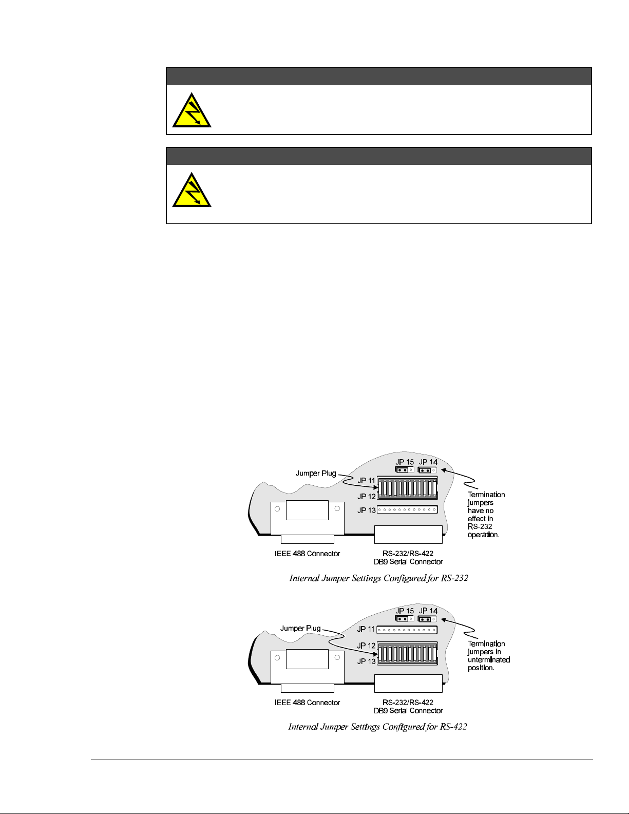
3. The serial port is capable of operating in RS-232 or RS-422 mode. This selection is done via a set
If disassembly or disconnections are necessary, first turn off the power, then disconnect the
scanning cards, next disconnect the AC power line, and then any other cables, prior to unit
disassembly.
the unit. For more information, see section Disconnecting & Reconnecting the System During
Setup on page 6.
of hardware jumpers located on the main board behind the serial connector. A 12-position jumper
plug must be inserted in one of the two available positions for proper operation (across JP11 and
JP12 for RS-232, across JP12 and JP13 for RS-422). These jumpers are factory set for RS-232 as
shown in the figure. To reconfigure the serial port for RS-422 operation, remove the jumper plug
and reinsert it into the lower 2 rows of jumpers.
TempScan / MultiScan User's Manual Chapter 2: TempScan/1100 & MultiScan/1200 19

4. If configured for RS-422, the port’s Receive Data (RxD+) and Clear to Send (CTS+) input lines
may optionally be terminated with a 100-Ohm resistor. Termination resistors are selected by
positioning the two flea clips (labelled JP14 and JP15). These jumpers are factory set to the
unterminated position, as indicated in the previous figures. Note that when using RS-422 in a
single-ended configuration, ports must be unterminated. Termination jumpers have no effect when
the port is configured for RS-232 operation.
5. Once the jumper(s) have been repositioned for your application, make note of the new jumper
settings for later reference.
6. Carefully reassemble the unit.
Note:
For re-assembly, first reconnect the AC power line (with the power OFF), next reconnect the
scanning cards, and then any other cables, prior to reapplying power to the entire system.
DIP Switch
To configure the TempScan/1100 or MultiScan/1200 for RS-232/RS-422 serial operation, the single
microswitch labeled COMM SELECT must be up (1) on the rear panel DIP switch . The down (0)
position is reserved for IEEE 488 communication. When serial operation is enabled, additional DIP
microswitches configure the following required parameters: Handshaking, parity, and baud rate.
Handshaking. When the RS-232 port is used, the type of handshaking must be selected by the two
microswitches labeled H/S. The options available are: No handshaking, XON/XOFF, RTS/CTS or
both XON/XOFF and RTS/CTS handshaking. Note that XON/XOFF handshaking is valid for ASCII
transmissions only, and for RS-422 operation with a Macintosh, RTS/CTS handshaking is not
recommended.
Parity. The parity must be selected using the two microswitches labeled PARITY. The options
provided are: No parity, odd parity or even parity.
Baud rate. The baud rate is selected using the three microswitches labeled SERIAL BAUD RATE. The
available baud rates are 300, 600, 1200, 2400, 4800, and 9600.
Note:
(1) XON/XOFF handshaking is valid for ASCII transmissions only. (2) At 9600 baud,
hardware (RTS/CTS) handshaking and possibly software (XON/XOFF) handshaking may be
required to maintain serial performance. However, for RS-422 operation with a Macintosh,
RTS/CTS handshaking is not recommended.
The rear panel DIP switch is read only during power-on or reset and should be set before applying
power. To modify any of these defaults, change the microswitch settings using a small screwdriver.
The enclosure does not need to be opened to change these settings.
20 Chapter 2: TempScan/1100 & MultiScan/1200 TempScan / MultiScan User's Manual

Serial Connector Pins
The TempScan/1100 or MultiScan/1200 unit is equipped with one DB-9S serial connector on its rear
panel and requires a DB-9P mating connector. This connector is configured as an IBM PC when RS232 levels are selected, and as a Macintosh when RS-422 levels are selected.
A CA-47 cable connects the unit with the computer. The TempScan/1100 or MultiScan/1200 end has
one DB9 connector, and the computer end has two connectors – one for a DB9 and one for a DB25.
Other crossover-type cables can be used if they are wired as shown in the tables. The tables list the
following four connections from the TempScan/1100 or MultiScan/1200 unit:
• To a DB9 connector configured for RS-232
• To a DB25 connector configured for RS-232
• To a DB9 connector configured for RS-422
• To a Mini DIN8 connector configured for RS-422.
TempScan/1100 or MultiScan/1200
To PC Connection (RS-232)
DB9 Male
Pin & Signal
2 RxD3 TxD5 GND
7 RTS+
8 CTS+
TempScan/1100 or MultiScan/1200
To Macintosh Connection (RS-422)
DB9 Male
Pin & Signal
1 GND
2 RTS+
4 TxD+
5 TxD6 CTS+
8 RxD+
9 RxD-
Cable
Wiring
←←--
--→→
←←→→
--→→
←←--
Cable
Wiring
←←→→
--→→
--→→
--→→
←←-←←-←←--
TempScan/1100 or MultiScan/1200
To PC Connection (RS-232)
DB9 Female
Pin & Signal
3 TxD- 2 RxD2 RxD- 3 TxD5 GND 5 GND
8 CTS+ 7 RTS+
7 RTS+ 8 CTS+
DB9 Male
Pin & Signal
3 GND 1 GND
7 CTS+ 2 RTS+
8 RxD+ 4 TxD+
9 RxD- 5 TxD6 RTS+ 6 CTS+
4 TxD+ 8 RxD+
5 TxD- 9 RxD-
DB9 Male
Pin & Signal
TempScan/1100 or MultiScan/1200
To Macintosh Connection (RS-422)
DB9 Male
Pin & Signal
Cable
Wiring
←←--
--→→
←←→→
--→→
←←--
Cable
Wiring
←←→→
--→→
--→→
--→→
←←-←←-←←--
DB25 Female
Pin & Signal
2 TxD3 RxD7 GND
5 CTS+
4 RTS+
Mini DIN8 Male
Pin & Signal
4 GND
2 CTS+
8 RxD+
5 RxD1 RTS+
6 TxD+
3 TxD-
TempScan / MultiScan User's Manual Chapter 2: TempScan/1100 & MultiScan/1200 21

The following text describes the various pin connector signals:
• Transmit Data Negative (TxD-): This output pin transmits serial data to an RS-232 or RS-422
device. The serial data received is sent with the word length, baud rate, stop bits, and parity
configured for the particular port. This signal is low true.
• Transmit Data Positive (TxD+): This output pin transmits serial data to an RS-422 device only.
The pin functions identically to TxD- except that its polarity is inverted. This signal is high true.
• Receive Data Negative (RxD-): This input pin accepts serial data sent by an RS-232 or RS-422
device. The serial data received is expected to match the word length, baud rate, stop bits, and
parity configuration of the particular port. This signal is low true.
• Receive Data Positive (RxD+): This input pin accepts serial data sent by an RS-422 device only.
It functions identically to RxD- except that its polarity is inverted. This signal is high true.
• Request To Send Positive (RTS+): This output pin is used as a hardware handshake line to prevent
an RS-232 or RS-422 device from transmitting serial data to the TempScan/1100 or
MultiScan/1200 unit when it is not able to accept it. When automatic RTS/CTS handshaking is
selected, the unit will assert (high) the RTS+ signal when greater than 4096 memory locations are
available in its internal buffers. If available memory drops below 4096 bytes, the unit unasserts
(low) the RTS+ signal.
• Request To Send Negative (RTS-): This output pin is used as a hardware handshake line with an
RS-422 device only. The pin functions identically to RTS+ except that its polarity is inverted.
This signal is low true.
• Clear To Send Positive (CTS+): This input pin is used as a hardware handshake line to prevent the
TempScan/1100 or MultiScan/1200 unit from transmitting serial data to an RS-232 or RS-422
device when it is not able to accept it. When RTS/CTS handshaking is selected, the unit will not
Transmit Data (TxD+) out while the CTS+ signal is un-asserted (low). When XON/XOFF or no
handshaking is selected, the CTS+ line is ignored.
• Clear To Send Negative (CTS-): This input pin is used as a hardware handshake line with an RS-
422 device only. It functions identically to CTS+ except that its polarity is inverted. This signal is
low true.
• Ground (GND): This signal sets the ground reference point for the other RS-232/RS-422 input
and output signals.
22 Chapter 2: TempScan/1100 & MultiScan/1200 TempScan / MultiScan User's Manual
 Loading...