

Page 1

User’s Manual
OMB-LogBook
Stand-Alone, Intelligent Systems for
16-bit Data Acquisition and Logging
p/n
OMB-461-0901
Rev.
2.0
Page 2

OMEGAnetSM On-Line Service
http://www.omega.com
6HUYLFLQJ1RUWK$PHULFD
Internet e-mail
info@omega.com
USA:
Canada:
One Omega Drive, Box 4047
Stamford, CT 06907-0047
Tel: (203) 359-1660
e-mail: info@omega.com
976 Berger
Laval (Quebec) H7L 5A1
Tel: (514) 856-6928
e-mail: canada@omega.com
FAX: (203) 359-7700
FAX: (514) 856-6886
)RULPPHGLDWHWHFKQLFDORUDSSOLFDWLRQDVVLVWDQFH
USA and Canada:
Mexico and
Latin America:
Sales Service: 1-800-826-6342 / 1-800-TC-OMEGA
Customer Service: 1-800-622-2378 / 1-800-622-BEST
Engineering Service: 1-800-872-9436 / 1-800-USA-WHEN
TELEX: 996404 EASYLINK: 62968934 CABLE: OMEGA
Tel: (95) 800-TC-OMEGA
En Espanol: (95) 203-359-7803
SM
SM
SM
SM
FAX: (95) 203-359-7807
e-mail: espanol@omega.com
6HUYLFLQJ(XURSH
Benelux:
Czech Republic:
France:
Germany/Austria:
United Kingdom:
It is the policy of OMEGA to comply with all worldwide safety and EMC/EMI regulations that
apply. OMEGA is constantly pursuing certification of its products to the European New Approach
Directives. OMEGA will add the CE mark to every appropriate device upon certification.
The information contained in this document is believed to be correct but OMEGA Engineering, Inc. accepts
no liability for any errors it contains, and reserves the right to alter specifications without notice.
WARNING:
These products are not designed for use in, and should not be used for, patient-connected applications.
Postbus 8034, 1180 LA Amstelveen, The Netherlands
Tel: (31) 20 6418405
Toll Free in Benelux: 06 0993344
e-mail: nl@omega.com
ul. Rude armady 1868
733 01 Karvina-Hranice
Tel: 420 (69) 6311899
e-mail:czech@omega.com
9, rue Denis Papin, 78190 Trappes
Tel: (33) 130-621-400
Toll Free in France: 0800-4-06342
e-mail: france@omega.com
Daimlerstrasse 26, D-75392 Deckenpfronn, Germany
Tel: 49 (07056) 3017
Toll Free in Germany: 0130 11 21 66
e-mail: germany@omega.com
25 Swannington Road,
Broughton Astley, Leicestershire,
LE9 6TU, England
Tel: 44 (1455) 285520
FAX: 44 (1455) 283912
Toll Free in England: 0800-488-488
e-mail: uk@omega.com
FAX: (31) 20 6434643
FAX: 420 (69) 6311114
FAX: (33) 130-699-120
FAX: 49 (07056) 8540
P.O. Box 7, Omega Drive,
Irlam, Manchester,
M44 5EX, England
Tel: 44 (161) 777-6611
FAX: 44 (161) 777-6622
Page 3

How To Use This Manual
This manual explains the setup and operation of the LogBook data acquisition system including LBK and
DBK options.
Quick Start, LogBook/300
powered-up, and using LogView software to collect data.
Quick Start, LogBook/360
powered-up, and using LogView software to collect data.
Chapter 1
LogBook/300 and LogBook/360. Includes system block diagrams, information regarding hardware
connections, and system testing. The chapter includes pinouts for P1, P2, and P3. Instructions on
how to stack modules are included.
System Considerations
–
Chapter 2 – System Power
Requirement Worktable and material concerning the power-related DBK30A, DBK32A, DBK33, and
DBK34.
Chapter 3
LogBook acquisition system. A How To…section provides step-by-step instructions for a variety of
acquisition tasks.
LogView
–
Chapter 4 – LBK Options
remote LogBook Terminal, four-channel Digital-to-Analog Output card, GPS support, Modem
Support, and Upload Scheduler.
Chapter 5 – DBK Expansion Options
expand your acquisition system.
Chapter 6
acquisition. Includes terminology, signal management, channel identification, and signal modes.
A troubleshooting section provides solutions to common noise, wiring, and configuration problems.
Signal Management and Troubleshooting Tips
–
– Provides instructions for getting a basic LogBook/300 system connected,
– Provides instructions for getting a basic LogBook/360 system connected,
describes system features and an operational overview for both
describes power supplies and power requirements. Includes a DBK Power
explains this windows-based application that is used to configure and run your
discusses the RS-422/485 Communications Card, memory expansion,
discusses a large number of DBK options that can be used to
explains basic concepts of data
Appendices
A – Calibrating DBK16 and DBK43A
B – Error Codes
C – Accelerometer Tutorial,
D – CE Compliance,
E – Specifications
F – PostView
G – PC-Card Compatibility
acquisition rates, as well as cards that are not compatible.
Using this equipment in ways other than described in this manual can cause
personal injury or equipment damage. Pay special attention to all cautions and
warnings.
Check the
this manual went to press.
for LogView software and LogBook hardware.
describes general requirements for complying with CE standards.
lists physical and performance specifications for LogBooks, LBKs, and DBKs.
explains how to use this program for post-acquisition data viewing.
README.TXT
primarily for the benefit of DBK4 users.
identifies PC-Cards that are 100% compatible with LogBook’s
&$87,21
file for information that may not have been available at the time
LogBook User’s Manual,
9-1-99
i
Page 4

Table of Contents
Setting Up DBK Cards……3-15
Quick Start, LogBook/300
Quick Start, LogBook/360
1 - System Considerations
LogBook Basics……1-1
Introduction ….. 1-1
Front and Rear Panels……1-2
Highlight of Features …… 1-3
LogBook/300 Block Diagram …… 1-4
LogBook/360 Block Diagram …… 1-5
System Software……1-6
4 - LBK Options
Hardware-Related Details……1-7
PC-Card Swapping……1-7
Physical/Environmental Conditions……1-7
Power Supply……1-8
Microprocessor……1-8
Field-Installation Racks and Enclosures…1-8
P1, P2, P3 Port Connectors……1-9
System Design, Setup, & Expansion…1-13
Steps to Review …… 1-13
Expansion Configurations……1-13
LBK Options……1-13
DBK Options……1-14
Mechanical Setup Options……1-16
System Power Considerations……1-17
5 - DBK Expansion Options
Operational Features……1-18
Data Acquisition, An Overview……1-18
LogBook System File……1-19
Communications……1-19
Triggering and Scan Timing……1-20
Scan Rate Limitations……1-20
Use of Outputs to Alarm and Control……1-22
Acquisition……1-22
Data Storage and Retrieval……1-22
2 - System Power
Overview……2-1
System Connections ……2-4
Installation and Configuration …… 2-4
LogView Setup …… 2-5
DBK30A Rechargeable Battery Module … 2-5
DBK32A Auxilliary Power Supply Card … 2-9
DBK33 Triple-Outlet Power Supply Card 2-10
DBK34 Vehicle UPS Module …… 2-11
3 - Using LogView
Understanding LogView……3-1
Modes of LogView Operation……3-2
LogView Features and Capabilities……3-4
Software User-Interface……3-4
File Management......3-7
How To… Procedures……3-10
Flowchart of a Simple Acquisition……3-11
Using an Attached LogBook……3-11
Using a Remote LogBook……3-13
Simple Data Logging……3-13
ii LogBook User’s Manual
Using Multiple Timebases……3-16
Using Digital 2-Point Calibration……3-17
Using Digital Outputs As Alarms……3-19
Using Exception Capturing……3-20
Menu Descriptions……3-21
File Menu……3-21
View Menu……3-25
Device Menu……3-42
Tools Menu……3-45
Indicators Menu……3-48
LBK Options, Location Reference…… 4-1
LBK/COM/422/485 …… 4-2
LBK/MEM1-U, Expanded Memory
(16 MB Upgrade) …… 4-3
LBK1, Remote LogBook Terminal……4-4
LBK2, Four Channel,
Digital-to-Analog Output ……4-8
LogBook/GPS (LogBook/360 Only)…… 4-9
LogBook/Modem…… 4-11
Overview…… 5-2
LogView Setup……5-3
DBK1 16-Connector BNC Adapter
Module……5-4
DBK4 2-Channel Dynamic Signal Input
Card……5-5
DBK7 4-Channel Frequency-To-Voltage
Input Card……5-11
DBK8 Eight-Channel High-Voltage Input
Card……5-20
DBK9 Eight-Channel RTD Card……5-22
DBK10 3-Slot Expansion Chassis……5-25
DBK11A Screw-Terminal Option Card…5-26
DBK12 and DBK13
Analog Input Multiplexer Cards……5-28
DBK15 Universal Current/Voltage Input
Card……5-31
DBK16 2-Channel Strain-Gage Card……5-34
DBK17 Simultaneous Sample and Hold
Card……5-41
DBK18 Low-Pass Filter Card……5-43
DBK19 Thermocouple Card……5-46
DBK20 & DBK21 Digital I/O Cards……5-49
DBK23 Isolated Digital Input Chassis……5-50
DBK24 Isolated Digital Output Chassis…5-53
DBK25 8-Channel Relay Card……5-57
DBK40 BNC Analog Interface……5-58
DBK41 Ten-Slot Expansion Module……5-60
Page 5

DBK42 16-Slot 5B
Signal Conditioning Module……5-63
DBK43A Eight-Channel
Strain-Gage Module……5-69
DBK44 2-Channel 5B
Signal-Conditioning Card……5-79
DBK45 4-Channel SSH
and Low-Pass Filter Card……5-83
DBK50/51 Voltage Input Modules……5-87
DBK52 Thermocouple Input Module……5-90
DBK53/54 Low/High-Gain
Analog Multiplexing Modules……5-93
6 - Signal Management & Troubleshooting
Overview……6-1
Channel Control and Expansion……6-3
Signal Acquisition……6-4
Sequencer……6-4
Scan Rate……6-5
Triggering……6-5
Counter/Timer Functions……6-5
Simultaneous Sample and Hold (SSH) ……6-6
Input Isolation……6-6
Signal Modes……6-7
References for Differential Modes……6-7
Unipolar and Bipolar Measurement……6-9
12-Bit vs 16-Bit Resolution……6-9
Signal Problems……6-10
Troubleshooting……6-12
Troubleshooting Checklist……6-12
Electrostatic Discharge (ESD) ……6-12
Radio Frequency Interference……6-12
Customer Assistance……6-13
Appendices
A – Calibrating DBK16 & DBK43A
B – Error Codes
C – Accelerometer Tutorial
D – CE Compliance
E – Specifications
F – PostView
G – PC-Card Compatibility
LogBook User’s Manual iii
Page 6

iv LogBook User’s Manual
Page 7
Quick Start, LogBook/300
Hardware Connection……1*
Hardware Configuration…… 3
Software Installation…… 3
LogBook/300 Device Configuration……3
*
Page numbers refer to QS-300 pages.
Reference Notes: You may need to refer to additional sections of this manual.
Chapter 1, for system block diagrams, operational overviews, connections, memory
upgrade procedure, or information on the RS-422/485 option.
Chapter 2, in regard to calculating system power and ensuring an adequate power
supply.
Chapter 4, if using LBK options.
Chapter 5, if using DBK options.
Electric shock hazard. Turn off power to all system-connected devices prior to connecting
or disconnecting cables, or setting hardware configurations. Failure to do so could result
in electric shock or death, and equipment damage, even under low-voltage conditions.
When using LogBook in attached mode, the PC-Card [in LogBook] must already have the
logbook.sys.
file
will appear dead.
Otherwise, LogView cannot communicate with LogBook, and LogBook
Test Hardware…… 5
Acquisition Configuration……5
Calibration…… 6
:$51,1*
Hardware Connection
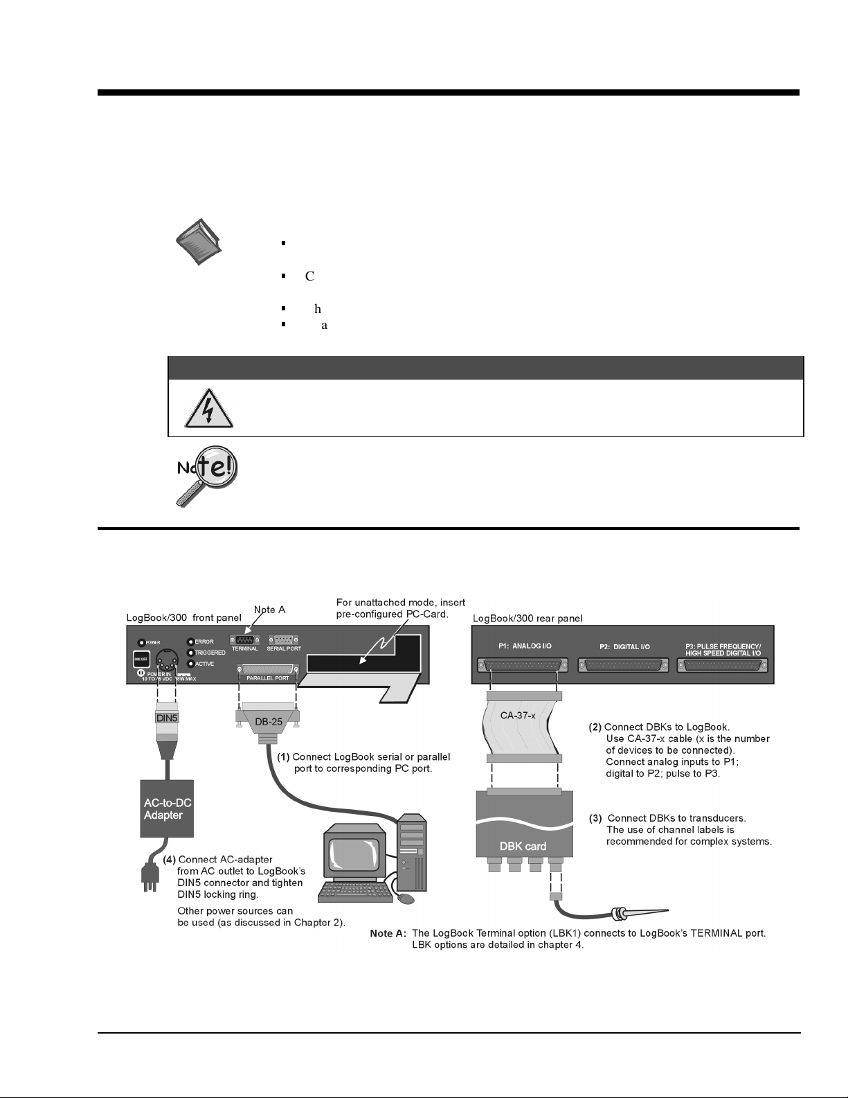
The following hardware-connection figure and procedure are generic; details vary with system complexity.
LogBook/300 System, Basic Connections
Note:
There are two styles of LogBook/300. The earlier version’s PC-Card door is hinged on the right edge. The newer model,
represented in the figure, is hinged on the lower edge.
LogBook User’s Manual,
8-17-99
Quick Start, LogBook/300 QS-300-1
Page 8

After verifying that all equipment power is off, hardware connection typically proceeds as follows.
Refer to the previous figure as needed.
1. Connect LogBook to PC. There are three ways for LogBook to communicate with the host PC.
These are: parallel port, serial port, or by physical transportation of the PC-Card. Note that the
parallel port method is represented in the previous figure.
Parallel port – If using the parallel port, connect the supplied 2-foot parallel port (DB25) cable
a)
to PARALLEL PORT on LogBook, and to the corresponding parallel port on the PC. When this
method is used, the PC must be set to the ECP mode. See ECP Parallel Port, page 4 for
additional information.
Serial port – If using the serial port, connect the supplied 6-foot serial-port (DB9) cable to
b)
SERIAL PORT on LogBook, and to the corresponding serial port on the PC.
c) PC-Card - As described chapter 1’s PC-Card Swapping section, LogBook does not require an
electrical connection to the PC. The PC-Card must be pre-configured [from LogView on the PC]
to contain the desired configuration file. Then the PC-Card is inserted into the corresponding
slot behind the door on the LogBook’s front panel.
2. Connect the LogBook to the DBK cards and modules. Most of the analog DBKs connect to P1 on
the rear panel; the digital DBKs generally connect to P2—refer to documentation for your particular
DBKs in chapter 5 and for general DBK installation details. The CA-37-x cable can daisy-chain
several DBKs including the DBK41, which has a built-in P1 bus connection for 10 DBK cards.
The x in the cable part number refers to the number of devices that can be connected (a CA-37-1
cable actually has two DB-37 connectors). The P1/P2 pinouts are included in chapter 1. Observe the
input signal strength limitation as cautioned below—especially if using a non-DBK source.
For analog signal inputs via P1, do not exceed -35 VDC or +45 VDC.
Exceeding these limits could result in equipment damage.
3. Connect DBK(s) to transducer(s). Follow instructions for particular DBK as described in chapter 5
and for the particular transducer. Some DBKs can accommodate both BNC and screw-terminal
connections.
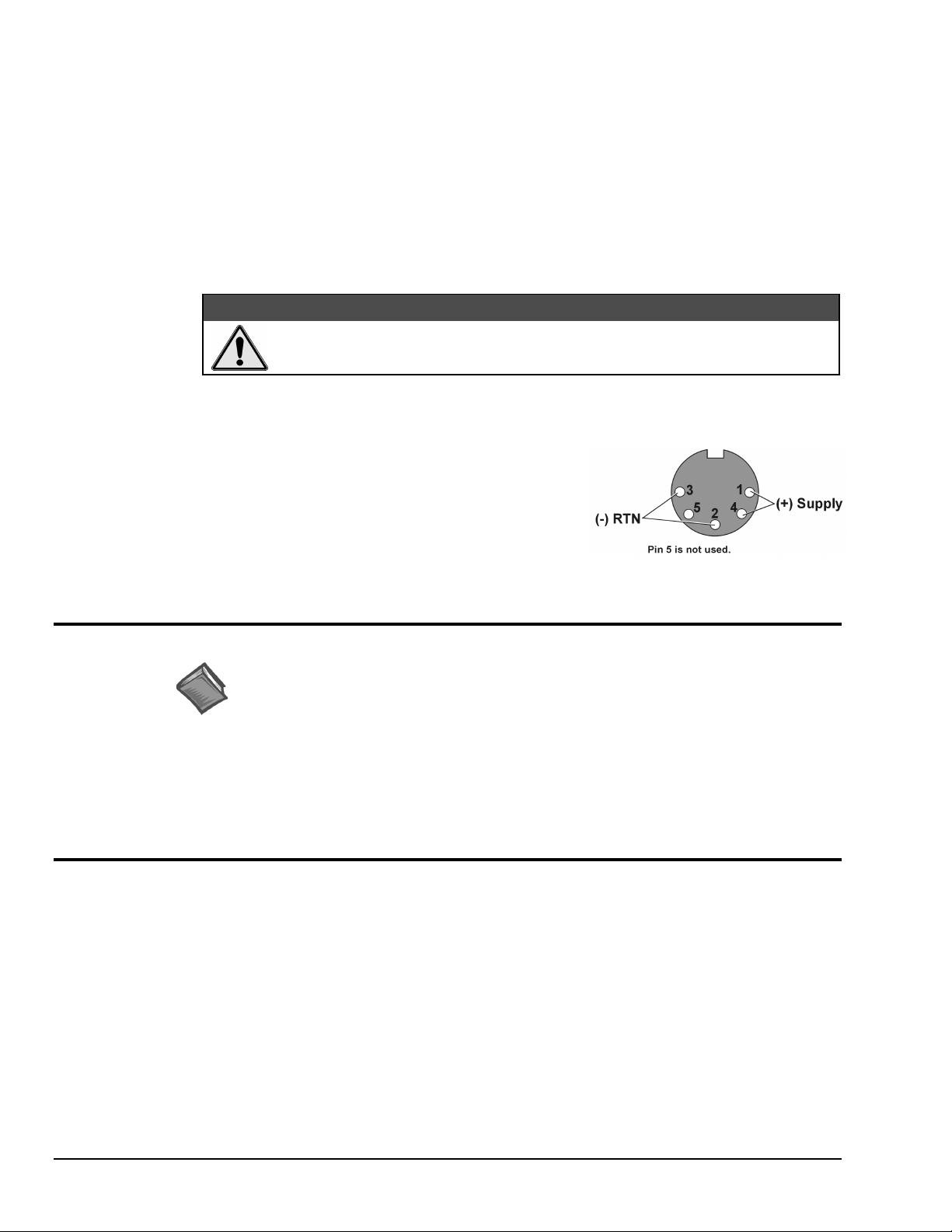
4. Connect LogBook to a suitable power source. The easiest
connection is to use the TR-43 AC-to-DC power source or the
DBK34. DC power sources such as a car batteries, etc must
supply 10 to 45 VDC and use the correct DIN5 pinout (see
figure). A locking DIN5 connector assures a secure power
connection for applications subject to vibration or thermal stress.
5. (optional) Just one cable connects between the LBK1 (via RJ-11 connector) and the LogBook (via a
DB9 connector). The standard cable is 6 ft long, and an optional cable is 25 ft long (see chapter 4 for
LBK1 installation details).
Hardware Configuration
Reference Notes:
(1) Refer to chapter 4 in regard to the various LBK options.
(2) Some DBKs require manual configuration. Refer to chapter 5 for specific DBK
information.
LogBook's top cover does not need to be removed, except to add or remove an LBK option, or to replace
the fuse.
&$87,21
Most LogBook configuration is done via software as described in section, LogBook/300 Device
Configuration. Except when using the RS-485 communication option, LogBook configuration does not
require you to set jumpers or switches.
QS-300-2 Quick Start, LogBook/300,
8-17-99
LogBook User’s Manual
Page 9
Software Installation
Note: The LogBook is supported under Windows95/98 and WindowsNT. Your computer should be a
486 or higher (Pentium
®
recommended) with at least 16 Mbytes of RAM. 32 Mbytes of RAM is
recommended.
Note: Before installing software, ensure LogBook is connected to the selected port
(serial, or ECP-parallel); and power-on the system.
Install installation CD-ROM (or installation disks, as applicable). Run the Setup.exe and follow screen
prompts.
When the software installation is complete, you will be given two options:
•
Exit running the configuration utility—if the LogBook is to be used immediately.
•
Exit and return to operating system—you can run the configuration later from the control panel.
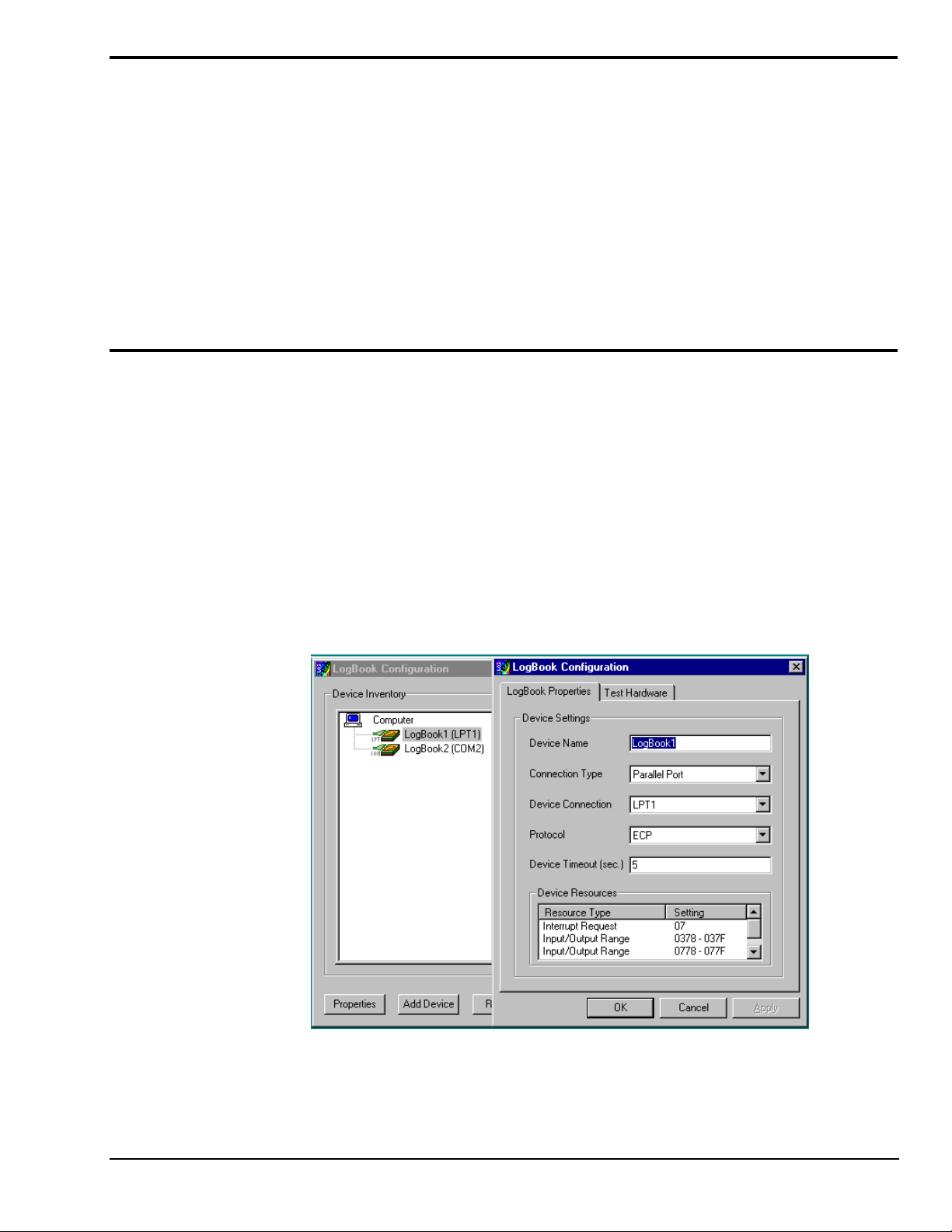
LogBook/300 Device Configuration
A configuration utility is supplied via a control panel applet. The LogBook Configuration applet allows
you to add a device, remove a device, or change existing configuration settings. From this same window,
you can also access a built-in utility to test the connected device for current setup and performance.
LogBook Configuration can be found in the Windows95/98/NT control panel. This can be navigated to
from Window’s desktop Start button:
Start ⇒ Settings ⇒ Control Panel
You can enter LogBook Configuration during driver installation or whenever you wish to add, remove or
change device configuration settings. The following description applies to either method.
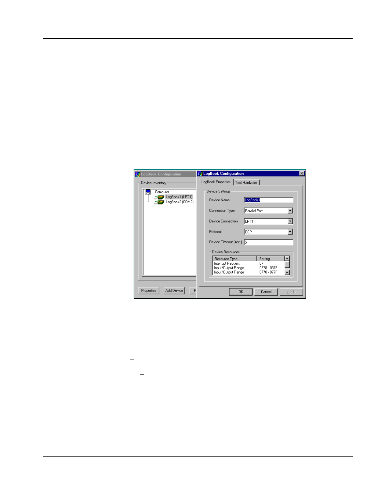
st
The 1
configuration window will display configured devices in the Device Inventory field based on the
port they’re connected to. Devices are indicated by their name and icon. If no devices are currently
configured, no devices will appear in this field. (The figure shows the 1
overlapping.)
st
and 2nd configuration windows
LogBook User’s Manual,
8-17-99
LogBook Configuration Windows
Quick Start, LogBook/300 QS-300-3
Page 10
The 4 buttons across the bottom of the 1st configuration window (previous figure) are used as follows:
•
•
•
•
The 2nd configuration window displays the properties for the selected LogBook. Fields include:
•
•
•
•
•
ECP Parallel Port
Properties. Configuration settings for a device can be changed or modified from the corresponding
properties window. To do so, double-click the device icon or single-click the device and then singleclick the Properties button. The 2
nd
configuration window will appear for the selected device as
shown in the previous figure.
Add. The Add Device button is used to add a device configuration whenever a new device is added
to the system. LogView cannot recognize a device unless listed in the configuration window.
Remove. The Remove button is used to remove a device from the configuration. A device may be
removed if it is no longer installed or if the device’s configuration no longer applies.
Close. The Close button may be used at any time to exit the LogBook Configuration applet.
Device Name is displayed with the default name, numbered successively as configured. This field
can be changed to any descriptive name as desired.
Connection Type can be serial or parallel port.
Device Connection specifies the port name.
Protocol is used to set the parallel port protocol (ECP only) or serial protocol (RS-232 or RS-485).
Device Timeout specifies the number of seconds LogView will be wait for a LogBook response
before displaying an error condition.
To use parallel port communication with an attached LogBook, your PC must support
the ECP protocol AND be set in the ECP mode.
Serial Port
PCs made since 1994 probably support the Enhanced Computer Port protocol (ECP). If your parallel port
does not support ECP, you can communicate with the LogBook via the RS-232 serial port, or you can add
an ECP-compatible ISA board or PC-Card parallel port. Setting the PC to ECP mode varies with different
computers. On some computers, you can enter the BIOS Setup utility from Windows Settings or during
startup by pressing the F1 function key. The Parallel Port Mode property can be found under the Peripheral
Configuration group menu item. If necessary, consult your PC’s documentation or your PC’s manufacturer.
To ensure ECP compatibility after proper setup, use the Test Hardware utility
(described on page 5). Before testing, make sure LogBook is properly connected,
powered on, and that the Parallel Port Mode is set to ECP (in BIOS Setup).
&$87,21
Making errors in BIOS Setup can disrupt your system’s operation. If test hardware
indicates a problem and you have inadequate experience with the BIOS Setup utility,
consult your System Administrator or other qualified individual.
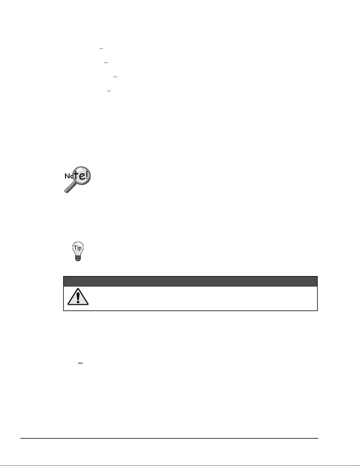
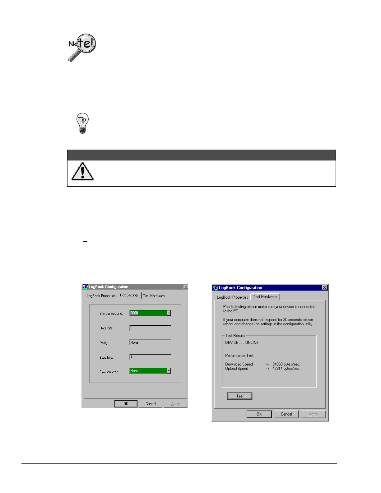
If the selected device is connected to a serial port the properties window will include the fields shown in the
figure at right. Baud rate can be set from 1200 to 115200 bits per second (default 9600). When all fields
have been changed to the desired settings, you can click on one of the following options:
•
Apply to store the device configuration. Parameters are not locked in until you click the Apply
button. If you make changes and don’t click Apply, clicking the Test button in Test Hardware will
yield unexpected errors.
•
OK to store the configuration and exit the current property screen.
•
Cancel to exit the current screen without storing any changes.
•
Test Hardware to test the current device.
QS-300-4 Quick Start, LogBook/300,
8-17-99
LogBook User’s Manual
Page 11
Test Hardware
Before testing LogBook/300:
(a) Verify the device has been properly installed
(b) Make sure the communication cable (serial or parallel) is firmly in place to the proper ports.
(c) Verify the device is powered-on.
To begin the test, click the Test button. Test results should be displayed within a few seconds.
Test results indicate if the device is online (properly connected, powered on and ready to transfer the data)
or offline. If the device is online, Performance Test will display Download and Upload speed rates. These
rates represent the maximum speed at which downloading and uploading files can be performed. Actual
transfer time will depend on channel configuration and the size of the transfer.
LogBook Properties Tab Test Hardware Tab
Testing the LogBook device might cause the system to hang. If test results are not
displayed within 30 seconds, or if the system does not respond properly: reboot the
system. Upon power-up, re-enter the LogBook Configuration and ensure the LogBook
configuration settings are correct. Change the settings as applicable.
Acquisition Configuration
An acquisition is configured using LogView on a PC and then stored as an acquisition setup file on a
PC-Card. The PC-Card may be in an attached LogBook or in the PC to be later manually transferred to an
unattached LogBook. The system’s DBK cards are listed; the scan sequence is defined; the trigger
conditions are specified, etc.
Reference Note: Configuring the acquisition is described in chapter 3, LogView.
LogBook User’s Manual,
8-17-99
Quick Start, LogBook/300 QS-300-5
Page 12

Calibration
Calibration is typically performed automatically through LogView software; however, some DBKs may
require manual calibration. LogView’s 2-point calibration fine-tunes the reading’s slope and offset error
(mx+b). DBKs working with non-linear sensors typically condition/convert the reading to a linear form.
Otherwise, a non-linear analog input signal is difficult to read accurately. Careful use of the calculated
channels may yield usable approximations in simple, limited-range conditions.
Reference Note: An example of 2-point calibration is given in the How To… section of
chapter 3, LogView.
Appendix A details the calibration methods applicable to DBK16 and DBK43.
QS-300-6 Quick Start, LogBook/300,
8-17-99
LogBook User’s Manual
Page 13
Quick Start, LogBook/360
Card Drawer Setup……2
Connect LogBook/360 to PC,
External DBKs, and Power…..5
Hardware Configuration…… 6
Software Installation…… 6
LogBook/360 Device Configuration……7
Test Hardware…… 9
Acquisition Configuration……9
Calibration…… 9
Page numbers refer to QS-360 section.
*
Reference Notes: You may need to refer to additional sections of this manual.
Chapter 1, for system block diagrams, operational overviews, connections, memory upgrade procedure,
or information on the RS-422/485 option.
Chapter 2, in regard to calculating system power and ensuring an adequate power supply.
Chapter 4, if using LBK options.
Chapter 5, if using DBK options.
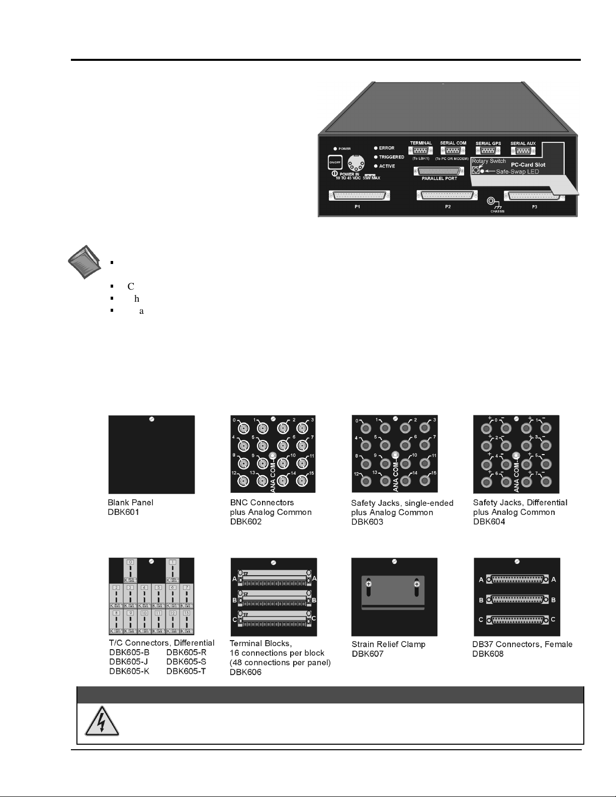
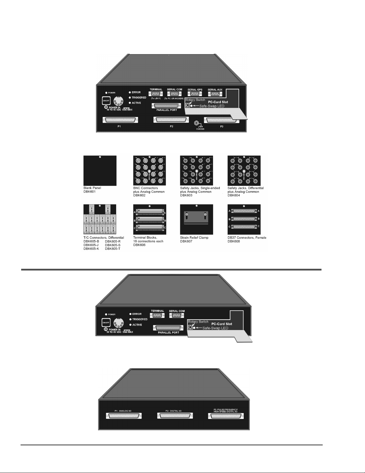
LogBook/360 combines the features and capabilities of LogBook/300 with a DBK60 expansion chassis. The lower
portion of the front panel has three male DB37 connectors (P1, P2, and P3) for system expansion, and a post for
connecting to CHASSIS ground.
The upper section is nearly identical to LogBook/300, and is detailed in chapter 1.
LogBook/360, Front Panel
The rear panel consists of three termination panels. Many different combinations of three panels are possible.
Termination panels available at the time of publication are represented in the following figure.
Electric shock hazard. Turn off power to all system-connected devices prior to connecting or
disconnecting cables, or setting hardware configurations. Failure to do so could result in electric shock
or death, and equipment damage, even under low-voltage conditions.
LogBook User’s Manual,
10-1-99
:$51,1*
Quick Start, LogBook/360 QS-360-1
Page 14
Use ESD tools, containers, and procedures during setup of DBK cards. Electrostatic
discharge can damage some components. To prevent pin damage, align DBK cards with the
backplane DB37 connectors, then gently press them together.
When using LogBook in attached mode, the PC-Card [in LogBook] must already have the file
logbook.sys.
dead.
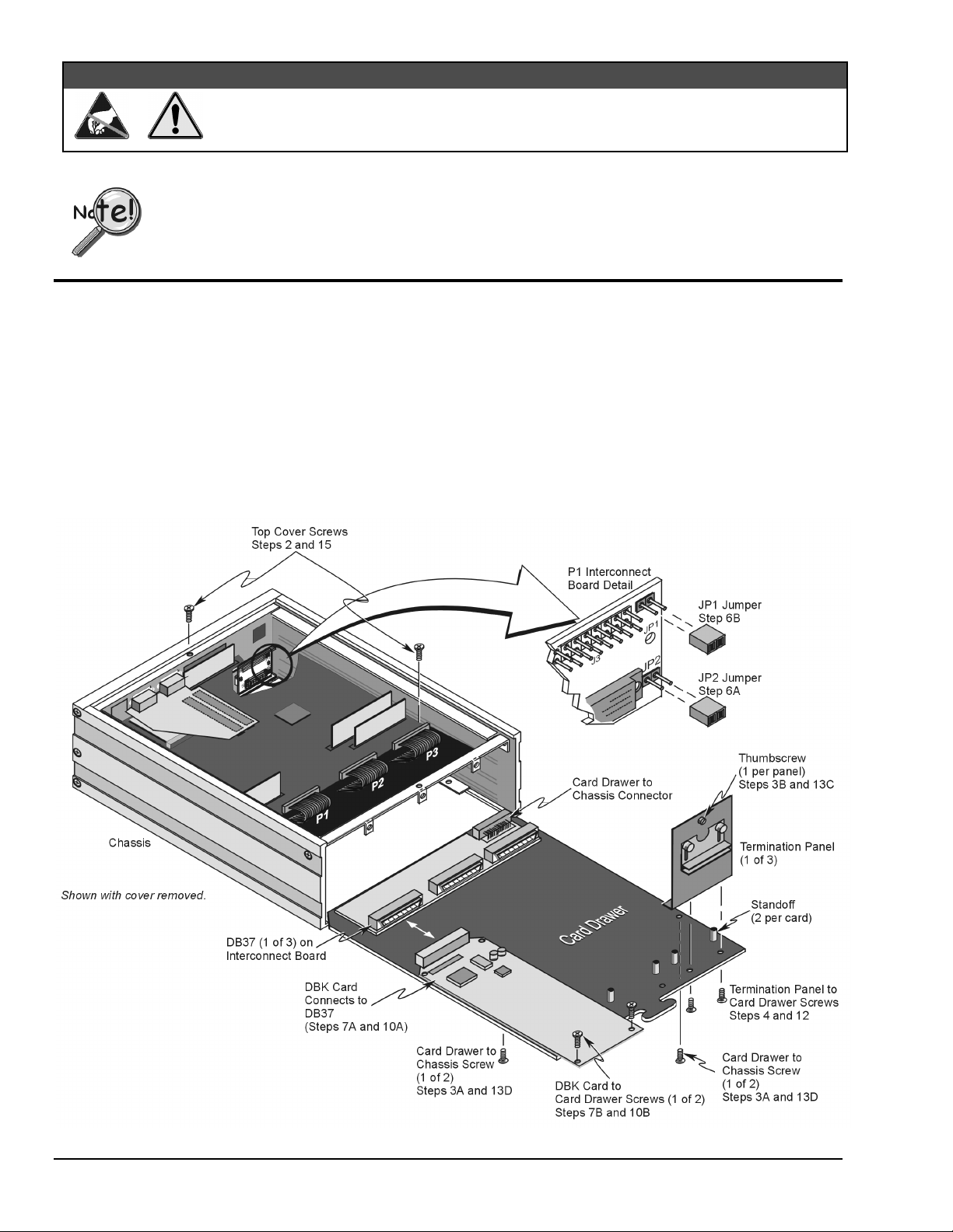
Card Drawer Setup
LogBook/360 can house three DBK cards internally, and makes use of various termination panels as depicted on
page 1 of this Quick Start. For user convenience, a card drawer can be slid free of the device. The following steps
should be used when adding, removing, or changing cards. Refer to the figure as needed.
1 – Turn off system power and disconnect LogBook/360.
Turn power off to the LogBook/360 and all connected devices. Disconnect LogBook/360 from the system.
2 – Remove top cover.
If you need to make any change on the LogBook motherboard, you will need to remove the top cover.
Otherwise, the cover can remain in place. To remove the top cover, simply remove the two top cover screws
and slide the cover free of the device.
&$87,21
Otherwise, LogView cannot communicate with LogBook, and LogBook will appear
QS-360-2 Quick Start, LogBook/360,
10-1-99
LogBook/360, Hardware Setup
LogBook User’s Manual
Page 15

3 – Remove card drawer.
A. Remove the two screws that hold the card drawer to the chassis.
B. Loosen the three termination panel thumbscrews.
C. Carefully pull the card drawer free of the chassis.
4 – Remove termination panels.
For each termination panel, remove the two screws that mount it to the card drawer, then remove the
termination panel.
5 – Determine power requirements.
Depending on the power needs of your system’s DBK cards, you may need to add a power card.
Refer to Chapter 2, System Power, in regard to calculating your power requirement.
If the required power is more than the available power (see chapter 2 for calculations), your system will
require auxiliary power. One of two power supply cards can be used with LogBook:
•
DBK32A – For use with a LogBook, DaqBook, or DaqBoard. It supplies ±15 V.
•
DBK33 – For use with Log Book, DaqBook, DaqBoard, or Daq PC-Card. It supplies +5 V and ±15 V.
6 – Configure chassis for power sources.
Proper jumper configuration limits LogBook’s P1 bus to one power source. The P1 bus should never have more
than one power source.
The JP1 and JP2 jumpers located on the P1 Interconnect Board inside chassis (see previous figure) control the
+5V distribution. Both the JP1 and JP2 jumpers are installed as factory-default.
JP2
A.
.
Only remove the JP2 jumper if cards (on the internal P1 bus) are to be powered from LogBook’s
internal PCB.
JP1
B.
.
Only remove the JP1 jumper if a DBK33 is used with the system.
7 – Install power card if necessary.
If you determined in step 5 that additional power was needed, add a DBK32A or DBK33 power card to the
chassis. Chapter 2 includes information regarding these power-related cards.
A. Carefully align the power card’s DB37 connector with a DB37 connector on the interconnect board and
gently press them together.
B. Mount the power card with two screws into the standoffs on the card drawer.
8 – Configure LogBook/360.
Refer to chapter 1. Note that if a LogBook/360 driver is not available in software, select LogBook/300.
9 – Configure DBK cards.
Configure unique channel addresses with the jumpers on the DBK cards. Some cards have other jumpers and/or
DIP switches. Refer to the particular DBK sections of Chapter 5, as needed.
10 – Install DBK cards.
You must use all analog DBK cards in the LogBook/360; unless you have a factory modification that allows the
use of all digital cards. You can not use both analog and digital cards at the same time.
A. Carefully align the DBK card’s DB37 connector with a DB37 connector on the interconnect board and
gently press them together (see figure).
B. Mount the DBK card with two screws into the standoffs on the card drawer (see figure).
C. Continue installation of any remaining DBK cards.
LogBook User’s Manual,
10-1-99
Quick Start, LogBook/360 QS-360-3
Page 16
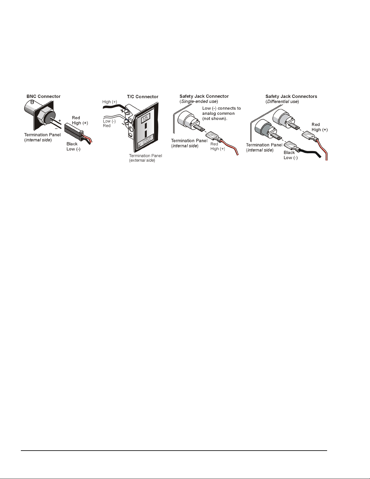
11 – Connect internal signals.
Connect signal inputs from DBK cards to termination panels. DBK cards connect to the termination panels in
various ways (see figure and particular DBK sections in manual):
•
Single-ended connections use analog common.
•
Differential connections require the proper polarity, typically red-to-red for high (+)
and black-to-black for low (-).
•
For thermocouples, red is generally the low side. Always make sure the T/C connector and wire type match
the T/C type used.
12 – Install termination panels.
Mount the termination panels to the card drawer with two screws for each panel.
13 – Install card drawer.
The card drawer slides into the bottom track of the chassis.
A. Hold the card drawer by its handle and tilt it up slightly. Place it on the bottom track of the chassis.
B. Carefully slide the card drawer into the chassis. When it engages the bottom track, level the card drawer and
continue inserting it until it engages with the P1 interconnect board.
C. Tighten the three captive thumbscrews holding the termination panels to the chassis.
D. Install the two screws holding the card drawer to the chassis.
14 – Connect external signals.
Connect signal inputs from sensors to termination panels.
15 – Install top cover.
If the top cover was removed, slide it back into place and secure with two screws.
QS-360-4 Quick Start, LogBook/360,
10-1-99
LogBook User’s Manual
Page 17
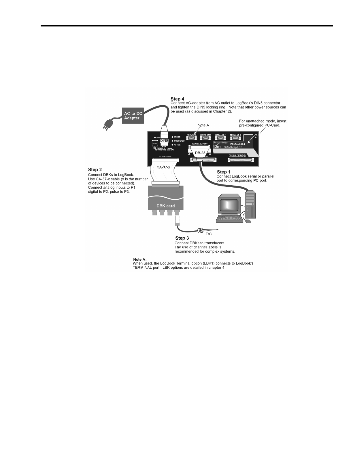
Connect LogBook/360 to PC, External DBKs, and Power*
The following hardware-connection figure and procedure are generic; details vary with system complexity. For
“unattached mode,” a pre-configured PC-Card is inserted in the PC-Card slot, and no connection to a PC is made.
The following figure illustrates the “attached” mode.
*Note: Connecting LogBook/360 to a PC applies to the “attached mode” only. Many applications will make use of
three internal DBK cards only, having no need to attach external DBK cards or modules as discussed in the
following text.
After verifying that all equipment power is off, hardware connection typically proceeds as follows.
Refer to the above figure as needed.
1. Connect LogBook to PC. There are three ways for LogBook to communicate with the host PC.
LogBook User’s Manual,
LogBook/360 System, “Attached Mode,” Basic Connections
Note:
Rear panel connections may be made via terminal blocks, as discussed in the previous section,
Card Drawer Setup
.
These are: parallel port, serial port, or by physical transportation of the PC-Card. Note that the
parallel port method is represented in the previous figure.
a) Parallel port – If using the parallel port, connect the supplied 2-foot parallel port (DB25) cable
to PARALLEL PORT on LogBook, and to the corresponding parallel port on the PC. When this
method is used, the PC must be set to the ECP mode. See
ECP Parallel Port
, page 8 for
additional information.
b) Serial port – If using the serial port, connect the supplied 6-foot serial-port (DB9) cable to
SERIAL PORT on LogBook, and to the corresponding serial port on the PC.
c) PC-Card - As described chapter 1’s
PC-Card Swapping
section, LogBook does not require an
electrical connection to the PC. The PC-Card must be pre-configured [from LogView on the PC]
to contain the desired configuration file. Then the PC-Card is inserted into the corresponding
slot behind the door on the LogBook’s front panel.
10-1-99
Quick Start, LogBook/360 QS-360-5
Page 18
2. Connect LogBook to the DBK cards and modules. For connecting internal DBK cards, refer to the
earlier section entitled, Card Drawer Setup.
Most analog DBKs connect to P1; digital DBKs generally connect to P2. Refer to chapter 5 for your
particular DBKs and for general DBK installation details.
The CA-37-x cable can daisy-chain several DBKs including the DBK41, which has a built-in P1 bus
connection for 10 DBK cards. The x in the cable part number refers to the number of devices that
can be connected (a CA-37-1 actually has two DB-37 connectors).
Note: Chapter 1 includes LogBook P1, P2, and P3 Pinouts.
&$87,21
For analog signal inputs via P1, do not exceed -35 VDC or +45 VDC.
Exceeding these limits could result in equipment damage.
3. Connect DBK(s) to transducer(s). Follow instructions for particular DBK as described in chapter 5
and for the particular transducer. Some DBKs can accommodate both BNC and screw-terminal
connections.
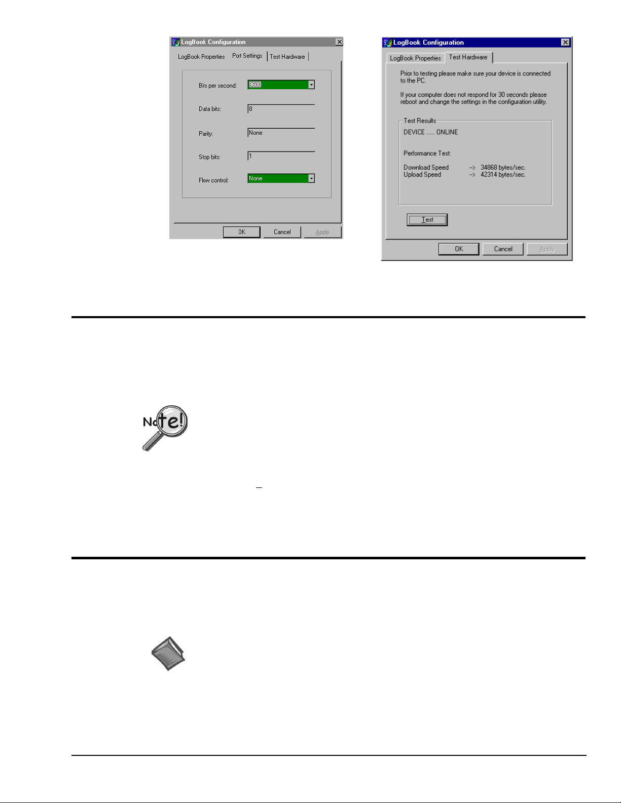
4. Connect LogBook to a suitable power source, such as a
TR-43 AC-to-DC power adaptor or DBK34 vehicle UPS
module. DC power sources such as a car batteries must
supply 10 to 45 VDC and use the correct DIN5 pinout
(see figure). A locking DIN5 connector assures a secure
power connection for applications subject to vibration and
thermal stress.
DIN5 Power Input Connector
As seen on LogBook Front Panel)
(
Hardware Configuration
Reference Notes:
(1) Refer to chapter 4 in regard to the various LBK options.
(2) Some DBKs require manual configuration. Refer to chapter 5 for specific DBK
information.
LogBook's top cover does not need to be removed, except to add or remove an LBK option, or to replace
the fuse.
Most LogBook configuration is done via software as described in section, LogBook/360 Device
Configuration. Except when using the RS-485 communication option, LogBook configuration does not
require you to set jumpers or switches.
Software Installation
Note: The LogBook is supported under Windows95/98 and WindowsNT. Your computer should be a
486 or higher (Pentium
recommended.
Note: Before installing software, you should attach LogBook to the selected port (serial, or
ECP-parallel); and power-on the system.
Install installation CD-ROM (or installation disks, as applicable). Run the Setup.exe and follow screen
prompts.
When the software installation is complete, you will be given two options:
•
Exit running the configuration utility—if the LogBook is to be used immediately.
•
Exit and return to operating system—you can run the configuration later from the control panel.
®
recommended) with at least 16 Mbytes of RAM. 32 Mbytes of RAM is
QS-360-6 Quick Start, LogBook/360,
10-1-99
LogBook User’s Manual
Page 19
LogBook/360 Device Configuration
A configuration utility is supplied via a control panel applet. The LogBook Configuration applet allows
you to add a device, remove a device, or change existing configuration settings. From this same window,
you can also access a built-in utility to test the connected device for current setup and performance.
LogBook Configuration can be found in the Windows95/98/NT control panel. This can be navigated to
from Window’s desktop Start button:
Start ⇒ Settings ⇒ Control Panel
You can enter LogBook Configuration during driver installation or whenever you wish to add, remove or
change device configuration settings. The following description applies to either method.
st
The 1
configuration window will display configured devices in the Device Inventory field based on the
port they’re connected to. Devices are indicated by their name and icon. If no devices are currently
configured, no devices will appear in this field. (The figure shows the 1
overlapping.)
st
and 2nd configuration windows
The 4 buttons across the bottom of the 1st configuration window (previous figure) are used as follows:
•
•
•
•
The 2nd configuration window displays the properties for the selected LogBook. Fields include:
•
•
•
•
•
LogBook User’s Manual,
LogBook Configuration Windows
Properties. Configuration settings for a device can be changed or modified from the corresponding
properties window. To do so, double-click the device icon or single-click the device and then singleclick the Properties button. The 2
nd
configuration window will appear for the selected device as
shown in the previous figure.
Add. The Add Device button is used to add a device configuration whenever a new device is added
to the system. LogView cannot recognize a device unless listed in the configuration window.
Remove. The Remove button is used to remove a device from the configuration. A device may be
removed if it is no longer installed or if the device’s configuration no longer applies.
Close. The Close button may be used at any time to exit the LogBook Configuration applet.
Device Name is displayed with the default name, numbered successively as configured. This field
can be changed to any descriptive name as desired.
Connection Type can be serial or parallel port.
Device Connection specifies the port name.
Protocol is used to set the parallel port protocol (ECP only) or serial protocol (RS-232 or RS-485).
Device Timeout specifies the number of seconds LogView will be wait for a LogBook response
before displaying an error condition.
10-1-99
Quick Start, LogBook/360 QS-360-7
Page 20
ECP Parallel Port
PCs made since 1994 probably support the Enhanced Computer Port protocol (ECP). If your parallel port
does not support ECP, you can communicate with the LogBook via the RS-232 serial port, or you can add
an ECP-compatible ISA board or PC-Card parallel port. Setting the PC to ECP mode varies with different
computers. On some computers, you can enter the BIOS Setup utility from Windows Settings or during
startup by pressing the F1 function key. The Parallel Port Mode property can be found under the Peripheral
Configuration group menu item. If necessary, consult your PC’s documentation or your PC’s manufacturer.
Serial Port
If the selected device is connected to a serial port the properties window will include the fields shown in the
figure at right. Baud rate can be set from 1200 to 115200 bits per second (default 9600). When all fields
have been changed to the desired settings, you can click on one of the following options:
•
•
•
•
To use parallel port communication with an attached LogBook, your PC must support
the ECP protocol AND be set in the ECP mode.
To ensure ECP compatibility after proper setup, use the Test Hardware utility
(described on page 9). Before testing, make sure LogBook is properly connected,
powered on, and that the Parallel Port Mode is set to ECP (in BIOS Setup).
&$87,21
Making errors in BIOS Setup can disrupt your system’s operation. If test hardware
indicates a problem and you have inadequate experience with the BIOS Setup utility,
consult your System Administrator or other qualified individual.
Apply to store the device configuration. Parameters are not locked in until you click the Apply
button. If you make changes and don’t click Apply, clicking the Test button in Test Hardware will
yield unexpected errors.
OK to store the configuration and exit the current property screen.
Cancel to exit the current screen without storing any changes.
Test Hardware to test the current device.
LogBook Properties Tab Test Hardware Tab
QS-360-8 Quick Start, LogBook/360,
10-1-99
LogBook User’s Manual
Page 21

Test Hardware
Before testing LogBook/360:
(a) Verify the device has been properly installed
(b) Make sure the communication cable (serial or parallel) is firmly in place to the proper ports.
(c) Verify the device is powered-on.
Testing the LogBook device might cause the system to hang. If test results are not
displayed within 30 seconds, or if the system does not respond properly: reboot the
system. Upon power-up, re-enter the LogBook Configuration and ensure the LogBook
configuration settings are correct. Change the settings as applicable.
To begin the test, click the Test button. Test results should be displayed within a few seconds.
Test results indicate if the device is online (properly connected, powered on and ready to transfer the data)
or offline. If the device is online, Performance Test will display Download and Upload speed rates. These
rates represent the maximum speed at which downloading and uploading files can be performed. Actual
transfer time will depend on channel configuration and the size of the transfer.
Acquisition Configuration
An acquisition is configured using LogView on a PC and then stored as an acquisition setup file on a
PC-Card. The PC-Card may be in an attached LogBook or in the PC to be later manually transferred to an
unattached LogBook. The system’s DBK cards are listed; the scan sequence is defined; the trigger
conditions are specified, etc.
Calibration
Reference Note: Configuring the acquisition is described in chapter 3, LogView.
Calibration is typically performed automatically through LogView software; however, some DBKs may
require manual calibration. LogView’s 2-point calibration fine-tunes the reading’s slope and offset error
(mx+b). DBKs working with non-linear sensors typically condition/convert the reading to a linear form.
Otherwise, a non-linear analog input signal is difficult to read accurately. Careful use of the calculated
channels may yield usable approximations in simple, limited-range conditions.
Reference Note: An example of 2-point calibration is given in the How To… section of
chapter 3, LogView.
Appendix A details the calibration methods applicable to DBK16 and DBK43.
LogBook User’s Manual,
10-1-99
Quick Start, LogBook/360 QS-360-9
Page 22

QS-360-10 Quick Start, LogBook/360,
10-1-99
LogBook User’s Manual
Page 23
System Considerations 1
LogBook Basics……1-1
Introduction ….. 1-1
Front and Rear Panels……1-2
Highlight of Features …… 1-3
LogBook/300 Block Diagram …… 1-4
LogBook/360 Block Diagram …… 1-5
System Software……1-6
Hardware-Related Details……1-7
PC-Card Swapping……1-7
Physical/Environmental Conditions……1-7
Power Supply……1-8
Microprocessor……1-8
Field-Installation Racks and Enclosures……1-8
P1, P2, P3 Port Connectors……1-9
Reference Notes: Additional system considerations are covered in the following chapters.
Chapter 2, refers to calculating system power and ensuring an adequate power supply.
Chapter 4, details LBK options.
Chapter 5, details DBK expansion options applicable to LogBook.
LogBook Basics
System Design, Setup, and Expansion……1-13
Steps to Review …… 1-13
Expansion Configurations……1-13
LBK Options……1-13
DBK Options……1-14
Mechanical Setup Options……1-16
System Power Considerations……1-17
Operational Features……1-18
Data Acquisition, An Overview……1-18
LogBook System File……1-19
Communications……1-19
Triggering and Scan Timing……1-20
Scan Rate Limitations……1-20
Use of Outputs to Alarm and Control……1-22
Acquisition……1-22
Data Storage and Retrieval……1-22
Introduction
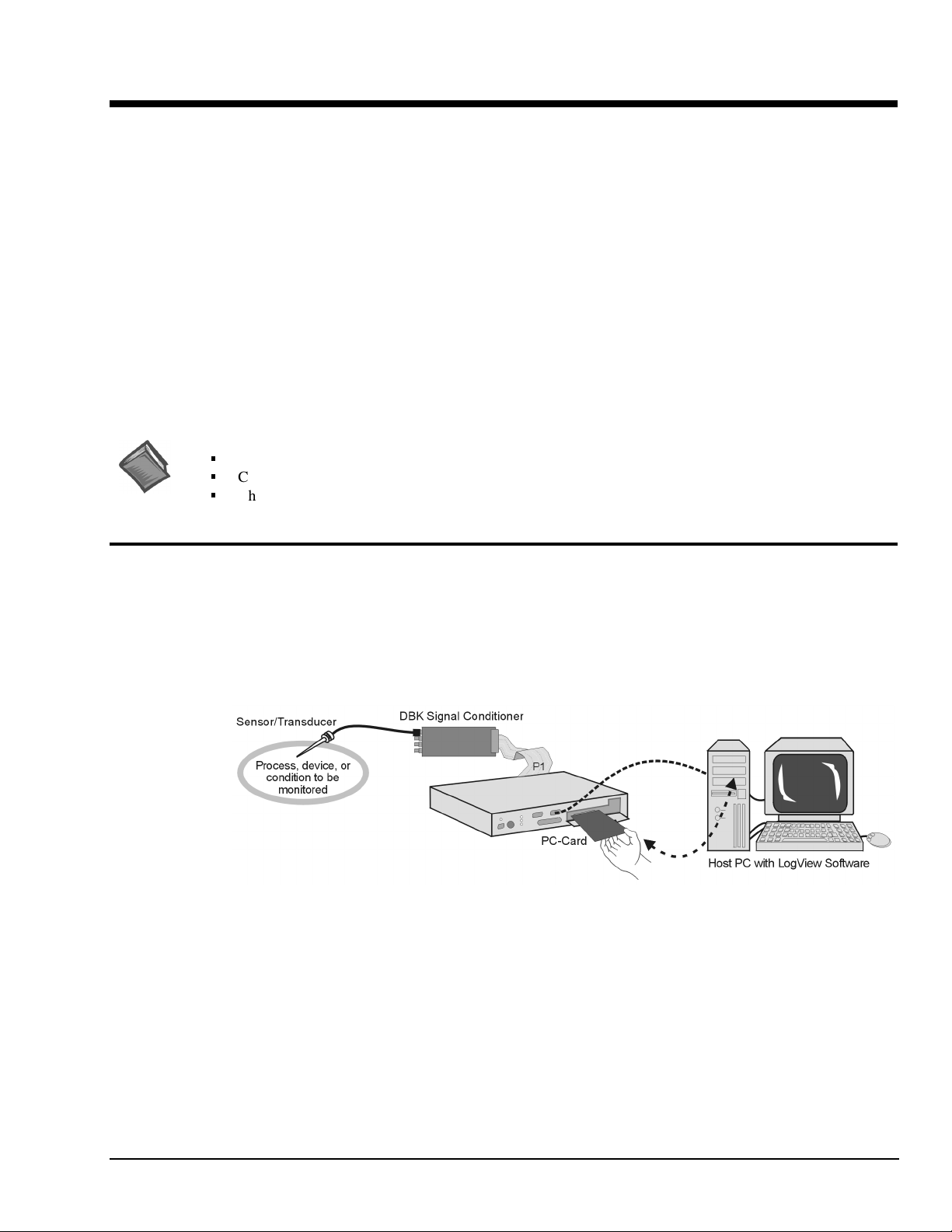
LogBook/300 and LogBook/360 are PC-based data acquisition systems that can work in a stand-alone
mode (no PC present), or linked to a PC. They combine onboard intelligence with a removable PC-Card
that stores the configuration file and the collected data. LogBooks have many options, most of which are
detailed in the LBK and DBK chapters. The PC link can be by serial or parallel port.
LogBook/300, Simple System Setup
The PC-Card holds the configuration file [created by LogView]. The file tells LogBook how to perform a
particular acquisition. The PC-Card also holds the acquired data files. The PC can upload to or download
from the PC-Card by cable if the PC is attached to LogBook, or by physical transport of the PC-Card from
one unit to the other. Multiple configuration files and multiple PC-Cards allow the system to handle
complex data acquisition environments with a large number of data-files.
LogBook User’s Manual,
8-30-99
System Considerations 1-1
Page 24
Front and Rear Panels
Note: Descriptions of panel items appear on the following page.
LogBook/360, Front Panel
LogBook/360, Terminal Panels (A combination of 3 make up the rear panel)
LogBook/300, Front Panel
Note
: In earlier models, the PC-Card Door has a right-edge hinge (not shown).
LogBook/300, Rear Panel
1-2 System Considerations LogBook User’s Manual,
8-30-99
Page 25

LogBook/360 panel items are listed in the following table. Not that LogBook/300 panel items are the same as those on the
360, except as called out in the following bulleted list:
Slight differences in the overlay.
•
P1, P2, and P3 appear on LogBook/300’s rear panel.
•
LogBook/300 has no SERIAL GPS connection.
•
Switches
ON/OFF Depressing the push-button switch turns the power on.
(interior rotary switch) PC-Card door provides access to a rotary switch to set device address when used in an RS-485 network.
Connectors
POWER IN This locking DIN5 input connector accepts +10 to +45 VDC.
PARALLEL PORT This DB-25 plug is a parallel port connector to a host PC (set to ECP mode)
TERMINAL PORT (TO LBK1) This DB-9 socket is a serial port connector for the LBK1 remote control panel (user-interface terminal).
SERIAL COMM
(TO PC OR MODEM)
SERIAL GPS
(LogBook/360 Only)
SERIAL AUX
(LogBook/360 Only)
P1 - ANALOG I/O Provides 16 analog input channels, 3 TTL inputs, and various signals for driving expansion cards.
P2 - DIGITAL I/O Provides 3 8-bit TTL programmable I/O ports and external interrupt input.
P3 - PULSE FREQUENCY /
HIGH-SPEED DIGITAL I/O
(PC-Card door, no label) Door provides access to PCMCIA connector—for removable PC-Card memory devices.
Indicator LEDs
POWER LED lights when power is applied to LogBook and the power switch is depressed into the ON position.
ERROR LED lights steady ON when a routine error occurs (e.g. disk full).
TRIGGERED LED lights after trigger event and during an A/D scan sequence.
ACTIVE LED lights to show that LogBook is ready to begin a scan at the next trigger event.
Safe-Swap Light
(interior green LED)
This DB-9 male serial COM port connects to a host PC or modem.
LogBook/360 only. This DB-9 male serial port option connects to a Global Positioning System.
LogBook/360 only. This DB-9 male serial port option connects to optional auxiliary devices.
Provides 4 16-bit counters, 4 analog outputs, and 16 high-speed digital I/O.
LED flashes for fatal errors; refer to
cleared.
LED lights when it is safe to swap PC-Cards.
LogBook/300 has no SERIAL AUX connection.
•
LogBook/300 has no CHASSIS grounding
•
LogBook/300 does not make use of Terminal Panels.
•
Hardware Errors
Appendix B
in
. No data can be acquired until error is
post.
Highlight of Features
LogBooks can be left unattended for long testing periods and used in environments not suitable for PCs.
With the use of PC-Cards, one PC can support several LogBooks. Other LogBook features include:
•
Onboard processor capable of real-time data reduction and system control in stand-alone mode
•
Non-volatile storage of configuration files and samples via removable, transportable PC-Cards
•
4 MB RAM onboard, expandable to 16 MB
•
100 kHz 16-bit Analog-to-Digital Conversion
•
8 differential, 16 single-ended inputs; expandable to 256 input channels via DBK cards
•
7 gain/input ranges, unipolar and bipolar
•
40 digital I/O lines, expandable to 208
•
4 pulse-counting inputs
•
Gain and unipolar/bipolar settings are programmed in real time (10 µs max)
•
Scan-sequence memory (1024 analog channels plus 128 digital channels)
for any combination of channels/gains
•
Input power: 10 to 45 VDC (AC adapter included)
•
Several LBK options (listed on page 1-13, and detailed in chapter 4)
•
Several DBK options (listed on page 1-14 detailed in chapters 2 and 5)
LogBook User’s Manual,
8-30-99
System Considerations 1-3
Page 26
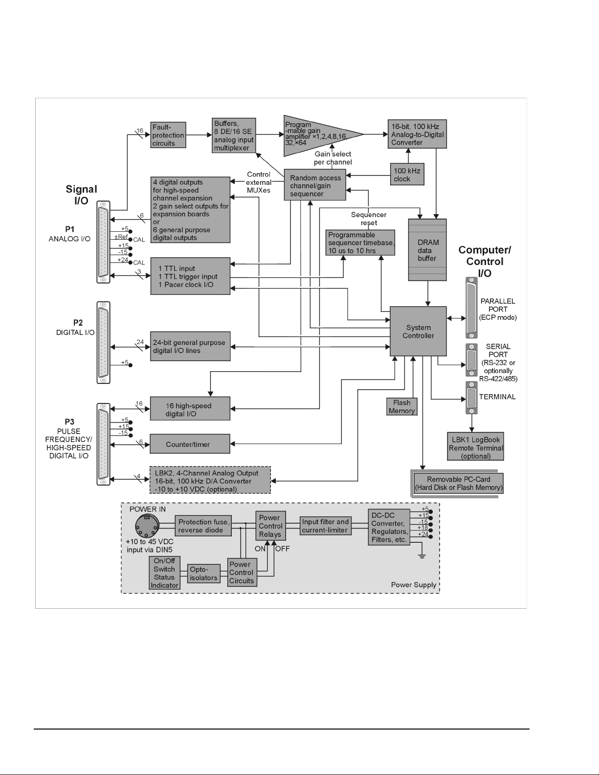
LogBook/300 Block Diagram
1-4 System Considerations LogBook User’s Manual,
8-30-99
Page 27
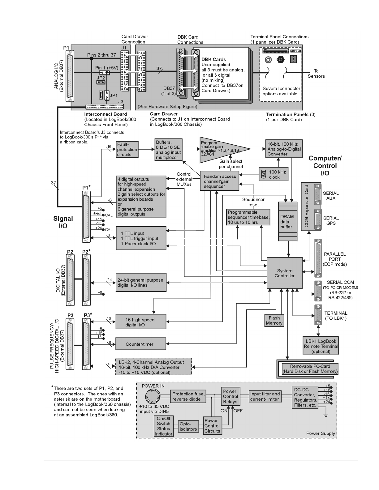
LogBook/360 Block Diagram
LogBook User’s Manual,
8-30-99
System Considerations 1-5
Page 28

The following components are represented in the previous block diagrams. Certain items apply only to
LogBook/360, as noted.
•
Removable PC-Card. A 12-520 MB capacity holds the software, operating system, user
configurations and the acquired data. The PC-Card is at the center of LogBook operations.
A PC-Card [pre-programmed by LogView] ensures an unattached LogBook comes up properly.
•
Power Supply. The internal power supply accepts an input of 10 to 45 VDC and supplies filtered
regulated voltages to its internal circuits and to accessories connected via P1/2/3. An external AC
adapter for all standard voltages is included with the system.
•
System Controller. A microprocessor chip is used within LogBook with either 4 MB (standard) of
RAM or 16 MB (optional). A field-upgradeable 512 KB Flash memory is used to store the system
startup code, self-diagnostics, and FPGA configuration.
•
Analog Input via P1. 16 main channels that can each accommodate 16 sub-channels via
multiplexing for a total of 256 analog input channels. Fault protection and buffer circuits prevent
overloads and cross-channel noise due to impedance mismatch.
•
A/D Converter. The A/D converter uses 16-bit resolution @ 100 kHz sample rate.
•
Digital I/O. 16 high-speed digital inputs via P3, three 8-bit TTL programmable I/O ports via P2,
three TTL inputs via P1. Note that LogBook/360 has P1, P2, and P3 connectors on the motherboard
that are connected [by ribbon cable] to secondary P1, P2, and P3 connectors [located on the chassis
front panel]. LogBook/300’s P1, P2, and P3 are located on the rear panel.
•
LBK2 Analog Output (optional): This option provides four channels of analog output,
16-bit @ 100 kHz @ ±10 VDC.
•
LogBook/360 only, Interconnect Board, Card Drawer (for three DBK cards), and
three Terminal Panels.
•
Computer/Control/I/O – Includes: PARALLEL PORT (ECP Mode), SERIAL PORT (for RS-232
or RS-422/485), TERMINAL PORT (for LBK1 LogBook Remote Terminal option). In addition, for
LogBook/360 only, there is a COM Expansion Card with two serial ports (SERIAL AUX and
SERIAL GPS). These two ports are for connecting auxiliary serial devices, such as a Global
Positioning System.
System Software
LogBook software includes LogView, Upload Scheduler (optional), DIAdem-View, and PostView.
LogView and the Upload Scheduler are detailed in Chapters 3 and 4, respectively. DIAdem-View is
discussed in it’s own, separate user documentation. Appendix F covers PostView, which is similar to
DIAdem-View, but much more limited. Each of these programs is discussed briefly below.
•
•
•
•
LogView is a ready-to-use Windows program for data acquisition and logging. The program
provides a means of selecting channels, gains, transducer types, and various parameters. After setting
up the configuration on the PC, you must download the configuration file to LogBook’s PC-Card.
LogBook then uses the PC-Card to start the pre-configured acquisition. During an acquisition,
LogView can display channel values in a spreadsheet, bargraph, analog meter, or digital indicator.
LogBook data can be uploaded to your PC in various data formats (Excel™, SnapMaster™,
MATLAB™, DASYLab™, Lotus
®
, Quattro, and ASCII) for compatibility with virtually all
post-acquisition analysis software. LogView is detailed in chapter 3.
DIAdem-View provides a means of viewing and analyzing data via interactive graphics. The basic
DIAdem-View can be enhanced with optional software modules. Refer to the separate DIAdem
User’s Manual and the DIAdem on-line help for detailed information.
PostView is a post-acquisition waveform-display program. The program permits the simultaneous
viewing of up to 16 pre-recorded data channels. PostView allows you to expand, contract and
auto-scale waveforms, and scroll forward or backward on the time line. PostView is detailed in
Appendix F.
Upload Scheduler is an application that exists as part of the LogBook/Modem option. Upload
Scheduler allows you to configure upload events for one or more LogBooks. A scheduled event can
be configured to execute one time, or periodically, with no post-configuration intervention by the
user.
The Upload Scheduler is detailed in chapter 4.
1-6 System Considerations LogBook User’s Manual,
8-30-99
Page 29

Hardware-Related Details
g
g
g
PC-Card Swapping
After the initial setup, you can interact with LogBook with PC-Cards. A safe-swap LED (inside the
PC-Card access door) lights when it is safe to change PC-Cards. You can also interact with LogBook using
the LBK1 Remote Terminal Panel option (discussed in chapter 4). The LBK1 option provides limited
LogBook control without use of the LogView program.
Note: during operation, LogView is the primary system interface for control and configuration.
You can change PC-Cards to load setup files, replace full cards, or transport data to an unattached PC.
When the PC-Card door is opened, a detector starts a preparatory routine to clean up files on the installed
disk. Within a few seconds, a green LED indicates it is safe to swap PC-Cards. Swapping should be done
quickly to prevent gaps in the recorded data. 4 MB RAM provides about
10 seconds at 100 kHz and 1.75 minutes at 10 kHz. 16 MB RAM provides over a minute at 100 kHz and
about 12 minutes at 10 kHz for one-channel scans.
Internal PC-Card socket (insert
card carefully to ensure
and prevent pin dama
ood connection
e)
Green LED indicates
ready for card exchan
Note
: Some models have PC-Card doors with right-edge hinges (not shown).
Swapping time is measured from when the door opens. Keep door closed unless you are in
the process of swapping cards.
PC-Cards must be pre-configured by LogView—if anticipating the need for multiple cards,
download the exact SAME ACQUISITION SETUP FILE to each PC-Card.
The PCMCIA slot accepts a Type I, II, or III hard-disk card or ATA flash-memory solid-state
card.
Physical/Environmental Conditions
LogBook/300 Dimensions: 8½ × 11 × 1-3/4 in. (216 × 279 × 44 mm). This enclosure has the same
footprint as the DBK modules for easy stacking of units.
LogBook/360 Dimensions: 14 × 11 × 3-7/16 in. (330 × 279 × 84 mm). The 11 inch width provides for
convenient stacking of DBK modules.
Operating temperature/humidity: 32° to 122°F (0° to 50°C) @ 0 to 95% RH, non-condensing.
Operation of the unit in environments exceeding these limits requires that a temperature-regulated
enclosure).
e
PC-Cards - remove
one and insert another
Swapping PC-Cards in a LogBook/300
Storage temperature: 32° to 176°F (0° to 80°C). The standard case is rugged but not designed for
immersion. Special enclosures are available for harsh environments.
All connectors, including the power connector, are locking. The D-sub connectors have thumbscrews and
the DIN5 power connector has a twist-lock ring to ensure solid connections are maintained.
LogBook User’s Manual,
8-30-99
System Considerations 1-7
Page 30

Power Supply
Power Input Connector
Internal Power Supply
AC-to-DC Adapter
UPS
LogBook’s front panel has a socket DIN5 connector to access power
(10 to 45 VDC at 0.3 to 7.0 A). The included AC-to-DC adapter
(TR-43) is recommended. However, various power supplies if properly
wired (see figure) can be used.
LogBook’s power supply is a switching design (pulse-width modulated). The input will accept 10-45 VDC
with a current range of 0.4 to 7.0 A. The input is protected by an 8 A fast-blow fuse. The fuse will open if
the input voltage is applied with the wrong polarity.
The power supply provides the necessary voltages to P1, P2, and P3 for use by DBKs. You can refer to the
P1, P2, and P3 pinouts (in this chapter) and to chapter 2, System Power, for detailed information.
An AC-to-DC adapter (TR-43) is provided with LogBook. This external, switching supply runs on
US/Europe/Japan input voltage ranges. Output voltage and power are sufficient to run the system in most
applications. Input: 90-260 V @ 50-60 Hz. Output: 15 VDC @ 2.3 A. If more power is needed, a
24 VDC, 2.2 A adapter (TR-44) is available as an option.
DBK34 is an optional uninterruptable Power Supply (UPS) that allows LogBook to operate for at least
30 minutes without any other source of power. This capability allows operation, for example, during
starting and after switch-off of an automobile. Control circuits keep the on-board batteries fully charged
when possible. For more information on the DBK34, refer to chapter 2, System Power.
Power Failure and Recovery
When power fails, LogBook preserves as much data as possible. LogBook also attempts to keep PC-Card
file formats and structures intact. Due disk drive latencies, power-supply limitations, and DOS file
structure, it may not be possible to finish the shutdown process before a complete loss of power occurs.
Note: Recovery will not occur when power is restored, unless the shutdown process was completed.
Note: The DBK34 Vehicle UPS is recommended for applications that are subject to power problems,
or are intolerant to down time. DBK34 is discussed in chapter 2, System Power.
Microprocessor
LogBook uses a high-integration microprocessor with up to 16 MB of memory (4 MB standard). The
microprocessor and a Field-Programmable Gate Array (FPGA) control all LogBook operations including
real-time control. Internal flash memory is used instead of EPROMs. This allows for field upgrades of
virtually all functions, including FPGA circuitry. Most software will be read from the disk drive.
Field-Installation Racks and Enclosures
A special rack (p/n Mount1) is available to attach the LBK1 (Remote Terminal Panel option) to the top of
LogBook. The LBK1 section of chapter 4 provides details. For applications in harsh environments, a
special enclosure can be used to shield the unit from water and thermal stress. Consult your sales rep or
factory for details.
1-8 System Considerations LogBook User’s Manual,
8-30-99
Page 31

P1, P2, P3 Port Connectors
LogBooks have three port connectors: P1, P2, and P3. For LogBook/300, these connectors are located on
the rear panel. For LogBook/360, they are on the front panel (see note). Connector pinouts begin on the
following page.
Note: LogBook/360 actually has two sets of these connectors, one set on the motherboard, and one on the
front panel. LogBook/360’s front panel P1, P2, and P3 connect to the motherboard P1, P2, and P3
via ribbon cables.
P1 (Analog Input)
LogBook’s P1 connector is compatible with all DBK options. Features and capabilities of P1 signals
include:
•
High-performance signal connection for: ±10 V and 0-20 V input ranges, gains from ×1 to ×64 (each
gain and range calibrated individually), and an input stage with low crosstalk, high dynamic
impedance, small signal injection.
•
All calibration is performed digitally; there are no pots to adjust.
•
The sequencer depth (the number of channel readings in a scan) is 1024 analog channels and 128
digital channels.
•
P1 includes an enhanced DBK-50 protocol that allows DBK cards or modules to identify themselves
and carry their own calibration data. These same connections can allow complete configuration of
DBK cards with that capability (allowing them to be jumperless).
For analog signal inputs via P1, do not exceed -35 VDC or +45 VDC or
equipment damage may result.
&$87,21
P2 (Digital I/O)
P2 is used with various kinds of digital I/O. For autonomous operation without an attached PC, the P2
outputs may be preset before the acquisition. The P2 digital outputs may be used as alarm outputs to
identify the detection of specified levels in the acquired data.
P3 (Pulse Frequency, High-Speed Digital I/O)
Features and capabilities of P3 signals include:
•
4 16-bit pulse counter channels, scanable along with analog inputs
•
Additional digital I/O control lines for high-speed digital input and output.
•
4 optional, internal, 16-bit ±10 V analog output channels (LBK2), useable for waveform or control
output, or additional control lines for external analog output expansion.
The 16 high-speed digital I/O lines, along with the additional digital I/O control lines can now be used for
real-time digital peripherals such as expanded digital input, or current or voltage DACs.
Optional, internal 4-channel 16-bit waveform/control ±10 V DACs on P3:
•
Initially setup to a static, preprogrammed voltage at the beginning of the acquisition.
•
In the future, may be used for waveform or control outputs.
The following tables give the pinout use for P1, P2, and P3.
LogBook User’s Manual,
8-30-99
System Considerations 1-9
Page 32

P1, P2, P3 Pinout Tables
You can connect signals to LogBook’s P1, P2, and P3 port connectors using a CA-37-x cable
(via a D-shell 37-pin female connector), or a DBK11 screw-terminal card with component sockets.
This page and the next two contain P1, P2, and P3 pinouts.
P1 – Analog I/O
Pin Signal Name Description for P1 Pin Use
1+5 PWR
2 -15 VDC with diode
3 CHS 3 Channel select line for expansion cards
4 CHS 1 Channel select line for expansion cards
5 GS 1 Gain select line for expansion cards
6 GS 0 Gain select line for expansion cards
7 POWER GND Digital ground
8 NEGREF (-5 V) -5.0000 VDC @ 0.005 A reference used for various DBKs
9 POSREF (+5 V) +5.0000 VDC @ 0.005 A reference used for calibration with optional 4-channel D/A board
10 N/C No Connection
11 CH 7 LO IN/CH 15 HI IN Ch 7 LO IN (differential mode)/ch 15 HI IN (single-ended mode)
12 CH 6 LO IN/CH 14 HI IN Ch 6 LO IN (differential mode)/ch 14 HI IN (single-ended mode)
13 CH 5 LO IN/CH 13 HI IN Ch 5 LO IN (differential mode)/ch 13 HI IN (single-ended mode)
14 CH 4 LO IN/CH 12 HI IN Ch 4 LO IN (differential mode)/ch 12 HI IN (single-ended mode)
15 CH 3 LO IN/CH 11 HI IN Ch 3 LO IN (differential mode)/ch 11 HI IN (single-ended mode)
16 CH 2 LO IN/CH 10 HI IN Ch 2 LO IN (differential mode)/ch 10 HI IN (single-ended mode)
17 CH 1 LO IN/CH 9 HI IN Ch 1 LO IN (differential mode)/ch 9 HI IN(single-ended mode)
18 CH 0 LO IN/CH 8 HI IN Ch 0 LO IN (differential mode)/ch 8 HI IN (single-ended mode)
19 L.L. GND Low-level ground (analog ground - use with analog inputs and outputs)
20 PCRCLK Pacer clock output/input
21 +15 VDC with diode
22 CHS 2 Channel select line for expansion cards
23 CHS 0 Channel select line for expansion cards
24 DIG IN 1 Digital input bit 1
25 DIG IN 0 External TTL trigger input
26 SSH Simultaneous Sample and Hold Output
27 CAL24 Calibration output (+24 V @ 0.010 A)
28 L.L. GND Low-level ground (analog ground - use with analog inputs and outputs)
29 L.L. GND Low-level ground (analog ground - use with analog inputs and outputs)
30 CH 7 HI IN Ch 7 HI IN (single-ended mode or differential mode)
31 CH 6 HI IN Ch 6 HI IN (single-ended mode or differential mode)
32 CH 5 HI IN Ch 5 HI IN (single-ended mode or differential mode)
33 CH 4 HI IN Ch 4 HI IN (single-ended mode or differential mode)
34 CH 3 HI IN Ch 3 HI IN (single-ended mode or differential mode)
35 CH 2 HI IN Ch 2 HI IN (single-ended mode or differential mode)
36 CH 1 HI IN Ch 1 HI IN (single-ended mode or differential mode)
37 CH 0 HI IN Ch 0 HI IN (single-ended mode or differential mode)
+5 V supply @ 0.100 A (Refer to chapter 2,
-15 V supply @ 0.150 A (Refer to chapter 2,
+15 V supply @ 0.150 A (Refer to chapter 2,
System Power
System Power
System Power
)
)
)
1-10 System Considerations LogBook User’s Manual,
8-30-99
Page 33

P2 Digital I/O
Pin Signal Name Description for P2 Pin Use
1 IR INPUT Interrupt line input (no functions to access this)
2 IR ENABLE Interrupt line enable (no functions to access this)
3 PORT B 7 Digital input/output – port B bit 7
4 PORT B 6 Digital input/output – port B bit 6
5 PORT B 5 Digital input/output – port B bit 5
6 PORT B 4 Digital input/output – port B bit 4
7 PORT B 3 Digital input/output – port B bit 3
8 PORT B 2 Digital input/output – port B bit 2
9 PORT B 1 Digital input/output – port B bit 1
10 PORT B 0 Digital input/output – port B bit 0
11 GND Digital ground
12 N/C Pin not connected/not used
13 GND Digital ground
14 N/C Pin not connected/not used
15 GND Digital ground
16 N/C Pin not connected/not used
17 GND Digital ground
18 +5 V
19 GND Digital ground
20 +5 V
21 GND Digital ground
22 PORT C 7 Digital input/output – port C bit 7
23 PORT C 6 Digital input/output – port C bit 6
24 PORT C 5 Digital input/output – port C bit 5
25 PORT C 4 Digital input/output – port C bit 4
26 PORT C 3 Digital input/output – port C bit 3
27 PORT C 2 Digital input/output – port C bit 2
28 PORT C 1 Digital input/output – port C bit 1
29 PORT C 0 Digital input/output – port C bit 0
30 PORT A 7 Digital input/output – port A bit 7
31 PORT A 6 Digital input/output – port A bit 6
32 PORT A 5 Digital input/output – port A bit 5
33 PORT A 4 Digital input/output – port A bit 4
34 PORT A 3 Digital input/output – port A bit 3
35 PORT A 2 Digital input/output – port A bit 2
36 PORT A 1 Digital input/output – port A bit 1
37 PORT A 0 Digital input/output – port A bit 0
No local lines are available if digital expansion cards are in use.
Note:
+5 V supply @ 0.100 A (Refer to chapter 2,
+5 V supply @ 0.100 A (Refer to chapter 2,
System Power
System Power
)
)
LogBook User’s Manual,
8-30-99
System Considerations 1-11
Page 34

P3 -
Pulse
Frequency/
High-Speed
Digital I/O
Pin Signal Name Description for P3 Pin Use
1 IR INPUT Interrupt line input
2 IR ENABLE Interrupt line enable
3 HSD 7 High-speed digital I/O bit 7 (low byte)
4 HSD 6 High-speed digital I/O bit 6 (low byte)
5 HSD 5 High-speed digital I/O bit 5 (low byte)
6 HSD 4 High-speed digital I/O bit 4 (low byte)
7 HSD 3 High-speed digital I/O bit 3 (low byte)
8 HSD 2 High-speed digital I/O bit 2 (low byte)
9 HSD 1 High-speed digital I/O bit 1 (low byte)
10 HSD 0 High-speed digital I/O bit 0 (low byte)
11 GND Digital ground
12 C/D13 WR14 RD15 TMR 0 OUT Timer 0 output
16 TMR 1 OUT Timer 1 output
17 CNT 2 IN Counter 2 input
18 CNT 0 IN Counter 0 input
19 +15 VDC
20 +5 V
21 N/C Pin not connected/not used
22 HSD 15 High-speed digital I/O bit 15 (high byte)
23 HSD 14 High-speed digital I/O bit 14 (high byte)
24 HSD 13 High-speed digital I/O bit 13 (high byte)
25 HSD 12 High-speed digital I/O bit 12 (high byte)
26 HSD 11 High-speed digital I/O bit 11 (high byte)
27 HSD 10 High-speed digital I/O bit 10 (high byte)
28 HSD 9 High-speed digital I/O bit 9 (high byte)
29 HSD 8 High-speed digital I/O bit 8 (high byte)
30 AGND Analog ground
31 AOUT0 / Scan Analog output 0, optional LBK2: 16-bit, 100 kHz, ±10 VDC DAC
32 AOUT1 / Trigger Analog output 1, optional LBK2: 16-bit, 100 kHz, ±10 VDC DAC
33 AOUT2 / Clock Analog output 2, optional LBK2: 16-bit, 100 kHz, ±10 VDC DAC
34 AOUT3 / DigOut Analog output 3, optional LBK2: 16-bit, 100 kHz, ±10 VDC DAC
35 CNT 3 IN Counter 3 input
36 CNT 1 IN Counter 1 input
37 -15 VDC
+15 V supply @ 0.050 A (Refer to chapter 2,
+5 V supply @ 0.100 A (Refer to chapter 2,
-15 V supply @ 0.050 A (Refer to chapter 2,
System Power
System Power
System Power
)
)
)
1-12 System Considerations LogBook User’s Manual,
8-30-99
Page 35

System Setup and Expansion Options
Steps to Review
A review of the following steps can help you decide what type of setup best suits your application.
Specifics of your actual application may alter the order and complexity of these steps. These steps should
be reviewed prior to expanding a LogBook system.
1. Determine what data you need and how data will be used and saved. What units, ranges,
sampling rates, etc are best for your needs? Will the data be charted graphically, statistically
processed, or exported to other programs? Are secondary uses envisioned for a later date? Begin by
analyzing the end use of the data and then working backwards to how you must collect it.
Determine the channel assignments, and layout the whole system plan. Typically, a hand-drawn
2.
pencil sketch can effectively note all system components and their relation to the others; however, a
computer-drawn plan can be more useful in a complex system or one that will undergo frequent
modification. Plan out the location of transducers, cable runs, DBKs, LogBook, and the computer.
Assign channel-numbers and apply labels to your transducers, cables, and connectors.
A well-documented and labeled system prevents confusion later on (especially helpful for
troubleshooting and system expansion).
3. Configure all the DBK cards and modules for your application. Some DBKs are configured by
software; however, on other DBKs, jumpers and DIP switches may need to be set manually (channel,
gain, filters, signal mode, etc). Perform all hardware configurations before connecting signal and
power lines.
4. Route and connect all signal and power cables while all power is turned OFF. To minimize
noise, route all signal lines away from any RF, high-voltage, or strong magnetic fields (motors, etc).
The IOtech Signal Conditioning Handbook (ISBN 0-9656789-0-3) contains excellent guidance in
this area.
Additional power may be required for systems that use several DBKs [or transducers].
Chapter 2 contains power supply information and includes a “DBK Power Requirement
Worktable.”
Configure LogBook (most settings are made in software). The software must recognize all the
5.
hardware in the system. Set all channels in the proper mode for the attached signal source; and
configure LogView to use measurement units and ranges that suit your purpose.
6. Energize LogBook and DBKs, and initiate a data acquisition.
7. Verify proper data acquisition and storage. Can data be acquired, stored, retrieved, and used as
needed?
Verify system accuracy; perform calibration or equipment adjustment as required.
8.
Reference Notes: You may need to refer to additional sections of this manual.
Chapter 2, for calculating system power and ensuring an adequate power supply.
The chapter contains information regarding DBK30A, DBK32A, DBK33, and DBK44.
Chapter 4, if using LBK options.
Chapter 5, if using DBK expansion options.
Expansion Configurations
LBK Options
The following LBK options are detailed in chapter 4.
•
LBK/COM/422/485, RS-232 Board with an RS-422/485 Option
•
LBKMEM1 or LBKMEM1U, 16 MB DRAM Memory Expansion
•
LBK1, a Remote Terminal with LCD screen for viewing system status,
and a keypad to control the system’s basic operation when no PC is attached.
•
LBK2, a 4-channel Digital-to-Analog Output card.
LBK2 has four 16-bit, high-speed (100 kHz) ±10 V analog outputs.
•
LogBook/GPS, Global Positioning System Support, LogBook/360 Only
•
LogBook/Modem, Modem and Upload Scheduler Software Support
LogBook User’s Manual,
8-30-99
System Considerations 1-13
Page 36

DBK Options
DBK cards and modules provide options for signal conditioning, analog output, system I/O, auxiliary
power, and expansion. Various sensor types are accommodated, including high-voltage/current, strain
gages, thermocouples, isolation, relays, accelerometers, filtering, and simultaneous sample and hold. A list
of more than 30 DBK options is provided on the following page.
Reference Notes:
Power-related DBKs are discussed in chapter 2.
Signal-conditioning related DBKs are discussed in chapter 5.
Note:
Modules attach to P1 or P2. Module footprints match that of LogBook, allowing for easy stacking.
DBK Option Cards and Modules
Product Name/Description Capacity
Analog Signal Conditioning (see chapter 5, DBK Expansion Options)
DBK4 Dynamic Signal Input Card 2 channels
DBK7 Frequency-to-Voltage Input Card 4 channels
DBK8 High-Voltage Input Card 8 channels
DBK9 RTD Measurement Card 8 channels
DBK12 Low-Gain Analog Multiplexing Card 16 channels
DBK13 High-Gain Analog Multiplexing Card 16 channels
DBK15 Universal Current/Voltage Input Card 16 channels
DBK16 Strain-Gage Measurement Card 2 channels
DBK17 Simultaneous Sample & Hold Card 4 channels
DBK18 Low-Pass Filter Card 4 channels
DBK19 High-Accuracy Thermocouple Card 14 channels
DBK42 5B Isolated Signal-Conditioning Module 16 channels
DBK43A Strain-Gage Measurement Module 8 channels
DBK44 5B Isolated Signal-Conditioning Card 2 channels
DBK45 SSH and Low-Pass Filter Card 4 channels
DBK50 Isolated High-Voltage Input Module 8 channels
DBK51 Isolated Low-Voltage Input Module 8 channels
DBK52 Thermocouple Input Module 14 channels
DBK53 Low-Gain Analog Multiplexing Module 16 channels
DBK54 High-Gain Analog Multiplexing Module 16 channels
Digital I/O and Control (see chapter 5, DBK Expansion Options)
DBK20 General-Purpose Digital I/O Card (Screw Terminals) 48 channels
DBK21 General-Purpose Digital I/O Card (DB37 Connectors) 48 channels
DBK23 Optically Isolated Digital-Input Module 24 channels
DBK24 Optically Isolated Digital-Output Module 24 channels
DBK25 Relay Output Card 8 channels
Expansion and Connection (see chapter 5, DBK Expansion Options)
DBK1 16-Connector BNC Adapter Module 16 connectors
DBK10 3-Slot Expansion Chassis 3 cards
DBK11A Screw-Terminal Option Card (DB37-Screw Terminal Block) Component sockets
DBK35 PC-Card Interface Card N/A
DBK40 BNC Interface 18 connectors
DBK41 Analog Expansion Enclosure 10 cards
DBK60 3-Slot Expansion Module withTerination Panels 3 cards
Power Supplies (see chapter 2, System Power)
DBK30A Rechargeable Battery/Excitation Module 3.4 A-hr @ 12 to 14 VDC
DBK32A Auxiliary Power Supply Card 15 VA
DBK33 Triple-Output Power Supply Card ±15 V @ 250 mA; +5 V @ 1 A
DBK34 Vehicle UPS Module 5 A-hr @ 12 VDC
1.7 A-hr @ 24 to 28 VDC
2.5 A-hr @ 24 VDC
DBKs are designed for use with a LogBook or Daq* (DaqBook, DaqBoard, and Daq PC-Card). The DBKs
can also be used with ISA bus-based data acquisition boards from other vendors. However, DBKs perform
best when used with a LogBook or Daq* that can dynamically select both channel and gain/range. Dynamic
channel and gain/range selection allows high channel-to-channel scan rates with a wide variety of
transducers.
No matter what the signal input from the transducer, DBKs produce output signals suitable for analog-todigital conversion (ADC). The output signals can be bipolar (typically -5 to +5 V) or unipolar (typically
0 to 10 V). The user can select a range of relevant values to correspond to the lowest and highest signal—
this range selection guarantees the highest resolution in 16-bit conversion by the ADC.
Note: DBKs vary in their outputs and gain settings. Refer to the specifications for the particular DBK used.
1-14 System Considerations LogBook User’s Manual,
8-30-99
Page 37

Most system expansions stem from the 37-pin Signal I/O ports P1, P2, and P3.
LogBook/360 combines the features and capabilities of LogBook/300 with those of a DBK60 expansion
chassis. In addition, LogBook/360 has a pre-installed serial communications card that provides GPS and
AUX serial ports as detailed in chapter 4.
•
P1. Each of 16 main (base) channels can support up to 16 sub-channels and thereby provide
expansion up to 256 analog input channels. LogBook’s channel sequencer scans expansion channels
at the same high speed as the base channels. DBKs can be daisy-chained off the P1 connector of
LogBook or an expansion module. Some DBKs add another level of multiplexing and programmable
gain to each channel, and setting channel parameters properly sometimes requires both hardware and
software setup.
•
P2. The Digital I/O port can accommodate the DBK20/21 (digital I/O cards), DBK23/24 (isolated
digital input/output chassis), DBK25 (8-channel relay card), and other compatible devices; up to
208 digital I/O lines.
•
P3. The Pulse Frequency port can be used for analog output and other uses. A DBK11A allows easy
connections via screw terminals or optional BNC connectors.
The next figure illustrates various expansion possibilities. Note that additional options exist.
Chapter 5 details the DBK expansion options available at the time this manual goes to print.
A Few Possible Expansion Configurations
Note 1: LogBook/360 (not shown) combines the features and capabilities of LogBook/300 with those of a DBK60.
In addition, LogBook/360 has two additional serial ports, as discussed in chapter 4.
LogBook User’s Manual,
8-30-99
System Considerations 1-15
Page 38

Mechanical Setup Options
g
Convenient modules for packaging DBK expansion cards are available with three slots (DBK10, DBK60)
or 10 slots (DBK41). The best option depends on the number of DBK cards in your system. For three or
fewer cards, you can use the stackable 3-slot DBK10, or 3-slot DBK60.
Note: DBK60 has several termination-panel options, e.g., BNC, Safety-jack, T/C, removable block
screw-terminal, slotted, and DB37-style.
For more than six cards, use the 10-slot DBK41. Several DBK41s can be daisy-chained to handle a large
number of DBKs in a system. Another packaging option is the use of special enclosures for harsh
environments. These enclosures can be locked to prevent tampering, conditioned for heat and/or cold, and
sealed air- or water-tight. For systems with many modules, stacking units together helps conserve space and
assure easy cable runs. Such stacking can be accomplished with adhesive dual-lock tabs or by the use of
fastener-panels (splice plates). The splice-plate method provides for a more rigid stacking, and is the
preferred method. Dual-lock tabs are convenient for mounting a Notebook PC to a LogBook or DBK
module.
Dual-lock tabs
•
Fastener panels
•
metal plates that form a vertical rack of two or more modules. This method allows the “enclosure” to size itself
as needed. A handle can be attached for convenience.
. Some modules are shipped with installation kits that include adhesive dual-lock tabs.
. Splice plate kits (included with several modules) provide rigid stacking. These kits include
Dual-lock Tabs
DBK module
Lo
Book
Fastener Panel (×2)
each with 4 screws
Optional Handle
with 2 screws
1-16 System Considerations LogBook User’s Manual,
8-30-99
Page 39

System Power Considerations
Power options are available to accommodate a wide range of applications from laboratory to automotive
and other field applications. LogBook power input range is wide (10 to 45 VDC) to allow use in various
environments. LogBook is shipped with the TR-43 AC-to-DC power adapter which plugs into a standard
outlet and the DIN5 power connector on LogBook. Optionally, an 8-ft CA-171 cable can connect to an
automobile cigarette lighter.
Depending on system load, DBK cards can get their power from the P1 bus (either from LogBook or a
DBK power card in a DBK41 expansion chassis). The DBK modules use any 10 to 20 VDC source or the
included AC/DC adapter.
Reference Note: Chapter 2, System Power explains how to calculate and meet the power
requirements for any combination of system devices.
LogBook provides power via P1, P2, and P3. Additional power can be supplied by the following, as
discussed in chapter 2.
DBK30A
The DBK30A’s 28 V output will power 4 to 20 mA transducers.
DBK32A
DBK33
module - provides power at 14 and 28 VDC with a rated capacity of 3.4 A-hr.
card - provides ±15 VDC @ 500 mA.
card - provides ±15 VDC @ 250 mA and +5 VDC @ 1000 mA.
DBK34
Uninterruptable Power Supply (UPS) that can be used for in-vehicle testing where the vehicle’s electrical
system will not affect LogBook power during starter-current surge or power-off.
LogBook User’s Manual,
module - provides 12 or 24 VDC, respectively with a 5.0 or 2.5 A-hr capacity. This module is an
8-30-99
System Considerations 1-17
Page 40

Operational Features
Data Acquisition Overview
Note: Acquired data is signal-conditioned before it is logged (recorded by LogBook). The data can be
post-processed via analytical programs.
A Sensor/Transducer reacts to a physical quantity (such as stress, strain, frequency, temperature,
acceleration, light intensity, etc) and encodes that quantity into an analogous electrical signal. A wide
variety of transducers produce signals that vary in type and strength—some generate a voltage; others alter
an electrical property. As the measured condition changes, the analog sensor signal can vary directly or
inversely and in a linear or non-linear way.
Although LogBook can read volts directly, many sensor types still require signal
conditioning before they can be correctly interpreted.
The Signal Conditioner changes the raw transducer signal into a voltage for use by LogBook’s Analog-to-
Digital Converter (ADC). Depending on signal quality, several steps may be involved (e.g., linearization,
isolation of high voltages, amplification of weak signals, attenuation of strong signals, filtering of noise and
irrelevant frequencies, differential voltage measurement, simultaneous sample-and-hold, and pulse/currentto-voltage conversions). DBK option modules are designed for conditioning a particular type of transducer
signal. The signal conditioner’s output voltage range is “normalized” to a user-selected range for the
measured values.
Note: Multi-channel DBKs can multiplex several input signals into one of LogBook’s 16 main inputs.
Multiplexing up to 16 analog channels for each LogBook main channel allows system expansion
up to 256 analog input channels.
LogBook’s onboard microprocessor and PC-Card allow it to operate independent of a host PC.
Functionally, LogBook can perform:
•
Analog-to-Digital Conversion. The ADC changes a conditioned analog signal to a corresponding
digital value. LogBook’s 16-bit ADC uses 65,536 numbers (2
16
) to quantify values within the
specified range and gain. Each input channel’s buffer amplifier ensures constant input impedance.
The buffers also eliminate any noise effects from multiplexing of the input signals.
•
Acquisition Control. The microprocessor controls the data acquisition by managing trigger
conditions, gains, offsets, scan sequencing, and data formatting. LogBook can continuously collect
information, or be used for exception-capturing (with triggers). Pre-trigger and post-triggers allow
for capture of specific data, thus making more efficient use of memory.
•
Analog and Digital I/O. With the standard digital I/O, standard analog input, and the optional
analog output board, LogBook can perform virtually any data acquisition task as well as more
complex tasks for alarm and control systems.
•
Data Logging. Data can be saved in one of several formats and later downloaded to a PC.
•
Communication with PC. LogBook provides for serial and parallel port communication. In the
stand-alone mode, the PC-Card must be manually transported between the PC and LogBook.
The PC-Card is a memory device (rotating or flash, PCMCIA types I, II, or III)) that holds the system
software and the acquired data in multiple formats. System software includes the configuration file that
directs a specific acquisition and LogBook’s operating system. The PC-Card as programmed in LogView
allows LogBook to operate without PC intervention if so desired. LogView can configure a PC-Card in
LogBook if the PC and LogBook are electronically connected via serial or parallel port. In a stand-alone
mode, the PC-Card must be physically transported between a PC with LogView and one or more LogBooks
for uploading and downloading. Using a 500-Mbyte PC-Card, for example, you can store up to 250 million
samples in non-volatile memory; that equates to more than forty minutes of recording time on one channel
at the full 100 kHz acquisition rate. For continuous data collection, PC-Cards can be swapped while the
acquisition is taking place. As one card becomes nearly full, it can be removed and another card inserted
without causing a gap in the acquired data.
1-18 System Considerations LogBook User’s Manual,
8-30-99
Page 41

The user’s PC (typically a laptop or desktop) runs the supplied LogView software. LogView’s user-
interface includes a virtual instrument panel with meters and controls to fit various applications. Through
LogView you can configure the system, apply further data processing, or manage multiple LogBooks.
LogView stores data in a conventional format so that other software can use the acquired data for analysis,
control, alarms, reporting, etc.
Note: The PC can be attached to LogBook via a serial or parallel connection; alternatively in the stand-
alone mode, the PC can be unattached and communicate with LogBook via a PC-Card that is
manually transferred between the PC and LogBook.
LogBook System File
The file
LogBook’s internal PC-Card, LogBook will not power-on. After software is installed [as discussed in the
Quick Start sections] the 500-KB
the host PC). To be used by a LogBook,
PC-Card inside LogBook.
logbook.sys
is LogBook’s operating system. Without it, LogBook will not work; without it on
logbook.sys
file will reside in the LogView folder (on the hard drive of
logbook.sys
must have already been downloaded to the
Downloading. When LogView downloads the
logbook.sys
PC-Card. Thus, downloading to a PC-Card that is being used for the first time will take longer than
subsequent downloads.
Swapping PC-Cards. Once LogBook has successfully powered on with a PC-Card containing
logbook.sys
file can be used to store acquired data.
Communications
Protocols
LogBook uses only standard, supported, widely available communication channels to minimize devicedriver development. The messages transmitted over these channels are also standard: human-readable
ASCII for commands and status, and standard file-transfer protocols (such as X-modem) for block data
transfers. The messages and protocols are independent of the choice of communication channel, except
when a channel explicitly requires a different protocol (such as FTP over TCP/IP). The use of such
standards makes LogBook easier to use and extend.
*.lvc
acquisition setup file to a PC-Card, it checks to see if
is already on the PC-Card. If so, fine; if not,
logbook.sys
must also be downloaded to the
Due to the file size and relative transfer time, insert first-time PC-Cards into the PC’s card
socket rather than LogBook’s. Downloading via the PC’s socket takes only a few seconds;
however, using LogBook’s socket and a communications channel will take much longer
(about 7 minutes at 9600 bps).
, the file is no longer needed for continued operation. At this point, cards without the system
Because LogBook needs the
(due to an outage or being turned off), keep the
be used for data storage
logbook.sys
.
file to become operational after loosing power
logbook.sys
file on all PC-Cards that will
To implement these standards, LogBook includes a command parser and conversion software to convert
measured voltages into physical measurements such as temperature, force, or acceleration. This software is
used for monitoring transducer measurements, both at the PC and the LBK1. LogBook can return all data
as physical quantities and/or raw voltage measurements.
Large blocks of raw or converted data (such as entire acquisitions or a set of consecutive scans) are
transferred as binary files, using file-transfer protocols. Smaller blocks (such as individual readings or
scans) are transferred in readable ASCII.
LogBook User’s Manual,
8-30-99
System Considerations 1-19
Page 42

Parallel Port – ECP Mode
LogBook includes an ECP parallel port for high-speed local communication with a PC in the ECP mode
(the only supported protocol is ECP). Your PC mode may need to be changed in its BIOS or in the
Window Settings—consult your PC’s documentation or the PC’s manufacturer as needed.
Serial Port
LogBook includes an RS-232 (RS-422/485 optional, call factory for availability) serial port supporting both
point-to-point and multi-drop remote communication.
Other Communication Channels
The serial communication protocols are standard so non-PC hosts can communicate with LogBook. The
use of printable ASCII for commands and status and the use of standard file-transfer protocols make it
practical to add additional ports such as USB, IEEE 488, TCP/IP. Consult factory for availability of these
communication options.
Triggering and Scan Timing
Reference Note: For information on defining triggering conditions through LogView, refer
to chapter 3’s Acquisition Configuration section.
If data collection is desired only under specific conditions, you can specify appropriate trigger conditions.
By defining a trigger, pre-trigger, and post-trigger, you can collect data surrounding a specific event. This
event can be an absolute time or a defined condition such as a particular analog channel measuring a certain
quantity. If a calculated channel is chosen as the trigger source, you have greater flexibility in defining the
trigger based on multiple inputs and conditional logic. An auto re-arm feature allows many successive
acquisitions to take place automatically, with each acquisition using the same settings.
LogBook can be triggered by several types of sources, including analog and digital triggering, multi-step
triggering, multi-channel triggering, time-of-day triggering, and manual trigger. The manual trigger can be
implemented in the following ways:
•
With a computer attached, you can trigger LogBook from LogView’s LogBook Monitor window.
•
Without a computer, you can use a manual trigger switch by attaching it to the TTL trigger input
(pin 25, on P1).
•
With a logic device you can engage the TTL trigger on P1’s pin 25, as programmed.
•
Without a computer, you can use the LBK1’s manual trigger button.
LogBook time-of-day clock has 1/256-second resolution for data-logging applications where acquisitions
must be performed at specific times during the day. The time of occurrence of each acquisition and its
trigger are also recorded with the data. The scan-to-scan timing may be set by a fixed-frequency pacer
clock. Or, an external clock can start each scan individually to allow the scan rate to track a variable-speed
event (such as engine revolutions).
Note: Time-stamping is done in 1/256-second units; but the absolute trigger is in 1-second units.
For data acquisition applications that include both fast and slow signals, multiple sample rates can be
configured. In the acquisition setup dialog box, a primary acquisition rate and divisors for up to 3 more
rates can be configured. Using multiple sample rates, fast signals like vibration can be sampled at a high
rate while slow signals like thermocouples are sampled at lower rates, optimizing the system’s storage
capacity.
Scan Rate Limitations
LogBook’s internal clock runs at 100 kHz, and this is the fastest scan rate possible with just one input
channel in the scan list and no outputs. As input, calculated, and output channels are added to the scan list,
the usable scan rate is correspondingly reduced. The system does not automatically compute an optimum
scan rate for you. However, LogView will generate an error message in the LogBook Monitor window if
timing problems occur, and the following sections explain such problems and how to solve them.
1-20 System Considerations LogBook User’s Manual,
8-30-99
Page 43

External TTL Trigger and Stop Events
An external TTL trigger can repeat before the trigger block completes; extra trigger signals will be ignored.
Likewise, multiple stop signals received before restarting the next scan will be ignored. Such ignored
signals are noted in the LogBook Monitor window as “Losing Trigger Events” and “Losing Stop Events”.
Problems Arising From Too Fast a Scan Rate
If the user-specified scan rate does not provide enough time to complete the necessary tasks of the entire
scan list, various problems can occur. Bear in mind that LogBook places the highest priority on reading
input channels—it is primarily a data logger. Also realize that calculated and output channels are based on
input channels and come typically at the end of the scan list. Thus, if the scan rate is too fast and the next
sequence begins before the first is completed, the outputs may suffer. When outputs can’t keep up with the
inputs, possible consequences include:
•
Missing/late Outputs. The outputs are not updated in a timely fashion and may not represent their
sources in real time (LogBook Monitor error message is “Outputs Deteriorating”).
•
Missed Alarms. Digital alarm outputs may not be initiated soon enough—important alarms might
never go off.
•
Faulty Control. Control systems based on digital outputs or a DBK25 could fail if dependent on a
fast critical response time.
•
Distorted Outputs. Analog outputs may appear to be "jaggy" or other distortions such as aliasingtype errors.
Ideally, each output signal is based on one input, resulting
in an accurate output waveform. Factors such as scan rate,
number of output channels and calculated channels can
overload the system, resulting in one output signal for
multiple input scans. The resulting signal deterioration can
increase over time and shows up as a distorted and/or
lagging output signal. Such output errors can resemble
aliasing errors where output signals are distorted from their
input signals because the effective sampling frequency was
not high enough (see figure).
Output Signal Deterioration
Solutions To Scan Rate Problems
To confirm a suspected timing problem with your acquisition, run the acquisition and then check:
•
The LogBook Monitor window in LogView for a corresponding error message.
•
Actual deterioration of outputs as described in the previous section.
To solve timing problems you may need to perform one or more of the following, in order of effectiveness:
•
Choose a slower scan rate, or change the trigger parameters.
•
Reduce the number of output channels.
•
Reduce the number or complexity of calculated channels.
•
Reduce the number of input channels.
Estimating an Optimum Scan Rate
Note: The scan rate can be measured as a frequency in Hz or kHz or as a period in ms or µs. These
two measures are reciprocals of each other; e.g., 1/100 kHz = 10 µs.
Processing input channels is LogBook’s highest priority; each input channel is collected at 10 µs. After all
the inputs are collected, LogBook performs the necessary calculations and then updates the enabled outputs.
The time to perform calculations and outputs varies with the type of calculation, and this makes it difficult
to predict the exact length of time required. Simple calculations are done much faster than functions for
non-linear thermocouples and RTDs or the use of logical and bitwise calculated channels. Output channels
can take from 100 µs to 300 µs; so for very approximate results, we’ll use 200 µs.
To estimate the maximum scan rate, use the following formula:
LogBook User’s Manual,
approximate scan period = (number of inputs × 10 µs) + (number of outputs × 200 µs)
8-30-99
System Considerations 1-21
Page 44

If only 5 input channels are enabled, the scan period equals 50 µs with a frequency of 20 kHz. If one output
channel is added, the period becomes 250 µs with a frequency of 4 kHz.
After running the acquisition, check the LogBook Monitor screen for error messages.
Appendix B provides a list of Software and Hardware-related error codes.
Use of Outputs to Alarm and Control
Reference Note: For information on how LogView allows you to set outputs based on
user-defined conditions, refer to chapter 3’s section entitled, Calculated-Channel
Configuration.
By careful setup of LogBook’s analog and digital outputs, you can control external devices and/or stimulate
the unit-under-test. Using LogView’s calculated channels, equations can be derived that can be used to
stimulate digital outputs for use as alarms or for on/off control. For example, the equation:
DIG1 = (CH1 - CH2) < 2
turns on digital output “1” if the difference between channels 1 and 2 is less than 2.
The system’s four 16-bit analog outputs can also be used for controlling or stimulating external devices.
Using channel data derived from input channels and equations or canned waveforms, the analog outputs can
be updated at rates as high as 100 kHz.
Acquisition
A selected acquisition can be armed:
•
on command from the keypad or PC
•
at power-on, or
After an acquisition, LogBook may continue the same or begin a new acquisition. The new acquisition can
begin immediately, after a specified time interval, or at a specified time.
Data Storage and Retrieval
The quantity of acquired data can be reduced by block averaging or by decimation (skipping samples
without averaging). Then, data is placed onto the DOS-compatible disk drive using a proprietary format in
a DOS-compatible file. The acquisition setup name and a time stamp are also written to disk.
Post-processing programs can thereby correctly interpret the related data.
The PC can retrieve the acquired data through the serial or parallel port, during or after the acquisition.
Upon command from the PC, LogBook can switch to storing data into a new file. After the PC retrieves
data [from the first file], it can erase that file and reuse the space.
Note: Data is never erased without a specific command from the PC.
Data can also be retrieved from a PC-Card. LogBook copies enough information from the old card to the
new (replacement) card to make sure the current acquisition can continue on the replacement PC-Card.
Replacement PC-Cards for use with LogBook must be pre-configured in order to store
acquisition data.
1-22 System Considerations LogBook User’s Manual,
8-30-99
Page 45

System Power 2
Overview……2-1
System Connections……2-4
Installation and Configuration……2-4
LogView Setup……2-5
DBK30A Rechargeable Battery Module……2-5
+12-14, 24-28 VDC (3.4 A-hr @ 14 VDC)
DBK30A
DBK32A Auxiliary Power Supply Card……2-9
±15 V @ 500 mA
DBK32A
DBK33 Triple-Output Power Supply Card…2-10
±15 V @ 250 mA; +5 V @ 1 A
DBK33
DBK34 Vehicle UPS Module……2-11
12 or 24 VDC (5 A-hr @ 12 VDC)
Improper power use can cause equipment damage. Your system may require additional power
supplies.
Overview
This chapter is import as it concerns system power, and the improper use of power can cause system
damage. The following terms are important in regard to understanding your system’s power needs.
•
Supply of power for the DBKs comes from a LogBook, a power card or module. If needed, the
DBK32A and DBK33 can provide additional power to meet DBK power demands. The LogBook
and DBK power supplies work off low-voltage DC that can come from the supplied AC adapter or a
DC source such as a car battery.
•
Demand for power comes from DBK cards and modules [and in some systems, from transducers].
You should use the DBK Power Requirement Worktable (page 2-3) to calculate your system’s power
needs. After completing the table, compare the total power demand to the supply power.
•
Distribution of power to most DBKs is via the P1 interface. The DBK41 expansion chassis has a
jumper to isolate +5 VDC power from P1. The P1 Pin designations are as follows:
DBK34
&$87,21
Note: Certain DBK modules have their own power supplies and require only 10 to 20 VDC.
LogBook User’s Manual,
Pin 1: +5 VDC
Pin 2: -15 VDC
Pin 21: +15 VDC
Pin 7 is digital ground; and pins 28 and 29 are analog ground.
8-12-99
System Power 2-1
Page 46

Use of the DBK Power Cards
The DBK32A or DBK33 power card attaches directly to the P1 analog expansion bus and
supplies power to analog expansion cards. The DBK32A/33 can be powered from an included AC
adapter, an optional DBK30A battery module, or from a +10 to +20 VDC source such as a car
battery. When installed in the DBK10 three-slot expansion chassis, the DBK32A or DBK33 is
attached via the CA-37-x cable. If used with the DBK41 ten-slot expansion enclosure, it simply
installs into one of the analog expansion slots on the unit’s backplane.
Transducer Power
Some transducers (e.g., 2-wire 4-20 mA transmitters, bridge-configured sensors, etc) require an excitation
voltage in order to work properly. The DBK30A supplies 14 and 28 VDC. Consult transducer
documentation before applying power.
LogBook Power Requirements
The LogBook uses about 12 Watts. The TR-43 AC-to-DC adapter draws about 15 watts (15 VA) when
powering the LogBook from 115 VAC, 60 Hz. If using battery-power, you can compute operational
endurance from your battery’s watt×hr rating and the following calculation tables.
Calculating Your Power Needs
Use the chart to the right and the worktable
below to ensure your system will have
sufficient power. If the load (calculated in
the worktable) exceeds available power
(from the chart at the right), you must add
a power card or a module such as a
DBK32A or DBK33.
Available Power Chart—Supply
Product Available Power
LogBook +5 VDC @ 0.10 A from P1-1, P2-18, P2-20, P3-20
+15 VDC @ 0.15 A from P1-21
+15 VDC @ 0.05 A from P3-19
-15 VDC @ 0.15 A from P1-2
-15 VDC @ 0.05 A from P3-37
DBK32 7500 mW
DBK32A 15000 mW
DBK33 7500 mW
DBK34 5 A-hr in 12 V mode; fused at 8 A
Use the following procedure and table to calculate the required system power.
1. In the Quantity column (5th), list the number of DBKs of that type in your system.
2. In the Sub Total column (7th), enter the product of column 5 and column 6 (mW).
3. Add the Sub Total column, and enter the sum at the bottom right of the table.
This result is your power requirement in mW.
DBK32, DBK32A, and DBK34 cannot supply +5 VDC.
In cases that require +5 VDC, if the +5 VDC requirement exceeds 500 mW from a
LogBook, then a DBK33 must be used. Note that DBK33 can supply 1000 mW at +5 VDC.
2-2 System Power,
8-12-99
LogBook User’s Manual
Page 47

DBK Power Requirement Worktable—Demand
DBK Voltage Reference Calculation
Options +15 VDC -15 VDC +5 VDC Quantity × mW = Sub Total
DBK1
DBK4
DBK7
DBK8
DBK9
DBK11A
DBK12
DBK13
DBK14
DBK15
DBK16
DBK17
DBK18
DBK19
DBK20
DBK21
DBK23*
DBK24*
DBK25
DBK35
DBK40
DBK41
DBK42
DBK43A*
DBK44
DBK45
DBK50*
DBK51*
DBK52
DBK53
DBK54
DBK55
* Module with internal power supply, powered separately
0 0 0 0
95 mA 80 mA 25 mA 2750
14 mA 8 mA 18 mA 420
15 mA 15 mA <1 mA 455
21 mA 16 mA <1 mA 560
0 0 0 0
15 mA 15 mA <1 mA 455
15 mA 15 mA <1 mA 455
16 mA 16 mA <1 mA 485
16 mA 16 mA <1 mA 485
37 mA 32 mA <1 mA 1040
30 mA 30 mA <1 mA 905
36 mA 36 mA <1 mA 1085
6 mA 7 mA <1 mA 200
0 0 <10 mA 50
0 0 <10 mA 50
0 0 <2 mA 10
0 0 <2 mA 10
0 0 <2 mA 10
0 0 0 0
0 0 0 0
0 0 0 0
<1 mA <1 mA <1 mA 35
<1 mA <1 mA <1 mA 35
<1 mA <1 mA 60 mA 330
52 mA 52 mA <1 mA 1565
<1 mA <1 mA <1 mA 35
<1 mA <1 mA <1 mA 35
6 mA 7 mA <1 mA 200
15 mA 15 mA <1 mA 455
15 mA 15 mA <1 mA 455
100 mA 100 mA <1 mA 3005
Total Power Requirement in mW
Power Supplies and Connectors
The power supply commonly used with LogBook system is the TR-43. Input is 90-260 VAC, 50 or 60 Hz.
Output is 15 VDC @ 2.3 A via a DIN5 connector on a 6 ft cord.
The DIN5 is the system’s basic power connector (see figure). The CA-115 is a 6-in. cable with a plug
DIN5 connector on both ends. The CA-115 connects DBK32As or DBK33s in parallel to be powered by
the same supply.
Note:
LogBook User’s Manual,
LogBook and DBK34 have inverted DIN5 connectors, relative to the orientation in other DBKs.
8-12-99
System Power 2-3
Power output connector (plug)
on power supply cable and both
ends of CA-115 cable
Power input (or daisy-chain)
connector (socket) on device
powered (DaqBook, DBK32A,
DBK33, CDK10)
DIN5 Power Connector
GND
+V
GND
+V
Page 48

System Connections
The LogBook is designed to accommodate various DBK configurations—typically, analog inputs via P1
and digital inputs from P2. The CA-37-x cable comes in several variations with x indicating the number of
devices to be attached. If using an expansion chassis, refer to those sections for related information. The
DBK10 can use a CA-37-3 for 3 DBK cards; a DBK41 can use a CA-37-2 for 10 DBK cards since the
DBK41 has a built-in P1 bus.
Turn off power to all devices connected to the system while connecting cables or
setting configuration jumpers and switches. Electrical shock or damage to
equipment can result even under low-voltage conditions.
Take ESD precautions (proper packaging and handling, grounded wrist strap, etc)
especially in dry or static-prone conditions.
Installation and Configuration
A successful installation involves setting up several pieces of equipment and setting software parameters.
You may need to consult related sections of this manual to get the complete picture.
The DBKs are usually configured before the connections are made and power is applied. This order of
installation can prevent equipment damage and help ensure proper operation on startup.
&$87,21
Many DBKs have on-board jumpers and/or DIP switches used for setting channels and other variables.
These settings are discussed in the individual DBK sections.
For systems with many modules, stacking units together helps conserve space and assure easy cable runs.
Such stacking is facilitated in two ways:
•
Velcro tabs. DBK power cards are shipped with installation kits that include Velcro/adhesive tabs
that allow modules to be stuck together and easily removed as needed.
•
Fastener Panels. A splice kit provides a more rigid stacking arrangement and comes with several
DBK modules. The kit includes metal plates that screw onto the sides of a module and form a
vertical rack of several modules. An optional handle is available for portable use.
2-4 System Power,
8-12-99
LogBook User’s Manual
Page 49

DBK30A - Rechargeable Battery Module
DBK30A Front Panel
DBK30A contains two rechargeable nickel-cadmium batteries and shares the same base dimensions as other
LogBook products, allowing for convenient stacking.
The included power adapter converts AC power to 24 VDC for charging DBK30A’s two battery packs.
Automatic charging circuits recharge the internal batteries quickly and safely. The charged battery runtime
depends on the current load and mode of operation.
An internal slide switch (SW2) determines the unit’s mode. The two modes are:
•
14 VDC Mode (default)
•
28 VDC Mode
You should check the power requirements of each component in your system, and then
verify that the power source can provide sufficient power to meet your runtime
requirements.
Fully charge DBK30A’s batteries before use.
14 VDC Mode (
This mode provides 14 VDC for 3.4 A-hr. The typical battery runtime is from 3 to 6 hours depending on the
load. Unless 28 VDC is required, the 14 VDC mode should be used in your LogBook applications.
LogBook User’s Manual,
default
Unless you need 28 V, leave the unit in the 14 VDC mode. Use of the 28 VDC mode results in
a lower runtime, as only one battery pack can be used for 14 VDC. When in the 14 VDC mode,
both packs are used in parallel, resulting in a longer runtime for the same application.
8-12-99
)
System Power, 2-5
Page 50

28 VDC Mode
The 28 VDC mode actually provides both 14 VDC and 28 VDC. Loop currents for two-wire, 4-20 mA
transmitters (1.7 A-hr) require 28 VDC. The battery run-time typically ranges from 1 to 6 hours, depending
on system configuration. In this mode, 14 VDC is used for unregulated bridge excitation (for bridgeconfigured sensors, such as load cells), and power to DBK expansion products.
Hardware Setup
Configuration
The only configuration option is the choice of modes (
SW2 in the default position.
Internal switch SW2 is located on the printed circuit board, near the front center of the unit. To change or
verify the mode:
1. Remove DBK30A’s cover by removing one screw and sliding the cover forward until it separates from
2. Look near the front center of the circuit board and locate slide switch SW2.
3. Check SW2’s selection. The silkscreen indicates the 14 and 28 VDC positions.
4. Change the selection, if required. If you do not need 28 V, SW2 should be in the default position
Unless you need 28 V, leave the unit in the 14 VDC mode.
Use of the 28 VDC mode results in
a lower runtime, as only one battery pack can be used for 14 VDC. When in the 14 VDC mode,
both packs are used in parallel, resulting in a longer runtime for the same application.
14 VDC
, or
28 VDC
). If you do not need 28 V, leave
If you are using a pre-owned DBK30A, or are unsure of the mode selected, use the
following steps to check SW2’s position. Note that new units are always shipped with SW2
selected to the 14 VDC mode.
the module.
(14 VDC).
5. Replace the top cover, and secure with screw.
Power
Connection. The figure shows the pinout for the POWER OUT DIN5 connector.
The 28 V pin is only active in the 28 VDC mode; however, the 14 V pin is active
regardless of the mode selected.
Cable CA-115 is included in the DBK30A package. The cable connects to
DBK30A’s POWER OUT connector and WaveBook’s POWER IN connector.
The cable can be used to daisy-chain a DBK30A unit to a WBK expansion module.
28 VDC Mode. The primary purpose of the 28 VDC mode is to provide power for external loop
transmitters. The hookup is simple, as shown below.
T/C
WaveBook
2-Wire
+
T/C XMTR
2-Wire
+
Flow XMTR
Connecting Loop Transmitters
4-20 mA
4-20 mA
250
250
COM
N
Ω
N
Ω
GND
+14 V
DIN5 Power Out
+28 V
2-6 System Power LogBook User’s Manual,
8-12-99
Page 51

Another use of the 28 VDC mode is to provide excitation for bridge-type sensors, such as load cells
(strain gages).
The primary purpose of the DBK31 mode is to power external user-supplied loop transmitters. The hookup
is simple, as shown below. A DIN5 connector allows easy connection of lead wires.
T/C
2-Wire
+
T/C XMTR
2-Wire
+
Flow XMTR
4-20 mA
4-20 mA
CH1H
CH1L
CH0H
CH0L
COM
250
Ω
DBK15
Loop card
or similar
device
250
Ω
Connecting Loop-Transmitter Wires
Another use for the DBK31 mode is providing an excitation source for bridge-type sensors such as load
cells (strain gages). The excitation voltage is not regulated by the DBK30A; so, this voltage must be
externally regulated to 10.00 V for most load cells.
DBK16
Strain
Gage
Card
GND 14 VDC
To additional
load cell circuits
DBK30A
V+
V- S+ E+ C+ C- E- S-
Load Cell
Using Load Cells
Excitation voltage from DBK30A is not regulated by the unit, and must therefore be
regulated externally. For most load cells, excitation voltage should be regulated to 10 V.
Charging the Battery Module
To charge the DBK30A batteries:
1. Connect the adapter to DBK30A’s POWER IN connector.
2. Plug the adapter into the AC power receptacle.
Note: The charge cycle will begin automatically whenever AC power is applied after an interruption. The
charge cycle will automatically end when the batteries are fully charged.
3. To manually initiate a charge cycle, press the START CHARGE momentary rocker-arm switch. Note
that subsequent charge cycles applied to a fully-charged DBK30A will have no ill effect. The module
will sense the fully-charged status and revert to the trickle-charge state within a few minutes.
Three LEDs on the DBK30A provide status information on the charging process or the external load.
Charging DBK30A’s Batteries
LogBook User’s Manual,
8-12-99
System Power, 2-7
Page 52

LED Indicators & Descriptions
g
POWER IN
BATTERY CHARGING
POWER OUT
Indicates the charger is connected to a source of AC power and to the battery module.
Steady Light - Indicates the battery is in the high-current (2 A) charge mode.
Flashing - One or two flashes at a time indicates the batteries are fully charged.
Indicates power is flowing out to an external device.
&$87,21
Periodically, fully discharge the DBK30A to inhibit “lazy chemistry” (memory) in the
nickel-cadmium cells. To manually discharge a battery pack, connect a LogBook to the
pack and leave it powered-on until the indicator lights go out.
Use While Charging. Both operating modes are capable of powering LogBook products while being
charged; however, the charging current is reduced, and charging time increased. If AC power is interrupted,
a new charge cycle will begin automatically when AC power returns.
&$87,21
Even with the AC adapter, the batteries will eventually discharge under an operating
load. Charging DOES NOT BEGIN AUTOMATICALLY (except on power-up). You
must manually initiate the next charge cycle. Do not expect a device powered by a
DBK30A to operate as if connected to an uninterruptable power supply.
Stacking Modules
Stacking can be accomplished with the included splice plates, discussed on page 1-16.
DBK module
Lo
Book
Fastener Panel (×2)
each with 4 screws
DBK30A – Specifications
Name/Function: Rechargeable Battery Module
Battery Type
Number of Battery Packs
Battery Pack Configuration
Output Voltage
Output Fuses
Battery Amp-Hours
: Nickel-cadmium
cells
: 14.4 V or 28.8 V (depending on the
selected mode)
: 2 A
Dual-lock Tabs
Optional Handle
with 2 screws
: 2
: 12 series-connected sub-C
: 3.4 A-hr (1.7 A-hr/pack)
Charge Termination
Charge Time
Charging Voltage from Supplied AC Adapter
VDC @ 2 A
AC Adapter Inp ut
Size
: 221 mm × 285 mm × 35 mm
(11" × 8-1/2" × 1-3/8")
Weight
: 2.4 kg (6 lb)
: Peak detection
: 2 hours
: 95 to 265 VAC @ 47 to 63 Hz
: 22 to 26
2-8 System Power LogBook User’s Manual,
8-12-99
Page 53

DBK32A Auxiliary Power Supply Card
DBK32A Power Supply Card
Overview
The DBK32A provides added power in configurations where the number of expansion cards exceeds the
power available from a LogBook. For power, the DBK cards rely on voltages supplied via the P1
connection. The DBK32A supplies ±15 V via the P1 bus and is compatible with all analog DBK cards.
Notes: The DBK32A does not provide +5 V; if +5 V is required by the DBKs in use, you should use the
DBK33 Triple-Output Power Supply Card.
GND
ON/OFF
9-18 VDC
input and
daisy-chain
output
+V
DIN5
Switch
RFI
Filter
Fuse
2
DC/DC
Converter
P1
Common
RFI
Filter
+15V
-15V
4
DIN5
Hardware Setup
LogBook/DBK Connection
The DBK32A has two DIN5 power connectors to allow daisy-chaining of multiple DBK32As or to share a
common power source with a LogBook or a compatible DBK Module. Terminal block J1B can be used
instead of the DIN5s (e.g., custom wiring with a DBK60). The DBK32A can be powered from the included
AC adapter, a DBK30A battery module, or a 10-20 VDC source (e.g., a car battery).
Connect the DBK32A much like any other expansion card on a ribbon cable or inside an expansion chassis.
The DBK32A can be installed into a DBK10, DBK60, or DBK41.
Note: The DBK32A is shipped from the factory with a protective shield. A DBK32A will not install into a
DBK10 with the shield in place. To remove this shield, remove the five screws from the bottom side
of the DBK32A board and lift off the shield and spacers as one unit. Any slot within the DBK10
may be used.
DBK32A - Specifications
Name/Function
Isolation, Input to Output
DBK32A: 500 VDC
(DBK32: 250 VDC)
Output Voltages
DBK32A
-15 VDC (nominal) @ 500 mA
(
DBK32
-15 VDC (nominal) @ 250 mA)
Line Regulation
Load Regulation
Total Output Power
Input Voltage Range
Input Current Range
: 3-1/4" × 8-1/4" × 3/4"
Size
LogBook User’s Manual,
: Auxiliary Power Supply Card
:
:
: +15 VDC (nominal) @ 500 mA
: +15 VDC (nominal) @ 250 mA
: 0.5% (maximum)
: 1.0% (maximum)
: 7.5 VA (full load)
: 10-24 VDC
: 0.8 - 2.0 A
8-12-99
DBK32A Block Diagram
Efficiency
Input Connections
Output Connections
Parallel Provision
Controls
Indicators
Over-Voltage Protection
Switching Frequency
Operating Temperature Range
Input Fuse Size
: 60% Typical
: DIN-5 (×2 for daisy-chaining)
: DB37 Male
: OR-ing diodes in output lines
: ON/OFF rocker arm switch
: LED driven by positive output
: Hardware SCR crowbar on (+) side
: 150 kHz
: 0-50°C
: 2 A (Littelfuse 251002)
System Power, 2-9
Page 54

DBK33 Triple-Output Power Supply Card
DBK33 Triple-Outlet Power Supply Card
Overview
The DBK33 provides added power (±15 VDC and +5 VDC) via P1 in configurations where the expansion
cards require more power than available from a LogBook or other power source. The card is compatible
with all analog DBK cards and typically can support up to 12 DBK cards.
Note: If +5 V is not needed by the DBKs in use, you can use the DBK32A.
GND
ON/OFF
9-18 VDC
input and
daisy-chain
output
+V
DIN5
Switch
RFI
Filter
Fuse
2
DC/DC
Converter
P1
Common
+15 V
RFI
4
Filter
-15 V
+5 V
DIN5
Hardware Setup
Cascading Power Connection
The DBK33 has two DIN5 power connectors to allow daisy-chaining of multiple DBK33s or to share a
common power source with a LogBook. Terminal block J1B can be used instead of the DIN5s (e.g.,
custom wiring with a DBK60). The DBK33 can be powered from the included AC adapter, a DBK30A
battery module, or a 9-18 VDC source (e.g., a car battery).
Connect the DBK33 much like any other expansion card in a DBK41 or DBK60 except as noted below.
Note: A jumper on the DBK41 or DBK60 must be set to disconnect the host’s P1 +5 VDC from the
internal +5 VDC output.
DBK33 - Specifications
Name/Function: Triple-Output Power Supply Card
Isolation, Input to Output
Output Voltages
+15 VDC nominal @ 250 mA
-15 VDC nominal @ 250 mA
+5 VDC nominal @ 1000 mA
Line Regulation
Load Regulation
Total Output Power
Input Voltage Range
Included AC Adapter
: 3-1/4" × 8-1/4" × 3/4"
Size
Full-Load Efficiency
:
: 0.2% max (+5 V); 5% max (±15 V)
: 0.5% max (+5 V); 5% max (±15 V)
: 500 VDC
: 15 VA (full load)
: 9 to 18 VDC
: 15 VDC @ 0.9 A
: 80% Typical
DBK33 Block Diagram
Full-Load Input Current Range
2.10 A @ 9VDC
1.05 A @ 18 VDC
Input Connections
Output Connections
Parallel Provision
multiple DBK33s in larger systems
Controls
Indicators
Over-Voltage Protection
Switching Frequency
Operating Temperature Range
Input Fuse
:
: DIN5 (×2 for daisy-chaining)
: DB37 Male
: OR-ing diodes on output lines allow use of
: ON/OFF rocker-arm switch
: LED driven by input voltage
: Fuse followed by 19 V zener clamp
: 100 kHz min
: -20 to 70°C
: 3 A (Littelfuse 251003)
2-10 System Power,
8-12-99
LogBook User’s Manual
Page 55

DBK34 - Vehicle UPS Module
The DBK34 can power a data acquisition system in portable and in-vehicle applications (from 12 VDC or
24 VDC systems). Power storage capacity is:
5 A-hr @ 12 VDC or, 2.5 A-hr @ 24 VDC
For reliable data acquisition in a vehicle, the DBK34 provides clean and consistent operating power for the
following instances:
•
Prior to engine/generator start.
•
During engine start-up (battery sag due to the high-current demand of starter motor and solenoid).
•
After engine turn off.
DBK34 contains two sealed-lead rechargeable batteries, associated charging circuits, and current indicators.
Typically, the batteries can last more than 500 full cycles and up to 10 years standby lifetime at room
temperature. Recharging is fast, and extreme temperature performance is good. DBK34 can be used with
LogBook, DaqBook, WaveBook, and related DBKs and WBKs. The unit’s rugged metal package has a
compatible 8×11” footprint for convenient stacking with Velcro tabs and optional splice plates and handles
for carrying.
Main and auxiliary power input comes from 12 or 24 VDC via a terminal block (TB1) on the unit’s front
panel. The voltage mode is configured with jumpers on TB1. Automatic charging circuits recharge the
internal batteries quickly and safely. The charged battery runtime will depend on the load and mode of
operation.
DBK34 Front Panel
Note: Current protection is provided by four fuses. Two 8A fuses for the units internal batteries, one 8 A
fuse for an auxiliary (external) battery, and a 15 A fuse for a vehicle battery.
You can use a CA-172 cable to connect a vehicle battery (via a cigarette lighter) to the DBK34
terminal board. The cable is six feet long, contains a cigarette lighter adapter at one end, and
stripped leads (for terminal connection) at the other.
For trouble-free operation, you must fully charge the batteries before use.
LogBook User’s Manual,
8-12-99
System Power 2-11
Page 56

Hardware Setup
Configuration
DBK34’s screw terminals read from right to left when
viewed from the front panel (see figure).
For 12 Volt Operation:
(1) Remove jumper from terminals 8 and 7, if present.
(2) Use a jumper to short terminals 9 and 8
(3) Use a jumper to short terminals 7 and 6
DBK34’s Screw Terminal Board, TB1
For 24 Volt Operation:
(1) Remove jumpers from terminals 9 and 8, if present
(2) Remove jumpers from terminals 7 and 6, if present.
(3) Use a jumper to short terminals 8 and 7.
Power
Note: Refer to the above figure, as needed.
Power In (for vehicle main/auxiliary batteries, 12 or 24 VDC only).
Connect main battery positive to
terminal 3 of TB1 and main negative to terminal 4. If an auxiliary battery is used, connect its positive to
terminal 1 and negative to terminal 2.
Power Out.
connectors. The DBK34 package includes a short connecting cable to connect
to the powered device. This cable connects the POWER OUT connector on
the DBK34 to the POWER IN connector on the WaveBook, LogBook,
DaqBook, or WBK/DBK module.
Indicators.
MAIN POWER
CHARGING
DISCHARGING
Runtime.
The figure shows the pinout for the POWER OUT DIN5
3
-RTN
5
No connection
DBK34's DIN5 power output
connectors (2 sockets)
2
-RTN
Three front-panel LED indicators provide power and charging status information.
LED Indicators & Descriptions
Lights when the DBK34 is connected to a live vehicle (main) battery.
Lights when internal batteries are being charged at a rate of 0.025 to 0.050 A or greater.
Lights when internal batteries are discharging at a rate of 0.025 to 0.050 A or greater.
Approximate runtime under various loads can be computed from the storage capacity
(5 A-hr in 12 V mode; 2.5 A-hr in 24 V mode) and the load (main unit and other DBKs). See the section,
Power Management,
at the beginning of this chapter. Factory testing determined the following run-times:
+24V/+12V
1
+24V/+12V
4
Charging.
DBK34 requires a charge equal to or greater than 6 A-hr). Charging time varies but is typically 4 to 5 hours
at 14 V for a totally empty battery.
2-12 System Power,
240 minutes
190 minutes
120 minutes
In general, lead-acid batteries require charging at 120% of drain energy (for example, the 5 A-hr
8-12-99
Run-times & Load Conditions
DBK34 with 1.20 watt external load @ 23°C
DBK34 with 2.34 watt external load @ 23°C
DBK34 with 6.79 watt external load @ 23°C
&$87,21
Voltage applied to charge a DBK34 must not exceed 15 VDC in 12 V mode or 30 VDC
in 24 V mode. If not charging from the vehicle, a generic auto-battery charger (3 A) in
12-V mode is recommended.
&$87,21
Environmental Concern.
(Pb and H
). After the battery’s life cycle is over (up to 500 full cycles,
2SO4
or 5-10 years of use), sealed-lead batteries must be properly discarded, or recycled.
DBK34’s lead batteries contain toxic materials
LogBook User’s Manual
Page 57

Stacking Modules
g
Stacking can accomplished with the included splice plates, as discussed on page 1-16.
Dual-lock Tabs
DBK module
Lo
Book
Fastener Panel (×2)
each with 4 screws
DBK34 - Specifications
Name/Function: Vehicle UPS Module
Battery Type
Number of Battery Packs
Battery Pack Configuration
Output Voltage
Output Fuses
Input Fuses
: Sealed-lead rechargeable
: 8 A for auxiliary battery,
Optional Handle
with 2 screws
: 2
: 6 series-connected D cells
: 12 V or 24 V (depending on jumpers)
: 8 A on each internal battery (2)
15 A for vehicle battery
Battery Capacity (Amp-Hours)
5 A-hr in 12 V mode (parallel)
2.5 A-hr in 24 V mode (series)
Operating Temperature
: 8½ × 11 × 1¾ in. ( 216 × 279 × 44 mm)
Size
: 7.2 lb (3.27 kg)
Weight
:
: -20°F to 122°F (-29°C to 50°C)
LogBook User’s Manual,
8-12-99
System Power 2-13
Page 58

2-14 System Power,
8-12-99
LogBook User’s Manual
Page 59

LogView 3
Understanding LogView……3-1
Modes of
LogView
Software User-Interface……3-4
File Management......3-7
LogView
Setup……3-2
Monitor……3-2
System Management……3-2
Communication……3-3
Features and Capabilities…3-4
Control Window (Toolbar and Pull-Down
Menus) ……3-4
Spreadsheet Model……3-5
Help Box ……3-6
User Input……3-6
File Organization......3-7
Data File Generation......3-7
Naming Format for Data Files......3-8
Customizing the File Name......3-9
Operation……3-2
How To… Procedures……3-10
Flowchart of a Simple Acquisition….3-11
Using an Attached LogBook……3-11
Using LogBook “Unattached”……3-13
Simple Data Logging……3-13
Setting Up DBK Cards……3-15
Using Multiple Timebases……3-16
Using Digital 2-Point Calibration……3-17
Using Digital Outputs As Alarms……3-19
Using Exception Capturing……3-20
Menu Descriptions……3-21
File Menu……3-21
New……3-21
Open……3-22
Save/Save As……3-22
Upload……3-23
Download……3-24
Download As……3-24
Configuration Report…… 3-24
About
LogView
Exit……3-25
…… 3-25
View Menu……3-25
Hardware Configuration……3-26
Analog Input Channel Configuration……3-27
Digital and Counter Input Channel
Configuration……3-29
Output Channels Configuration……3-31
GPS Channels…… 3-31
Calculated-Channel Configuration……3-32
Equation Assistant……3-33
Bitwise Operators……3-34
Logical Operators……3-34
Examples of Calculated Channels……3-35
Acquisition Configuration……3-37
Trigger Parameters Setup……3-37
Scan Rate Setup……3-39
Event Marking/Time Stamping……3-39
Preferences……3-40
LogView
Authorization …… 3-41
Device Menu……3-42
Select PC-Card......3-42
Select LogBook……3-42
Attach……3-42
Break……3-42
Arm Acquisition……3-42
Stop Acquisition……3-42
LogBook Monitor ……3-43
Explorer……3-44
Tools Menu……3-45
Convert Binary Data……3-45
Merging Binary Data……3-46
DIAdem …… 3-47
Indicators Menu……3-48
Bar Graph Meters……3-48
Analog Meters……3-48
Digital Meters……3-49
Meters Configuration……3-49
Enable Input Reading Column……3-51
Start (or Stop) All Indicators……3-51
Understanding LogView
LogView provides for easy setup and operation of LogBook. LogView’s flexibility can handle virtually any
data-acquisition environment. The graphical Windows interface can display a variety of spreadsheets,
dialog boxes, graphs, charts, and meters; and accepts user input from a mouse and keyboard. The easy-tolearn interface does not require programming or the configuration block diagrams.
It is important to understand the central role of the PC-Card in LogBook/LogView operation. When
LogBook operates in a stand-alone mode (not attached to the PC), LogView must download the system and
acquisition setup files to a PC-Card. The PC-Card must then be manually transferred to LogBook. Later
LogBook’s PC-Card must be transferred back to the PC for uploading. When LogBook and PC are
attached in direct communication, LogView can download to [or upload from] LogBook in real time via the
communications link.
LogBook User’s Manual,
9-1-99
LogView
3-1
Page 60

Modes of
LogView
Operation
The next figure outlines LogView’s functional modes to help you visualize what LogView can do. This
functional organization is not the same as the menu organization.
Setup
System Setup includes the hardware, the channels in the scan, and the triggering. Before data acquisition
can begin, all setups must be complete and the resulting setup file downloaded to the PC-Card in LogBook.
[page number references shown in parentheses]
•
Hardware Configuration asks you to set the software parameters to match your hardware. For some
DBKs, you may need to adjust the DBK’s jumpers and DIP switches—or at least verify that the
LogView software setting matches the DBK hardware setting (3-26).
•
Channel Setup includes setting parameters as needed for the 4 different types of channels. These
parameters vary by the channel type but are all set in software. The 4 channel types are: Analog Input
(3-27), Digital Input (3-29), Output Channels (3-31), and Calculated Channel (3-31). The flexibility
of the Calculated Channel allows you to create a virtual channel based on math and logic functions of
real channels (analog and digital), other virtual channels, and arbitrary numerical values.
•
Acquisition Configuration asks you to determine when, how often, and for how long to get data
readings. Trigger/pre-trigger/post-trigger conditions and timebases are discussed on page 3-37.
•
System Calibration allows you to perform 1- or 2-pt calibrations to fine-tune system accuracy.
3-2
LogView
Monitor
•
Monitor Acquisition. In real-time, LogView can display system parameters and channel values in a
spreadsheet style. If so desired, readings can be formatted into bargraphs, analog meters, and digital
indicators (3-48).
•
LogBook Monitor shows you the status of the current acquisition and the LogBook system (3-43).
•
Programmed Digital Outputs Used As Alarms. The monitoring function can be automated via
calculated channels and digital outputs to engage alarms when pre-defined conditions occur.
•
Display Recorded Data. DIAdem (called independently, or from within LogView) allows you to
graphically view previously recorded data for analysis and comparison. DIAdem is covered under
separate documentation. Another program, PostView, can also be used to view and analyze data.
PostView is discussed in Appendix F.
System Management
LogView allows you to manage aspects of an acquisition in progress and file saving/conversion:
•
Direct Acquisition Controls of LogBook include manual triggering and setting reference marks (via
LogBook Monitor, 3-43) and starting/stopping an acquisition. In these ways, LogView gives you
immediate access to LogBook operation.
•
File Management includes managing data/configuration files and converting data file formats. The
LogView Explorer window allows you to manage files on the PC-Card.
9-1-99
,
LogBook User’s Manual
Page 61

Communication
Communication between LogView and LogBook is actually between the PC and a PC-Card. During the
communication, the PC-Card can reside in a LogBook for direct (attached) communication or in the PC’s
PC-Card socket for indirect (unattached) communication (and later manually transferred to LogBook).
Whether direct or indirect, communication involves downloading and uploading:
•
Downloading sends the acquisition setup file (created in LogView’s Setup mode) to LogBook’s
PC-Card. LogBook uses the setup file to run the acquisition (also needs
•
Uploading receives recorded data from LogBook’s PC-Card. After the data has been collected and
logbook.sys
).
temporarily saved on LogBook’s PC-Card, the data must be uploaded to LogView for processing,
conversions, use in other programs, and/or archival saving.
In the Direct (Attached) Communication mode, communication occurs through the electronic connection
(cabling via serial or parallel port). While attached, LogBook can do 2-point calibration, look at current
readings, and download/upload without handling the PC-Card.
Note: In some cases, data transfer may be faster by placing LogBook’s PC-Card in the computer’s
PC-Card socket and bypassing the attached communication.
In the Indirect (Unattached) Communication mode, no electrical connection exists between the PC and
LogBook. A PC-Card carrying the setup file and/or data must be physically transported between the PC
and LogBook.
Note: The LBK1 remote operation terminal can be used with an unattached LogBook for limited control
LogBook User’s Manual,
and monitoring. The LBK1 option is detailed in chapter 4.
9-1-99
LogView
3-3
Page 62

LogView
Features and Capabilities
In setting up an acquisition, LogView can:
•
Configure parameters for all input, output, and calculated channels without using special programming
skills.
•
Provide flexible triggering to acquire continuous data, capture exceptions or, to trigger based on
calculated channels.
•
Configure and operate expansion chassis, including the DBK option cards and modules designed for
various signal-conditioning environments.
•
Provide utilities (convert units, calibrate sensors, calculate channels, control outputs/alarms, etc).
In handling data, LogView can:
•
Download an acquisition setup file to a PC-Card for physical transport to a remote LogBook, or send
the setup file directly to the PC-Card in a LogBook via the serial or parallel port.
•
Upload the recorded data from LogBook by corresponding means.
•
Create files for use by other Windows programs; e.g., database or analysis.
Utility-wise, LogView can:
•
Calibrate all gains and offsets on a per-channel basis.
•
Launch DIAdem, a separate program that allows you to graphically view pre-recorded data. DIAdem
is described in separate documentation.
•
Interact with LogBook while the acquisition is taking place including manual trigger and event
marking.
In monitoring an acquisition, LogView can:
•
Display readings and status in real-time. On-screen indicators provide channel feedback during an
acquisition. Channel values can be displayed in charts, bargraphs, analog meters, or digital readouts.
•
Show system status including trigger status, errors, alarms, etc.
Software User-Interface
LogView’s user-interface uses a control window with toolbar/menus and a spreadsheet model. Similar to
other Windows-based programs, LogView’s user interface will seem familiar and intuitive. Windows can be
sized and placed to best fit your application. Several different meter styles are available to monitor data in
real time if so desired.
Control Window (Pull-Down Menus and Toolbars)
LogView pull-down menus (above) are discussed in the section, Menu Descriptions. The following figure
shows LogView’s control window. Note that two sets of toolbar buttons reside just below the row of
pull-down menus.
LogView Pull-down Menu Selections
3-4
LogView
Toolbar commands can be accessed in two ways: (1) via toolbar, or (2) via pull-down menu selection. Note
that the pull-down menus include additional commands that do not have corresponding buttons in the
toolbar.
9-1-99
,
LogBook User’s Manual
Page 63

Legend
LogView Control Window – LogBook Unattached
LogView Control Window – LogBook Attached
1 – New Setup File
2 – Open Setup File
3 – Save Setup File
4 – Break PC from LogBook (
– Attach PC to LogBook (
5 – DownLoad to LogBook (
– DownLoad to PC-Card (
6 – UpLoad Acquisition Setup & Data to LogBook
(
7 – Arm (Start) Acquisition
Shows when PC is attached
– UpLoad Acquisition Setup & Data to PC-Card
(
Shows when PC is unattached
Shows when PC is attached
Shows when PC is unattached
Shows when PC is attached
Shows when PC is unattached
), or
)
Spreadsheet Model
LogView’s
•
interface uses a
Each row is a different channel
calculated; channels can be identified with user-specified labels.
•
Each column is a parameter related to the channel
sample rate, etc); others are read only (physical channel, readings from transducers, etc).
Note:
Generally, cells that are “grayed-out” rather than black are not subject to user input (e.g. physical
channel, channel type); however, grayed-out Sample Rates under the Storage tab can be changed in
the Acquisition Configuration Window.
8 – Stop Acquisition
9 – Hardware Configuration
10 – Analog Input Setup
), or
)
), or
)
11 – Digital Input Setup
12 – Output I/O Setup
13 – GPS (Global Positioning System) Option
14 – Calculated Channel Setup
15 – Acquisition Configuration
16 – DIAdem
spreadsheet model
. Individually-controlled channels can be hardware-based or
of cells in rows and columns (see next figure):
. Some parameters can be user-set (user label,
LogBook User’s Manual,
9-1-99
LogView
3-5
Page 64

Analog Input Channel Configuration Window, Spreadsheet Portion
LogView’s spreadsheet-style setup provides a simple method of both viewing and configuring the
parameters of the input, output, and calculated channels. Several spreadsheets are needed to display all the
channels’ parameters. LogView’s spreadsheet windows include:
•
Analog Input Channel Configuration (see page 3-27 for details) - This default-opening window has
more parameter columns than will fit in view at one time. Therefore, the left-most (white) columns are
shown in every view; these parameters include: Physical Channel, User Label, On/Off, Reading,
Range, Units, and Channel Type. The right-most (shaded) columns vary depending on which folder
tab is selected. Each tab (Storage, DBK Parameters, User Scaling, and 2-Point Calibration) has tabspecific parameters.
•
Digital and Counter Input Channel Configuration (see page 3-29) - LogBook has three 8-bit
digital ports and one high-speed 16-bit port configurable as inputs or outputs. Digital expansion cards
can provide up to 192 digital bits. There are also 4 pulse-input ports that can count pulses for
summing and/or frequency measurement.
•
Output-Channels Configuration (see page 3-31) - This window shows all the currently-available
digital and analog output channels. Each output channel is fed by a user-set source channel. Source
channels can be chosen from any of the input (hardware) channels or calculated (virtual) channels.
•
Calculated-Channel Configuration (see page 3-31) - LogView can derive virtual channels using
standard math operators and functions (<, >, min, max, etc). Virtual channels can be used to create
alarms, reduce data statistically, develop sophisticated trigger equations, and manipulate input channel
values for more useful output including simple control systems.
Help Box
The bottom of the spreadsheet contains a context sensitive Help Box for the selected field. As you
configure channel parameters, the Help box identifies the field and provides pertinent user information. An
example, taken from the previous figure, follows.
3-6
LogView
Example: In the above figure the User Label cell (of channel 1) is selected. The Help box identifies the
field as “User-specified channel label” and states user options. In this case, they are (1) to type
in a desired label, i.e., to provide the channel with more meaningful name [not to exceed 16
characters]; or (2) keep the default label of P1_CH00.
User Input
To set up channel parameters, first select the appropriate cell (highlighted in a bold box) with the mouse or
keyboard arrow keys (up/down/sideways). Some cells allow you to key-in values from a keyboard (values
such as user labels, offsets, etc). When key-in cells are selected, a user-input box will appear where you can
type in characters as needed (e.g., channel label in previous figure). Some cells allow you to choose the
desired setting from a drop-down list; you select among the options, and the parameter is set. Other cells
allow you to set numeric values with “spinner” up/down arrows that change the value incrementally
(selecting a point between the spinners changes the mouse action into a virtual scroll bar—as you drag the
mouse vertically, the numeric values change accordingly).
9-1-99
,
LogBook User’s Manual
Page 65

User-set parameters can be set individually per channel, or the same value can be “filled down” for an entire
column. To apply the same column setting to multiple channels, use the spreadsheet’s fill-down feature.
Select multiple cells in a column by dragging the mouse with the left mouse button (or using the <Shift>
and arrow keys). Enable the fill-down feature with the right mouse button.
As a shortcut to toggle channel readings on or off, you can place the cursor in the Reading column and
double-click the mouse. Another alternative is to double-click the column title, and every channel value in
the column will change to the next value if such a value is list-selectable. Globally, you can switch all
channel readings in the Indicators menu as Start All Indicators and Stop All Indicators.
File Management
LogView uses various types of files for its operation:
•
•
•
For program windows that exhibit an “Apply” button, note that parameter changes
will not be locked-in until the Apply button has been pressed (clicked).
System. The file
logbook.sys
is the system file that operates LogBook. It must reside on the PCCard in LogBook for the system to power-on and work properly. All PC-Cards used with LogBook
should have this file.
Setup (Acquisition Configuration). The filename extension for the acquisition setup file is .
LVC
(from LogView Configuration). This file is downloaded to LogBook’s PC-Card. The file contains
parameter details for a particular acquisition (as configured in LogView). When swapping PC-Cards
in a remote LogBook, the new PC-Card should have the same
.LVC
file.
Data. Names for the data files use a long format convention as described
below. The Preferences window from the View pull-down menu allows you to
customize how your data files will be named.
File Organization
As data is uploaded to the PC, LogView first uploads the raw data file(s) and then
converts them into the formats specified in the Preferences window. The raw binary
files are placed in the DATA directory in the path specified during a configuration
save. If the configuration was never saved, the DATA directory will be created in
the LogView working directory. LogView creates a sub-directory within DATA for
each file format selected. The figure shows a typical file structure.
Data Filename Generation
Uploading can create one data file or many data files. A simple, completed data collection with one
timebase will produce only one data file. More complex conditions will create multiple data files. When
these conditions exist, LogView creates a file-set rather than a single file.
These configurations will create multiple data files during an upload.
•
•
These events will generate multiple file-sets.
•
•
•
LogBook User’s Manual,
With multiple timebases enabled, LogView generates a separate file for each rate.
With Auto Re-arm set greater than 0, multiple trigger blocks will be collected—each in a separate file.
When LogBook configuration is re-armed through LogView or by cycling LogBook’s power, a new
file-set is created.
When a partial upload takes place with an attached LogBook, a new file-set is created.
When a partial upload takes place from a PC-Card in the PC’s socket, a new file-set is created.
9-1-99
LogView
3-7
Page 66

A partial upload saves part of the data from an active acquisition. Three ways to perform a partial upload:
a) During an acquisition, connect your PC to LogBook and execute an upload. To make room for
additional data, the uploaded data is deleted from the PC-Card.
b) During an acquisition, swap the PC-Card in LogBook with a different card. Then insert the card into
your PC, and perform an upload.
c) Start an upload of any kind; then click Cancel while the upload is taking place.
Naming Format for Data Files
LogView names uploaded data files to make them easy to identify and organize. The File Converter
Preferences window (Represented below) allows you to customize LogView’s naming process to suit your
needs. Navigate as follows to access the window: View Pull-down menu ⇒ Preferences ⇒ File Converter.
Preferences can be set so:
•
Files will not be accidentally overwritten
•
The use of several LogBooks is easy to manage.
•
Test times and dates automatically embedded
•
It is easy to identify files that are part of the same acquisition
The figure and table below define the full-field format for data files. As described in the next section, you
may wish to turn off unneeded fields for simplicity.
seed
#zzzzzz
Ddd-mm-yy
Thh-mm-ss
Rx
Bx-y
.ext
User-supplied identifier string (e.g., TOM1) provides easy identification of files associated with a
specific test, person, or device-under-test.
When multiple LogBooks are being used, the 6-digit serial number identifies which LogBook was used
to collect the data.
The Date field represents the date the acquisition was initially armed. This date is not necessarily the
date when the data was actually collected. It is possible LogBook was armed on Thursday but did
not trigger until Saturday. The file-last-modified date shown as a file attribute in
LogView Explorer
(not
The Time field represents the time the acquisition was initially armed. This time is not necessarily the
time when the data was actually collected. It is possible LogBook was armed at noon but did not
trigger until 2:00pm. The file-last-modified time shown as a file attribute in
LogView Explorer
(not
The Rate field holds a number from 1 to 4 representing the scan rate for the file. If channels are stored
at more than one rate, a file is created for each rate.
The Block field holds 2 numbers: x is the trigger block number, and y is the segment of the trigger
block. A trigger block is segmented when partial uploads take place. Typically, y will be 1 when the
entire trigger block is uploaded at once. The numbers are generated chronologically as they occur.
The filename extension for the data files and their explanatory header files are shown below
) is the date the file was uploaded to the PC.
) is the date the file was uploaded to the PC.
Windows Explorer
Windows Explorer
3-8
LogView
This window is reached by navigating as follows: View Pull-down menu ⇒ Preferences ⇒ File Converter
File Converter Preferences Window
9-1-99
,
LogBook User’s Manual
Page 67

Customizing the File Name
LogView Preferences Window, Upload Tab Selected
This window is reached by navigating as follows: View Pull-down menu ⇒ Preferences ⇒ Upload Tab
Under certain conditions, all filename fields may not be needed. To turn off fields, simply enable or
disable the check boxes in the Upload tab of the Preferences window (see figure here and discussion on
page 3-40). Be aware that simplifying the filename removes the safeguards to prevent 2 files having the
same name and causing an overwrite/lost information condition. If fields are disabled, overwrites are
more likely to occur.
The following table suggests when it is safe to turn off various filename fields.
Condition Recommendation
I want to overwrite old data every time I perform an upload. No optional fields are required.
I only have one LogBook. Turn off LogBook serial number field.
I use a new seed every time I upload. Only the seed option is needed.
I often accumulate multiple acquisitions on the PC-Card and
want to upload them at one time.
I never perform partial uploads. Don’t need block number.
Make sure at least the time field is enabled; otherwise,
acquisitions will be overwritten as they are uploaded.
Example of all parameters: LAB1 #123456 D03-15-98 T12-04-12 R1 B1-1
SEED (user description string) = “LAB1”
LogBook serial number = 123456
Date armed = March 15, 1998
Time armed = 12:04:12PM
Rate = 1
Trigger block = 1, Segment = 1
Simplest application. If a new acquisition is uploaded, this file will be overwritten:
Rate = 1
Trigger block = 1, Segment = 1
If all acquisitions are performed in the same day, the time can identify the files:
Time = 12:04:12pm
Rate = 1
Trigger block = 1, Segment = 1
R1 B1-1
T12-04-12 R1 B1-1
LogBook User’s Manual,
9-1-99
LogView
3-9
Page 68

The example below shows data files from an acquisition with 2 trigger blocks and 2 timebases; the
acquisition was uploaded in segments. All the dates and times are the same because these trigger blocks are
all part of the same acquisition. The first two files represent a continuous data collection—2 files exist
because of partial uploads.
How To… Procedures
Because of LogView’s flexibility, this manual can not detail every possible use of the system. Instead, these
procedures explain how to perform typical tasks. Understanding these tasks will help you apply the
principles to a variety of data acquisition environments. For your particular application, you may need to
combine or alter these procedures. For more details, you may need to refer to related Menu Descriptions or
procedures.
Example of Data Uploaded in Segments
This section begins with a flowchart of a simple acquisition and then explains the following tasks and
operational modes:
Using an Attached LogBook……3-11
Using LogBook “Unattached”……3-13
Simple Data Logging……3-13
Setting Up DBK Cards……3-15
Using Multiple Timebases……3-16
Using Digital 2-Point Calibration……3-17
Using Digital Outputs As Alarms…3-19
Using Exception Capturing……3-20
3-10
LogView
9-1-99
,
LogBook User’s Manual
Page 69

Flowchart of a Simple Acquisition
Consider the flowchart of a simple data acquisition. Whether LogBook is attached or unattached, the
process is similar except for downloading and uploading. You begin the process in LogView by defining
the parameters for an acquisition.
Configure an Acquisition
1. Tell LogView how the
hardware is configured.
2. Set up the channel
parameters.
3. S et u p th e d ata
collection pa ram ete rs.
Yes
Download
the configured acquisition
directly to the LogBook.
Arm
the LogBook
through LogView
Data is collected
to acquisition configuration.
Monitor
acquisition through
LogView Monitor window.
Engage M anual Trigger
and Event Mark.
Upload
directly from LogBook
according
Optional
data
Is LogBook
attache d to P C?
the configured acquisition
to the PC-Ca rd in the PC.
Transport
PC-Card into the LogBook.
Data is collected
to acquisition configuration.
Monitor
LBK1 terminal if attached.
Eject PC-Card from LogBook.
Transport
Upload
Examine data via
DIAdem or PostView
No
Download
and insert the
Power on the LogBook
Engage M anual Trigger
arm
(self- ing).
according
Optional
acquisition through
and Event Mark.
an d insert in to PC .
data from PC -Card.
Using an Attached LogBook
When using an attached LogBook, LogView communicates directly to the PC-Card in LogBook through the
communication interface (serial or parallel).
After LogView recognizes the attached LogBook, an acquisition setup file can be downloaded to LogBook.
After the acquisition, data can be uploaded from LogBook without handling the PC-Card. Note that steps 1
through 4 are often done during the initial installation.
LogBook User’s Manual,
9-1-99
Basic Operational Flow of a LogBook Acquisition
LogView
3-11
Page 70

1. On your PC with LogView already loaded, open control panel applet, and check Hardware
Configuration. If no LogBook is present in the tree, click Add Device and a LogBook ID; otherwise,
select a LogBook in the tree and click Properties.
2. Under LogBook Properties tab, enter or
verify device name, the connection type,
the protocol, a timeout duration; and
then click Apply.
3. (if serial connection) Under Port Settings
tab, select baud rate and related
parameters; and then click Apply.
4. Verify proper LogBook connection and
power-on; then, under the Test Hardware
tab after, click the Test button. Testing
will verify system parameters and then
bench-mark system communication
performance.
5. Launch LogView from your PC (unless you set up a shortcut, you can find LogView in the Programs
group in the Start menu). The control window and the Analog Input Channel Configuration window
should appear.
6. Under the Device menu in the control window, click Select LogBook. From the drop down list,
select LogBook you just configured in the hardware tree; then click the Attach icon to establish a
communications link. The Upload and DownLoad buttons in the Control Window should now be
enabled (LogView recognizes when LogBook is attached and enables the applicable tools as seen by
their lettering turning from gray to black).
7. In LogView’s Analog Input Channel Configuration (see page 3-27) and Acquisition Configuration
(see page 3-37) windows, set up the channels and trigger parameters you wish to use (see Simple
Data Logging, page 3-13).
8. Download the acquisition setup file just configured to LogBook
9. Click the Arm Acquisition button ("). LogBook is now armed and ready to collect data when the
trigger parameter is satisfied.
10. During the acquisition, you can monitor system status via LogBook Monitor window accessed from
the Device pull-down menu. To verify proper operation, such monitoring is recommended for the
first run of a new acquisition setup file.
11. After collecting data, click Upload to pull the data into the PC (see page 3-23). Depending on the
communication channel and size of data files, uploads take a variable amount of time. Uploads can
also be done incrementally during an acquisition.
The next time you launch LogView, it will automatically look for the selected LogBook and attempt to
attach itself. At this point, LogView and LogBook will be in constant communication. If you want to turn
off LogBook’s power or detach the communication cable, you should first select Break from the Device
menu or Exit from the File menu.
PC-Cards purchased with LogBook have been initialized at the factory. PC-Cards
purchased elsewhere must be initialized through LogView. The initialization procedure
is discussed in the following paragraph.
Initializing a PC-Card
PC-Cards, that were purchased with LogBook, have been initialized. PC-Cards purchased elsewhere
must be initialized. Initialization is accomplished as follows:
3-12
LogView
1. Place the PC-Card in the PC’s corresponding socket.
2. Select the driver according to your card’s documentation.
3. In LogView, under the Device menu, click Select PC-Card, then click OK.
LogView will check the card and initialize it as needed.
9-1-99
,
LogBook User’s Manual
Page 71

Using LogBook “Unattached”
When using a LogBook “unattached,” LogView
does not communicate in real time with
LogBook; instead, LogView downloads the
acquisition setup file to a local PC-Card that can
later be manually transferred to LogBook.
After the acquisition is complete, the PC-Card
that collected data in LogBook must be
manually transferred to the PC where LogView can then upload the data. The PC-Card must first be
properly initialized :
1. Take any ATA PC-Card memory device, and insert it into a corresponding socket on the PC. If this
is the 1st time this type of card has been inserted, Windows may require driver information. Follow
the on-screen instructions, or refer to the documentation included with the PC-Card.
2. Launch LogView from your PC (unless you set up a shortcut, you can find LogView in the Programs
group in the Start menu). The control window and the Analog Input Channel Configuration window
should appear.
3. Under the Device menu, click Select PC-Card. Use the drop down list to tell LogView which drive
letter is associated with the PC-Card. Note: as PC-Cards are inserted
and removed from the sockets, Windows will arbitrarily assign drive
letters. If 2 PC-Cards occupy 2 sockets, the order of their insertion
usually dictates the assignment of drive letters. The Attach, Upload,
and Download buttons on the Control Window should now be enabled.
4. In LogView’s Analog Input Channel Configuration and Acquisition Configuration windows, set up
the channels and trigger parameters you wish to use (see Simple Data Logging below).
5. Download the acquisition setup file (
6. Eject (remove) the PC-Card from the PC socket, and transport it to the remote LogBook site. Insert
the PC-Card into LogBook's socket, and power up LogBook. LogBook will automatically load the
setup file and arm the system.
7. After the remote LogBook has collected all the data, remove the PC-Card from LogBook's socket,
transport it to the PC, and insert it into the PC's socket. If LogView is running, it will soon recognize
the presence of the card and enable the Upload and Download buttons.
8. Click Upload to pull the data into the PC.
logbook.sys
will also be downloaded if not already present).
After telling LogView which drive letters are associated with PC-Card disks, LogView will periodically poll
the system for their presence. As cards are inserted and ejected, LogView will automatically enable and
disable the Upload and Download buttons.
Simple Data Logging
To log data, you need to configure the hardware, set up the channels, and configure the acquisition
parameters. The following steps are generic and will vary with different applications.
1. Launch LogView, and Attach LogView to your Logbook if working in an attached mode or to a
PC-Card inserted in your PC if working in a remote, unattached mode (see previous 2 procedures if
necessary).
2. Select New under the File menu or the “New” button, and give the acquisition setup file a
name relevant to your application.
3. Click the Analog Input button to display the setup grid in the Analog Input Channel
Configuration window. Turn all but the 1st 4 channels off (or as applicable) by placing the
cursor in the On/Off column and double-clicking to toggle the setting on and off (unused
channels that are left ON will limit the maximum scan rate possible). To change the Range
for a particular channel, click the cursor on the affected and then use the drop down user
input box to select an appropriate range (can be bipolar or unipolar).
LogBook User’s Manual,
9-1-99
If a large quantity of data will be recorded, you should return to the remote LogBook
in time to swap PC-Cards [before the first card is full]. Card swapping is discussed on
page 1-7. All PC-Cards to be swapped must first be initialized as discussed in the
previous section.
LogView
3-13
Page 72

Selecting Input Range for Channel P1-CH02
4. Click the Digital Input button. Turn all the digital channels off—or as applicable.
5. Click the Acquisition Configuration button or select that submenu from the View pulldown menu, and the Acquisition Configuration window will appear.
6. From the Acquisition Configuration window, select all the parameters that define your
desired acquisition. Under the Trigger tab, select Immediate as the trigger if you want to start the
acquisition the moment the system is armed. Under the Post Trigger tab, select a duration of 1
minute. In the Scan Rate frame, set Base Rate A to 5 Hz (or as applicable) by typing in a value and
selecting the proper unit.
Acquisition Configuration Window
7. After verifying that all settings are as you desire, select Save under the File menu and associate a
name to your acquisition setup file (if not already done so).
8. From the main toolbar, click the Download button to send the setup file to
LogBook’s PC-Card.
9. To arm an attached LogBook, click the Arm button.
10. To arm a remote LogBook, eject the PC-Card, transport it to LogBook, insert
it into LogBook's socket, and then apply power.
11. To upload data from an attached LogBook during an acquisition or after the acquisition is
complete, click the Upload button.
12. To upload data from a remote LogBook after the acquisition is complete or as part of card
swapping, eject the PC-Card from LogBook and transport to the PC’s socket; then click
the Upload button.
13. To inspect the data, click the DIAdem button. Note that DIAdem is covered in separate
documentation.
Reference Note: DIAdem users should refer to separate DIAdem documentation. If you
choose to use PostView, instead of the more versatile DIAdem program, refer to Appendix F.
or
or
3-14
LogView
9-1-99
,
LogBook User’s Manual
Page 73

Setting Up DBK Cards
DBK cards and modules provide channel expansion and signal conditioning. For
proper operation, you must use LogView for software configuration of the DBK cards.
All hardware configuration-related parameters can be found in the LogBook Hardware
Configuration Window (sometimes referred to as a “hardware tree”).
1. Open the LogBook Hardware Configuration Window by clicking the Hardware Configuration button.
2. To add analog input DBKs, select P1 Analog I/O in the tree, and set its property to Single-ended.
Digital DBKs use P2 port and are set up in a similar way.
3. Select a channel and assign it either a local channel or a specific DBK expansion module that will
multiplex several channels into the same main channel. See following figure.
Reference Note: Chapter 5, DBK Expansion Options, contains parameter definitions and
information as to which parameters are set in hardware and which are set in software.
Setting Analog I/O Channel P1_CH00, DBK52 T/C Card Selected
4. Most DBKs have related cards and sub-channels as part of their method to multiplex up to
16 channels into each main channel. Click the appropriate checkboxes to set up the channels; and
then OK to accept these settings. See following figure.
Selecting Applicable DBK4 Dynamic Signal Cards
5. Click the Analog Input button to view the newly setup channels in the Analog Input
Channel Configuration spreadsheet (see page 3-27). Verify all channel numbers and
assign user labels as desired.
Note: In some cases, such as with DBK19, channel values are returned in units of temperature,
instead of volts.
6. From the Analog Input Channel Configuration window, select the DBK Parameters tab to view
specific settings for each DBK channel. Set the DBK parameters at this time. If necessary, refer to
the DBK chapter for an explanation of the parameters; for example, DBK4 programmable filter
values and DBK7 debouncing times.
You can resize the Analog Input Channel Configuration window by dragging its right edge
further to the right. This allows you to see up to four parameters for each channel.
LogBook User’s Manual,
9-1-99
Setting DBK Parameters in the Analog Input Channel Configuration Window
LogView
3-15
Page 74

When configuring DBKs, the LogBook Hardware Configuration Window provides a means of setting up all
manual hardware settings. Once configured, the analog and digital channel setup spreadsheets provide a
means of setting up channel-specific, programmable features.
Some DBKs have hardware settings that must be manually set inside the DBK, such as
jumpers or DIP switches. For DBK hardware configuration, refer to the applicable
DBK in chapter 5. In these cases the parameter setting in LogView must match the
actual hardware. Setting one does not automatically set the other; in other words, you
must make configuration settings in both software and hardware, when applicable.
Using Multiple Timebases
LogBook is capable of storing channels at 4 independent timebases (one base rate and 3 rates that are
divisions of the base rate). Two reasons for using multiple timebases are: first, to reduce the amount of
storage required by saving slow channels at a slow rate—acquisition can last longer before filling up the
PC-Card; and second, to provide noise reduction by averaging and thus enhance the value of the data.
1. Open the Acquisition Configuration window (see page 3-37) by clicking the
Acquisition Configuration button.
2. In the scan rate frame at the right of the window, set the Base Rate A to the maximum
frequency required for any channel.
3-16
LogView
Acquisition Configuration Window
3. Check all three rate checkboxes B, C, D. Type in a divider for rates B through D to create sub-rate
sampling frequencies which are based on Base Rate A. LogView will compute and display the
corresponding rates in frequency or period units.
Note: The higher the divider (right most column) the slower the scan rate.
4. To reduce noise in sensitive channels like thermocouples, these channels can be sampled at a high
rate but stored at a slower rate after mathematically averaging the intermediate values. By checking
the Apply Noise Reduction Averaging checkbox, channels stored at a sub-rate will store the average
of all of the values collected at the Base Rate A. Extraneous values that are obvious errors will have
less effect on the data—it’s also possible to set up a calculated channel that only accepts values
within a defined range.
5. Close the Acquisition Configuration Window.
6. Click the Analog Input button to display the Analog Input Channel Configuration window. Under the
Storage tab, note that the newly configured sample rates are enabled. The sample rate columns
determine the rate at which each channel’s data will be stored. Each enabled (On) channel can have
data stored at sample rates A, B, C, D (or a combination, there of), see following figure.
9-1-99
,
LogBook User’s Manual
Page 75

Setting Sample Rates for Data Storage. Each enabled channel can be assigned up to four rates.
7. Set the cells in these four columns to Yes or No, as desired, for all enabled (On) channels.
Channels shown as “Off” are not sampled.
8. Once configured, download the acquisition setup file, and initiate data collection.
Using Digital 2-Point Calibration
Remote LogBooks can not be calibrated. 2-point calibration can only be performed
when LogBook is attached to the PC via a communication interface.
2-point calibration allows you to mathematically “trim out” inaccuracies in the measurement equipment
and/or the transducer. By allowing the equipment to measure 2 known points in the measurement range,
LogBook can calculate linear constants (the scale and offset) to correct inaccuracies in its analog inputs
(see page 3-28). For channels where only one known point can be applied and verified, LogView
provides offset trimming.
1. Click the Attach button to establish communication with LogBook.
2. Click the Analog Input button to open the analog input spreadsheet.
3. Click the 2-Point Calibration tab to expose the calibration columns. If some columns are obscured,
scroll to the right to reveal them or resize the window by dragging the right edge further to
the right. Note that the default Cal Scale and Cal Offset [mathematically applied to each
channel] are 1 and 0, respectively (right-most columns).
LogBook User’s Manual,
9-1-99
Analog Input Channel Configuration, 2-Point Cal Tab Selected
LogView
3-17
Page 76

2-Point Cal Tab, Partial Close-up
4. Apply a voltage to channel 1 near the bottom end of the measurement range.
5. Type the known value into the Set P1 column for the associated channel.
6. Click the Execute button under the Get P1 heading. This allows you to read the channel and
calculate the required offset. Note that the channel value read is now shown in the Actual P1 column
and the Cal Offset column now shows the correction factor.
7. Apply a voltage to channel 1 near the top of the measurement range.
8. Type the known value into the Set P2 column for the associated channel.
9. Click the Execute button under the Get P2 heading to read the channel and calculate the required
offset and scale. Note that the channel value is now shown in the Actual P2 column. The Cal Offset
and Cal Scale columns now show the correction factors.
For channels using thermocouples, it may be impractical to provide more than one
calibration point. In such cases, apply just one known point in Set P1, and click the
corresponding Execute button. This will adjust the offset only, which is typically the source
of most transducer error.
For strain gages, use the User Scaling tab to enter the transducers' transfer functions (e.g.,
volts to pounds), then use 2-point calibration to periodically trim the scale and offset. This
eliminates the need to manually adjust sensors using hardware potentiometers.
3-18
LogView
9-1-99
,
User Scaling.
Final Reading = Scale*RawReading + Offset
LogBook User’s Manual
Page 77

Using Digital Outputs As Alarms
Using LogView's calculated channel capability (see page 3-31), digital outputs can be stimulated by events
such as signal levels in analog inputs (e.g., to sound an alarm at a rising temperature before a test system
over heats).
1. Click the Analog Input button to activate the Analog Input Channel Configuration
window.
2. Turn on the analog input channel that you'd like to use to stimulate a digital output
channel.
3. Click the Calculated Channel button to open the Calculated Channel Configuration
window.
4. Click the Add New Channel button (located just right of the F(x) button); or select “Add
New Channel” from the Edit pull-down menu to activate the first or next calculated channel.
5. In the Calculated Function column, type in the following equation "(P1_CH00 > 30.0) & 1". If you're
not using channel 0, replace P1_CH00 with your channel tag. This equation will yield a 1 in its least
significant bit when the value of channel 0 is above 30, and 0 when it is below 30.
Entering an Equation (Function Expression)
To verify accurate use of syntax, use the Equation Assistant F(x) and the Validate button
(see following figure). The Equation Assistant is accessed via the F(x) button. Refer to
page 3-33 for detailed information regarding the Equation Assistant.
The Equation Assistant can be used to create and validate equations.
6. In the Calculated Channel setup grid, set the newly configured channel to “On.”
7. Close the Calculated Channel grid.
8. Click the Output I/O Setup button. If no digital output rows are present, click the
LogBook User’s Manual,
Hardware Configuration button in the main toolbar and add a few digital I/O ports as
outputs; e.g., the LBK2 DAC on the P3 port.
9-1-99
LogView
3-19
Page 78

9. Select an output port; then set its Source to the calculated channel that we just configured. Unless
you changed the label in the Calculated Channel grid, the source will be CALC_00.
10. Once configured, download the configuration to initiate data collection with the specified alarm
output.
Using Exception Capturing
LogView can be set up to wait for defined events to occur, then capture data until another specified event.
The triggering process is controlled through the Acquisition Configuration window (see page 3-37). If Auto
Re-arm is used, LogBook will then re-arm itself after each triggering sequence, waiting for the occurrence
of the next trigger event. This setup allows LogBook to capture specific events rather than a continuous
data stream that may be useless in some applications. Exception capturing is useful where continuous data
would soon fill up the PC-Card with low-value data.
1. Click the Acquisition Configuration button to open the Acquisition Configuration window.
2. Set up the trigger parameter as required. The trigger can be set to various parameters
including the level of an analog input channel where you can select a threshold and
hysteresis with rising or falling edge. Trigger sources include analog input level, digital channel,
immediate, absolute time, and manual Event Mark.
In the manual mode, you must select the Enable Event Mart checkbox so that the
Event Mark buttons on LogBook Monitor window and on the LBK1 are activated.
Selecting a Control Source
3-20
LogView
Setting Up the Trigger Parameter
3. In the Pre-trigger tab, set up a duration of time occurring before the trigger event that you would like
to save data for. Exception capturing is most effective when you can set trigger parameters to isolate
the particular data of interest (e.g., all data 2 minutes before and after a specific event).
4. In the Post-trigger tab, you can set the stop event based on a duration, an analog or digital event, or a
manual Event Mark.
9-1-99
,
LogBook User’s Manual
Page 79

5. Enable auto Re-arm by setting the field to 10.
6. Set up input channels as needed in the Analog Input Channel Configuration window.
7. Save the setup file, download it to the PC-Card, and start the acquisition.
8. After the data has been acquired, upload the data files from the PC-Card with LogView’s Explorer or
Upload button. Note that individual trigger blocks for each capture have indexed file names, with
each name being unique.
Menu Descriptions
The rest of the chapter describes each menu in detail, including all the related windows and parameters.
The menus are presented in the order they appear in the control window and can be referred to as needed.
File Menu
The File menu helps manage your data and configuration files. You can determine the file format, as
well as how and where the files are saved in memory. As stated in the previous reference note, The
File Management section of this chapter, beginning on page 3-7, contains detailed information
regarding filename structure.
Reference Note: The File Management section of this chapter, page 3-7ff, contains detailed
information regarding filename structure.
New
LogBook User’s Manual,
The New command allows you to create a new file. If you try to leave a configuration not yet saved,
dialog box asks how “Do you want to save the current configuration?”; select Yes, No, or Cancel. The
Save/Save As window will appear. Several icons in the top right of the window offer you help in
navigating through files and levels of folders.
9-1-99
LogView
3-21
Page 80

Open
The Open command allows you open a previously created configuration file.
Save
Save As
(no toolbar
icon)
The Save command allows you to store the configuration file you are currently working on. The Save
As command uses the same window as the Save command and allows you to enter a new file name.
The current file remains unchanged from its last save.
3-22
LogView
9-1-99
,
LogBook User’s Manual
Page 81

Upload
or
The Upload command uses LogView’s Explorer to get data files from a PC-Card. The PC-Card can
reside in LogBook if LogBook is attached to the PC or in the PC’s card slot if the PC-Card was
manually transferred from a remote LogBook.
Note: The Upload icon and the Explorer item in the Device menu can upload from both LogBook or
the PC’s card slot; in either case, the icon looks slightly different as shown at left.
When the Upload button is clicked:
•
If only 1 acquisition file (inactive) resides on the PC-Card, all that data is uploaded to the PC’s
hard drive.
•
If more than 1 acquisition file resides on the PC-Card, an exploring window will appear and allow
you to select which acquisition files or trigger blocks you may wish to upload.
•
(attached mode only) If the only acquisition file on the PC-Card is active, all acquired data will be
uploaded. To prevent duplication of records and conserve storage space, data already uploaded is
then deleted from the PC-Card.
The buttons at the bottom of the window (see figure) allow you to:
•
Upload All the files on the PC-Card to your PC’s hard drive with the designated Path and delete data
on the PC-Card if “Delete on Upload All” is selected in LogView Preferences. Note: with attached
mode and an active acquisition, this is the only way to upload data.
•
Upload Selected uploads only those files which you select.
•
Delete All the files on the PC-Card.
•
Refresh will refresh Explorer with data from an active acquisition.
•
Cancel will close the dialog box.
If uploading an active file for the first time (using Upload All), the following window appears (here, Cancel
will stop an upload in progress):
If uploading an active file already partially uploaded, the following window will appear:
LogBook User’s Manual,
9-1-99
LogView
3-23
Page 82

Download
or
The Download command downloads the current LogView setup to LogBook if attached (or a PC-Card
if LogBook is unattached) with the same name as the LogView setup name. If the current setup is
default-named “Untitle”, a dialog box asks “Enter the acquisition name before LogView will download
current configuration”. Select OK to save, Cancel to stop download process.
Download
As…
(no toolbar
icon)
The Download As… command works much like a
Save As command and brings up the window
shown at left. You can choose your own file
name. When fields contain the correct data, select
the Download button; or you may Cancel the
operation.
The checkbox Start acquisition on “Power On” is
default-checked so that a remote LogBook will
begin an acquisition as soon as it is turned on.
You can uncheck this box if you will be using an
LBK1 to arm the acquisition or if you will be
applying power to LogBook but not wanting to
begin an acquisition immediately.
Configuration Report
Configuration Report allows you to save a report of the configuration parameters. An example follows.
3-24
LogView
9-1-99
,
Configuration Report Window (selected from File Pull-down Menu)
LogBook User’s Manual
Page 83

Sample Configuration Report (Condensed Image)
About
LogView
Exit
View Menu
Provides the software version number and a statement regarding copyright violations.
The Exit command closes LogView. LogView can also be closed by selecting the “X” button at the top
right of the Control Window. If entered data has not been downloaded (saved), a dialog box will
appear with such a message.
The View menu includes configuration windows, most of them in the spreadsheet format.
Descriptions of the View pull-down menu’s selections follow.
LogBook User’s Manual,
9-1-99
LogView
3-25
Page 84

Hardware
Configuration
Selecting Hardware Configuration brings up the windows shown below. As you progress through
the hardware tree, the window will prompt you for related information as needed. All 3 I/O ports
(P1, P2, P3) are set up here.
Note: these windows only set up non-programmable parameters to match corresponding hardware
settings. LogView cannot know these settings unless you enter them here. Some DBKs have
programmable settings that must be set under the DBK Parameters tab of the Analog Input
Channel Configuration window.
This figure shows user
selecting the differential
mode of analog input on
P1.
This figure shows user
selecting a particular DBK
to be attached to channel
15 of P1.
3-26
LogView
9-1-99
,
This figure shows user
selecting a particular DBK
as assigned to 1 of 4
banks of channels on P2.
This figure shows user
selecting LogBook’s timer
on P3’s Digital I/O line.
LogBook User’s Manual
Page 85

Analog Input Channel Configuration
The analog input spreadsheet (see following figure) uses four tabs to group analog input parameters.
Always visible are the Physical Channel, User Label, On/Off, real-time Reading, Range, Units, and
Channel Type columns. Clicking a tab exposes one of the four sub-windows of parameters including
Storage, DBK Parameters, User Scaling, or 2-Point Calibration.
If beneficial, adjust column width by placing the cursor on the line between columns (in the
column header) and drag the line left or right as needed, for example, to enter a more
descriptive user label.
In the User Label column, use the default channel labels or insert your own labels of up to 16 characters
(the column width is flexible). Labels are saved with the data so more meaningful channel names will
appear in your post acquisition display-and-analysis software. For example, a calculated channel that
controls an alarm can be so named; several channels that are combined for a calculated channel can be so
named, etc.
In the On/Off column, use On to enable or Off to disable channels. System performance for the enabled
channels is improved by disabling (not sampling) the channels not in use.
The Reading column displays the real-time channel value in the user’s units. The immediate feedback by
this column allows you to optimize range settings, verify scaling, or validate sensor calibration.
For the Range column, all LogBook channels and most DBK cards have a programmable gain amplifier
(PGA) that provides multiple ranges. Adjusting the range allows you to zoom in or out on your signal for
maximum signal resolution for the range needed. If the Units and/or Scale (from the User Scaling tab) are
changed, the available ranges are presented in terms of the new units. For example, if a user scaling of ×20
is applied to a channel to convert volts to PSI (pounds per square inch), the available range choices for that
LogBook channel would be ±200 PSI, ±100 PSI, ±50 PSI, 0-400 PSI, 0-200 PSI, etc.
LogBook User’s Manual,
When possible, use User Label names that closely resemble the Physical Channel names.
This practice makes channel identification easier to remember and helps avoid confusion.
Example: If Physical Channel P1_CH01 was being used for an alarm, a User Label of
P101Alarm would be logical.
9-1-99
LogView
3-27
Page 86

The next figure shows the columns accessible with the Storage tab selected (default). If channels are
sampled only to derive calculated channels or stimulate outputs, they do not need to be stored. For
example, a channel can be sampled at a high rate to prevent aliasing while a calculated channel is used to
derive and save its maximum every 10 seconds. In this case, only one sample every 10 seconds is saved,
rather than thousands. The Sample Rates columns in read-only mode are set up in the Acquisition
Configuration dialog box where up to 4 timebases can be defined. For applications with slow and fast
signals, slow signals can be sampled at a slower rate, optimizing the system’s storage capacity. The base
rate A can be divided by 3 divisors for rates B, C, and D (see page 3-39)
Analog Input Channel Configuration, Storage Tab Selected
Analog Input Channel Configuration, DBK Parameters Tab Selected
The above figure shows the DBK Parameters tab used to configure channels with programmable DBK
parameters. Depending on the DBK, values must be entered in the Param.1 to Param.4 columns. One
such example is the DBK4 that requires filter settings; some other DBK cards also have programmable
parameters.
Some DBKs have hardware switches and jumpers for configuration. When using such
DBKs, corresponding parameters must be set in the
LogBook Hardware Configuration
window.
Analog Input Channel Configuration, User Scaling Tab Selected
The User Scaling tab shown above has Scale and Offset columns. In User Scaling, you create a transfer
function so LogView will display units that are useful for your application. Here, you can arbitrarily define
your Units (apples, oranges, whatever) based on the raw input value, typically Volts. To do so, type your
new unit name in the Units column and select an appropriate range (e.g. unipolar). Then, enter its linear
scale relation to the Volt (e.g. 25 pounds per Volt) and any offset from 0 (e.g. the empty basket measures
0.1 V). The reading and range columns change accordingly.
3-28
LogView
9-1-99
,
LogBook User’s Manual
Page 87

Analog Input Channel Configuration, 2-Point Cal Tab Selected
Calibration. The above figure shows the columns in the 2-Point Calibration tab. To fine tune the
accuracy of the value coming from a linear sensor, LogView provides both 1- and 2-point calibration. One-
point calibration can be used to zero a channel—as in a thermocouple, which is usually more accurate in
scale than offset. You might place the thermocouple in an ice bath and set just the 0°C point. 2-point
calibration determines the scale and offset factors to convert the raw readings into accurate calibrated
readings. 2 points of known (set) values must be compared with 2 sensor (actual) readings.
For example, to calibrate a strain-gage scale, unload the scale, type 0.0 into the Set P1 column, then click
the Get P1 Execute button to read the actual sensor value (2.0). Place a known 100 lb weight on the scale;
type 100 into the Set P2 column; then click the Get P2 Execute button to read the actual sensor value (95.0).
LogView automatically computes the Cal Offset factor (near 0) and Cal Scale factor (near 1). From now
on, LogView automatically applies the y = mx + b calculation to the incoming reading to produce the
calibrated reading.
Digital and Counter Input
Channel Configuration
The basic LogBook system has three 8-bit digital ports and one high speed 16-bit port configurable as
inputs or outputs in the LogBook Hardware Configuration window (see following figure). When
configured as inputs, these ports appear in the Digital and Counter Input Channel Configuration
spreadsheet. Also, 4 pulse input ports can count pulses for summing and/or frequency measurement.
Adding digital expansion cards provides up to 192 digital bits.
LogBook User’s Manual,
Configuring Digital I/O Port A as Input, and with Control Resolution as Individual Bits
9-1-99
LogView
3-29
Page 88

Digital & Counter Input Channel Configuration Screen, Channels Configured for Individual Bits
Digital & Counter Input Channel Configuration, Each Channel as a Port of Bits
The Physical Channel column identifies the actual hardware port of the physical channel.
In the User Label column, you can use the default channel names or type in a more suitable label up to
32 characters in length. These labels are saved with the collected data.
The On column can enable (On) or disable (Off) individual channels. To maximize system performance,
only channels that are enabled are sampled.
The Reading column displays the read-time value of the digital port in the format specified in the Format
column.
3-30
LogView
Analog, digital, and pulse samples are all sampled together in LogBook. This makes time correlation
possible. In the Acquisition Configuration dialog box, up to four timebases can be specified. A digital or
pulse channel can be sampled at any or all of these timebases.
Channels sampled only to derive calculated channels, or to simulate outputs do not need to
be stored.
9-1-99
,
LogBook User’s Manual
Page 89

Output Channels Configuration
The Output spreadsheet shows all of the currently available digital and analog output channels. Each
output channel requires a source channel to feed it. Source channels can be chosen from an analog
input for an analog output for from a digital input for a digital output.
Output Channel Configuration Window
The (physical) Channel column identifies the hardware channel assignment.
The User Label column allows you to enter a more suitable channel name of up to 32 characters
The Source column designates the input or calculated channel used as the source of data for this output
channel. An entry of None disables the output channels.
The Initial Value column allows you to initialize the output to a specified value.
The Units column indicates units for Initial Value. This column can not be edited. The default is Decimal.
GPS Channels (
LogBook/360 can store latitude, longitude, and altitude coordinates along with the analog and digital data
from the attached transducers, providing it is connected to a Global Positioning System (GPS) receiver.
LogView software provides an easy method for setting up the GPS channels. No programming, character
string parsing, or protocol decoding is necessary.
LogBook/360 can provide direct support for any GPS receiver that conforms to the NMEA 0183 protocol
standard. GPS support is not provided for LogBook/300.
GPS receivers must be purchased separately, and are available from a variety of sources. If purchasing a
GPS make sure it conforms to the NMEA 0183 protocol standard.
Reference Note: Refer to the GPS section of chapter 4 for detailed information.
LogBook/360 Only
)
LogBook User’s Manual,
9-1-99
LogView
3-31
Page 90

Calculated-Channel Configuration
LogBook can derive virtual channels from real and/or virtual channels using math operators and
functions. The resulting virtual channels can be used to:
•
Create alarms based on any combination of signal levels from real channels and logical or
mathematical functions of virtual channels
•
Reduce data through statistical operations, comparisons, etc.
•
Develop sophisticated trigger equations using a series of averaging, comparing of other real and
virtual channels
•
Manipulate input channel values for a more useful output (perhaps the quantity of interest cannot
be measured directly but depends on a complex derivation from several measurements)
•
Control external devices via digital output signals (like a simple Programmable Logic Controller)
Note: Calculated channels can have numeric values such as analog channel values. Calculated channels
can also have digital values of 0 or 1. These channels can be stored in any one (or all 4) timebases
set up in the Acquisition Configuration Window, in the same manner as other input channels.
3-32
LogView
Calculated Channel Configuration Windows with Calculation Function Examples
You can access the Calculated Channel Configuration window from the control window’s View pull-down
menu, or by using the Calc (fx) button. The window contains several columns which are easy to understand
because of their labels, and their similarity with columns previously discussed. The Calculation Function
column is a noted exception which is discussed during the following four examples.
Note: Channel ID and Physical Channel nomenclature appear in the Calculation Function column. User
Labels will not appear in the function column unless they are identical to a Channel ID, or a
Physical Channel label.
Refer to the above screen shots for the examples which follow.
In addition to understanding the equation aspect of the following examples, you should
also note the differences between the two types of configuration screens; i.e., an actual
(real) channel and the calculated (virtual) channel.
Reference Note: You may wish to refer to math or programming books to derive calculation
functions that suit your specific application. Beside the examples at the end of this section, a
wide variety of calculation functions can be created.
9-1-99
,
LogBook User’s Manual
Page 91

Equation Assistant
The following window is opened by the F(x) button on the Calculated Channel Configuration window. The
Equation assistant helps to ensure that the proper syntax is used in the Calculation Function column.
Selecting the corresponding math and logic operators will enter the corresponding commands (these
commands can also be typed in, but using the equation assistant can minimize syntax mistakes).
No recursion. A calculated channel cannot refer to itself directly or indirectly by
creating a loop of inter-related calculations.
Equation Assistant Dialog Box
Equation Assistant Function Buttons
Arithmetic
-
(subtraction)
Relational and Equality
< =
(less than or
equal to)
Bitwise
Note:
+
(addition)
> =
(greater than
or equal to)
Bitwise functions are briefly discussed in the text which immediately follows this table.
&
(Bitwise Andl)
Logical
(Bitwise Or)
Logical functions are briefly discussed in the related text which follows this table.
Note:
*
(multiplication)
<
(less than)
|
~
(Bitwise Not)
/
(division)
>
(greater than)
<<
(Shift Left)
(modulus)
= =
(equal)
>>
(Shift Right)
1
And Or Not
1
Modulus has several possible meanings. As used in the equation assistant, modulus is the remainder which
Note:
results when the first operand is divided by the second. For example: the modulus for 3 % 3 is 0; the modulus
for 3.257 % 3 is 0.257; and the modulus for 5 % 2 is 1.0.
^
(exponentiation)
! =
(not equal)
LogBook User’s Manual,
9-1-99
LogView
3-33
Page 92

Bitwise Operators
The bitwise operators perform bitwise-AND (&), bitwise-OR (|), and bitwise-Not (~) operations.
Syntax
AND-expression & equality-expression
OR-expression | Not-expression
Not-expression
The operands of bitwise operators must have integral types, but their types can be different. These
operators perform the usual arithmetic conversions; the type of the result is the type of the operands after
conversion.
&
The bitwise-AND operator compares each bit of its first operand to the corresponding bit of its second
operand. If both bits are 1, the corresponding result bit is set to 1. Otherwise, the corresponding result
bit is set to 0.
Example: 10110000
|
The bitwise-OR operator compares each bit of its first operand to the corresponding bit of its second
operand. The operator is inclusive in that, if either bit is 1, the corresponding result bit is set to 1.
Otherwise, the corresponding result bit is set to 0.
Example: 10110000
~
The bitwise-NOT operator creates a bitwise compliment of its operand. Thus, a 0 switches to 1, and a
1 switches to 0.
Example:
~
10110000 = = 01001111
~
AND-expression
&
10010000 = = 10010000
|
10010000 = = 10110000
Bitwise Left Shift and Right Shift Operators:
Syntax:
shift-expression << additive-expression
shift-expression >> additive-expression
The bitwise shift operators shift their first operand left (<<) or right (>>) by the number of positions the
second operand specifies.
Example: 10110000 << 2 = = 11000000
<<, >>
Logical Operators
The logical operators perform logical AND, logical OR, and logical NOT operations.
Logical operators do not perform usual arithmetic conversions. Instead, they evaluate each operand in
terms of its equivalence to 0. Thus, the result of a logical operation is either 0 or 1.
AND
OR
The logical-AND operator produces the value 1 if both operands have nonzero values. If either
operand is equal to 0, the result is 0. If the first operand of a logical-AND operation is equal to 0,
the second operand is not evaluated.
The logical-OR operator performs an inclusive-OR operation on its operands. The result is 0 if both
operands have 0 values. If either operand has a nonzero value, the result is 1. If the first operand of
a logical-OR operation has a nonzero value, the second operand is not evaluated.
The operands of logical-AND and logical-OR expressions are evaluated from left to right. If the
value of the first operand is sufficient to determine the result of the operation, the second operand is
not evaluated. This is called "short-circuit evaluation."
3-34
LogView
9-1-99
,
NOT
The logical-negation (logical-NOT) operator produces the value 0 if its operand is true (nonzero)
and the value 1 if its operand is false (0). The operand must be an integral, floating, or pointer
value.
LogBook User’s Manual
Page 93

Examples of Calculated Channels
Example 1: P1_CH00_14 > 23
Look at row 1 in the Calculated Channel Configuration screen (previous figure). You will see that the user
created a calculation function of P1_CH00_14 > 23 for the calculation channel labeled CALC_00. In this
example the user wants to use CALC_00 as a logic indicator based on the state of physical channel
P1_CH00_14; thus channel CALC_00 will read 1 or 0, depending on the value of the physical channel’s
reading. The top screen shows P1_CH00_14 to have a reading of 26.13. Since 26.13 is greater than 23
(from the calculation function), CALC_00’s reading appears as 1.0. If the physical channel’s reading drops
to 23 or lower, CALC_00 will read 0.0. Note that CALC_00 can be used in additional equations, and is
used in the second example.
To obtain a calculation channel, select the Calculated Channel Configuration window’s Edit pull-down
menu, then select Add Channel. In regard to the calculation function column, the following steps highlight
how to enter the function which was used in this first example, P1_CH00_14>23.
1. Ensure the physical channel to be referenced is enabled. For the first example, this was channel
P1_CH00_14.
2. Use the Calc (y = fx) button in the toolbar or Calculated Channels from the View pull-down menu to
access the Calculated Channel Configuration Window.
3. Select the Edit pull-down menu (located on the Calculated Channel Configuration window).
4. Select Add New to add a calculation channel. In our first example this is CALC_00.
5. Click on the cell in the Calculation Function Column. A F(x) button appears by the Enter Function
Expression dialog box.
6. Use the F(x) button to access the Equation Assistance dialog box (illustrated following example 4).
7. In the Equation Assistant box, double-click on the desired reference channel. P1_CH00_14. This
entry will appear in the equation box, located just below the title bar. Note that you may type the
channel, and other equation entries in this box, if desired.
8. From the Relational and Equality buttons, select the “greater than” symbol (>).This entry will appear
in the equation box.
9. With the cursor placed after the greater than symbol, type 23.
10. Verify that your function appears correctly, then select the OK button. This closes the Equation
Assistant.
Though these ten steps pertain to the first example, the method is essentially the same for the remaining
three examples, despite the function differences. A figure and table have been placed after the examples to
identify various button options available with the Equation Assistant.
Example 2: CALC_00 And (P1_CH00_15>24)
Look at row 2 in the Calculated Channel Configuration screen (previous figure). You will see that the user
created a calculation function of CALC_00And(P1_CH00_15 > 24) for the calculation channel having the
channel ID of CALC_01. In this example the user wants to use CALC_01 as a logic indicator based on the
state of both CALC_00 and physical channel P1_CH00_15.
In this example, channel CALC_01 will read 1 if both of the following are true:
a) CALC_00 has a value of 1.0
b) P1_CH00_15 has a value greater than 24
Although the first condition is satisfied, we can see that the second is not, since P1_CH00_15 has a reading
of 21.81. Because both conditions are not satisfied, CALC_01 reads 0.0. Note that CALC_01 can be used
in additional equations.
LogBook User’s Manual,
9-1-99
LogView
3-35
Page 94

Example 3: P1_CH01+P1_CH02
Look at row 3 in the Calculated Channel Configuration screen (previous figure). You will see that the user
created a calculation function of P1_CH01+P1_CH02 for the calculation channel having the channel ID of
CALC_02. In this example the user wants to use CALC_02 to indicate to sum of two physical channels,
i.e., P1_CH01 and P1_CH02.
In this example, channel CALC_02 reads 5.393 volts because:
a) P1_CH01 reads 0.398 volts, and
b) P1_CH02 reads 4.995 volts
Note that CALC_02 can be used in additional equations.
Example 4: P1_CH01*2
Look at row 4 in the Calculated Channel Configuration screen (previous figure). You will see that the user
created a simple calculation function of P1_CH01*2 for calculation channel CALC_03. In this example
the user wants CALC_03 to read twice the value of physical channel P1_CH01.
Note that CALC_03 can be used in additional equations.
3-36
LogView
9-1-99
,
LogBook User’s Manual
Page 95

Acquisition Configuration
The Acquisition Configuration dialog box allows you to define trigger conditions including various
parameters for pre-trigger, trigger, post-trigger, scan rate and timebase.
LogBook data can be collected in two basic ways depending on the trigger setup:
•
Continuous. As a simple data logger in a strip chart mode, all data collected is then saved. The
trigger source can be set to immediate and the post-trigger scan count set to infinite.
•
Exception-only. As an exception-capturing system, collected data is saved only under specified
conditions. Pre-trigger, post-trigger, and re-arm parameters allow you to collect only data around
specified events, just the data of interest, nothing more. Thus memory is conserved, and post-analysis
is easier.
The next figure shows a time line with data being collected continuously, but only the trigger block is
logged to memory (the pre-trigger and post-trigger data combined is called a trigger block).
Trigger Parameters Setup
The next figure shows the basic trigger parameters (channel, condition, threshold, and hysteresis) for an
analog channel as the trigger source (the other sources are also listed).
LogBook can be triggered by several types of sources including analog and digital triggering, multi-step
triggering, multi-channel triggering, time-of-day triggering, and manual trigger. The manual trigger can be
implemented in the following ways:
•
•
The auto re-arm feature allows for a large number of acquisitions to take place automatically, with each
acquisition using the same settings. As soon as the previous trigger block is terminated, the system
immediately re-arms itself, waiting for the trigger condition to be satisfied. The Number of Re-arms field
allows you to specify how many triggered acquisitions to capture. For exception-capturing, specify the
number of trigger blocks that should be collected before data logging is terminated. For continuous data
logging, specify 1 trigger block.
LogBook User’s Manual,
With a PC attached, you can trigger LogBook from LogView’s LogBook Monitor window in the
Device menu.
Without a PC, you can use LogBookK1’s manual trigger button.
9-1-99
LogView
3-37
Page 96

If Absolute Time is selected for the trigger
source, the window changes as shown in
the figure at right. The parameters include
the date and time as well as options for
retriggering after a specified duration.
A wide variety of trigger sources and stop
events provide great flexibility in
exception-capturing. If data collection is
desired only under specific conditions,
appropriate trigger conditions can be so
specified. Besides the trigger event, you
can define a pre-trigger and post-trigger
for the trigger block. A common example
of exception-capturing would be to collect
100 pre-trigger scans and 1000 posttrigger scans every time a particular
channel measures a certain temperature.
To conserve memory when collecting high-speed data, use the trigger to take snapshots of
information only during the appropriate periods.
When using a trigger to start the acquisition, a pre-trigger count can be supplied so that information just
before the trigger can be collected and saved (LogBook’s buffer allows pre-trigger data to be stored
temporarily until saved in a trigger block). The post-trigger definition specifies when the data collection
activity should end.
3-38
LogView
You can also use a calculated channel as a trigger source, but you must use an analog output or digital
channel as an intermediary. The calculated channel can be based on real channels and user logic to create
an analog output channel or a digital output channel which could then be the input for the trigger event or
stop event. A calculated channel can describe virtually any combination of channel conditions. For
example, you can develop a calculated channel called TRIG and specify it as the trigger channel. If the
channel’s equation is TRIG = (Temp1-Temp2)>50.0°, the data collection process will be triggered when the
difference between the 2 channels is greater than 50.0°.
9-1-99
,
LogBook User’s Manual
Page 97

Scan Rate Setup
The Scan Rate block is the right half of the Acquisition Configuration window (see following figure).
To set the scan rate, you can use LogBook’s “internal” clock, or an “external” clock.
Scan Rate Setup. Accomplished on the right-half of the Acquisition Configuration Window.
•
Internal Clock. The scan-to-scan timing may be set by a fixed-frequency pacer clock. LogBook’s
time-of-day clock has 1/16-second resolution for data-logging applications where acquisitions must be
performed at specific times during the day. The time of occurrence for each acquisition and its trigger
are recorded with the data. The internal clock can be reset in the LogBook Monitor window in the
Device menu.
•
External Clock. Each scan may be individually started by an external trigger to allow the scan rate to
track an external, variable-speed event (such as engine revolutions).
Note: The scan-to-scan time is not recorded when tracking variable-speed events.
For applications with both slow and fast phenomena, sampling slow signals at a slower rate while
maintaining high rates for fast signals will conserve memory. For example, channel 1 may read fast signals
like vibration and can be sampled at the high (base) rate; channel 2 may read slow signals like
thermocouples and can be sampled at a lower rate. A Base Rate A and up to 3 more rates (B, C, D) can be
configured; but only one base rate can be defined for the entire system and it should be set for the fastest
scan required. The B, C, D rates must be integer (whole number) divisions of the base rate. It is also
possible to scan the same channel at several rates.
Note: A separately indexed data file is created for each scan rate.
The checkbox “Apply noise reduction averaging” refers to auto-averaging for scan rates B, C, and D.
All channels are scanned at the base rate; but they may also be scanned at divisions of the base rate. Two
advantages to averaging are noise reduction by limiting the effect of extraneous readings and storage
savings since fewer values are stored.
•
Averaging. Checking this box, the readings from the base rate will be averaged, and the average
value will be entered for the derived rate scan. If the scan rate B is ¼ of the base rate A,
then four A readings will be averaged for each B reading.
•
No averaging. Not checking this box, the readings at the derived scan rates will be exactly the same
for that time-point as the base rate.
Event Marking/Time Stamping
The top right side of the Acquisition Configuration window allows you to manually mark events and/or
insert an absolute time reference for each scan:
•
Enable Event Mark sets up the acquisition for an operator to press the Event Mark button in the
LogBook Monitor window or on the LBK1 remote operation terminal. Whenever the button is
pressed, that data point is added to the data file; when viewing the data file from PostView (discussed
in Appendix F) you can see all the event marks in relation to the corresponding data.
•
Enable Time Stamp sets up the acquisition to automatically add the time (to ms) and date to the data
file for every scan.
LogBook User’s Manual,
9-1-99
LogView
3-39
Page 98

Preferences
(no toolbar
icon)
LogView allows you to set various
parameters to make your application
more useful and convenient. These
preference settings are divided into 4
tabs as shown in the figures on the
right.
Most of the options cover default use of
filenames and validating changes to
files.
LogView Preferences, General Tab Selected
As explained in the File Management
section (see page 3-7ff), LogView can
generate multiple data files for an
acquisition and then automatically
name them. These names have a long
format with several fields (seed, serial
number, date armed, time armed,
trigger block/segment). Unless you
need the long-format name to prevent
file overwrites, you can uncheck the
fields you don’t need. For example, if
only using one LogBook, the serial
number is not needed.
LogView Preferences, Download Tab Selected
LogView Preferences, Upload Tab Selected
3-40
LogView
9-1-99
,
LogBook User’s Manual
Page 99

For data conversion:
1) Select the LogView Preferences “General Tab.”
2) Click on the “File Converter” button. The File Converter Preferences dialog box appears.
3) Select the formats you want to save your data in.
4) If desired, check to automatically delete the source data file after conversion. The default avoids
automatic deletion of the source data file.
5) Select the overwriting-related preference you desire. The default is to “Validate overwriting of each
existing file.”
LogView Authorization
(no toolbar icon)
The View Pull-Down menu includes a LogView Authorization dialog box. If you have the Modem Support or
Upload Scheduler feature, you must enter your authorization code to enable the applicable feature. If you do not
have an authorization code you can obtain one from your service representative, or can enable a 30-day trial
period.
File Converter Preferences Dialog Box
LogView Authorization Dialog Box
LogBook User’s Manual,
9-1-99
LogView
3-41
Page 100

Device Menu
The Device menu allows you to choose devices in your system, attach or break connection to the
system, and to start and stop an acquisition.
Select
PC-Card
(no toolbar icon)
Select
LogBook
(no toolbar icon)
Select PC-Card allows you to choose which drive
on your computer you wish to make active for
uploading and downloading—especially relevant if
your computer has more than one PC-Card slot.
Select PC-Card
Select LogBook allows you to choose devices from
your system and then verify or change the
communication port settings.
Select LogBook
3-42
Attach
automatically attach to a PC-Card in the user-specified PC-Card drive (specified in the “Select PC-Card”
dialog box.
Break
Arm Acquisition
trigger condition is met.
Stop Acquisition
trigger conditions until the acquisition is armed (started).
LogView
allows you to establish connection with a LogBook. If no LogBook is connected, LogView will
allows you to break the connection with an attached LogBook.
Arms the acquisition for the selected device. The scan will begin when the selected
will disarm the acquisition for the selected device. No data will be collected despite
9-1-99
,
LogBook User’s Manual
 Loading...