

Page 1

riil/l$
b--MY
http:kwww.omega.c
info@omega.come-maik
-
FTB-9OO/FTB-9500
SERIES
Precision Turbine Flowmeters
Page 2

,
OMEGAnetw
On-Line Service
http://wwv.omega.com
Internet e-mail
inf o@omega.com
Servicing North America:
1’
USA:
IS0
9001
Canada:
Certified
One Omega Drive, Box 4047
Stamford, CT 06907-0047
Tel: (203) 359-1660
e-mail: info@omega.com
976 Bergar
Lava1 (Quebec)
Tel: (514) 856-6928
e-mail:
canada@omega.com
H7L
5Al
(203)
FAX:
FAX: (514) 856-6886
359-7700
For immediate technical or application assistance:
l-800-TC-OMEGASM
/
USA and Canada:
Sales Service: l-800-826-6342
Customer Service: l-800-622-2378
Engineering Service: l-800-872-9436
TELEX: 996404 EASYLINK: 62968934 CABLE: OMEGA
l-800-622-BESTSM
/
l-800~USA-WHENSM
/
Mexico and
Latin America:
Tel: (95)
En Espaiiol: (203) 359-1660 ext: 2203
800-TC&MEGASM
FAX: (95)
e-mail:
203-359-7807
espa.nol@omega.com
Servicing Europe:
Benelux:
Czech Republic:
France:
Germany/Austria:
United Kingdom:
IS0
9002 Certified
It is the policy of
apply. OMEGA is constantly pursuing certification of its products to the European New Approach
Directives. OMEGA will add the CE mark to every appropriate device upon certification.
The information contained in this document is believed to be correct but OMEGA Engineering, Inc. accepts
no liability for any errors it contains, and reserves the right to alter specifications without notice.
WARNING These products are not designed for use in, and should not be used for, patient connected applications.
OMEGA
Postbus
Tel: (31) 20 6418405
Toll Free in Benelux: 06 0993344
e-mail:
Ostravska 767,733 01 Karvina
Tel: 42 (69) 6311899
e-mail:
9, rue
Tel: (33) 130-621400
Toll Free in France: 0800-4-06342
e-mail:
Daimlerstrasse 26, D-75392 Deckenpfronn, Germany
Tel: 49 (07056) 3017
Toll Free in Germany: 0130 112166
e-mail:
25 Swannington Road,
Broughton Astley, Leicestershire,
LE9
Tel: 44 (1455) 285520
FAX: 44 (1455) 283912
to comply with all worldwide safety and
8034,118O
nl@omega.com
czech@omega.com
Papin,
Denis
france@omega.com
germany@omega.com
6TU,
England
Toll Free in England:
Amstelveen,
LA
78190 Trappes
e-mail:
uk@omega.com
The Netherlands
FAX: (31) 20 6434643
FAX: 42 (69) 6311114
FAX: (33) 130-699-120
FAX: 49 (07056) 8540
P.O. Box
Irlam, Manchester,
M44
Tel: 44 (161) 7776611
FAX: 44 (161)
0800-488-488
EMC/EMI
7 Omega Drive,
5EX,
England
777-6622
regulations that
Page 3

TABLE OF CONTENTS
PAGE
f
2
3
4
\s
6
7
8
9
DESCRIPTION
Forward
Pre-Installation Inspection,
Installation (continued)
Typical Meter Runs
Typical Flowstraightener Section
5/8”
Assembly Procedure
-
l/4”
&
UP Assembly Procedure
3/4
Assembly Procedure
Assembly Procedure
Installation
Page 4
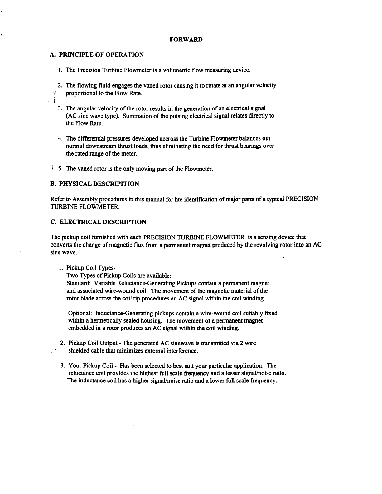
A. PRINCIPLE OF OPERATION
1.
The Precision Turbine Flowmeter
-’
2.
The flowing fluid engages the
i’
proportional to the Flow
4
3.
The
angular
velocity of the rotor results
(AC sine wave type).
Rate.
Summa tion of the pulsing electrical signal relates directly to
the Flow Rate.
FORWARD
is a volu me tric flo w measuring device.
vaned
rotor causing it to rotate at an angular velocity
in the generation of an electrical signal
4.
The differential pressures developed
accross
the Turbine Flow m eter balances out
nor m al do wnstrea m thrust loads, thus eli m inating the need for thrust bearings over
the rated range of the m eter.
i
5.
The
vaned
rotor is the only m oving part of the Flo wm eter.
B. PHYSICAL DESCRIPITION
Refer to Asse mb ly procedures in this m anual for hte identification of m ajor parts of a typical
PRECISION
TURBINE FLOW-METER.
C.
ELECTRICAL
The
pickup coil furnished with each PRECISION TURBINE FLO WM ETER is a sensing device that
converts the change of m agnetic flux fro m a per m anent m agnet produced by
DESCRIPTION
the
revolving rotor into an
AC
sine wave.
1. Pickup Coil
Types-
Two Types of Pickup Coils are available:
Standard: Variable Reluctance-Generating Pickups contain a per m anent m agnet
and associated w ire- wound coil.
The movement of the m agnetic m aterial of the
rotor blade across the coil tip procedures an AC signal w ithin the coil w inding.
Op tional: Inductance- Generating pickups contain a wire-wound coil suitably
futed
w ithin a her m etically sealed housing. The m ove m ent of a per m anent m agnet
em bedded in a rotor produces an AC signal within the coil winding.
2.
Pickup Coil Output
-
The generated AC
sinewave
is trans m itted via 2 w ire
shielded cable that m ini m izes external interference.
3. Your Pickup Coil
reluctance coil provides the highest
The inductance coil has a higher signal/noise ratio and a lo wer
-
Has been selected to best suit your particular application. The
full
scale frequency and a lesser signal/noise ratio.
full
scale frequency.
Page 5

PRE-INSTALLATION INSPECTION
Your PRECISION TURBINE FLOWMETER is a measuring instrument capable of providing you with
A.
high precision performance over a long period.
It should be treated with care and
not
subjected to rough
handling.
.
...
1
Unpack carefully and verify the information contained on the packing slip for
1’
proper MODEL Number, SERIAL Number, and CALIBRATION Data.
4
2.
Remove the instrument from the plastic packaging and remove the endfitting
protectors from the meter housing.
3.
Visually inspect the entire unit. Any visible damage should be reported to the
OMEGA Customer Service Department immediately.
4.
Replace the end fitting protectors and return the Flowmeter to its plastic
packaging. The unit may thus be stored indefmitely until installed.
\
1
I
INSTALLATION
A. GENERAL PROCEDURE
-
1. Meter Position
FLOWMETERS are normally calibrated in a horizontal attitude.
Best con-elation of calibration, therefore, occurs when installed and operated in
this position. Meters may, however, be operated satisfactorily in any position.
2. Flow Direction
-
ALL PRECISION TURBINE FLOWMETERS are marked “IN”
and “OUT” and have an arrow to indicate the proper direction of the flow.
Directional Flowmeters Excluded)
3. Meter Location
A.
Relative
-
-
When it is expected that flow will be intermittent, the meter should
not be mounted at a low point in the piping system. Solids which settle or
congeal in the meter may affect the meter performances.
B.
Tolerance to Mechanical Vibration
-
Although the PRECISION TURBINE
FLOWMETER is designed for rugged service, meter life may be increased by
location in a minimum vibration area.
C.
Tolerance to Electrical Interference
-
In order to achieve optimum electrical
signal output from the Flowmeter, consideration must be given to its isolation
from ambient electrical interference such as nearby motors, transformers, and
solenoids. (Section IV Maintenance Electrical)
4. System Pressure
A. Minimum Operation Pressure
-
-
A minimum operating pressure should be
maintained to preclude a change in the calibration factor due to various types
of two phase phenomena.
The minimum operating pressure is a function of the
vapor pressure of the fluid and the presence of other dissolved gases.
Maintenance of the system back pressure serves to avoid cavitation of fluid
separation.
(BI-
Page 6

B.
Maximum Meter Pressure
the size and type of connecting fitting used, and the materials of construction.
Consult the factory for specifications for your particular model.
B. PIPING
-
Safe working pressure for the flowmeter is determined by
-
r
1.
General Piping
the
flowmeter engages the angled blades of the turbine rotor.
of the rotor is a function of the fluid velocity and the blade angle engagement.
present in the fluid ahead of the meter can change the effective angle of the engagement
and, therefore, cause a deviation from the supplied calibration (done under controlled
conditions). Proper installation of the Flowmeter minimizes the harmful effects of fluid
swirl.
2.
The Metering Location
following the flowmeter is known as the “THE METERING LOCATION ”. Three typical
metering arrangements are described in the proceeding section of this manual. Each is
designed to minimize fluid swirl. A flow straightener is also shown and should be used
where installation does not allow the otherwise straight run of pipe upstream of the meter.
PLEASE NOTE:
the minimum distances between piping components that are recommended to eliminate
flow disturbances.
3. Meter-by-Pass
a valved by-pass around the Flowmeter. However, the by-pass connections are not to be
placed within the recommended metering run.
4.
Line Purge
line should be flushed thoroughly to minimize possible damage to the flowmeter from
foreign materials prior to installing the instrument.
Consideration
The required lengths of pipe are given in pipe diameters and represent
-
Where possible, such as in a new piping system, it is advisable to include
-
In a newly installed piping system, or one in which fittings have disturbed, the
As explained in the FORWARD, the fluid
Thus the rotational velocity
-
That section of the pipe immediately preceding, including, and
moving
through
Swirl
flow
C. ELECTRICAL CONNECTION
The Standard PRECISION TURBINE FLOWMETER pickup coil is designed to mate with an MS3
IOSL-4S
instrument in
unit ONLY, in order to minimize ground-loop and interface difficulties. The connection cable should be
located away from power lines whenever possible.
Precautions should be taken when removing, or installing the pickup coil. Any physical damage such as
bent threads or twisted Leads are not covered by the warranty.
connector. A two-wire shielded cable should be used to lead from the connector to the
use. The cable shield is connected (grounded) to the appropriate connector on the display
106-
electronic
Page 7

3 TYPICAL METERING RUN S
UPSTREAM
FITTlNG
PIPE
PRECEEDING
WIDE
OPEN VALVE (GA
SHARP RIGHT ANGLE BEND
(MITE
STRAIGHT RUN OF PIPE
IMMEDIATELY
METERING LOCATION.
TE
OR PLUG
O R
ELBOW)
RED
OR
)
P
i------*lOD------i
METERING LOCATION
+
N
-- -
fl
FILE:\OMEGA\OMEGA-P.DWG
PROCEEDING METERING
I
k---5D'
LONG RADIUS BENDS
OR
SMOOTH ELBOW
OR
TWO ELBOWS
OR
PARTIALLY OPEN
VALVES OF ANY TYPE.
STRAIGHTENER\
5D
--I
1.5,
*
MINIMUM LENGTHS OF STRAIGHT
PIPE REQUIRED EXPRESSED IN
Page 8

i’
i
-
Page 9

PICKUP COIL
.
1
2
FIGURE- 1
DISASSEMBLY
FOR BALL
1. INSERT EXTRACTION TOOL INTO END OF
CUP/CONE ASSY. ROTATE
CAREFULLY UNTIL IT IS DIRECTLY IN LINE
WlTH
ENTRY GROOMS. EXTRACT
PARALLEL
2. REMOVE BEARINGS AND ROTOR.
3. REMOVE OTHER CUP/CONE ASSY. AS
INDICATED IN STEP-l. LEAM SHAFT
INTACT.
4. REWEW PARTS FOR DAMAGE- CHECK
BEARINGS THOROUGHLY.
BEARING
PUWNG MOTION.
(
SLOYKY
STANDA
jCARBlDE
RD)
AND
WlTH
A
JOURNEL/
1
TYPICAL
PROCEDURE
FOR SLEEVED BEARIN
BEFORE BEGINNING- ASSEMBLY MUST GO BACK
TOGETHER THE EXACT WAY IT COMES OUT.
1. INSERT EXTRACTION TOOL INTO END OF
CLIP/CONE ASSY. ROTATE SLOW
CAREFULLY
WITH ENTRY GROOMS. EXTRACT
PARALLEL PULLING MOTION.
2. REMOM ROTCR CAREFUUY-BEARING
SHOULD NOT
3. REMOM OTHER CLIP/CONE ASSY. AS
INDICATED IN STEP-l. LEAVE SHAFT
INTACT.
4. REWEW PARTS FOR DAMAGE- CHECK
BEARING FOR CRACKS, CHIPS, AND
GROObES.
BEFORE
UNTlL
IT IS DIRECTLY IN LINE
REMOVED
Bi
CLEAN OFF ALL DEBRIS
REASSEUBLING.
AN HOUSING SHOWN:
FOR NPT AND SANITARY
G (
OPTIONAL
L
FRCM ROTOR.
Y AND
%lTH
)
NOTE: IF ANY PART APPEARS DAMAGED ‘DO NOT
REASSEMBLE”. CALL FLOW DEPT. FOR
1. INSERT CUP/CONE ASSY.
A
2. FROM OPPOSITE END OF HOUSING, INSERT
3. INSERT OTHER CONE/CLIP ASSY.
REASSEMBLY PROCEDURE
FOR
ENTRY GROOMS AS FAR AS IT
WlTH
EXTRACTION TOOL ROTATE CLIP/CONE
ASSY. SLOLY IN THE POSITION
IN FIG. 2.
BEARING. (CLOSED
INSERT ROTOR
NOTE: BE SURE THE ‘IN’ MARK ON THE
STEP
1.
BEARING
B
ALL
WITH
ROTOR COINCIDES
MARK ON
HOUSNG.
(STANDARD)
VtlTH
DOkN) CAREFULLY
SlDE
OTHER BEARING IN TACT.
THE
wl7-l
OUTSIDE OF ME
INSTRUCTlONS
SHAFT INTO
WlLL
GO.
IUUSTRATED
ThE
‘IN’
REPEAnNG
FOR
NOTE: IF ANY PART APPEARS DAMAGED ‘DO NOT
REASSEMBLE ’. CALL FLOW DEPT. FOR
1. INSERT CUP/CONE ASSY.
ENTRY GROOMS AS FAR AS IT
klTH
ASSY.
IN FIG. 2.
2. FROM OPPOSITE END OF HOUSING, INSERT
ROTOR CAREFULLY.
3. INSERT OTHER CONE/CUP ASSY.
STEP
4. FCR
BEST
Page 10

“..
F-2
G
H
CCNSUL?
AND
I
IolAFl
PICUUP
1
IC-RINCun
FACTORY
INSTAKATION.
CGiL
FMI
O-RING MATERIALS
I
1
I
1
I
1)
2)
3)
4)
INSERT
ME FACE
REMOM
RmOM
MECX
A.
CHECK
B.
MCENT.
ARING
8f
EAU
SCREW
nit of
plm.
‘MM A
x?mER
FCR
INTO
REMOM
DAMACE.
THCRCUWLY.
CRAG6
SCFW
4-40
BEARINGS AND ROTOR
THE
NJ.
PARTS FOR REWEW
BEARINGS
0-RING
(sTANDA~?~)
scRF1v
PLUG
DWXR,
TMED
THE
O?liER
~tm
OF
FROM
- I? IS NO? NECESSARY TO
RE%.ACf
MCKS.
ANC
DISASSEMBLY PROCEDURE
1)
BlRAC?
HCGS
Hwwc.
IF
ON
2) INSERT
3)
4)
WlH
A
4-40
ff
THE
FACE
REMOX
ME
REMOK
TO
NECESSARY TO
AAL
PARTS
RCJIEW
ME%
A.
iXE~~?+lNC
8.
smw
SCRF#
THE
THE
BEARING
REMM
SURUICS
mfu~~
REMOK
INTO
RETAINa
FR!?U
lHE
DAMACE.
FCR
lH’XG’JGHL.Y.
CRAW
FOR
(OPTICNAL)
SCXW
PLUG.
SCREW DRIVER.
OMR
Cf
EKlRAC?
AN0
ASSEMBLY
THE
ROTOR) I? IS NO?
3lAFI.
AN0
NICKS. REPLACE
D1E
(DO NO? ROTW/BE47lNG
TA’PED
FRON
HOLES
HOUSING.
All’EMP?
lF
REASSEMBLY PROCEDURE
(STA~~OARO)
BEARING
appwn
fcf
ffl
WOK
damaged,
hstluctic?l¶.
ROTOR
4-40 SCREW.
AN0
DO NOT
!NSERT
ROTOR
RfASSWLE,
lN
HCUSM.
BALL
NOTE: If my
ffl
INSTAll.
1)
2) INSERT
3)
pmt
Depl
now can
WRINGS
RE?AItXR.
SCREW !N SC-W PLUG.
Page 11

ow.
CONSUL? FACTORY
lNS?AL!A?iCN
AND
FOR
O-RING
YATtRlAlS
1)WlH
2)lNSERT
ME
3)RCIOM
RMFN
4)
A.
8.
~;;&T+RINC
B
ALL
SCREWOffIVER.REUOM
A
c-40
FACf
OF ME
EEAR!NGS
AND
ALL
PARTS FCR
Ct?ECX
BEARINGS THOROUGHLY.
FCR
BEARING
OTtiER
RO?CJl/SHAFT~W
DAMAGE.
Ci%u(S
(STANDARD)
SClfEN'puIc.
TAPPED
THE
Of SCREW INTO
FROU
NICKS
AND
REPLACE IF
DISASSEMBLY PROCEDURE
l)WlHASCXWCRi'.FR.REiiOMS'X~PLL'~
HUfS
HCUSNC.
RE?AlNW AND EXTRACT
CM
2)HSER?t4OSCREWiNmo~ffTHE?AMDHoLEsON
I
3)WOX
I
4)RMEW
CT
nlE
ACHE!XBUi(lNCS
8.
ME
FACE
RO?oR/8EARlNC
All PARTS
C-lEDHET~RINC
AND EXTRACT
ASSEUBLY.
OAMAG&
IHOR'XU4LY.
(C+ ‘nONti)SLEMD
BEARING
REiM
FOR
FCR CRACKS AND NICKS.
FROM
HCUSlNC.
REPLACE
REASSEMBLY PROCEDURE
IfonypartoppmndaqsQ
cdl
1) INSERT
3)lNSERTRETAiNER
IN SCREW
!F
4)
hr
DepL
flow
6EMlNC INTO BEARING
ASSEMBLY
Ah0
PLUG.SCRE'#
inrtnrcticm.
WP.
RFXOK
4-M
DONOTREASSEMELE.
NOTE
BEARING.
AND 2)lNSER?RO?OR/SfAFT
SGXW.
Page 12

OMEGA ENGINEERING, INC. warrants this unit to be free of defects in materials and workmanship for a
(1)
period of 13 months from date of purchase. OMEGA Warranty adds an additional one
period to the normal one (1) year product warranty to cover handling and shipping time.
ensures that OMEGA ’s customers receive maximum coverage on each product.
If the unit should malfunction, it must be returned to the factory for evaluation.
Service Department will issue an Authorized Return (AR) number immediately upon phone or
request. Upon examination by OMEGA, if the unit is found to be defective it will be repaired or replaced at
no charge. OMEGA ’s WARRANTY does not apply to defects resulting from any action of the purchaser,
including but not limited to mishandling, improper interfacing, operation outside of design limits,
improper repair, or unauthorized modification. This WARRANTY is VOID if the unit shows evidence of
having been tampered with or shows evidence of being damaged as a result of excessive corrosion; or
current, heat, moisture or vibration; improper specification; misapplication; misuse or other operating
conditions outside of OMEGA’s control. Components which wear are not warranted, including but not
limited to contact points, fuses, and
OMEGA
OMEGA neither assumes responsibility for any omissions or errors nor assumes liability for any
damages that result from the use of its products in accordance with information provided by
OMEGA, either verbal or written. OMEGA warrants only that the parts manufactured by it will be
as specified and free of defects.
REPRESENTATlONS
TDl.E,:AND
AND
LlABIm
OMEGA with respect to this order, whether based on contract, warranty, negligence,
indemnification, strict liability or otherwise, shall not exceed the purchase price of the
component upon which liability is based. In no event shall OMEGA be liable for
consequential, incidental or special damages.
CONDITIONS: Equipment sold by OMEGA is not intended to be used, nor shall it be used: (1) as a “Basic
Component” under 10 CFR 21 (NRC), used
applications or used on humans. Should any Product(s) be used in or with any nuclear installation or
activity, medical application, used on humans, or misused in any way, OMEGA assumes no responsibility
.,
as set forth in our basic WARRANTY/DISCLAIMER language, and additionally, purchaser will indemnify
OMEGA and hold OMEGA harmless from any liability or damage whatsoever arising out of the use of the
Product(s) in such a manner,
is
pleased to offer suggestions on the use of its various products.
OF ANY KIND WHATSOEVER, EXPRESSED OR IMPUED,
IMPUED
AU
FlTNESS
FOR A PARTICULAR PURPOSE ARE HEREBY DISCLAIMED. LIMITATION OF
The remedies of purchaser set forth herein are exclusive and the total liability of
WARRANTlES
triacs.
OMEGA MAKES NO
INCLUDING ANY WARRANTY OF
in or with any nuclear installation or activity; or
OTHER WARRANTIES OR
OMEGA’S
MERCHANTABIUTY
month grace
However ,
EKCEPT
(2)
This
Customer
written
THAT OF
in
medical
-NTY
.- L
_v_->*i
Direct all warranty and repair requests/inquiries to the OMEGA Customer Service Department. BEFORE
RETURNING ANY PRODUCT(S) TO OMEGA, PURCHASER MUST OBTAIN AN AUTHORIZED RETURN
(AR) NUMBER FROM OMEGA ’S CUSTOMER SERVICE DEPARTMENT (IN ORDER TO AVOID
PROCESSING DELAYS). The assigned AR number should then be marked on the outside of the return
package and on any correspondence.
The purchaser is responsible for shipping charges, freight, insurance and proper packaging to prevent
breakage in transit.
FOR
following information available BEFORE
contacting OMEGA:
1.
PO. number under which the product was
PURCHASED,
Model and serial number of the product under
2.
warranty, and
Repair instructions and/or specific problems
3.
relative to the product.
OMEGA’s policy is to make running changes, not model changes, whenever an improvement is possible. This affords
our customers the latest in technology and engineering.
OMEGA is a registered trademark of OMEGA ENGINEERING,
@I
Copyright 1996 OMEGA ENGINEERING, INC. All rights reserved. This document may not be copied, photocopied,
reproduced, translated, or reduced to any electronic medium or machine-readable form, in whole or in part, without prior
written consent of OMEGA ENGINEERING, INC.
‘,_~.
RETURNS, please have the
RETURN REQUESTS
/
INQUIRIES
JUON-WAqBANTY REPAIRS, consult OMEGA
FOR
for current repair charges. Have the following
information available BEFORE contacting OMEGA:
PO. number to cover the COST
of the repair,
Model and serial number of product, and
Repair instructions and/or specific problems
relative to the product.
INC.
. .
.-
.
-
‘1..
-’
Page 13

I
mere
Do
Find Everything I Need for
Process Measurement and Control?
OMEGA...Of
Course!
TEMPERATURE
Ii3
Thermocouple, RTD
@
Wire: Thermocouple, RTD
&
0 Calibrators
0 Recorders, Controllers
0 Infrared Pyrometers
Ice Point References
Thermistor Probes,
&
Thermistor
&
Process Monitors
Connectors, Panels
&
PRESSURE, STRAIN AND FORCE
&
0
Transducers
0
Load Cells
0
Displacement Transducers
0 Instrumentation
Strain Gauges
&
Pressure Gauges
&
Accessories
FLOW/LEVEL
&
ia
Rotameters, Gas Mass Flowmeters
0 Air Velocity Indicators
/
0
Turbine
Totalizers
0
Paddlewheel Systems
&
Batch Controllers
Flow Computers
pH/CONDUCTMTY
&
0
0
Benchtop/Laboratory Meters
0
Controllers, Calibrators, Simulators
&
Conductivity Equipment
pH
0’
Industrial
AccessoriespH Electrodes, Testers
&
Pumps
&sembfies
&
M2728/0297
DATA
0
Data Acquisition
0 Communications-Based Acquisition Systems
0 Plug-in Cards for Apple, IBM
0 Datalogging Systems
0 Recorders, Printers
ACQUlSlTlON
&
Engineering Software
&
Plotters
&
Compatibles
HEATERS
@’
Heating Cable
&
0 Cartridge
0 Immersion
0 Flexible Heaters
0 Laboratory Heaters
Strip Heaters
&
Band Heaters
ENVIRONMENTAL
MONITORING AND CONTROL
&
Metering
0
Refractometers
0
Pumps
Air, Soil
E
Industrial Water
0
pH,
Conductivity
0
Control Instrumentation
&
Tubing
&
Water Monitors
&
Wastewater Treatment
&
Dissolved Oxygen Instruments
 Loading...