

Page 1
omega.com
e-mail: info@omega.com
For latest product manuals:
omegamanual.info
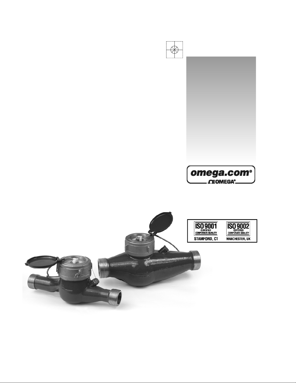
FTB8000A SERIES
Pulse Mete r
Shop online at
User’s Guide
Page 2

Servicing North America:
U.S.A.: One Omega Drive, P.O. Box 4047
ISO 9001 Certified
Stamford, CT 06907-0047
TEL: (203) 359-1660 FAX: (203) 359-7700
e-mail: info@omega.com
Canada: 976 Bergar
Laval (Quebec) H7L 5A1, Canada
TEL: (514) 856-6928 FAX: (514) 856-6886
e-mail: info@omega.ca
For immediate technical or application assistance:
U.S.A. and Canada: Sales Service: 1-800-826-6342 / 1-800-TC-OMEGA
®
Customer Service: 1-800-622-2378 / 1-800-622-BEST
®
Engineering Service: 1-800-872-9436 / 1-800-USA-WHEN
®
TELEX: 996404 EASYLINK: 62968934 CABLE: OMEGA
Mexico: En Espan˜ol: (001) 203-359-7803 e-mail: espanol@omega.com
FAX: (001) 203-359-7807 info@omega.com.mx
Servicing Europe:
Benelux: Postbus 8034, 1180 LA Amstelveen, The Netherlands
TEL: +31 (0)20 3472121 FAX: +31 (0)20 6434643
Toll Free in Benelux: 0800 0993344
e-mail: sales@omegaeng.nl
Czech Republic: Frystatska 184, 733 01 Karviná, Czech Republic
TEL: +420 (0)59 6311899 FAX: +420 (0)59 6311114
Toll Free: 0800-1-66342 e-mail: info@omegashop.cz
France: 11, rue Jacques Cartier, 78280 Guyancourt, France
TEL: +33 (0)1 61 37 2900 FAX: +33 (0)1 30 57 5427
Toll Free in France: 0800 466 342
e-mail: sales@omega.fr
Germany/Austria: Daimlerstrasse 26, D-75392 Deckenpfronn, Germany
TEL: +49 (0)7056 9398-0 FAX: +49 (0)7056 9398-29
Toll Free in Germany: 0800 639 7678
e-mail: info@omega.de
United Kingdom: One Omega Drive, River Bend Technology Centre
ISO 9002 Certified
Northbank, Irlam, Manchester
M44 5BD United Kingdom
TEL: +44 (0)161 777 6611 FAX: +44 (0)161 777 6622
Toll Free in United Kingdom: 0800-488-488
e-mail: sales@omega.co.uk
OMEGAnet®Online Service Internet e-mail
omega.com i n f o @ o m e g a . c o m
It is the policy of OMEGA Engineering, Inc. to comply with all worldwide safety and EMC/EMI
regulations that apply. OMEGA is constantly pursuing certification of its products to the European New
Approach Directives. OMEGA will add the CE mark to every appropriate device upon certification.
The information contained in this document is believed to be correct, but OMEGA accepts no liability for any
errors it contains, and reserves the right to alter specifications without notice.
WARNING: These products are not designed for use in, and should not be used for, human applications.
Page 3
FTB8000A - SERIES
Pulse Meter Instructions
General Information
FTB8000A-Series meters use the multi-jet principle,
which has been an internationally-accepted standard
for many years. This type of meter is known for its wide
range, simplicity, and accuracy in low-quality water. The
impeller is centered in a ring of jets, with inlet jets on
one level and outlet jets on another. A gear train drives
the register totalizer dials. For pulse output, one of the
dials is replaced by a gear, which turns a magnet that
is detected by an encapsulated sensor threaded into
the outside of the lens. Pulse rate is determined by the
gear and the dial on which the gear is placed.
Mechanically, all FTB8000A-Series meters are the
same. The difference between -PR, -PT and Standard
meters is in the sensor. -PR meters use a solid-state,
long-lasting Hall-effect sensor, which requires power.
-PT meters use a two-wire reed switch. They provide a
dry contact closure and do not require power. Standard
meters totalize only and do not have a sensor.
Specications
Materials
Case Cast bronze
Internals Engineered thermoplastic
Magnet Ceramic permanent
Temperature 105° F, 40° C
Max. Pressure 150 PSI operating
Accuracy 1-1/2% of reading
Sensor
-PR Solid state
-PT Reed switch
Max. Current
-PR 20 mA
-PT 50 mA
Max. Voltage
-PR 24 VDC
-PT 24 VDC or 24 VAC
Sensor Power -PR Minimum 6 mA at 12 VDC
Cable Length 18 ft. standard, 2,000 ft. max.
Flow Rates (GPM):
3/4" 1" 1-1/2" 2"
Minimum 0.22 0.44 0.88 1.98
Features
Either -PR or -PT sensor
threads into lens without
removing top
Cast bronze body-
meets AWWA
specications
Maximum 22 52 88 132
Union end couplings for
easy service
Page 1
Page 4

(BLACK) Power (-)
(BROWN) Common
(WHITE) Signal
(WHITE) N.O.
(RED) Power (+) 6-24 VDC
sensor connection
MDR sensor connection
MDE
Installation
WARNING
DO NOT INSTALL
meter in overhead
Indoor piping or where
leakage
may cause damage
These water meters are not
recommended for installation
indoors or anywhere leakage
may cause damage.
the lens. The sensor turns on and off once each time
the magnet passes under it. Sensors are designed for
electronic control loads, and should not be used to switch
power loads or line voltages. See maximum current and
voltage ratings, under Specications.
Maintenance
All service should be performed by authorized distributor or factory to maintain the integrity of the protective
tamper-proof wire-and-seal.
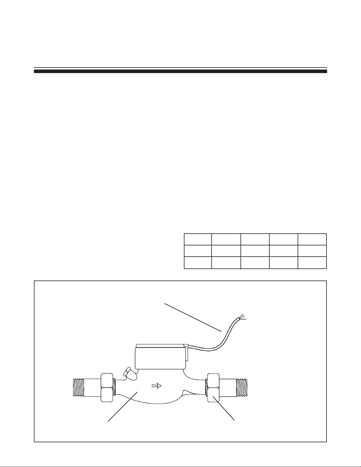
Position. FTB8000A-Series meters should be installed
horizontally with the register up. Vertical mounting will
result in some degree of under-measurement and shortened life of the bearings.
Couplings. Couplings are included with each meter.
These provide male NPT threads the same nominal
size as the meter. The threads on the end of the meter
are IPS straight threads one size bigger than the meter
size. It is possible to thread a standard pipe coupling
directly onto the meter for close coupling, but the meter
couplings are much preferable because they provide a
union connection for meter service. Be sure to use the
included gasket between the end of the meter and the
coupling.
Inlet Conditions. No upstream straight pipe is required.
A strainer is built in to protect from solids, and should be
periodically cleaned.
Air Bleed. When the meter is rst installed, trapped air
should be removed. To do this, loosen the meter couplings slightly and rotate the meter to an inverted posi-
tion. Allow water to ow, then rotate the meter back
to an upright position and tighten.
Connections. -PR and -PT sensors are supplied with
a color coded output cable. See the diagram for color
codes and polarity.
Pulse Output. Both -PR and -PT sensors respond to
a magnet which rotates on the face of the meter under
Inlet Strainer. Clean the strainer yearly, or as required,
depending on water condition. Pull out the strainer or
backush the meter to loosen trapped particulates.
Calibration. Meters used for billing or billing exemption may be regulated by state or local authorities. New
meters are factory-tested to meet the AWWA C-708
Multi-Jet Meter accuracy specication. Some states
require retesting at various intervals, typically eight years
for 3/4" meters, six for 1", and four for 1-1/2" and 2". Meters used for control should be tested every 5-10 years.
Testing can be done by local meter shops authorized for
this purpose, or can be done by the factory. For tracking purposes, please obtain an Authorized Return (AR)
number before shipping to Omega.
Internal Parts Replacement. All of the internal parts
of an FTB8000A-Series meter lift out as a unit, after the
top has been unscrewed. The lens can then be removed
and the internal assembly lifted out. If necessary, turn
the meter upside down and tap one end lightly on a
countertop to loosen the internals. The three pieces of
the assembly can be separated by hand.
Breakage in a relatively-new meter is almost always due
to excessive ow. Compare maximum ow with the ow
rating table.
Changing Pulse Rates. After removing the meter top,
lift off the center magnet to expose the gears. If the only
change required is moving the drive gear (for example
from one gallon/pulse to ten gallons/pulse), gently pull
the drive gear off its shaft. Remove the pointer on the
target shaft and push the drive gear onto the target shaft
as far as it will go. Put the pointer on the vacant shaft
and push on.
Page 2
If a different gear set is required, follow the same procedure, replacing rather than moving the drive gear. To
install a drive gear on another shaft, remove the pointer
and then press the gear down until it bottoms. Use the
pulse rate chart to determine the position.
Page 5

3/4" - 10 gallons/pulse
Pulse
Rate
Drive Gear
Position
Gear Set
(X...)
20 P/G
*
2
10 P/G 1
2 P/G X0.1 2
1 P/G X0.1 1
3/4"
5 G/P X1 2
10 G/P X1 1
50 G/P X10 2
100 G/P X10 1
20 P/G
*
2
10 P/G
*
1
2 P/G X0.1 2
1"
1-1/2"
2"
1 P/G X0.1 1
5 G/P X1 2
10 G/P X1 1
50 G/P X10 2
100 G/P X10 1
2 P/G 2
1 P/G 1
5 G/P X1 2
10 G/P X1 1
50 G/P X10 2
100 G/P X10 1
500 G/P X100 2
1000 G/P X100 1
2 P/G 2
1 P/G 1
5 G/P X1 2
10 G/P X1 1
50 G/P X10 2
100 G/P X10 1
500 G/P X100 2
1000 G/P X100 1
* Unlabeled position
*
*
*
*
*
Standard
(X1) gearset
move
gear to
match
X1 Drive gear on
position
*Unlabelled position
3/4" - 50 gallons/pulse
X2 gearset
X10 Drive
gear on
position
3/4" - 1 gallon/pulse
X2 gearset
X0.1 Drive gear
on position
Page 3
Page 6

FTB8000A-Series
Parts
reed switch
w/cable
cap screw
(over)
calibration plug
(under)
strainer
slip ring
pair
lens
register
assembly
O-ring
multi-jet
assembly
FTB8000A-SERIES PARTS
Part # FOR ALL SIZES
30387 Gear Assembly, x1
30342 Gear Assembly, x2
30290 Hinge Pin
30293 Lens, Glass
30289 Lid
30296 O-ring
30300 Pickup, Reed Switch, 12' Cable
30346 Pickup, Solid State, 12' Cable, MDE
30292 Slip Ring (pair)
Part # FOR 3/4" METERS
16125 Calibration Plug
16105 Cap Screw for Calibration Plug
30381 Coupling Assembly (2 required)
30416 Coupling Gasket (2 required)
30311 Multi-jet Assembly
30308 Register Assembly
30479 Strainer
Part # FOR 1" METERS
16125 Calibration Plug
16105 Calibration Plug Cap Screw
30382 Coupling Assembly (2 required)
30417 Coupling Gasket (2 required)
30297 Drive Magnet
30323 Multi-jet Assembly
30321 Register Assembly
30480 Strainer
Part # FOR 1-1/2" METERS
30303 Calibration Plug
30305 Calibration Plug Cap Screw
30383 Coupling Assembly (2 required)
30418 Coupling Gasket (2 required)
30297 Drive Magnet
30304 Gasket
30332 Multi-jet Assembly
30330 Register Assembly
30481 Strainer
Part # FOR 2" METERS
30303 Calibration Plug
30305 Calibration Plug Cap Screw
30384 Coupling Assembly (2 required)
30419 Coupling Gasket (2 required)
30297 Drive Magnet
30304 Gasket
30326 Multi-jet Assembly
30328 Register Assembly
16240 Strainer
Page 4
Page 7

WARRANTY/DISCLAIMER
OMEGA ENGINEERING, INC. warrants this unit to be free of defects in materials and workmanship for a
period of 13 months f rom date of purchase. OMEGA’s WARRANTY adds an additional one (1) month
grace period to the normal one (1) year product warranty to cover handling and shipping time. This
ensures that OMEGA’s customers receive maximum coverage on each product.
If the unit malfunctions, it must be re t u rned to the factory for evaluation. O M E G A’s Customer Serv i c e
D e p a rtment will issue an Authorized Return (AR) number immediately upon phone or written re q u e s t .
Upon examination by OMEGA, if the unit is found to be defective, it will be re p a i red or replaced at no
c h a rge. O M E G A’s WARRANTY does not apply to defects resulting from any action of the purc h a s e r,
including but not limited to mishandling, improper interfacing, operation outside of design limits,
i m p roper re p a i r, or unauthorized modification. This WARRANTY is VOID if the unit shows evidence of
having been tampered with or shows evidence of having been damaged as a result of excessive corro s i o n ;
or current, heat, moisture or vibration; improper specification; misapplication; misuse or other operating
conditions outside of OMEGA’s c o n t rol. Components in which wear is not warranted, include but are not
limited to contact points, fuses, and triacs.
OMEGA is pleased to offer suggestions on the use of its various products. However,
OMEGA neither assumes responsibility for any omissions or errors nor assumes liability for any
damages that result from the use of its products in accordance with information provided by
OMEGA, either verbal or written. OMEGA warrants only that the parts manufactured by the
company will be as specified and free of defects. OMEGA MAKES NO OTHER WARRANTIES OR
R E P R E S E N TATIONS OF ANY KIND WHATSOEVER, EXPRESSED OR IMPLIED, EXCEPT THAT OF
TITLE, AND ALL IMPLIED WARRANTIES INCLUDING ANY WARRANTY OF MERCHANTA B I L I T Y
AND FITNESS FOR A PA RTICULAR PURPOSE ARE HEREBY DISCLAIMED. LIMITATION OF
L I A B I L I T Y: The remedies of purchaser set forth herein are exclusive, and the total liability of
OMEGA with respect to this ord e r, whether based on contract, warr a n t y, negligence,
indemnification, strict liability or otherwise, shall not exceed the purchase price of the
component upon wh ich lia bility is ba sed. I n no even t s hal l O MEGA b e liab le for
consequential, incidental or special damages.
CONDITIONS: Equipment sold by OMEGA is not intended to be used, nor shall it be used: (1) as a “Basic
Component” under 10 CFR 21 (NRC), used in or with any nuclear installation or activity; or (2) in medical
applications or used on humans. Should any Product(s) be used in or with any nuclear installation or
a c t i v i t y, medical application, used on humans, or misused in any way, OMEGA assumes no re s p o n s i b i l i t y
as set forth in our basic WA R R A N TY/ DISCLAIMER language, and, additionally, purchaser will indemnify
OMEGA and hold OMEGA h a rmless from any liability or damage whatsoever arising out of the use of the
P roduct(s) in such a manner.
RETURN REQUESTS/INQUIRIES
Direct all warranty and repair requests/inquiries to the OMEGA Customer Service Department. BEFORE
RETURNING ANY PRODUCT(S) TO OMEGA, PURCHASER MUST OBTAIN AN AUTHORIZED RETURN
(AR) NU M B ER F ROM OMEGA’S CU S TO M E R S E RVICE DEPA RT M E N T ( IN ORDER TO AV O I D
PROCESSING DELAYS). The assigned AR number should then be marked on the outside of the return
package and on any correspondence.
The purchaser is responsible for shipping charges, freight, insurance and proper packaging to prevent
breakage in transit.
FOR WARRANTY RETURNS, please have the
following information available BEFORE
contacting OMEGA:
1 . P u rchase Order number under which the pro d u c t
was PURCHASED,
2. Model and serial number of the product under
warranty, and
3. Repair instructions and/or specific problems
relative to the product.
FOR NON-WARRANTY REPAIRS,
consult OMEGA
for current repair charges. Have the following
information available BEFORE contacting OMEGA:
1. Purchase Order number to cover the COST
of the repair,
2. Model and serial number of the product, and
3. Repair instructions and/or specific problems
relative to the product.
OMEGA’s policy is to make running changes, not model changes, whenever an improvement is possible. This affords
our customers the latest in technology and engineering.
OMEGA is a registered trademark of OMEGA ENGINEERING, INC.
© Copyright 2005 OMEGA ENGINEERING, INC. All rights reserved. This document may not be copied, photocopied,
reproduced, translated, or reduced to any electronic medium or machine-readable form, in whole or in part, without the
prior written consent of OMEGA ENGINEERING, INC.
Page 8

W h e re Do I Find Eve rything I Need for
P rocess Measurement and Control?
OME GA…Of Cours e !
Shop online at omega.com
T E M P E R AT U R E
Thermocouple, RTD & Thermistor Probes, Connectors, Panels & Assemblies
Wire: Thermocouple, RTD & Thermistor
Calibrators & Ice Point References
Recorders, Controllers & Process Monitors
Infrared Pyrometers
PRESSURE, STRAIN AND FO RC E
Transducers & Strain Gages
Load Cells & Pressure Gages
Displacement Transducers
Instrumentation & Accessories
F LOW / L E V E L
Rotameters, Gas Mass Flowmeters & Flow Computers
Air Velocity Indicators
Turbine/Paddlewheel Systems
Totalizers & Batch Controllers
p H / C O N D U C T I V I TY
pH Electrodes, Testers & Accessories
Benchtop/Laboratory Meters
Controllers, Calibrators, Simulators & Pumps
Industrial pH & Conductivity Equipment
DATA AC Q U I S I T I O N
Data Acquisition & Engineering Software
Communications-Based Acquisition Systems
Plug-in Cards for Apple, IBM & Compatibles
Datalogging Systems
Recorders, Printers & Plotters
H E AT E R S
Heating Cable
Cartridge & Strip Heaters
Immersion & Band Heaters
Flexible Heaters
Laboratory Heaters
E N V I RO N M E N TA L
M O N I TORING AND CONTRO L
Metering & Control Instrumentation
R e f r a c t o m e t e r s
Pumps & Tubing
Air, Soil & Water Monitors
Industrial Water & Wastewater Treatment
pH, Conductivity & Dissolved Oxygen Instruments
LT-12001-B
M-3958/0505
 Loading...