

Page 1
a3
2;
@
@
fr
@
a
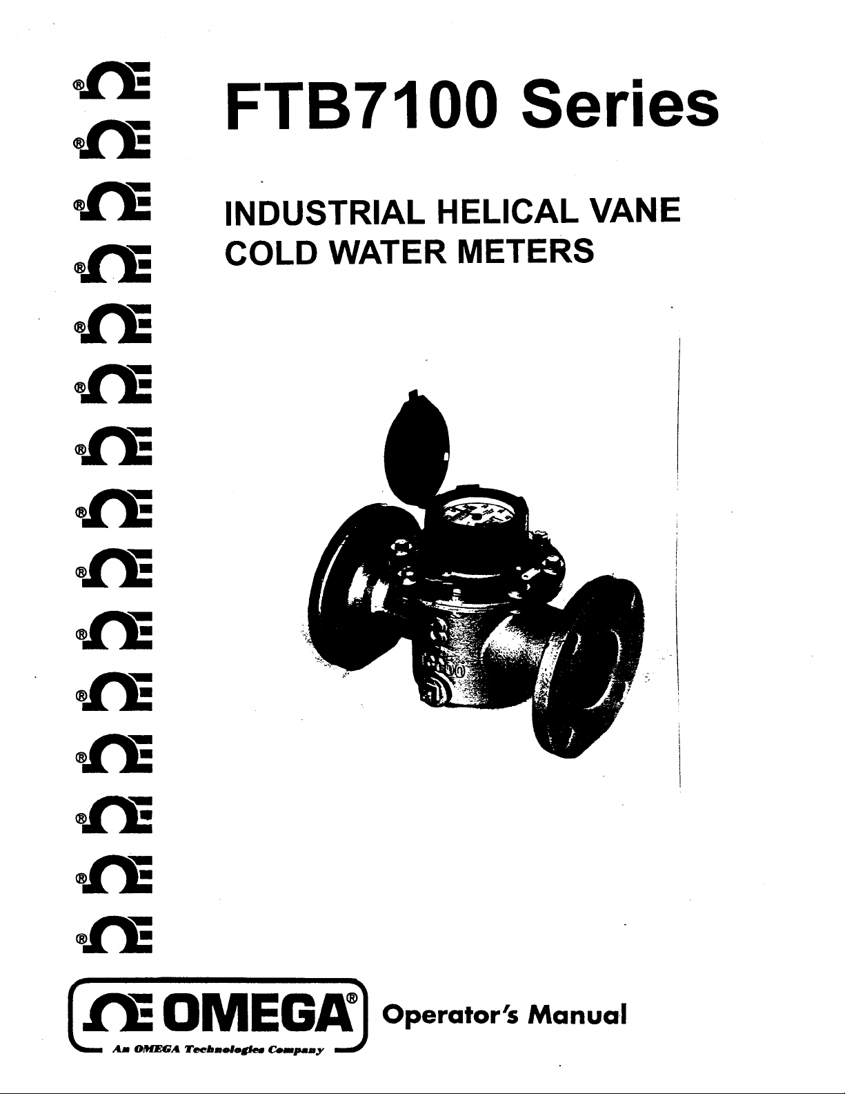
FTB7100
Series
I
INDUSTRIAL HELICAL VANE
I
COLD WATER METERS
Page 2
WARRANTY
OMEGA warrants this unit lo be free of defects in materials and workmanship and to give
date of purchase. OMEGA Warranty adds an
and shipping time. This ensures that our customers receive maximum coverage on each
returned to the factory for evaluation. Our Customer Service Department will issue an
or written request. Upon examination by OMEGA, if the unit is found to be defective
this WARRANTY is VOID if the unit shows evidence of having been tampered
corrosion; or current. heat, moisture or vibration; improper specification; misapplication; misuse or other
OMEGA ’s control. Components
THESE UNITS ARE INHERENTLY DANGEROUS AND ARE INTENDED TO BE INSTALLED AND USED ONLY BY QUALIFIED
PERSONNEL. NO WARRANTY EXTENDED HEREIN WILL APPLY IF SUCH UNIT IS INSTALLED OR USED BY UNQUALIFIED
PERSONNEL.
IMPLIED, INCLUDING BUT NOT
PARTICULAR PURPOSE. OMEGA ENGINEERING, INC. IS NOT RESPONSIBLE
EQUIPMENT, WHETHER DIRECT, INDIRECT, INCIDENTAL, SPECIAL OR CONSEQUENTIAL, WHICH THE PURCHASER MAY
EXPER IENCE
OFTH IS
NOT EXCEED THE PURCHASE PRICE PAID BY THE PURCHASER TO OMEGA ENGINEERING, INC. FOR THE UNIT OR UNITS OR
EQUIPMENT DIRECTLY AFFECTED BY SUCH BREACH.
EVERY PRECAUTION FOR ACCURACY HAS BEEN
ENGINEERING, INC. NEITHER ASSUMES RESPONSIBILITY FOR ANY OMISSIONS OR ERRORS THAT MAY APPEAR NOR ASSUMES
LIABILITY FOR ANY DAMAGES THAT RESULT FROM THE USE OF THE PRODUCTS IN ACCORDANCE WITH THE INFORMATION
CONTAINED IN THE MANUAL.
THERE
ARE NO WARRANTIES
AS A RESULT
AGREEMENT BY OMEGA ENGINEERING, INC. OR ANY BREACH OF ANY WARRANTY BY OMEGA ENGINEERING, INC. SHALL
which
wear or
OFTHE
addiiai
one (1) month grace period to the normal one (1)
e
damaged by misuse are not
which
EXCEPT
LlMlTED
TO THE IMPLIED
INSTALLATION OR USE
AS STATED HEREIN. THERE
TAKEN
with
or shows evidence Of
WARRANTlES
FOR
OFTHE PRODUCT. THE BUYER ’S
IN THE PREPARATION
@isfaCtOrY
Authoked
it
will be
warmnt&.
ARE
OF MERCHANTABILITY AND OF FITNESS FOR A
ANY
service for a period of 13 months from
prpduc!
product.
year
If
the
(AR)
Revm
reparred
or
being
These include contact
NO OTHER WARRANTIES, EXPRESSED OR
DAMAGES OR LOSSES
SOLE REMEDY FOR
OF
THIS MANUAL, HOWEVER, OMEGA
warranty to
Unit
should
nUmber
immediately upon phone
replaced
at no charge. However,
dame
as a
OPeratw conditions outside of
Point%
?xfe!
handling
It
malfunction,
result
CAUSEDTO
must be
Of excessive
fuses, and ttiacs.
OTHER
ANY BREACH
z
AnoMEa
One Omega
Stamford, Connecticut
Call OMEGA
Sa les :
Cus tome r Serv ice:
Eng ineering Assistance:
In ternational: (203)
EASYL INK : 62966934 TELEX : 996404
lbcmologJesconrpaqy
Drive, Box 4047
Of39074C47
Toll
Free
I-S OO -TGOMEGA
I
14300-82-66342
1-800-622-2378
1-600472-9436
369-1660
1400-622-BEST
/
1-6OO-lJS4- WHEN
I
CABLE : OMEGA
FAX:
(203) 3597700
Return Requests/Inquiries
Direct
all warranty and repair
l-800-622-2378; International
THE
OMEGA CUSTOMER SERVICE DEPARTMENT
requests/inquiries
(203) 3541660.
designated AR number should then be marked on the outside of the
To avoid processing delays, also please be sure to include:
1. Returnee ’s name, address, and phone number.
2. Model and Serial numbers.
3.
Repair instructions.
OMEGA ’s policy is to make running changes, not mode l changes, whenever an i mp rove men t is possible. That
customers
get the latest in technology and engineering.
to OMEGA Customer Service Department, telephone number
BEFORE RETURNING ANY INSTRUMENT, PLEASE
CONTACX
TO OBTAIN AN AUTHORIZED RETURN (AR) NUMBER. The
return
package.
way our
OMEGA@
0
Copyright
is a registered trade ma rk of OMEGA ENG INEER ING , I NC .
1
OMEGA ENG INEER ING , I NC . All rights reserved including illustrations. Nothing in this manua l may be
1%
reproduced in any manne r, either who lly or in part for any purpose whatsoever without written per m ission fro m
OMEGA ENG INEER ING , I NC .
Printed in
U.S .A .
M1100 /0191
Page 3
5”
ThiiLI%QF
CONTENTS
FTji7000
TURBINE
METERWATER
SECTION
SECTION 1
SECTION 2
SECTION
3
SECTION 4
SECTION 5
SECTION 6
SECTION 7
PAffE
INTRODUCTION
AVAILABLE MODELS
INSTALLATION
3.1
Unpacking
3.2 Installation
START UP PROCEDURE
SPECIFICATIONS
OPTIONS
,...~,,~..~,.,..,..,,,,,~,,,...
I............,,.,...,......
. . . . . . . . . . . . . . . . . . . ..**........
,....,...,,,......I.,.......
1.1*..,,..*..,,...*..*...
,...,,,.........*.....*..
,.,..,,.,.,~.,..~.~..........
,......,.,,,...,,,,,...,,,...,,,....
DIMENSIONAL DRAWINGS....................... 4
1
1
1
1
2
2
2
3
‘i
Page 4

SECTION 1 INTRODUCTION
OMEGRFTB7000
The
made of iron) is designed for high volume,
passes
through the meter without a change in flow direction, driving a
helical vane motor in direct proportion to the quantity of
through the meter.
giant fully rotatable
Series Turbine Water Meter (made of bronze, or optionally
The
3",
water flow measurement.
FIB7000
flowmeter is highly accurate and features
magnetically driven,
.permanently
hermetically
water
Water
passing
sealed nitrogen-filled register for extra long life and assured accuracy.
l/4"
Its
thick glass face is tempered to resist breakage, scratching and
abrasion.
Rotor revolutions
system,
and magnetically coupled to a sealed register which reads in U.S.
are converted to engineering units by a gear
reduction
Gallons, ft3 (cubic feet) or MS (cubic meters),
PTPE
The FTB7000 features
shafts,
sapphire thrust bearings,
maximize wear resistance for long term accurate service.
sleeve bearing, tough tungsten carbide rotor
and a light weight polyproplene rotor to
Integral flow
straightening varies provide flow conditioning.
The FTB7000 bolted top plate is easily removed while the flowmeter is
in line for easy servicing.
in line sizes up to 4" for de-ionized water applications.
A special Kynar coated, iron body is available
Consult OMEGA
Engineering for more details.
SECTION 2 AVAILABLE MODELS
The following models are available from OMEGA Engineering:
PORT PART
SIZE
Water Meter
Water Meter
Water Mete r
Water
Meter
Water Meter
SECTION 3 INSTALLATION
3.1 UNPACKING
Remove the packing list and verify that all equipment has been received.
If there are any questions about the shipment,
Service Department at l-800-622-2378.
Upon receipt of shipment,
of damage.
transit.
Take particular note of any evidence of rough handling in
Immediately report any damage to the shipping agent.
1.5"
2
3
4
6
inspect the container and equipment for any signs
NUMBER
FTB7115
FTB7120
FTB7130
FTB7140
FTB7160
please call OMEGA Customer
-l-
Page 5

NOTE
The carrier will not honor any claims unless all shipping material is
saved for their examination.
packing material and carton in the event shipment is necessary.
After examining and removing contents, save
3.2 INSTALLATION
The meter must be installed in a clean pipeline, free from any foreign
materials.
Install the meter with the direction of flow as indicated by the arrow cast
in the meter case.
inclined lines,
meter location
upstream and 5 straight pipe diameters downstream.
pipe must match the meter size.
SECTION 4 START-UP PROCEDURE
The meter can be installed in horizontal, vertical or
however, the meter CANNOT be installed upside down.
should allow. a minimum of 10 straight pipe diameters
Gaskets and adjacent
The
When purging the line on start-up,
the line will be expelled slowly and will not damage the mechanism due to
excessive revolution of the rotor.
turn on the flow gradually. The air in
SECTION 5 SPECIFICATIONS
2",
w
"
7.41
7.41
7.94
9
11
302SS,
and
24
29
36
60
111
and barium
w$!&'ULSE)hi;k&
PTFE,
(LB)
25
25
25
25
25
MAXIMUM
(MILLIONS OF GALLONS):
MODEL
TOTAL
PORT
SIZE
FLOW CONT.
RANGE
(Gm)
FTB7115
FTB7120
FTB7130
FTB7140
FTB7160
ACCURACY:
-
TEMPERATURE:
WETTED PARTS
MAXIMUM PRESSURE DROP:
MAXIMUM PRESSURE:
1.5
2
3
4
6
(FTB7000):
3-200
3-200
4-750
7-1250
15-2500
100 for 1.5" and
10 up to
1,000
DUTY
(GM)
160
160
600
1000
2000
+
1.5% of reading at normal operating
t120
To
Bronze body (Kynar coating optional); polyacetal
polypropylene,
sapphire, tungsten carbide,
ferrite magnet for internals; neoprene O-rings.
9 PSID at 1 CSTK
150 PSI for bronze.
230 PSI for Cast Iron with Poly Top.
l",
ABOVE
2"
”
t,
A
LENGTH C
OVERALL DIM
(<___________IN~ES_______>)
10
10
12
14
18
range.
F.
polyphenylene, oxide,
*,
,,
2.44
2.44
,81
4.36
5.25
W&H
-2-
Page 6

SECTION 6
PR
OPTION
To be wired in series.
external source.
Refer to Figure 3.
-tlHETEB/PULSER
This unit requires
___ .. __ .“.
_
COUNTER/ETC.
power
from an
,.
l-1
115
VAC
~---
__.
-....
__.._-.
The transmitting element is a 3 watt Reed Switch, giving a closure rate as
follows:
US Gallon
1.5"
-
2"
50 Gallon/Pulser
25 Gallon/Pulse
The 3 watt Reed Switch, rated for minimum 1.5 million pulses. Relay switch
is field replaceable,
spare part number
Perform the following steps to install the
1.
Remove bolts securing register.
2.
Remove register from meter.
-PT option" on the meter and secure the bolts.
3.
Place
4,
Place register on
"
'-PT
option' and secure with bolts.
FTB76-RR.
-PT
_
Optional
option onto the meter.
The transmitting element is a 10 watt Reed Switch giving a closure rate as
follows:
SIZE
1.5"
_
6"
3"
SIZE
1.5"
4"
_ 6"
-
-
3"
2"
U.S. GALLON
Contact/Gal
1
1 Contact/l0 Gal
CUBIC METER/LITER
1 Contact/l0 Liter
1 Contact/100 Liters
-3-
CUBIC FEET
Contacts/Cu.Ft.
10
Contact/Cu.Ft.
1
:
Page 7

-
_.___ --. ’
i
Bi
----- L
ci
k
n
_-
------:--
IRON
--
(Style for
Dimensions
Weight (Ibs.)
,
Shipping Weight
,
‘dimensions
Meter size
’
-
_.___
Pulser)
-
Iron Body
33%
(approx.)
Bronze Bodv
37
-.
_
31
---AS
P/’
37%
40 64
,
1
L..._.
93%
55I,$
105 183 308
1
12”n
1
I,$
I
3”
BRONZE (Totalizing)
---_
--
NOTE:
NOTE:
-.-
-
296 335174
4”
347
11
I
6”
.
’
ADD 2” TO B WHEN
ADDING PT PULSER
ADD 2 118” TO B WHEN
ADDING PR PULSER
.-.-
_.__ Lq
NOTE:
---.-
-
The width will be the same for both configurations!
._...___
.
-
__
.._
~.
.~_.~_.
._ ._ _.
_...
._.
Page 8

I
OMEGA ” . ,
.Your
Source ’for
Measure men t and Control
TEMPERATUR E
&
Cl
Thermocouple,
Assemb lies
0 W ire: Ther mocoup le,
Cl Ca librators
0 Recorders, Controllers
RTD
&
Ice Point References
PRESSURE/STRAIN
Transducers & Strain Gauges
Cl
&
Cl
Load Cells
Cl
Instru mentation
P ressure Gauges
FWW
&
0
Rota m eters
Cl Air Ve locity Indicators
TurbinelPaddlewheel
Cl
Cl Vortex Meters and Flow Co m puters
Flowmeter Syste ms
PH
&
Cl
E lectrodes
Benchtopkaboratory
0
0 Controllers, Calibrators
Trans mitters
Ther mistor Probes, Connectors, Panels
81
Ther mistor
KTD
&
P rocess Monitors
Sys tems
Me ters
&
S imulators
process
&
DATA ACQUISITION
0
Data Acquisition and Engineering Software
0 Commun ications-Based Acquisition Syste ms
0
P lug-in Cards for Apple, IB M
0
Data Logging Syste ms
&
0
Recorders,
Printers
Plotters
HEATERS
0 Heating Cable
0
S trip Heaters
0 Cartridge Heaters
0 I mm ersion Heaters
0
Tubular & Band Heaters
One Omega D rive, Box 4047
069 WOO 47
,-m
Sta mford
(203) 359-1660
Telex: 996404
81
Compatibles
Cab le: OMEGA FAX : (203)
359-7700
 Loading...