

Page 1

Meter with
Computer Display
Digital Pulse Meter
Operations Guide for
FTB690 and FTB690-P
Electronic Water Meters
Page 2

Page 3

TABLE OF CONTENTS
English ...........................................................1
Español ..........................................................7
Deutsch .......................................................13
Italiano .........................................................19
Français .......................................................24
E N G L I S H
IMPORTANT NOTICE
Use FTB690 Series meters with water and other
chemicals compatible with wetted components
(see Specifications Section). Do not use to
meter fuel or incompatible chemicals. FTB690
Series meters are available with either a local
electronic display, or a conditioned signal
output module to provide a digital signal to
customer interfacing equipment. FTB690 Series
meters measure in gallons or liters. Refer to the
Calibration Section for details.
These meters are not legal for trade applications.
FTB690 Series meters are very sensitive to
electric noise if operated within one to two
inches of some electric motors or other sources
of electronic noise.
2. For Soc Fittings use only primer and
solvents approved for PVC gluing.
For NPT Fittings wrap all connections with
3 to 4 wraps of thread tape. Make sure the
tape does not intrude into the flow path.
3. Attach meter with arrow pointed in the
direction of flow.
4. For NPT Fittings - Hand tighten the meter
at the housing ends. Do not use a wrench
or similar tool to tighten. This can damage
the housing.
Conditioned Signal Output
Module Wiring
This conditioned signal output module can be
wired to provide an open collector signal output
or 6-volt square wave output.
When installing an FTB690-P Series meter, the
correct K-factor must be entered into the readout
device. You can find the K-factor printed on the
turbine body. All K-factors on Omega flowmeters
are calculated in pulses per gallon (PPG).
Open Collector Signal Output
To achieve an open collector signal output,
reference Wiring Diagram 1. The terminal block
is located on the back side of the module. The
module is factory assembled for open collector signal output. Please provide the (820 ohm
minimum) resistor, if not supplied by receiving
equipment.
Ten feet (3m) of cable is provided with the
module. Trim it to desired length or extend it as
necessary. Distances up to 5,000 feet (1,524m)
can be achieved for open collector signal output.
INSTALLATION
Install your meter in-line either horizontally or
vertically or at the end of the hose adjacent to
the nozzle. Installation to metal connections is
not recommended. Install as follows:
1. Plan to install turbine with a minimum
straight pipe length as follows:
– Upstream from the turbine, allow a mini-
mum straight pipe length of 10 times
the internal diameter of the turbine.
– Downstream from the turbine, allow a
minimum straight pipe length of 5 times
the internal diameter of the turbine.
Square Wave Output
To achieve square wave output, reference
Wiring Diagram 2 and use an Electronic Digital
Meter Battery Kit (sold separately) for battery
power. The terminal block and battery location
are located on the back side of the module.
Access as follows:
1. Remove the four Phillips-head screws from
the front of the module and lift the module
from the turbine.
2. To change terminal block connections,
loosen the appropriate screws. Reconnect
the wires in the proper positions and tighten
the screws.
1
Page 4
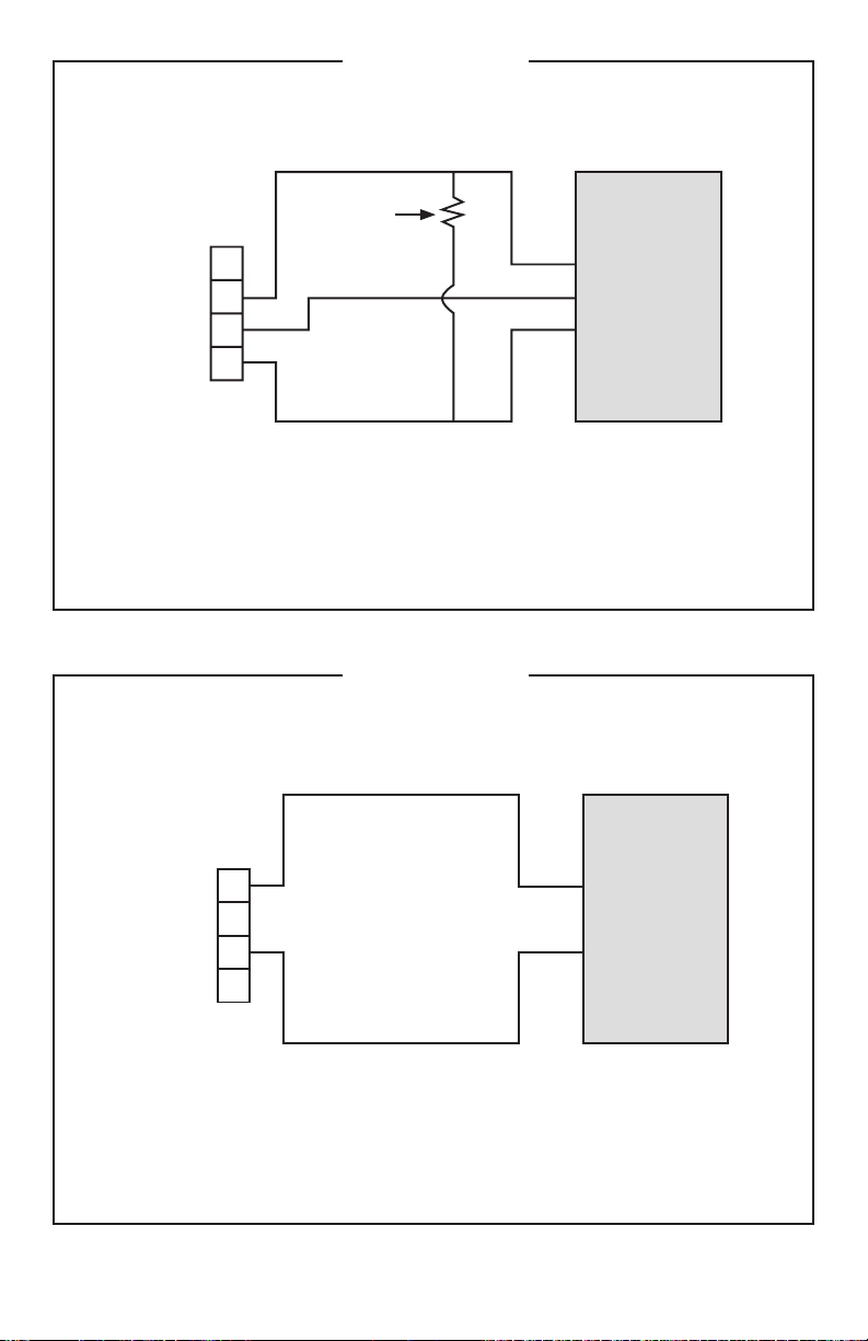
Wiring Diagram 1
+9 to 35 volt DC
Open Collector
Signal
3
2
1
4
Red
White
Black
Common
(Ground)
Terminal
Block
Customer
Interfacing
Equipment
The terminal block is identified as follows:
Pin #1 6 volt square wave (not used)
Pin #2 +9 to 35 volt DC Input
Pin #3 Common Ground
Pin #4 Open Collector signal Output
3
2
1
4
White
Black
Common
(Ground)
Terminal
Block
Customer
Interfacing
Equipment
6 volt Square
Wave Signal
The terminal block is identified as follows:
Pin #1 6 volt square wave
Pin #2 +9 to 35 volt DC Input (not used)
Pin #3 Common Ground
Pin #4 Open Collector signal Output (not used)
OPEN COLLECTOR SIGNAL OUTPUT
Resistor
(820 ohm min.)
Wiring Diagram 2
2
SQUARE WAVE OUTPUT
Page 5

3. Install the batteries. Make sure the positive
post is in the correct position.
4. Position the module on the turbine housing.
To avoid moisture damage, make sure the
seal is fully seated. Tighten the four screws
on the front of the module.
Ten feet (3m) of cable is provided with the
module. Trim the cable to desired length or
extend it as necessary.
Verify Meter Accuracy
Before using, check the meter’s accuracy and
verify calibration.
1. Make sure there is no air in the system by
starting the flow until it runs steadily. Then,
stop the flow using a valve or nozzle.
2. Hold down DISPLAY for 3 seconds to zero
the meter’s Batch Total. When zeros appear,
release the button.
3. Meter an exact known volume into an
accurate container. For best results, meter
with one continuous full stream.
4. Check the volume against the display
or recording equipment. If the amount
metered is accurate, field calibration is not
necessary. If not, refer to the Calibration
Section for further instructions.
OPERATION
Batch and Cumulative Totals
The display maintains two totals. The Cumulative Total provides continuous measurement
and cannot be manually reset. The Batch Total
can be reset to measure flow during a single
use. The Cumulative Total is labeled with TOTAL
1 LOCKED indicating that this total is locked
and cannot be manually zeroed. Batch Total is
labeled with TOTAL 2.
When the Cumulative Total reaches a maximum
reading of 999,999, it will automatically reset
to zero.
Press the DISPLAY button briefly to switch
between the batch, cumulative total, and
flowrate.
NOTE: Totalization counts total units without
differentiating between gallons, liters or
field calibrated units.
Flowrate Feature
When this feature is activated, the word FLOWRATE displays to the left on the bottom line.
When FLOWRATE is displayed, the numbers
on the middle line reflect the rate of flow, for
example, the current gallons per minute (GPM)
or liters per minute (LPM).
Display FLOWRATE
To use this feature, press and release DISPLAY
until FLOWRATE appears to the left of the
bottom line.
Activate the Meter
Turn the meter ON by starting water flow or
briefly pressing the DISPLAY button. The meter
will display the Batch or Cumulative Total from
last use.
Press DISPLAY briefly to display the Batch
Total. Hold the DISPLAY button down for 3
seconds to reset the Batch Total to zero.
The meter is programmed to turn off automatically if not used for 4 minutes.
Factory and Field Calibration Curves
All calibration information is visible to the user
as words in the upper part of the display, above
the numeric digits.
All units are configured with a “factory”
calibration curve. Both gallons and liters are
available (“GAL” or “LTR” will be displayed). Use
the CALIBRATE and DISPLAY buttons to switch
between gallons and liters. This curve is NOT
user adjustable: the word “PRESET” is
displayed to show this. (The factory calibration is
stored permanently in the computer’s memory.)
The “field” calibration curve may be set by the
user, and can be changed or modified at any
time using the calibration procedure described
below in the Calibration Section. Totals or
flowrate derived from the field calibration are
visible when the field calibration setting is selected
(“CAL B” will be visible on the top line).
3
Page 6

Selecting a Different
Calibration Setting
You can switch between GAL and LTR modes
at will without “corrupting” totalizer contents.
For example, the computer can totalize 10.00
gallons. If the user switches to LTR mode, the
display will immediately change to “37.85” (the
same amount in units of liters). GAL / LTR
switching also works in FLOWRATE mode.
To select a different calibration setting, first press
and hold the CALIBRATE button. Continue to
hold it while also pressing and releasing the
DISPLAY button. (You may then also release
the CALIBRATE button.) The flag indicators
in the top line of the display will change to
show the newly selected calibration setting.
Calibration settings change in this order:
GAL, LTR, CAL B, GAL, etc. While fluid is
flowing, only the GAL and LTR selections may
be made. However, when NO fluid flow is
occurring, any setting may be selected.
Field Calibration
Factory calibration settings are customprogrammed into each flowmeter during
production, using water at 70°F (21°C). Readings
using the standard factory calibration curves
may not be accurate in some situations
– for example, under extreme temperature
conditions. You can field calibrate the meter
if you are using fluids other than water.
For improved accuracy under such conditions,
the OMEGA flow computer allows for “field”
calibration, that is, user entry of custom calibration parameters. A “single point” calibration
may yield acceptable accuracy in the middle of
the flow range, but 5 or more calibration points
may yield a higher level of accuracy, especially
at the lower end of the flow range. Up to 15
custom calibration points can be entered.
The use of a uniformly dependable, accurate
calibration container is highly recommended
for the most accurate results. Due to high
flowrate, it is strongly recommended that Field
Calibration be completed with a combination of
volume and weight using fine resolution scales.
Before Beginning Field Calibration
For the most accurate results, dispense at a
flowrate which best simulates your actual operating conditions. Avoid “dribbling” more fluid or
repeatedly starting and stopping the flow –
these actions will result in less accurate calibrations.
Make sure you meet the meter’s minimum
flowrate requirements:
FTB690 Series Meters
1/2 inch meter 1 GPM (3.8 LPM)
3/4 inch meter 2 GPM (7.5 LPM)
1 inch meter 5 GPM (18.8 LPM)
1-1/2 inch meter 10 GPM (37.85 LPM)
2 inch meter 20 GPM (75 LPM)
For best results, the meter should be installed
and purged of air before field calibration.
Dispense/ Display Field
Calibration Procedures
1. Hold down CALIBRATE while pressing and
releasing DISPLAY until the field calibration
curve appears (“CAL B” message will be
displayed). Release both buttons.
2. To calibrate, press and hold the CALIBRATE button. While continuing to
hold CALIBRATE, also press and hold the
DISPLAY button. Hold both buttons for about
3 seconds until you see a blinking “dd CAL”
message. Once the “dd CAL” message
appears, release both buttons. You are
now in field calibration mode.
3. Once the buttons have been released
from Step 2, the display will show the
blinking message “run 01”. If you want to
exit the calibration now before dispensing
any fluid, go to Step 11.
4. If you want to continue with the calibration,
but have not dispensed any fluid yet, make
your final preparations to your pumping
system, but don’t start pumping yet.
5. Start your pumping system so that fluid
flows through the meter. The display
will stop blinking and show the “run 01”
message. Dispense into a container that
allows you to judge the amount of fluid
pumped. When you have pumped the
desired amount (for example, 10 gallons),
stop the fluid flow quickly.
6. Once the flow has stopped, briefly press
and release both buttons. At this point the
computer display will change to “0000.00”
with the left-hand digit blinking.
4
Page 7

7. Enter the volume (amount) of fluid that you
dispensed (for example, if your 10-gallon
container is full, enter “10.0” for gallons or
“37.85” for liters). To enter numbers, use the
CALIBRATE button to change the value of
the digit that is blinking and use the DISPLAY
button to shift the “blink” to the next digit.
8. Once the correct number is entered, briefly
press and release both buttons. The
display will now change to a blinking “run 02”
message. You have installed the new cal-curve
point. You are ready to end calibration (Step
10) or enter another new calibration point
(Step 9).
9. To enter another calibration point, go back
and repeat Steps 3 through 8. It is possible
to set up to 15 cal-curve points, and the
“run ##” message will increment each time
you repeat the calibration process (run 01,
run 02, run 03, etc., up to run 15).
10. To end calibration, press and hold both
buttons for about 3 seconds until you see
the “CAL End” message. After you release
the buttons the computer will resume normal operations with the new cal point(s)
active.
11. If you HAVE NOT dispensed any fluid, you
can exit calibration without changing the
cal curve. If the message “run 01” is showing
and you have not dispensed any fluid,
hold both buttons for about 3 seconds until
you see a “CAL End” message. After you
release the buttons, the computer will
resume normal operation and the old curve
(if you entered one in the past) is still intact.
CAUTION
Blowing compressed air through the turbine
assembly could damage the rotor.
Battery Replacement
The meter is powered by two 3-volt lithium
batteries which may be replaced while the
meter is installed. When batteries are removed
or lose power, the batch and cumulative totals
reset to zero but the field and factory calibrations
are retained.
If the meter display becomes dim or blank,
replace the batteries as follows:
1. Remove the four Phillips-head screws from
the face of the meter and lift the faceplate
from the turbine.
2. Remove the old batteries and clean any
corrosion from the terminals.
3. Install new batteries. Make sure the positive
post is in the correct position.
4. When the batteries are replaced, the faceplate will power ON. Check the display to
ensure normal functions have resumed
before assembling again.
5. Reseat batteries, if necessary, and position
the faceplate on the turbine housing.
To avoid moisture damage, make sure the
seal is fully seated. Tighten the four screws
on the faceplate.
SPECIFICATIONS
MAINTENANCE
Proper handling and care will extend the life
and service of the meter.
Turbine Rotor
The meter is virtually maintenance-free.
However, it is important the rotor moves freely.
Keep the meter clean and free of contaminants.
If the rotor does not turn freely, apply a penetrating lubricant on the rotor, shaft, and bearings.
Remove any debris or deposits from the rotor
using a soft brush or small probe. Be careful not
to damage the turbine rotor or supports.
Inlet and Outlet:
For Soc Models:
FTB691/FTB691-P 1/2" Sch 40, Soc
FTB692/FTB692-P 3/4" Sch 40, Soc
FTB693/FTB693-P 1" Sch 40, Soc
FTB694/FTB694-P 1-1/2" Sch 40, Soc
FTB695/FTB695-P 2" Sch 40, Soc
For NPT Models:
FTB691-NPT/FTB691-NPT-P 1/2" NPT
FTB692-NPT/FTB692-NPT-P 3/4" NPT
FTB693-NPT/FTB693-NPT-P 1" NPT
FTB694-NPT/FTB694-NPT-P 1-1/2" NPT
FTB695-NPT/FTB695-NPT-P 2" NPT
Design Type: Turbine
5
Page 8

Wetted Components:
Housing: PVC
Journal Bearings: Ceramic
Shaft: Tungsten Carbide
Rotor and Supports: PVDF
Retaining Washer: Stainless Steel
Fitting Types: Slip - Schedule 40 Soc or NPT
Max. Working Pressure: 150 PSIG @ 73°F
U.S. Measurement
Unit of Measure: Gallon
Flow Range:
1/2 inch 1 - 10 GPM
3/4 inch 2 - 20 GPM
1 inch 5 - 50 GPM
1-1/2 inch 10 - 100 GPM
2 inch 20 - 200 GPM
Accuracy: ± 3.0% of reading (Accuracy can
be improved with field calibration)
Operating Temperature: +32° to +140° F
NOTE: Do not allow fluid to freeze inside
meter.
Storage Temperature: –40° to +158° F
Weight:
1/2 inch .31 lbs.
3/4 inch .38 lbs.
1 inch .51 lbs.
1-1/2 inch .81 lbs.
2 inch 1.14 lbs.
Dimensions - inches (W x H x L):
1/2 inch 2 x 2.5 x 4.3
3/4 inch 2 x 2.7 x 5.3
1 inch 2 x 3 x 6
1-1/2 inch 2.3 x 3.6 x 7
2 inch 2.8 x 4.1 x 7.5
Metric Measurement
Unit of Measure: Liter
Flow Range:
1/2 inch 3.8 - 38 LPM
3/4 inch 7.6 - 76 LPM
1 inch 19 - 190 LPM
1-1/2 inch 38 - 380 LPM
2 inch 76 - 760 LPM
Accuracy: ± 3.0% of reading (Accuracy can
be improved with field calibration)
Operating Temperature: 0° to +60° C
NOTE: Do not allow fluid to freeze inside
meter.
Storage Temperature: –40° to +70° C
Weight:
1/2 inch .141 kg
3/4 inch .173 kg
1 inch .232 kg
1-1/2 inch .368 kg
2 inch .518 kg
Dimensions - cm (W x H x L):
1/2 inch 5.1 x 6.4 x 10.9
3/4 inch 5.1 x 6.9 x 13.5
1 inch 5.1 x 7.6 x 15.2
1-1/2 inch 5.8 x 9.1 x 17.8
2 inch 7.1 x 10.4 x 19.1
PARTS
The following replacement parts and accessories are available for the FTB690 Series
meters:
Part No. Description
FLSC790-BATT Battery Replacement Kit
FTB890 O-ring O-Ring
FTB691-RK 1/2 inch, Soc Turbine
Assembly Kit
FTB691-NPT-RK 1/2 inch, NPT, PVC, Turbine
Assembly Kit
FTB692-RK 3/4 inch, Soc Turbine
Assembly Kit
FTB692-NPT-RK 3/4 inch, NPT, PVC Turbine
Assembly Kit
FTB693-RK 1 inch, Soc Turbine
Assembly Kit
FTB693-NPT-RK 1 inch, NPT, PVC Turbine
Assembly Kit
FTB694-RK 1-1/2 inch, Soc Turbine
Assembly Kit
FTB694-NPT-RK 1-1/2 inch, NPT, PVC,
Turbine Assembly Kit
FTB695-RK 2 inch, Soc Turbine
Assembly Kit
FTB695-NPT-RK 2 inch, NPT, PVC Turbine
Assembly Kit
Computer Kits:
FTB691-CK 1/2 inch, Computer Assy Kit
FTB692-CK 3/4 inch, Computer Assy Kit
FTB693-CK 1 inch, Computer Assy Kit
FTB694-CK 1-1/2 inch, Computer
Assy Kit
FTB695-CK 2 inch, Computer Assy Kit
6
Page 9

E S P A Ñ O L
AVISO IMPORTANTE
Utilizar los metros de los Series del FTB690
con agua y otros productos químicos que son
compatibles con les componentes que se exponen
al líquido (véase la sección de especificaciones). No utilizar para medir el incompatible
combustible o los productos químicos. Los
metros de la serie del FTB690 están disponibles
con una visualización electrónica local, o un
módulo de salida condicionado de la señal para
proporcionar una señal numérica al equipo de
interconexión del cliente. Los medidores Series
FTB690 miden en galones o litros. Referirse a la
sección de la calibración para mayores detalles.
Estos medidores no son legales para las
aplicaciones comerciales.
Los medidores de las Series FTB690 son muy
sensibles a interferencia electrónica si funcionan
a 1 o 2 pulgadas de algunos motores eléctricos
o de otras fuentes del uso electrónico.
Instalar su medidor en línea, u horizontalmente,
o verticalmente, o en el extremo de la manguera
adyacente al inyector. No se recomienda la
instalación a las conexiones de metal. Siga
estos pasos para instalar:
1. Planee instalar la turbina con una longitud
mínima de la pipa recta de esta manera:
– Contra la corriente de la turbina,
permita a una longitud mínima de la
– Con la corriente de la turbina, permita
una longitud mínima de la pipa recta de 5
veces el diámetro interno de la turbina.
2. Para Las Conexiones Del Soc utilizar
solamente los solventes aprobados para
pegar PVC.
Para Las Conexiones Del NPT cubrir las con
exiones de pipa con la vueltas de cinta del
3 a 4 veces. Cerciorarse de que la cinta no
imponga en la trayectoria del flujo.
3. Unir el metro con la flecha señalada en la
dirección del flujo.
INSTALACIÓN
pipa recta de 10 veces el diámetro
interno de la turbina.
4. Para Las Conexiones Del NPT utilizar
solamente sus manos para apretar las
conexiones del metro. No utilizar una llave
inglesa o una herramienta similar para
apretar. Esto puede dañar la cubierta.
Señal de Salida Condicionada
Cableado De Módulo
Este módulo de Señal de salida condicionada
se puede conectar para proporcionar una
salida de colector abierta o de señal de onda
cuadra-da de 6-voltios.
Al instalar un flujómetro de la turbina de la
serie del FTB690-P, el factor K correcto se
debe incorporar en el dispositivo de la lectura.
Usted puede encontrar el factor K impreso en
el cuerpo de la turbina. Todos los factores K en
flujómetros del Omega se calculan en pulsos
por galón (PPG).
Señal de Salida De Colector Abierto
Para alcanzar una señal de salida de colector
abierto, refierase por favor al digrama eléctrico
1. El bloque de terminales está situado en
el lado trasero del módulo. El módulo viene
montado de fábrica para señal de colector
abierta. Por favor proporcionar (el resistor de
un minimo de 820 ohmios), si no es provisto
por el equipo de recepción.
Diez pies (3m) de cable se proporcionan con el
módulo. Ajustar el cable a la longitud deseada
o extender el cable cuanto le sea necesario.
Se puede alcanzar una señal de salida de
colector abierto hasta distancias de 5.000
pies (1,524m).
Salida de corrente de
Onda Cuadrada
Para lograr una salida de corriente de onda
cuadrada, refierase por favor al digrama eléctrico 2 y utilize un kit electrónico de bateria del
medidor digital (vendido por separado) para la
fuente de energia de la bateria. El bloque de
terminales y la localización de la bateria están
situados en el lado trasero del modulo. Acceda
al módulo de la siguiente manera:
1. Quitar los cuatro tornillos de cabeza
Phillips del frente del módulo. Levantar el
módulo de la turbina.
7
Page 10

2. Para cambiar las conexiones del bloque
de terminales, aflojar los tornillos apropiados. Volver a conectar los alambres
en las posiciones apropiadas y apretar
los tornillos.
3. Instalar las baterias. Cerciorarse de que el
poste positivo esté en la posición correcta.
4. Colocar el módulo en la cubierta de la
turbina. Para evitar daños causados por
la humedad, cerciorarse de que el anillo
esté asentado completamente. Apretar los
cuatro tornillos en el frente del módulo.
Diez pies (3m) de cable se proporcionan con el
módulo. Ajustar el cable a la longitud deseada o
extender el cable cuanto le sea necesario.
Verificar La Exactitud Del Metro
Antes de usar, comprobar la exactitud del metro
y verificar la calibración.
1. Cerciorarse de que no haya aire en el sistema
comenzando el flujo hasta que funciona
constantemente. Entonces, detenga el flujo
usando una válvula o un inyector.
2. Mantenga el botón de la EXHIBICIÓN
durante 3 segundos para llevar a cero el
total de medidor. Cuando aparezcan los
ceros, suelte el botón.
3. Con el medidor, mida un volumen exacto
en un envase exacto. Para mejores resul tados, medir con una corriente complete y
continua.
4. Comprobar el volumen contra la pantalla o
el equipo de grabacion. Si la cantidad medi-
da es exacta, la calibración de campo no
es necesaria. Si no, refeierase a la sección
de la calibración.
OPERACIÓN
Hornada y Totales Acumulativos
La pantalla mantiene dos totales. El total
acumulativo proporciona la medida continua y
no puede ser reajustado manualmente. El total
de hornada se puede reajustar para medir el flujo
durante una sola vez . El total acumulativo se
etiqueta con el TOTAL 1 LOCKED. Esto indica
que el total esta bloqueado y no puede ser
puesto a cero manualmente. El total de hornada
se etiqueta con el TOTAL 2.
Cuando el total acumulativo alcanza una lectura máxima de 999.999, se reajustará automáticamente a cero.
Presionar el botón de DISPLAY brevemente
para cambiar entre la hornada, el total acumulativo, y el índice de flujo.
NOTA: Totalization cuenta las unidades totales
sin distinguir entre los galones, los litros
o las unidades calibradas de campo.
Característica Del Índice De Flujo
Cuando se activa esta característica, aparece
la palabra FLOWRATE a la izquierda hasta
abajo.
Cuando se exhibe el FLOWRATE, los números
en la línea media reflejan el régimen, por
ejemplo, los galones actuales por minuto (GPM)
o los litros por minuto (LPM).
Exhibición Del Índice De Flujo
Para utilizar esta característica, presionar y
soltar el botón del DISPLAY hasta que
FLOWRATE aparece a la izquierda hasta abajo.
Activar El Metro
Encienda el metro comenzando el flujo del agua
o brevemente presionando el botón del
DISPLAY. El medidor exhibirá la hornada o el
total acumulativo a partir de la última vez que
fue utilizado.
Presionar el botón del DISPLAY brevemente
para exhibir el total de hornada. Oprima el
botón de DISPLAY por 3 segundos para
reajustar el total de hornada a cero.
El medidor se apaga automáticamente si no
es usado durante 4 minutos.
Curvas De Calibración De La
Fábrica y Del Campo
Toda la información de la calibración es visible
al usuario como palabras en la parte superior
de la exhibición, sobre los dígitos numéricos.
Todas las unidades se configuran con una
curva de calibración de la “fábrica”. Los galones
y los litros están disponibles. (el “GAL” o
el “LTR” será visible). Utilizar los botones del
CALIBRATE y del DISPLAY para cambiar entre
los galones y los litros. Esta curva de calibración
8
Page 11

no es ajustable por el usuario. La palabra PRESET
se exhibe para demostrar esto. (La calibración
de la fábrica se almacena permanentemente en
la memoria de computadora.)
La curva de calibración de “campo” se puede
fijar por el usuario. La calibración se puede
cambiar o modificar en cualquier momento
usando los procedimientos de la calibración
descritos en la sección de la calibración. Los
totales o el índice de flujo derivados de la
calibración de campo son visibles cuando se
selecciona el ajuste de la calibración de campo
(la “CAL B” será visible en la línea superior).
Seleccionar Un Ajuste
Diverso De La Calibración
Usted puede cambiar entre los modos del GAL
y del LTR a voluntad sin afectar los totales. Por
ejemplo, la computadora puede sumar 10,00
galones. Si el usuario cambia al modo del LTR,
la exhibición cambiará inmediatamente a
“37,85” (la misma cantidad en las unidades de
los litros). La conmutación del GAL/LTR
también trabaja en el modo del FLOWRATE.
Para seleccionar un ajuste diverso de la calibración, oprima y sostenga el botón de la
CALIBRATE. Continuar sosteniendo el botón
mientras que también presiona y suelta el botón
de DISPLAY. (usted puede entonces también
soltar el botón de la CALIBRATE.) Los indicadores de la bandera de la línea superior de
la exhibición cambiarán para demostrar el
nuevo ajuste seleccionado de la calibración.
Los ajustes de la calibración se cambian en este
orden: GAL, LTR, CAL B, GAL, etc. Mientras que
está fluyendo el líquido, sólo las selecciones
del galón y del litro pueden ser hechas. Sin
embargo, cuando no está fluyendo NINGÚN
líquido, cualquier selección puede ser hecha.
Calibración Del Campo
Los ajustes de la calibración de la fábrica
se programan especificamente en cada
flujómedidor durante su producción usando
agua a 70°F (21°C). Las lecturas que utilizan las
curvas de calibración estándares de la fábrica
pueden no ser exactas en algunas situaciones.
Por ejemplo, cuando se encuentran bajo
condiciones de temperatura extremas. Usted
puede campo calibrar el metro si usted está
utilizando los líquidos con excepción del agua.
Para la exactitud mejorada bajo tales condiciones, la computadora OMEGA de flujo tienen
en cuenta la calibración del “campo” (es decir
un apunte del usuario dentro de los parámetros
de calibración especiales). La calibración de
“un solo punto” puede rendir una exactitud
aceptable en medio de la gama del flujo. Cinco
o más puntos de calibración pueden rendir un
nivel más alto de exactitud, especialmente en
el extremo inferior de la gama del flujo. Hasta
15 puntos de calibración especiales pueden ser
incorporados.
Se recomienda altamente usar un envase
confiable, y exacto para la calibración. Para
obtener resultados más exactos. debido al alto
índice de flujo, se recomienda fuertemente que
la calibración de campo esté determinada con
una combinación del volumen y del peso
usando las escalas de alta resolución.
Antes De Comenzar La
Calibración De Campo
Para resultados más exactos, dispense un
índice de flujo que simule lo mejor posible sus
condiciones de funcionamiento reales. Evite
“de gotear” más líquido o en varias ocasiones,
o el comenzar y de parar el flujo. Estas acciones
darán lcomo resultado calibraciones menos
exactas.
Cerciorese de reunir todos los requisitos mínimos del índice de flujo del medidor:
Medidores de las Series del FTB690
Medidor de 1/2 pulgada de
1 GPM (3,8 LPM)
Medidor de 3/4 pulgada de
2 GPM (7,5 LPM)
Medidor de 1 pulgada de
5 GPM (18,8 LPM)
Medidor de 1-1/2 pulgadas de
10 GPM (37,85 LPM)
Medidor de 2 pulgadas de
20 GPM (75 LPM)
Para mejores resultados, el medidor se debe
instalar y purgar del aire antes de la calibración
de campo.
9
Page 12

Procedimientos De la Calibración
De Campo De Dispense/Display
1. Mantener oprimido el botón del CALIBRATE
mi entras que presionar y suel ta el
boton DISPLAY hasta que aparece la
curva de calibración de campo (mensaje
de “CAL B” será exhibido). Suelte ambos
botones.
2. Para calibrar, presionar y sostener el botón
del CALIBRATE. Mientras que continúa
oprimiendo el CALIBRATE, también
presionar y sostener el botón del DISPLAY.
Sostener ambos botones por cerca de 3
segundos hasta que usted vea el mensaje
de “dd-CAL” en centelleo. Una vez que
mensaje del “dd-CAL”, aparezca, suelte
ambos botones. Usted ahora está en el
modo de la calibración de campo.
3. Una vez que los botones se hayan soltado
(el paso 2), la exhibición demostrará el
mensaje del centelleo “RUN 01”. Si usted
desea salir del proceso de la calibración
antes de dispensar cualquier líquido, ir al
paso 11.
4. Si usted desea continuar con la calibración, pero no ha dispensado ningún
líquido todavía, hacer las preparaciones
finales a su sistema de bombeo, pero no
comenzar a bombear todavía
5. Comience su sistema de bombeo de
modo que el líquido atraviese el metro.
La exhibición parará el centelleo y demo
strará el mensaje del “ RUN 01”. Dispense
el líquido en un envase que permita
que usted juzgue la cantidad de líquido
bombeada. Cuando usted ha bombeado
la cantidad deseada (por ejemplo, 10
galones), detenga el flujo fdel liquido
inmediatamente.
6. El flujo ha parado; brevemente presione y
suelte una vez ambos botones. En este
momento la exhibición de la computadora
cambiará al “0000.00” con el centelleo a
la izquierda del dígito.
7. Introduzca el volumen (cantidad) de
líquido que usted ha dispensado (por
ejemplo, si su envase de los 10-gallon es
lleno, introducir “10,0” para los galones o
“37,85” para los litros). Para incorporar los
números, utilizar el botón del CALIBRATE
para cambiar el valor del dígito que está
en centelleo. Utilizar el botón del DISPLAY
para cambiar de puesto el “centelleo” al
dígito siguiente.
8. Una vez que se incorpore el número
correcto, presionar y soltar brevemente
ambos botones. La exhibición ahora
cambiará a un mensaje “RUN 02” en
centelleo. Usted ahora ha instalado el nuevo
punto de la cal-curva. Usted esta listo para
terminar la calibración (paso 10) o incorporar
otro nuevo punto de calibración (paso 9).
9. Para incorporar otro punto de calibración,
vuelva a repetir los pasos del 3 al 8. Es
posible fijar hasta 15 puntos de la cal-
curva, y “run ##” del funcionamiento
incrementará cada vez que usted repite
el proceso de la calibración (run 01, run
02, run 03, etc., hasta el run 15).
10. Para terminar el proceso de la calibración,
presionar y sostener ambos botones por
cerca de 3 segundos hasta que usted vea
el mensaje del “CAL End”. Después de
que usted suelte los botones, la compu-
tadora reasumirá las operaciones normales con el nuevo punto(s) activos
calibrados.
11. Si usted no ha dispensado ningún líquido,
usted puede salir de la calibración sin
cambiar la curva. Si el mensaje “run 01”
está mostrando y usted no ha dispensado
ningún líquido, sostenga ambos botones
por cerca de 3 segundos hasta que usted
vea el mensaje en un extremo del “CAL
End”. Después de soltar los botones,
la computadora reasumirá la operación
normal y la vieja curva (si usted introdujo
una en el pasado) sigue intacta.
La utilización y el cuidado apropiados ampliarán
la vida y el servicio del medidor.
MANTENIMIENTO
Rotor De Turbina
El medidor practicamente no tiene necesidad
de mantenimiento. Sin embargo, es importante
que los movimientos del rotor ocurran libremente. Mantener el medidor limpio y libre de
contaminantes.
10
Page 13

Si el rotor no da vuelta libremente, aplicar
un lubricante penetrante en el rotor, el eje, y
los rodamientos. Quitar cualquier desecho o
depósito del rotor usando un cepillo suave o una
punta de prueba pequeña. Tenga cuidado de
no dañar el rotor de turbina o los soportes.
PRECAUCIÓN
El aire comprimido a través del montaje de
la turbina podría dañar el rotor.
Reemplazo De La Batería
El medidor funciona a través de dos baterías del
litio 3-voltios que puedan ser substituidas
mientras que el metdidor está instalado.
Cuando las baterías se quitan o pierden la
potencia, la hornada y los totales acumulativos
seran reajustados a cero, pero las calibraciones
de campo y de la fábrica se conservan.
Si la exhibición del metro llega a estar dévil o en
blanco, substituir las baterías de esta manera:
1. Quitar los cuatro tornillos de la cara del
metro y levantar la placa frontal de la
turbina.
2. Quitar las viejas baterías y limpiar cualquier
corrosión de los terminales.
3. Instalar las baterías nuevas. Cerciorarse de
que el poste positivo esté en la posición
correcta.
4. Cuando se substituyen las baterías, la
placa frontal estará encendida. Comprobar
la exhibición para asegurarse de que las
funciones normales han resumido antes
de montar otra vez.
5. Volver a sentar las baterías, en caso
necesario, colocar la placa frontal en la
cubierta de la turbina. Evite el daño
causado por la humedad, cerciorarse de
que el anillo esté asentado completamente.
Apretar los cuatro tornillos en la placa
frontal.
ESPECIFICACIONES
Entrada y Enchufe:
Por Soc Modelos:
FTB691/FTB691-P 1/2" de 40, Soc
FTB692/FTB692-P 3/4" de 40, Soc
FTB693/FTB693-P 1" de 40, Soc
FTB694/FTB694-P 1-1/2" de 40, Soc
FTB695/FTB695-P 2" de 40, Soc
Por NPT Modelos:
FTB691-NPT/FTB691-NPT-P 1/2" de NPT
FTB692-NPT/FTB692-NPT-P 3/4" de NPT
FTB693-NPT/FTB693-NPT-P 1" de NPT
FTB694-NPT/FTB694-NPT-P 1-1/2" de NPT
FTB695-NPT/FTB695-NPT-P 2" de NPT
Tipo Del Diseño: Turbina
Componentes Mojados:
Cubierta: PVC
Rodamientos: De Cerámica
Eje: Carburo De Tungsteno
Rotory Soportes: PVDF
Arandela De Retención: Stainless Steel
Tipo De Las Guarnicione: Resbalón de 40 Soc o NPT
Máxima Presión De Funcionamiento:
150 PSIG a los 73°F
Medida De Estados Unidos
Unidad De La Medida: Galón
Gama Del Flujo:
1/2" 1 - 10 GPM
3/4" 2 - 20 GPM
1" 5 - 50 GPM
1-1/2" 10 - 100 GPM
2" 20 - 200 GPM
Exactitud: ±3.0% de la lectura (la exactitud se
puede mejorar con la calibración del
campo)
Temperatura De Funcionamiento:
+32° a +140° F
NOTA: No permitir que el líquido
congele dentro del metro.
Temperatura Del Almacenaje:
-40° a +158° F
Peso:
1/2" .31 libras
3/4" .38 libras
1" .51 libras
1-1/2" .81 libras
2" 1,14 libras
11
Page 14

Dimensiones - Pulgadas
(Grosor x Altura x Longitud):
1/2" 2 x 2,5 x 4,3
3/4" 2 x 2,7 x 5,3
1" 2 x 3 x 6
1-1/2" 2,3 x 3,6 x 7
2" 2,8 x 4,1 x 7,5
Medida Métrica
Unidad De La Medida: Litro
Gama Del Flujo:
1/2" 3,8 - 38 LPM
3/4" 7,6 - 76 LPM
1" 19 - 190 LPM
1-1/2" 38 - 380 LPM
2" 76 - 760 LPM
Exactitud: ±3.0% de la lectura (la exactitud se
puede mejorar con la calibración del
campo)
Temperatura De Funcionamiento:
0° a +60° C
NOTA: No permitir que el líquido
congele dentro del metro.
Temperatura Del Almacenaje:
-40° a +70° C
Peso:
1/2" .141 kilogramo
3/4" .173 kilogramo
1" .232 kilogramo
1-1/2" .368 kilogramo
2" .518 kilogramo
Dimensiones - Centímetro
(Grosor x Altura x Longitud):
1/2" 5,1 x 6,4 x 10,9
3/4" 5,1 x 6,9 x 13,5
1" 5,1 x 7,6 x 15,2
1-1/2" 5,8 x 9,1 x 17,8
2" 7,1 x 10,4 x 19,1
PIEZAS
Las piezas y los accesorios siguientes de
recambio están disponibles para los medidores
de los Series del TM:
Parte No. Descripción
FLSC790-BATT Systema de reemplazo de
la batería
FTB890 O-Ring Anillo-O
FTB691-RK 1/2" - kit de la assamblea
de la turbina
FTB691-NPT-RK 1/2" NPT, PVC - kit de la
assamblea de la turbina
FTB692-RK 3/4" - kit de la assamblea
de la turbina
FTB692-NPT-RK 3/4" NPT, PVC - kit de la
assamblea de la turbina
FTB693-RK 1" - kit de la assamblea de
la turbina
FTB693-NPT-RK 1" NPT, PVC - kit de la
assamblea de la turbina
FTB694-RK 1-1/2" kit de la assamblea
de la turbina
FTB694-NPT-RK 1-1/2" NPT, PVC - kit de la
assamblea de la turbina
FTB695-RK 2" - kit de la assamblea de
la turbina
FTB695-NPT-RK 2" NPT, PVC - kit de la
assamblea de la turbina
Kits De la Computadora:
FTB691-CK 1/2" - kit de la asamblea
de la computadora
FTB692-CK 3/4" - kit de la asamblea
de la computadora
FTB693-CK 1" - kit de la asamblea de
la computadora
FTB694-CK 1-1/2" - kit de la asamblea
de la computadora
FTB695-CK 2" - kit de la asamblea de
la computadora
12
Page 15

D E U T S C H
WICHTIGE NACHRICHT
Die FTB690 Series Meßinstrumente mit
Wasser und anderen Chemikalien benutzen,
die mit Bestandteilen kompatibel sind, die
Flüssigkeit (Spezifikationen Abschnitt sehen).
Verwenden Sie nicht zu Meter von Kraftstoff
ofer chemikalien unvereinbar. Die FTB690 Reihe
Meßinstruments sind vorhanden entweder mit
einer lokalen elektronischen Anzeige oder einer
konditionierten Signalausgabebaugruppe, ein
digitales Signal zum Kunde Schnittstellenmodul
zur Verfügung zu stellen. FTB690 Series mißt
in Gallonen oder Litern. Auf den Kalibrierungsabschnitt für Details beziehen.
Diese Meßinstrumente sind nicht für den
Handel zulässig.
FTB690 Series Meßinstrumente sind gegen
elektronische Störung sehr empfindlich, wenn
sie innerhalb 2,5 bis 5 cm einiger Elektromotoren oder anderer Quellen des elektronischen Gebrauches bedient werden.
INSTALLATION
Ihr Meßinstrument inline entweder am Ende des
Schlauches neben der Düse horizontal oder
vertikal anbringen. Installation zu Metallanschlüssen wird nicht empfohlen. Diesen
Schritten folgen, um anzubringen:
1. Planen, die Turbine mit einer minimalen
Länge geraden Rohres anzubringen:
– Gegen den Strom von der Turbine, einer
minimalen Länge des geraden Rohres
von 10mal dem internen Durchmesser
der Turbine erlauben.
– Stromabwärts von der Turbine, eine
minimale Länge des geraden Rohres
von 5mal dem inneren Durchmesser
der Turbine erlauben.
2. Für Soc Befestigungen nur Spachtelmasse
und Lösungsmittel verwenden, die zum
Kleben von PVC erlaubt sind.
Für NPT Befestigungen spule Klebeband
3 bis 4 mal um die Pipe-Verbindungen.
Sicherstellen, daß das Klebeband nicht das
Innere des Rohres berührt.
3. Das Meßinstrument mit dem Pfeil anbringen,
der in die Richtung des Flusses zeigt.
4. Für NPT Befestigungen nur Ihre Hände
benutzen um die Pipe-Verbindun. Wenn Sie
die Anschlüsse festziehen, sich erinnern,
keine Werkzeuge zu benutzen.
Konditioniertes Signal Ausgeben
Baugruppenverdrahtung
Diese konditionierte Signalausgabebaugruppe
kann verdrahtet werden, um einen geöffneten
Kollektorsignal-Ausgang oder Welle des Quadrats 6-volt Ausgang zur Verfügung zu stellen.
Wenn man ein FTB690-P Reihe Turbineströmungsmesser anbringt, muß der korrekte KFaktor in die Auslesenvorrichtung eingetragen
werden. Sie Können den K-Faktor finden
gedruckt auf dem Turbinekörper. Alle K-Faktoren
auf Omega Strömungsmessern werden in den
impulsen pro Gallone (PPG).
Öffnen Kollektor-Signal-Ausgang
Um einen geöffneten Kollektor Ausgang zu
erzielen, Bezugsbauschaltplan 1 signalisieren.
Der Klemmenblock ist auf der Rückseite des
Moduls. Das Modul ist die Fabrik, die für geöffneten Kollektorsignalausgang. Zusam-mengebaut wird Den (820-Ohm-Minimum) Widerstand
bitte zur Verfügung stellen, wenn er nicht durch
die empfangende Ausrüstung.
10 Fuß (3m) Kabel wird mit dem Modul.
Versehen Das Kabel zur gewünschten Länge
trimmen oder das Kabel wie benötigt verlängern. Abstände bis 5.000 Fuß (1,524m) könne
für geöffneten Kollektorsignalausgang erzielt
werden.
Quadratischer Welle Ausgang
Um Quadratischen Welle Ausgang zu erzielen,
Bezugsbauschaltplan 2 signalisieren und einen
elektronischen Digital Meßinstrument-Batterie-Installationssatz (separat verkauft) für die
Batterieleistung benutzen. Der Klemmenblock
und die Batterieposition sind auf der Rückseite
des Moduls. Zugang wie folgt:
1. Die vier Kreuzkopfschrauven von der Frontseite des Moduls entfernen. Das Modul von
der Turbine anheben.
13
Page 16

2. Um die Klemmenblockanschlüsse zu
ändern, die passenden Schrauben lösen.
Die Leitungen in den korrekten Positionen
wieder anschließen und die Schrauben
festziehen.
3. Die Batterien anbringen. Sicherstellen,
daß der positive Pfosten in der richtigen
Position ist.
4. Das Modul auf das Turbinegehäuse in Position bringen. Um Feuchtigkeit Beschädigung zu vermeiden, sicherstellen daß der
Dichtung völlig setzt. Die vier Schrauben
an der Frontseite des Moduls festziehen.
10 Fuß (3m) Kabel wird mit dem Modul versehen. Das Kabel zur gewünschten Länge trimmen
oder das Kabel wie benötigt verlängern.
MeßinstrumentGenauigkeit
Überprüfen
Bevor Sie verwenden, die Genauigkeit des
Meßinstruments überprüfen und die Kalibrierung überprüfen.
1. Überprüfen, daß es keine Luft in der Anlage
gibt, indem Sie den Fluß beginnen, bis er
ständig läuft. Dann den Fluß mit einem
Ventil oder einer Düse stoppen.
2. Die DISPLAY(ANZEIGEN) Taste 3 Sekunden lang niederhalten, um en Meter auf Null
zurückzustellen. Wenn null erscheint, die
Taste freigeben.
3. Das Meßinstrument ein genau bekanntes
Volumen in einen genauen Behälter abgeben lassen. Für beste Resultate mit einem
ununterbrochenen vollen Strom messen.
4 Das Vojumen gegan die Anzeige order
die Aufnahmeausrüstung überprüfen.
Wenn die Menge, die gemessen wird,
genau ist, ist Nacheichung nicht notwendig.
Wenn nicht, auf den Kalibrierungsabschnitt
für weitere Anweisungen beziehen.
BETRIEB
Reihe und kumulative
Gesamtmengen
Die Anzeige behält zwei Gesamtmengen. Die
kumulative Gesamtmenge liefert ununterbrochenes Maß und kann nicht manuell
zurückgestellt werden. Die Zwischensumme
kann zurückgestellt werden, um den Fluß
während eines einzelnen Gebrauches zu
messen. Die kumulative Gesamtmenge wird mit
TOTAL 1 LOCKED beschriftet. Dieses zeigt an,
daß die Gesamtmenge verschlossen ist und
nicht manuell auf Null eingestellt werden kann.
Zwischensumme wird mit TOTAL 2 beschriftet.
Wenn die kumulative Gesamtmenge eine
maximale Anzeige von 999.999 erreicht, stellt
sich sie automatisch bis null zurück.
Die DISPLAY (Anzeigen)-Taste kurz betätigen,
um zwischen Reihe, kumulative Gesamtmenge
und Fließgeschwindigkeit zu schalten.
ANMERKUNG: Totalization zählt die Gesamt-
maßeinheiten, ohne zwischen Gallonen,
Litern oder nachgeeichten Maßeinheiten
zu unterscheiden.
FließgeschwindigkeitEigenschaft
Wenn diese Vorichtung betätigt wird, erscheint
das Wort FLOWRATE Links auf der untersten
linie.
Wenn FLOWRATE Angezeigt wird, reflektieren
die Zahlen auf der mittleren Linie die Durchflußgeschwindigkeit, z.B., die gegenwärtigen
Gallonen pro Minute (GPM) oder Liter pro
Minute (LPM).
Fließgeschwindigkeits Anzeige
Um diese Eigenschaft zu benutzen, die
DISPLAY-Taste betätigen und freigeben,
bis FLOWRATE Auf der linken Seite des
Endergebnisses erscheint.
Das Meßinstrument betätigen
Das Meßinstrument einschalten, indem Sie den
Wasserfluß beginnen oder indem Sie kurz die
DISPLAY-Taste betätigen. Das Meßinstrument
zeigt die Zwischenmenge oder die kumulative
Gesamtmenge vom letzten Mal an, das sie
verwendet wurde.
Die DISPLAY-Taste kurz betätigen, um die
Zwischensumme anzuzeigen. Die DISPLAYTaste 3 Sekunden lang niederhalten, um die
Zwischensumme auf Null zurückzustellen.
Das Meßinstrument ist so programmiert, das
es sich automatisch abschaltet, wenn es 4
Minuten lang nicht in Betrieb ist.
14
Page 17

Fabrik- und Nacheichungskurven
Alle Kalibrierungsinformationen sind als
Wörter im oberen Teil der Anzeige, über den
numerischen Stellen sichtbar.
Alle Maßeinheiten werden mit einer “Fabrik”
Eichkurve hergestellt. Sie können entweder
Gallonen oder Liter wählen (“GAL” oder “LTR”
sind sichtbar). Die CALIBRATE und DISPLAY
Tasten benutzen, um zwischen Gallonen und
Liter zu schalten. Diese Eich-kurve ist NICHT
vom Benutzer verstellbar. Das Wort PRESET Wird
angezeigt, um dieses zu zeigen. (die Fabrikkalibrierung wird dauerhaft im Computerspeicher
gespeichert.)
Die “Nacheichungskurve” kann vom Benutzer
eingestellt werden. Die Kalibrierung kann
jederzeit mit den Kalibrierungsverfahren, die im
Kalibrierungsabschnitt beschrieben sind,
geändert oder umgesteuert werden. Gesamtmengen oder Fließgeschwindigkeiten, die auf
Nacheichung beruhen, werden sichtbar, wenn
die Nacheichungseinstellung vorgewählt wird
(“CAL B” ist auf der oberen Linie sichtbar).
Eine andere Kalibrierungseinstellung vorwählen
Sie können mit Leichtigkeit von GAL zum LTR
Modus wechseln, ohne die Gesamtmengen
zu verderben. Z.B. kann der Computer 10,00
Gallonen zusammenzählen. Wenn der Benutzer
zum LTR-Modus schälter, auf ändert die Anzeige
sofort “37,85” (die gleiche Menge in den
Maßeinheiten von Litern). GAL/LTR-Schaltung
arbeitet auch im FLOWRATE-Modus.
Um eine andere Kalibrierungseinstellung zu
wählen, zuerst die CALIBRATE Taste drücken
und halten. Weiterhin halten, Uahrend Sie die
DISPLAY Taste ebenfalls pressen und freigeben. (Sie können die KALIBRIEREN-TASTE
dann auch freigeben.) Die Markierungsfahnenanzeiger auf der obersten Linie ändern sich,
sodass sie die neugewählte Kalibrierung
anzeigen. Die Kalibrierungseinstellungen
ändern sich in dieser Reihenfolge: GAL, LTR,
CAL B, GAL, usw. Während die Flüssigkeit
fließt, können nur GAL oder LTR gewahlt
werden. Jedoch wenn KEINE Flüssigkeit fließt,
kann irgendeine Vorwähl betätigt werden.
Bereich-Kalibrierung
Die Fabrikkalibrierungseinstellung ist in jeden
Strömungsmesser zur Zeit der Herstellung
einprogrammiert worden, indem Wasser von
70°F (21°C) verwendet wurde. Anzeigen, die die
Standardfabrikeichkurven benutzen, können
möglicherweise nicht in einigen Situationen
genau sein, Z.B. unter extremen Temperaturbedingungen. Wenn Sie ander Flüssigkeiten
ausgenommen Wasser benutzen, können Sie
Bereich-Kalibrieren das Meßinstrument.
Für verbesserte Genauigkeit unter solchen
Bedingungen, erlaubt der Computer Nacheichung, d.h., kundenspezifischen Kalibrierungsparameter können eingegeben werden.
Kalibrierung auf eine “einzelnen Punk” kann
ak zeptable Genauigkeit in der Mitt der
Durchflußmenge ergeben, fünf oder mehr
Kalibrierstellen können ein höheres Niveau
der Genauigkeit, besonders am untereren
Ende der Durchflußmenge erbringen. Bis 15
kundenspezifische Kalibrierstellen können
eingetragen werden.
Für genaueste Resultate ist ein exakter, zuverlässiger Kalibrierungsbehälter unbedingt
empfehlenswert. Wegen der hohen Fließgeschwidigkeit, wird es stark empfohlen, daß
Nacheichung mit einer Kombination des
Volumens und des Gewichts mit Skalen der
feinen Trennung durchgeführt wird.
Vor Dem Beginn Der Nacheichung
Für die genauesten Resultate an einer Fließgesc h w i n digkeit zufüh ren, di e gut Ihre
tatsächlichen Betriebsbedingungen simuliert.
Vermeiden, mehr Flüssigkeit “zu tröpfeln”
oder wiederholt den Fluß zu beginnen und zu
stoppen. Diese Vorgänge ergeben weniger
genaue Kalibrierungen.
Versichern Sie sich, dass Sie die minimalen
Fließgeschwindigkeiten des Meßinstruments
erreichen:
FTB690 Series Meßinstrumente
1/2 Zoll 1 GPM (3,8 LPM)
3/4 Zoll 2 GPM (7,5 LPM)
1 Zoll 5 GPM (18,8 LPM)
1-1/2 Zoll 10 GPM (37,85 LPM)
2 Zoll 20 GPM (75 LPM)
Für beste Resultate soll das Meßgerät vor der
Nacheichung installiert werden und von Luft
befreit sein.
15
Page 18

Verfahren Der Dispense/Display
Nacheichung
1. Die CALIBRATE-Taste heruntergedrückt
halten während Sie DISPLAY betätigen und
freigeben, bis die Nacheichungs-kurve
erscheint (“CAL B” wird angezeigt). Beide
der Tasten freigeben.
2. Zum Kal ibri eren, die CAL IBRAT ETaste betätigen und halten. Fortfahren,
CALIBRATE Zu halten, die DISPLAY-Taste
auch betätigen und halten. Beide der
Tasten für ungefähr 3 Sekunden halten,
bis Sie die blinkende Anzeige “dd-CAL”
sehen. Sobald “dd-CAL” erscheint, beide
der Tasten freigeben. Sie sind jetzt im
Nacheichungsmodus.
3. Sobald die Tasten von Schritt 2 freigegeben
worden sind, erscheint die Blinkenanzeige
“run 01”. Wenn Sie den Kalibrierungsprozeß
jetzt be e nden möch t en, bevor S i e
irgendeine Flüssigkeit zuführen, zu Schritt
11 gehen.
4. Wenn Sie mit der Kalibrierung fortfahren
möchten, aber noch keine Flüssigkeit
zugeführt haben, die abschließenden
Vorbereitungen an Ihrem Pumpsystem
ausführen ohne mit pumpen anzufangen.
5. Ihr Pumpsystem anlassen, damit Flüssigkeit
das Meßinstrument durchfließt. Die Anzeige
stoppt zu blinken und zeigt die Anzeige
“run 01”. Flüssigkeit in einen Behälter
zuführen, der Ihnen erlaubt, die Menge
der Flüssigkeit zu beurteilen. Wenn Sie
die gewünschte Menge (zum Beispiel, 10
Gallonen) gepumpt haben, den Fluß schnell
stoppen.
6. Wenn die Flüßigkeit aufgehört hat, zu
fliessen, beide Tasten kurz betätigen und
freigeben. An diesem Punkt ändert sich die
Computeranzeige zum “0000.00” mit dem
linken Stellenblinken.
7. Das Volumen (Menge) der Flüssigkeit
eintragen, die Sie gepumpt haben (wenn Ihr
10-Gallonen-Behälter voll ist, “0,0” für
Gallonen oder “37,85” für Liter zum Beispiel
eintragen). Um die Zahlen einzutragen, die
CALIBRATE-Taste benutzen, um den
Wert der Stelle zu ändern, die blinkt.
Die DISPLAY-Taste benutzen, um das
“Blinzeln” auf die folgende Stelle zu
verschieben.
16
8. Sobald die korrekte Zahl eingetragen
ist, beide der Tasten kurz betätigen und
freigeben. Die Anzeige ändert sich jetzt zum
blinkenden “run 02”. Sie haben jetzt den
neuen Calkurvenpunkt angebracht. Sie sind
bereit, Kalibrierung (Schritt 10) zu beenden
oder eine andere neue Kalibrierstelle
(Schritt 9) einzutragen.
9 Um eine andere Kalibrierstelle einzutragen,
zurück gehen und Schritte 3 bis 8 wiederholen.
Es ist möglich, bis 15 Calkurvenpunkte
einzustellen, und die “run ##” erhöht sich jede
Mal, wenn Sie den Kalibrierungsprozeß
wiederholen (run 01, run 02, run 03, usw.,
bis run 15).
10. Um den Kalibrierungsprozeß zu beenden,
beide der Tasten für ungefähr 3 Sekunden
betätigen und halten, bis Sie Anzeige
“CAL End” sehen. Nachdem Sie die
Tasten freigeben, nimmt der Computer
Normalbetriebe mit dem neuen aktiven
cal-point(s) wieder auf.
11. Wenn Sie keine Flüssigkeit zugeführt
haben, können Sie Kalibrierung beenden,
ohne die cal-Kurve zu ändern. Wenn “run
01” angezeigt ist und sie keine Flüßigkeit
ausgelassen haben, beide Tasten ungefähr
3 Sekunden lang halten, bis Sie Anzeige
“CAL End” sehen. Nach dem Sie die
Tasten freigeben, nimmt der Computer
Normalbetrieb wieder auf und die alte
Kurve (wenn Sie vorher eine eingaben), ist
noch intakt.
Die korrekte Behandlung und die Wartung
verlängern das Leben und den Service des
Meßinstruments.
WARTUNG
Turbinenrotor
Das Meßinstrument ist praktisch wartungsfrei.
Jedoch ist es wichtig, dass sich der Rotor frei
bewegen kann. Das Meßinstrument sauber
halten und von Verunreinigung freihalten.
Wenn der Läufer sich nicht frei dreht, ein
Durchdringungsschmiermittel auf dem Läufer,
der Welle und den Wellenlagern anwenden.
Allen möglichen Rückstand oder Ablagerungen
vom Läufer mit einer weichen Bürste oder
einem kleinen Fühler entfernen. Achtgeben, daß
Sie nicht den Turbinenrotor oder die Stützen
beschädigen.
Page 19

VORSICHT
Pressluft durch die Turbine blasen kann den
Rotor beschädigen.
BatterieAustausch
Das Meßinstrument wird durch zwei 3-Volt
Lithium Batterien angetrieben, die ausgetauscht
werden können, während das Meßinstrument
installiert ist. Die Zwischensummen und kumulativen Gesamtmengen stellen sich auf Null
zurück, wenn die Batterien schwach werden
oder entfernt worden sind. Die Fabrik- und
Nacheichung bleibt erhalten.
Wenn die Meßinstrumentanzeige sich verdunkelt
oder ausgeht, die Batterien austauschen, wie
folgt:
1. Die vier Kreuzschlitzschrauben von der
Vorderseite des Meßinstruments entfernen
und die Frontplatte von der Turbine
anheben.
2. Die alten Batterien entfernen und jede
mögliche Korrosion von den Klemmen
säubern.
3. Neue Batterien anbringen. Überprüfen, daß
der positive Pfosten in der richtigen Posi-
tion ist.
4. Wenn die Batterien ausgetauscht sind,zeigt
die Frontplatte “POWER ON”. Die Anzeige
überprüfen, um normale Funktionen sicherzustellen, bevor Sie wieder zusammenbauen.
5. Falls nötig, Batterieeinsetzung berichtigen,
und die Frontplatte auf das Turbinegehäuse
in Position bringen. Um Feuchtigkeit-
sbeschädigung zu vermeiden, überprüfen,
daß der Dichtung völlig sitzt. Die vier
Schrauben an der Frontplatte festziehen.
SPEZIFIKATIONEN
Eingang und Anschluß:
Für Soc-Modelle:
FTB691/FTB691-P 1/2" Zeitplan 40, Soc
FTB692/FTB692-P 3/4" Zeitplan 40, Soc
FTB693/FTB693-P 1" Zeitplan 40, Soc
FTB694/FTB694-P 1-1/2" Zeitplan 40, Soc
FTB695/FTB695-P 2" Zeitplan 40, Soc
Für NPT-Modelle:
FTB691-NPT/FTB691-NPT-P 1/2" NPT
FTB692-NPT/FTB692-NPT-P 3/4" NPT
FTB693-NPT/FTB693-NPT-P 1" NPT
FTB694-NPT/FTB694-NPT-P 1-1/2" NPT
FTB695-NPT/FTB695-NPT-P 2" NPT
DesignBaumuster: Turbine
Naßgemachte Bauteile:
Gehäuse: PVC
Achslager: Keramisch
Welle: Hartmetall
Läufer und Halterungen: PVDF
Haltering: Rostfreier Stahl
Verbindungstyp: Beleg - Zeitplan 40 Soc
oder NPT
Max. FunktionsDruck: 150 PSIG @ 73°F
U.S. Maß
Maßeinheit der Maßnahme: Gallone
FlußStrecke:
1/2" 1 - 10 GPM
3/4" 2 - 20 GPM
1" 5 - 50 GPM
1-1/2" 10 - 100 GPM
2" 20 - 200 GPM
Genaui g k e i t : ± 3.0% lesegenauigkeit
(Genauigkeit kann mit verbessert werden
auffangen Kalibrierung)
Betriebstemperatur: +32° zu +140° F
ANMERKUNG: Flüssigkeit nicht innerhalf
des Meßinstruments einfrieren lassen
SpeicherTemperatur: -40° zu +158° F
Gewicht:
1/2" .31 lbs.
3/4" .38 lbs.
1" .51 lbs.
1-1/2" .81 lbs.
2" 1,14 Pound
Abmessungen - Zoll (W x H x L):
1/2" 2 x 2,5 x 4,3
3/4" 2 x 2,7 x 5,3
1" 2 x 3 x 6
1-1/2" 2,3 x 3,6 x 7
2" 2,8 x 4,1 x 7,5
17
Page 20

Metrisches Maß
Maßeinheit: Liter
FlußStrecke:
1/2" 3,8 - 38 LPM
3/4" 7,6 - 76 LPM
1" 19 - 190 LPM
1-1/2" 38 - 380 LPM
2" 76 - 760 LPM
Genaui g k e i t : ± 3.0% lesegenauigkeit
(Genauigkeit kann mit verbessert werden
auffangen Kalibrierung)
Betriebstemperatur: 0° zu +60° C
ANMERKUNG: Flüssigkeit nicht innerhalf
des Meßinstruments einfrieren lassen
SpeicherTemperatur: -40° zu +70° C
Gewicht:
1/2" .141 Kilogramm
3/4" .173 Kilogramm
1" .232 Kilogramm
1-1/2" .368 Kilogramm
2" .518 Kilogramm
Abmessungen - Zentimeter (W x H x L):
1/2" 5,1 x 6,4 x 10,9
3/4" 5,1 x 6,9 x 13,5
1" 5,1 x 7,6 x 15,2
1-1/2" 5,8 x 9,1 x 17,8
2" 7,1 x 10,4 x 19,1
TEILE
Die folgenden Ersatzteile und die Zusatzgeräte
sind für die FTB690 Series Meßinstrumente
vorhanden:
Teil Nr. Beschreibung
FLSC790-BATT Batterie Austausch lnstallationssatz
FTB890 O-Ring O-Ring
FTB691-RK 1/2 Zoll, Turbineeinheits installationssatz
FTB691-NPT-RK 1/2 Zoll, NPT, PVC, Turbine einheitsinstallationssatz
FTB692-RK 3/4 Zoll, Turbineeinheits installationssatz
FTB692-NPT-RK 3/4 Zoll, NPT, PVC, Turbine einheitsinstallationssatz
FTB693-RK 1 Zoll, Turbineeinheits installationssatz
FTB693-NPT-RK 1 Zoll, NPT, PVC, Turbine einheitsinstallationssatz
FTB694-RK 1-1/2 Zoll, Turbineeinheits installationssatz
FTB694-NPT-RK 1-1/2 Zoll, NPT, PVC,
Turbineeinheitsinstalla tionssatz
FTB695-RK 2 Zoll, Turbineeinheits installationssatz
FTB695-NPT-RK 2 Zoll, NPT, PVC, Turbine einheitsinstallationssatz
Computereinheitsinstallationssatz:
FTB691-CK 1-/2 Zoll, Computereinheit sinstallationssatz
FTB692-CK 3/4 Zoll, Computereinheit sinstallationssatz
FTB693-CK 1 Zoll, Computereinheit sinstallationssatz
FTB694-CK 1-1/2 Zoll, Computerein heitsinstallationssatz
FTB695-CK 2 Zoll, Computereinheit sinstallationssatz
18
Page 21

I T A L I A N O
AVVISO IMPORTANTE
Usare i tester dei Series del FTB690 con acqua
ed altri prodotti chimici che sono compatibili
con le parti che sono esposti a liquido (vedere
la sezione di specifiche). Non usare misurare il
combustibile o incompatibili o i prodotti chimici.
I contametri di serie FTB690 sono a disposizione
con una Visualizzazione elettronica locale, o un
modulo di uscita condizionato del segnale per
fornire un segnale numerico all’apparecchiatura
di collegamento del cliente. I Series di FTB690
misura la misura con un contatore nei galloni
o nei litri. Riferirsi alla sezione di taratura per
i particolari.
Questi tester non sono per le applicazioni
commerciali.
I tester dei Series del FTB690 sono molto
sensibili ad interferenza elettronica se sono
funzionati all’interno di 1 - 2 pollici di alcuni
motori elettrici o di altre fonti di uso elettronico.
Installare il vostro tester in linea orizzontalmente
o verticalmente o all’estremità del tubo flessibile
adiacente all’ugello. L’installazione ai collegamenti del metallo non è suggerita. Seguire questi
punti per installare:
1. Progettare installare la turbina con una
– A monte dalla turbina, concedere ad
– A valle dalla turbina, concedere ad una
2. Per i Montaggi Del Soc usare soltanto più
Per i Montaggi Del NPT circondare i
3. Fissare il tester con la freccia indicata nel
4. Per i Montaggi Del NPT utilizzare soltanto
INSTALLAZIONE
lunghezza minima del tubo diritto:
una lunghezza minima di un tubo diritto
di 10 volte il diametro interno della
turbina.
lunghezza minima di un tubo diritto di 5
volte il diametro interno della turbina.
solventi approvati per l’incollatura del PVC.
collegamenti di tubo con giri di nastri
adesivi del 3-4 volte.
senso del flusso.
le vostre mani per stringere i collegamenti.
Non utilizzare gli attrezzi per stringere. Ciò
può causare danni.
Segnale Condizionato Produrre
Cablaggio Di Modulo
Questo modulo di segnale condizionato del
può essere legato per fornire del collettore
dell’ segnale aperta o dell’onda del quadrato
di 6-volti.
Nell’installare un flussometro della turbina di
serie di FTB690-P, il fattore K corretto deve
essere inserito nel dispositivo della lettura.
Potete trovare il fattore K stampato sul corpo
della turbina. Tutti i fattore K sui fludssometri
del Omega sono calcolati negli impulsi per il
gallone (PPG).
Collettore dell’Segnale Aperta
Per raggiungere Collettore dell’ Segnale Aperta,
Riferiscasi allo schema elettrico di riferimento
1. Il blocchetto terminali è situato dal lato posteriore del modulo. Il modulo è fabbrica montata per collettore dell’ segnale aperta. Fornire
prego il resistore di minimo di 820 Ohm, se non
è fornito dall’apparecchiatura di ricezione.
Dieci piedi (3m) di cavo è fornito del modulo.
Assettare il cavo alla lunghezza voluta o estendere il cavo come necessario. Le distanze fino a
5.000 piedi (1,524m) possono essere realizzate
per l’collettore dell’ segnale aperta.
Segnale Dell’Onda Quadrata
Per raggiungere segnale Dell’Onda Quadrata,
Riferiscasi allo schema elettrico di riferimento
2 ed usare un corredo elettronico della batteria
del tester di Digital (venduto esclusivamente)
per la potenza della batteria. Il blocchetto terminali e la posizione della batteria sono situati
dal modulo. Accesso come segue:
1. Rimuovere le quattro viti Phillips dalla parte
anteriore del modulo. Alzare il modulo dalla
turbina.
2. Per cambiare i collegamenti del blocchetto
terminali, allentare le viti adatte. Ricollegare
i legare nelle posizioni adequate e stringere
le viti.
3. Installare le batterie. Assicurarsi che l’alberino positivo è nella posizione corretta.
4. Posizionare il modulo sull’alloggiamento
della turbina. Evitare danni dell’umidità,
assicurarsi che l’anello completamente è
messo. Stringere le quattro viti sulla parte
anteriore del modulo.
19
Page 22

Dieci piedi (3m) di cavo è fornito del modulo.
Assettare il cavo alla lunghezza voluta o estendere il cavo come necessario.
Verificare L’Esattezza Del Tester
Prima di utilizzare, controllare l’esattezza del
tester e verificare la taratura.
1. Assicurarsi che non ci è aria nel sistema
iniziando la quantità di fluido fino a che non
funzioni costantemente. Allora, arrestare il
flusso usando una valvola o un ugello.
2. Mantenere il tasto dell’ DISPLAY per 3
secondi – zero totali in lotti del tester. Quando
gli zeri compaiono, liberare il tasto.
3. Per mezzo del tester, misurare un volume
conosciuto esatto in un contenitore esatto.
Per i risultati migliori, misurare con un
flusso pieno continuo.
4. Controllare il volume contro l’esposizione
o l’apparecchiatura di registrazione. Se
l’importo misurato è esatto, la taratura
del campo non è necessaria. Se non,
riferirsi alla sezione di taratura per ulteriori
istruzioni.
FUNZIONAMENTO
Batch e Totali Cumulativi
Il display effettua due totali. Il totale cumulativo
fornisce la misura continua e non può essere
ripristinato manualmente. Il totale in lotti può
essere ripristinato per misurare il flusso durante
il monouso. Il totale cumulativo è identificato con
il del TOTAL 1 LOCKED. Ciò indica che il
totale è locked e non può essere azzerato
manualmente. Il totale in lotti è identificato
con il TOTAL 2.
Quando il totale cumulativo raggiunge una
lettura massima di 999.999, si ripristinerà
automaticamente a zero.
Premere il tasto dell’ DISPLAY brevemente per
commutare fra il batch, il totale cumulativo ed
il debito.
NOTA: Totalization conta le unità totali senza
differenziare fra i galloni, i litri o le unità
campo-taratura.
Caratteristica Di Debito
Quando questa caratteristica è attivata, le
esposizioni di parola FLOWRATE Il a sinistra
sulla linea inferiore.
Quando il FLOWRATE è visualizzato, i numeri
sulla linea centrale riflettono la portata, per
esempio, i galloni correnti per il minuto (GPM)
o i litri al minuto (LPM).
Debito Dell’Esposizione
Per usare questa caratteristica, premere e
liberare il tasto del DISPLAY fino a che il FLOWRATE
non compaia alla sinistra della linea inferiore.
Attivare il Tester
Accendere il tester iniziando il flusso dell’ acqua
o brevemente premendo il tasto del DISPLAY.
Il tester visualizzerà il batch o il totale cumulativo
dall’ultima volta che è stato usato.
Premere il tasto del DISPLAY brevemente per
visualizzare il totale in lotti. Tenere il tasto dell’
DISPLAY affinchè 3 secondi ripristinino il totale
in lotti a zero.
Il tester è programmato per spenga di automaticamente se non usato per 4 minuti.
Curve Di Taratura Del Campo e
Della Fabbrica
Tutte le informazioni di taratura sono visibili
all’utente come parole nella parte superiore
dell’esposizione, sopra le cifre numeriche.
Tutte le unità sono configurate con una curva di
taratura “della fabbrica”. Potete scegliere i
galloni o i litri (“GAL” o “LTR” sarà visibile).
Utilizzare i tasti del DISPLAY el del CALIBRATE
per alternarsi fra i galloni ed i litri. Questa curva
di taratura non è utente registrabile. La parola
PRESET é visualizzata per mostrare questa.
(la taratura della fabbrica sarà immagazzinata
permanente nella memoria del calcolatore.)
La curva di taratura “del campo” può essere
regolata dall’utente. La taratura può essere
cambiata o modificata in qualunque momento
seguendo le procedure di taratura descritte
nella sezione di taratura. I totali o il debito hanno
derivato dalla taratura del campo sono visibili
quando la regolazione di taratura del campo
è selezionata (“CAL B” sarà visibile sulla linea
superiore).
20
Page 23

Selezione Della Regolazione
Differente Di Taratura
Si può commutare fra i modi del LTR e del GAL
alla volontà senza “corrompere” i totali. Per
esempio, il calcolatore può ammontare a 10,00
galloni. Se l’utente commuta al modo del LTR,
l’esposizione immediatamente cambierà “a
37,85” (la stessa quantità nelle unità dei litri).
La commutazione del GAL/LTR inoltre funziona
nel modo del FLOWRATE.
Per selezionare una regolazione differente di
taratura, una prima pressa e tenere il tasto di
taratura (CALIBRATE). Continuare a tenere il
tasto mentre però premendo e liberando il tasto
dell’Esposizione (DISPLAY). (si può allora anche
liberare il tasto di CALIBRATE.) Gli indicatori
della bandierina nella linea superiore dell’
esposizione cambieranno per mostrare la
regolazione recentemente selezionata di
taratura. Le regolazioni di taratura cambiano in
questo ordine: GAL, LTR, CAL B, GAL,
ecc. Mentre il liquido sta fluendo, solo le
selezioni di LTR e di GAL possono essere fatte.
Tuttavia, quando NESSUN liquido sta fluendo,
qualsiasi selezione può essere fatta.
Taratura Del Campo
Le regolazioni di taratura della fabbrica
l’abitudine si è programmata in ogni flussometro
durante la loro produzione usando l’acqua a
70°F (21°C). Le letture che usano le curve di
taratura standard della fabbrica non possono
essere esatte in alcune situazioni. Per esempio,
quando nelle condizioni termiche estreme.
Potete campo calibrare il tester se decidete
misurare i liquidi tranne acqua.
Per esattezza migliorata in tali circostanze, i
OMEGA fluiscono calcolatore tengono conto
la taratura “del campo” (entrata di utente dei
parametri di taratura su ordinazione) A “che la
taratura del singolo punto” può rendere
un’esattezza accettabile nel mezzo della
gamma di flusso. Cinque o il più punti di taratura
possono rendere un livello elevato di esattezza,
particolarmente all’estremità più inferiore della
gamma di flusso. Fino a 15 punti di taratura su
ordinazione possono essere inseriti.
Usando un contenitore credibile e ed esatto
di taratura altamente è suggerito per i risultati
più esatti. Dovuto l’ alto debito, è suggerito
vivamente che la taratura del campo è completata con una combinazione di volume e di
peso usando le scale di alta risoluzione.
Prima Di Cominciare Taratura
Del Campo
Per i risultati più esatti, erogare ad un debito
che simula il più bene le vostre condizioni di
gestione reali. Evitare di “gocciolare” più liquido
o ripetutamente iniziare ed arrestare il flusso.
Queste azioni provocheranno le calibrature
meno esatte.
Vi assicurate raduno i requisiti minimi di debito
del tester:
Tester dei Series del FTB690
Tester di 1/2 Pollice 1 GPM (3,8 LPM)
Tester da 3/4 di Pollice 2 GPM (7,5 LPM)
Tester da 1 Pollice 5 GPM (18,8 LPM)
Tester di 1-1/2 Pollice 10 GPM (37,85 LPM)
Tester da 2 Pollici 20 GPM (75 LPM)
Per i risultati migliori, il tester dovrebbe essere
installato ed eliminato l’inceppo di aria prima
della taratura del campo.
Procedure Di Taratura Del Campo
Di Dispense/Display
1. Mantenere il tasto del CALIB R AT E
mentre premere e liberare il DISPLAY si
abbottonano fino a che la curva di taratura del
campo non compaia (messaggio di “CAL
B” sarà visualizzata). Liberare entrambi i tasti.
2. Per calibrare, premere e tenere il tasto del
CALIBRATE. Mentre continuano a tenere il
CALIBRATE, inoltre premere e tenere
il tasto del DISPLAY. Tenere entrambi
i tasti per circa 3 secondi fino a che
non vediate messaggio del “dd-CAL”
di lampeggiamento. Una volta che il
messaggio del “dd-CAL” compare, liberare
entrambi i tasti. Siete ora nel modo di
taratura del campo.
3. Una volta che i tasti sono stati liberati da
punto 2, l’esposizione mostrerà che il
messaggio di lampeggiamento “run 01”.
Se desiderate ora rimuovere il processo di
taratura prima dell’ erogazione del qualsiasi
liquido, passare al punto 11.
4. Se desiderate continuare con la taratura,
ma non avete erogato alcun liquido ancora,
fare le vostre preparazioni finali al vostro
sistema di pompaggio, ma non iniziare a
pompare ancora.
21
Page 24

5. Iniziare il vostro sistema di pompaggio in
modo che il liquido attraversi il tester.
L’esposizione smetterà di lampeggiare e
mostrerà il messaggio di “run 01”. Erogare
il liquido in un contenitore che permette che
giudichiate la quantità di liquido pompata.
Quando avete pompato l’importo voluto
(per esempio, 10 galloni), arrestare rapidamente la quantità di fluido.
6. Una volta il flusso ha arrestato, brevemente
preme e libera entrambi i tasti. A questo
punto il visualizzatore del computer cam bierà a “0000.00” con il lampeggiamento
a mano sinistra della cifra.
7. Entrare nel volume (importo) di liquido
quello che avete erogato (per esempio, se
il vostro contenitore di 10-gallon è pieno,
impostare “10,0” per i galloni o “37,85”
per i litri). Per entrare nei numeri, utilizzare
il tasto del CALIBRATE per cambiare il
valore della cifra che sta lampeggiando.
Utilizzare il tasto del DISPLAY per spostare
“il lampeggio” alla cifra seguente.
8. Una volta che il numero corretto è inserito,
brevemente premere e liberare entrambi
i tasti. L’esposizione ora cambierà ad un
messaggio “run 02” di lampeggiamento.
Ora avete installato il nuovo punto della
caloria-curva. Siete pronti a concludere la
taratura (punto 10) o ad entrare in un altro
nuovo punto di taratura (punto 9).
9. Entrare in un altro punto di taratura, andare
indietro e ripetere punti da 3 a 8. È possibile
da installare a 15 punti della caloria-curva e
il messaggio del “run ##” di funzionamento
increment ogni volta ripetete il processo di
taratura (run 01, run 02, run 03, ecc., fino
al run 15).
10. Per concludere il processo di taratura,
premere e tenere entrambi i tasti per circa
3 secondi fino a che non vediate messaggio
dell “CAL End”. Dopo che liberiate i tasti il
calcolatore riprenderà i funzionamenti normali
con il nuovo point(s) di caloria attivo.
11. Se non avete erogato alcun liquido, si può
rimuovere la taratura senza cambiare la
curva di caloria. Se il messaggio “run 01”
sta mostrando e non avete erogato alcun
liquido, tenete entrambi i tasti per circa 3
secondi fino a che non vedeste il messaggio
dell’ “CAL End”. Dopo voi liberare i tasti,
il calcolatore riprenderà il funzionamento
normale e la vecchia curva (se impostaste
uno nel passato) è ancora intatta.
MANUTENZIONE
Il maneggiamento e la cura adeguati estenderanno la durata ed il servizio del tester.
Rotore Di Turbina
Il tester è virtualmente manutenzione-free.
Tuttavia, è liberamente importante i movimenti
del rotore. Mantenere il tester pulito ed esente
dagli agenti inquinanti.
Se il rotore non gira liberamente, applicare un
lubrificante penetrante sul rotore, sull’albero
e sui cuscinetti. Rimuovere tutti i residui o
depositi dal rotore usando una spazzola molle
o una piccola sonda. Fare attenzione non
danneggiare il rotore di turbina o i supporti.
ATTENZIONE
Appiattito fornisc tramite il complessivo
della turbina ha potuto danneggiare il
rotore.
Rimontaggio Della Batteria
Il tester è alimentato da due batterie del litio
3-volt che possono essere sostituite mentre
il tester è installato. Quando le batterie sono
rimosse o perdono l’alimentazione, il batch
ed i totali cumulativi ripristinati a zero ma le
calibrature della fabbrica e del campo sono
mantenuti.
Se l’esposizione del tester diventa fioca o in
bianco, sostituire le batterie come segue:
1. Rimuovere le quattro viti della Phillips-testa
dalla faccia del tester ed alzare la piastra
frontale dalla turbina.
2. Rimuovere le vecchie batterie e liberare
tutta la corrosione dai terminali.
3. Installare le nuove batterie. Assicurarsi che
l’alberino positivo è nella posizione corretta.
4. Quando le batterie sono sostituite, la piastra
frontale alimenterà SOPRA. Controllare
l’esposizione per accertare le funzioni nor
hanno ripreso prima del montaggio ancora.
mali
22
Page 25

5. Riposizionare le batterie, se necessario e
posizionare la piastra frontale sull’alloggiamento della turbina. Evitare danni dell’
umidità, assicurarsi che l’ anello completamente è messo. Stringere le quattro
viti sulla piastra frontale.
SPECIFICHE
Ingresso e Presa:
Per Soc Modelli:
FTB691/FTB691-P 1/2" Programma 40, Soc
FTB692/FTB692-P 3/4" Programma 40, Soc
FTB693/FTB693-P 1" Programma 40, Soc
FTB694/FTB694-P 1-1/2" Programma 40, Soc
FTB695/FTB695-P 2" Programma 40, Soc
Per NPT Modelli:
FTB691-NPT/FTB691-NPT-P 1/2" NPT
FTB692-NPT/FTB692-NPT-P 3/4" NPT
FTB693-NPT/FTB693-NPT-P 1" NPT
FTB694-NPT/FTB694-NPT-P 1-1/2" NPT
FTB695-NPT/FTB695-NPT-P 2" NPT
Tipo Di Disegno: Turbina
Componenti Bagnati:
Alloggiamento: PVC
Cuscinetti: Di Ceramica
Albero: Carburo Di Tungsteno
Rotore e Supporti: PVDF
Fermo: Acciaio Inossidabile
Tipo Dei Collegamento: Slittamento Programma 40, Soc o NPT
Massimo Pressione Di Esercizio:
150 PSIG @ 73°F
Misura Degli Stati Uniti
Unità Della Disura: Gallone
Gamma Di Flusso:
1/2" 1 - 10 GPM
3/4" 2 - 20 GPM
1" 5 - 50 GPM
1-1/2" 10 - 100 GPM
2 20 - 200 GPM
Esattezza: ±3.0% di lettura (esattezza può
essere migliorata con la calibratura del
campo)
Temperatura Di Funzionamento:
+32° a +140° F
NOTA: Non lasciare che il liquido congeli
all’inerno del tester.
Temperatura Di Immagazzinaggio:
-40° a +158° F
Peso:
1/2" .31 libbre
3/4" .38 libbre
1" .51 libbre
1-1/2" .81 libbre
2" 1,14 libbre
Dimensioni - Pollici (Larghezza, Altezza,
Lunghezza):
1/2" 2 x 2,5 x 4,3
3/4" 2 x 2,7 x 5,3
1" 2 x 3 x 6
1-1/2" 2,3 x 3,6 x 7
2" 2,8 x 4,1 x 7,5
Misura Metrica
Unità Della Misura: Litro
Gamma Di Flusso:
1/2" 3,8 - 38 LPM
3/4" 7,6 - 76 LPM
1" 19 - 190 LPM
1-1/2" 38 - 380 LPM
2" 76 - 760 LPM
Esattezza: ±3.0% di lettura (esattezza può
essere migliorata con la calibratura del
campo)
Temperatura Di Funzionamento:
0° a +60° C
NOTA: Non lasciare che il liquido congeli
all’inerno del tester.
Temperatura Di Immagazzinaggio:
-40° a +70° C
Peso:
1/2" .141 chilogrammo
3/4" .173 chilogrammo
1" .232 chilogrammo
1-1/2" .368 chilogrammo
2" .518 chilogrammo
Dimensioni - Centimetro (Larghezza,
Altezza, Lunghezza):
1/2" 5,1 x 6,4 x 10,9
3/4" 5,1 x 6,9 x 13,5
1" 5,1 x 7,6 x 15,2
1-1/2" 5,8 x 9,1 x 17,8
2" 7,1 x 10,4 x 19,1
23
Page 26

PARTI
Le seguenti parti ed accessori di ricambio sono
disponibili per i tester dei Series del TM:
Parte No. Descrizione
FLSC790-BATT Corredo Del Rimontaggio
Della Batteria
FTB890 O-Ring Anello a “cso”
FTB691-RK 1/2 Pollice, Corredo Dell’
Assemblea Della Turbina
FTB691-NPT-RK 1/2 Pollice, NPT, PVC,
Corredo Dell’Assemblea
Della Turbina
FTB692-RK 3/4 Pollice, Corredo Dell’
Assemblea Della Turbina
FTB692-NPT-RK 3/4 Pollice, NPT, PVC,
Corredo Dell’Assemblea
Della Turbina
FTB693-RK 1 Pollice, Corredo Dell’
Assemblea Della Turbina
FTB693-NPT-RK 1 Pollice, NPT, PVC,
Corredo Dell’Assemblea
Della Turbina
FTB694-RK 1-1/2 Pollice, Corredo Dell’
Assemblea Della Turbina
FTB694-NPT-RK 1-1/2 Pollice, NPT, PVC,
Corredo Dell’Assemblea
Della Turbina
FTB695-RK 2 Pollice, Corredo Dell’
Assemblea Della Turbina
FTB695-NPT-RK 2 Pollice, NPT, PVC,
Corredo Dell’Assemblea
Della Turbina
Corredo Del Calcolatore:
FTB691-CK 1/2 Pollice, Corredo Dell’
Assemblea Del Calcolatore
FTB692-CK 3/4 Di Pollice, Corredo Dell’
Assemblea Del Calcolatore
FTB693-CK 1 Pollice, Corredo Dell’
Assemblea Del Calcolatore
FTB694-CK 1-1/2 Pollice, Corredo Dell’
Assemblea Del Calcolatore
FTB695-CK 2 Pollici, Corredo Dell’
Assemblea Del Calcolatore
F R A N Ç A I S
NOTIFICATION IMPORTANTE
Utilisez les mètres de Series de FTB690
avec l’eau et d’autres produits chimiques
qui sont compatibles avec les composants
qui sont exposés au fluide (voir la section
de caractéristiques). N’employez pas pour
mesurer le carburant ou des produits chimiques
incompatibles. Les Series de FTB690 sont
disponibles avec une visualisation électronique
locale, ou un module de rendement conditionné
de signal pour fournir un signal numérique à
l’équipement d’interface de client. Les Series
de FTB690 dose la mesure en gallons ou litres.
Référez-vous à la section de calibrage pour
des détails.
Ces compteurs ne sont pas légaux pour les
applications commerciales.
Les compteurs de Series de FTB690 sont très
sensibles à l’interférence électronique s’ils sont
actionnés à moins de 1 à 2 pouces de quelques
moteurs électriques ou d’autres sources de
bruit électronique.
INSTALLATION
Installez votre compteur en ligne horizontalement
ou verticalement ou à l’extrémité du tuyau à
côté du bec. L’installation aux raccordements
en métal n’est pas recommandée. Suivez ces
étapes pour installer:
1. Projetez installer la turbine avec une
longueur minimum de pipe droite :
– En amont de la turbine, permettez à
une longueur minimum de la pipe droite
de 10 fois le diacompteur interne de la
turbine.
– En aval de la turbine, permettez à une
longueur minimum de la pipe droite
de 5 fois le diacompteur interne de la
turbine.
2. Pour Des Raccordements De Soc employez
seulement mieux habillé et les dissolvants
approuvés pour le collage de PVC.
Pour Des Raccordements de NPT
enveloppez tous les raccordements de pipe
avec la bande adhésive de 3 ou 4 fois pour
cachet. Ne laissez pas le glisser à l’intérieur
de la pipe.
24
Page 27

3. Attachez le compteur avec la flèche dirigée
dans la direction de l’écoulement.
4. Pour Des Raccordements de NPT utilisez
vos mains pour serrer le mètre aux
extrémités des raccordements. N’utili-sez
aucun outil pour serrer. Ceci peut endommager le logement.
Le Signal de Sortie Conditionné Le
Câblage de Module
Ce module du signal de sortie conditionné peut
être installer pour fournir un signal ouvert collecteur de sortie ou un signal carré de sortie
de 6-V.
En installant un débitmètre de turbine de série
FTB690-P, le K-facteur qui est correct doit être
écrit dans le dispositif d’afficheur. Vous pouvez
trovez le K-facteur imprimé sur le corps de turbine. Tous les K-facteurs sur des débitmetres
d’Omega sont calculés dans les signaux par
gallon (PPG).
Le Signal Ouvert Collecteur
de Sortie
Pour obtenir un signal ouvert collecteur de
sortie, référez le diagramme de câblage 1. Le
bloc terminal est situé de l’arrière du module.
Le module est usine assemblée pour le signal
ouvert collecteur de sortie. Fournissez la résistance (de minimum de 820 ohms), si elle n’est
pas fournie par l’équipement de réception.
Dix pieds (3m) de câble est fourni avec le
module. Coupez le câble à la longueur désirée
ou prolongez le câble selon les besoins. Les
distances jusqu’a 5.000 pieds (1,524m) peuvent
être obtenues pour le signal ouvert collecteur
de sortie.
2. Pour changer les raccordements du block
terminal, desserrez les vis appropriées.
Rebranchez les fils en les positions appropriées et serrez les vis.
3. Installez les batteries. Assurez-vous que le
poteau positif est en la position correcte.
4. Placez le module sur le logement de la turbine. Pour éviter les dommages d’humidité,
vérifiez que le sceller est entièrement
sécurise. Serrez les quatre vis sur l’avant
du module.
Dix pieds (3m) de câble est fourni avec le module. Coupez le câble à la longueur désirée ou
prolongez le câble selon les besoins.
Vérifiez L’Exactitude De Compteurs
Avant utilisation, vérifiez l’exactitude du
compteur et vérifiez le calibrage.
1. Assurez-vous qu’il n’y a aucun air dans
le système en commençant le flux de
fluide jusqu’à ce qu’il fonctionne de façon
constante. Puis, arrêtez l’écoulement en
utilisant une valve ou un bec.
2. Maintenez le bouton d’Affichage (DISPLAY)
pour 3 secondes à zéro totaux de contrôle
du compteur. Quand les zéros apparaissent,
libérez le bouton.
3. Mesurez un volume connu exact dans un
récipient précis. Pour les meilleurs résultats,
dosez avec un plein jet continu.
4. Vérifiez le volume contre l’affichage ou les
appareils de contrôle. Si la quantité dosée
est précise, le calibrage de champ n’est
pas nécessaire. Si pas, référez-vous à la
section de calibrage pour des instructions
complémentaires.
Le Signal Carré de Sortie
Pour obtenir le signal carré de sortie, référez le
diagramme de câblage 2 et utilisez un kit électronique de batterie de compteur numérique (vendu
séparément) pour la puissance de batterie. Le
bloc terminal et l’endroit de batterie sont situés
de’arière du module. Accès comme suit:
1. Enlevez les quatre vis Phillips de’avant
du module. Soulevez le module de la
turbine.
OPÉRATION
Groupe Et Totaux Cumulatifs
Le affichage maintient deux totaux. Le total
cumulatif fournit la mesure continue et ne peut
pas être manuellement remis à zéro. Le total de
contrôle peut être remis à zéro pour mesurer
l’écoulement pendant un à usage unique. Le total
cumulatif est marqué avec le TOTAL 1 LOCKED.
Ceci indique que le total est verrouillé et ne peut
pas être manuellement mis à zéro. Le total de
contrôle est marqué avec le TOTAL 2.
25
Page 28

Quand le total cumulatif atteint une lecture
maximum de 999.999, il remettra à zéro automatiquement à zéro.
Appuyez sur le bouton DISPLAY brièvement
pour commuter entre le groupe, le total
cumulatif, et le débit.
NOTE : Totalization compte toutes les unités
sans différencier entre les gallons, les litres
ou les unités champ-calibrées.
Dispositif De Débit
Quand ce dispositif est activé, les affichages de
mot FLOWRATE vers la gauche sur le résultat
inférieur.
Quand le FLOWRATE est montré, les nombres
sur la ligne moyenne reflètent le débit, par
exemple, les gallons courants par minute (GPM)
ou litres par minute (LPM).
Débit D’Affichage
Pour employer ce dispositif, appuyez sur et
libérez le bouton de DISPLAY jusqu’à ce que le
FLOWRATE apparaisse à la gauche du résultat
inférieur.
Activez Le Compteur
Mettez le compteur ON en commençant
l’écoulement de l’eau ou en appuyant sur
brièvement le bouton de DISPLAY. Le compteur
montrera le groupe ou le total cumulatif de la
dernière fois où il a été employé.
Appuyez sur le bouton de DISPLAY brièvement
pour montrer le total de contrôle. Maintenez le
bouton de DISPLAY pendant 3 secondes pour
remettre le total de contrôle à zéro.
Le compteur est programmé pour s’arrêter
automatiquement si non utilisé pendant 4 minutes.
de DISPLAY pour commuter entre les gallons
et les litres. Cette courbe d’étalonnage n’est
pas utilisateur réglable. Le mot PRESET est
montré pour montrer ceci. (Le calibrage d’usine
est stocké de manière permanente dans la
mémoire d’ordinateur.)
La courbe d’étalonnage de “champ” peut être
placée par l’utilisateur, et peut être changé
ou modifié à tout moment en utilisant les
procédures de calibrage décrites dans la section
de calibrage. Les totaux ou le débit ont dérivé
du calibrage de champ sont évidents quand
l’arrangement de calibrage de champ est choisi
(“CAL B” sera évidente sur la ligne supérieure).
Choix D’Un Arrangement Différent
De Calibrage
Vous pourez commuter entre les modes de
GAL et de LTR à la volonté sans contenu “de
corruption” les totaux. Par exemple, l’ordinateur
peut se monter à 10.00 gallons. Si l’utilisateur
commute au mode de LTR, l’affichage changera
immédiatement en “37.85” (la même quantité
dans les unités des litres). La commutation de
GAL/LTR fonctionne également en mode de
FLOWRATE.
Pour choisir un arrangement différent de
calibrage, une première pression et tenir le
bouton de CALIBRATE. Continuez à tenir le
bouton tout en également appuyant sur et en
libérant le bouton de DISPLAY. (Vous pourez alors
également libérer le bouton de CALIBRATE.) Les
indicateurs dans la ligne supérieure de l’affichage
changeront pour montrer le réglage nouvellement
choisi de calibrage. Les arrangements de
calibrage changent dans cet ordre: GAL, LTR,
CAL B, GAL, etc… Tandis que le fluide coule,
seulement les choix de GAL et de LTR peuvent
être faits. Cependant, quand AUCUN fluide ne
coule, n’importe quel peut être choix.
Courbes D’Étalonnage D’Usine
Et De Champ
Toute l’information de calibrage est évidente à
l’utilisateur comme mots dans la partie supérieure de l’affichage, au-dessus des chiffres
numériques.
Toutes les unités sont configurées avec une
courbe d’étalonnage “d’usine”. Les gallons et
les litres sont disponibles (“GAL” ou “LTR” sera
évident). Utilisez les boutons de CALIBRATE et
26
Calibrage De Champ
Les arrangements de calibrage d’usine
coutume-sont programmés dans chaque débitcompteur pendant leur production en utilisant
l’eau à 70°F (21°C).Les lectures qui emploient
les courbes d’étalonnage standard d’usine
peuvent ne pas être précises dans quelques
situations. Par exemple, dans des conditions
extrêmes de la température. Vous pourez
champ calibrer le compteur si vous employez
des fluides autrement que l’eau.
Page 29

Pour l’exactitude améliorée dans de telles
conditions, les OMEGA coulent ordinateur
tiennent compte du calibrage d’”champ” (entrée
d’utili-sateur des paracompteurs de calibrage
faits sur commande). Un calibrage de “seul
point” peut rapporter une exactitude acceptable
au milieu de la gamme d’écoulement, mois 5
points de calibrage ou plus peuvent rapporter un
niveau plus élevé d’exactitude, particulièrement
à l’extrémité inférieure de la gamme d’écoulement. Jusqu’à 15 points de calibrage faits sur
commande peuvent être écrits.
L’utilisation d’un récipient uniformément sûr et
précis de calibrage est fortement recommandé
pour les résultats les plus précis. En raison
du débit élevé, on lui recommande vivement
que le calibrage de champ soit accompli une
combinaison de volume et de poids en utilisant
des balances de résolution fine.
Avant De Commencer Le
Calibrage De Champ
Pour les résultats les plus précis, distribuez à
un débit qui simule mieux vos conditions de
fonctionnement réelles. Évitez “de ruisseler”
plus de fluide ou à plusieurs reprises de
commencer et arrêter l’écoulement. Ces actions
auront comme conséquence des calibrages
moins précis.
Vous assurez vous rassemblement les conditions minimum du débit du compteur:
FTB690 Series Compteurs
Compteur de 1/2 pouce 1 GPM (3.8 LPM)
Compteur de 3/4 pouce 2 GPM (7.5 LPM)
Compteur de 1 pouce 5 GPM (18.8 LPM)
Compteur de 1-1/2 pouce 10 GPM (37.85 LPM)
Compteur de 2 pouces 20 GPM (75 LPM)
Pour les meilleurs résultats, le compteur devrait
être installé et purgé d’air avant calibrage de
champ.
Procédures De Calibrage De
Champ De Dispense/Display
1. Maintenez le bouton de CALIBRATE tout
en serrent et libérent du DISPLAY jusqu’à
ce que la courbe d’étalonnage de champ
apparaisse (message de “CAL B” sera
montré). Libérez les deux boutons.
2. Pour calibrer, appuyer sur et tenir le bouton
de CALIBRATE. Tout en continuant à tenir
le CALIBRATE, également appuyez sur
et tenez le bouton de DISPLAY. Tenez
les deux boutons pendant environ 3
secondes jusqu’à ce que vous voyiez
message clingnotement “dd-CAL”. Quand
le message du “dd-CAL” apparaît, libérez
les deux boutons. Vous êtes maintenant
en mode de calibrage de champ.
3. Quand les boutons ont été libérés de
l’étape 2, l’affichage montrera le message
de clingnotement “run 01”. Si vous voulez
sortir le procédé de calibrage maintenant
avant de distribuer n’importe quel fluide,
passez à l’étape 11.
4. Si vous voulez continuer le calibrage, mais
n’as pas distribué n’importe quel fluide
encore, faites vos préparations finales
à votre système de pompage, mais ne
commencez pas à pomper encore.
5. Commencez votre système de pompage
de sorte que le fluide traverse le compteur.
L’affichage cessera de clignoter et montrera
le message de “run 01". Distribuez le fluide
dans un récipient qui vous permet de
juger la quantité de fluide pompée. Quand
vous avez pompé la quantité désirée (par
exemple, 10 gallons), arrêtez le flux de fluide
rapidement.
6. Quand l’écoulement a arrêté, brièvement
serre et libère tous les deux boutons. En ce
moment l’affichage d’ordinateur changera
en “0000.00” avec le chiffre à gauche
clignotant.
7. Entrez dans le volume (quantité) de fluide
cela que tu as distribué (par exemple,
si votre récipient de 10-gallon est plein,
écrivez “10.0” pour des gallons ou “37.85”
pour des litres). Pour écrire les nombres,
utilisez le bouton de CALIBRATE pour
changer la valeur du chiffre qui clignote.
Utilisez le bouton de DISPLAY pour décaler
le “clignotement” au prochain chiffre.
8. Quand le nombre correct est écrit,
brièvement serrez et libérez tous les deux
boutons. L’affichage changera maintenant
en message de clingnotement un “run 02”.
Vous avec maintenant installé le nouveau
point de cal-courbe. Vous avec prêt à finir
le calibrage (étape 10) ou à écrire un autre
nouveau point de calibrage (étape 9).
27
Page 30

9. Pour écrire un autre point de calibrage,
retournez et répétez les étapes 3 à 8. Il
est possible d’installer à 15 points de
cal-courbe, et le message de “run ##” de
course incrémentera chaque fois que vous
répètez le procédé de calibrage (run 01, run
02, run 03, etc., jusqu’à la run 15).
10. Pour finir le calibrage, la appuyec sur et
tenir tous les deux boutons pendant environ
3 secondes jusqu’à ce que vous voyiez
le message “CAL End”. Après que vous
libèrez les boutons l’ordinateur reprendra
des opérations normales avec le nouveau
point(s) de cal actif.
11. Si vous n’avez distribué aucun fluide, vous
pouvez sortir le calibrage sans changer
la courbe de cal. Si le message “run 01”
montre et vous n’avez distribué aucun
fluide, tenez les deux boutons pendant
environ 3 secondes jusqu’à ce que vous
voyiez le message de “CAL End”. Après
vous libérez les boutons, l’ordinateur
reprendra l’opération normale et la vieille
courbe (si tu écrivais un du passé) est
encore intacte.
ENTRETIEN
La manipulation et le soin appropriés prolongeront la vie et le service du compteur.
Remplacement De Batterie
Le compteur est actionné par deux batteries
du lithium 3-volt qui peuvent être remplacées
tandis que le compteur est installé. Quand les
batteries sont enlevées ou perdent la puissance,
le groupe et les totaux cumulatifs remis à zéro
mais les calibrages de champ et d’usine sont
maintenus.
Si l’affichage de compteur devient faible ou
blanc, remplacez les batteries comme suit:
1. Enlevez les quatre vis de “Phillips Head”
du visage du compteur et soulevez et la
plaque avant de la turbine.
2. Enlevez les vieilles batteries et essuyez
n’importe quelle corrosion les bornes.
3. Installez les nouvelles batteries. Assurezvous que le poteau positif est en position
correcte.
4. Quand les batteries sont remplacées, la
plaque avant mettra sous tension. Vérifiez
l’affichage pour assurer des fonctions
normales ont repris avant de se réunir encore.
5. Repositionnez les batteries, au besoin,
et placez la plaque avant sur le logement
de turbine. Pour éviter des dommages
d’humidité, veillez que l’sceller entièrement
posé. Serrez les quatre vis sur la plaque
avant.
Rotor De Turbine
Le compteur est pratiquement exempt d’entretien.Cependant, il est important les mouvements
de rotor librement. Maintenez le compteur
propre et exempt des contaminants.
Si le rotor ne tourne pas librement, appliquez un
lubrifiant pénétrant sur le rotor, l’axe, et les roulements. Enlevez tous les débris ou gisements du
rotor en utilisant une brosse molle ou une petite
sonde. Faites attention à ne pas endommager
le rotor de turbine ou les appuis.
ATTENTION
Comprimé soufflant par la turbine a pu
endommager le rotor.
28
CARACTÉRISTIQUES
Admission Et Sortie:
Por Soc Models:
FTB691/FTB691-P
Programme 40, Soc De 1/2"
FTB692/FTB692-P
Programme 40, Soc De 3/4"
FTB693/FTB693-P
Programme 40, Soc De 1"
FTB694/FTB694-P
Programme 40, Soc De 1-1/2"
FTB695/FTB695-P
Programme 40, Soc De 2"
Por NPT Models:
FTB691-NPT/FTB691-NPT-P 1/2" NPT
FTB692-NPT/FTB692-NPT-P 3/4" NPT
FTB693-NPT/FTB693-NPT-P 1" NPT
FTB694-NPT/FTB694-NPT-P 1-1/2" NPT
FTB695-NPT/FTB695-NPT-P 2" NPT
Page 31

Type De Condeption: Turbine
Composants Mouillés:
Loger: PVC
Coussinets: En Céramique
Axe: Carbure De Tungstène
Rotor Et Supports: PVDF
Arrêtoir: Acier Inoxydable
Type De Garniture: Glissade Programme 40 Soc ou NPT
Pression D’Utilisation Maximale:
150 PSIG @ 73°F
Mésure Des U.S.
Unité De Mesure: Gallon
Chaîne De Flux:
1/2" 1 - 10 GPM
3/4" 2 - 20 GPM
1" 5 - 50 GPM
1-1/2" 10 - 100 GPM
2" 20 - 200 GPM
Exactitude: ± 3.0% de la lecture (l’exactitude peut
être améliorée avec le calibrage de champ)
Température De Fonctionnement:*
+32° à +140° F
NOTER: Ne laissez pas le fluide geler à
l’intérieur du mètre.
La Température De Stockage:
-40° à +158° F
Poids:
1/2" .31 livres
3/4" .38 livres
1" .51 livres
1-1/2" .81 livres
2" 1.14 livre
Dimensions - Pouces (W x H x L):
1/2" 2 x 2.5 x 4.3
3/4" 2 x 2.7 x 5.3
1" 2 x 3 x 6
1-1/2" 2.3 x 3.6 x 7
2" 2.8 x 4.1 x 7.5
Mesure Métrique
Unité De Mesure: Litre
Chaîne De Flux:
1/2" 3.8 - 38 LPM
3/4" 7.6 - 76 LPM
1" 19 - 190 LPM
1-1/2" 38 - 380 LPM
2" 76 - 760 LPM
Exactitude: ± 3.0% de la lecture (l’exactitude peut
être améliorée avec le calibrage de champ)
Température De Fonctionnement:
0° à +60° C
NOTER: Ne laissez pas le fluide geler à
l’intérieur du mètre.
La Température De Stockage:
-40° à +70° C
Poids:
1/2" .141 kilogramme
3/4" .173 kilogramme
1" .232 kilogramme
1-1/2" .368 kilogramme
2" .518 kilogramme
Dimensions - cm (W x H x L):
1/2" 5.1 x 6.4 x 10.9
3/4" 5.1 x 6.9 x 13.5
1" 5.1 x 7.6 x 15.2
1-1/2" 5.8 x 9.1 x 17.8
2" 7.1 x 10.4 x 19.1
PIÉCES
Les pièces et les accessoires de rechange
suivants sont disponibles pour les compteurs
de Series de FTB690 :
Numéro Description
FLSC790-BATT Kit De rechange De
Batterie
FTB890 O-Ring Bague
FTB691-RK 1/2 pounce, kit d-Assemblée
de turbine
FTB691-NPT-RK 1/2 pounce, NPT, PVC, kit
d’Assemblée de turbine
FTB692-RK 3/4 pounce, kit d-Assemblée
de turbine
FTB692-NPT-RK 3/4 pounce, NPT, PVC, kit
d’Assemblée de turbine
FTB693-RK 1 pounce, kit d-Assemblée
de turbine
FTB693-NPT-RK 1 pounce, NPT, PVC, kit
d’Assemblée de turbine
FTB694-RK 1-1/2 pounce, kit
d-Assemblée de turbine
FTB694-NPT-RK 1-1/2 pounce, NPT, PVC, kit
d’Assemblée de turbine
FTB695-RK 2 pounce, kit d-Assemblée
de turbine
FTB695-NPT-RK 2 pounce, NPT, PVC, kit
d’Assemblée de turbine
29
Page 32

Kits D’Ordinateur:
FTB691-CK pouce de 1/2, kit
d’Assemblée d’ordinateur
FTB692-CK 3/4 pouce, kit d’Assemblée
d’ordinateur
FTB693-CK 1 pouce, kit d’Assemblée
d’ordinateur
FTB694-CK 1-1/2 pouce, kit
d’Assemblée d’ordinateur
FTB695-CK 2 pouces, kit d’Assemblée
d’ordinateur
30
Page 33

Page 34

Page 35

Page 36

M-4 622 / 0608
 Loading...