

Page 1

Meter with
Computer Display
Digital Pulse Meter
FTB691A through FTB695A
Electronic Water Meters
Page 2

Page 3

TABLE OF CONTENTS
English ...........................................................1
Español ..........................................................7
Deutsch .......................................................12
Italiano .........................................................18
Français .......................................................23
E N G L I S H
IMPORTANT NOTICE
Use FTB690 Series meters with water and other
chemicals compatible with wetted components
(see Specifications Section). Do not use to
meter fuel or incompatible chemicals. FTB690
Series meters are available with either a local
electronic display, or a conditioned signal
output module to provide a digital signal to
customer interfacing equipment. FTB690
Series meters with computer display measure
in gallons or liters. Refer to the Calibration
Section for details.
These meters are not legal for trade applications.
FTB690 Series meters are very sensitive to
electric noise if operated within one to two
inches of some electric motors or other sources
of electronic noise.
INSTALLATION
Install your meter in-line either horizontally or
vertically or at the end of the hose adjacent to
the nozzle. Installation to metal connections is
not recommended. Install as follows:
1. Plan to install turbine with a minimum
straight pipe length as follows:
– Upstream from the turbine, allow a mini-
mum straight pipe length of 10 times
the internal diameter of the turbine.
– Downstream from the turbine, allow a
minimum straight pipe length of 5 times
the internal diameter of the turbine.
2. For NPT Fittings wrap all connections with
3 to 4 wraps of thread tape. Make sure the
tape does not intrude into the flow path.
3. Attach meter with arrow pointed in the
direction of flow.
4. For NPT Fittings - Hand tighten the meter
at the housing ends. Do not use a wrench
or similar tool to tighten. This can damage
the housing.
Conditioned Signal Output
Module Wiring
This conditioned signal output module can be
wired to provide an open collector signal output
or 6-volt square wave output.
When installing an FTB690 Series meter, the
correct K-factor must be entered into the readout
device. You can find the K-factor printed on the
turbine body. All K-factors on Omega flowmeters
are calculated in pulses per gallon (PPG).
Open Collector Signal Output
To achieve an open collector signal output,
reference Wiring Diagram 1. The terminal block
is located on the back side of the module. The
module is factory assembled for open collector signal output. Please provide the (820 ohm
minimum) resistor, if not supplied by receiving
equipment.
Ten feet (3 m) of cable is provided with the
module. Trim it to desired length or extend it as
necessary. Distances up to 5,000 feet (1,524 m)
can be achieved for open collector signal output.
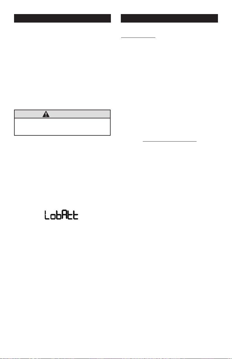
Square Wave Output
To achieve square wave output, reference Wiring Diagram 2 and use an FLSC790-BATT (sold
separately) for battery power. The terminal block
and battery location are located on the back
side of the module. Access as follows:
1. Remove the four Phillips-head screws from
the front of the module and lift the module
from the turbine.
2. To change terminal block connections,
loosen the appropriate screws. Reconnect
the wires in the proper positions and tighten
the screws.
1
Page 4
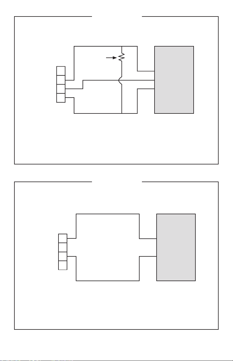
Wiring Diagram 1
+9 to 35 volt DC
Open Collector
Signal
3
2
1
4
Red
White
Black
Common
(Ground)
Terminal
Block
Customer
Interfacing
Equipment
The terminal block is identified as follows:
Pin #1 6 volt square wave (not used)
Pin #2 +9 to 35 volt DC Input
Pin #3 Common Ground
Pin #4 Open Collector signal Output
3
2
1
4
White
Black
Common
(Ground)
Terminal
Block
Customer
Interfacing
Equipment
6 volt Square
Wave Signal
The terminal block is identified as follows:
Pin #1 6 volt square wave
Pin #2 +9 to 35 volt DC Input (not used)
Pin #3 Common Ground
Pin #4 Open Collector signal Output (not used)
OPEN COLLECTOR SIGNAL OUTPUT
Resistor
(820 ohm min.)
Wiring Diagram 2
2
SQUARE WAVE OUTPUT
Page 5

3. Install the batteries. Make sure the positive
post is in the correct position.
4. Position the module on the turbine housing.
To avoid moisture damage, make sure the
seal is fully seated. Tighten the four screws
on the front of the module.
Ten feet (3 m) of cable is provided with the
module. Trim the cable to desired length or
extend it as necessary.
Verify Meter Accuracy
Before using, check the meter’s accuracy and
verify calibration.
1. Make sure there is no air in the system
by starting the flow until it runs steadily.
Then, stop or divert the flow using a valve
or nozzle.
2. Hold down DISPLAY for 3 seconds to zero
the meter’s Batch Total. When zeros appear,
release the button.
3. Meter an exact known volume into an
accurate container. For best results, meter
with one continuous full stream.
4. Check the volume against the display
or recording equipment. If the amount
metered is accurate, field calibration is not
necessary. If not, refer to the Calibration
Section for further instructions.
Batch and Cumulative Totals
The computer maintains two totals. The Cumulative Total provides continuous measurement
and cannot be manually reset. The Batch Total
can be reset to measure flow during a single
use. The Cumulative Total is labeled TOTAL 1,
Batch Total is labeled TOTAL 2 BATCH.
When the Cumulative Total reaches a display
reading of 999,999 the computer will highlight
an X10 icon. This indicates to the operator that
a zero must be added to the 6 digits shown.
When the next rollover occurs, the computer
will highlight an X100 icon. This indicates to
the operator that two zeros must be added to
the 6 digits shown.
Press the DISPLAY button briefly to switch
between the TOTAL 1, TOTAL 2 BATCH and
FLOWRATE. Press DISPLAY briefly to display
the TOTAL 2 BATCH. Hold the DISPLAY button
for 3 seconds to reset the Batch Total to zero.
When fluid is flowing through the meter, a small
propeller icon is highlighted.
Flowrate Feature
To use this feature, press and release DISPLAY
button until FLOWRATE icon appears. The
factory set time base will be highlighted to the
right of FLOWRATE (M = minutes, H = hours,
D = days). When FLOWRATE is invoked, the
display will be indicating rate of flow.
OPERATION
Computer Display
All operations are reflected in the LCD readout.
The large center digits indicate amounts, where
smaller words or “icons” located above and
below indicate specific information regarding
totals, flow, calibration and units of measure.
Activate the Meter
Computer is on continuously and always ready
to perform. The computer is powered by field
replaceable batteries. When display becomes
dim, faded or the low battery message appears
(see below), the batteries need to be replaced.
Reference the Maintenance Section for details.
Factory and Field Calibration
All calibration information is visible to the user
as icons on the top line of the display, above
the numeric digits.
All units are configured with a “factory” calibration. Both gallons and liters are available (“GL” or
“LT” will be displayed). While holding the CALIBRATE button, briefly press DISPLAY to toggle
between gallons and litres. This factory calibration (indicated with FAC) is permanently programmed into the computer and is not user adjustable.
NOTE: Your computer may have other units of
measure programmed into it. If so, holding
the CALIBRATE button and momentarily
pressing the DISPLAY button will toggle
through all factory set units. Other possible units are: IGL (imperial gallon), QT
(quart), CF (cubic feet), CM (cubic meter),
BL (42 gal. barrel), CC (cubic centimeter)
or OZ (ounce).
3
Page 6

Switching between different units will not corrupt
the Total’s contents. For example, in GL mode,
the computer totalizes 10.00 gallons, if the user
switches to LT mode, the display will read 37.85
litres (the same volume, different unit).
The “field” calibration may be set by the user,
and can be changed or modified at any time
using the calibration procedure described below
in the Calibration Section. Totals or flowrate
derived from the field calibration are invoked
when the FAC icon is no longer visible on the
top line of the display.
CALIBRATION
Verify Accuracy Before
Beginning Field Calibration
For the most accurate results, dispense at
a flowrate which best simulates your actual
operating conditions. Avoid “dribbling” more
fluid or repeatedly starting and stopping the
flow. This can result in less accurate calibrations.
Make sure you meet the meter’s minimum
flowrate requirements:
FTB690A Series Meters
1/2 inch meter 1 GPM (3.8 LPM)
3/4 inch meter 2 GPM (7.5 LPM)
1 inch meter 5 GPM (18.9 LPM)
1-1/2 inch meter 10 GPM (37.9 LPM)
2 inch meter 20 GPM (75 LPM)
The use of a uniformly dependable, accurate
calibration container is recommended for the
most accurate results. Due to high flowrate, it
is strongly recommended that calibration be
completed with a combination of volume and
weight using fine resolution scales. For best
results, the meter should be installed and purged
of air before field calibration.
Field Calibration Procedures
(Dispense/Display Method)
1. To field calibrate, press and hold CALIBRATE and DISPLAY buttons for about 3
seconds until you see FLdCAL. Release
both buttons and you will see dd000.0.
You are now in the field calibration mode.
2. Dispense a known amount of fluid at a
flowrate representative of the application.
Any amount between .1 and 999.9 units
can be used. Display will count up while
fluid is flowing through the meter.
3. The DISPLAY button can then be pushed
to select the digit location and the CALIBRATE button can be pushed to scroll the
desired value at the blinking position. Edit
the amount shown with the value that was
dispensed above. Values from 000.1 to
999.9 can be entered.
4. When satisfied with the value, press both
CALIBRATE and DISPLAY buttons simultaneously. CALEnd will be displayed and
unit will go back to normal operation, less
the FAC (factory calibration) icon.
5. The meter will now be operating with a custom calibration number unique to the above
dispense procedure. No unit of measure
(gallon, litre, etc.) icon will be highlighted.
NOTE: To return to factory calibration (FAC),
press and hold both CALIBRATION and
DISPLAY buttons for about 3 seconds, until
FAcCAL is displayed. Then release buttons.
Unit should return to normal operation and
FAC icon visible.
NOTE: If the field calibration mode is entered
and NO fluid is dispensed, then upon leaving, the computer will use data from the last
successful field calibration.
Field Calibration with
Computer Display
Field Calibration and Factory Calibration are
defined in the Operation Section. Factory
calibration settings are programmed into each
computer during manufacturing, using water
at 70° F (21° C). Readings using the Factory
Calibration (FAC) may not be accurate in some
situations, for example, under extreme temperature conditions, non-standard plumbing
configurations or with fluids other than water.
4
Page 7
MAINTENANCE
SPECIFICATIONS
Proper handling and care will extend the life
and service of the meter.
Turbine Rotor
The meter is virtually maintenance-free.
However, it is important the rotor moves freely.
Keep the meter clean and free of contaminants.
If the rotor does not turn freely, apply a penetrating lubricant on the rotor, shaft, and bearings.
Remove any debris or deposits from the rotor
using a soft brush or small probe. Be careful not
to damage the turbine rotor or supports.
CAUTION
Blowing compressed air through the turbine
assembly could damage the rotor.
Battery Replacement
The computer display is powered by two 3-volt
lithium batteries which may be replaced while
the meter is installed. When batteries are
removed or lose power, the batch and cumulative totals and the field and factory calibrations
are re tained.
If the display becomes dim, blank or the low
battery message appears (see below), replace
the batteries as follows:
1. Remove the four Phillips-head screws from
the face of the meter and lift the faceplate
from the turbine.
2. Remove the old batteries and clean any
corrosion from the terminals.
3. Install new batteries. Make sure the positive
post is in the correct position.
4. When the batteries are replaced, the faceplate will power ON. Check the display to
ensure normal functions have resumed
before assembling again.
5. Reseat batteries, if necessary, and position
the faceplate on the turbine housing.
To avoid moisture damage, make sure the
seal is fully seated. Tighten the four screws
on the faceplate.
Inlet and Outlet:
For NPT Models:
FTB691A-NPT/FTB691A-NPT-P 1/2" NPT
FTB692A-NPT/FTB692A-NPT-P 3/4" NPT
FTB693A-NPT/FTB693A-NPT-P 1" NPT
FTB694A-NPT/FTB694A-NPT-P 1-1/2" NPT
FTB695A-NPT/FTB695A-NPT-P 2" NPT
Design Type: Turbine
Wetted Components:
Housing: PVC
Journal Bearings: Ceramic
Shaft: Tungsten Carbide
Rotor and Supports: PVDF
Retaining Washer: Stainless Steel
Fitting Types: Schedule 80 NPT
Max. Working Pressure: 225 PSIG @ 73° F
U.S. Measurement
Unit of Measure: Gallon
Flow Range:
1/2 inch 1 - 10 GPM
3/4 inch 2 - 20 GPM
1 inch 5 - 50 GPM
1-1/2 inch 10 - 100 GPM
2 inch 20 - 200 GPM
Accuracy: ± 3.0% of reading (Accuracy can
be improved with field calibration)
Operating Temperature: +32° to +140° F
NOTE: Do not allow fluid to freeze inside
meter.
Storage Temperature: –40° to +158° F
Weight: (Includes Computer Display. Conditioned
Signal Module adds .30 lbs.)
1/2 inch .55 lbs.
3/4 inch .67 lbs.
1 inch .84 lbs.
1-1/2 inch 1.38 lbs.
2 inch 1.78 lbs.
Dimensions - inches (W x H x L):
(Includes Computer Display. Conditioned Signal
Module adds 1.1 inch to height)
1/2 inch 2.0 x 2.8 x 5.5
3/4 inch 2.0 x 2.9 x 5.5
1 inch 2.0 x 3.3 x 6.2
1-1/2 inch 2.3 x 3.9 x 7.6
2 inch 3.5 x 4.5 x 7.9
5
Page 8

Metric Measurement
Unit of Measure: Liter
Flow Range:
1/2 inch 3.8 - 38 LPM
3/4 inch 7.6 - 76 LPM
1 inch 19 - 190 LPM
1-1/2 inch 38 - 380 LPM
2 inch 76 - 760 LPM
Accuracy: ± 3.0% of reading (Accuracy can
be improved with field calibration)
Operating Temperature: 0° to +60° C
NOTE: Do not allow fluid to freeze inside
meter.
Storage Temperature: –40° to +70° C
Weight: (Includes Computer Display. Conditioned
Signal Module adds .14 kg)
1/2 inch .249 kg
3/4 inch .304 kg
1 inch .381 kg
1-1/2 inch .626 kg
2 inch .807 kg
Dimensions - cm (W x H x L): (Includes Com-
puter Display. Conditioned Signal Module adds
2.8 cm to height)
1/2 inch 5.0 x 7.1 x 13.9
3/4 inch 5.0 x 7.3 x 13.9
1 inch 5.0 x 8.3 x 15.7
1-1/2 inch 5.8 x 9.9 x 19.3
2 inch 8.8 x 11.4 x 20.0
PARTS
The following parts and accessories are available for the FTB690 Series meters:
Part No. Description
FLSC790-BATT Battery Replacement Kit
FTB890 O-ring O-Ring
FTB691A-NPT-RK 1/2 in., NPT, PVC, Turbine
Assembly Kit
FTB692A-NPT-RK 3/4 in., NPT, PVC Turbine
Assembly Kit
FTB693A-NPT-RK 1 in., NPT, PVC Turbine
Assembly Kit
FTB694A-NPT-RK 1-1/2 in., NPT, PVC,
Turbine Assembly Kit
FTB695A-NPT-RK 2 in., NPT, PVC Turbine
Assembly Kit
Computer Kits:
FTB691-CK 1/2 in., Computer Assy Kit
FTB692-CK 3/4 in., Computer Assy Kit
FTB693-CK 1 in., Computer Assy Kit
FTB694-CK 1-1/2 in., Computer
Assy Kit
FTB695-CK 2 in., Computer Assy Kit
6
Page 9

E S P A Ñ O L
AVISO IMPORTANTE
Utilizar los metros de los Series del FTB690
con agua y otros productos químicos que son
compatibles con les componentes que se exponen
al líquido (véase la sección de especificaciones). No utilizar para medir el incompatible
combustible o los productos químicos. Los
metros de la serie del FTB690 están disponibles
con una visualización electrónica local, o un
módulo de salida condicionado de la señal
para proporcionar una señal numérica al
equipo de interconexión del cliente. Los
medidores Series FTB690 miden en galones
o litros. Referirse a la sección de la calibración
para mayores pantalla de ordenador detalles.
Estos medidores no son legales para las
aplicaciones comerciales.
Los medidores de las Series FTB690 son muy
sensibles a interferencia electrónica si funcionan
a 1 o 2 pulgadas de algunos motores eléctricos
o de otras fuentes del uso electrónico.
Instalar su medidor en línea, u horizontalmente,
o verticalmente, o en el extremo de la manguera
adyacente al inyector. No se recomienda la
instalación a las conexiones de metal. Siga
estos pasos para instalar:
1. Planee instalar la turbina con una longitud
mínima de la pipa recta de esta manera:
– Contra la corriente de la turbina,
permita a una longitud mínima de la
– Con la corriente de la turbina, permita
una longitud mínima de la pipa recta de 5
veces el diámetro interno de la turbina.
2. Para las Conexiones del NPT cubrir las con
exiones de pipa con la vueltas de cinta del
3 a 4 veces. Cerciorarse de que la cinta no
imponga en la trayectoria del flujo.
3. Unir el metro con la flecha señalada en la
dirección del flujo.
INSTALACIÓN
pipa recta de 10 veces el diámetro
interno de la turbina.
4. Para las Conexiones del NPT utilizar
solamente sus manos para apretar las
conexiones del metro. No utilizar una llave
inglesa o una herramienta similar para
apretar. Esto puede dañar la cubierta.
Señal de Salida Condicionada
Cableado de Módulo
Este módulo de Señal de salida condicionada
se puede conectar para proporcionar una
salida de colector abierta o de señal de onda
cuadra da de 6-voltios.
Al instalar un flujómetro de la turbina de la serie
del FTB690, el factor K correcto se debe incorporar en el dispositivo de la lectura. Usted puede
encontrar el factor K impreso en el cuerpo de la
turbina. Todos los factores K en flujómetros del
Omega se calculan en pulsos por galón (PPG).
Señal de Salida de Colector Abierto
Para alcanzar una señal de salida de colector
abierto, refierase por favor al digrama eléctrico
1. El bloque de terminales está situado en
el lado trasero del módulo. El módulo viene
montado de fábrica para señal de colector
abierta. Por favor proporcionar (el resistor de
un minimo de 820 ohmios), si no es provisto
por el equipo de recepción.
Diez pies (3 m) de cable se proporcionan con el
módulo. Ajustar el cable a la longitud deseada
o extender el cable cuanto le sea necesario.
Se puede alcanzar una señal de salida de
colector abierto hasta distancias de 5.000
pies (1,524 m).
Salida de corrente de
Onda Cuadrada
Para lograr una salida de corriente de onda
cuadrada, refierase por favor al digrama eléctrico 2 y utilize un FLSC790-BATT (vendido
por separado) para la fuente de energia de la
bateria. El bloque de terminales y la localización
de la bateria están situados en el lado trasero
del modulo. Acceda al módulo de la siguiente
manera:
1. Quitar los cuatro tornillos de cabeza
Phillips del frente del módulo. Levantar el
módulo de la turbina.
7
Page 10

2. Para cambiar las conexiones del bloque
de terminales, aflojar los tornillos apropiados. Volver a conectar los alambres
en las posiciones apropiadas y apretar
los tornillos.
3. Instalar las baterias. Cerciorarse de que el
poste positivo esté en la posición correcta.
4. Colocar el módulo en la cubierta de la
turbina. Para evitar daños causados por
la humedad, cerciorarse de que el anillo
esté asentado completamente. Apretar los
cuatro tornillos en el frente del módulo.
Diez pies (3 m) de cable se proporcionan con el
módulo. Ajustar el cable a la longitud deseada
o extender el cable cuanto le sea necesario.
Verificar la Exactitud del Metro
Antes de usar, comprobar la exactitud del metro
y verificar la calibración.
1. Cerciorarse de que no haya aire en el sistema
comenzando el flujo hasta que funciona
constantemente. Entonces, detener o des-
viar el flujo mediante una válvula o la boquilla.
2. Mantenga el botón de la DISPLAY durante
3 segundos para llevar a cero el total de
medidor. Cuando aparezcan los ceros,
suelte el botón.
3. Con el medidor, mida un volumen exacto en
un envase exacto. Para mejores resultados,
medir con una corriente complete y continua.
4. Comprobar el volumen contra la pantalla o
el equipo de grabacion. Si la cantidad medi-
da es exacta, la calibración de campo no
es necesaria. Si no, refeierase a la sección
de la calibración.
OPERACIÓN
Ordenador de Pantalla
Todas las operaciones se reflejan en la lectura
del LCD. Los dígitos grandes del centro indican
cantidades, donde las palabras más pequeñas
o “iconos” que se encuentran por encima y por
debajo indican la información específica sobre
los totales, el flujo, la calibración y unidades de
medida.
Para Activar el Contador
El ordenador está encendido continuamente
y siempre dispuesto a operar. El equipo es alimentado por baterías reemplazables de campo.
Cuando la pantalla se vuelve opaco, desteñido
o el mensaje de batería baja (vea más abajo),
las baterías necesitan ser reemplazadas. Referencia de la sección de mantenimiento para
más detalles.
Lote y los Totales Acumulados
El computadora mantiene dos totales. El total
acumulativo proporciona la medida continua y
no puede ser reajustado manualmente. El total
de hornada se puede reajustar para medir el
flujo durante una sola vez. El total acumulativo
se etiqueta con el TOTAL 1 LOCKED. Esto indica que el total esta bloqueado y no puede ser
puesto a cero manualmente. l total acumulado
es etiquetado con TOTAL 1, lote total se etiqueta
TOTAL 2 BATCH.
Cuando el total acumulado llega a una lectura de
la pantalla de la computadora 999.999 resaltar
un icono de X10. Esto indica al operador que
un cero se debe agregar a los 6 dígitos que se
muestran. Cuando el traspaso se produzca la
próxima vez, el equipo se hará hincapié en un
icono X100. Esto indica al operador que dos
ceros se debe agregar a los 6 dígitos que se
muestran.
Pulse brevemente el botón DISPLAY para
cambiar entre el TOTAL 1, TOTAL 2 BATCH y la
configuración FLOWRATE. Pulse brevemente
DISPLAY para mostrar un total de TOTAL 2
BATCH. Mantenga pulsado el botón DISPLAY
durante 3 segundos para restablecer el lote
total a cero.
Cuando el líquido fluye a través del medidor, un
icono de hélice está resaltado.
Atributo del Indice de Flujo
Para utilizar esta función, pulse el botón DISPLAY y la FLOWRATE hasta que el icono aparece. La fábrica del conjunto de base de tiempo
se pondrá de relieve a la derecha del caudal de
agua (M = minutos, h = horas, D = días). Cuando
el cuadal de agua fluye, en la pantalla se indica
la velocidad de flujo.
8
Page 11

Calibración de Campo de Fábrica
Toda la información de calibración es visible
para el usuario como iconos en la línea superior de la pantalla, por encima de los dígitos
numéricos.
Todas las unidades están configurados con una
calibración de fabrica. Ambos galones y litros
están disponibles (“GL” o “LT” se mostrará).
Mientras mantiene el botón CALIBRATE, pulse
DISPLAY para cambiar entre galones y litros.
Esta calibración de fábrica (se indica con FAC)
está programada permanentemente en la computadora y no es ajustable por el usuario.
NOTA: El equipo puede tener otras unidades
de medida programada en ella. Si es así,
manteniendo pulsado el botón CALIBRATE
y momentáneamente pulsando el botón
DISPLAY, se activará a través de todas las
unidades de conjunto de la fábrica. Otras
unidades posibles son: IGL (galón imperial),
QT (cuarto), CF (pies cúbicos), CM (metros
cúbicos), BL (42 gal. Barril), CC (centímetros
cúbicos) o OZ (onzas).
El cambiar entre diferentes unidades no dañará
el Total. Por ejemplo, en el modo de GL, el equipo totaliza 10,00 galones, si el usuario cambia
a modo de LT, la pantalla se leerá 37,85 litros
(el mismo volumen, las diferentes unidades).
Los “campos” de calibración pueden ser configurados por el usuario, y puede ser cambiado
o modificado en cualquier momento mediante
el procedimiento de calibración se describe a
continuación en la sección de calibración. De
los totales o caudal de agua derivada de la
calibración de campo se invoca cuando el icono
de la FAC ya no es visible en la línea superior
de la pantalla.
Cerciorese de reunir todos los requisitos mínimos del índice de flujo del medidor:
Medidores de las Series del FTB690A
Medidor de 1/2 pulgada de
1 GPM (3,8 LPM)
Medidor de 3/4 pulgada de
2 GPM (7,5 LPM)
Medidor de 1 pulgada de
5 GPM (18,8 LPM)
Medidor de 1-1/2 pulgadas de
10 GPM (37,85 LPM)
Medidor de 2 pulgadas de
20 GPM (75 LPM)
Se recomienda para resultados más exactos
de la calibración el uso de un envase uniforme,
confiable, y exacto. Debido al alto indice de flujo,
se recomienda que la calibración esté terminada
con una combinación de volumen y de peso
usando escalas de alta resolución. Para mejores
resultados, el medidor se debe instalar y purgar
del aire antes de la calibración de campo.
Calibración de Campo con
Ordenador de Pantalla
La calibración de campo y de fábrica se definen
en la Sección de Operaciones. Parámetros de
calibración de fábrica son personalizados programado en cada equipo durante la fabricación,
el uso de agua a 70° F (21° C). Lecturas utilizando la calibración de fábrica (FAC), puede no
ser exacta en algunas situaciones, por ejemplo,
bajo condiciones de temperatura extrema, las
configuraciones de plomería estándar o con
otros líquidos distintos del agua.
CALIBRACIÓN
Favor de Verificar la Precisión
Antes de Iniciar la Calibración de
Campo
Para resultados más exactos, dispense un
índice de flujo que simule lo mejor posible sus
condiciones de funcionamiento reales. Evite “de
gotear” más líquido o en varias ocasiones, o el
comenzar y de parar el flujo. Estas acciones
darán lcomo resultado calibraciones menos
exactas.
9
Page 12

Procedimientos de Calibración
de Campo (Método de Dispensar/
Visualización)
1. Para calibración de campo, presione y
mantenga los botones de CALIBRATE y
DISPLAY durante unos 3 segundos hasta
que aparezca FLdCAL. Suelte los botones
y podrás ver dd000.0. Ahora está en el
modo de calibración de campo.
2. Prescindir de una cantidad conocida de
fluido a un caudal representativo del de la
aplicación. Cualquier cantidad entre .1 y
999,9 unidades pueden ser utilizados. La
pantalla se encargará de contar mientras
el líquido fluye a través del medidor.
3. El botón DISPLAY puede ser presionado
para seleccionar la ubicación de dos dígitos y el botón CALIBRATE se puede presionar para desplazar el valor deseado
en la posición que parpadea. Modificar
el importe que figura con el valor que se
dispensó anteriormente. Se pueden utlizar
valores de 000.1 a 999.9.
4. Cuando esté satisfecho con el valor, pulse
dos botones CALIBRATE y DISPLAY simultáneamente. CALEnd se mostrará y la
unidad volverá al funcionamiento normal,
menos el icono de la FAC (calibración de
fábrica).
5. El medidor estará operando con un núme-
ro de calibración personalizada única
al anterior procedimiento. No resaltará
ningún icono de unidad de medida (galón,
litro, etc).
NOTA: Para volver a la calibración de fábrica
(FAC), presione y mantenga los botones
de pantalla de CALIBRATION y DISPLAY
durante unos 3 segundos, hasta que
se muestre FAcCAL. Inmediatamente
después suelte los botones. La Unidad
debe volver al funcionamiento normal y el
icono de FAC debe estar visible de nuevo.
NOTA: Si durante el modo de calibración de
campo NO se introduce ni se dispensa
líquido alguno, al concluir el equipo utilizará los datos de calibración, de la última
calibración de campo exitosa.
MANTENIMIENTO
La utilización y el cuidado apropiados ampliarán
la vida y el servicio del medidor.
Rotor de Turbina
El medidor practicamente no tiene necesidad
de mantenimiento. Sin embargo, es importante
que los movimientos del rotor ocurran libremente. Mantener el medidor limpio y libre de
contaminantes.
Si el rotor no da vuelta libremente, aplicar
un lubricante penetrante en el rotor, el eje, y
los rodamientos. Quitar cualquier desecho o
depósito del rotor usando un cepillo suave o una
punta de prueba pequeña. Tenga cuidado de
no dañar el rotor de turbina o los soportes.
PRECAUCIÓN
El aire comprimido a través del montaje de
la turbina podría dañar el rotor.
Reemplazo de la Batería
La pantalla del ordenador se alimenta de
dos pilas de litio de 3-voltios, que podrá ser
sustituido mientras se instala el medidor.
Cuando las baterías se quitan o pierden la
potencia, la hornada y los totales acumulativos
seran reajustados a cero, pero las calibraciones
de campo y de la fábrica se conservan.
Si la pantalla se vuelve oscura, en blanco o
el mensaje de batería baja (vea más abajo),
reemplazar las baterías de la siguiente manera:
1. Quitar los cuatro tornillos de la cara del
metro y levantar la placa frontal de la
turbina.
2. Quitar las viejas baterías y limpiar cualquier
corrosión de los terminales.
3. Instalar las baterías nuevas. Cerciorarse de
que el poste positivo esté en la posición
correcta.
4. Cuando se substituyen las baterías, la
placa frontal estará encendida. Comprobar
la exhibición para asegurarse de que las
funciones normales han resumido antes
de montar otra vez.
10
Page 13

5. Volver a sentar las baterías, en caso
necesario, colocar la placa frontal en la
cubierta de la turbina. Evite el daño
causado por la humedad, cerciorarse de
que el anillo esté asentado completamente.
Apretar los cuatro tornillos en la placa
frontal.
ESPECIFICACIONES
Entrada y Enchufe:
Por NPT Modelos:
FTB691A-NPT/FTB691A-NPT-P 1/2" de NPT
FTB692A-NPT/FTB692A-NPT-P 3/4" de NPT
FTB693A-NPT/FTB693A-NPT-P 1" de NPT
FTB694A-NPT/FTB694A-NPT-P 1-1/2" de NPT
FTB695A-NPT/FTB695A-NPT-P 2" de NPT
Tipo del Diseño: Turbina
Componentes Mojados:
Cubierta: PVC
Rodamientos: De Cerámica
Eje: Carburo de Tungsteno
Rotory Soportes: PVDF
Arandela De Retención: Stainless Steel
Tipo de las Guarnicione: Resbalón de 80 NPT
Máxima Presión de Funcionamiento:
225 PSIG a los 73°F
Medida de Estados Unidos
Unidad de la Medida: Galón
Gama del Flujo:
1/2" 1 - 10 GPM
3/4" 2 - 20 GPM
1" 5 - 50 GPM
1-1/2" 10 - 100 GPM
2" 20 - 200 GPM
Exactitud: ±3.0% de la lectura (la exactitud se
puede mejorar con la calibración del
campo)
Temperatura de Funcionamiento:
+32° a +140° F
NOTA: No permitir que el líquido
congele dentro del metro.
Temperatura del Almacenaje:
-40° a +158° F
Peso: (Incluye pantalla de ordenader. Módulo de
Señal de salida condicionada añade .30 libras.)
1/2" ,55 libras
3/4" ,67 libras
1" ,84 libras
1-1/2" 1,38 libras
2" 1,78 libras
Dimensiones - Pulgadas (Grosor x Altura x
Longitud):
(Incluye pantalla de ordenader. Módulo de
Señal de salida condicionada añade 1.1 altura.)
1/2" 2,0 x 2,8 x 5,5
3/4" 2,0 x 2,9 x 5,5
1" 2,0 x 3,3 x 6,2
1-1/2" 2,3 x 3,9 x ,67
2" 3,5 x 4,5 x 7,9
Medida Métrica
Unidad de la Medida: Litro
Gama del Flujo:
1/2" 3,8 - 38 LPM
3/4" 7,6 - 76 LPM
1" 19 - 190 LPM
1-1/2" 38 - 380 LPM
2" 76 - 760 LPM
Exactitud: ±3.0% de la lectura (la exactitud se
puede mejorar con la calibración del
campo)
Temperatura de Funcionamiento:
0° a +60° C
NOTA: No permitir que el líquido
congele dentro del metro.
Temperatura del Almacenaje:
-40° a +70° C
Peso: (Incluye pantalla de ordenader. Módulo
de Señal de salida condicionada añade .14 kg.)
1/2" .249 kilogramo
3/4" .304 kilogramo
1" .381 kilogramo
1-1/2" .626 kilogramo
2" .807 kilogramo
Dimensiones - Centímetro
(Grosor x Altura x Longitud):
(Incluye pantalla de ordenader. Módulo de
Señal de salida condicionada añade 2.8 cm.)
1/2" 5,0 x 7,1 x 13,9
3/4" 5,0 x 7,3 x 13,9
1" 5,0 x 8,3 x 15,7
1-1/2" 5,8 x 9,9 x 19,3
2" 8,8 x 11,4 x 20,0
11
Page 14

PIEZAS
Las piezas y los accesorios siguientes de
recambio están disponibles para los medidores
de los Series del FTB690A:
Parte No. Descripción
FLSC790-BATT Systema de reemplazo de
la batería
FTB890 O-Ring Anillo-O
FTB691A-NPT-RK 1/2" NPT, PVC - kit de la
assamblea de la turbina
FTB692A-NPT-RK 3/4" NPT, PVC - kit de la
assamblea de la turbina
FTB693A-NPT-RK 1" NPT, PVC - kit de la
assamblea de la turbina
FTB694A-NPT-RK 1-1/2" NPT, PVC - kit de la
assamblea de la turbina
FTB695A-NPT-RK 2" NPT, PVC - kit de la
assamblea de la turbina
Kits de la Computadora:
FTB691-CK 1/2" - kit de la asamblea
de la computadora
FTB692-CK 3/4" - kit de la asamblea
de la computadora
FTB693-CK 1" - kit de la asamblea de
la computadora
FTB694-CK 1-1/2" - kit de la asamblea
de la computadora
FTB695-CK 2" - kit de la asamblea de
la computadora
D E U T S C H
WICHTIGE NACHRICHT
Die FTB690 Series Meßinstrumente mit
Wasser und anderen Chemikalien benutzen,
die mit Bestandteilen kompatibel sind, die
Flüssigkeit (Spezifikationen Abschnitt sehen).
Verwenden Sie nicht zu Meter von Kraftstoff
ofer chemikalien unvereinbar. Die FTB690 Reihe
Meßinstruments sind vorhanden entweder mit
einer lokalen elektronischen Anzeige oder einer
konditionierten Signalausgabebaugruppe, ein
digitales Signal zum Kunde Schnittstellenmodul
zur Verfügung zu stellen. FTB690 Series mißt
in Gallonen oder Litern. Auf den Kalibrierungsabschnitt Computer mit Anzeige für Beiwek
beziehen.
Diese Meßinstrumente sind nicht für den
Handel zulässig.
FTB690 Series Meßinstrumente sind gegen
elektronische Störung sehr empfindlich, wenn
sie innerhalb 2,5 bis 5 cm einiger Elektromotoren oder anderer Quellen des elektronischen Gebrauches bedient werden.
INSTALLATION
Ihr Meßinstrument inline entweder am Ende des
Schlauches neben der Düse horizontal oder
vertikal anbringen. Installation zu Metallanschlüssen wird nicht empfohlen. Diesen
Schritten folgen, um anzubringen:
1. Planen, die Turbine mit einer minimalen
Länge geraden Rohres anzubringen:
– Gegen den Strom von der Turbine, einer
minimalen Länge des geraden Rohres
von 10mal dem internen Durchmesser
der Turbine erlauben.
– Stromabwärts von der Turbine, eine
minimale Länge des geraden Rohres
von 5mal dem inneren Durchmesser
der Turbine erlauben.
2. Für NPT Befestigungen spule Klebeband
3 bis 4 mal um die Pipe-Verbindungen.
Sicherstellen, daß das Klebeband nicht
das Innere des Rohres berührt.
12
Page 15

3. Das Meßinstrument mit dem Pfeil anbringen,
der in die Richtung des Flusses zeigt.
4. Für NPT Befestigungen nur Ihre Hände
benutzen um die Pipe-Verbindun. Wenn Sie
die Anschlüsse festziehen, sich erinnern,
keine Werkzeuge zu benutzen.
Konditioniertes Signal Ausgeben
Baugruppenverdrahtung
Diese konditionierte Signalausgabebaugruppe
kann verdrahtet werden, um einen geöffneten
Kollektorsignal-Ausgang oder Welle des Quadrats 6-volt Ausgang zur Verfügung zu stellen.
Wenn man ein FTB690 Reihe Turbineströmungsmesser anbringt, muß der korrekte KFaktor in die Auslesenvorrichtung eingetragen
werden. Sie Können den K-Faktor finden
gedruckt auf dem Turbinekörper. Alle K-Faktoren
auf Omega Strömungsmessern werden in den
impulsen pro Gallone (PPG).
Öffnen Kollektor-Signal-Ausgang
Um einen geöffneten Kollektor Ausgang zu
erzielen, Bezugsbauschaltplan 1 signalisieren.
Der Klemmenblock ist auf der Rückseite des
Moduls. Das Modul ist die Fabrik, die für geöffneten Kollektorsignalausgang. Bitte geben sie
die (820-Ohm-Minimum) Widerstand, wenn
nicht durch den Empfang Ausrüstung geliefert.
10 Fuß (3 m) Kabel wird mit dem Modul.
Versehen Das Kabel zur gewünschten Länge
trimmen oder das Kabel wie benötigt verlängern. Abstände bis 5.000 Fuß (1,524 m) könne
für geöffneten Kollektorsignalausgang erzielt
werden.
Quadratischer Welle Ausgang
Um Quadratischen Welle Ausgang zu erzielen,
Bezugsbauschaltplan 2 signalisieren und einen
FLSC790-BATT (separat verkauft) für die Batterieleistung benutzen. Der Klemmenblock und
die Batterieposition sind auf der Rückseite des
Moduls. Zugang wie folgt:
1. Die vier Kreuzkopfschrauven von der Frontseite des Moduls entfernen. Das Modul von
der Turbine anheben.
2. Um die Klemmenblockanschlüsse zu
ändern, die passenden Schrauben lösen.
Die Leitungen in den korrekten Positionen
wieder anschließen und die Schrauben
festziehen.
3. Die Batterien anbringen. Sicherstellen,
daß der positive Pfosten in der richtigen
Position ist.
4. Das Modul auf das Turbinegehäuse in Position bringen. Um Feuchtigkeit Beschädigung zu vermeiden, sicherstellen daß der
Dichtung völlig setzt. Die vier Schrauben
an der Frontseite des Moduls festziehen.
10 Fuß (3 m) Kabel wird mit dem Modul versehen. Das Kabel zur gewünschten Länge trimmen
oder das Kabel wie benötigt verlängern.
Meßinstrument Genauigkeit
Überprüfen
Bevor Sie verwenden, die Genauigkeit des
Meßinstruments überprüfen und die Kalibrierung überprüfen.
1. Stellen Sie sicher, dass keine Luft in
das System, indem Sie die Flüssigkeit
durch den Zähler, bis die Flüssigkeit läuft
kontinuierlich. Dann, zu stoppen oder
umzuleiten den Fluss mit einem Ventil oder
eine Düse.
2. Ha lten Sie die DISPLAY-Tast e für 3
Sekunden, damit die Messgeräts Batch
Insgesamt werden auf Null gesetzt
werden. Wenn null erscheint, die Taste
freigeben.
3. Das Meßinstrument ein genau bekanntes
Volumen in einen genauen Behälter abgeben lassen. Für beste Resultate mit einem
ununterbrochenen vollen Strom messen.
4 Das Vojumen gegan die Anzeige order
die Aufnahmeausrüstung überprüfen.
Wenn die Menge, die gemessen wird,
genau ist, ist Nacheichung nicht notwendig.
Wenn nicht, auf den Kalibrierungsabschnitt
für weitere Anweisungen beziehen.
13
Page 16

BETRIEB
Computer-Display
Alle Operationen werden in der LCD-Anzeige
wieder. Das große Zentrum Ziffern geben
Mengen, in denen kleinere Wörter oder
“Ikonen” befindet sich oben und unten zeigen,
spezifische Informationen über die Summen,
Durchfluss-, Kalibrier-und Maßeinheiten.
Aktivieren Sie die Meter
Computer wird weiterhin kontinuierlich und
immer bereit zu erfüllen. Der Computer ist
durch Feld-powered austauschbaren Batterien.
Wenn die Anzeige schwach, schwach oder die
Batterie-Meldung angezeigt wird (siehe unten),
müssen die Batterien ausgetauscht werden.
Verweisen Sie auf die Wartung Abschnitt für
Details.
Batch-und Gesamtsummen
Der Computer verwaltet zwei Summen. Der
kumulierte Betrag stellt die kontinuierliche
Messung und kann nicht manuell zurückgesetzt
werden. Der Batch Insgesamt kann zurückgesetzt werden, fließen in einer einzigen Anwendung zu messen. Der kumulierte Betrag ist mit
TOTAL 1 bezeichnet, ist Batch Total beschriftet
TOTAL 2 BATCH.
Wenn der kumulierte Betrag erreicht eine Anzeige Lesung 999.999 der Computer wird ein
X10-Symbol zu markieren. Dies deutet darauf
hin, dass dem Betreiber eine Null an die 6
gezeigten Ziffern hinzugefügt werden. Wenn
die nächste Rollover auftritt, wird der Computer
ein Highlight X100-Symbol. Diese zeigt dem
Bediener, dass zwei Nullen an die 6 gezeigten
Ziffern hinzugefügt werden.
Drücken Sie die DISPLAY-Taste kurz, um
zwischen den insgesamt 1, TOTAL 2 BATCH
und FLOWRATE. Drücken Sie DISPLAY, um
die kurz TOTAL 2 BATCH. Halten Sie die
DISPLAY-Taste für 3 Sekunden wieder auf die
Batch-Total auf Null.
Wenn die Flüssigkeit fließt durch das Messgerät,
ein kleiner Propeller-Symbol markiert ist.
Durchfluss Funktion
Um diese Funktion, drücken Sie DISPLAY
verwenden, bis FLOWRATE-Symbol erscheint.
Die Fabrik eingestellten Zeit wird auf Basis des
Rechts der FLOWRATE hervorgehoben werden
(M = Minuten, H = Stunden, D = Tage). Wenn
FLOWRATE aufgerufen wird, wird das Display
um darauf hinzuweisen, Fließgeschwindigkeit.
Betriebs-und Kalibriersoftware
Alle Kalibrier-Informationen für den Benutzer
sichtbar als Symbole in der oberen Zeile des
Displays, über die Ziffern.
Alle Einheiten sind mit einer “Fabrik” Kalibrierung konfiguriert werden. Beide Gallonen und
Liter stehen zur Verfügung ( “GL” oder “LT”
wird angezeigt). Halten Sie die Schaltfläche
CALIBRATE, drücken Sie kurz DISPLAY, um
zwischen Gallonen und Liter zu wechseln.
Diese Fabrik-Kalibrierung (mit FAC angegeben)
ist fest in den Computer programmiert und
kann nicht vom Benutzer einstellbar.
HINWEIS: Ihr Computer ist möglicherweise
auch andere Maßeinheiten in sie programmiert. Wenn ja, hält die Schaltfläche
CALIBRATE und momentan Drücken der
DISPLAY-Taste wird durch alle werkseitig
eingestellt Einheiten zu wechseln. Andere
mögliche Einheiten sind: IGL (Imperial Gallonen), QT (Quart), CF (Kubikmeter), CM
(Kubikmeter), BL (42 gal. Barrel), CC (Kubikzentimeter) oder OZ (Unzen).
Wechseln zwischen verschiedenen Einheiten
werden nicht beschädigt die Total-Inhalten.
Zum Beispiel, im OpenGL-Modus, den Computer summiert 10,00 Gallone, wenn der
Benutzer schaltet in den LT, erscheint auf dem
Display 37,85 Liter (das gleiche Volumen, verschiedene Einheit) zu lesen.
Das “Feld” Kalibrierung kann vom Anwender
eingestellt werden und kann geändert werden,
oder jederzeit über das Kalibrierverfahren um
nachstehend beschriebenen Abschnitt der
Kalibrierung. Summen bzw. aus dem Bereich
Kalibrierung Durchfluss abgeleitet werden
aufgerufen, wenn der FAC-Symbol nicht mehr
sichtbar in der oberen Zeile des Displays wird.
14
Page 17

CALIBRATION
Vor Dem Beginn Der Nacheichung
Für die genauesten Resultate an einer Fließgesc h w i n digkeit zufüh ren, di e gut Ihre
tatsächlichen Betriebsbedingungen simuliert.
Vermeiden, mehr Flüssigkeit “zu tröpfeln”
oder wiederholt den Fluß zu beginnen und zu
stoppen. Diese Vorgänge ergeben weniger
genaue Kalibrierungen.
Versichern Sie sich, dass Sie die minimalen
Fließgeschwindigkeiten des Meßinstruments
erreichen:
FTB690A Series Meßinstrumente
1/2 Zoll 1 GPM (3,8 LPM)
3/4 Zoll 2 GPM (7,5 LPM)
1 Zoll 5 GPM (18,8 LPM)
1-1/2 Zoll 10 GPM (37,85 LPM)
2 Zoll 20 GPM (75 LPM)
Der Gebrauch eines gleichmäßig zuverlässigen,
genauen Kalibrierung Behälters wird in hohem
Grade für die genauesten Resultate empfohlen.
Wegen der hohen Fließgeschwindigkeit, wird
es stark empfohlen, daß Kalibrierung mit einer
Kombination des Volumens und des Gewichts
mit feine Auflösung Skalen durchgeführt wird.
Für beste Resultate sollte das Meßinstrument
angebracht werden und bereinigt worden von
der Luft vor Kalibrierung auffangen.
Feld Kalibrierung mit
Computer-Display
Field Kalibrierung und Kalibrierung sind an der
Operation Abschnitt definiert. Werkskalibrierung
Einstellungen sind in jedem Computer während
der Herstellung programmiert, unter Verwendung von Wasser bei 70° C (21° C). Messwerte mit
Hilfe der Factory Calibration (FAC) ist möglicherweise nicht in einigen Situationen richtig, zum
Beispiel unter extremen Temperaturbedingungen, Nicht-Standard-Sanitär-Konfigurationen
oder mit anderen Medien als Wasser.
2. Dispense eine bekannte Menge von Flüssigkeit bei einem Durchfluß, Vertreter der
Anwendung. Jeder Betrag zwischen .1
und 999,9 Einheiten verwendet werden
kann. Anzeige zählt, solange Flüssigkeit
fließt durch den Zähler.
3. Die DISPLAY-Taste können dann geschoben werden, um die Position der Ziffer
auswählen und die Schaltfläche Kalibrieren geschoben werden können, um den
gewünschten Wert an der blinkenden Position zu blättern. Bearbeiten Sie den Betrag mit dem Wert, der oben gezeigt wurde
verzichtet. Werte von 000,1 bis 999,9
eingegeben werden können.
4. Wenn Sie zufrieden sind mit dem Wert,
drücken Sie beide CALIBRATE und
DISPLAY Tasten gleichzeitig. CALEnd
wird angezeigt und Gerät zurück zum
normalen Betrieb, abzüglich der FAC
(Werkskalibrierung)-Symbol.
5. Das Gerät ist nun in Betrieb sein mit einer benutzerdefinierten Kalibrierung eine
einmalige Nummer, die oben genannten
Verfahren zu verzichten. Nr. Maßeinheit
(Gallonen, Liter usw.) Symbol wird hervorgehoben.
Hinweis: Um wieder auf die werkseitigen Ka-
librierung (FAC), drücken und halten Sie
beide CALIBRATE und DISPLAY-Taste
etwa 3 Sekunden, bis FAcCAL angezeigt
wird. Dann Entriegelungstasten. Einheit
sollte Rückkehr zum normalen Betrieb und
die FAC-Symbol sichtbar.
HINWEIS: Wenn das Feld der Betriebsart
Kalibrierung eingetragen ist, und keine
Flüssigkeit verzichtet wird, dann beim
Verlassen, wird der Computer Daten aus der
letzten erfolgreichen Kalibrierung vor Ort.
WARTUNG
Field Calibration Procedures
(Dispense / Display-Methode)
1. So kalibrieren, drücken Sie bei gedrückter
CALIBRATE und DISPLAY-Taste etwa 3
Sekunden, bis Sie FLdCAL sehen können.
Lassen Sie beide Tasten, und Sie werden
dd000.0 sehen. Sie befinden sich nun im
Bereich der Betriebsart Kalibrierung.
Die korrekte Behandlung und die Wartung
verlängern das Leben und den Service des
Meßinstruments.
15
Page 18

Turbinenrotor
Das Meßinstrument ist praktisch wartungsfrei.
Jedoch ist es wichtig, dass sich der Rotor frei
bewegen kann. Das Meßinstrument sauber
halten und von Verunreinigung freihalten.
Wenn der Läufer sich nicht frei dreht, ein
Durchdringungsschmiermittel auf dem Läufer,
der Welle und den Wellenlagern anwenden.
Allen möglichen Rückstand oder Ablagerungen
vom Läufer mit einer weichen Bürste oder
einem kleinen Fühler entfernen. Achtgeben, daß
Sie nicht den Turbinenrotor oder die Stützen
beschädigen.
VORSICHT
Pressluft durch die Turbine blasen kann den
Rotor beschädigen.
BatterieAustausch
Das Computer-Display wird durch zwei 3-Volt
Lithium-Batterien, die ersetzt werden kann,
während das Gerät installiert ist. Die Zwischensummen und kumulativen Gesamtmengen
stellen sich auf Null zurück, wenn die Batterien
schwach werden oder entfernt worden sind.
Die Fabrik- und Nacheichung bleibt erhalten.
Wenn die Anzeige schwächer wird, leer oder
die Batterie-Meldung (siehe unten), ersetzen
Sie die Batterien wie folgt:
1. Die vier Kreuzschlitzschrauben von der
Vorderseite des Meßinstruments entfernen
und die Frontplatte von der Turbine
anheben.
2. Die alten Batterien entfernen und jede
mögliche Korrosion von den Klemmen
säubern.
3. Neue Batterien anbringen. Überprüfen, daß
der positive Pfosten in der richtigen Posi-
tion ist.
4. Wenn die Batterien ausgetauscht sind,zeigt
die Frontplatte “POWER ON”. Die Anzeige
überprüfen, um normale Funktionen sicherzustellen, bevor Sie wieder zusammenbauen.
16
5. Falls nötig, Batterieeinsetzung berichtigen,
und die Frontplatte auf das Turbinegehäuse
in Position bringen. Um Feuchtigkeit-
sbeschädigung zu vermeiden, überprüfen,
daß der Dichtung völlig sitzt. Die vier
Schrauben an der Frontplatte festziehen.
SPEZIFIKATIONEN
Eingang und Anschluß:
Für NPT-Modelle:
FTB691A-NPT/FTB691A-NPT-P 1/2" NPT
FTB692A-NPT/FTB692A-NPT-P 3/4" NPT
FTB693A-NPT/FTB693A-NPT-P 1" NPT
FTB694A-NPT/FTB694A-NPT-P 1-1/2" NPT
FTB695A-NPT/FTB695A-NPT-P 2" NPT
DesignBaumuster: Turbine
Naßgemachte Bauteile:
Gehäuse: PVC
Achslager: Keramisch
Welle: Hartmetall
Läufer und Halterungen: PVDF
Haltering: Rostfreier Stahl
Verbindungstyp: Zeitplan 80 NPT
Max. FunktionsDruck: 225 PSIG @ 73° F
U.S. Maß
Maßeinheit der Maßnahme: Gallone
FlußStrecke:
1/2" 1 - 10 GPM
3/4" 2 - 20 GPM
1" 5 - 50 GPM
1-1/2" 10 - 100 GPM
2" 20 - 200 GPM
Genaui g k e i t : ± 3.0% lesegenauigkeit
(Genauigkeit kann mit verbessert werden
auffangen Kalibrierung)
Betriebstemperatur: +32° zu +140° F
ANMERKUNG: Flüssigkeit nicht innerhalf
des Meßinstruments einfrieren lassen
SpeicherTemperatur: -40° zu +158° F
Gewicht:
(Eingeschlossen sind Computer-Display.
Korditioniertes Signal Ausgeben modul fügt .30
Pfund.)
1/2" ,55 Pfund
3/4" ,67 Pfund
1" ,84 Pfund
1-1/2" 1,38 Pfund
2" 1,78 Pfund
Page 19

Abmessungen - Zoll (W x H x L):
(Eingeschlossen sind Computer-Display.
Korditioniertes Signal Ausgeben modul fügt 1,1
Zoll bis Höhe.)
1/2" 2,0 x 2,8 x 5,5
3/4" 2,0 x 2,9 x 5,5
1" 2,0 x 3,3 x 6,2
1-1/2" 2,3 x 3,9 x 7,6
2" 3,5 x 4,5 x 7,9
Metrisches Maß
Maßeinheit: Liter
FlußStrecke:
1/2" 3,8 - 38 LPM
3/4" 7,6 - 76 LPM
1" 19 - 190 LPM
1-1/2" 38 - 380 LPM
2" 76 - 760 LPM
Genaui g k e i t : ± 3.0% lesegenauigkeit
(Genauigkeit kann mit verbessert werden
auffangen Kalibrierung)
Betriebstemperatur: 0° zu +60° C
ANMERKUNG: Flüssigkeit nicht innerhalf
des Meßinstruments einfrieren lassen
SpeicherTemperatur: -40° zu +70° C
Gewicht:
(Eingeschlossen sind Computer-Display.
Korditioniertes Signal Ausgeben modul fügt
.14 kg)
1/2" .249 Kilogramm
3/4" .304 Kilogramm
1" .381 Kilogramm
1-1/2" .626 Kilogramm
2" .807 Kilogramm
Abmessungen - Zentimeter (W x H x L):
(Eingeschlossen sind Computer-Display.
Korditioniertes Signal Ausgeben modul fügt
2.8 cm bis Höhe.)
1/2" 5,0 x 7,1 x 13,9
3/4" 5,0 x 7,3 x 13,9
1" 5,0 x 8,3 x 15,7
1-1/2" 5,8 x 9,9 x 19,3
2" 8,8 x 11,4 x 20,0
TEILE
Die folgenden Ersatzteile und die Zusatzgeräte
sind für die FTB690 Series Meßinstrumente
vorhanden:
Teil Nr. Beschreibung
FLSC790-BATT Batterie Austausch lnstallationssatz
FTB890 O-Ring O-Ring
FTB691A-NPT-RK 1/2 Zoll, NPT, PVC, Turbine einheitsinstallationssatz
FTB692A-NPT-RK 3/4 Zoll, NPT, PVC, Turbine einheitsinstallationssatz
FTB693A-NPT-RK 1 Zoll, NPT, PVC, Turbine einheitsinstallationssatz
FTB694A-NPT-RK 1-1/2 Zoll, NPT, PVC,
Turbineeinheitsinstalla tionssatz
FTB695A-NPT-RK 2 Zoll, NPT, PVC, Turbine einheitsinstallationssatz
Computereinheitsinstallationssatz:
FTB691-CK 1-/2 Zoll, Computereinheit sinstallationssatz
FTB692-CK 3/4 Zoll, Computereinheit sinstallationssatz
FTB693-CK 1 Zoll, Computereinheit sinstallationssatz
FTB694-CK 1-1/2 Zoll, Computerein heitsinstallationssatz
FTB695-CK 2 Zoll, Computereinheit sinstallationssatz
17
Page 20

I T A L I A N O
AVVISO IMPORTANTE
Usare i tester dei Series del FTB690 con acqua
ed altri prodotti chimici che sono compatibili
con le parti che sono esposti a liquido (vedere
la sezione di specifiche). Non usare misurare il
combustibile o incompatibili o i prodotti chimici.
I contametri di serie FTB690 sono a disposizione
con una Visualizzazione elettronica locale, o un
modulo di uscita condizionato del segnale per
fornire un segnale numerico all’apparecchiatura
di collegamento del cliente. I Series di FTB690
misura la misura con un contatore nei galloni
o nei litri. Riferirsi alla taratura con display del
computer di sezione per i particolari.
Questi tester non sono per le applicazioni
commerciali.
I tester dei Series del FTB690 sono molto
sensibili ad interferenza elettronica se sono
funzionati all’interno di 1 - 2 pollici di alcuni
motori elettrici o di altre fonti di uso elettronico.
Installare il vostro tester in linea orizzontalmente
o verticalmente o all’estremità del tubo flessibile
adiacente all’ugello. L’installazione ai collegamenti del metallo non è suggerita. Seguire questi
punti per installare:
1. Progettare installare la turbina con una
– A monte dalla turbina, concedere ad
– A valle dalla turbina, concedere ad una
2. Per i Montaggi del NPT circondare i
3. Fissare il tester con la freccia indicata nel
4. Per i Montaggi del NPT utilizzare soltanto
INSTALLAZIONE
lunghezza minima del tubo diritto:
una lunghezza minima di un tubo diritto
di 10 volte il diametro interno della
turbina.
lunghezza minima di un tubo diritto di 5
volte il diametro interno della turbina.
collegamenti di tubo con giri di nastri
adesivi del 3-4 volte.
senso del flusso.
le vostre mani per stringere i collegamenti.
Non utilizzare gli attrezzi per stringere. Ciò
può causare danni.
Segnale Condizionato Produrre
Cablaggio di Modulo
Questo modulo di segnale condizionato del
può essere legato per fornire del collettore
dell’ segnale aperta o dell’onda del quadrato
di 6-volti.
Nell’installare un flussometro della turbina
di serie di FTB690, il fattore K corretto deve
essere inserito nel dispositivo della lettura.
Potete trovare il fattore K stampato sul corpo
della turbina. Tutti i fattore K sui fludssometri
del Omega sono calcolati negli impulsi per il
gallone (PPG).
Collettore dell’Segnale Aperta
Per raggiungere Collettore dell’ Segnale Aperta,
Riferiscasi allo schema elettrico di riferimento
1. Il blocchetto terminali è situato dal lato pos-
teriore del modulo. Il modulo è fabbrica montata per collettore dell’ segnale aperta. Fornire
prego il resistore di minimo di 820 Ohm, se non
è fornito dall’apparecchiatura di ricezione.
Dieci piedi (3 m) di cavo è fornito del modulo.
Assettare il cavo alla lunghezza voluta o estendere il cavo come necessario. Le distanze fino a
5,000 piedi (1,524 m) possono essere realizzate
per l’collettore dell’ segnale aperta.
Segnale dell’Onda Quadrata
Per raggiungere segnale dell’Onda Quadrata,
Riferiscasi allo schema elettrico di riferimento
2 ed usare FLSC790-BATT (venduto esclusivamente) per la potenza della batteria. Il blocchetto terminali e la posizione della batteria
sono situati dal modulo. Accesso come segue:
1. Rimuovere le quattro viti Phillips dalla parte
anteriore del modulo. Alzare il modulo dalla
turbina.
2. Per cambiare i collegamenti del blocchetto
terminali, allentare le viti adatte. Ricollegare
i legare nelle posizioni adequate e stringere
le viti.
3. Installare le batterie. Assicurarsi che l’alberino positivo è nella posizione corretta.
4. Posizionare il modulo sull’alloggiamento
della turbina. Evitare danni dell’umidità,
assicurarsi che l’anello completamente è
messo. Stringere le quattro viti sulla parte
anteriore del modulo.
18
Page 21

Dieci piedi (3 m) di cavo è fornito del modulo.
Assettare il cavo alla lunghezza voluta o estendere il cavo come necessario.
Verificare L’Esattezza del Tester
Prima di utilizzare, controllare l’esattezza del
tester e verificare la taratura.
1. Assicurarsi che non ci è aria nel sistema
iniziando la quantità di fluido fino a che
non funzioni costantemente. Poi, fermare
o deviare il flusso con una valvola o ugelli.
2. Mantenere il tasto dell’ DISPLAY per 3
secondi – zero totali in lotti del tester. Quando
gli zeri compaiono, liberare il tasto.
3. Per mezzo del tester, misurare un volume
conosciuto esatto in un contenitore esatto.
Per i risultati migliori, misurare con un
flusso pieno continuo.
4. Controllare il volume contro l’esposizione
o l’apparecchiatura di registrazione. Se
l’importo misurato è esatto, la taratura
del campo non è necessaria. Se non,
riferirsi alla sezione di taratura per ulteriori
istruzioni.
FUNZIONAMENTO
Computer Display
Tutte le operazioni sono riflessi nel display LCD.
Le cifre di grandi dimensioni indicano importi,
dove le parole più piccole o “icone” che si trova
sopra e sotto indica informazioni specifiche sui
totali, il flusso, la calibratura e unità di misura.
Per Attivare il Misuratore
Computer è sempre acceso e sempre pronto
a eseguire. Il computer è alimentato da batterie sostituibili campo. Quando il display diventa
debole, sbiadite o il messaggio di batteria
scarica viene visualizzato (vedi sotto), le batterie devono essere sostituite. Riferimento alla
sezione Manutenzione per ulteriori dettagli.
Batch e Cumulativo Totali
Il computer effettua due totali. Il totale cumulativo fornisce la misura continua e non può essere
ripristinato manualmente. Il totale in lotti può
essere ripristinato per misurare il flusso durante
il monouso. Il totale cumulato è etichettato con
TOTAL 1, Batch totale è etichettato TOTAL 2
BATCH.
Quando il totale cumulato raggiunge una lettura del display di 999.999 computer metterà in
evidenza l’icona X10. Ciò indica l’operatore che
uno zero deve essere aggiunto il 6 cifre indicate.
Quando il cambio di data successiva verifica,
il computer metterà in evidenza l’icona X100.
Ciò indica l’operatore che due zeri deve essere
aggiunto il 6 cifre indicate.
Premere brevemente il tasto DISPLAY per
passare tra il TOTAL 1, TOTAL 2 BATCH e
FLOWRATE impostazioni. Premere brevemente
DISPLAY per visualizzare la TOTAL 2 BATCH Tenere premuto il pulsante DISPLAY per 3 secondi
per ripristinare il Batch totale a zero.
Quando è fluido che scorre attraverso il contatore, una piccola icona elica viene evidenziata.
Caratteristica Indice di Flusso
Per utilizzare questa funzione, premere e rilasciare DISPLAY fino FLOWRATE appare l’icona.
La fabbrica di base di tempo sarà evidenziato
al diritto della FLOWRATE (M = minuti, H = ore,
D = giorno). Quando FLOWRATE è richiamato,
il display sarà che indica la velocità di flusso.
Calibratura del Campo
e della Fabbrica
Tutte le informazioni di calibrazione è visibile
all’utente come icone sulla linea superiore del
display, sopra le cifre numeriche.
Tutte le unità sono configurati con una taratura di “fabbrica”. Entrambi i litri e litri sono
disponibili (“GL” o “LT” verrà visualizzato). Tenendo premuto il pulsante CALIBRATE, premere
brevemente DISPLAY per passare tra litri e litri.
Questa calibrazione di fabbrica (indicato con
FAC) è programmato in modo permanente nel
computer e non è regolabile dall’utente.
19
Page 22

NOTA: Il computer può avere altre unità di misura
programmato in esso. In tal caso, tenendo
premuto il pulsante CALIBRATE e per un
momento premendo il pulsante DISPLAY
sarà scorrere tutte le unità di fabbrica. Altre
unità possibili sono: IGL (gallone imperiale),
QT (Quart), CF (metri cubi), CM (metro
cubo), BL (42 gal. Barile), CC (centimetro
cubo) o OZ (once).
I contenuti di commutazione tra diverse unità
non rovinerà la Total. Ad esempio, in modalità
GL, il computer totalizza 10,00 litri, se l’utente
passa alla modalità di LT, il display leggerà 37,85
litri (lo stesso volume, differenti unità).
Il “campo” di taratura può essere impostato
dall’utente, e può essere cambiato o modificato
in qualsiasi momento, utilizzando la procedura di
taratura descritta di seguito nella sezione di calibrazione. Totali o portata derivata dalla taratura
campo vengono richiamati quando l’icona FAC
non è più visibile sulla riga superiore del display.
CALIBRAZIONE
Prima di Cominciare Taratura
del Campo
Per i risultati più esatti, erogare ad un debito
che simula il più bene le vostre condizioni di
gestione reali. Evitare di “gocciolare” più liquido
o ripetutamente iniziare ed arrestare il flusso.
Queste azioni provocheranno le calibrature
meno esatte.
Vi assicurate raduno i requisiti minimi di debito
del tester:
Tester dei Series del FTB690A
Tester di 1/2 Pollice 1 GPM (3,8 LPM)
Tester da 3/4 di Pollice 2 GPM (7,5 LPM)
Tester da 1 Pollice 5 GPM (18,8 LPM)
Tester di 1-1/2 Pollice 10 GPM (37,85 LPM)
Tester da 2 Pollici 20 GPM (75 LPM)
Usando un contenitore credibile e ed esatto di
taratura altamente è suggerito per i risultati più
esatti. Dovuto l’ alto debito, è suggerito vivamente che la calibratura è completata con una
combinazione di volume e di peso usando le
scale di alta risoluzione. Per i risultati migliori,
il tester dovrebbe essere installato ed eliminato
l’inceppo di aria prima della taratura del campo.
20
Taratura di Campo con
Visualizzatore del Computer
Taratura di Campo e di calibrazione di fabbrica sono definite nella sezione operativa.
Impostazioni di calibrazione di fabbrica sono
programmati in ogni computer durante la produzione, utilizzando l’acqua a 70° F (21° C). Letture utilizzando la taratura di fabbrica (FAC), non
possono essere precisi in alcune situazioni, per
esempio, in condizioni di temperatura estreme,
configurazioni non standard o idraulico con
liquidi diversi dall’acqua.
Procedimento di Taratura di
Campo (Metodo di Campo
Dispense/Visualization)
1. Per la taratura di campo, pulsanti e tenere
premuto i tasti CALIBRATE e DISPLAY per
circa 3 secondi fino a visualizzare FLdCAL. Rilasciare entrambi i tasti e vedrete
dd000.0. Ora siete in modalità di taratura
di campo.
2. Erogare una quantità nota di liquido a un
rappresentante portata della domanda.
Qualunque importo tra .1 e 999.9 unità può
essere utilizzata. Il monitor contare mentre
fluido che scorre attraverso il contatore.
3. Il tasto DISPLAY può essere spinto a
selezionare la posizione di una cifra e il pulsante CALIBRATE può essere spinto per
far scorrere il valore desiderato nella posizione lampeggiante. Modifica l’importo
indicato con il valore che è stato dispensato sopra. Valori da 000.1 a 999.9 possono
essere inseriti.
4. Quando siete soddisfatti con il valore, premere entrambi i CALIBRATE e DISPLAY i
pulsanti contemporaneamente. Agenda
verrà visualizzata e l’unità tornerà al funzionamento normale, meno il icona di FAC
(taratura di fabbrica).
5. Il contatore sarà ora di funzionamento con
un numero di taratura personalizzata unica
per la procedura di cui sopra dispensa.
Nessuna icona d l’unità di misura (litri, galloni, ecc), sarà evidenziata.
NOTA: Per tornare alla taratura di fabbrica
(FAC), premere e tenere premuti i tasti
CALIBRATION e DISPLAY per circa 3
secondi, fino a quando FAcCAL viene visualizzato. L’unità dovrebbe tornare al normale funzionamento e l’icona FAC visibili.
Page 23

NOTA: Se la modalità di calibrazione campo
è inserito e NO fluido è erogata, poi al
momento di partire, il computer utilizzerà
i dati dal campo di taratura d’ultimo
successo.
MANUTENZIONE
Il maneggiamento e la cura adeguati estenderanno la durata ed il servizio del tester.
4. Quando le batterie sono sostituite, la piastra
frontale alimenterà SOPRA. Controllare
l’esposizione per accertare le funzioni nor
hanno ripreso prima del montaggio ancora.
5. Riposizionare le batterie, se necessario e
posizionare la piastra frontale sull’alloggiamento della turbina. Evitare danni dell’
umidità, assicurarsi che l’ anello completamente è messo. Stringere le quattro
viti sulla piastra frontale.
mali
Rotore di Turbina
Il tester è virtualmente manutenzione-free.
Tuttavia, è liberamente importante i movimenti
del rotore. Mantenere il tester pulito ed esente
dagli agenti inquinanti.
Se il rotore non gira liberamente, applicare un
lubrificante penetrante sul rotore, sull’albero
e sui cuscinetti. Rimuovere tutti i residui o
depositi dal rotore usando una spazzola molle
o una piccola sonda. Fare attenzione non
danneggiare il rotore di turbina o i supporti.
ATTENZIONE
Appiattito fornisc tramite il complessivo
della turbina ha potuto danneggiare il
rotore.
Rimontaggio della Batteria
Il computer display è alimentato da due batterie
del litio 3-volt che possono essere sostituite
mentre il tester è installato. Quando le batterie
sono rimosse o perdono l’alimentazione, il
batch ed i totali cumulativi ripristinati a zero
ma le calibrature della fabbrica e del campo
sono mantenuti.
Se il Visualizzatore diventa debole, vuoto o il
messaggio di batteria scarica viene visualizzato (vedi sotto), sostituire le batterie nel modo
seguente:
1. Rimuovere le quattro viti della Phillips-testa
dalla faccia del tester ed alzare la piastra
frontale dalla turbina.
2. Rimuovere le vecchie batterie e liberare
tutta la corrosione dai terminali.
3. Installare le nuove batterie. Assicurarsi che
l’alberino positivo è nella posizione corretta.
SPECIFICHE
Ingresso e Presa:
Per NPT Modelli:
FTB691A-NPT/FTB691A-NPT-P 1/2" NPT
FTB692A-NPT/FTB692A-NPT-P 3/4" NPT
FTB69A3-NPT/FTB693A-NPT-P 1" NPT
FTB694A-NPT/FTB694A-NPT-P 1-1/2" NPT
FTB695A-NPT/FTB695A-NPT-P 2" NPT
Tipo di Disegno: Turbina
Componenti Bagnati:
Alloggiamento: PVC
Cuscinetti: Di Ceramica
Albero: Carburo Di Tungsteno
Rotore e Supporti: PVDF
Fermo: Acciaio Inossidabile
Tipo dei Collegamento: Programma 80,
NPT
Massimo Pressione di Esercizio:
225 PSIG @ 73° F
Misura Degli Stati Uniti
Unità della Disura: Gallone
Gamma di Flusso:
1/2" 1 - 10 GPM
3/4" 2 - 20 GPM
1" 5 - 50 GPM
1-1/2" 10 - 100 GPM
2 20 - 200 GPM
Esattezza: ±3.0% di lettura (esattezza può
essere migliorata con la calibratura del
campo)
Temperatura di Funzionamento:
+32° a +140° F
NOTA: Non lasciare che il liquido congeli
all’inerno del tester.
21
Page 24

Temperatura di Immagazzinaggio:
-40° a +158° F
Peso:
(Include il schermo del computer. Segnale
Condizionato Modulo aggiunge .30 libbre.)
1/2" ,55 libbre
3/4" ,67 libbre
1" ,84 libbre
1-1/2" 1,38 libbre
2" 1,78 libbre
Dimensioni - Pollici (Larghezza, Altezza,
Lunghezza):
(Include il schermo del computer. Segnale
Condizionato Modulo aggiunge 1,1 pollici di
altezza.)
1/2" 2,0 x 2,8 x 5,5
3/4" 2,0 x 2,9 x 5,5
1" 2,0 x 3,3 x 6,2
1-1/2" 2,3 x 3,9 x 7,6
2" 3,5 x 4,5 x 7,9
Misura Metrica
Unità della Misura: Litro
Gamma di Flusso:
1/2" 3,8 - 38 LPM
3/4" 7,6 - 76 LPM
1" 19 - 190 LPM
1-1/2" 38 - 380 LPM
2" 76 - 760 LPM
Esattezza: ±3.0% di lettura (esattezza può
essere migliorata con la calibratura del
campo)
Temperatura di Funzionamento:
0° a +60° C
NOTA: Non lasciare che il liquido congeli
all’inerno del tester.
Temperatura di Immagazzinaggio:
-40° a +70° C
Peso:
(Include il schermo del computer. Segnale
Condizionato Modulo aggiunge .14 kg.)
1/2" .249 kg
3/4" .304 kg
1" .381 kg
1-1/2" .626 kg
2" .807 kg
Dimensioni - Centimetro (Larghezza,
Altezza, Lunghezza):
(Include il schermo del computer. Segnale Condizionato Modulo aggiunge 2.8 cm di altezza.)
1/2" 5,0 x 7,1 x 13,9
3/4" 5,0 x 7,3 x 13,9
1" 5,0 x 8,3 x 15,9
1-1/2" 5,8 x 9,9 x 19,3
2" 8,8 x 11,4 x 20,0
PARTI
Le seguenti parti ed accessori di ricambio sono
disponibili per i tester dei Series del FTB690A:
Parte No. Descrizione
FLSC790-BATT Corredo del Rimontaggio
della Batteria
FTB890 O-Ring Anello a “cso”
FTB691A-NPT-RK 1/2 Pollice, NPT, PVC,
Corredo dell’Assemblea
della Turbina
FTB692A-NPT-RK 3/4 Pollice, NPT, PVC,
Corredo dell’Assemblea
della Turbina
FTB693A-NPT-RK 1 Pollice, NPT, PVC,
Corredo dell’Assemblea
della Turbina
FTB694A-NPT-RK 1-1/2 Pollice, NPT, PVC,
Corredo dell’Assemblea
della Turbina
FTB695A-NPT-RK 2 Pollice, NPT, PVC,
Corredo dell’Assemblea
della Turbina
Corredo Del Calcolatore:
FTB691-CK 1/2 Pollice, Corredo dell’
Assemblea del Calcolatore
FTB692-CK 3/4 di Pollice, Corredo dell’
Assemblea del Calcolatore
FTB693-CK 1 Pollice, Corredo dell’
Assemblea del Calcolatore
FTB694-CK 1-1/2 Pollice, Corredo dell’
Assemblea del Calcolatore
FTB695-CK 2 Pollici, Corredo dell’
Assemblea del Calcolatore
22
Page 25

F R A N Ç A I S
NOTIFICATION IMPORTANTE
Utilisez les mètres de Series de FTB690 avec
l’eau et d’autres produits chimiques qui sont
compatibles avec les composants qui sont
exposés au fluide (voir la section de caractéristiques). N’employez pas pour mesurer le
carburant ou des produits chimiques incompatibles. Les Series de FTB690 sont disponibles
avec une visualisation électronique locale, ou
un module de rendement conditionné de signal
pour fournir un signal numérique à l’équipement
d’interface de client. Les Series de FTB690 dose
la mesure en gallons ou litres. Référez-vous à
la section de calibrage avec écran d’ordinateur
pour des détails.
Ces compteurs ne sont pas légaux pour les
applications commerciales.
Les compteurs de Series de FTB690 sont très
sensibles à l’interférence électronique s’ils sont
actionnés à moins de 1 à 2 pouces de quelques
moteurs électriques ou d’autres sources de
bruit électronique.
INSTALLATION
Installez votre compteur en ligne horizontalement
ou verticalement ou à l’extrémité du tuyau à
côté du bec. L’installation aux raccordements
en métal n’est pas recommandée. Suivez ces
étapes pour installer:
1. Projetez installer la turbine avec une
longueur minimum de pipe droite :
– En amont de la turbine, permettez à
une longueur minimum de la pipe droite
de 10 fois le diacompteur interne de la
turbine.
– En aval de la turbine, permettez à une
longueur minimum de la pipe droite
de 5 fois le diacompteur interne de la
turbine.
2. Pour des Raccord e m en t s de NPT
enveloppez tous les raccordements de pipe
avec la bande adhésive de 3 ou 4 fois pour
cachet. Ne laissez pas le glisser à l’intérieur
de la pipe.
3. Attachez le compteur avec la flèche dirigée
dans la direction de l’écoulement.
4. Pour des Raccordements de NPT utilisez
vos mains pour serrer le mètre aux
extrémités des raccordements. N’utili-sez
aucun outil pour serrer. Ceci peut endommager le logement.
Le Signal de Sortie Conditionné le
Câblage de Module
Ce module du signal de sortie conditionné peut
être installer pour fournir un signal ouvert collecteur de sortie ou un signal carré de sortie
de 6-V.
En installant un débitmètre de turbine de série
FTB690, le K-facteur qui est correct doit être
écrit dans le dispositif d’afficheur. Vous pouvez
trovez le K-facteur imprimé sur le corps de turbine. Tous les K-facteurs sur des débitmetres
d’Omega sont calculés dans les signaux par
gallon (PPG).
Le Signal Ouvert Collecteur
de Sortie
Pour obtenir un signal ouvert collecteur de
sortie, référez le diagramme de câblage 1. Le
bloc terminal est situé de l’arrière du module.
Le module est usine assemblée pour le signal
ouvert collecteur de sortie. Fournissez la résistance (de minimum de 820 ohms), si elle n’est
pas fournie par l’équipement de réception.
Dix pieds (3 m) de câble est fourni avec le
module. Coupez le câble à la longueur désirée ou prolongez le câble selon les besoins.
Les distances jusqu’a 5.000 pieds (1,524 m)
peuvent être obtenues pour le signal ouvert
collecteur de sortie.
Le Signal Carré de Sortie
Pour obtenir le signal carré de sortie, référez le
diagramme de câblage 2 et utilisez FLSC790BATT (vendu séparément) pour la puissance
de batterie. Le bloc terminal et l’endroit de
batterie sont situés de’arière du module. Accès
comme suit:
1. Enlevez les quatre vis Phillips de’avant
du module. Soulevez le module de la
turbine.
23
Page 26

2. Pour changer les raccordements du block
terminal, desserrez les vis appropriées.
Rebranchez les fils en les positions appropriées et serrez les vis.
3. Installez les batteries. Assurez-vous que le
poteau positif est en la position correcte.
4. Placez le module sur le logement de la turbine. Pour éviter les dommages d’humidité,
vérifiez que le sceller est entièrement
sécurise. Serrez les quatre vis sur l’avant
du module.
Dix pieds (3 m) de câble est fourni avec le
module. Coupez le câble à la longueur désirée
ou prolongez le câble selon les besoins.
Vérifiez L’Exactitude de Compteurs
Avant utilisation, vérifiez l’exactitude du
compteur et vérifiez le calibrage.
1. Assurez-vous qu’il n’y a aucun air dans
le système en commençant le flux de
fluide jusqu’à ce qu’il fonctionne de façon
constante. Puis, arrêter ou détourner
l’écoulement en utilisant une valve ou un
bec.
2. Maintenez le bouton d’Affichage (DISPLAY)
pour 3 secondes à zéro totaux de contrôle
du compteur. Quand les zéros apparaissent,
libérez le bouton.
3. Mesurez un volume connu exact dans un
récipient précis. Pour les meilleurs résultats,
dosez avec un plein jet continu.
4. Vérifiez le volume contre l’affichage ou les
appareils de contrôle. Si la quantité dosée
est précise, le calibrage de champ n’est
pas nécessaire. Si pas, référez-vous à la
section de calibrage pour des instructions
complémentaires.
OPÉRATION
Système d’Affichage
Toutes les opérations sont présentées dans
l’affichage LCD. Les chiffres grandes de centre indiquent des quantités, où les mots plus
petits ou des «icônes» situé au-dessus et ciaprès indiquent des informations spécifiques
sur les totaux, les flux, le calibrage et les unités
de mesure.
Otivez le Compteur
L’ordinateur est allumé en permanence et toujours prêt à accomplir. L’ordinateur est alimenté
par le champ batteries remplaçables. Lorsque
l’écran devient terne, sans éclat ou le message
Batterie faible apparaît (voir ci-dessous), les
piles doivent être remplacées. De référence de
la section maintenance pour plus de détails.
La Groupe et les Totaux Cumulatifs
Le compteur maintient deux totaux. Le total
cumulatif fournit la mesure continue et ne peut
pas être manuellement remis à zéro. Le total de
contrôle peut être remis à zéro pour mesurer
l’écoulement pendant un à usage unique. Le
total cumulé est étiqueté avec TOTAL 1, Batch
totale est étiqueté TOTAL 2 BATCH.
Lorsque le total cumulé atteint une lecture de
999,999 affichage de l’ordinateur mettra l’accent
sur une icône X10. Cela indique à l’opérateur
d’un zéro doit être ajoutée à la 6 chiffres affichés.
Lorsque le prochain retournement se produit,
l’ordinateur mettra l’accent sur une icône X100.
Cela indique à l’opérateur que deux zéros, il
faut ajouter les 6 chiffres affichés.
Appuyer brièvement sur la touche DISPLAY pour
basculer entre le TOTAL 1, TOTAL 2 BATCH lot
et les de FLOWRATE. Appuyez brièvement sur
DISPLAY pour afficher le TOTAL 2 BATCH. Maintenez la touche DISPLAY pendant 3 secondes
pour réinitialiser le lot total à zéro.
Lorsque le liquide coule à travers le compteur,
une icône de petite hélice est en surbrillance.
La Caractéristique du Débit
Pour utiliser cette fonction, appuyez sur la
touche DISPLAY de libération avant que l’icône
FLOWRATE apparaît. L’usine de définir la base
de temps sera mis en évidence à la droite du
débit (M = minutes, H = heures, d = jours). Cuand
FLOWRATE est invoquée, l’affichage sera en
indiquant le taux d’écoulement.
Factory et à l’Étalonnage sur le
Terrain
Toutes les informations d’étalonnage sont
visibles pour l’utilisateur sous forme d’icônes
sur la ligne supérieure de l’écran, au-dessus
des chiffres.
24
Page 27

Toutes les unités sont configurées avec une
“fabrique” d’étalonnage. Les deux litres et des
litres sont disponibles ( “GL” ou “LT” est affiché).
Tout en maintenant le bouton de CALIBRATE,
appuyez brièvement sur DISPLAY pour alterner
entre des litres et des litres. Cette étalonnage
en usine (indiqué avec FAC) est programmée
de manière permanente dans l’ordinateur et
n’est pas réglable par l’utilisateur.
REMARQUE: Votre ordinateur mai ont d’autres
unités de mesure programmé dedans. Si
c’est le cas, en tenant le bouton de CALIBRATE et en appuyant momentanément
sur le bouton pour DISPLAY à travers des
unités réglage d’usine tous. D’autres unités
possibles sont: IGL (gallon impérial), QT
(une pinte), CF (pieds cubes), CM (mètre
cube), BL (42 gal. Baril), CC (centimètre
cube) ou OZ (once).
Sommaire La commutation entre les différentes
unités ne seront pas corrompre le Total. Par
exemple, en mode GL, l’ordinateur totalise
10.00 gallons, si l’utilisateur passe à LT mode,
l’affichage indiquera 37,85 litres (le même
volume, autre unité).
Le champ étalonnage mai fixé par l’utilisateur, et
peuvent être changés ou modifiés à tout moment
en utilisant la procédure d’étalonnage décrite cidessous dans la section de calibrage. Certains
totaux ou de débit provenant de l’étalonnage
sur le terrain sont invoquées lorsque l’icône
FAC n’est plus visible sur la ligne supérieure
de l’écran.
D’ÉTALONNAGE
Avant De Commencer Le
Calibrage De Champ
Pour les résultats les plus précis, distribuez à
un débit qui simule mieux vos conditions de
fonctionnement réelles. Évitez “de ruisseler”
plus de fluide ou à plusieurs reprises de
commencer et arrêter l’écoulement. Ces actions
auront comme conséquence des calibrages
moins précis.
Vous assurez vous rassemblement les conditions minimum du débit du compteur:
FTB690A Series Compteurs
Compteur de 1/2 pouce 1 GPM (3,8 LPM)
Compteur de 3/4 pouce 2 GPM (7,5 LPM)
Compteur de 1 pouce 5 GPM (18,8 LPM)
Compteur de 1-1/2 pouce 10 GPM (37,85 LPM)
Compteur de 2 pouces 20 GPM (75 LPM)
L’utilisation d’un récipient uniformément sûr et
précis de calibrage est fortement recommandé
pour les résultats les plus précis. En raison du
débit élevé, on lui recommande vivement que le
calibrage de champ soit accompli avec combinaison de volume et de poids en utilisant des
balances de résolution fine. Pour les meilleurs
résultats, le compteur devrait être installé et
purgé d’air avant le calibrage de champ.
Procédures de Calibrage de
Champ (Méthode d’Affichage/
Dispense)
1. Pour calibrer, presse et maintenez les
boutons CALIBRATE et DISPLAY pendant
environ 3 secondes jusqu’à ce que vous
voyez FLdCAL. Relâchez les deux boutons et vous verrez dd000.0. Vous êtes
maintenant dans le mode d’étalonnage de
champ.
2. Distribuer une quantité connue de liquide
à un représentant de débit de l’application.
Tout montant entre .1 et 999.9 unités peuvent être utilisées. L’affichage d’ordenateur
comptera tandis qu’un fluide s’écoule à
travers le compteur.
3. Le bouton de DISPLAY peut alors être
poussé pour sélectionner l’emplacement à
deux chiffres et le bouton de CALIBRATE
peut être poussé pour faire défiler la valeur
désirée à la position de clignoter. Modifier
le montant indiqué par la valeur qui a été
dispensé ci-dessus. Les valeurs de 000.1
à 999.9 peuvent être entrées.
4. Lorsque vous êtes satisfait avec la valeur,
appuyez sur les deux boutons calibrer des
DISPLAY et CALIBRATE simultanément.
CALend sera affiché et unité revenir à un
fonctionnement normal, moins l’icône de
FAC (calibrage d’usine).
25
Page 28

5. Le compteur sera désormais fonctionner
avec un numéro personnalisé d’étalonnage
unique au-dessus de dispenser procédure.
Aucune icône d’unité de mesure (gallon, litre, etc) apparaît en surbrillance.
REMARQUE: Pour revenir à la calibration
d’usine (FAC), appuyez et maintenez enfoncé les boutons CALIBRATE et DISPLAY
pendant environ 3 secondes, jusqu’à FAcCAL est affiché. Puis boutons de déverrouillage. Unité devrait revenir à un fonctionnement normal et l’icône AEC soyez
visible.
REMARQUE: Si le mode d’étalonnage de
champ est inscrit et pas de fluide est distribué, puis à la sortie, l’ordinateur va utiliser les données du dernier étalonnage de
champ réussies.
ENTRETIEN
La manipulation et le soin appropriés prolongeront la vie et le service du compteur.
Rotor de Turbine
Le compteur est pratiquement exempt d’entretien.Cependant, il est important les mouvements
de rotor librement. Maintenez le compteur
propre et exempt des contaminants.
Si le rotor ne tourne pas librement, appliquez un
lubrifiant pénétrant sur le rotor, l’axe, et les roulements. Enlevez tous les débris ou gisements du
rotor en utilisant une brosse molle ou une petite
sonde. Faites attention à ne pas endommager
le rotor de turbine ou les appuis.
ATTENTION
Comprimé soufflant par la turbine a pu
endommager le rotor.
Remplacement de Batterie
Le ordinateur d’affichage est actionné par
deux batteries du lithium 3-volt qui peuvent
être remplacées tandis que le compteur est
installé. Quand les batteries sont enlevées ou
perdent la puissance, le groupe et les totaux
cumulatifs remis à zéro mais les calibrages de
champ et d’usine sont maintenus.
Si l’affichage devient faible, blanc ou le message Batterie faible apparaît (voir ci-dessous),
remplacer les piles comme suit:
1. Enlevez les quatre vis de “Phillips Head”
du visage du compteur et soulevez et la
plaque avant de la turbine.
2. Enlevez les vieilles batteries et essuyez
n’importe quelle corrosion les bornes.
3. Installez les nouvelles batteries. Assurezvous que le poteau positif est en position
correcte.
4. Quand les batteries sont remplacées, la
plaque avant mettra sous tension. Vérifiez
l’affichage pour assurer des fonctions
normales ont repris avant de se réunir encore.
5. Repositionnez les batteries, au besoin,
et placez la plaque avant sur le logement
de turbine. Pour éviter des dommages
d’humidité, veillez que l’sceller entièrement
posé. Serrez les quatre vis sur la plaque
avant.
CARACTÉRISTIQUES
Admission Et Sortie:
Por NPT Models:
FTB691A-NPT/FTB691A-NPT-P 1/2" NPT
FTB692A-NPT/FTB692A-NPT-P 3/4" NPT
FTB693A-NPT/FTB693A-NPT-P 1" NPT
FTB694A-NPT/FTB694A-NPT-P 1-1/2" NPT
FTB695A-NPT/FTB695A-NPT-P 2" NPT
Type de Condeption: Turbine
Composants Mouillés:
Loger: PVC
Coussinets: En Céramique
Axe: Carbure De Tungstène
Rotor Et Supports: PVDF
Arrêtoir: Acier Inoxydable
Type de Garniture: Programme 80 NPT
Pression d’Utilisation Maximale:
225 PSIG @ 73°F
26
Page 29

Mésure Des U.S.
Unité de Mesure: Gallon
Chaîne de Flux:
1/2" 1 - 10 GPM
3/4" 2 - 20 GPM
1" 5 - 50 GPM
1-1/2" 10 - 100 GPM
2" 20 - 200 GPM
Exactitude: ± 3.0% de la lecture (l’exactitude peut
être améliorée avec le calibrage de champ)
Température de Fonctionnement:*
+32° à +140° F
NOTER: Ne laissez pas le fluide geler à
l’intérieur du mètre.
La Température de Stockage:
-40° à +158° F
Poids:
(Inclut l’affichage d’ordinateur. Le module
conditionné de signal ajoute .30 livre.)
1/2" .55 livres
3/4" .67 livres
1" .84 livres
1-1/2" 1.38 livres
2" 1.78 livre
Dimensions - Pouces (W x H x L):
(Inclut l’affichage d’ordinateur. Le module
conditionné de signal ajoute de 1,1 pouces de
hauteur.)
1/2" 2,0 x 2,8 x 5,5
3/4" 2,0 x 2,9 x 5,5
1" 2,0 x 3,3 x 6,2
1-1/2" 2,3 x 3,9 x 7,6
2" 3,5 x 4,5 x 7,9
Mesure Métrique
Unité de Mesure: Litre
Chaîne de Flux:
1/2" 3,8 - 38 LPM
3/4" 7,6 - 76 LPM
1" 19 - 190 LPM
1-1/2" 38 - 380 LPM
2" 76 - 760 LPM
Exactitude: ± 3.0% de la lecture (l’exactitude peut
être améliorée avec le calibrage de champ)
Température De Fonctionnement:
0° à +60° C
NOTER: Ne laissez pas le fluide geler à
l’intérieur du mètre.
La Température de Stockage:
-40° à +70° C
Poids:
(Inclut l’affichage d’ordinateur. Le module
conditionné de signal ajoute .14 kg.)
1/2" .249 kilogramme
3/4" .304 kilogramme
1" .381 kilogramme
1-1/2" .626 kilogramme
2" .807 kilogramme
Dimensions - cm (W x H x L):
(Inclut l’affichage d’ordinateur. Le module
conditionné de signal ajoute de 2.8 cm de
hauteur.)
1/2" 5,0 x 7,1 x 13,9
3/4" 5,0 x 7,3 x 13,9
1" 5,0 x 8,3 x 15,9
1-1/2" 5,8 x 9,9 x 19,3
2" 8,8 x 11,4 x 20,0
PIÉCES
Les pièces et les accessoires de rechange
suivants sont disponibles pour les compteurs
de Series de FTB690 :
Numéro Description
FLSC790-BATT Kit de rechange de
Batterie
FTB890 O-Ring Bague
FTB691A-NPT-RK 1/2 pounce, NPT, PVC, Kit
d’Assemblée de Turbine
FTB692A-NPT-RK 3/4 pounce, NPT, PVC, Kit
d’Assemblée de Turbine
FTB693A-NPT-RK 1 pounce, NPT, PVC, Kit
d’Assemblée de Turbine
FTB694A-NPT-RK 1-1/2 pounce, NPT, PVC, Kit
d’Assemblée de Turbine
FTB695A-NPT-RK 2 pounce, NPT, PVC, Kit
d’Assemblée de Turbine
Kits D’Ordinateur:
FTB691-CK pouce de 1/2, Kit
d’Assemblée d’Ordinateur
FTB692-CK 3/4 pouce, Kit d’Assemblée
d’Ordinateur
FTB693-CK 1 pouce, Kit d’Assemblée
d’Ordinateur
FTB694-CK 1-1/2 pouce, Kit
d’Assemblée d’Ordinateur
FTB695-CK 2 pouces, Kit d’Assemblée
d’Ordinateur
27
Page 30

Page 31

Page 32

M-4 907 / 0410
 Loading...