

Page 1

FTB6100
and
FTB6200
Series
ldustrial
Ir
old Water Meters
C
Positive Displacement
m
b
An OMEGA
FTB6205
OMEGA”
TechnologJes
Company
d
shown
Operator’s Manual
Page 2
TABLE OF CONTENT S
SECTION 1
SECTION 2
SECTION 3
INTRODUCTION
AVAILABLE MODELS
INSTALLATION
3.1 Unpacking
3.2 Installation
SECTION 4
SECTION 5
START-UP PROCEDURE
SPECIFICATIONS
SECTION 6 OPTIONS
FTB6100
/ 6200
COLD WATER METER
2”
l/2”
THROUGH
POSITIVE DISPLACEMENT
.................................................................
........................................................
. . . . . . . . . . . . . . . . . . . . . . . . . . . . . . . . . . . . . . . . . . . . . . . . . . . . . . . . . . . . . . . . . .
..................................................................
..................................................................
..................................................
...............................................................
................................................................................
PAGE
1
1
2
3
3
-PT
6.1
6.2 -PS
Option
Option
..................................................................
..................................................................
SECTION 7 DIMENSIONAL DRAWINGS
.................................................
4
4
5
Page 3
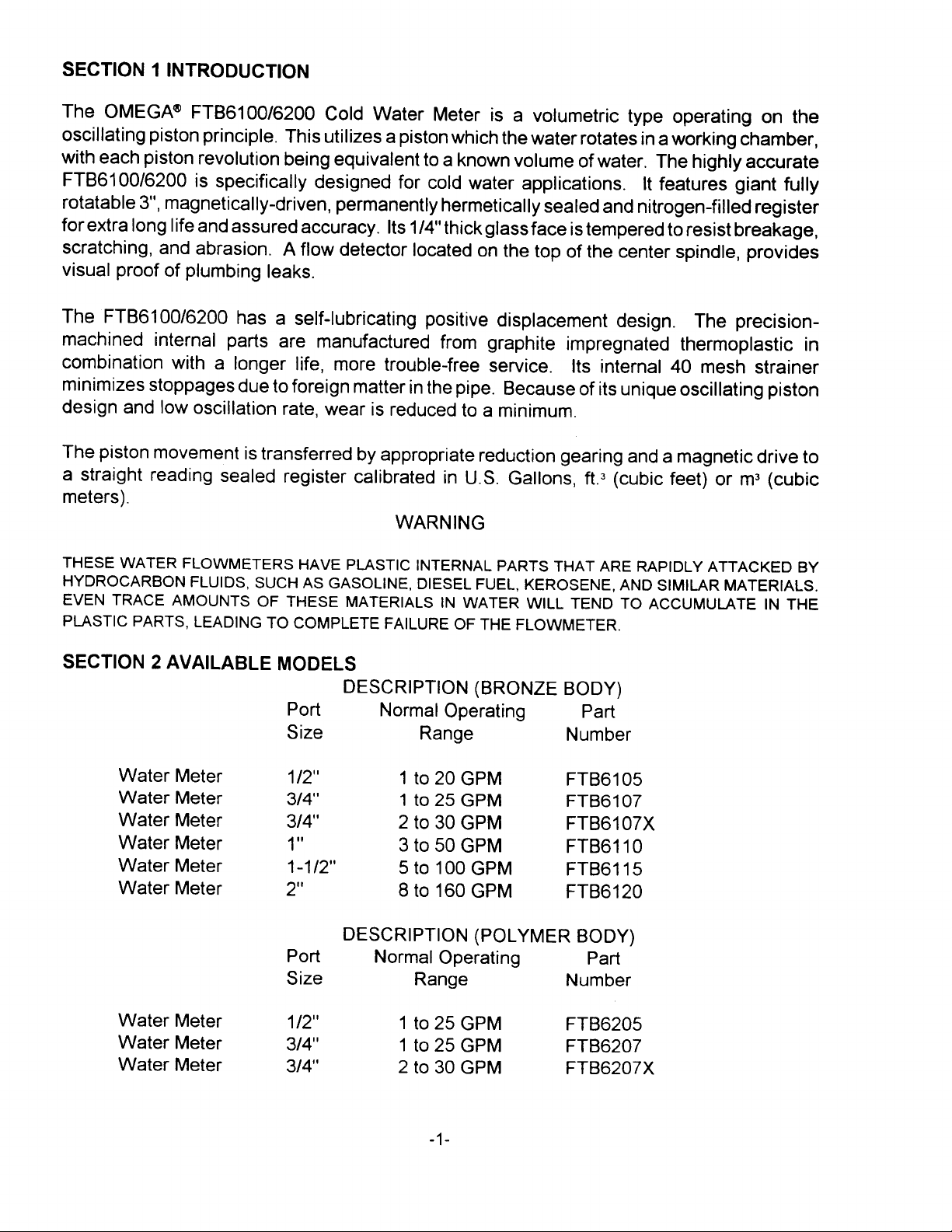
SECTION 1 INTRODUCTION
The OMEGA@
FTB6100/6200 Cold Water Meter is a volumetric type operating on the
oscillating piston principle. This utilizes a piston which the water rotates in a working chamber,
with each piston revolution being equivalent to a known volume of water. The highly accurate
FTB6100/6200 is specifically designed for cold water applications.
3”,
rotatable
for extra long life and assured accuracy. Its
magnetically-driven, permanently hermetically sealed and nitrogen-filled register
l/4”
thickglassface is tempered to resist breakage,
It features giant fully
scratching, and abrasion. A flow detector located on the top of the center spindle, provides
visual proof of plumbing leaks.
The
FTB6100/6200 has a self-lubricating positive displacement design. The
precision-
machined internal parts are manufactured from graphite impregnated thermoplastic in
combination with a longer life, more trouble-free service. Its internal 40 mesh strainer
minimizes stoppages due to foreign matter in the pipe.
Because of its unique oscillating piston
design and low oscillation rate, wear is reduced to a minimum.
The piston movement is transferred by appropriate reduction gearing and a magnetic drive to
m3
a straight reading sealed register calibrated in U.S. Gallons,
ft.”
(cubic feet) or
(cubic
meters).
WARNING
THESE WATER FLOWMETERS HAVE PLASTIC INTERNAL PARTS THAT ARE RAPIDLY ATTACKED BY
HYDROCARBON FLUIDS, SUCH AS GASOLINE, DIESEL FUEL, KEROSENE, AND SIMILAR MATERIALS.
EVEN TRACE AMOUNTS OF THESE MATERIALS IN WATER WILL TEND TO ACCUMULATE IN THE
PLASTIC PARTS, LEADING TO COMPLETE FAILURE OF THE FLOWMETER.
SECTION 2 AVAILABLE MODELS
Port
Size Range
Water
Water Meter
Meter
Water Meter
Water Meter
Water Meter
l/2”
314”
314”
”
1
l-l
12”
Water Meter 2”
Port
Size
Water Meter
Water Meter
Water Meter
l/2”
314”
314”
DESCRIPTION (BRONZE BODY)
Normal Operating
Part
Number
1to20
1 to 25 GPM
GPM
2 to 30 GPM
3to50 GPM
5to100GP M
8 to 160 GPM
FTBGI
FTB6107
FTBGI
FTBGI
FTB6115
FTB6120
DESCRIPTION (POLYMER BODY)
Normal Operating
Range
1 to 25 GPM
to
25 GPM
1
2 to 30 GPM
Part
Number
FTB6205
FTB6207
FTB6207X
05
07X
10
-l-
Page 4

SECTION 3 INSTALLATION
3.1 UNPACKING
Remove the Packing list and verify that you have received all equipment, including the
following (quantities in parentheses):
FTB6100 or FTB6200 Series Cold Water Meter (1)
Operator’s Manual (1)
If you have any questions about the shipment, please call the OMEGA Customer Service
Department. When you receive the shipment, inspect the container and equipment for signs
of damage. Note any evidence of rough handling in transit. Immediately report any damage
to the shipping agent,
NOTE
The carrier will not honor any claims unless all shipping material
is saved for inspection. After examining and removing contents, save
packing material and carton in the event reshipment is necessary.
3.2 INSTALLATION
The meter must be installed in a clean pipeline, free from any foreign materials. The dial must
be mounted face upwards, no more than
45” from the horizontal.
The meter must be inserted with the flow in the direction of the arrow molded, or cast, into the
meter body.
112”
Couplings are provided, which allow for connection with NPT threads in sizes
12”
The l-l
and 2” meters have NPT screwed ends or oval flanged ends.
through I”.
SECTION 4 START-UP PROCEDURE
The meter piston can be damaged if the meter
is
subjected to full flow conditions prior to
expelling all the air from the piping. Therefore, turn on the flow gradually.
-2-
Page 5

SECTION 5 SPECIFICATIONS
ACCURACY:
FLUID TEMPERATURE RANGE:
WETTED PARTS:
MAXIMUM PRESSURE DROP:
MAXIMUM PRESSURE:
MAXIMUM TOTAL
(MILLIONS OF GALLONS)
MODEL
FTB6105
FTBGI
07 1-25
FTBGI 07X
FTBGI
FTBGI
FTBGI
10
15
20
NORMAL
OPERATING
RANGE
I-20 GPM
GPM
2-30 GPM
3-50
GPM
5-100
GPM
8-160
GPM
MIN.
TEST
FLOW
GPM
0.25
0.25
0.50
0.75
1.5
2
+ 1-l 12% of reading at normal operating range
120”
to +
bronze or polyacetal body;
impregnated polystyrene,
F.
graphite-
molybdenum-
loaded and glass-filled nylon, barium
ferrite magnet and polyacetal internal
wetted parts, neoprene gaskets, polymer
strainer (stainless steel for 2” unit).
PSID
15
150
10 up to 1
LENGTH
OVERALL
(<____________
7.5
7.5
9
10.75
12.63
15.25
at 1 CSTK
PSIG
DIA.
INCHES
4.75
4.75
4.75
7.06
7.5
8.75
‘I;
100 for l-1
HEIGHT SHIPPING
OVERALL
____________>)
5.5
6.94
8.5
10.5
/2” and 2”
5
5
WEIGHT (PULSE/
LBS. GAL)
6
6
15
24
26
42
“-PS”
STDlOPT
100/200
100/200
66.6/l
33.2
24.6149.2
11.3122.6
5.6111
.I
FTB6205 0.25-25
FTB6207 0.25-25
FTB6207X
0.5-30
GPM
GPM
GPM
*minimum measurable with
0.25
0.25
0.50
7.5
7.5
9
4.82
4.82
5.03
+ 5% of reading accuracy
5
5
5.5
4
4
5
SECTION 6 OPTIONS
“-PS”
Add suffix
“-PT”
or
for pulse output. Register is no longer hermetically sealed with
pulse output, but is weatherproof. Pulse option adds 0.63 lb. to weight, and
for PS. Pulse option adds 2 Ibs. to weight and 2 ” height for PT.
Pulse Output Options:
12”
1”
1
6.1
“-PT”:
pulse/gallon for
pulser is a limit switch rated at 3A
“-PS”: Solid State requires 6-24 VDC, 3
6.2
or smaller:
@125
above.
VAC.
l
puise/lO gallon for
wire.
For pulse rate, see
l-1
and 2”. PT
PS
100/200
100/200
66.61133.2
2-314”
height
(pulse/gallon)
-3-
Page 6

SECTION 6 OPTIONS
6.1
To be wired in series. Refer to Figure
-PT OPTION
1.
This unit requires power from an external source.
WIRING DIAGRAM
N/O = Normally Open
N/C = Normally Closed
SOUKCE
-
PT Option
Figure 1.
PWEK
Wiring Diagram for
The transmitting element is a 3A limit switch, giving a closure rate as follows:
98”
314”
1”
l-1/2”
2”
6.2
-PS OPTION (SOLID STATE)*
1 Contact Per Gallon
1 Contact Per Gallon
1 Contact Per Gallon
1
Contact
1
Contact
Per10Gallons
Per10Gallons
3-wire system. Refer to Figure 2. The unit requires power from an external source, 6-24
VDC, NEMA 4.
Red -------
Black
White ------- Output
Figure 2. Wiring Diagram for New Solid State Pulser -PS Option
The transmitting element is
actuated to provide a
mA
(max) (3 wire).
50150
Contact Closures are:
SIZE
112”
5/8”
5/8”
5/8”
518”
314”
I”
Bronze
l-l
2” Bronze
Improved Brz
x
3/4”
Improved Brz
x
IQ”
Polymer
x
314”
Polymer
x
314”
x
/2” Bronze
BtzIPoly
_______
an open collector current sink
open/closed ratio. Supply Voltage: 6-24 VDC; Supply Current: 13.5
+ Positive Power Supply, 6-24 VDC
-
Negative Ground
(NPN)(20V
STANDARD
(Contacts/gallon) (Contacts/gallon)
115.2
115.2
100.0
100.0
66.6
24.6
11.3
5.6
mA
OPTIONAL
230.4
230.4
200.0
200.0
133.2
49.2
22.6
11.1
max.) magnetically
??
All previous hi-resolution pulsers (PS-type) were dry contact reed switches
-4-
(3W)
and were wired in series.
Page 7

BRONZE
BODY
POLYMER BODY
[
Meter
Size
Dimensions and Net Weights
;
A
‘12.x Q’
V.’ x s/a-
j
j
Dmenslons
)
C 0 i
1
1
SEE
When used with couplings, add to dimension (inches) A:
lW62,qhr
-I
/)
(Ibs
1
I
I
1
Meter
52%
/
‘I,- x 5,; 1
Bronze Body Polymer Body
7/a
4
Ata
5
i/a
5
3/a
5
PAGEj
PAGEj
Size
5/a
518
314
(tnches)
)
D E
SEti
112
x
x
314
314
x
1
7
7
When used with pulser, add to dimension B:
Pulsers model PT
Pulsers model PS
??
3/16
.
2
. . . .
314
.
2
. . .
*Dotted line shows position of PT
Dlmenslons
/‘BBC
-s+TjT
;‘,_I
4
pulsers
and Net Weights
(Inches)--Dmenslons
D---zy-
B
,
314
5
5
DiE
9’11)
Wegri7
(Ibs
3’1,
!
:
:
Cover is deleted when meter is provided with a pulser.
NOTE:
All above dimensions are inch measurements.
DIMENSIONS
COLD WATER METERS
FTB 6105
FTB 6107
FTB 6107X
FTB 6110
-5-
FTB 6205
FTB 6207
6207X
f=TB
Page 8

- 0
View on direction of arrow
“A” showing flow arrow and
body markings.
Connections are oval flanged o
CENTER
NPT Female.
LINE TO BOTTOM DIAMETER HEIGHT
(C) (D)
l/8”
2
1
314”
8
8
112”
314”
Meters are designed for Cold Water Service up to 120°F.
At 150 PSIG. Strainers with a 40 Mesh Screen should be used if foreign matter is
present.
NOTE:
Dotted line shows position of PT or PS Pulser.
Cover is deleted when meter is provided with a pulser.
12
14
(E)
l/4”
l/4”
10
12
PT
7/16”
5116”
WlPULSER SHIPPINGW/LID UP HEIGHT
PS
l/4”
11
13”
 Loading...