

Page 1

Page 2

2
Page 3
GENERAL DESCRIPTION
The Omega FTB-1400 Series turbine flow meter is designed with
wear resistant moving parts to provide trouble-free operation and
long service life. The turbine repair kit allows easy field repair of
a damaged flow meter, rather than replacing the entire flow
meter. Repair parts are constructed of stainless steel alloy and
tungsten carbide.
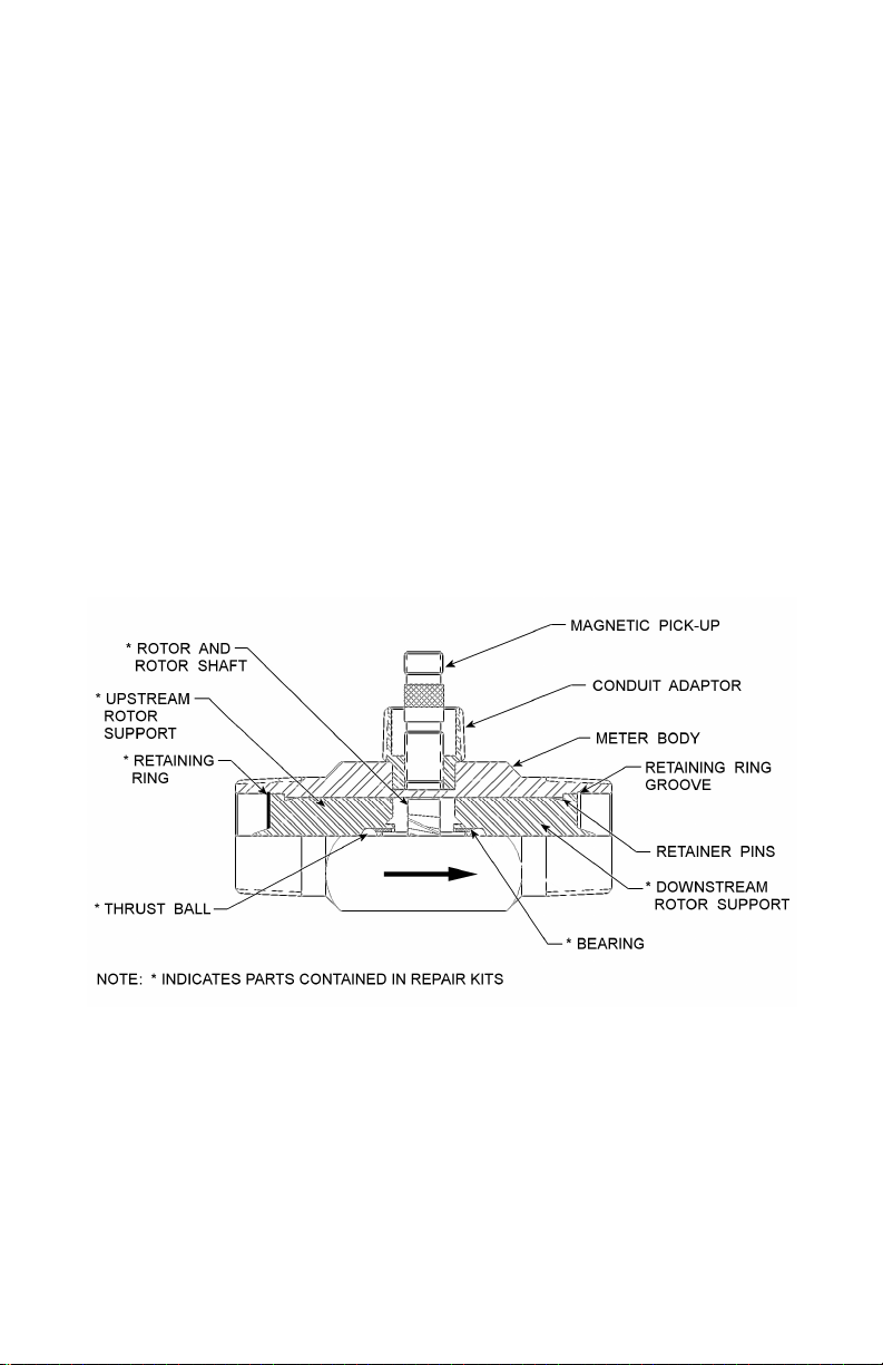
Fluid moving through the turbine flow meter causes the rotor to
turn at a speed proportional to the flow rate. The rotor blade cuts
the magnetic field of the magnetic pick-up, which in turn
generates a frequency output signal that is directly proportional to
the speed. The signal is used to represent flow rate and/or
totalization of fluid passing through the turbine flow meter. See
Figure 1 for typical turbine meter assembly.
FIGURE 1
Each turbine meter repair kit is factory calibrated to ensure
accuracy throughout the entire flow range. Each kit is complete
and includes a new K-factor, which is the calibrated number of
pulses generated by each gallon of liquid. This K-factor will be
used to recalibrate the monitor, or other electronics, to provide
accurate output data.
3
Page 4

PART INFORMATION
Repair Kit
Part Number
FTB-1400A-RK ⅜" FTB-1411, FTB-1421
FTB-1400B-RK ½" FTB-1412, FTB-1422
FTB-1400C-RK ¾" FTB-1413, FTB-1423
FTB-1400D-RK ⅞" FTB-1424
FTB-1400E-RK 1" FTB-1425
FTB-1400F-RK 1-½" FTB-1431
FTB-1400G-RK 2" Low FTB-1441
FTB-1400-MP
Flow Meter
Size
Std. Magnetic
Pick-up
Repair Kit Fits
Meter Model Number
All Meter Sizes
4
Page 5

TURBINE METER REMOVAL
WARNING: High-pressure leaks are dangerous and cause
personal injury. Make sure that fluid flow has been shut off
and pressure in the line released before attempting to remove
the meter.
DISASSEMBLY
Refer to Figure 2 on page 7 for relative positions of repair kit
components.
1. Remove the magnetic pick-up from the meter body to avoid
damage during repair.
2. Remove the retaining ring from one end of the meter.
3. Remove the rotor support from the body. If the rotor
support is jammed in the body, use a pair of pliers or vicegrips to break the rotor support free.
4. The rotor may also be removed at this time. Remove the
retaining ring from the opposite side of the meter.
5. Remove the second rotor support.
INSTALLATION OF NEW KIT
IMPORTANT: Before reassembly, note that an arrow is cast or
engraved on each component*. The arrow indicates the direction
of flow. The meter must be reassembled with arrowheads pointed
in the direction of fluid flow. The arrows are to be oriented in the
up position on both rotor supports. The magnetic pick-up side of
the body signifies the up position. This is the position that was
used to calibrate the repair kit and this is the position that is to be
used to ensure meter accuracy.
5
Page 6

Figure 2 on page 7 shows the proper alignment and orientation of
the repair kits.
* Fractional size rotors (⅜", ½", ¾" & ⅞") do not contain a cast
or engraved arrow, however Omega provides a colored cap on the
downstream side of the rotor shaft to indicate flow direction.
Remove this cap before assembly, noting flow direction.
1. Install one of the rotor supports into the body bore, noting
the orientation of the arrow.
2. Secure a retaining ring in the groove provided. Be sure
that retaining rings are completely installed in each groove.
3. Insert the rotor and second rotor support in the opposite
side of the body, noting the orientation of the arrow.
4. Secure the second retaining ring in the opposite groove, as
noted in Step 2 above.
5. Check the meter by blowing air through the assembly. If
the rotor does not turn freely, the meter should be
disassembled and checked for anything that would obstruct
movement of the rotor.
CAUTION: Excess air pressure may damage the rotor and
bearings by over spinning.
6. Install the magnetic pick-up.
Note: At this time electronics will need recalibration. Refer
to the proper installation and operation manual. If there are
any questions on recalibration, contact Omega.
6
Page 7

FIGURE 2
for Turbine Meters
Relative Positions of Internal Components
7
Page 8

NOTES
8
Page 9

NOTES
9
Page 10

NOTES
10
Page 11

11
Page 12

12
 Loading...