

Page 1
omega.com
e-mail: info@omega.com
For latest product manuals:
omegamanual.info
User’s Guide
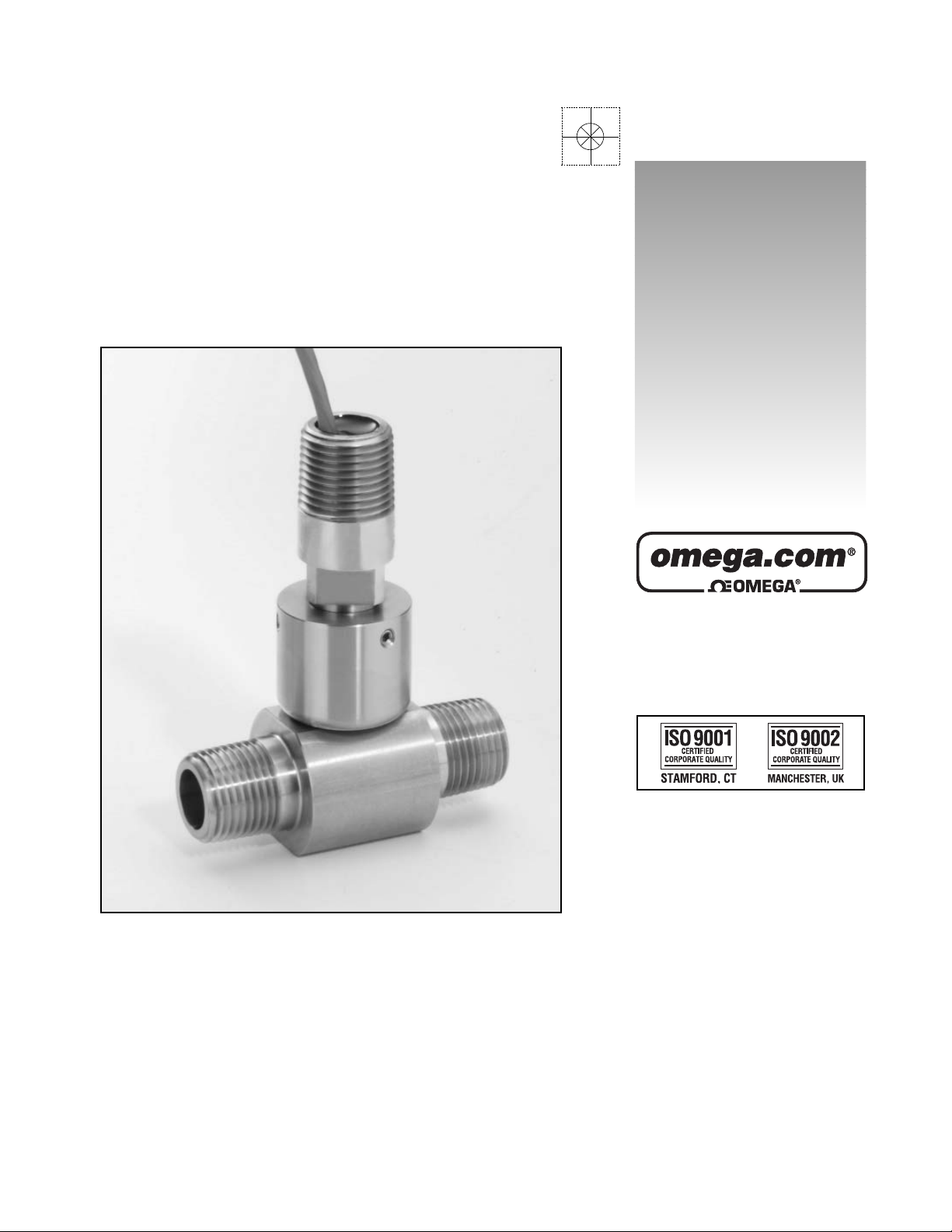
FTB-1300 Series
Turbine Flow Meters
Shop online at
Page 2

Servicing North America:
U.S.A.: One Omega Drive, Box 4047
ISO 9001 Certified Stamford, CT 06907-0047
Tel: (203) 359-1660
FAX: (203) 359-7700
e-mail: info@omega.com
Canada: 976 Bergar
Laval (Quebec) H7L 5A1, Canada
Tel: (514) 856-6928
FAX: (514) 856-6886
e-mail: info@omega.ca
For immediate technical or application assistance:
U.S.A. and Canada: Sales Service: 1-800-826-6342/1-800-TC-OMEGA
®
Customer Service: 1-800-622-2378/1-800-622-BEST
®
Engineering Service: 1-800-872-9436/1-800-USA-WHEN
®
Mexico: En Espan˜ ol: (001) 203-359-7803
e-mail: espanol@omega.com
FAX: (001) 203-359-7807
info@omega.com.mx
Servicing Europe:
Czech Republic: Frystatska 184, 733 01 Karvina´, Czech Republic
Tel: +420 (0)59 6311899
FAX: +420 (0)59 6311114
Toll Free: 0800-1-66342
e-mail: info@omegashop.cz
Germany/Austria: Daimlerstrasse 26, D-75392 Deckenpfronn, Germany
Tel: +49 (0)7056 9398-0
FAX: +49 (0)7056 9398-29
Toll Free in Germany: 0800 639 7678
e-mail: info@omega.de
United Kingdom: One Omega Drive, River Bend Technology Centre
ISO 9002 Certified Northbank, Irlam, Manchester
M44 5BD United Kingdom
Tel: +44 (0)161 777 6611
FAX: +44 (0)161 777 6622
Toll Free in United Kingdom: 0800-488-488
e-mail: sales@omega.co.uk
OMEGAnet®Online Service Internet e-mail
omega.com info@omega.com
It is the policy of OMEGA Engineering, Inc. to comply with all worldwide safety and EMC/EMI
regulations that apply. OMEGA is constantly pursuing certification of its products to the European New
Approach Directives. OMEGA will add the CE mark to every appropriate device upon certification.
The information contained in this document is believed to be correct, but OMEGA accepts no liability for any
errors it contains, and reserves the right to alter specifications without notice.
WARNING: These products are not designed for use in, and should not be used for, human applications.
Page 3
FTB-1300 Series - Turbine Flow Meters
General Description . . . . . . . . . . . . . . . . . . . . . . . . . . . . . . . . . . . . . . . . . . . . .2
Installation Instructions . . . . . . . . . . . . . . . . . . . . . . . . . . . . . . . . . . . . . . . . . . .3
Operational Start Up . . . . . . . . . . . . . . . . . . . . . . . . . . . . . . . . . . . . . . . . . . . . .4
Trouble Shooting Guide . . . . . . . . . . . . . . . . . . . . . . . . . . . . . . . . . . . . . . . . . .5
Repair Kit Information . . . . . . . . . . . . . . . . . . . . . . . . . . . . . . . . . . . . . . . . . . . .6
Installation and Technical Data Guide . . . . . . . . . . . . . . . . . . . . . . . . . . . . . .7-8
FTB-1301 through FTB-1308
Installation and Technical Data Guide . . . . . . . . . . . . . . . . . . . . . . . . . . . . .9-10
FTB-1311 through FTB-1318
Page 4

Page 5
FTB-1300 Series Turbine Flow Meter
General Description:
The FTB-1300 series of turbine flow
meters is designed with a wear resistant
rotor assembly to provide trouble free
operation and a long service life. Fluid
moving through the flow meter causes the
rotor to turn at a speed proportional to the
flow rate, and as the rotor blades cut
through the magnetic field of the pickup,
an electronic pulse is generated.
The pulse train is used to represent the
actual flow or total amount of fluid passing
through the flow meter. The number of
electronic pulses generated per unit
volume is known as a K-factor. The value
is constant over each flow meter's
operating range, and is unique to each
meter.
Operating Limitations of the FTB-1300 Series Turbine Flow Meters
:
1) Pressure - 5,000 PSI max
WARNING: Pressure in excess of allowable rating may cause the housing to burst and cause
serious personal injury.
2) Corrosion - The internal parts of the meter are constructed of stainless steel (316L & 1.4122) and
carbide with nickel binder. Be sure that the operating fluid is compatible with these materials.
Incompatible fluids will deteriorate internal parts, and cause the meter to read inaccurately.
3) Pulsation - Severe pulsation will affect accuracy, and shorten the life of your meter.
4) Vibration & Shock - Severe mechanical vibration may decrease service life of the meter.
5) Filtration - A strainer should be installed upstream of the meter if small particles are present (see
Table 1 for filtration requirements)
-1-
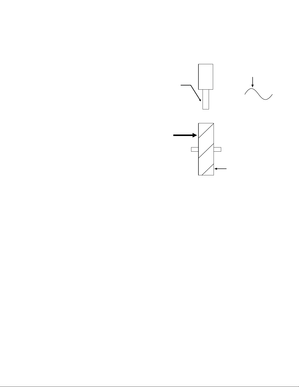
OUTPUT SIGNAL
MAGNETIC PICKUP
FLUID FLOW
ROTOR
Page 6

Installation Instructions:
Before installation, the flow meter should be checked internally for foreign material and to ensure that
the rotor spins freely. Fluid lines should also be cleared of all debris.
Warning: Make sure that fluid flow has been shut off and pressure in the line released before
attempting to install the meter in an existing system.
The flow meter must be installed with the flow indication arrow, etched on the exterior of the meter body,
pointing in the correct direction of flow. The preferred mounting orientation is to have the meter installed
in horizontal piping, with the pickup facing upward. However, the meter will function in any position.
The liquid that is to be measured must be free from any large particles that may obstruct rotation of the
rotor. If particles are present, a mesh strainer should be installed upstream before operation of the flow
meter. (See Table 1)
Table 1
Note: Select appropriate strainer for your turbine model by your turbine part number.
The preferred plumbing setup is one containing a bypass line that allows meter inspection and repair
without interrupting flow. If a bypass line is not utilized, it is important that all control valves be located
downstream of the flow meter.
It is recommended that a minimum length, equal to ten (10) pipe diameters of straight pipe be installed
on the upstream side and five (5) diameters on the downstream side of the flow meter. Otherwise meter
accuracy may be affected. Piping should be the same size as the meter bore or the thread port size.
Do not locate the flow meter or the connection cable close to electric motors, transformers, sparking
devices, high voltage lines or place connecting cable in conduit with wire furnishing power for such
devices. These devices can induce false signals in the flow meter coil or cable, causing the meter to read
inaccurately.
New Model Number Strainer Mesh
FTB-1301 & FTB-1311 140 x 140
FTB-1302 & FTB-1312 140 x 140
FTB-1303 & FTB-1313 140 x 140
FTB-1304 & FTB-1314 50 x 50
FTB-1305 & FTB-1315 50 x 50
FTB-1306 & FTB-1316 50 x 50
FTB-1307 & FTB-1317 50 x 50
FTB-1308 & FTB-1318 50 x 50
-2-
Page 7

Operational Start Up:
The following practices should be observed when installing and starting the meter.
1) After meter installation, close the isolation valves, and open the bypass valve. Flow liquid through the
bypass valve for sufficient time to eliminate any air or gas in the flow line.
Caution: Damage can be caused by striking an empty meter with a high velocity flow
stream.
2) Open upstream isolating to eliminate hydraulic shock while charging the meter with the liquid. Open
the valve to full open.
3) Open downstream isolating valve to permit meter to operate.
4) Close the bypass valve to a full closed position.
5) Adjust the downstream valve to provide the required flow rate through the meter.
NOTE: the downstream valve may be used as a control valve.
If problems arise with the flow meter, consult the Trouble Shooting Guide (Appendix A). If further problems arise, consult the factory. Turbine meter repair kits are also available. See appendix B & C.
-3-
FLUID FLOW
5 PIPE DIAMETERS
ISOLATING VALVE &
FLOW RATE CONTROL VALVE
FLUID FLOW
TURBINE FLOW METER
10 PIPE DIAMETERS
ISOLATING VALVE
BYPASS VALVE
PICKUP OR ELECTRONIC
FLOW MONITOR
FLUID FLOW
5 PIPE DIAMETERS
ISOLATING VALVE &
FLOW RATE CONTROL VALVE
FLUID FLOW
TURBINE FLOW METER
10 PIPE DIAMETERS
ISOLATING VALVE
PICKUP OR ELECTRONIC
FLOW MONITOR
Page 8

Trouble Shooting Guide:
Trouble
Meter indicates higher than
actual flow rate
Meter indicates lower than
actual flow rate
Erratic system indication, meter
alone works well (remote
monitor application only)
Indicator shows flow when shut
off
No flow indication. Full or partial open position.
Erratic indication at low flow,
good indication at high flow.
No flow indication.
System works perfect, except
indicates lower flow over entire
range.
Meter indicating high flow,
upstream piping at meter
smaller than meter bore.
Opposite affects as above.
Possible Cause
Cavitation
Debris on rotor support
Build up of foreign material on
the meter bore
Gas in liquid
Debris on rotor
Worn bearing
Viscosity higher than calibrated
Ground loop in shielding
Mechanical vibration causes
rotor to oscillate without turning
Fluid shock, full flow into dry
meter or impact caused bearing
separation or broken rotor shaft.
Rotor has foreign material
wrapped around it.
Faulty pickup.
Bypass flow, leak.
Fluid jet impingement on rotor.
Viscosity lower than calibrated.
Remedy
Increase back pressure
Remove debris
Clean meter
Install gas eliminator ahead of
meter
Clean meter and add filter
Clean meter, add filter and
replace bearing
Recalibrate monitor
(Appendix A)
Ground shield one place only.
Look for internal electronic
instrument ground. Reroute
cables away from electrical
noise.
Isolate meter
Rebuild meter with repair kit
and recalibrate monitor. Move
to location where meter is full
on start-up or add downstream
flow control valve.
Clean meter and add filter.
Replace pickup.
Repair bypass valves, or faulty
solenoid valves.
Change piping.
Change temperature, change
fluid or recalibrate meter.
-4-
Page 9

Repair Kit Information
Line Sizes 1/8" up to 2"
Caution: Always reassemble rotor supports. Rotor and meter body are all marked with
flow arrows, which must all point in the same direction.
Flow meter Repair kit fits Repair kit
size meter model # part number
1/8" FTB-1301 & FTB-1311 FTB-131-RK
¼" FTB-1302 & FTB-1312 FTB-132-RK
3/8" FTB-1303 & FTB-1313 FTB-133-RK
½" FTB-1304 & FTB-1314 FTB-134-RK
5/8" FTB-1305 & FTB-1315 FTB-135-RK
7/8" FTB-1306 & FTB-1316 FTB-136-RK
1-½" FTB-1307 & FTB-1317 FTB-137-RK
2" FTB-1308 & FTB-1318 FTB-138-RK
DOWNSTREAM ROTOR SUPPORTUPSTREAM ROTOR SUPPORT
SWIVEL FITTING
SENSOR
METER BODY
THRUST BALLS (2) BEARINGS (2)
ROTOR & SHAFT
-5-
Page 10

FTB-1301 to FTB-1308 Hall Effect Pickup
Installation and Technical Data Guide
Description:
The FTB-1301 - 1308 Hall Effect sensors are compatible with Positive Displacement gear flow meters
and turbine flow meters. The sensor detects the rotation of the flow meter’s gears and emits a frequency signal proportional to flow. The output signal is a square wave pulse which has a duty cycle of
approximately 50%.
Signal outputs are protected with a self-resetting fuse. This fuse has a 50mA nominal trip point. When
a trip occurs, turn off power to the sensor and remove output load to reset fuse.
Installation:
• Ensure that the flowmeter sensor cavity is free of debris prior to installing pickup
• Swivel fitting is required for sensor mounting. Note: In order to recieve correct swivel fitting with your
sensor - you must specify meter part number when ordering
• 4 Steps to properly install sensor:
1- Securely fasten swivel fitting on flow meter
2- Turn set screws counter clockwise until they are not visible inside the swivel fitting
3- Install sensor into swivel fitting until sensor bottoms out in the sensor hole
4- Tighten set screws by turning clockwise
NOTE: DO NOT OVER TIGHTEN SET SCREWS OR SENSOR DAMAGE WILL OCCUR!
NOTE: WIRING SHOULD BE INSTALLED BY A QUALIFIED INSTRUMENTATION TECHNICIAN
MAG-PB W
ire Color
NC Green
Output White
Ground Black
Supply Red
Wiring Color Code:
-6-
Page 11

FTB-1301 to FTB-1308 Hall Effect Pickup
Installation and Technical Data Guide
MAG-PB Sourcing Output Circuit
• Signal output square wave :
V
high
= Supply -1V @ no output load
V
low
= 0.1V
• Max sourced output voltage: Supply -0.5V
• Max current sourcing capabilities: 50mA
Supply Voltage: +10 to 28 Volt DC
Supply Current: 8 mA @ 12 VDC, 12mA @ 24 VDC
Duty Signal: 50% ± 15%
Minimum Signal: 0.5 Hz
Frequency Output: Flow dependent, up to 2,000 Hz
Driving Capacity: 50 mA Max resistive load
Output Impedance: ~ 40 Ohm - analog switch and self-resetting fuse
Temperature Range: -40° F to 185° F (-40° C to 85° C)
T
echnical Data:
-7-
A
nalog
Switch
~40 Ohm
SUPPLY
OUTPUT
GROUND
Page 12

FTB-1311 to FTB-1318 Analog Output Pickup
Installation and Technical Data Guide
Description:
The FTB-1311-1318 are microprocessor based, meter mounted, analog output sensors. Each unit has
a sensor, amplifier and converter module built into an Ex housing. The transmitter is designed to handle frequencies up to 5,000 Hz. The operational frequency range is user defined via four BCD rotary
switches, where the high flow rate in frequency is set to 20 mA and the output signal is automatically
scaled. End connection is a 3-pin male connector.
NOTE: This is a 3 wire hookup and is not suitable for a 2 wire installation.
Technical Specifications:
Supply Voltage: 10-30 VDC
Supply Current: 60 mA max
Signal Output: 4-20mA or
Maximum Load
Impedance (Vcc/0.02): 275 ohm (for mA out)
Temperature Range: 0-185° F
Jumper Settings:
J1 AB: Analog Output
BC: Frequency Output
J2 AB: Housing Ground
CB: Signal ground
Response Time: 1/F + 25 msec
Frequency Input: 5 KHz max
Diagnostics: A glowing LED indicates the
unit is working. The LED will
blink to show an active
frequency.
-8-
"S" VERSION
CONNECTOR
(A) +10-30 VDC
C
A
(B) COMMON
B
(C) SIGNAL OUT
+10-30 VDC
COMMON
SIGNAL OUT
"E" VERSION
PIGTAIL LEADS
RED
BLACK
WHITE
S1 S2 S3 S4
1
1
0
2
9
3
8
4
7
5
6
J1
ABC
OUT
1
0
0
2
2
9
9
3
3
8
8
4
4
7
7
5
5
6
6
CBA
J2
1
0
2
9
3
8
4
7
5
6
Page 13

Scaling Analog Output:
On the front panel there are four rotary switches which are
adjustable with a small screwdriver. It is not necessary to
power the unit down to change the settings. The switches are
read from left to right in order of decreasing value as shown in
the figure to the right.
If the maximum frequency is known at which the resulting output should be 20mA, set the switches to
this frequency. The output will automatically scale itself. If the maximum frequency is not known, the correct
switch settings can be determined in 2 ways.
The following equation can be used to determine what the switch setting should be for any particular meter and
flow rate.
Switch Setting =
Where: K Factor is the flow meter scaling factor in pulses / volume (found on calibration sheet)
Max. Flow Rate is the flow rate at which the analog output should be at it's max.
Note: K-Factor and Max flow rate MUST have same units, ie: gallon/GPM, liter/LPM
60 is the scaling factor when max. flow rate is in volume/minute. Use 3600 for volume/hour
Ex: K Factor = 89,100 pulses/gallon (for a FTB-1301), Max flow rate = 0.2 GPM
Switch Setting = = 297
If the numerical flow rate is not known, the unit can be calibrated in systems with the following:
1) Adjust system flow to the rate at which analog output should read 20 mA.
2) Set scaling switches to a value known to be above the maximum frequency (ex. 9, 49, 799, 2999) if unsure,
use 4999
3) If S1 is 0, go to step 4. Decrease S1 until output shows 20 mA. Then increase its setting by one unless value
is 4, in which case value should remain 4. If the switch value is 0 and the output is below 20 mA, leave switch
at 0 and go to next switch.
4) If S2 is 0, go to step 5. Decrease S2 until output shows 20 mA. Then increase its setting by one unless value
is 9, in which case value should remain 9. If the switch value is 0 and the output is below 20 mA, leave switch
at 0 and go to next switch.
5) If S3 is 0, go to step 6. Decrease S3 until output shows 20 mA. Then increase its setting by one unless value
is 9, in which case value should remain 9. If the switch value is 0 and the output is below 20 mA, leave switch
at 0 and go to next switch.
6) Decrease S4 until output shows 20 mA and leave setting. DO NOT increase this setting by one. The switches
are now set at the frequency which will result in a 20 mA output.
When setting switches in step 1, try to use numbers ending in 9 for example: 9, 39, 299 and 2999. Any switch
setting above 5000 Hz is read as 4999 Hz.
Example: Actual maximum input frequency is 538 Hz. Switches are set to 0999 Hz, a value known to be above
actual maximum input frequency. The output shows 12.64 mA.
Starting with the switch of highest order, in this case S2 since S1 is 0, its value is decreased until the output
shows 20 mA (S2 shows 4). The switch is then increased by 1 (S2 is set to 5). S3 is then decreased until the
output shows 20 mA (S3 shows 2). The switch is then increased by 1 (S3 is set to 3). Finally, S4 is decreased
until the output shows 20 mA and left as such (S4 set at 8) the switches are now set to 538 Hz, the frequency
which will cause maximum output current / voltage.
K Factor * Max Flow Rate
60
89,100 * 0.2
60
-9-
x1000 x100 x10 x1
1
0
2
9
3
8
4
7
5
6
1
0
2
9
3
8
4
7
5
6
1
0
2
9
3
8
4
7
5
6
S1 S2 S3 S4
1
0
2
9
3
8
4
7
5
6
Page 14

-10-
Page 15

WARRANTY/ DISCLAIMER
OMEGA ENGINEERING, INC. warrants this unit to be free of defects in materials and workmanship for a period of 13
months from date of purchase. OMEGA’s WARRANTY adds an additional one (1) month grace period to the normal
one (1) year product warranty to cover handling and shipping time. This ensures that OMEGA’s customers receive
maximum coverage on each product.
If the unit malfunctions, it must be returned to the factory for evaluation. OMEGA’s Customer Service Department will
issue an Authorized Return (AR) number immediately upon phone or written request. Upon examination by OMEGA, if
the unit is found to be defective, it will be repaired or replaced at no charge. OMEGA’s WARRANTY does not apply to
defects resulting from any action of the purchaser, including but not limited to mishandling, improper interfacing,
operation outside of design limits, improper repair, or unauthorized modification. This WARRANTY is VOID if the unit
shows evidence of having been tampered with or shows evidence of having been damaged as a result of excessive
corrosion; or current, heat, moisture or vibration; improper specification; misapplication; misuse or other operating
conditions outside of OMEGA’s control. Components in which wear is not warranted, include but are not limited to
contact points, fuses, and triacs.
OMEGA is pleased to offer suggestions on the use of its various products. However,
OMEGA neither assumes responsibility for any omissions or errors nor assumes liability for any damages
that result from the use of its products in accordance with information provided by OMEGA, either
verbal or written. OMEGA warrants only that the parts manufactured by the company will be as
specified and free of defects. OMEGA MAKES NO OTHER WARRANTIES OR REPRESENTATIONS OF ANY
KIND WHATSOEVER, EXPRESSED OR IMPLIED, EXCEPT THAT OF TITLE, AND ALL IMPLIED WARRANTIES
INCLUDING ANY WARRANTY OF MERCHANTABILITY AND FITNESS FOR A PARTICULAR PURPOSE ARE
HEREBY DISCLAIMED. LIMITATION OF LIABILITY: The remedies of purchaser set forth herein are
exclusive, and the total liability of OMEGA with respect to this order, whether based on contract,
warranty, negligence, indemnification, strict liability or otherwise, shall not exceed the purchase price of
the component upon which liability is based. In no event shall OMEGA be liable for consequential,
incidental or special damages.
CONDITIONS: Equipment sold by OMEGA is not intended to be used, nor shall it be used: (1) as a “Basic Component”
under 10 CFR 21 (NRC), used in or with any nuclear installation or activity; or (2) in medical applications or used on
humans. Should any Product(s) be used in or with any nuclear installation or activity, medical application, used on
humans, or misused in any way, OMEGA assumes no responsibility as set forth in our basic WARRANTY/ DISCLAIMER
language, and, additionally, purchaser will indemnify OMEGA and hold OMEGA harmless from any liability or damage
whatsoever arising out of the use of the Product(s) in such a manner.
RETURN REQUESTS/INQUIRIES
Direct all warranty and repair requests/inquiries to the OMEGA Customer Service Department. BEFORE RETURNING
ANY PRODUCT(S) TO OMEGA, PURCHASER MUST OBTAIN AN AUTHORIZED RETURN (AR) NUMBER FROM
OMEGA’S CUSTOMER SERVICE DEPARTMENT (IN ORDER TO AVOID PROCESSING DELAYS). The assigned AR number
should then be marked on the outside of the return package and on any correspondence.
The purchaser is responsible for shipping charges, freight, insurance and proper packaging to prevent breakage in
transit.
FOR W
ARRANTY RETURNS, please have the following
information available BEFORE contacting OMEGA:
1. Purchase Order number under which the product
was PURCHASED,
2. Model and serial number of the product under
warranty, and
3. Repair instructions and/or specific problems
relative to the product.
OMEGA’s policy is to make running changes, not model changes, whenever an improvement is possible.
This affords our customers the latest in technology and engineering.
OMEGA is a registered trademark of OMEGA ENGINEERING, INC.
© Copyright 2007 OMEGA ENGINEERING, INC. All rights reserved. This document may not be copied, photocopied,
reproduced, translated, or reduced to any electronic medium or machine-readable form, in whole or in part, without the
prior written consent of OMEGA ENGINEERING, INC.
FOR NON-WARRANTY REPAIRS,
consult OMEGA for
current repair charges. Have the following information
available BEFORE contacting OMEGA:
1. Purchase Order number to cover the COST of the
repair,
2. Model and serial number of the product, and
3. Repair instructions and/or specific problems
relative to the product.
Page 16

Where Do I Find Everything I Need for
Process Measurement and Control?
OMEGA…Of Course!
Shop online at omega.com
TEMPERATURE
䡺⻬
Thermocouple, RTD & Thermistor Probes, Connectors, Panels & Assemblies
䡺⻬
Wire: Thermocouple, RTD & Thermistor
䡺⻬
Calibrators & Ice Point References
䡺⻬
Recorders, Controllers & Process Monitors
䡺⻬
Infrared Pyrometers
PRESSURE, STRAIN AND FORCE
䡺⻬
Transducers & Strain Gages
䡺⻬
Load Cells & Pressure Gages
䡺⻬
Displacement Transducers
䡺⻬
Instrumentation & Accessories
FLOW/LEVEL
䡺⻬
Rotameters, Gas Mass Flowmeters & Flow Computers
䡺⻬
Air Velocity Indicators
䡺⻬
Turbine/Paddlewheel Systems
䡺⻬
Totalizers & Batch Controllers
pH/CONDUCTIVITY
䡺
⻬
pH Electrodes, Testers & Accessories
䡺⻬
Benchtop/Laboratory Meters
䡺⻬
Controllers, Calibrators, Simulators & Pumps
䡺⻬
Industrial pH & Conductivity Equipment
DATA ACQUISITION
䡺⻬
Data Acquisition & Engineering Software
䡺⻬
Communications-Based Acquisition Systems
䡺⻬
Plug-in Cards for Apple, IBM & Compatibles
䡺⻬
Datalogging Systems
䡺⻬
Recorders, Printers & Plotters
HEATERS
䡺⻬
Heating Cable
䡺⻬
Cartridge & Strip Heaters
䡺⻬
Immersion & Band Heaters
䡺⻬
Flexible Heaters
䡺⻬
Laboratory Heaters
ENVIRONMENTAL
MONITORING AND CONTROL
䡺⻬
Metering & Control Instrumentation
䡺⻬
Refractometers
䡺⻬
Pumps & Tubing
䡺⻬
Air, Soil & Water Monitors
䡺⻬
Industrial Water & Wastewater Treatment
䡺⻬
pH, Conductivity & Dissolved Oxygen Instruments
M-4638/0408
 Loading...