

Page 1
installation manual
®
http://www.omega.com
e-mail: info@omega.com
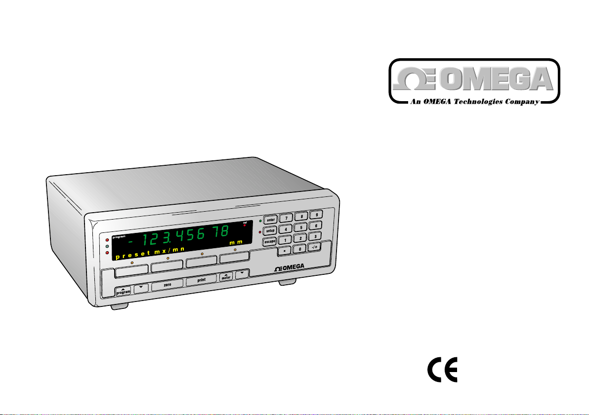
digital
benchtop
meter
model
no. DR601
Page 2
OMEGAnet®On-Line Service Internet e-mail
http://www.omega.com info@omega.com
Servicing North America:
USA:
ISO 9001 Certified
One Omega Drive, Box 4047
Stamford, CT 06907-0047
Tel: (203) 359-1660 FAX: (203) 359-7700
e-mail: info@omega.com
Canada: 976 Bergar
Laval (Quebec) H7L 5A1
Tel: (514) 856-6928 FAX: (514) 856-6886
e-mail: info@omega.ca
For immediate technical or application assistance:
USA and Canada:
Sales Service: 1-800-826-6342 / 1-800-TC-OMEGA
Customer Service: 1-800-622-2378 / 1-800-622-BEST
Engineering Service: 1-800-872-9436 / 1-800-USA-
SM
WHEN
TELEX: 996404 EASYLINK: 62968934 CABLE: OMEGA
SM
SM
Benelux:
Czech Republic: ul. Rude armady 1868, 733 01 Karvina-Hranice
France: 9, rue Denis Papin, 78190 Trappes
Germany/Austria: Daimlerstrasse 26, D-75392 Deckenpfronn, Germany
Mexico and
Latin America: Tel: (95) 800-826-6342 FAX: (95) 203-359-7807
En Espan ol: (95) 203-359-7803
e-mail: espanol@omega.com
It is the policy of OMEGA to comply with all worldwide safety and EMC/EMI regulations that apply. OMEGA is constantly pursuing certification of its products to the European
New Approach Directives. OMEGA will add the CE mark to every appropriate device upon certification.
The information contained in this document is believed to be correct, but OMEGA Engineering, Inc. accepts
no liability for any errors it contains, and reserves the right to alter specifications without notice.
WARNING: These products are not designed for use in, and should not be used for, patient-connected applications.
United Kingdom: One Omega Drive, River Bend Technology Centre
ISO 9002 Certified Northbank, Irlam, Manchester
Servicing Europe:
Postbus 8034, 1180 LA Amstelveen, The Netherlands
Tel: (31) 20 6418405 FAX: (31) 20 6434643
Toll Free in Benelux: 0800 0993344
e-mail: nl@omega.com
Tel: 420 (69) 6311899 FAX: 420 (69) 6311114
Toll Free: 0800-1-66342
e-mail: czech@omega.com
Tel: (33) 130-621-400 FAX: (33) 130-699-120
Toll Free in France: 0800-4-06342
e-mail: france@omega.com
Tel: 49 (07056) 3017 FAX: 49 (07056) 8540
Toll Free in Germany: 0130 11 21 66
e-mail: info@omega.de
M44 5EX, England
Tel: 44 (161) 777-6611 FAX: 44 (161) 777-6622
Toll Free in the United Kingdom: 0800-488-488
e-mail: info@omega.co.uk
M-3482 02/99DR601
Page 3

1.0: Index
Section Title Page
1.0 Index . . . . . . . . . . . . . . . . . . . .1
2.0 Safety Summary . . . . . . . . . . . .2
3.0 Service & Repair . . . . . . . . . . .4
4.0 Measurement Configurations . .5
5.0 Digital Readout Interface . . . . .6
6.0 Probe Interface/Orbit Network
Connections . . . . . . . . . . . . . . .8
7.0 RS232 . . . . . . . . . . . . . . . . . . .9
8.0 Input/Output Connections . . . .12
9.0 Motor Drive Connections . . . . .16
10.0 General Specification . . . . . . .17
1.0 Index
Warranty/Disclaimer . . . . . . . . .
M-3482 02/99DR601
Page 4
2.0: Safety Summary
This Equipment is designed as Safety Class I
apparatus to comply with EN61010-1.
Service Safety
This equipment has been designed and tested to
meet the requirements of the Low Voltage Directive
(1997) and has been supplied in a safe condition.
This manual contains information and warnings that
must be followed by the user to ensure safe
operation and to retain the apparatus in a safe
condition.
Terms in this Manual
WARNING statements identify conditions or
practices that could result in personal injury or loss
of life.
CAUTION statements identify conditions or practices
that could result in damage to the equipment or
other property.
Symbols in this Manual
This symbol indicates where applicable
cautionary or other information is to be found.
Power source
Apply no more than 265V rms (AC) between supply
conductors or conductor and ground.
2.0: Safety Summary
M-3482 02/99DR601
Page 5
2.0: Safety Summary (continued)
WARNING: Do not operate in an explosive
atmosphere
WARNING: Do not remove covers or panels
To avoid personal injury, do not remove covers and
panels. Do not operate the equipment without the
covers and panels fitted. There are no internal
adjustments required during commissioning the
equipment.
Warning: Danger arising from loss of ground
During a fault condition and upon loss of protective
ground (earth) connection, all accessible conducting
parts - including controls that might appear to be
insulated - can render an electric shock.
CAUTION: Use correct Fuse
To avoid a fire hazard, use the correct fuse
type, voltage and current rating as specified for
the equipment. Refer fuse replacement to
qualified service personnel.
Grounding the equipment
The unit is grounded through the mains lead: to
avoid electric shock, plug the power lead into a
properly-wired receptacle before connecting to the
input or output terminals. A protective ground
connection by the way of the grounding conductor in
the power lead is essential for safe operation.
2.0: Safety Summary
!
M-3482 02/99DR601
Page 6
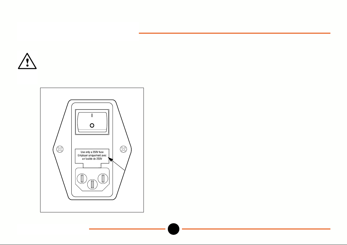
3.0: Service & Repair
Replacing the fuse
At the rear right of the Digital Readout remove
the fuse cover of the IEC320 connector and
replace the fuse with the same type and value.
This equipment contains no user serviceable parts
other than the fuse.
This equipment must be returned to your Omega
dealer for all other service and repair.
Dismantling the unit will invalidate the warranty.
Fuse
Cover
3.0: Service & Repair
"
M-3482 02/99DR601
Page 7

4.0: Measurement Configurations
Individual probe - connection of one Linear
Encoder or Digital Probe.
Probe pair - connection of 2 probes
configured as A+B or A-B.
Probes may be plugged directly into the rear panel
recessed receptacle.
Multiple probes - up to 10 individual probes
or probe pairs (A+B or A-B)
each allocated to a program.
Scan - connection of up to 30
probes (Linear Encoders
and/or Digital Probes) and
allocated to a single
program.
Refer to Digital Benchtop Meter User Manual to
configure the options.
To connect more than 2 probes to the Digital Readout,
use the Orbit Network Connection System.
When more than 10 probes are connected to the Digital
Readout a supplementary power supply interface
module will be required (Omega Part No. LDN-PS).
4.0 Measurement Configurations
#
M-3482 02/99DR601
Page 8

5.0: Digital Readout Interface
RS232
IEC 320 CONNECTOR
85V - 264V
15W max
INPUT/
OUTPUT
CONNECTOR
CONNECTOR
PROBE INTERFACE/
ORBIT NETWORK
CONNECTORS
Earth stud provided
for bond ing to machine
safety earth.
(CAUTION: DO NO T USE
FOR CONNECTION TO LVDT
OR HALF BRIDGE GAUGING
PROBES)
MOTOR DRIVE CONNECTION
Probe(s) must be identified to the Digital Readout when first installed. Simply press probe tip when prompted.
5.1 Connecting 1 or 2 Probes
To connect a Linear Encoder or Digital Probe ensure cable from Probe Interface Electronics (PIE) is at bottom of unit
and plug into either left hand or right hand side of recessed receptacle.
5.0: Digital Readout Interface
DR601
$
M-3482 02/99
Page 9

5.0: Digital Readout Interface (Continued)
5.2 Connecting up to 30 probes
Accessories
T-CON part number LDN-CON
9 pin (m/f) cable 1.5 m / 5 ft 006869
9 pin (m/f) cable 5 m / 16 ft 803664
5.0: Digital Readout Interface
DR601
%
M-3482 02/99
Page 10

6.0: Probe Interface/Orbit Network Connections
Connector type: 9 pin D-sub female
Pin Function
10V
2 RS485(A)
3 RS485(B)
40V
50V
6 +5V
7 +5V
8 +5V
1
2
3
4
5
6
7
8
9
1
2
3
4
5
6
7
8
9
90V
Probe Interface/Orbit
6.0: Network Connections
DR601
View from rear of unit
&
M-3482 02/99
Page 11

7.0: RS232
(Allows measurement readings to be sent to printer or
PC)
Connector type 25 pin D-sub female
13
12 11 10 9 8 7 6 5 4 3 2 1
25 24 23 22
21 20 19 18 17 16 15 14
7.1 Pin Assignment
Pin Signal Assignment
1 CHASSIS GND Chassis ground
2 TXD Transmitted data
3 RXD Received data
4 RTS Request to send
5 CTS Clear to send
6 DSR Data set ready
7 SIGN GND Signal ground
20 DTR Data terminal ready
7.2 Voltage levels
TXD and RXD voltage levels
logic level (active) -3V to -15V
logic level (not active) +3V to +15V
RTS, CTS, DSR and DTR voltage levels
logic level (active) +3V to +15V
logic level (not active) -3V to -15V
7.3 Connection cable
Simple connection between Digital Readout and
printer or PC
(No flow control or Xon/Xoff flow control)
1 1 Chassis gnd
2 2 TXD
3 3 RXD
7
Digital Readout Printer or PC
7 Signal gnd
RTS/CTS Control = no
&
DTR/DSR Control = no
in RS232 menu
7.0: RS232
DR601
'
M-3482 02/99
Page 12

7.0: RS232 (Continued)
1
2
3
4
5
6
7
8
20
1
2
3
4
5
6
7
8
20
Chassis gnd
TXD
RXD
RTS
CTS
DSR
Signal gnd
DCD
DTR
RTS/CTS Control = yes
&
DTR/DSR Control = yes
in RS232 menu
Digital Readout Printer or PC
Connection between Digital Readout & printer or PC
using RTS/CTS and DTR/DSR
7.4 Baud Rate 300, 600, 1200, 2400, 4800,
9600, 19200, 28800, 57600
7.5 Data Format 1 start bit
Note: Baud rate and data format options are defined in
RS232 menu. Ensure settings are the same as on the
connected serial device.
7.0: RS232
7 data bits
none/odd/even parity
1 or 2 stop bits
7.6 Message format
Digital Readout to PC or printer
Message:<Displayed Measurement>
Initiated by<Send Measurement>command or by
pressing print key
1 9 10 20 21 22 23
Text Reading U R
Message terminated by [carriage return] [line feed]
Key:
Text: ASCII text dependant on mode of operation
(Bytes 1 to 9)
Reading: ASCII representation of the reading, leading
zeros replaced by spaces
(Bytes 10 to 20)
U = units for inches (Byte 21)
space for mm
R = range lamps > out of tolerance - high (Byte 23)
= in tolerance
< out of tolerance - low
M-3482 02/99DR601
Page 13

7.0: RS232 (continued)
PC or printer to Digital Readout
Command Character Description
<Send Measurement> STX Requests displayed measurement to be sent
<X OFF> DC3 Stop transmission of message
<X ON> DC1 Restart transmission of message
Freeze display
The numeric display reading can be programmed to freeze when RS232 option is
selected in ext menu.
Display frozen and updated by each freeze = RS232
<Send Measurement> command on RS232 interface in ext menu
7.0: RS232
DR601
M-3482 02/99
Page 14

13
2120191817161514 25
24
2322
1211109876
5
4321
8.0: Input/Output Connections
Allows remote switches or inputs to be used in place of
Digital Readout keys and displayed value to be frozen.
Range Lamp status can be used to control external
relays.
Input/Output (25 pin D-sub Male connector)
Viewed from rear of unit.
Inputs
High +3.9V to +15V (max)
Low -0.5V to +0.9V(Io ~5mA)
Pin Function
2 Remote ZERO
3 Remote LOAD
4 Remote PRINT
5 Remote Reset MAX/MIN/DIFF registers
6 Remote display
MAX/MIN/DIFF/ACTUAL, key press
cycles
7 Remote Freeze Display
8 Remote Program Up
9 Remote Program Down
22 Remote MOTOR
23 Remote MOTOR
24 Unassigned
25 Unassigned
8.0 Input/Output Connections
DR601
M-3482 02/99
Page 15

8.0: Input/Output Connections (Continued)
Remote ZERO: Performs same function as
pressing zero key when input is taken low then
high.
Remote LOAD: Performs same function as
pressing load soft key when input is taken low
then high in Operation mode preset or Max/min
menu.
Remote PRINT: Performs same function as pressing
print key when input is taken low then high.
Remote MAX/MIN/DIFF: Performs same
function as pressing soft key that cycles
through actual/maximum/minimum/difference in
Operation mode Max/min menu, when input is
taken low, then high.
Remote RESET: Performs same function as
pressing reset soft key in Operation mode
Max/min menu, when input is taken low, then
high.
Remote Freeze
The Digital Readout can be programmed to
freeze the displayed reading as follows:
Display frozen and updated by each negative
going edge on Remote Freeze Display signal.
freeze = remote neg edge in ext menu.
Display frozen while Remote Freeze Display
signal is low.
freeze = remote low in ext menu.
8.0: Input/Output Connections
!
M-3482 02/99DR601
Page 16

8.0: Input/Output Connections (Continued)
Remote Program Up/Down performs the same
function as pressing the program keys
when input is taken low then high.
Motor /Motor performs the same function as
pressing the motor keys when input is held
low.
Input Schematic
+5V
1K
Input
0V
Io
10K
0V
t
min ≥ 20mSec
0V
0V
Active low, edge triggered.
Only one input to be active at a time.
If a series of functions is being processed then
t
min may be prolonged.
Outputs
High +32V (max)
Ic ≤ =10µA
Low ≤ +0.4V
Ic ≤ 100mA
Pin Function
15 Not assigned
16 Range lamps: Within tolerance
17 Range lamps: Low
18 Range lamps: High
19 Do not connect
20 Do not connect
8.0: Input/Output Connections
"
M-3482 02/99DR601
Page 17

8.0: Input/Output Connections (Continued)
Misc.
Pin Function
10V
10 0V
11 Unused
12 Unused
13 Unused
14 Unused
21 Unused
Output schematic
Open Collector, active low
Range lamps within tolerance/low/high operate on
actual limit set values with no hysteresis
Delay until signal output: £ 50mSec
(If a series of functions is being processed this may
be prolonged)
8.0: Input/Output Connections
#
M-3482 02/99DR601
Page 18

9.0: Motor Drive Connections
Provides dc power for probe motor drive.
Pin Function
1 Motor +
2 Motor -
3 12V
40V
5 Spare
5 pin DIN female connector viewed from rear of unit.
3
2
1
When motor key or remote Motor selected then
Motor + = +12V
Motor - = 0V
4
5
When key or remote Motor selected then
Motor + = 0V
Motor - = +12V
When no motor keys or inputs selected then
Motor + = 0V
Motor - = 0V
Maximum current from +12V is 100mA
9.0: Motor Drive Connections
$
M-3482 02/99DR601
Page 19

10.0: General Specification
ENVIRONMENTAL
Operating Temperature (°C) 0 to 40°C / 32 to 104°F
Storage Temperature (°C) -20 to 60°C / -4 to 140°F
Humidity 0 to 95% non condensing
Safety Rating EN61010-1
IP Rating
Front panel module IP65
Complete unit IP40
EMC
Emission EN50081-1
Immunity EN50082-2
Power supply via IEC 320 Connector
Line voltage 85V to 264V
Line frequency 47Hz to 440Hz
Power 15W max
Line fuse 2A T
Fuse size 20mm
Nominal Dimensions
Width 235mm / 9.26 in
Height w/o feet 80mm / 3.15 in
Height w/ feet 96mm / 3.78 in
Depth 190mm / 7.49 in
Weight 2.3kg / 3.3 lbs
10.0: General Specification
%
M-3482 02/99DR601
Page 20

WARRANTY/DISCLAIMER
OMEGA ENGINEERING, INC. warrants this unit to be free of defects in materials and
workmanship for a period of 13 months from date of purchase. OMEGA Warranty adds
an additional one (1) month grace period to the normal one (1) year product
warranty to cover handling and shipping time. This ensures that OMEGAs customers
receive maximum coverage on each product.
If the unit malfunctions, it must be returned to the factory for evaluation. OMEGAs
Customer Service Department will issue an Authorized Return (AR) number immediately
upon phone or written request. Upon examination by OMEGA, if the unit is found to be
defective, it will be repaired or replaced at no charge. OMEGAs WARRANTY does not
apply to defects resulting from any action of the purchaser, including but not limited to
mishandling, improper interfacing, operation outside of design limits, improper repair, or
unauthorized modification. This WARRANTY is VOID if the unit shows evidence of having
been tampered with or shows evidence of having been damaged as a result of excessive
corrosion; or current, heat, moisture or vibration; improper specification; misapplication;
misuse or other operating conditions outside of OMEGAs control. Components which
wear are not warranted, including but not limited to contact points, fuses, and triacs.
OMEGA is pleased to offer suggestions on the use of its various products. However,
OMEGA neither assumes responsibility for any omissions or errors nor assumes
liability for any damages that result from the use of its products in accordance with
information provided by OMEGA, either verbal or written. OMEGA warrants only that the
parts manufactured by it will be as specified and free of defects. OMEGA MAKES NO
OTHER WARRANTIES OR REPRESENTATIONS OF ANY KIND WHATSOEVER,
EXPRESS OR IMPLIED, EXCEPT THAT OF TITLE, AND ALL IMPLIED WARRANTIES
INCLUDING ANY WARRANTY OF MERCHANTABILITY AND FITNESS FOR A
PARTICULAR PURPOSE ARE HEREBY DISCLAIMED. LIMITATION OF LIABILITY: The
remedies of purchaser set forth herein are exclusive, and the total liability of OMEGA
with respect to this order, whether based on contract, warranty, negligence,
indemnification, strict liability or otherwise, shall not exceed the purchase price of the
component upon which liability is based. In no event shall OMEGA be liable for
consequential, incidental or special damages.
CONDITIONS: Equipment sold by OMEGA is not intended to be used, nor shall it be
used: (1) as a Basic Component under 10 CFR 21 (NRC), used in or with any nuclear
installation or activity; or (2) in medical applications or used on humans. Should any
Product(s) be used in or with any nuclear installation or activity, medical application,
used on humans, or misused in any way, OMEGA assumes no responsibility as set
forth in our basic WARRANTY/ DISCLAIMER language, and, additionally, purchaser will
indemnify OMEGA and hold OMEGA harmless from any liability or damage whatsoever
arising out of the use of the Product(s) in such a manner.
RETURN REQUESTS / INQUIRIES
Direct all warranty and repair requests/inquiries to the OMEGA Customer Service
Department. BEFORE RETURNING ANY PRODUCT(S) TO OMEGA, PURCHASER
MUST OBTAIN AN AUTHORIZED RETURN (AR) NUMBER FROM OMEGAS
CUSTOMER SERVICE DEPARTMENT (IN ORDER TO AVOID PROCESSING DELAYS).
The assigned AR number should then be marked on the outside of the return package
and on any correspondence.
The purchaser is responsible for shipping charges, freight, insurance and proper
packaging to prevent breakage in transit.
FOR W
ARRANTY RETURNS, please
have the following information available
BEFORE contacting OMEGA:
1. Purchase Order number under
which the product was
PURCHASED,
2. Model and serial number of the
product under warranty, and
3. Repair instructions and/or specific
problems relative to the product.
OMEGAs policy is to make running changes, not model changes, whenever an
improvement is possible. This affords our customers the latest in technology and
engineering.
OMEGA is a registered trademark of OMEGA ENGINEERING, INC.
© Copyright 1998 OMEGA ENGINEERING, INC. All rights reserved. This document
may not be copied, photocopied, reproduced, translated, or reduced to any electronic
medium or machine-readable form, in whole or in part, without the prior written consent
of OMEGA ENGINEERING, INC.
FOR NON-WARRANTY REPAIRS,
consult OMEGA for current repair
charges. Have the following information
available BEFORE contacting OMEGA:
1. Purchase Order number to cover
the
COST of the repair,
2. Model and serial number of the
3. Repair instructions and/or specific
product, and
problems relative to the product.
M-3482 02/99DR601
Page 21

Where Do I Find Everything I Need for
Process Measurement and Control?
TEMPERATURE
G
Thermocouple, RTD & Thermistor Probes, Connectors,
Panels & Assemblies
G
Wire: Thermocouple, RTD & Thermistor
G
Calibrators & Ice Point References
G
Recorders, Controllers & Process Monitors
G
Infrared Pyrometers
PRESSURE, STRAIN AND FORCE
G
Transducers & Strain Gauges
G
Load Cells & Pressure Gauges
G
Displacement Transducers
G
Instrumentation & Accessories
OMEGAOf Course!
DATA ACQUISITION
G
Data Acquisition & Engineering Software
G
Communications-Based Acquisition Systems
G
Plug-in Cards for Apple, IBM & Compatibles
G
Datalogging Systems
G
Recorders, Printers & Plotters
HEATERS
G
Heating Cable
G
Cartridge & Strip Heaters
G
Immersion & Band Heaters
G
Flexible Heaters
G
Laboratory Heaters
FLOW/LEVEL
G
Rotameters, Gas Mass Flowmeters & Flow Computers
G
Air Velocity Indicators
G
Turbine/Paddlewheel Systems
G
Totalizers & Batch Controllers
pH/CONDUCTIVITY
G
pH Electrodes, Testers & Accessories
G
Benchtop/Laboratory Meters
G
Controllers, Calibrators, Simulators & Pumps
G
Industrial pH & Conductivity Equipment
ENVIRONMENTAL
MONITORING AND CONTROL
G
Metering & Control Instrumentation
G
Refractometers
G
Pumps & Tubing
G
Air, Soil & Water Monitors
G
Industrial Water & Wastewater Treatment
G
pH, Conductivity & Dissolved Oxygen Instruments
M-3482 02/99DR601
 Loading...