

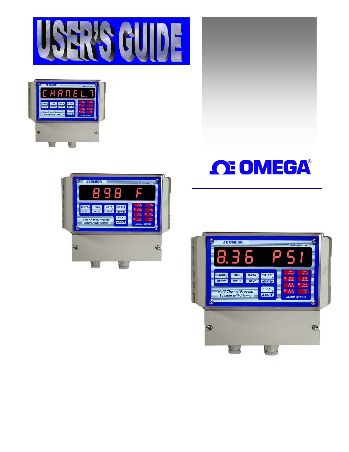
Omega Products DPS3304 Installation Manual
http://www.omega.com
e-mail: info@omega.com
DPS3300 Series
wall mount Multi-Channel
Process Scanner

TABLE OF CONTENTS
SPECIFICATIONS ................................................................................................................................................................ 3
DESCRIPTION...................................................................................................................................................................... 5
DISPLAYING PARAMETERS............................................................................................................................................. 6
Table 1. How to Display Parameters................................................................................................................................. 6
DISPLAY MODES ............................................................................................................................................................ 7
Table 2. Display Modes..................................................................................................................................................... 7
Elapsed Time Mode............................................................................................................................................................ 7
Scan Mode.......................................................................................................................................................................... 8
High/Low Channel Mode................................................................................................................................................... 8
Deviation Mode.................................................................................................................................................................. 9
Types of Deviation Displays .......................................................................................................................................... 9
Difference Mode................................................................................................................................................................. 9
SETUP.................................................................................................................................................................................... 9
'SYS' Parameter List......................................................................................................................................................... 10
CH Parameter List............................................................................................................................................................ 10
CHANNEL CONFIGURATION......................................................................................................................................... 11
Setup For Input Type.................................................................................................................................................... 11
Setup for Voltage or Current Input:.................................................................................................................................. 11
Setup For Channel ON/OFF......................................................................................................................................... 11
Setup For Decimal Point Position ................................................................................................................................ 11
Setup For High Scale.................................................................................................................................................... 12
Setup For Low Scale .................................................................................................................................................... 12
Setup For Offset ........................................................................................................................................................... 12
Setup For Tare.............................................................................................................................................................. 12
Setup For Setpoint ........................................................................................................................................................ 13
Setup for Universal Relay (Channel 1 Relay) .............................................................................................................. 13
Setup For Limits........................................................................................................................................................... 13
Setup For Deadband ..................................................................................................................................................... 13
Setup For Relay Normally Open/Closed ...................................................................................................................... 13
Setup For Engineering Units ........................................................................................................................................ 14
Setup for Thermocouple/ Thermistor/ RTD Inputs: ......................................................................................................... 14
Turning Channels ON/OFF:......................................................................................................................................... 14
Temperature units:........................................................................................................................................................ 14
Setup Examples ................................................................................................................................................................ 15
Example #1: Use of the OFFSET Parameter................................................................................................................ 15
Example #2: Use of the LOW SCALE Parameter........................................................................................................ 15
Example #3: Use of the TARE Parameter.................................................................................................................... 15
SYSTEM CONFIGURATION ............................................................................................................................................ 15
Setup For Display Options ............................................................................................................................................... 15
Table 3. Display Options............................................................................................................................................. 15
Setup For Display Time.................................................................................................................................................... 16
Setup For Relay Latch/Non-Latch.................................................................................................................................... 16
Relay Latched Mode: ................................................................................................................................................... 16
Relay Non-Latched Mode: ........................................................................................................................................... 16
Setup for Buzzer............................................................................................................................................................... 16
Setup For Cold Junction Calibration ................................................................................................................................ 16
Setup For Channel Calibration ......................................................................................................................................... 17
Input Range Setup (for current and voltage): ................................................................................................................... 17
Voltage Range Setup (0-10vdc, 0-5vdc) ...................................................................................................................... 17
Voltage Range Setup (for millivolt inputs) .................................................................................................................. 17
Current Range Setup..................................................................................................................................................... 17
Correct Range Settings ................................................................................................................................................. 17
Thermocouple Calibration Procedure............................................................................................................................... 17
SAVING PARAMETER:..................................................................................................................................................... 18
PEAKS ................................................................................................................................................................................. 18
PROGRAMMING FLOW CHARTS:.................................................................................................................................. 19
RATE ................................................................................................................................................................................... 22
LIMITS................................................................................................................................................................................. 22
OUTPUTS............................................................................................................................................................................ 22
Open Collector Option ..................................................................................................................................................... 22
Figure 1. Open Collector Hookup Example ................................................................................................................ 22
Page 1

TABLE OF CONTENTS
Electro-Mechanical Relay Option .................................................................................................................................... 22
Figure 2. Electro-mechanical Relays Hookup Example............................................................................................... 22
FIG- 3. DPS3300 Series terminal compartment.................................................................................................................. 23
POWER................................................................................................................................................................................ 24
INPUT CONNECTOR PIN ASSIGNMENT....................................................................................................................... 24
Table 4. DPS3300 Series Output Connector Pin Assignments......................................................................................... 24
DIRECT INTERFACE TO UNIVERSAL RELAY MODULE........................................................................................... 25
TROUBLE SHOOTING ...................................................................................................................................................... 26
Factory Channel settings: ................................................................................................................................................. 26
Factory default settings for Thermocouple, voltage, current and milli-volt are: .............................................................. 26
ERROR MESSAGES AND SOLUTIONS .......................................................................................................................... 26
MOUNTING ........................................................................................................................................................................ 27
Figure - 4. Rear View And Mounting Hole Locations .................................................................................................... 27
WARRANTY....................................................................................................................................................................... 28
Page 2

SPECIFICATIONS
(Typical @ 25C and rated supply voltage unless otherwise specified)
STANDARD INPUTS
* 4-20ma 0-50ma 0-5Vdc 0-10Vdc
* Thermocouple inputs: J, K, T, E, R, S, and B
* Cold junction compensation error: +/- 1C (10C to 40C)
* Open input indication: HELP displayed
* Temperature displayable in Degrees C or F
* Non-standard inputs available --- consult factory.
ANALOG TO DIGITAL CONVERSION
* 4-1/2 Digit (20,000) Count) A/D Converter
* Dual slope integrating converter with 7 conversions /sec. (typical) rate.
SCAN RATE
* Fixed: two channels per second
DISPLAY
* Red seven segment displays--0.8" (20mm) digit height
* Over range indication: HELP
* Display test: Briefly displays 8.8.8.8.8.8.8 on power up.
* Seven-digit display
SCALE/OFFSET
* Scale programmable from 1 - 30000 units
* Offset programmable from 0 - 99.99mA (For mA Input)
* Offset programmable from 0 - 9.999V (For Voltage Input)
* Programmable decimal point.
RELIABILITY/ACCURACY
*Calibration: NIST traceable (for thermocouples)
*Temperature resolution: 1C/1F
* Warranty: 1 Year
* Recalibration recommended at 12-month interval
POWER REQUIREMENT
* 120Vac --- 60 HZ (Standard)
* 240Vac --- 50 HZ (optional)
* 15VDC (optional)
OUTPUT (optional)
* Open collector outputs -- 50ma maximum sink, limited to 50ma per output
* Relays: Single pole single throw, 1 Amp @ 28Vdc or 0.5 Amp @ 120Vac resistive
*Output termination: Euro-style plug-in connector
Page 3

DPS3304 & DPS3314 are four channel units. Therefore, any reference to channel numbers with
respect to these models is for channels 1 through 4 only.
DPS3307 and DPS3317 are seven channel units, and therefore, any reference to channel
numbers for these models is for channels 1 through 7.
DPS3304 & DPS3307 are base models that accept only one type of transducer signal on all
four/seven inputs.
DPS3314 & DPS3317 are enhanced models that have fully programmable inputs and each
channel can be configured independently to accept a low voltage signal (T/C, RTD, Thermistor,
milliVolt) or a voltage signal (0-5Vdc, 0-10Vdc) or a loop current signal (4-20mA, 0-50mA).
NOTE
Page 4
DESCRIPTION
DPS3300 Series instruments are multi-channel scanners that pack a number of functions into one unit. Tasks that require
multiple monitors can now be accomplished by using only a single unit. Signals from a number of different transducers
can be brought into screw terminals that are conveniently located on the back panel of the instrument. The unit
automatically scans through each channel, displaying the channel number and process value. In addition to displaying
temperature, pressure, strain, etc. these units also boast some of the most frequently used functions such as process
differential between channels, monitoring high and low readings on individual channels, rate of change, tracking channels
with highest and lowest readings, comparison of process with a preset set-point, etc.
Signals from thermocouples are linearized and can be displayed in degrees Celsius or Fahrenheit. Transducers that put out
4-20 ma. current loop, 0-5Vdc, or other linear signals can be scaled from the front keys. This gives the flexibility of
displaying various parameters directly in engineering units. Channels that do not have signals connected to them may be
programmed off by the operator and will not be scanned or displayed.
On power up (check for proper power connections before powering up) the unit will first display 8.8.8.8.8.8.8. as a display
test and then the software revision number. The format is 'rEn x.xx' where x.xx is the revision level.
NOTE: Check model number for input type & display units -- thermocouples, 4-20ma, 0-10Vdc etc...
MODEL NO. DESCRIPTION
DPS3304 - (a) - (b) - (c) 4 Channel, fixed input scanner
DPS3314 - (a) - (b) - (c) 4 Channel, programmable input scanner
DPS3307 - (a) - (b) - (c) 7 Channel, fixed input scanner
DPS3317 - (a) - (b) - (c) 7 Channel, programmable input scanner
(a) INPUT TYPE (a) INPUT TYPE
TC J, K, T or E T /C C 4-20ma current
R ‘R’ thermocouple
S ‘S’ thermocouple
B ‘B’ thermocouple (a) INPUT TYPE
RTD RTD (385, 392)
TH Thermistor (400 Series) V 0-10 volt DC
P 100 millivolt
(b) POWER (c) OUTPUTS
Blank 120VAC Power Input (standard) 5/3 4/7 Relay Outputs (optional)
1 240VAC Power Input (optional) 6/4 4/7 Open Collector Outputs (optional)
2 15Vdc Power Input (optional) Blank No Output (standard)
Page 5

DISPLAYING PARAMETERS
DPS3300 Series keeps track of various parameters and these may be displayed by pushing appropriate keys on the front
panel. The parameters that are tracked are:
a) Channel's high peak d) Channel with the lowest reading
b) Channel's low peak e) Process deviation of each channel from pre-programmed setpoint
c) Elapsed time f) Process differential of a channel with respect to any other channel
c) Channel with the highest reading g) Rate of process change per minute for each channel
Table 1 explains how to display the above mentioned parameters.
Table 1. How to Display Parameters
TO DISPLAY PERFORM FOLLOWING STEPS
1) Channel's high peak a) Select channel whose high peak is desired (push CH SEL key)
b) Push HI/LO key once
2) Channel's low peak a) Select channel whose low peak is desired (push CH SEL key)
b) Push HI/LO key twice --- 1st push displays high peak,
2nd push , low peak.
3) Rate of process change a) Select channel whose Rate is desired (push CH SEL key)
b) Push DATA key once.
4) Channel deviation a) Select desired channel (by pushing CH SEL key)
b) Push DATA key twice --- 1st push displays rate,
2nd push, deviation.
5) Channel differentials a) Select desired channel (by pushing CH SEL key).
b) Push DATA key three times -- 1st push displays rate,
2nd push: deviation, 3rd push : differential.
c) Each additional push moves to the differential between selected
channel and the next channel.
d) e.g. the sequence for channel 1 is: RATE, CH1-SP, CH1-CH2,
CH1-CH3, CH1-CH4, CH1-CH5, CH1-CH6, CH1-CH7
6) Elapsed time a) Push TIME key.
7) Channel with highest a) Push HI/LO key once
process reading
8) Channel with lowest a) Push HI/LO key twice ----1st push: high channel
process reading 2nd push: low channel.
9) Scan a) If the unit is holding, push the SCN/HLD key once.
10)Hold a) If the unit is scanning, push the SCN/HLD key once.
Page 6
DISPLAY MODES
DPS3300 Series has multiple display modes and can be programmed to either scan, display the channel with the highest
reading, display the channel with the lowest reading, deviation between channel's process variable and a pre-programmed
setpoint, difference between any two selected channels or just run as a timer. In the timer mode the unit keeps track of
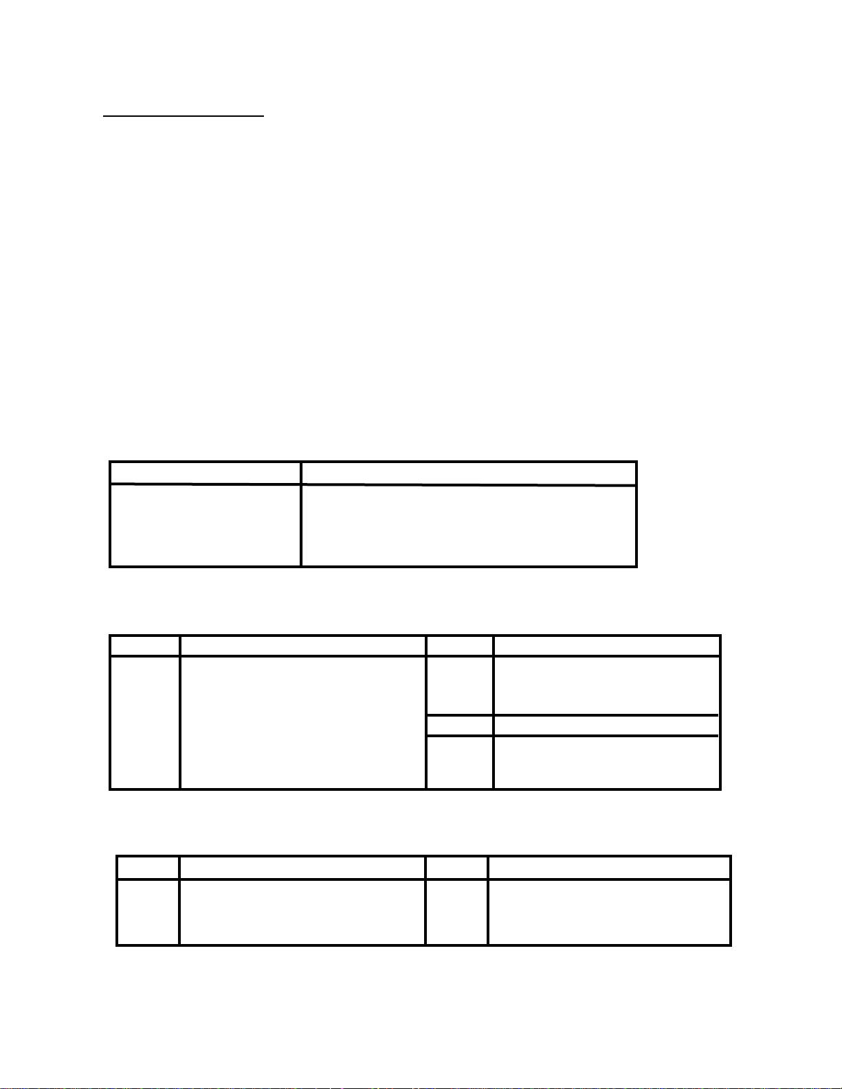
process run time with crystal controlled accuracy. Elapsed Time display format is 'HH.MM.SS' for hours, minutes, and
seconds. The desired display mode is selected during SYS SETUP ---- (for details refer to the SYS CONFIGURATION
section).
Table 2. Display Modes
MODE FUNCTION PERFORMED
1) Elapsed time Unit displays elapsed time since power up or last time reset.
2) Scan All active channels are automatically scanned.
Channels that are turned off are not scanned or displayed.
3) High Channel The unit will compare all active channels against each other and
display the one that has the highest process reading.
4) Low Channel The unit will compare all active channels against each other and
display the one that has the lowest process reading.
5) Deviation The unit scans all active channels and displays the deviation of
process variable from a pre-programmed setpoint.
6) Channel Differential The unit continuously displays the difference of process between
any two selected channels.
The following paragraphs give a detailed description and operation of various modes.
Elapsed Time Mode
DPS3300 Series can be programmed to run as timer. In this mode the unit will
indicate elapsed time in hours, minutes and seconds. The display format is
'HH.MM.SS'. This mode is selected during SYS Setup by opting for
'ELPSD t'. The elapsed time is the time passed since the unit was turned on or
when the time was last reset. To reset the time, first push the TIME key and
while keeping it pressed, push the RESET key. The display will show
'rESEt' and on release of the RESET key, the display will reset to '00.00.00'
and begin timing.
The elapsed time can also be momentarily displayed while the unit is
operating in any other display mode. This is done by pushing the TIME key
once. The unit will first display the word 'ELPSd t' followed by the elapsed time. This will stay in the display window for
a brief period and then the unit will revert to the normal display mode.
Page 7
Scan Mode
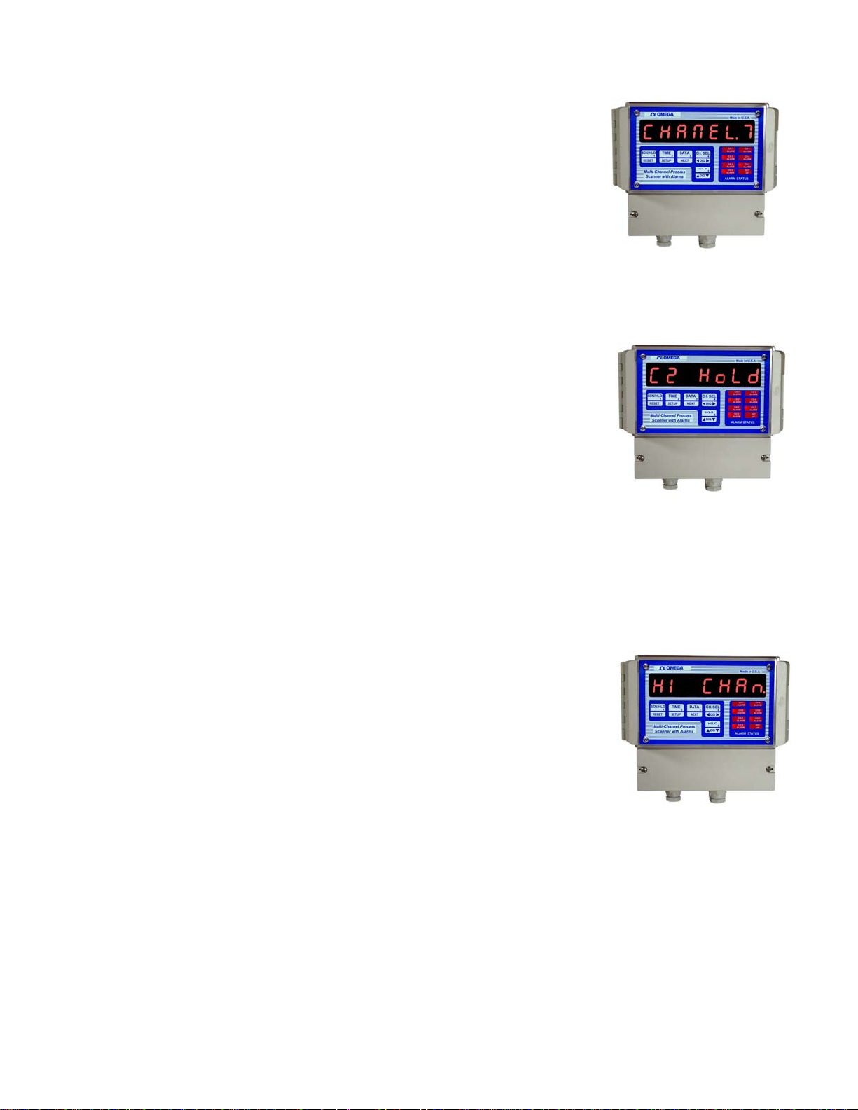
When setup for scan mode, individual channels are displayed for a programmed
period of time. At the end of that time period the, display automatically switches
to the next channel. For ease of reading, the display first shows the channel
number (Format: 'CHANEL 1') and then the process variable along with the
programmed three digit engineering units e.g. 23.45 PSI.
Display time for each channel is programmable from 1-999 seconds (16.65 min.).
This is useful for adjusting display time to a rate which is consistent with the type
of process being monitored. Scan time for each channel is independent of display
time. This permits programming long display times without losing track of the
process on other channels.
The display can also be put in a hold mode by pushing the SCN/HLD key. When this key is pushed, the display will
briefly show 'HOLd' after which the display will stop on the channel it was
indicating. Putting the unit in HOLD mode inhibits automatic display scanning
and shows only one particular channel. While the display is held on one channel,
internally all the enabled channels are continuously scanned for rate, difference,
limits and other parameters. Also, during HOLD mode the unit will periodically
flash the display 'Cx HOLd' ( x=channel # on hold) to indicate the status of the
display mode. If an attempt is made to hold on a channel that has been turned off
then the unit will indicate so by displaying in the format 'CHx OFF' (
x=channel # off).
To select another channel for display during hold mode, push the CH. SEL
key. Each push will increment the channel number. The display will first show
the channel number (e.g. 'CHANEL 2' for channel # 2) followed by the process
variable in the form '0.123 PSI'. When channel selection is initiated using the CH. SEL key, the unit starts with
channel #1 and steps thru to channel #7 with each push of the key.
To take the unit out of HOLD mode and back into SCAN mode, push the SCN/HLD key. The display will briefly show
'SCAN' and then start scanning the channels.
High/Low Channel Mode
DPS3300 Series compares all the channels against each other and constantly tracks
the channel with the highest and lowest process value. On push of a key, the
channel number and the value of process variable can be displayed. Also, during
SYS Setup, the unit can be programmed so that instead of scanning all the channels
it will only display the channel with highest or lowest process variable. As the
process changes, the display automatically switches over to the channel with the
highest (or lowest, if so programmed) reading. This is a very useful function for
applications involving multi-point monitoring of temperature in a single process.
For example, this feature can be used to find hot spots in a kiln. During high or low
channel scan mode the display will periodically flash 'HI CHAN' or 'LO CHAN' (depending upon the selected mode) to
indicate the status of the display mode.
To display high and low channel from any other display mode simply push the HI/LO key. Pushing this key once will
first display 'HI CHAN' and then the channel number and the process value will be displayed in the format 'C2 1234'.
The second push on the HI/LO key will first show 'LO CHAN' in the display window, and then the channel with the
lowest process value will be displayed.
NOTE: (i) The second push, to display low channel, must be initiated before the display reverts back to the normal
display mode.
(ii) If a channel is selected using the CH. SEL key prior to the push on the HI/LO key, then instead of
displaying high and low channels, the unit will display high and low peaks of the active channel.
Therefore, if it is desired to display high and low channels and not the peaks, do not select a channel
before pushing the HI/LO key.
Page 8
Deviation Mode
In deviation display mode, DPS3300 Series will show the differential between a pre-programmed setpoint and process
variable being monitored on each channel by the scanner. Individual setpoint for each channel is programmed during CH
Setup and can be any value over the range of selected scale or thermocouple being
used.
Types of Deviation Displays
There are two different ways of displaying channel deviation from their setpoint
values:
a) The first one is a momentary display in which the deviation is
indicated for a short time. Following this brief display time, the unit reverts to its
normal mode of operation (scanning, differential, timer etc.). To achieve this, first
select the channel whose setpoint deviation is desired. This is done by pushing the
CH. SEL key. Next, push the DATA key twice. The first push displays the
rate/minute value. The second push will display the deviation value. Before
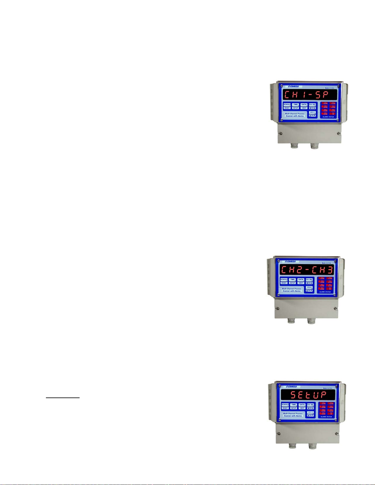
showing the deviation, the display will read 'CH1 - SP' ( for CHannel 1 SetPoint).
b) The second method of displaying deviation is by selecting the 'dSP dEN' option when programming the
Display Option during the SYS Setup. If this method is selected, the display will scan through all the active channels and
display their deviation. The display format is 'd2 1234' (d stands for deviation).
The unit can also be put on HOLD at any channel by pushing the SCN/HLD key. If any other channel's deviation is
desired, it may be obtained by pushing the CH. SEL key. If an attempt is made to hold the display on a channel that has
been turned off, then the unit indicates this by displaying 'CHx OFF' (x=channel #). DPS3300 Series will keep track of
all other parameters while programmed for this mode (i.e. limits, peaks, rate, process value, channel differential etc). All
of these may be displayed by pushing the respective keys.
Difference Mode
In this mode the system continuously displays the difference of process variable
between any two selected channels. The two active channels are selected during
SYS Setup mode. To remind the operator of the current display mode and also
the two channels, the display flashes the channel numbers every few seconds
(e.g. 'CH1 - CH2' for displaying difference between channel #1 and channel #2).
If the unit is not programmed for difference mode, the differential between any
two of the seven channels can be briefly displayed by pressing the DATA key.
The procedure for doing so is to first select the channel whose differential with another channel is desired. This is done by
pushing CH SEL key. Each push on this key will display the selected channel in the format 'CHANEL x'(x=channel #).
When the desired channel has been selected, press the DATA key three times. The first push will display the rate of
process change on that channel. The second push will show the process deviation from the programmed setpoint. The third
push will flash a display of the form 'CH1 - CH2' and then a differential value. Additional pushes on DATA key will
sequence thru the channels and will be indicated as below:
CH1 - CH3, CH1 - CH4, CH1 - CH5, CH1 - CH6, CH1 - CH7, CH1 - SP
SETUP
Setup mode provides a means to customize the monitor to suit a particular
application. It allows programming such parameters as temperature units, limits,
display mode, relay deadband, etc.
SETUP mode has 2 sections:
a) SYS setup section to set system parameters
b) CH setup section to set Channel parameters for each channel.
Page 9
 Loading...