

Omega Products DPI 740 Installation Manual


DPI 740
Precision Pressure Indicator
User Manual
M-2912
@ Omege Engineering, Inc.
This document is the property of Omega Engineering, Inc and maynot, either in part
orwhole, be copied or otherwise reproduced, communicated in any way to third
parties, nor stored in any Data Processing System, without the express written
authority of Omega Engineering, Inc
M-2912 Issue No.1

e..nsse..d
.pe~e1s ~e4~ ue4~
SI8!..e/8W ~!X°.L
e~U8Ue/U!8W
lenuew JaSn 017L Ida
A~ej8S
eq 01 1uewnJ1SU! S!41 peu5!sep se4 JeJm:>e~nuew e4l
S!41 U! pel!e1ep SeJnpe:>oJd e41 5u!sn pe~eJedo Ue4M e~es
esodJndJe4~0"UeJO~1ueWnJ1SU! S!41eSn10U oa .Ienuew
SUO!~:>nJ~SU! "~e~es pue 5u!~eJedo SU!e~UO:> Uo!~e:>!lqnd S!41 o
u!e~u!ew 01 pue Uo!~eJedo 8~eS JO~ peMO110~ eq 1SnW ~e41
SUO!1:>nJ1SU! "~e~es e41 .UO!1!PUO:> e~es e U! 1uewnJ1SU! e4~
.e5ewep JO AJnrU! WOJ~ ~uewd!nbe e4~ pue
.uo!~e:J!lqnd S!4~ U! SaJnpe:JOJd lIe JO~
.~uewnJ~su! e4~ O~ eJnsseJd
8~!Apy 18~!uLl~e.L
Jesn e4~ 1:Je~oJd 01 penSS! SUO!1ne:J JO S5U!UJeM Je41!e eJe
a:J!~:JeJd 5u!Jaeu!5ue p005 pue laUUOSJad *pe!~!lenb esn o
5U!)jJOM a~es wnw!xew e4~ ue4~Je~eeJ5 eJnsseJd "Idde ~OU oa
.~uewnJ~su! S!4~ U! pesn sle!Je~ew :J!XO~ UMOU)j oU eJe eJe41
s,JeJn~:Je~nuew e4~ 5u!sn peu!e~u!ew eq ~snw ~uewnJ~su! e41
e:J!"Jes peZ!J04~ne "q ~no pe!JJe:J eq Pln04s pue SeJnpe:JOJd
.s~ueLU~Jedep e:J!/\JeS S,JeJn~:Je~nUeLU e4~ JO s~ue5e
JO ~ue5e ' JeJn~:Je~nUeLU e4~ ~:Je~UO:J e:J!/\pe le:J!u4:Je~ J°:J
.lenUeLU S!4~ ~o JeeJ e4~ ~e ~S!I e4~ o~ Je~eJ AJe!P!sqns
5u!u!eJ~ ~:JnpoJd e pepue..e e/\e4 ~SnLU uosJed pe!~!lenb V
pue ~ue5e pe~u!odde JO JeJn~:Je~nUeLU e4~ "q ue/\!5 eSJno:J
.~UeLUnJ~SU! S!4~ Uo eSJno:J 5u!u!en e4~ pe~eldLUO:J"lln~SSe:J:Jns
)Je41Jn:l .sell!~:)eJ!p J33 ~UelleleJ e4~ }0 s~ueweJ!nbeJ ~
UO!~:Je~oJd le!~UeSSe e4~ s~eew ~:JnpoJd S!41
e4~ U! pUno} eq Aew spJepue~s pe!ldde }0 Sl!e~ep ~
.uo!~e:J!}!:Jeds ~:JnpoJd
ii
Battery Safety
This instrument is fitted with three size AA batteries either
rechargeable (nickel cadmium) or non-rechargeable
(alkaline).
DPI 740 User Manual
Before storing this instrument remove the batteries
When fitting batteries make sure the electrical contacts are
clean and observe the correct polarity.
The battery compartment should be inspected for
corrosion caused by leaking batteries. Corrosion must be
removed using approved methods*.
When storing and transporting batteries make sure that
they cannot be short circuited. A short circuited battery
can become very hot and can, in certain circumstances,
explode. It is recommended that a suitable container is
used for storing and transporting batteries.
Dispose of old batteries using a safe, approved method.*
*Refer to the Battery Manufacturer for this information.
Software Version
This manual contains operating instructions for instruments
with software version 1.XX. Further changes to the
instrument's software may require a change to the operating
instructions and an issue number change of the manual.
M-2912 Issue No.1
ele:Js-llnf S:J
z~JeH zH
WeJ501!>1 5>1
Jeq!ll!w Jeqw
Je~ew!II!W ww
~IO"!II!W I\w
le:Jsed ed
lenuew ..asn 017£ Ida
suoIJelA9.1qqy
eJe4dsoW~e w~e
pJepue~s 4S!~!J8 S8
pues o~ Jeel:J SIJ
~ueJJn:J ~:JeJ!p Ja
Je~eM fO ~eef O'H~f
le:Jsed 0~:Je4 ed4
Je~ewe!p ep!su! p/!
AJn:JJew fO 4:JU! 5HU!
Je~eM fO 4:JU! O'HU!
le:Jsed 01!>1 ed>l
eJedw'1 !11!W '1w
e~nlOsqe Jeq!II!W e Jeqw
AJn:JJew fO Je~eW 5HW
le:Jsed e5ew ed~
Wn!Wpe:J le>l:Jlu peJ !N
Je~ewe!p ep!S~no p/o
!!!
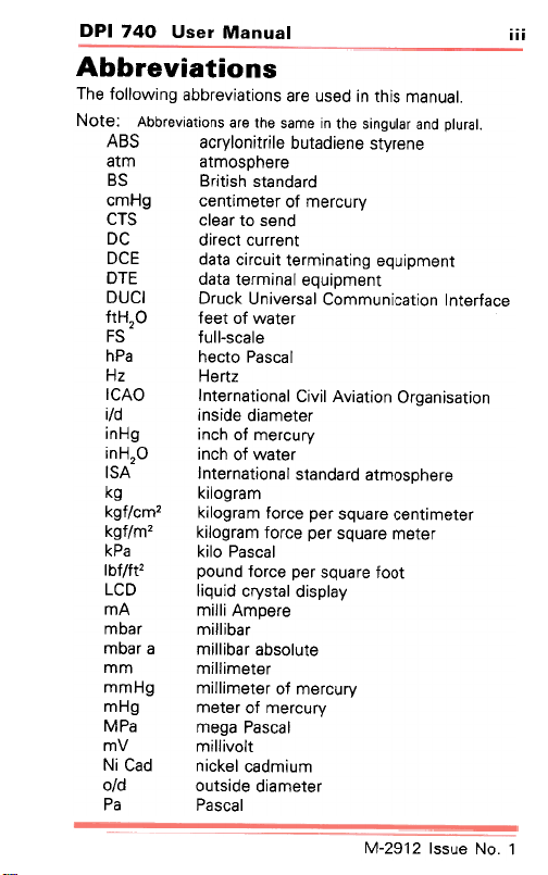
.Ienuew S!4~ U! pesn eJe SUo!~e!"eJqqe 5U!M0110f e41
.leJnld pue jeln6u!s a41 U! awes a41 aJe SUO!le!AaJqqV' :e~oN
eueJA~s eue!pe~nq el!J~!UOIAJ:Je S8'1
AJn:JJew fO Je~eW!~ue:J 5HW:J
~uewd!nbe leu!wJe~ e~ep 31a
Aelds!p le~sAJ:J P!nb!1 aJl
AJn:JJew fO Je~ew!ll!w 5HWW
~uewd!nbe 5u!~eu!wJe~ ~!n:JJ!:J e~ep 3Ja
e:JefJe~ul Uo!~e:J!UnWWOJ lesJe,,!Un >I:JnJa IJna
Uo!~es!ue5JO Uo!~e!,,'1I!"!J leUO!~eUJe~UI O'1JI
eJe4dsoW~e pJepUe~S leUO!~eUJe~UI '1S1
Je~ew!~ue:J eJenbs Jed e:JJOf WeJ501!>1 ,W:J/f5>1
Je~ew eJenbs Jed e:JJOf WeJ501!>1 ,W/f5>1
~OOf eJenbs Jed e:JJOf punod ,~f/fql
l "ON enssl ~l6~-LI\J
iv
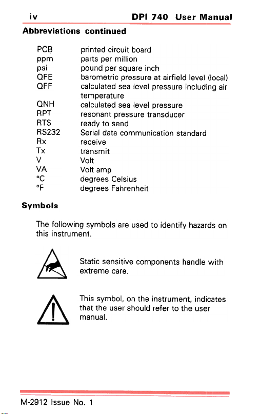
Abbreviations continued
DPI 740 User Manual
PCB
ppm
psi
OFE
OFF
ONH
RPT
RTS
RS232
Rx
Tx
V
VA
oC
of
printed circuit board
parts per million
pound per square inch
barometric pressure at airfield level (local)
calculated sea level pressure including air
temperature
calculated sea level pressure
resonant pressure transducer
ready to send
Serial data communication standard
receive
transmit
Volt
Volt amp
degrees Celsius
degrees Fahrenheit
Symbols
The following symbols are used to identify hazards on
this instrument.
Static sensitive components handle with
&
extreme care.
This symbol, on the instrument, indicates
that the user should refer to the user
manual.
M-2912 Issue No.1
el~!~
lenuew .lasn 011£ Ida
A
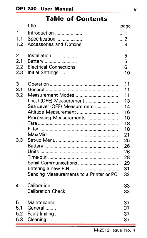
SJU9JUO:> 10 9lqe.l
e6ed
uo!~:>npoJ~ui L
uO!~e:J!l!:>eds L. L
suo!~dO pUB Se!JOSse:>:>\f ~. L
uo!~elle~sul ~
AJe~~e8 L .~
suo!~:Jeuuo:) le:J!J~:JeI3 ~.~
s5u!~~es le!~!ul £.~
~ ...
Z ...
17 ...
9
9
9
OL
uo!1.eJedo £
I eJ e U e ~ l .£
eJ e 1
Je1.I!::1
u!l/IJ/xel/lJ
nuel/lJ dn-1.es £.£
AJe1.1.e8
S1.! U n
1.no-ew!l
v
UO!~eJq!leJ
sepol/lJ 1.UeweJnSeel/lJ l.£
1.ueweJnseel/lJ (3::10) le:J°1
1.UeWeJnSeelAJ (::1::10) leAel ees
1.ueWeJnSeel/lJ epm!1.I'v'
s1.ueweJnseel/lJ 5U!SSe:JOJd
SUO!1.e:JIUnWWOJ le!Jes
Nld MeU e 5u!Je1.U3
>I:J6ljJ UO!~eJq!leJ
e:>ueue~u!el/lJ 9
leJeue':) l.9
.Bu!pu!! ~lne:J z.g
Bu!UeelJ £.g
~ ~
~ ~
~ ~
£~
v~
g~
8~
8~
8~
~Z
gz
gz
gz
8Z
6Z
~£
Z£
Jd JO Je1.u!Jd e 01. S1.ueWeJnSeel/lJ 5u!pues
££
££
LE
LE
LE
LE
l "ON anssl ll6l-~
vi
Table of Contents (contd)
title
6 Communications ..." " , "' , "'.."
6.1 Introduction , "'..." ,.,..." " "..."".."
6,2 General Command Format .." , " "'.
6,3 Command Summary "' "..."' ,,...""..""
6.4 Command Set "...""..""..."' ' " "' '
Input Commands ""..."' "' , " " ,.
Process Commands , ", " " , , Set-up Commands ."...""..."' " " " '
Calibration ComrtJands .." " " " "..
Automatic Commands , " "'..." "..."..
Read Commands ..."'..."".."' "'..."'..." '
Protocol Format Commands ,..." ,,'..." ,
Key Commands .." "'..." "'..."' "..."
DPI 740 User Manual
Table of Illustrations
fig. title
1-1 General view 2-1 Fitting the battery 2-2 Electrical connections 2-3 Adaptor/charger connector 3-1 Instrument front 'panel 3-2 Measurement mode menu 3-3 Local pressure measurement
3-4 Sea level measurement 3-5 Altitude measurement 3-6 Process sub-menu 3-7 MaxiMin menu 3-8 Set-up menu 3-9 Communications set-up 3-10 Calibration
page
...39
...39
...40
...42
...44
...44
...46
...49
...50
...54
...55
...57
...58
page
1
6
8
9
11
12
13
14
16
19
22
25
30
34
M-2912 Issue No.1
lenuew .lesn Ot-L Ida
!!A
l .oN anssl Z l6Z-~
DPI 740 User Manual
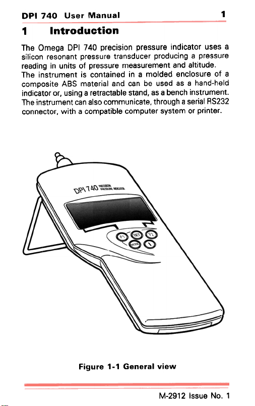
1 Introduction
The Omega DPI 740 precision pressure indicator uses a
silicon resonant pressure transducer producing a pressure
reading in units of pressure measurement and altitude.
The instrument is contained in a molded enclosure of a
composite ABS material and can be used as a hand-held
indicator or. using a retractable stand. as a bench instrument.
The instrument can also communicate. through a serial RS232
connector. with a compatible computer system or printer.
1
Figure 1-1 General view
M-2912 Issue No.1
z
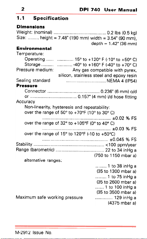
suo!suew!a
.8JmBJ8dw81
5U!!BJ8dO
85BJO!S
e..nssa..d
A:JeJn:J:J';f
uo!~e:)!l!:)ads
18/U9WUOA!AU3
:Wn!p8W 8JnSS8Jd
'Se5UBJ el\!+BUJe+IB
lenuelAl .lesn O~L Ida
(5>! 9'0) sqll'O ..".",.,"',"""""",.,""',.,',.,' (leu!wou) '1,45!8M
'(Ww 06) .179'£ = 41,P!M (ww 06l) .817'L = 1,45!84 ,,"' 8Z!S
(WW 9£) .l17' l = 41,d8p
(J o0L+ O~ o0v-) :J 009L+ O~ o0v- (J009+ O~00L-) :J 00lL+ o~09L
.xeJAd 4~!M elq!~edwo:J se5 Au';f
u!seJ Axode pue lee~s sselu!e~s .uo:J!I!S
(v9dl) v ';f~3N pJepue~s 5u!lees
P/O (WW 9) ,,9£l.0 Jo~:JeuuoJ
5u!~~!~ eso4 P/! (ww v) .L9 L .0 JO
.A~!I!qe~eedeJ pue s!seJe~sA4 .A~!JeeU!I-UON
S:J % lO.O+ (J 00£ O~ 00 L) :Jo0L + O~ oo9 ~O e5ueJ e4~ Jel\o
S:J % £0.0+ (J o0v O~ 00) :J090 L + o~ ol£ ~O e5ueJ e4~ Jel\o
S:J % gvO.O+ b009+ O~ 0 L -) :Jo0l L o~ og L ~o e5ueJ e4~ Jel\o
JeeA/wdd 00 L> A~!I!qe~s
e 5HU! v£ o~ II (:J!J~ewoJeq) e5ue~
(e Jeqw 09 L L o~ 09L)
e 6HU! 8£ o~ L
e 6HU! 9L o~ L (e Jeqw OO£l o~ g£)
e6HU!OOLO~L (e Jeqw 0O9l o~ g£)
eJnsseJd 6U!)jJOM eteS wnw!xe~
e 6HU! 6l L (e Jeqw oog£ o~ g£)
(e Jeqw 9L£P)
"ON enssl ll6l-VIJ
DPI 740 User Manual
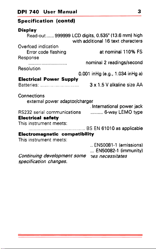
Specification (contd)
Display
Read-out 999999 LCD digits, 0.535' (13.6 mm) high
with additional 16 text characters
Overload indication
Error code flashing
Response
at nominal11 0% FS
nominal 2 readings/second
Resolution
Electrical Power Supply
0.001 inHg (e.g., 1.034 inHg a)
Batteries
Connections
external power adaptor/charger
RS232 serial communications
Electrical safety
This instrument meets:
""""""""""" BS EN 61010 as applicable
Electromagnetic compatibility
This instrument meets"
3 x 1.5 V alkaline size AA
.International power jack
6-way LEMO type
..EN50081-1 (emissions)
...EN50082-1 (immunity)
rJes necessitatesContinuing development some
specification changes.
3
S8!JOSS8:J:JV'
suo!~dO
lenuew .lasn OtrL Ida
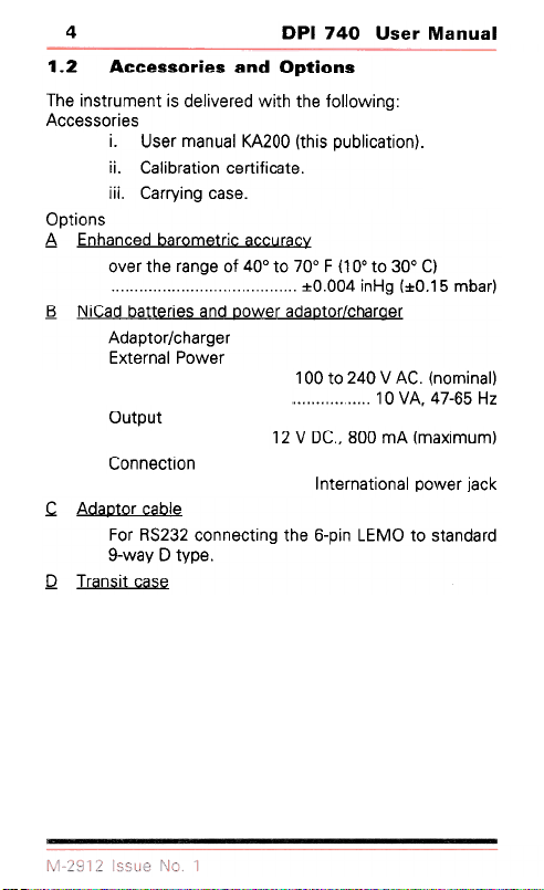
suo!JdO pUR S9!.lOSS9:J:JV Z" ..
.5U!MOIIO~ 84~ 4~!M p8J81\!18P S! ~U8WnJ~SU! 841
(uO!~e:J!lqnd S!4~) OOZ'v'>llenuew J8Sn "!
'e~e:J!~!~Je:J uo!~eJq!leJ "!!
"ese:J 6u!AJJeJ '!!!
A:JeJn:J:Je :J!J~ewoJeq pe:Jue4u3 'V'
(Jeqw 9 L .o~) 6HU! vOO.O~ (J 00£ O~ 00 L) :J o0L O~ o0v to e6ueJ e4~ Jel\o
Je5Je4:J/JO~aepe JeMOa pue Se!Je~~eq peJ!N 8
Je6Je4:J/Jo~dep'11
JeMOd leuJe~x3
~nd~no
alqe:> Jo~OepV' J
ase:> ~!sueJl a
zH 99-L17 "\tA 0 l (leU!WOU) .J'\t A 017~ 0+ 00 l
(wnw!xew) '1W 008 'Ja I\ II
UO!!:JeuuoJ
'i:)e! JeMod leUO!~eUJe~UI
pJepue~s o~ OL"J3l u!d-9 a4~ 5u!~:>auuo:> l£lS~ J°:J
.adA~ a AeM-6
DPI 740 User Manual 5
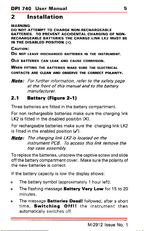
2 Installation
WARNING:
DO NOT ATTEMPT TO CHARGE NON-RECHARGEABLE
BATTERIES. TO PREVENT ACCIDENTAL CHARGING OF NONRECHARGEABLE BATTERIES THE CHARGE LINK LK2 MUST BE
IN THE DISABLED POSITION (X).
CAUTION:
Do NOT LEAVE OISCHARGEO BATTERIES IN THE INSTRUMENT.
OLD BATTERIES CAN LEAK AND CAUSE CORROSION.
WHEN FITTING THE BATTERIES MAKE SURE THE ELECTRICAL
CONTACTS ARE CLEAN AND OBSERVE THE CORRECT POLARnY.
N!lJ#-: For further information. refer to the safety page
at the front of this manual and to the battery
manufacturer.
2.1 Battery (Figure 2-1)
Three batteries are fitted in the battery compartment.
For non rechargeable batteries make sure the charging link
LK2 is fitted in the disabled positibn (X).
For rechargeable batteries make sure the charging link LK2
is fitted in the enabled position (,1).
N!lJ#-: The charging link LK2 is located on the
instrument PCB. To access th,s link remove the
top case assembly.
To replace the batteries, unscrew the captive screw and slide
off the battery compartment cover. Make sure the polarity of
the new batteries is correct.
If the battery capacity is low the display shows:
" The battery symbol (approximately 1 hour left).
" The flashing message Battery Very Low for 15 to 20
minutes.
" The message Batteries Dead! followed, after a short
time, Switching Off!! the instrument then
automatically switches off
M-2912 Issue No.1
9
lenuew .lasn OtrL Ida
4--
~I
el\!~de:J
MeJ:JS
~---:
~<b
~
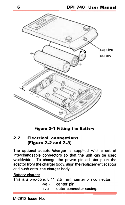
A.la~~eB a4~ 6u!~~!:t L-Z a.ln6!:t
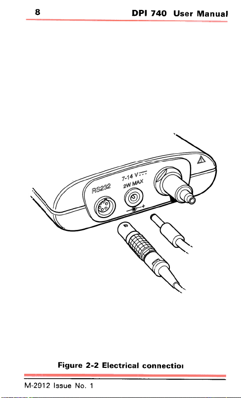
suoIJ:)euuo:) le:)!..J:)913 Z.Z
(E-Z puez-z e..n61.i)
~o ~es e 4~!M pe!lddns S! Je5Je4:J/Jo~depe leUo!~do e41
pesn eq ue:J ~!Un e4~ ~e4~ os SJO~:Jeuuo:J elqee5ue4:JJe~U!
e4~ 4snd Jo~depe u!d JeMod e4~ e5ue4:J 01 .ep!MPIJOM
.ApoqJe5Je4:Je4~ 0~u04sndpue
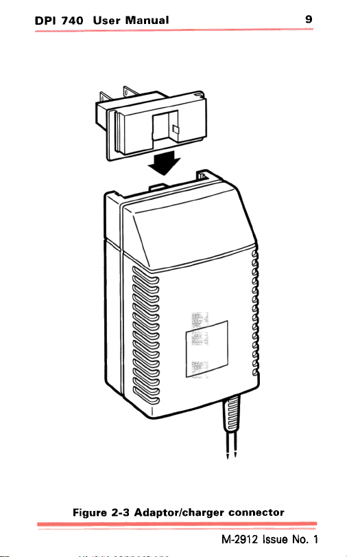
Je6Je4:J Ne~~e8
.u!d Je~ue:J -el\-
.5u!se:J JO~:Jeuuo:J Je~no -el\+
Jo~depe ~ueUJe:JeldeJ e4~ u5!le .Apoq Je5Je4:J e4~ UJOJ~ Jo~depe
:JO~:Jeuuo:J u!d Je~ue:J .(UJUJ g.~) .L .0 .elod-OM~ e S! S!41
'oN enssl Z l6Z-~
DPI 740 User Manual
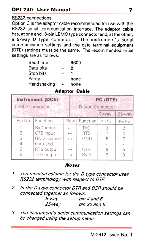
R$232 connections
Option C is the adaptor cable recommended for use with the
RS232 serial communication interface. The adaptor cable
has, at one end, 6-pin LEMO type connector and, at the other,
a 9-way D type connector. The instrument's serial
communication settings and the data terminal equipment
(DTE) settings must be the same. The recommended initial
settings are as follows:
Baud rate 9600
Data bits 8
Stop bits 1
Parity none
Handshaking none
Adaptor Cable
7
Pin No. Function
1 RxD input f-
2 CTS input f-
3 GND (screen) H
I Flow I Function I Pin No. -1-Pin No.
TxD
RTS
GND
3
2
7
4
5
7
4 not used
5 RTS output -t
6 TxD output -t
CTS
RxD
8
5
2
3
~
,. The function column for the D type connector uses
RS232 terminology with respect to DTE.
2. In the D-type connector DTR and DSR should be
connected together as follows:
9-way pin 4 and 6
25-way pin 20 and 6
3. The instrument's sen81 communication settings can
be changed using the set-up menu.
M-2912 Issue No.1
8
lenuew JeSn 017L Ida
IO!J:)QUUO:) le:)!JJ:)QI3 z-z QJn6!.i
l 'oN enssl ~ l6~-~
DPI 740 User Manual
9
Figure 2-3 Adaptor/charger connector
M-2912 Issue No.1
O~
Nld
Nld
~no-ew!l
~no-ew!l
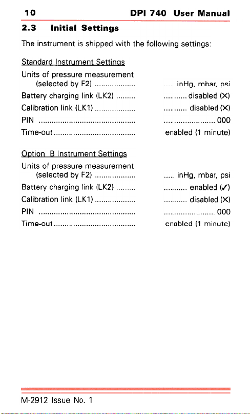
S6U!~~8S IR!~!UI £"Z
s5u!~~es 5U!MOIIO~ e~~ ~~!M pedd!~s S! ~uewnj~su! e~l
sBu!~~es ~uewnJ~sui pjepue~s
(l:J Aq pe~:>eleS)
( l)ll) )jU!1 uo!~ejq!leJ
(l:l Aq pe~:>eleS)
( l)!l) )jU!1 uo!~ejq!leJ
~uewejnseew ejnssejd ~o S~!Un
(l>ll) )jU!1 6u!6je4:> AJe~~e8
000 (X) pelqes!p (X) pelqes!p !sd 'Jeqw '6HU!
(e~nu!w ,) pelqeue
sf5u!~~es ~uewru~sul 8 UO!~aO
~uewejnseew ejnssejd to S~!Un
(l)!l) )jU!1 f5u!f5jelj:> Aje~~e8
000 (X) pelqes!p (,..) pelqeue !sd 'Jeqw '6HU!
(e!nu!w l) pelqeue
l .oN enssl ~ l6~-~
DPI 740 User Manual
3 Operation
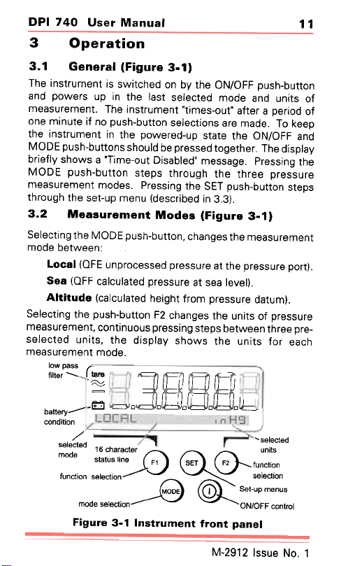
3.1 General (Figure 3-1)
The instrument is switched on by the ON/OFF push-button
and powers up in the last selected mode and units of
measurement. The instrument "times-out" after a period of
one minute if no push-button selections are made. To keep
the instrument in the powered-up state the ON/OFF and
MODE push-buttons should be pressed together. The display
briefly shows a "Time-out Disabled' message. Pressing the
MODE push-button steps through the three pressure
measurement modes. Pressing the SET push-button steps
through the set-up menu (described in 3.3).
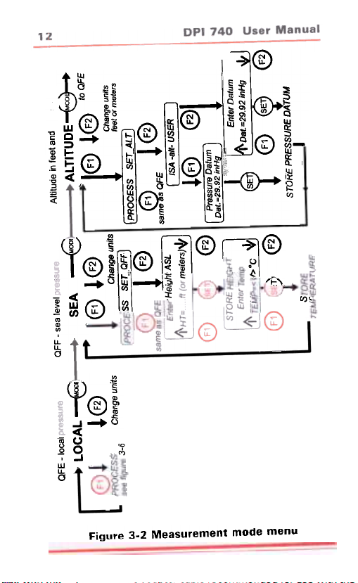
3.2 Measurement Modes (Figure 3-1)
Selecting the MODE push-button, changes the measurement
mode between:
Local (OFE unprocessed pressure at the pressure port).
Sea (OFF calculated pressure at sea level).
Altitude (calculated height from pressure datum).
Selecting the push-button F2 changes the units of pressure
measurement, continuous pressing steps between three pre-
selected units, the display shows the units for each
measurement mode.
low pass
tilter- r~ JE -f'IL
11
battery--condition
,;; v=odoa:oJdJo~ob
/ 'selected
selected 16 character units
mode
function selection seiectlon
mode seiection ON/OFF control
Figure 3-1 Instrument front panel
::=-0 ~status line F1 SET \J--- function
9 ~ Set-up menus
M-2912 Issue No.1
(0
-n
p
m
C 5.
C 01
-I ~
~ ...
~ 5
>
, -n
m
."
c
~ "'
~~~
> -
n £
O o
r-
"' m
"" 8
(I) \::)m(O
\ I:;;\ (/) ~
"'
"" m
§
~(":;;\
"'
(")+-r-
6,
"'
"'
"n
~ ~
-,-I -.rn
:io m "' ~.. ."
!.(j) ~ ~ ..i o
rn ~~ ~" C; 0 ~
~ II rn "' ~~ o
,; ~ t +-I~ +-
~
' ~..~ -i
+-(!)- m ~~ +- -iP. "'
C'
"'., 0 "'
.11~ ~m
-~ 1
~~ § ~
' -.~ (:;;'\ ~ rn
"'
-~:o ~IS'\ 8
~
oC/!
I'''
~ L I;:j\ I J~i@\!~ I @~» ~
nuew epow ~ueweJnseew z-£ eJn5!.i
DPI 740 User Manual
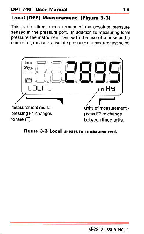
Local (QFE) Measurement (Figure 3-3)
This is the direct measurement of the absolute pressure
sensed at the pressure port. In addition to measuring local
pressure the instrument can, with the use of a hose and a
connector, measure absolute pressure at a system test point.
13
measurement mode pressing F1 changes
to tare (T)
Figure 3-3 Local pressure measurement
units of measurement press F2 to change
between three units.
M-2912 Issue No.1
 Loading...