

Page 1

User’s Guide
Shop online at
omega.com
e-mail: info@omega.com
For latest product manuals:
omegamanual.info
DPG8001
M-5103/0112
General Purpose Digital Pressure Gauge
1
Page 2

2
Page 3

OMEGAnet®Online Service: omega.com Internet e-ma il: info@omega.com
Servicing North America:
U.S.A.: Omega Engineering, Inc., One Omega Drive, P.O. Box 4047
ISO 9001 Certified
Stamford, CT 06907-0047
Toll-Free: 1-800-826-6342 Tel: (203) 359-1660
FAX: (203) 359-7700 e-mail: info@omega.co
Canada: 976 Bergar
Laval (Quebec), Canada H7L 5A1
Toll-Free: 1-800-826-6342 TEL: (514) 856-6928
FAX: (514) 856-6886 e-mail: info@omega.ca
U.S.A. and Canada: Sales Service: 1-800-826-6342/1-800-TC-OMEGA
For immediate technical or application assistance:
Customer Service: 1-800-622-2378/1-800-622-BEST
Engineering Service: 1-800-872-9436/1-800-USA-WHEN
®
®
®
Mexico: En Español: 001 (203) 359-7803 FAX: (001) 203-359-7807
info@omega.com.mx e-mail: espanol@omega.com
Servicing Europe:
Benelux: Managed by the United Kingdom Office
Czech Republic: Frystatska 184
France: Managed by the United Kingdom Office
Germany/Austria: Daimlerstrasse 26
United Kingdom: OMEGA Engineering Ltd.
ISO 9001 Certified
It is the policy of OMEGA Engineering, Inc. to comply with all worldwide safety and EMC/EMI
regulations that apply. OMEGA is constantly pursuing certification of its products to the European
New Approach Directives. OMEGA will add the CE mark to every appropriate device upon certification
The information contained in this document is believed to be correct, but OMEGA accepts no liability for any
errors it contains, and reserves the right to alter specifications without notice.
WARNING: These products are not designed for use in, and should not be used for, human applications.
Toll-Free: 0800 099 3344 TEL: +31 20 347 21 21
FAX: +31 20 643 46 43 e-mail: sales@omega.nl
733 01 Karviná, Czech Republic
Toll-Free: 0800-1-66342 TEL: +420-59-6311899
FAX: +420-59-6311114 e-mail: info@omegashop.cz
Toll-Free: 0800 466 342 TEL: +33 (0) 161 37 29 00
FAX: +33 (0) 130 57 54 27 e-mail: sales@omega.fr
D-75392 Deckenpfronn, Germany
Toll-Free: 0 800 6397678 TEL: +49 (0) 7059 9398-0
FAX: +49 (0) 7056 9398-29 e-mail: info@omega.de
One Omega Drive, River Bend Technology Centre,
Northbank Irlam, Manchester M44 5BD England
Toll-Free: 0800-488-488 TEL: +44 (0)161 777-6611
FAX: +44 (0)161 777-6622 e-mail: sales@omega.co.uk
.
3
Page 4

4
Page 5

WARNING! READ BEFORE INSTALLATION
1. GENERAL:
A failure resulting in injury or damage may be
caused by excessive overpressure, excessive
vibration or pressure pulsation, excessive instrument temperature, corrosion of the pressure containing parts, or other misuse.
Consult Omega Engineering before installing
if there are any questions or concerns.
2. OVERPRESSURE:
Pressure spikes in excess of the rated overpressure capability of the gauge may cause
irreversible electrical and/or mechanical
damage to the pressure measuring and containing elements. Fluid hammer and surges
can destroy any pressure transducer and
must always be avoided. A pressure snubber
should be installed to eliminate the damaging
hammer effects. Fluid hammer occurs when
a liquid flow is suddenly stopped, as with
quick closing solenoid valves. Surges occur
when flow is suddenly begun, as when a
pump is turned on at full power or a valve is
quickly opened.
PRESSURE SURGES:
Surges are particularly damaging to pressure
gauges if the pipe is originally empty. To avoid
pressure surges, fluid lines should remain full
(if possible), pumps should be brought up to
power slowly, and valves opened slowly. To
avoid damage from both fluid hammer and
surges, a surge chamber should be installed.
Symptoms of fluid hammer and surge’s damaging effects:
• Digital Gauge exhibits large zero offset.
• Digital Gauge pressure display remains
constant regardless of pressure
• Error code is displayed on screen.
FREEZING:
Prohibit freezing of media in pressure port.
Unit should be drained. (Mount in vertical position to prevent possible overpressure
damage from frozen media.)
3. INSTALLATION:
This procedure requires the use of a 1
1
⁄16˝
(27mm) hex wrench for tightening the instrument to the process connection. Apply
Teflon tape or a suitable sealing compound
to NPT threads of the gauge. Take using the
wrench, tighten 1 turn beyond hand-tight
or until a leak-proof seal has been
achieved.
Caution: Tightening the product by
grasping or putting a tool on the plastic
housing can cause permanent damage to
the product.
5
Page 6
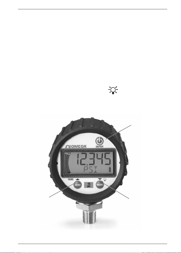
4. GENERAL INFORMATION:
Keypad:
Power On-Off / Enter
Zero / Up Arrow / Tare
Menu Selection / Down / Backlight Arrow
Key presses are short less than 0.5 seconds or long greater than 0.5 seconds
➟
|
|
ZERO
Tare
MENU
➟
6
Page 7

LCD DISPLAY:
LCD functions:
5 numerical digits for pressure display.
20 segment pressure range bar graph – each segment equals 5% of range.
Sleep and Backlight Timer symbols.
Maximum / Minimum Pressure and Tare icons.
5 character alpha-numeric digit display.
4 segment battery life indicator.
Negative pressure indicator.
7
Page 8

Note: Key presses designated as short (less
than 0.5 sec) are indicated by “
Key presses designated as long (greater than
0.5 sec.) are indicated by “
Turn the Gauge ON/OFF
|
|
Press
OFF. When initially turned ON, the display will
momentarily show all LCD segments lit, product version and full scale range; the unit will
then proceed automatically to the Measurement Mode.
key to turn instrument ON /
➟
” ICON
➟
” ICON
➟
Zero Function:
ZERO
Press
display momentarily disappears and “ZERO”
shows in alpha display, then returns to measurement mode. The pressure should now read
0. Zero value is stored in memory.
Note 1: A display message of “RLOCK” indicates that zero is more than ±5% from factory
calibration. Zeroing is not possible.
Note 2: A message of “ZLOCK” indicates that
zero lock function is activated.
. Upon release, the numeric
➟
8
Page 9

Tare Function:
Subtracts current pressure value from value
displayed in Measurement mode.
In Measurement mode, apply desired pressure
ZERO
press
, to enable the tare function. The
display will quickly flash “TARE”, then the
“TARE” icon will be displayed and the pressure
reading will blink. The unit should now read 0.
Press
able the function. The display will quickly flash
“T OFF”, then the “TARE” icon will disappear
and the pressure reading will no longer be
blinking. The unit will now return to measurement mode.
➟
ZERO
the TARE key ICON again to dis-
➟
Programming:
To enter menu mode
1. Press
2. Press
3. When desired option is reached press
4. If at any time you choose to EXIT the
Programmable Parameters:
Units of Measure:
1. In Menu mode, press
2. Choose engineering units by scrolling
3. Press
Note: Custom units programming, see page 8.
MENU
to programming mode.
grammable menu options.
|
|
to access that parameter.
➟
menu mode (or sub-menu mode) hold
MENU
➟
scroll to “UNITS”, press
,
played, “PSI, BAR, kg/cm, kPa, mPa,
FtH
O, InHg, cmHG, mmHg, customer de-
2
fined units (CUSTU)”.
|
Measurement Mode.
and release to proceed
➟
,
, to scroll through pro-
➟
. Your work will not be saved.
,
|
|
➟
, until desired unit is dis-
➟
|
to select units and return to
➟
, to
➟
.
9
Page 10

Custom Units of Measure
Allows a user to define a custom unit of measure, user must enter the full scale value of the
desired reading, which can be done as follows.
1) In Menu Mode press
“CUSTU” press
2) Select decimal point location:
The alphanumeric display shall show “SELDP”
The first screen to appear will show all digits
lit up as “5” and the rightmost decimal point
will blink (5 5 5 5.5) unless the custom units
feature had been used previously. If it had
been used, the digits and decimal point position shall correspond to the last values set.
Use the
mal point to the left or the right. Once the
decimal point is in the desired position,
|
|
press
key is released the display reads “DIGIT”.
3) Choose full scale value:
The alpha numeric display shall show “DIGIT”.
The next screen will continue to show all
digits as “5”, with the leftmost digit blinking
and the decimal point fixed in the previously
chosen position. However, if the custom
units feature has been used previously, then
the digits shall correspond to the last value.
The decimal point remains at the location
chosen in step 1. Press
change the value of the digit between 0-9.
➟
,
➟
,
select
➟
|
|
.
➟
,
keys to move the deci-
➟
to lock it in place. When the
to
Once the desired value is displayed, press
|
|
the
the next digit to the right will begin blinking.
Repeat this procedure for all 5 digits. When
the
the fifth digit flashing, the gauge will briefly
display “DONE” then return to measurement
mode and display “CUSTU” along with the
numeric readings to signify that the feature
is use.
The user can optionally exit at any point
before the enter key is pressed with
MENU
MENU
there is a menu timeout, then whatever the
user entered will be lost.
Note:The custom units feature is not available with compound pressure ranges.
Note:The bar graph uses the factory default
setting when custom units are used.
Note:The magnitude of the value entered
when using the custom units feature can
significantly increase the noise on the display, which can affect the zero and tare
functions as well as the stability of the pressure reading displayed. If required, consult
factory for recommended limitations on full
scale input.
button to lock it in place. Now
➟
|
|
is pressed and released with
➟
. If the user exits the menu by a
➟
before completing step 2 or
➟
10
Page 11

Maximum / Minimum:
Displays maximum / minimum pressure values;
this is initiated upon powering the unit or since
the values were cleared.
1. When in menu mode press
to scroll to ‘Max’ (maximum display);
this is indicated in small font to the left
of the display’s unit of measure.
2. To clear both Min and Max values, press
3. Release of this key will leave you in
ZERO
and hold
➟
Menu mode. Use
continue scrolling through the menu
options, OR hold,
to measurement mode.
Note: Clearing Minimum / Maximum
values will reflect a blank display except
for the associated Min. / Max. icon and
battery indicator.
Note:The following actions will also
clear min/max values. Power off, zero
gauge function, tare function, field calibration function, units programming,
update rate, or reset.
MENU
.
,
➟
➟
,
to
to return
➟
Timer:
Controls how long the gauge will remain pow-
|
ered ON once the Power key
1. When in menu mode press
to scroll until “TIMER” is displayed.
|
2. Press
3. Then, press
4. Press
|
.
➟
through values. “NONE” designates that
the gauge will remain ON until the
|
|
|
➟
|
power key
time. Any other value (1 min [default] / 5
min / 20 min), other than “NONE”, will
designate the duration of time this function will be in effect.
timer icon will be shown on the display
and the unit will display “DONE” then return to Measurement Mode.
Feature: Timer icon will flash 10 seconds
prior to gauge shut down.
|
is pressed.
,
,
to scroll
➟
is pressed a second
to select desired value;
➟
11
Page 12

Light:
Determines how long the back light will remain
ON after any key is pressed in Measurement or
Menu Modes (Note: The timer is reset with any
key being pressed.)
1. While in Menu mode, press
until “LIGHT” is displayed.
|
2. Press
3. Press
Note: In “PRESS” mode; factory has set 1
hour timer to save battery.
Feature: Back light indicator will blink 10 seconds prior to light shut off.
|
for timer value to appear;
“ON” refers to the back light remaining
ON at all times unit is powered ON,
“PRESS” designates that the back light
is switched on / off by briefly pressing
the backlight
dicates the back light will never be illuminated. Selecting time values, “1 MIN”
(default), “5 MIN”, “20 MIN”, will activate
the backlight symbol on the LCD display
for the designated minutes.
(display will briefly show “DONE”) and
return to Measurement Mode.
➟
MENU
➟
|
|
to select back light time
➟
,
whereas, “OFF” in-
Update:
Utilized to select the rate at which the displayed
pressure value is updated on the screen. This
function is used when rapid changes in pressure cause “flutter” in the display values;
longer intervals will reduce the update rate and
➟
“average” the readings on such applications.
1. In Menu mode, press
“UPDAT” appears.
|
2. Press
3. Press
4. Press
Note: Changing value to anything other than
1 sec may cause a slight zero offset, and it
is recommended that the gauge be fully
vented and re-zeroed before taking accurate
readings. Also, battery life will be reduced
by use of an update rate faster than 1 SEC.
|
➟
,
|
|
➟
“1 SEC” (default), “500 MSEC”, or “250
MSEC”.
briefly show “DONE”) and return to
Measurement Mode.
,
to select.
to select values for
➟
to select value (display will
until
➟
12
Page 13

Z-Lock:
Utilized to prevent inadvertent re-zeroing of the
instrument.
1. In Menu mode, press
“ZLOCK” appears.
|
2. Press
3. Press
4. Press
Note: If Z-Lock is activated, the gauge will
display “ZLOCK” if zero is attempted.
|
➟
,
OFF” (default).
|
|
will briefly show “DONE”) and return to
Measurement Mode.
➟
,
to select.
to select “L ON” or “L
➟
to select value (display
until
➟
Re-Calibration:
Provides the user the ability to field calibrate the
product. Original factory calibration is permanently retained in memory and can be recalled at
any time.
1. In menu mode press
“RECAL” appears; proceed to press
|
|
.
➟
2. Display will indicate “FACT” (factory)
“FIELD” or “NEW’ press
scroll.
3. Pressing
4. Pressing
5. Pressing “Enter” key
6. When “NEW” is displayed, press
7. Display flashes “APPLY/ REF/ PSI/ THEN/
displayed will restore values of factory
calibration.
played will restore values from latest field
calibration.
appears will enter the recalibrate mode.
upon release, the display will flash “OK/
APPLY/ REF/ PSI/ THEN/ PRESS/ ENTER/
TO/ START/ OR/ OTHER/ TO/ ABORT”.
Numeric display will read .00000. Vent
sensor to atmospheric pressure, press
|
|
display will show “WAIT” and
➟
count down from 6 seconds then briefly
display CAL then automaticly go to next
step.
PRESS/ ENTER/ TO/ START/ OR/ OTHER/
TO/ ABORT”; apply the full scale pressure
in units of psi indicated in numeric display
to gauge. Press
“WAIT” and count down from 6 seconds
then briefly display CAL then automatically go to next step.
,
|
|
while “FACT” (factory) is
➟
|
|
when “FIELD” is dis-
➟
|
|
|
|
display will show
➟
until
➟
,
when “NEW”
➟
➟
|
|
to
➟
;
13
Page 14

8. Display flashes “APPLY/ REF/ PSI/ THEN/
PRESS/ ENTER/ TO/ START/ OR/ OTHER/
TO/ ABORT”; apply the pressure indicated
in numeric display to gauge and press
|
|
display will show “WAIT” and
➟
count down from 6 seconds then briefly
display GOOD then exit into measurement mode, or
9. COMPOUND RANGE GAUGES ONLY REQUIRE ONE ADDITIONAL CALIBRATION
POINT NEAR VACUUM
10. Display flashes “APPLY/ REF/ PSI/ THEN/
PRESS/ ENTER/ TO/ START/ OR/ OTHER/
TO/ ABORT”; apply near vacuum of
–14.000 psi as indicated in numeric
|
display to gauge and press
display will show “WAIT” and count
down from 6 seconds then briefly display
“GOOD” then exit into Measurement Mode.
Note: Recalibration is allowed only if test
parameters are within ±7%. If outside this
window, the display will indicate “CAL FAIL /
INPUT PRES TOO LOW (HIGH) / PRESS ENTER
TO RETRY / PRESS OTHER TO ABORT”.
Note: “FIELD” option appears only if gauge
has been successfully field recalibrated.
|
,
➟
Graph:
Provides the user the ability to modify pressure
values dictating the minimum / maximum indications over the 20 segment bar graph.
1. In menu mode press
until “GRAPH” appears; press
2. Display will indicate “CGOFF” (custom
graph off) [default], “CG ON” (custom
graph on), or “NEWCG” (new custom
graph) press
3. To recall the last custom graph entered
when “CG ON” is displayed press
|
|
. Display will briefly show
➟
“DONE” and return to Measurement
Mode.
4. To reset bar graph to full scale range;
when “CGOFF” is displayed press
Display will briefly show “DONE”, and
➟
return to Measurement Mode.
5 To enter a new custom bar graph; when
“NEWCG” is displayed press
,
,
to scroll.
➟
|
|
➟
|
|
,
➟
➟
|
|
.
.
14
Page 15

6. To program minimum graph percentage,
the display will indicate 0 0 with the right
digit flashing, the bottom most segment
of the bar graph will flash, and the display will read “PCTFS” (percent full scale).
Press
,
,
|
|
➟
|
|
➟
to scroll to a num-
to select that num-
➟
. to scroll to a
. to select that
➟
,
. to scroll to
➟
|
|
➟
,
to select
to
➟
|
|
➟
ber 0-9. Press
ber. The left digit will now begin to flash.
Press
number 0-9.
number. The 2 digit number entered
represents the percentage of full scale
to be used as the low end of the graph
(0-99%).
7. To program maximum percentage of full
scale the display will indicate 1 0 0 with
the right digit flashing, the upper most
segment of the graph will flash, and the
display will read PCTFS (percent full
scale). Press
a number 0-9. Press
that number. The left 2 digits will now
begin to flash. Press
scroll to a number 0-10. Press
to select that number. The number entered represents the percentage of full
scale to be used as the high end of the
graph. Note: 100 is the highest and only
possible 3 digit number. If the low number is equal to or larger than the high
number, the unit will flash “REJCT”
and it will exit back into the “GRAPH”
sub-menu.
Note: Custom graph function is not available
on vacuum and compound ranges.
Note:A display message “ULOCK” indicates
that custom units are being used and bar
graph minimum and maximum are set to
the factory defaults
Reset:
Returns the product to the factory default values.Preserves field calibration. Factory calibration can be restored in the “RECAL” menu.
1. In menu mode
appears on display’s lower line;
Factory defaults pertain to units, timer,
back light, update rate, zero lock.
Display will indicate “DONE” then gauge
will switch to “OFF” condition.
,
until “RESET”
➟
|
|
.
➟
15
Page 16

Changing Batteries:
WARNING: Misuse
may cause injury or
damage. Refer to
ASME B40.100
WARNING: Misuse
may cause injury or
damage. Refer to
ASME B40.100
Grip knurled back cover and rotate counterclockwise until the ‘unlock’ icon is in alignment
with the arrow – this is on the housing at the
base of the pressure connection.
Remove cover by pulling straight back
and replace AA alkaline batteries accordingly;
ensure that the batteries are in the proper
polarity position.
For reattachment of cover, align the ‘unlock’
icon with the arrow, push cover straight in then
turn clockwise until the arrow is in
alignment with the ‘Lock’ icon.
Note: Reinstallation of the back cover may
cause the unit to read negative pressure.
This is a temporary issue as the internal case
pressure will be relieved by the case vent and
equalize with atmospheric pressure (90% of
the offset will equalize within 1 minute, the remaining 10% may take up to 5 minutes).
16
Page 17

27mm
1.063in
Hex
67mm
2.64in
50.5mm
1.99in
69.36mm
Ø
2.73in
1/4 NPT Male
Ø
40.9mm
1.61in
67.6mm
2.66in
17.5mm
.69in
Pressure Range:
Proof
Pressure: Vac-2000: 200%
% of Span 3000-5000: 150%
7500-25,000: 120%
Burst
Pressure: Vac-2000: 800%
% of Span 3000-5000: 500%
7500-25,000: 300%
Environmental Specifications:
Temperature
Storage: Batteries removed:
–20°C to 80°C (-4°F to 176°F)
Batteries installed:
–20°C to 60°C (-4°F to 140°F)
Ambient Operating:
–20°C to 60°C (-4°F to 140°F)
Process Media:
–20°C to 80°C (-4°F to 176°F)
Agency Approvals:
CE EN 61326 (1998); CE EN 61326
Annex A (Heavy Industrial)
UL/cUL- 61010-1 (pending)
RoHS compliant
Dimensions:
Assembled in U.S.A.
17
Page 18

18
Page 19

OMEGA ENGIN EE RI NG, INC. warra nts this un it to be fr ee of de fects in ma terials an d
WARRANTY/DISCLAIMER
workmanship for a period of 13 months from date of purchase. OMEGA’s WARRANTY adds an
additional one (1) month grace period to the normal one (1) year product warranty to cover
handling and shipping time. This ensures that OMEGA’s customers receive maximum coverage
on each product.
If the unit malfunctions, it must be returned to the factory for evaluation. OMEGA’s Customer
Service Department will issue an Authorized Return (AR) number immediately upon phone or
written request. Upon examination by OMEGA, if the unit is found to be defective, it will be
repaired or replaced at no charge. OMEGA’s WARRANTY does not apply to defects resulting
fro m any acti on of the purch ase r, incl uding bu t not limi ted to misha nd lin g, im prope r
interfacing, operation outside of design limits, improper repair, or unauthorized modification.
This WARRANTY is VOID if the unit shows evidence of having been tampered with or shows
evidence of having been damaged as a result of excessive corrosion; or current, heat, moisture
or vibration; improper specification; misapplication; misuse or other operating conditions
outside of OMEGA’s control. Components in which wear is not warranted, include but are not
limited to contact points, fuses, and triacs.
OMEGA is pleased to offer suggestions on the use of its various products. However,
OMEGA neither assumes responsibility for any omissions or errors nor assumes
liability for any damages that result from the use of its products in accordance with
information provided by OMEGA, either verbal or written. OMEGA warrants only
that the parts manufactured by the company will be as specif ied and free of
defects. OMEGA MAKES NO OTHER WARRANTIES OR REPRESENTATIONS OF ANY
KIND WHATSOEVER, EXPRESSED OR IMPLIED, EXCEPT THAT OF TITLE, AND ALL
IMPLIED WARRANTIES INCLUDING ANY WARRANTY OF MERCHANTABILITY AND
FITNESS FOR A PARTICULAR PURPOSE ARE HEREBY DISCLAIMED. LIMITATION OF
LIABILITY: The remedies of purchaser set forth herein are exclusive, and the total
liability of OMEGA with respect to this order, whether based on contract, warranty,
negl ige nce, in dem nif ication , s trict liability or ot her wise, shall not exceed the
purchase price of the component upon which liability is based. In no event shall
OMEGA be liable for consequential, incidental or special damages.
CONDITIONS: Equipment sold by OMEGA is not intended to be used, nor shall it be used: (1)
as a “Basic Component” under 10 CFR 21 (NRC), used in or with any nuclear installation or
activity; or (2) in medical applications or used on humans. Should any Product(s) be used in or
with any nuclear installation or activity, medical application, used on humans, or misused in
any way, OMEGA assumes no responsibility as set forth in our basic WARRANTY/ DISCLAIMER
language, and, additionally, purchaser will indemnify OMEGA and hold OMEGA harmless from
any liability or damage whatsoever arising out of the use of the Product(s) in such a manner.
Direct all warranty and repair requests/inquiries to the OMEGA Customer Service Department.
BE FO RE RET UR NI NG AN Y PRO DU CT (S ) TO OMEG A, PURC HA SE R MU ST OB TAI N AN
AUTHORIZED RETURN (AR) NUMBER FROM OMEGA’S CUSTOMER SERVICE DEPARTMENT
(IN ORDER TO AVOID PROCESSING DELAYS). The assigned AR number should then be marked
on the outside of the return package and on any correspondence.
The purchaser is responsible for shipping charges, freight, insurance and proper packaging to
prevent breakage in transit.
FOR WARRANTY
following information available BEFORE
contacting OMEGA:
1. Purchase Order number under which
the product was PURCHASED,
2. Model and serial number of the product
under warranty, and
3. Repair instructions and/or specific
problems relative to the product.
OMEGA’s po licy i s to m ake running changes, not mod el changes, whenever an improvement i s poss ible.
This affords our customers the latest in technology and engineering.
OMEGA is a registered trademark of OMEGA ENGINEERING, INC.
© Copyright 2009 OMEGA ENGINEERING, INC. All rights reserved. This document may not be copied, photocopied, re-
produced, translated, or reduced to any electronic medium or machine-readable form, in whole or in part, without the
prior written consent of OMEGA ENGINEERING, INC.
RETURN REQUESTS/INQUIRIES
RETURNS, please have the
FOR NON-WARRANTY REPAIRS,
OMEGA for current repair charges. Have the
following information available BEFORE
contacting OMEGA:
1. Purchase Order number to cover the
COST of the repair,
2. Model and serial number of theproduct, and
3. Repair instructions and/or specific problems
relative to the product.
consult
19
Page 20

Where Do I Find Everything I Need for
Process Measurement and Control?
OMEGA…Of Course!
Shop online at omega.com
TEMPERATURE
Thermocouple, RTD & Thermistor Probes, Connectors, Panels & Assemblies
⻬□
Wire: Thermocouple, RTD & Thermistor
⻬□
Calibrators & Ice Point References
⻬□
Recorders, Controllers & Process Monitors
⻬□
Infrared Pyrometers
⻬□
PRESSURE, STRAIN AND FORCE
Transducers & Strain Gages
⻬□
Load Cells & Pressure Gages
⻬□
Displacement Transducers
⻬□
Instrumentation & Accessories
⻬□
FLOW/LEVEL
Rotameters, Gas Mass Flowmeters & Flow Computers
⻬□
Air Velocity Indicators
⻬□
Turbine/Paddlewheel Systems
⻬□
Totalizers & Batch Controllers
⻬□
pH/CONDUCTIVITY
pH Electrodes, Testers & Accessories
⻬□
Benchtop/Laboratory Meters
⻬□
Controllers, Calibrators, Simulators & Pumps
⻬□
Industrial pH & Conductivity Equipment
⻬□
DATA ACQUISITION
Data Acquisition & Engineering Software
⻬□
Communications-Based Acquisition Systems
⻬□
Plug-in Cards for Apple, IBM & Compatibles
⻬□
Datalogging Systems
⻬□
Recorders, Printers & Plotters
⻬□
HEATERS
Heating Cable
⻬□
Cartridge & Strip Heaters
⻬□
Immersion & Band Heaters
⻬□
Flexible Heaters
⻬□
Laboratory Heaters
⻬□
ENVIRONMENTAL
MONITORING AND CONTROL
Metering & Control Instrumentation
⻬□
Refractometers
⻬□
Pumps & Tubing
⻬□
Air, Soil & Water Monitors
⻬□
Industrial Water & Wastewater Treatment
⻬□
pH, Conductivity & Dissolved Oxygen Instruments
⻬□
SM
M-5103/0112
 Loading...