

Page 1
Digital Pressure Gauges
DPG1000DAR Series, Low Voltage AC/DC Powered
with Dual Alarm Relays and 4 to 20 mA Output
INSTRUCTION
MANUAL
M3363/1001
Installation Precautions
Tighten/remove with wrench on hex fitting only. Do not attempt to rotate
gauge by turning housing. Use fittings appropriate for the pressure range of
the gauge. Do not apply vacuum to gauges not designed for vacuum
operation. NEVER insert objects into the gauge port or blow out with
compressed air.Permanent damage not covered by warranty will result.
Electrical Connection
NEVER connect the gauge power wires directly to 115 VAC or permanent
damage not covered by warranty will result.
The two-conductor cable at the gauge rear with the RED and BLACK leads
is for the gauge power supply. Connect to 8 to 24 VAC, 50/60Hz or 9 to 32
VDC.The gauge will operate on either AC or DC power and there is no need
to observe polarity. An unregulated power supply can be used. The supply
voltage, when within the stated ranges, has negligible effect on the gauge
calibration. Operation below 9 VDC or 8 VAC RMS may cause erratic or
erroneous readings or output.
The gauge is powered on whenever a supply voltage is applied. Warm-up
time is negligible.In normal operation the system pressure is displayed.
The color code for the 6-conductor alarm relay output cable is as follows.
SETPOINT 1 SETPOINT 2
Normally Closed (NC) BLACK Normally Closed (NC) GREEN
Common (C) RED Common (C) BROWN
Normally Open (NO) WHITE Normally Open (NO) BLUE
The shield (drain) wire is generally not needed for 4-20 mA current loops
unless long cable lengths are used in electrically noisy environments.
Operation
The gauge is on whenever a supply voltage is applied.Warm-up time for full
accuracy is negligible.In normal operation, the system pressure is displayed
on the gauge LCD.The circuitr y also compares the system pressure to two
independent setpoint levels;Setpoint 1 and Setpoint 2. These setpoint levels
may be viewed by pressing either the SP1 or SP2 buttons. Operation of the
alarm outputs is not affected by pressing SP1 or SP2.
Alarm status is easily seen on the two alarm indicator LEDs in the corner of
the SP1 and SP2 buttons. A GREEN indication is a normal or non-alar m
condition; RED is an abnormal or alarm condition.
In the standard HI/LO configuration, SP1 is configured as a HI alarm and will
provide a RED alarm indication when the system pressure exceeds the
setpoint. SP2, the LO alarm will provide a RED alar m indication when the
system pressure falls below the setpoint.
Test Button
For system setup, testing, and troubleshooting, the TEST button is provided.
The alarm outputs and the current loop may be “exercised” on demand
without the need to vary the system pressure to test devices, annunciators,
etc. connected to these outputs.
When the TEST button is pressed, the alarm relays are toggled to the
opposite state, and the 4-20 mA output is set to the “test” level, which is
indicated on the display.
The test level of the 4-20 mA output is determined by the setting of the topaccessible TEST potentiometer. To set the “test calibration” level, lift the top
calibration label and locate the “TEST” potentiometer. While pressing the
TEST button, adjust the display to the desired pressure reading that will be
output as a 4-20 mA signal. For example, on a 0 to 100 psi gauge, setting
the test level to 50.0 will give a 12 mA output whenever the TEST button is
depressed.
Setting Alarms
To access alarm SP1 and SP2 controls, lift the calibration label on the top of
unit and locate the proper potentiometer as indicated by the gauge rear
label.This label can be reused many times.
Pressing SP1 or SP2 will switch the display to show and allow adjusting of
the corresponding alarm setpoint.
To adjust alarm Setpoint 1, press and hold the SP1 button.When holding the
SP1 button, the display will show the current setting for Setpoint 1. Turn the
top-accessible Setpoint 1 control. Repeat the procedure by pressing and
holding the SP2 button to adjust Setpoint 2.
It is allowable to set the LO alarm to a higher pressure than the HI alarm.
Normal (Failsafe) vs. Reverse Action - Alarm configuration is set at the
factory at time of manufacture. Standard is a Normal (Failsafe) action HI/LO
configuration where SP1 is the HI alarm and SP2 is the LO alarm. Gauges
with HI/HI, LO/LO and reverse action relay configurations are also available.
With the Normal or Failsafe configuration, the alarm output relays will be
CLOSED (relay energized) for a clear or non-alarm condition and OPEN
(relay not energized) for an alarm condition. This is primarily for users who
desire an alarm condition should the gauge lose power. “Normally closed”
and “normally open” designations refer to standard relay terminology; i.e.,
the relay contact status with the relay coil not energized.
With the Normal (Failsafe) configuration, when in a green or non-alarm
condition, the relay will be energized so that continuity can be expected
between the common and normally open leads. In a red or alarm condition,
the relay will be open (not energized), so that continuity can be expected
between the common and normally closed leads.
With the Reverse acting alarm configuration, the relays will be open (not
energized) in the non-alarm condition and closed for the alarm condition. In
this case, continuity can be expected from common to normally closed in the
green (non-alarm) condition and from common to normally open in the red
(alarm) condition. This configuration can be used if a non-alarm condition is
desired when the gauge power is shut off.
Alarm Deadband - The alar m circuit setpoints have built-in deadbands, also
known as hysteresis, of 1% of span as standard.This means, for example,
the deadband is approximately 1 psi in a 0 to 100 psi gauge.
This deadband serves to eliminate output oscillation or “chatter” of the
alarms due to minor fluctuations in pressure. If, for example, the system
pressure in a 0-100 psi system is 40.0 psi, and Setpoint 1 is set to 50.0 psi
(HI alarm), the alarm indication will trip if the pressure exceeds 50.0 psi.
After the HI alarm has tripped, pressing the SP1 button will show that the
alarm indication will “release” at 1 psi lower (approximately 49 psi).
Deadband is set at the factory to 1% but other deadbands can be configured
at the factory where the application requires.
Contact Rating and Protection - The contacts of the alarm relays are rated
at 1A/24VDC or 0.5A/115VAC maximum with non-inductive loads. Using
mechanical relay contacts above their rating, or with large inductive loads,
will shorten their useful life. In circuits other than low-level switching or pilot
duty, the user should consider whether external contact protection such as
snubber networks or arc suppression networks are required to protect the
contacts. When switching higher electrical loads, the alarm relay should be
used to drive an external contactor or solid state relay of sufficient capacity.
In addition, no internal fusing is included in the gauges. The circuit external
to the gauge alarm outputs should be fused by the user in applications
where good design practice dictates.
Page 2
1
/4" NPT
2.88"
3.38"
0.75"
1.65"
Turn at
hex
fitting
only!
0.75"
Two 3 ft long, 4conductor & 6
conductor
22 AWG shielded
cables
SPECIFICATIONS
Ranges & Resolution
30.0 inHg vacuum, ±15.00, 3.00, 5.00, 15.00 psig
30.0, 100.0, 199.9, 300, 500, 1000, 3000, 5000 psig
Absolute reference:15.00, 100.0 psia
Optional Units
Most engineering units such as kPa, atm, bar,
mbar, inHg, mmHg, inH2O, ftH2O, torr, kg/cm2,
cmH
2
O, oz/in
2
Display (type, size, update rate)
Ranges up to 1999: 3
1
/
2 digit LCD,
1
/
2" digit height
3000 & 5000 psi ranges: 4 digit LCD, 0.4" H digits
3 readings per second nominal display update
Accuracy (linearity, hysteresis, repeatability)
±0.25% of full scale or better, ±1 least significant
digit
Temperature Stability(rel. to 77°F or 25°C)
±1% FS for offset & span, 32 to 158°F (0 to 70°C)
typical
±2% FS for offset & span, 32 to 158°F (0 to 70°C)
typical for 3 and 5 psi ranges
Alarm Deadbands (hysteresis)
1% of of full scale
Alarm Outputs
Dual form C (SPDT) relay contacts
Individual Setpoint 1 and Setpoint 2 settings via
top-accessible multiturn potentiometers
HI/LO alarm configuration standard
Relay contacts rated 1A/24VDC, 0.5A/115VAC
maximum, non-inductive
Alarm Indicators
Bicolor (red/green) LEDs on front panel
Alarm Response Time
100 milliseconds typical
Test Function
Front panel TEST button toggles SP1 and SP2
alarm status and 4-20 mA output to test level,
independent of pressure input to allow testing of
system operation.
Retransmission Output
4-20 mA DC true analog output, 50 milliseconds
typical response time.Output drive (compliance)
determined by power source.
Power
DC 9 to 32 VDC, or AC 8 to 24VAC 50-60Hz
1.0 watt max.power consumption
Storage Temp:–40 to 203°F (–40 to 95°C)
Operating Temp:–4 to 185°F (–20 to 85°C)
Compensated Temp:32 to 158°F (0 to 70°C)
Weight (approximate)
Gauge: 9 ounces, shipping weight: 1 pound
Housing
Extruded aluminum case, light gray epo xy powder
coated
Black polycarbonate cover, front and rear gaskets
Electrical Connection
3 ft long, 4-conductor 22AWG cable for power
and 4-20 mA output.
3 ft long, 6-conductor 22AWG alarm relay cable
Pressure/Vacuum Connection & Material
1
/
4
" NPT male.All wetted parts are 316SS
Overpressure & Burst
5000 psig for 3000 psig range
7500 psig for 5000 psig range
All others 2x rated pressure minimum
Burst: 4x rated pressure minimum or 10,000 psi,
whichever is less
Using the 4-20 mA Output
The 4-20 mA output is driven by the transducer rather than the display and
thus is a true analog output.The output is filtered to improve noise immunity
and thus has a response time of about 50 msec.
The power supply (–) lead is tied to the 4-20 mA output ground. Therefore
the DC supply (–) lead should be considered common with regard to the 420 mA output (–) or ground connection.
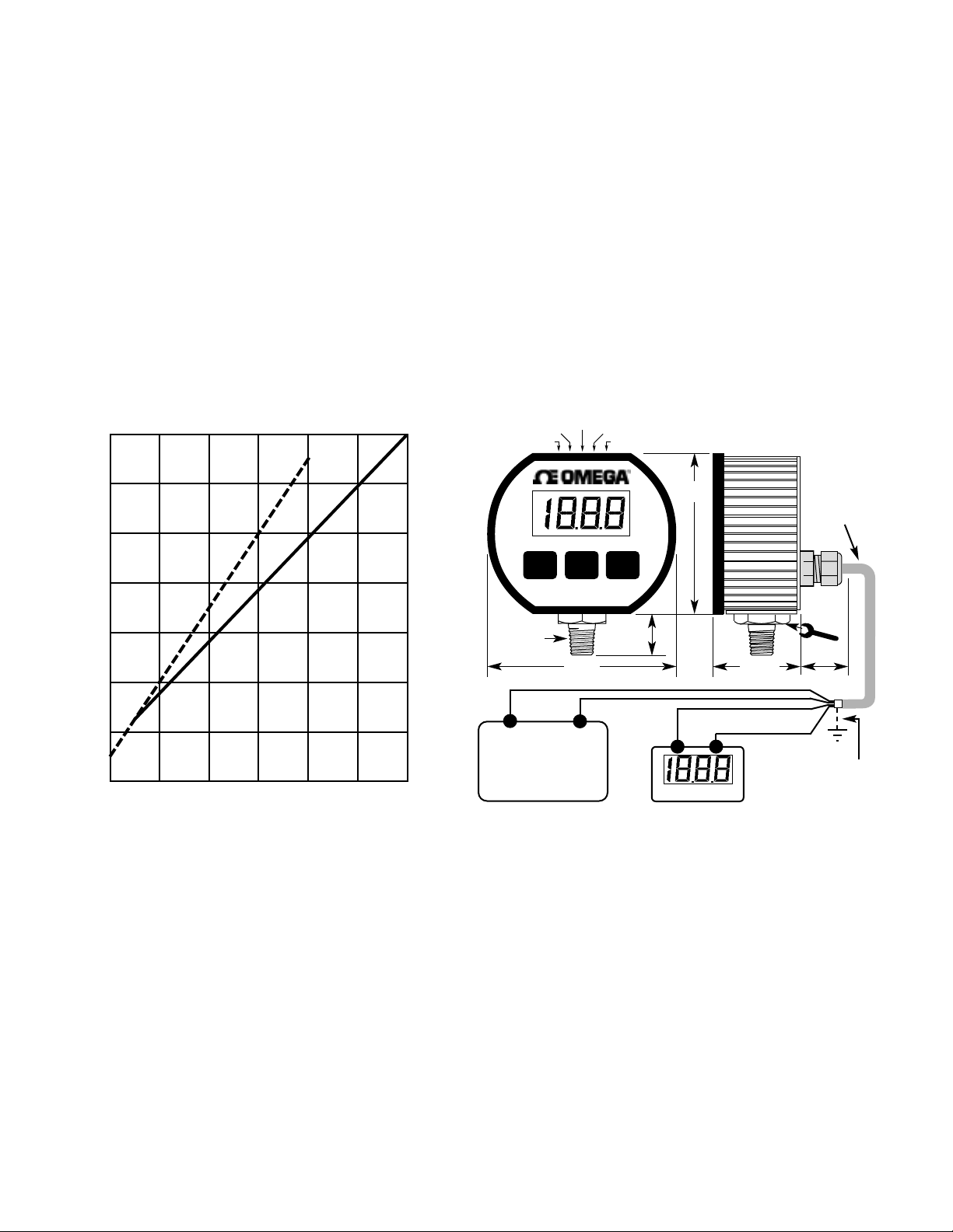
Be sure to observe the output compliance (voltage drive) capabilities of the
gauge. The compliance, and therefore the maximum loop resistance the
output can drive, is a function of the supply voltage to the gauge. Consult
the graph below for maximum loop resistance vs. supply voltage.Too large a
loop resistance will cause the gauge output to “limit” or saturate before
reaching its full 20 mA output.
Calibration
These gauges are factory calibrated and normally do not require
recalibration before being put into service. If calibration is required, lift
calibration label on the top of unit to access the Zero and Span controls.this
label is designed to be reused many times.
For GAUGE reference units the setting of the Zero control is correct when
the gauge reads zero, with the “–” sign occasionally flashing, when the
pressure port is open to the ambient. Zero calibration must be done before
span calibration is attempted. Since the calibration potentiometers are non-
interactive, gauge reference units may be rezeroed without affecting the
span.
Span calibration should only be done when a pressure reference of known
accuracy is available. The calibration equipment accuracy should be better
than 4 times the accuracy of the gauge. Zero calibration must be done
before span calibration. Record readings at three to five points over the
range of gauge and adjust span control to minimize error and meet
specifications.
Calibration of ABSOLUTE reference units is more difficult and is not
recommended in the field, unless the user has access to equipment
required to calibrate absolute-reference units, such as vacuum generation
and atmospheric pressure measurement equipment.
Gauges can be returned to Omega Engineering for recalibration. NIST
traceability is available.
The DPG1000DAR has internal controls that adjust the “agreement”
between the displayed value and the 4-20 mA loop current. These are
carefully set at the factory and should not normally be adjusted. Should the
user feel this adjustment is necessary, the display zero/span must be
accurately set first. Then, after removing the rear cover, the “loop zero” and
“loop span” controls may be trimmed for 4.00 mA of loop current at the low
end of the range, and 20.00 mA at the high end of the range, respectively.
Accurate pressure generation and measurement, and current measurement
equipment are required to successfully complete this calibration.
OMEGA Engineering Inc./Made in USA
TEST
SP1 SP2
1400
1200
1000
800
600
400
200
0
Max Loop Resistance (Ohms)
8 121620242832
Supply V oltage
Voltage Compliance for 4-20 mA Output
PSIG
DC
AC
Gauge power supply
9-32 VDC
or
8-24 VAC 50/60 Hz
(–)BLACK
(+)RED
(+)WHITE
(–)GREEN
Remote device
Optional
shield
connection
Zero SP2
Span
Test
SP1
See "Electrical Connections"
for relay wiring
Page 3

DPG1000-PS Optional Power Supply Kit
The optional power supply kit includes a UL and CSA listed
115 VAC (50/60 Hz) wall-mount power supply with U.S. style
2-prong plug. Output is 12 VDC at 200 mA and is intended
for gauges that accept DC power. The power supply’s twoconductor wire is approximately 6 feet long and has plain
wire ends. Also included is a moisture resistant connector to
allow easy hookup without having to strip wires.Use a pair of
pliers to snap connector onto wires.
Note: A higher voltage power supply may be required for your current loop.
See instructions for loop resistance and compliance voltage
1N Alarms, Hi/Lo Normal (Failsafe) Action
TEST
SP1
SP2
Span
Zero
Top View of Gauge
Potentiometers
Front
Condition Below SP Above SP Power Failure
Relay coil Energized Not energized Not energized
NC to Common Open Continuity Continuity
NO to Common Continuity Open Open
Alarm LED Green Red off
SP1, High Alarm
Condition Above SP Below SP Power Failure
Relay coil Energized Not energized Not energized
NC to Common Open Continuity Continuity
NO to Common Continuity Open Open
Alarm LED Green Red off
SP2, Low Alarm
2N Alarms, Hi/Hi Normal (Failsafe) Action
Condition Below SP Above SP Power Failure
Relay coil Energized Not energized Not energized
NC to Common Open Continuity Continuity
NO to Common Continuity Open Open
Alarm LED Green Red off
SP1, High Alarm
Condition Below SP Above SP Power Failure
Relay coil Energized Not energized Not energized
NC to Common Open Continuity Continuity
NO to Common Continuity Open Open
Alarm LED Green Red off
SP2, High Alarm
3N Alarms, Lo/Lo Normal (Failsafe) Action
Condition Above SP Below SP Power Failure
Relay coil Energized Not energized Not energized
NC to Common Open Continuity Continuity
NO to Common Continuity Open Open
Alarm LED Green Red off
SP2, Low Alarm
Condition Above SP Below SP Power Failure
Relay coil Energized Not energized Not energized
NC to Common Open Continuity Continuity
NO to Common Continuity Open Open
Alarm LED Green Red off
SP1, Low Alarm
1R Alarms, Hi/Lo Reverse Action
SP1, High Alarm
SP2, Low Alarm
2R Alarms, Hi/Hi Reverse Action
SP1, High Alarm
SP2, High Alarm
3R Alarms, Lo/Lo Reverse Action
SP2, Low Alarm
SP1, Low Alarm
Condition Below SP Above SP Power Failure
Relay coil Not energized Energized Not energized
NC to Common Continuity Open Continuity
NO to Common Open Continuity Open
Alarm LED Green Red off
Condition Above SP Below SP Power Failure
Relay coil Not energized Energized Not energized
NC to Common Continuity Open Continuity
NO to Common Open Continuity Open
Alarm LED Green Red off
Condition Below SP Above SP Power Failure
Relay coil Not energized Energized Not energized
NC to Common Continuity Open Continuity
NO to Common Open Continuity Open
Alarm LED Green Red off
Condition Below SP Above SP Power Failure
Relay coil Not energized Energized Not energized
NC to Common Continuity Open Continuity
NO to Common Open Continuity Open
Alarm LED Green Red off
Condition Above SP Below SP Power Failure
Relay coil Not energized Energized Not energized
NC to Common Continuity Open Continuity
NO to Common Open Continuity Open
Alarm LED Green Red off
Condition Above SP Below SP Power Failure
Relay coil Not energized Energized Not energized
NC to Common Continuity Open Continuity
NO to Common Open Continuity Open
Alarm LED Green Red off
Alarm Configuration Options
Model number: DPG1000DAR_____________________
Serial number:
Location:
Date recieved:
Date put in service:
Next calibration due:
Wiring Summary Potentiometers
4 Conductor Cable
Power Connection,DC 9 to 32 VDC,or AC 8 to 24 VAC 50-60Hz
RED (+) BLACK (–)
Current Loop Connection, 4-20 mA Output
WHITE (+) GREEN (–)
6 Conductor Cable
SETPOINT 1 Connections SETPOINT 2 Connections
Normally Closed(NC) BLACK Normally Closed(NC) GREEN
Common (C) RED Common (C) BROWN
Normally Open (NO) WHITE Normally Open (NO) BLUE
Page 4

It is the policy of OMEGA to comply with all worldwide safety and EMC/EMI regulations that apply.
OMEGA is constantly pursuing certification of its products to the European New Approach Directives.
OMEGA will add the CE mark to every appropriate device upon certification.
The information contained in this document is believed to be correct but OMEGA Engineering, Inc.accepts
no liability for any errors it contains, and reserves the right to alter specifications without notice.
WARNING:These products are not designed for use in, and should not be used for, patient connected applications.
WARRANTY/DISCLAIMER
OMEGA ENGINEERING, INC.warrants this unit to be free of defects in materials and workmanship for a period of 13 months from date
of purchase.OMEGA’s Warranty adds an additional one (1) month grace period to the normal one (1) year product warranty to cover
handling and shipping time.This ensures that OMEGA’s customers receive maximum coverage on each product.
If the unit should malfunction, it must be returned to the factory for evaluation. OMEGA’s Customer Service Depar tment will issue an
Authorized Return (AR) number immediately upon phone or written request. Upon examination by OMEGA, if the unit is found to be
defective it will be repaired or replaced at no charge.OMEGA’s WARRANTY does not apply to defects resulting from any action of the
purchaser, including but not limited to mishandling, improper interfacing, operation outside of design limits, improper repair, or
unauthorized modification. This WARRANTY is VOID if the unit shows evidence of having been tampered with or shows evidence of
being damaged as a result of excessive corrosion;or current, heat, moisture or vibration; improper specification; misapplication; misuse
or other operating conditions outside of OMEGA’s control. Components which wear are not warranted, including but not limited to
contact points, fuses, and triacs.
OMEGA is pleased to offer suggestions on the use of its various products.However, OMEGA neither assumes responsibility for any omissions
or errors nor assumes liability for any damages that result from the use of its products in accordance with information provided by OMEGA,
either verbal or written. OMEGA warrants only that the parts manufactured by it will be as specified and free of defects.OMEGA MAKES NO
OTHER WARRANTIES OR REPRESENTATIONS OF ANY KIND WHATSOEVER, EXPRESSED OR IMPLIED, EXCEPT THAT OF TITLE,
AND ALL IMPLIED WARRANTIES INCLUDING ANY WARRANTY OF MERCHANTABILITY AND FITNESS FOR A PARTICULAR
PURPOSE ARE HEREBY DISCLAIMED.LIMITATION OF LIABILITY:The remedies of purchaser set forth herein are exclusive and the total
liability of OMEGA with respect to this order, whether based on contract, warranty, negligence, indemnification, strict liability or otherwise, shall
not exceed the purchase price of the component upon which liability is based.In no event shall OMEGA be liable for consequential, incidental
or special damages.
CONDITIONS: Equipment sold by OMEGA is not intended to be used, nor shall it be used: (1) as a “Basic Component”under 10 CFR
21 (NRC), used in or with any nuclear installation or activity; or (2) in medical applications or used on humans. Should any Product(s)
be used in or with any nuclear installation or activity, medical application, used on humans, or misused in any way, OMEGA assumes
no responsibility as set forth in our basic WARRANTY/ DISCLAIMER language, and additionally, purchaser will indemnify OMEGA and
hold OMEGA harmless from any liability or damage whatsoever arising out of the use of the Product(s) in such a manner.
RETURN REQUESTS / INQUIRIES
Direct all warranty and repair requests/inquiries to the OMEGA Customer Service Department. BEFORE RETURNING ANY
PRODUCT(S) TO OMEGA, PURCHASER MUST OBTAIN AN AUTHORIZED RETURN (AR) NUMBER FROM OMEGA’S
CUSTOMER SERVICE DEPARTMENT (IN ORDER TO AVOID PROCESSING DELAYS). The assigned AR number should then be
marked on the outside of the return package and on any correspondence.
The purchaser is responsible for shipping charges, freight, insurance and proper packaging to prevent breakage in transit.
FOR W
ARRANTY RETURNS, please have the following
information available BEFORE contacting OMEGA:
1. P.O. number under which the product was PURCHASED,
2. Model and serial number of the product under warranty, and
3. Repair instructions and/or specific problems relative to the
product.
FOR NON-W
ARRANTY REPAIRS,
consult OMEGA for current
repair charges.Have the following information available
BEFORE contacting OMEGA:
1. P.O.number to cover the COST of the repair,
2. Model and serial number of product, and
3. Repair instructions and/or specific problems relative to
the product.
OMEGA’s policy is to make running changes, not model changes, whenever an improvement is possible. This affords our customers the latest in technology and
engineering.
OMEGA is a registered trademark of OMEGA ENGINEERING, INC.
© Copyright 2001 OMEGA ENGINEERING, INC. All rights reserved. This document may not be copied, photocopied, reproduced, translated, or reduced to any
electronic medium or machine-readable form, in whole or in part, without prior written consent of OMEGA ENGINEERING, INC.
Servicing North America:
USA: One Omega Drive, P.O. Box 4047
ISO 9001 Certified Stamford CT 06907-0047
TEL: (203) 359-1660 FAX: (203) 359-7700
e-mail: info@omega.com
Canada: 976 Bergar
Laval (Quebec) H7L 5A1
TEL: (514) 856-6928 FAX: (514) 856-6886
e-mail: canada@omega.com
For immediate technical or application assistance:
USA and Canada: Sales Service: 1-800-826-6342 / 1-800-TC-OMEGA
®
Customer Service: 1-800-622-2378 / 1-800-622-BEST
®
Engineering Service: 1-800-872-9436 / 1-800-USA-WHEN
®
TELEX: 996404 EASYLINK: 62968934 CABLE: OMEGA
Mexico: Tel: (001) 800-826-6342 FAX: (001) 203-359-7807
En Espan˜ol: (001) 203-359-7803 e-mail: espanol@omega.com
info@omega.com.mx
OMEGAnet®On-Line Service Internet e-mail
www.omega.com info@omega.com
Servicing Europe:
Benelux: Postbus 8034, 1180 LAAmstelveen, The Netherlands
Tel: +31 (0)20 6418405 FAX: +31 (0)20 6434643
Toll Free in Benelux: 06 0993344
e-mail: nl@omega.com
Czech Republic: Rudé armády 1868,73301 Karviná
TEL: +420 (0)69 6311899 FAX: +420 (0)69 6311114
Toll Free in Czech Rep.: 0800-1-66342
e-mail: czech@omega.com
France: 9, rue Denis Papin, 78190 Trappes
TEL: +33 (0)130 621 400 FAX: +33 (0)130 699 120
Toll Free in France: 0800-4-06342
e-mail: france@omega.com
Germany/Austria: Daimlerstrasse 26, D-75392 Deckenpfronn, Germany
TEL: +49 (0)7056 3017 FAX: +49 (0)7056 8540
Toll Free in Germany: 0800 TC OMEGA
SM
e-mail: germany@omega.com
United Kingdom: P.O. Box 7, Omega Drive,
ISO 9002 Certified Irlam, Manchester,
M44 5EX, United Kingdom
TEL: +44 (0)161 777 6611 FAX: +44 (0)161 777 6622
Toll Free in England: 0800 488 488
e-mail: sales@omega.co.uk
 Loading...