

Page 1
Made in China
DPF708, DPF808 Series
Flow Totalizers
Page 2
Page 3

CONTENTS
1. MODEL CONFIGURATION ……………...……………............................................................................................................ 3
2. TECHNICAL SPECIFICATION ……………………………………………………………………………………………………......5
3 PARAMETERS AND SETTINGS……………….….……………………………………….…………………………………………7
3.1 PARAMETER LOCK (LOC) AND FIELD PARAMETERS........................................................................................................7
3.2 THE FULL PARAMETER TABLE ...........................................................................................................................................7
4. WIRING AND REAR TERMINALS LAYOUT ………………………………………..……………………………………………. 17
5. DISPLAYS AND OPERATIONS……………………………………..………………………………………………………........... 19
5.1 FRONT PANEL DESCRIPTION …………………………………...…………………………………………………………………19
5.2 DISPLAY AND OPERATION………………………………………………………………………………………………………...20
5.2.1 DISPLAY STATUS SWITCH……………………………………………………………………………………………………….….20
5.2.2 PARAMETER SETTING………………….……………..…………………………………………………………………………….21
5.2.3 MANUALLY RESET THE ACCUMULATED VALUE…………………………………………………………………………….….21
5.2.4 POWER FAILURE MEMORY FOR ACCUMULATED VALUE………………………………………………...…………………..21
5.3 BATCH CONTROL………………………………………………………………………………………………………………..….22
Page 4

6. CONFIGURATION EXAMPLES…………………………………………..……………………………………………………..……22
7. CALCULATION PRINCIPLE OF THE INSTRUMENT……………………………………………………………………………24
7.1 CALCULATION PROCEDURE OF FLOW COMPENSATION…………………………………………………………………….24
7.2 RELEVANT COMPENSATION FORMULA AND TABLE………………………………………………………………………...25
7.2.1 TEMPERATURE-PRESSURE COMPENSATION FOR COMMON AIR……………………………………………………….25
7.2.2 TEMPERATURE COMPENSATION FOR COMMON LIQUID……………………………………………………….……………25
7.2.3 COMPENSATION FOR SATURATED STEAM AND SUPERHEATED STEAM……………………………………………….25
8. SYMBOL DESCRIPTIONS………………………………………………………………………………………………………….25
Page 5

1. MODEL CONFIGURATION
Model
DPF718(*)-(***)-(****)-(*****)
DPF728(*)-(***)-(****)-(*****)
DPF738(*)-(***)-(****)-(*****)
DPF748(*)-(***)-(****)-(*****)
DPF818(**)-(***)-(****)-(*****)
DPF828(**)-(***)-(****)-(*****)
DPF838(**)-(***)-(****)-(*****)
DPF848(**)-(***)-(****)-(*****)
* Specify input code from Flow Input Options table below
** Specify input code (For Temperature or Pressure Compensation) from Flow Input Options table below
*** Specify batch control code from Batch Output Options table below
**** Specify alarm code from Alarm Options table below
***** Low voltage power supply option (-LV)
Description
FLOW TOTALIZER 1/4 DIN
FLOW TOTALIZER 1/4 DIN, with Light Bar
FLOW TOTALIZER 1/8 DIN VERT
FLOW TOTALIZER 1/8 DIN HORIZ
FLOW TOTALIZER 1/4 DIN, with Temperature or Pressure compensation
FLOW TOTALIZER 1/4 DIN, with Light Bar, with Temperature or Pressure compensation
FLOW TOTALIZER 1/8 DIN VERT, with Temperature or Pressure compensation
FLOW TOTALIZER 1/8 DIN HORIZ, with Temperature or Pressure compensation
Page 6

Flow Input Option (*)
Option Type
For frequency signal flow sensor, with12VDC/50mA power supply -F
For 0-5V/1-5V voltage signal flow sensor, with 12VDC/50mA power supply -V
For 4-20mA/0-20mA current signal flow sensor, with 12VDC/50mA power supply -C
Flow Input Options
Page 7

Flow Input Option (**) (For Temperature or Pressure Compensation)
Option Type (For Temperature or Pressure Compensation) Input Option
Temp. and Pressure Input: Flow Input
Dual input available, suit for two-wire
re-transmitter
Thermocouple, RTD or mV signal input; or
0-5V or 1-5V pressure sensor
For frequency signal flow sensor, with12VDC/50mA
power supply
For 0-5V/1-5V voltage signal flow sensor, with
12VDC/50mA power supply
For 4-20mA/0-20mA current signal flow sensor, with
12VDC/50mA power supply
For frequency signal flow sensor, with12VDC/50mA
power supply
For 0-5V/1-5V voltage signal flow sensor, with
12VDC/50mA power supply
For 4-20mA/0-20mA current signal flow sensor, with
12VDC/50mA power supply
-FC
-VC
-CC
-FT
-VT
-CT
Page 8

Batch Output Option (***)
Option Type Output
Relay -R1
DC SSR driver -DC1
Alarm Options (****)
Option Type Alarm Output
Relay -R2
DC SSR driver -DC2
Low voltage power supply option (*****)
Option Type
24V AC/DC, 50/60 Hz -LV
100~240VAC, 50/60Hz Blank
Page 9

2. TECHNICAL SPECIFICATION
Frequency units: Hz
Temperature units:
Pressure units: MPa
Accumulation time:
Fixed at 1 hour for flow accumulation, and the unit can be freely set for batch control.
Momentary flow unit:
Different units can be set, like M3/hour, kg/hour, ton/hour. The decimal point can be freely set.
Accumulation flow unit:
The unit and resolution is the same as momentary flow
℃
Page 10

Flow input type:
Frequency : 0-3200Hz, the low level signal is 0-1V, the high level signal is 3-24V Voltage
Voltage: 1-5V, 0-5V
Current and two wire
re-transmitter
4-20mA, 0-20mA, 0-10mA
Temperature input type:
Thermocouple
RTD
Voltage 0-20mV, 20-100mV, 0-100mV, 0-1V, 0.2-1V
Current 4-20mA, 0-20Ma
Two-wire re-transmitter Directly connect to two wire re-transmitter.
K (0-999℃), E (0-800℃), J (0-999℃)
Pt100 (-200 ~ +600℃)
Page 11

Pressure input type:
Voltage : 1-5V, 0-5V
Current 4-20mA, 4-20mA
Two-wire re-transmitter Directly connect to two wire re-transmitter.
Measurement accuracy:
±0.2% FS, for temperature 、pressure 、frequency 、momentary flow without temperature- pressure compensation.
Temperature drift:
≤0.01%FS /℃ (typical value is 50ppm/℃)
Momentary flow retransmission accuracy:
14 bit output resolution and 0.2%FS
Page 12

Temperature/pressure compensation method (For DPF818,DPF828,DPF838,DPF848 only):
General gas: Temperature- pressure compensation (Calculate by equation for ideal gases)
Saturated steam:
Saturated steam: Pressure compensation (Refer to table , absolute pressure range: 0.1-3.2Mpa)
Superheated steam:
General liquid: Only use temperature compensation, PA is compensation factor.
Temperature compensation (Refer to table , temperature range:100℃-276℃)
Temperature- pressure compensation (Refer to table , temperature range: 150℃-590℃ pressure
range: 0.1-22Mpa)
Calculation accuracy for temperature- pressure compensation:
The calculation error is less than 0.3% FS, and after compensation, the overall error is less than 0.5% FS.
Accumulation accuracy:
The error is less than 0.01%FS (just the frequency error produced by crystal oscillator).
Page 13

Electromagnetic compatibility (EMC) :
±4KV/5KHz according to IEC61000-4-4; 4KV according to IEC61000-4-5
Isolation withstanding voltage:
Between power, relay contact or signal terminal ≥2300VDC; between isolated electroweak terminals ≥600VDC
Power supply :
100 ~ 240VAC, -15%, +10% / 50-60Hz; 120 ~ 240VDC; or 24VDC/AC, 15%, +10%.
Power consumption:
≤5W
Operating Ambient :
Temperature -10~60℃; Humidity ≤90%RH
Page 14

3. PARAMETERS AND SETTINGS
3.1 Parameter Lock (Loc) and Field Parameters
In order to protect important parameters from being modified by mistake, but also offer enough flexibility for field control, parameter
lock (Loc) and field parameters are introduced.
The parameters need to be displayed and modified in the work field are called Field Parameters. The set of field parameters is a
subset of the full parameter set, and can be freely chosen by the user . User can select up to 8 filed parameters through parameter
EP1~EP8.
Loc can authorize different security privilege. For details, please read the description of parameter “Loc” in the full parameter table.
Setting Loc=808, and then pressing to confirm, can enter the full parameter table and modify all parameters.
Page 15

3.2 The Full Parameter Table
Code Name Description
FHIA
FLoA
FdF
CHIA
CLoA
High limit alarm for
momentary flow
Low limit alarm for
momentary flow
Alarm hysteresis for
momentary flow
High limit alarm for
temperature
Low limit alarm for
temperature
Alarm is triggered when momentary flow >FHIA; alarm is released when momentary flow
<FHIAF-FdF; Alarm action output can be defined by parameter ALP.
Alarm triggered when momentary flow<FLoA; alarm released when momentary
flow>FLoA+FdF
Avoid frequent alarm on-off action because of the fluctuation of PV
Alarm is triggered when temperature >CHIA; alarm is released when temperature
<CHIAF-1.0℃;
Alarm triggered when temperature <CLoA; alarm released when temperature >CLoA+1.0
℃
Setting
Range
0 ~9999
units
0 ~ 9999
units
-199.9 ~
999.9℃
Page 16

PHIA
PLoA
ALP
High limit alarm for
pressure
Low limit alarm for
pressure
Alarm output allocation
Alarm is triggered when pressure >PHIA; alarm is released when pressure
<PHIAF-0.010MPa;
Alarm triggered when pressure <PLoA; alarm released when pressure > PLoA+0.010MPa
ALP defines the alarm output allocation. Its value is calculated as below:
ALP=Ax1+Bx2+Cx4+Dx8+Ex16+Fx32
A=0, FHIA alarm triggers AL1 relay; A=1, FHIA triggers AL2.
B=0, FLoA alarm triggers AL1 relay; B=1, FLoA triggers AL2.
C=0, CHIA alarm triggers AL1 relay; C=1, CHIA triggers AL2.
D=0, CLoA alarm triggers AL1 relay; D=1, CLoA triggers AL2.
E=0, PHIA alarm triggers AL1 relay; E=1, PHIA triggers AL2.
F=0, PLoA alarm triggers AL1 relay; F=1, PLoA triggers AL2.
1.999 ~
30.00MPa
0~63
Page 17

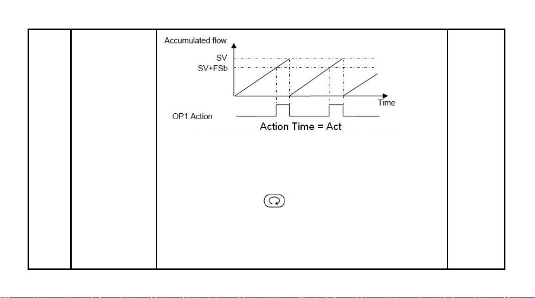
Act
Relay action time for
batch control
Act=0, batch control function is disabled, and the instrument is only used for flow
accumulation.
Act=1-254, when the flow accumulation for batch control gets to SV+FSb (setpoint+offset),
OP1 relay (the relay installed in OUTP socket) will be triggered. Parameter “Act”
determines the latching time of the relay, the unit of which is 0.48s. After the latching time
passed, OP1 relay will be released, the accumulator for batch control will be reset to zero,
and the accumulation start again.
You can set parameter FSb to make it equal to the flow accumulation value during the relay
latching time, this will make the actual flow accumulation equal to setpoint value SV.
0~255(x
0.48s)
Page 18
When Act=255, the relay latching time is infinitely long, then after the action of batch
control relay OP1 is triggered, it will not terminate or reset automatically. At this time, you
can terminate or reset the batch control action, i.e., release the OP1 relay and start the
next batch control, by pressing key or triggering an external discrete input signal.
Page 19

FSb
Batch control offset
When the instrument is used for batch control, the relay’s actual action point is “SV+FSb”.
“FSb” is usually set to be a negative value. For example, if there is a 5 units of flow during
the relay switching time, you can set FSb=-5 to make the actual control value equal to SV
value. That is to say, if SV=1000, then when the 4 digits flow accumulation value reach
995, AL2 relay is triggered immediately, and make the actual control value just equal to
1000.
-1999 ~
+9999
Page 20

SPE
Accumulation rate for
batch control
When the instrument is used for flow accumulator, the time unit in accumulation rate is
fixed, i.e., the time unit is 1 hour. When the instrument is used for batch control, you can
modify parameter “SPE” to change the accumulation rate time. The formula is as the
following:
Accumulation rate time= SPE x0.48 (seconds)
Normal setting is like the following:
SPE=7500, represents that the time unit of the accumulation rate is 1 hour. SPE=750,
represents that the time unit is 0.1 hour.
SPE=125, represents that the time unit is 1 minute. In order to get good control accuracy,
you can properly set parameter SPE according to the action period of batch control.
For example, provided that the momentary flow keep 100.0 unchanged, the flow
accumulation value will increase by 100.0 after 1 hour if you set the accumulation rate time
to be 1 hour (SPE=7500), and the flow accumulation value will increase by 100.0 after 1
minute if you set the accumulation rate time to be 1 minute (SPE=125). The smaller the
parameter SPE, the faster the flow is accumulated.
25~7500
(x0.48s)
Page 21

Sn
Input Specification
(temperature / pressure
/ flow)
This table is for DPF718,DP728, DPF738 and DPF748 only
Flow Input Option Code ( * )
-F (Frequency) 0
-V (0~5V / 1~5V) 1
-C (0~20mA / 4~20mA) 2
The following table is for (DPF818,DP828, DPF838 and DPF8480) only
For Temperature / Pressure Compensation type. The hundred’s place (SN_3) 、ten’s place
(SN_2) and unit’s place (SN_1) of parameter. Sn represents the signal input specification
for temperature 、pressure and flow respectively.
SN ---- [Temp.] [Pressure] [Flow]
| | |
| | |
| | Sn_1=0, Flow input signal is pulse frequency.
SN
0~999
Page 22

| | Sn_1=1, Flow input signal is 0-5V/0-20mA.
| | Sn_1=2, Flow input signal is 1-5V/4-20mA.
| |
| |
| Sn_2=0, no pressure signal input.
| Sn_2=1, Pressure signal is 0-5V, at terminals 17+, 18-.
| (For FT, VT and CT input option only).
| Sn_2=2, Pressure signal is 1-5V, at terminals 17+, 18-.
| (For FT, VT and CT input option only).
| Sn_2=3, Pressure signal is 4~20mA or two wires transmitter.
| (For FC, VC and CC input option only).
|
|
Sn_3=0, no temperature signal input.
Sn_3=1, K type thermocouple (For FT, VT and CT input option only).
Page 23

Sn_3=2, E type thermocouple (For FT, VT and CT input option only).
Sn_3=3, J type thermocouple (For FT, VT and CT input option only).
Sn_3=4, N type thermocouple (For FT, VT and CT input option only).
Sn_3=5, Cu 50 (For FT, VT and CT input option only).
Sn_3=6, Pt100 (For FT, VT and CT input option only).
Sn_3=7, Temperature signal input is 0~1V at terminals 19+, 18-
(For FT, VT and CT input option only).
Sn_3=8, Temperature signal input is 0.2~1V, at terminals 19+, 18-
(For FT, VT and CT input option only).
Sn_3=9, Temperature signal is 4~20mA or two wires transmitter.
(For FC, VC and CC input option only).
For Example: The temperature-pressure compensation is needed and the temperature
sensor type is Pt100, the pressure input signal is 1~5V, the high scale of frequency input.
Sn= 620
Page 24

CdIP
Co
CdIH
Temperature point
position
Reference working
temperature of the flow
sensor
Temperature range
It only works for customized compensation method.
CdIP=0, the temperature display format is 0000;
CdIP=1, the temperature display format is 000.0;
CdIP=2, the temperature display format is 00.00;
CdIP=3, the temperature display format is 0.000.
Parameter Co is used to set the reference working temperature of the
flow sensor. If Sn-3=0 is set, and parameter bC is set to have temperature compensation,
at this time, the system will assume that the temperature is fixed at Co for compensation
calculation.
When the temperature input is a linear voltage or current signal such as 0.2-1V 、0-1V 、
4-20mA and 0-10mA, this parameter is used to define the measurement range of
temperature transmitter (the maximum temperature minus the minimum temperature). The
low scale of temperature transmitter is defined by parameter “CSc”.
0~3
-199.9 ~
+999.9℃
0~999.9℃
Page 25

When temperature input is RTD or thermocouple, parameter CSc is used to make input
shift to compensate the error produced by sensor itself. Fox example, provided input signal
keep unchanged, if when parameter “CSc” is set to 0.0 , the temperature measurement of
the instrument is ℃ 101.0 , then when parameter “Sc” is set to ℃ -1.0℃, the temperature
CSc
Temperature input
offset / Temperature
lower limit
measurement display will be 100.0℃
When the temperature input is a linear voltage or current signal, parameter CSc is used to
define the low scale of temperature transmitter. Fox example, if the measurement range of
a temperature transmitter is 0-400℃, then you can set like the following: CSc=0.0,
CdIH=400.0; if the measurement range of a temperature transmitter is 100-400℃, then you
can set CSc=100.0 and CdIH=300.0
-199.9 ~
999.9℃
Page 26

PdIP
Po
Pressure point position
Reference working
pressure
It only works for customized compensation method.
PdIP=0, the pressure display format is XXXX;
PdIP=1, the pressure display format is XXX.X;
PdIP=2, the pressure display format is XX.XX;
PdIP=3, the pressure display format is X.XXX.
This is gauge pressure. For absolute pressure, you should add 0.1013Mpa. When the set
value is larger than 9.999Mpa, the display resolution will change from 0.001Mpa to 0.01Mpa
automatically.
0~3
0 ~
30.000MPa
Page 27

PA
Atmospheric pressure
at the instrument site /
temperature
compensation factor
If pressure compensation is needed, PA represents the atmospheric pressure at the
instrument site. The unit is Mpa. The atmospheric pressure above sea level is set to be
0.101Mpa. If the temperature transmitter has a zero shift error, you can also use this
parameter to make a input correction.
When bC=5, the instrument has temperature compensation only. This case suits for general
liquid measurement which need temperature compensation. At this time, PA represents
temperature compensation factor. The setting range is from –1.999 to +9.999, and the unit
is %/℃. The instrument compensation density formula is as the following:
ρB/ρo=1+PA×(C-Co)/100
ρB is the density after compensation, ρo is the density at reference temperature of Co, C is
the actual temperature of liquid, Co is the reference temperature.
0~1.000MPa
or %/℃
Page 28

PdIH
PSc
Cut
Frd
Range of pressure
input
Scale low limit of
pressure input
The cut off ratio for
small flow signal
Scale high limit of
frequency input
When the flow input is frequency signal, the pressure input can be 0-5V 、1-5V 、0-10mA or
4-20mA. When the set value is larger than 9.999Mpa, the display resolution will change
from 0.001Mpa to 0.01Mpa automatically.
Generally, it is set to 0. Or according to sensor measurement range to set.
For linear input: Cut=0.0~50.0%, if flow input is less than range multiply cut off ratio (FdIH x
Cut), then the flow input is ignored or set to be zero.
For frequency input: Cut=0.0~50.0Hz, if flow input is less than “Cut”, then the flow input is
ignored or set to be zero.
It represents the scale high limit of frequency input (range), and is used to calculate the flow
range for frequency input. You can set it to be a value which is a little larger than the
maximum frequency in actual use.
0 ~
30.000MPa
-1999 ~
9999MPa
0~50.0% Or
0~50Hz
5~3200Hz
Page 29

FdIP
Decimal point place for
flow display
FdIP=0, the flow display is like XXXX
FdIP=1, the flow display is like XXX.X
FdIP=2, the flow display is like XX.XX
FdIP=3, the flow display is like X.XXX
When the instrument is used for temperature-pressure compensation, the flow display value
will exceed 9999, at this time, the decimal point place will move to right by 1 digit
automatically.
When the flow display is like XXXX (FdIP=0), and if the flow display value exceeds 9999,
then the display mode will change to XX.XX because it is impossible for the decimal point
place to move to right by 1 digit. Therefore in the application where the flow display value
will exceed 9999, you had better set FdIP=3 to make the flow display be like X.XXX, and the
unit can be changed from Kg to Ton or from Ton to Kton.
0~3
Page 30

FdIH
FSc
FdL
Flow input range
Input shift for
momentary flow
Digital filter strength for
flow signal
FdIH represents the momentary flow value when the input voltage or current is at the
maximum value, or the input frequency equals to the range high limit Frd. It is the range of
flow transmitter. It is provided that the pressure and temperature equals to reference
working pressure Po and reference working temperature Co respectively. For detail
calculation of FdIH, please refer to latter description.
It is used to make input shift to compensate the error produced by sensor itself. The Input
shift value equals to FSc x 0.005%. This parameter is only used to make input shift for
analog flow input, it takes no action for frequency input.
It is used to set the digital filter strength for flow signal. When a large value is set, the flow
input is stabilized but the responsibility at the time is deteriorated. In the application where
there is a small frequency input and the retransmission output is needed, you can properly
set this parameter to make the fluctuated frequency value change into stable current
retransmission output.
When FdL=0, the filter function is disabled.
10 ~ 9999
flow units
-1000 ~
2000
(x 0.005% of
range)
0~20
Page 31

CF
Function selection
CF=A×1+C×4+D×8+E×16+F×32+G×64+Hx128
For frequency input, the instrument takes no square root extraction.
For linear voltage or current input, parameter CF.A is used to define square root extraction
like the following:
A=0, there is no square root extraction for linear input signal and temperature-pressure
compensation density ratio.
A=1, the instrument takes square root extraction for linear input signal and
temperature-pressure compensation density ratio. You should set like this for differential
transmitter. But for frequency input, this setting takes no effect.
A=2, there is no square root extraction for input signal, but the instrument takes square root
extraction for temperature-pressure compensation density ratio. No matter what types of
input, linear voltage/current or frequency, this setting takes effect.
C=0, the accumulation continues when the flow input is over range.
C=1, the accumulation stops when the flow input is over range.
D=0, the display mode 3 、4 and 5 will switch back to mode 2A and 2B automatically after 30
0~255
Page 32

seconds.
D=1, there is no automatic switching back, so the instrument can keep displaying
temperature or pressure.
E=0, For batch control, OP1 relay contact is normal open. When the flow accumulation
value is greater than the setpoint, the relay contact will be closed.
E=1, For batch control, OP1 relay contact is normal close. When the flow accumulation
value is greater than the setpoint, the relay contact will be open.
F=0, communication protocol is version V5.X.
F=1, communication protocol is version V6.0.
G=0, The flow input is linear input signal.
G=1, With flow meters the relationship between the flow rate and the output signal may
deviate from an ideal curve –linear or squared. The instrument is able to compensate for this
deviation with an additional non-linear table (see latter text for details).
H=0, display the frequency or flow before temperature-pressure compensation.
H=1, no display the frequency or flow before temperature-pressure compensation.
Page 33

bC
Temperature-
pressure
compensation mode
bC=0, no compensation.
bC=1, temperature-pressure compensation for common air (calculation with equation for
ideal gases).
bC=2, temperature compensation for saturated steam (Refer to table, temperature range:
100℃~276℃).
bC=3, pressure compensation for saturated steam (Refer to table, absolute pressure range:
0.1~3.2Mpa).
bC=4, temperature-pressure compensation for superheated steam (Refer to table, 150℃~
590℃, 0.1~22Mpa).
bC=5, temperature compensation for common liquid, PA is compensation factor.
bC=6, use temperature difference to calculate heat, it equals to the temperature difference
times the flow value.
bC=8, for common air with saturated vapor. Temperature- pressure compensation, deduct
vapor by looking up the table according to temperature. Other settings beyond 6 are used
for special compensation calculation.
0~9999
Page 34

FoH
IoL
IoH
Addr
bAud
Flow range for
retransmission
output
Low scale for
retransmission
output current
High scale for
retransmission
output current
Communication
address
Communication baud
rate
It is momentary flow range for retransmission output. For example, if you set like:
FoH=5000, IoL=40, IoH=200, then when the momentary flow value is great than or equals to
5000, the retransmission output current is 20mA, and when the momentary flow value
equals to 0, the retransmission output current is 4mA.
It is used to define the low scale for retransmission output current. If a retransmission output
of 0-10mA is needed, you can set IoL=0. If a retransmission output of 4-20mA is needed,
you can set IoL=40.
It is used to define the high scale for retransmission output current. If a retransmission
output of 0-10mA is needed, you can set IoH=100. If a retransmission output of 4-20mA is
needed, you can set IoH=200.
In the same communication line, different instrument should be set to different address.
The instrument can communicate with host computer. It is recommended to be 9600.
10~9999 flow
unit
0~60
(x 0.1mA)
0~220
(x 0.1mA)
0~100
0~19200
Page 35

CLn
FLJH
Zero reset counter
The most significant
4 digits of flow
accumulator
When the instrument is used as flow accumulator, each time you make zero reset operation
from key pad or when the 8 digits accumulator exceeds 99999999, the accumulation value
will be reset to zero, and parameter CLn will increase by 1. Parameter CLn is for display
only, modification by operator is impossible.
When the instrument is used for batch control, not matter that the 4 digits batch accumulator
is zero reset manually or automatically, parameter CLn will not change. Only when the 8
digits total acculator combined by FLJH and FLJL exceeds 99999999, parameter CLn will
increase by 1. Therefore CLn 、FLJH and FLJL can be combined together to be a 12 digits
accumulator.
When CLn exceeds 9999, it will reset to zero automatically.
It is the most significant 4 digits of the 8 digits flow accumulator. Parameter FLJH is for
display only, cannot be modified by operator.
0~9999
0~9999
Page 36

FLJL
Loc
The least significant
4 digits of flow
accumulator
Parameter lock
It is the least significant 4 digits of the 8 digits flow accumulator. Parameter FLJL is for
display only, modification by operator is impossible. When the instrument is used for batch
control, you can get total flow accumulation value by reading parameter CLn 、FLJH and
FLJL. Since this parameter is updated every 3 minutes, so the reading accumulation value
maybe less than the real accumulation value.
Loc=0, modification of field parameters is allowed, and zero reset operation for flow
accumulation from key pad is also allowed.
Loc=1, modification of field parameters is allowed, but zero reset operation for flow
accumulation from key pad is not allowed.
Loc=2, modification of field parameters is not allowed, but zero reset operation for flow
accumulation from key pad is allowed.
Loc=3, modification of field parameters is not allowed, and zero reset operation for flow
accumulation from key pad is not allowed either.
Loc=808, modification of all parameters is allowed, and zero reset operation for flow
accumulation from key pad is also allowed. If parameter set is locked, setting Loc=808 can
0~9999
0~9999
Page 37

unlock temperately. After the temperate parameter changing, Loc will reset to zero again.
Now you can set Loc to 808 again to unlock permanently.
1 to 8 field parameters can be defined by parameters EP1to EP8. If the number of the field
EP1~
EP8
Field parameter
definition
parameters is less than 8, the first idle EP parameter should be set to “nonE”.
You can define field parameters and Loc to change operation style. For example, user often
modify the parameters FHIA and CHIA, Then the EP paramters and Loc should be set as
below: Loc=0, EP1=FHIA, EP2=CHIA, EP3=none
nonE and all
parameter
codes
Compensated with an additional linearization table
With flow meters the relationship between the flow rate and the output signal may deviate from an ideal curve –linear or squared. The
instrument is able to compensate for this deviation with an additional linearization.
The linearization table enables up to 60 pairs of values to be entered.
Set parameter Loc=3698, you will enter into the configuration of the linearization table (If former setting of parameter Loc is 808, at first
you need to escape from the parameter setting status by setting Loc=0, and then enter into the parameter setting status again by setting
Loc=3698.)
Page 38

A00 function code. It is not used temporarily, and should be set to be 0.
A01 input type. For instrument, the input type is set by parameter Sn, so this parameter should be set to be 0.
A02 the low scale of input signal. The range is from –20000 to +20000.
A02= the low scale of input signal*20000/the range of amplifier. For example, if the flow input is 0-5V (the range of amplifier is 5V), and
you expect to make compensation to get 1-5V input, you can set like: A02=1 x 20000/5=4000.
A03 input signal span. For example, for 1-5V input, the span is 5-1V=4V, and you can set like: A03=4 x 20000/5=16000.
A04 the span between adjacent sample points. The number of sample points=A03/A04. If only one sample point needed, then
A04=A03.
d00 the starting point of linearization table. It is the output of linearization table when the input signal is A02. You can set it to be 0.
d01 the first output point of linearization table. It is the output of linearization table when the input signal is A02+A04.
Page 39

d02~d60: 2~60 output values of linearization table.
Sn-1 should be set according to the description in the parameter table. The instrument will process the input signal with offset,
extraction and small signal cut function. If linearization compensation is needed, set G of parameter CF to 1, and set the above
linearization compensation table.
Page 40

4. WIRING AND REAR TERMINALS LAYOUT
Page 41

Note:
1. Fin, Cin and Pin indicate the input interface of flow, temperature and pressure.
2. 0-5V or 1-5V signal for pressure is inputted from terminals 17+ and 18-.
3. The compensation wires for different kinds of thermocouple are different, and should be directly connect to the terminals. When
the internal auto compensation mode is used connecting the common wire between the compensation wire and the terminals will
cause measurement error.
4. Terminal 16 “V+” indicate the positive polar of internal 24V power output.
5. For 2 wires flow retransmitter, terminal 16(+), terminal 14(-)
Page 42

Select thermocouple reference junction compensation mode by using different wiring mode:
Reference junction compensation is needed junction for thermocouple input. Instrument supply good reference junction compensation
for thermocouple input through 4 different compensation modes selective using software configuration and different external wiring.
Page 43

5. DISPLAYS AND OPERATIONS
5.1 Front Panel Description
1
○
Upper display window, displays PV, parameter code, etc.
○2 Lower display window, displays SV, parameter value, or alarm
message
○3 Setup key, for accessing parameter tableland conforming
parameter modification.
○4 Data shift key
○5 Data decrease key
○6 Data increase key
○7 10 LED indicators: MAN and PRG is non-applicable, MIO, OP1,
OP2, AL1, AL2, AU1, AU2 individually indicates the input/output
action of the according modules; COMM
Page 44

5.2 Display and Operation
5.2.1 Display status switch
Press key to switch between different display mode.
Mode ○1 (FL) : Displays monetary flow.
Page 45

Mode ○2 A : When the instrument works for flow accumulation (parameter Act=0), display
8 digital accumulated flow.
Mode ○2 B : When the instrument works for batch control (parameter Act=1~255), the upper window display 4 digital accumulated flow,
and the lower display window
displays ○4 digit control setpoint.
Mode ○3 (F) : When the flow input is voltage or current signal, it displays the momentary
flow before the compensation; when frequency signal, it displays the frequency.
Mode ○4 (C) : Displays temperature.
Mode ○5 (P) : Displays pressure.
If automatic display switching function is set (refer to parameter CF), the display mode ○1 , ○3 , or ○5 will automatically switch to display
mode ○2 A or ○2 B after 30 seconds. If the temperature-pressure compensation function is disabled (parameter bC=0) and the flow input
signal is not frequency, then the upper display window will not display the flow before compensation.
If the instrument has no temperature or pressure signal input, then the temperature or pressure will not be displayed.
Page 46

5.2.2 Parameter Setting
Page 47

5.2.3 Manually reset the accumulated value
When the instrument is used for flow accumulation (Act=0) and the parameter Loc=0 or 808, pressing ▲ and holding for about 2
seconds can reset the 8 digit accumulated value to zero.
After each zero reset operation, the accumulation time will be reset to zero also, and the zero reset counter Cn will increase by 1. The
zero reset counter Cn recorders total zero reset times in the instrument.
When the flow accumulation value exceed 99999999, the accumulated flow will be automatically reset to zero, and Cn increases by 1.
If the accumulated value has not been manually reset, then Cn and the 8 digit accumulated value can work together as a 12 digit
accumulator.
Cn and accumulated value can’t be manually modified. Cn will be automatically reset to zero after it is greater than 9999.
When the instrument works for batch control (Act=1 ~ 255), manually reset operation is disabled.
Page 48

5.2.4 Power failure memory for accumulated value
The accumulated value is saved in memory, and will not be lost even when power failure.
5.3 Batch control
The instruments can work for flow accumulation and batch control. (set parameter Act=1~255).
When the instrument is used as batch control, there is a 4 digit accumulator for batch control. When the accumulated value reach the
control setpoint (SV+FSb), a relay in OUTP socket will be triggered (OP1 light on). The accumulated value will be reset to zero
automatically after the relay is released. The latching time of the relay can be set to any length. If it is set to infinite long, it need to
release the relay from external operation. In batch control mode, the parameters CLn, FLJH and FLJL can work together as a 12 digital
accumulator for calculating the total accumulated value.
When the parameter Act, the latching time for batch control relay, is set to 255, it means the time is infinite long, and after the relay is
triggered, it will not be automatically released. At this situation, pressing key can release the relay, and make it available for next
control action.
In mode 2B, pressing ◄ 、▲ or ▼can modify batch control setpoint SV.
Page 49

6. CONFIGURA TION EXAMPLES
To decide the reference pressure Po or the reference temperature Co, you should select the most commonly used pressure or
temperature (or the highest pressure or temperature from re-transmissier) to avoid too big compensation factor (density ratio). If the
flow value after compensation is too small, the resolution will be low and the error will be increased. If the flow value after compensation
is greater than 25000, overflow will take place.
When the instrument is specially used for flow accumulation, the time unit for momentary flow must be “hour” to assure that the
accumulated flow and the momentary flow have the same engineering unit. When the instrument is used for batch control, you can set
parameter “SPE” to change the time unit. The numerical value of parameter “FdIH” (ignoring the decimal point) should be between 500
and 9999. You had better set it to be a four-digit number to guarantee good resolution and precision. At the same time, you should
make sure that the momentary flow after compensation be less than 25000, otherwise overflow will take place and the excess will be
ignored.
When decide on the decimal point place (parameter “FdIP”), you should keep in mind that is described as below:
When the instrument is used for temperature-pressure compensation, the flow display value maybe exceed 9999, at this time, the
decimal point place will move to right by 1 digit automatically. So, if the flow display is like XXXX (FdIP=0), and the flow value exceeds
9999, then the display mode will change to XX.XX, because it is impossible for the decimal point place to move to right by 1 digit.
Page 50

Therefore the application for flow display, you had better set FdIP=3 to make the flow display be like X.XXX, and the unit can be
changed from Kg to Ton or from Ton to Kton.
Example 1:
Use a vortex flow transmitter to measure the flow of saturated steam, temperature compensation is needed and the temperature sensor
type is Pt100, the flow factor (K) of the transmitter is 3200, and the reference temperature is 200℃ (if the flow transmitter supplier
doesn’t provide a reference temperature, you can use the most commonly used temperature as a reference temperature). By looking up
3
table, you can get that the liquid density ρo =7.864Kg/M
flow at the reference temperature is 2T/h . The time unit for the momentary flow is “hour”, and you can set like below ( t=3600):
Sn=600 (temperature input type is Pt100, no pressure, flow input signal is frequency)
Co=200.0℃
Frd=flow range x K / (ρo x t) = 2000 x 3200 / (3600 x 7.864) = 226.07 (Hz)
Since Frd should be an integer, and also some extra space should be saved to the flow range, Frd can be set to 190.
FdIH= t×Frd×ρo /K=3600×190×7.864/3200=1680.93 (Kg/h)=1.681 (T/h)
FdIP=3
bC=2 (saturated steam, temperature compensation)
when the reference temperature is 200℃. The required range of accumulated
Page 51

Example 2:
A vortex flow transmitter is used to measure the mass flow or standard volumetric flow of compressed air. The temperature-pressure
compensation is needed and the temperature sensor type is Pt100, the pressure input signal is 1~5V, the high scale of frequency input
(Frd) from the transmitter is 300Hz, the flow factor (K) of the transmitter is 2000, the reference temperature is 50 ℃, and the reference
pressure is 1Mpa (if the flow transmitter supplier doesn’t provide a reference pressure, you can use the most commonly used pressure
or the high limit scale as a reference temperature). By calculation, you can get that the liquid density ρo at the reference temperature
and pressure is 11.882Kg/ m
standard condition (0℃ and 1 standard atmosphere) the air density ρs is 1.293Kg/ m
Sn=620
Co=50.0(℃)
Po=1.000(MPa)
PA=0.101(MPa)
Frd=300(Hz)
bC=1 (temperature-pressure compensation for common air, calculation with equation for ideal gases)
If it is needed to display and accumulate mass flow, you can set FdIH and dIP like below:
3
. The absolute pressure of air equals to the reference pressure plus 0.1013Mpa, i.e., 1.1013Mpa. At
3
. You can set like below:
Page 52

FdIH= (3600×Frd×ρo) / K = 3600×300×11.882/2000=6416Kg/h=6.416(T/h)
FdIP=3
If it is needed to display and accumulate standard volumetric flow, you can set FdIH and dIP like below:
3
FdIH=6416/ρs=6416/1.293=4962(m
/h),FdIP=0
If the momentary flow after compensation may exceed 9999, it is recommended to set like below:
3
FdIH=4.962(K m
/h ),FdIP=3
Example 3:
Use orifice plate to measure flow of superheated steam, with differential pressure input, temperature-pressure compensation is needed.
When the pressure is 5Mpa and the temperature is 400℃, the maximum momentary flow is 100T/h (input voltage is 5V). You can set
like below:
Co=500(℃); Po=5.000(MPa)
PA=0.101(MPa)
FdIH=100.0(T/h)
FdIP=1(the decimal point is at ten’s place)
bC=4 (superheated steam).
Page 53

7. CALCULATION PRINCIPLE OF THE INSTRUMENT
7.1 Calculation procedure of flow compensation
Step 1:
Get the flow F before compensation at first
F=V×FdIH + FSc for voltage/current input
Or
F=f×FdIH/Frd + FSc for frequency or pulse input
Among which:
V is voltage or current signal input, the numerical value is 0-100%. Before used for calculation, V is processed by the functions of small
signal cut off and square root/no square root according to the settings of parameter Cut and CF.
f is frequency signal input. The unit is Hz. Before used for calculation, signal preprocessing like small signal cut off is done on f
according to the setting of parameter Cut.
F get from above formula is the flow at reference pressure Po and reference temperature Co.
Page 54

Step 2:
Get temperature-pressure compensation density ratio ρB/ρo according to the setting of parameter bC. If the compensation need to look
up table (for example, saturated steam and superheated steam), you can get the actual density ρB by looking up table using actual
temperature C and actual pressure P, and you can also get the reference density ρo by looking up table using reference temperature
Co and reference pressure Po. Then you can get temperature-pressure compensation density ratio ρB/ρo.
Step 3:
Get compensated flow FB
FB=F × ρB / ρo if no square root is need for temperature-pressure compensation density ratio.
FB=F× if square root is need for temperature-pressure compensation density ratio.
Page 55

7.2 Relevant compensation formula and table:
7.2.1 Temperature-pressure compensation for common air
When bC=1, the instrument make compensation for common air using the equation for ideal gases. The formula is below:
ρB / ρo =(P+PA)×(Co+273.2)/((Po+0.1013)×(C+273.2))
Among which:
ρB is the actual density after temperature-pressure compensation.
ρo is reference density at reference temperature Co and reference pressure Po.
P is actual pressure (gauge pressure).
C is actual temperature (℃).
PA is atmosphere pressure at factory site, 0.1013 MPa is one standard air pressure.
Page 56

7.2.2 Temperature compensation for common liquid
No compensation is needed for liquid. To get high precision, temperature compensation can be taken (bC=5). PA is temperature
compensation factor, the range is from –1.999 to +9.999, the unit is %/℃. The formula is below:
ρB / ρo =1+PA×(C-Co)/100
Among which:
ρB is the actual density.
ρo is reference density at reference temperature Co.
C is actual temperature (℃).
Co is reference temperature.
7.2.3 Compensation for saturated steam and superheated steam
For steam, the compensation calculation by looking up table has a higher precision. You can look up relevant material for the
relationship between steam density and temperature & pressure.
Page 57

8. SYMBOL DESCRIPTIONS
Symbol Description
Input specification setting is incorrect
Or
orAL
Input wiring is disconnected/ thermocouple problem
Or
Short circuited
EErr
8888
IC Software error
IC Software error
Page 58

Page 59

M-4547/0607
 Loading...