

Page 1
1
⁄8 DIN VERSATILE PROCESS MONITORS
CONFIGURABLE
OMEGA®DP2000 digital indicator/controllers introduce a new world
DP2000 Series
DP2000-S, 1⁄8 DIN meter, $360,
shown smaller than actual size.
Starts at
$
265
Complete with
Input Board
of versatility. A universal 1⁄8 DIN case houses each meter. Choose any
combination of display type (LED or LCD), operating power, input type
and range, analog output, and digital or control outputs. OMEGA will
supply a fully burned-in and tested DP2000.
DP2000 ORDERING GUIDE
To Order (Specify Model Number)
MODEL NO.
DESCRIPTION
DP2
000XA. Motherboards
0 LED; 120 Vac (50/60 Hz) $225
1 LCD; 120 Vac (50/60 Hz) 275
2 LED; 240 Vac (50/60 Hz) 225
3 LCD; 240 Vac (50/60 Hz) 275
4 LED; 9 to 32 Vdc, isolated 370
5 LCD; 9 to 32 Vdc, isolated 420
6 LED; 5 Vdc 355
7 LCD; 5 Vdc 405
8 LED; 24 Vac 255
9 LCD; 24 Vac 305
A LED; 26 to 56 Vdc, isolated 365
B LCD; 26 to 56 Vdc, isolated 415
0 1 mV/count (supplied on all units) N/C
1 0 to 5 Vdc $70
2 0 to 10 Vdc 70
3 0 to 1 mA (internally driven) 70
4 4 to 20 mA (internally driven) 70
5 4 to 20 mA (externally driven) 115
6 4 to 20 mA (isolated) 135
0 None N/C
1 Dual setpoint, 10 A relay (SPDT) $165
2 Proportional 4 to 20 mA 225
3 Proportional/time proportioning, 2 A relay 295
4 Parallel BCD, isolated 155
5 Single setpoint, 10 A relay (SPDT) 125
Accessory
B. Analog Outputs
C. Control Outputs
D. Signal Conditioner Inputs
A(*)
DC voltage $40
B(*)
DC current 40
C(*)
AC AVG voltage 65
D(*)
AC AVG current 65
E(*)
Process signal with 15 Vdc excitation 80
F(*)
AC RMS voltage 100
G(*)
AC RMS current 100
H(*)
Frequency/rate 85
J(*)
Type J thermocouple 80
K(*)
Type K thermocouple 80
T(*)
Type T thermocouple 100
P(*)
Process signal 60
M(*)
RTD, 1° resolution 90
R(*)
RTD, 0.1° resolution 100
S(*)
Strain gage 135
Refer to the specification pages D-82 and D-83 for information about
*
PRICE
signal conditioners.
DP2000-J1, $305, with
TJ36-ICSS-116G-12,
transition joint probe, $28,
shown smaller than actual size,
visit omega.com/tj36-icin
Model No. Price Description
DPP-5 $5251⁄8 DIN panel punch
Comes complete with operator’s manual.
Ordering Example: DP2000-A2, LED 120 Vac, 1 mV/count, DC voltage between
-1.999 and 1.999 V, $225 + 40 = $265.
D-79
Page 2
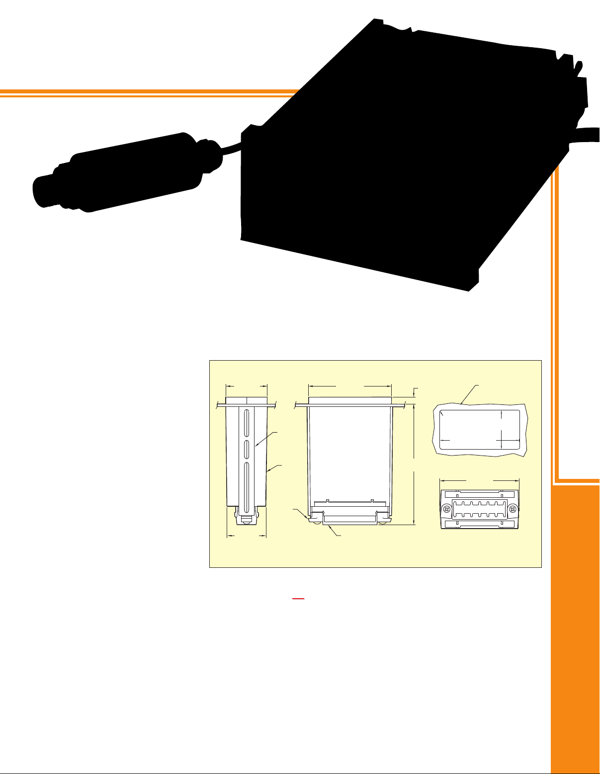
48.0
(1.89)
SLIDE
RETAINER
CASE
CLAMP
RING
45.0
(1.77)
TERMINAL BLOCK COVER
Terminal block cover and bezel
not shown for clarity. Clamp rings
rotated and slide retainers removed
as shown for installation.
91.9
(3.62)
139.6 (5.50)
MAX
92.00 +0.81/-0.00
(3.622 +0.032/0.000)
45.00 +0.61/-0.00
(1.772 +0.024/-0.000)
R
1.5
(0.06)
4 PLCS
PANEL THICKNESS:
6.4 (0.25) MAX
0.8 (0.03) MIN
7.9
(0.31)
MAX
96.0
(3.78)
VERSATILE PROCESS MONITORS
DP2401-P, $595, shown smaller
than actual size, with PX209, $195,
pressure transducer, sold separately,
see page B-90.
SPECIFICATIONS
Conversion
Technique: Auto-zero,
dual slope, average value
Signal Integration Period:
100 ms, nominal
Reading Rate: 2.5/s, nominal
Display
LED: Red, 14.2 mm (0.56"), 7-segment
LCD: 12.7 mm (0.50"), 7-segment
Range: 0 to ±1999
Overload Indication: 3 least-significant
digits blanked, “1” or “-1” displayed
Power
AC Models: 120/240 Vac
(10 to 15%), 49 to 440 Hz or
24 Vac (10 to 15%)
DC Models: 5 Vdc ±5%, 9 to 32 Vdc
or 26 to 56 Vdc
Common Mode
Voltage: 1500 Vp test
(354 Vp per IEC spacing).
Rejection (DC to 60 Hz): 120 dB
Environmental
Operating Temperature: 0 to 60°C
(32 to 140°F)
Storage Temperature: -40 to 85°C (-40 to 185°F)
Humidity: To 95% RH, non-condensing @ 0 to 40°C
(32 to 104°F)
Mechanical
Case Material: 94 V-0 UL-rated, polycarbonate
Weight: 0.57 kg (1.26 lb) with controller
Dimensions: mm (in)
Visit omega.com/panelpunches for panel punches.
INSTRUMENTATION
D
A. Motherboards DP20000-x, base price from
(Power and display preferences refer to the DP2000 ordering guide.)
Choose the appropriate OMEGA®motherboard. The motherboard constitutes the complete DPM electronics and
power supply for any combination of inputs and outputs.
All power supplies provide cool operation, resulting in extended component life. The AC-powered versions use a
high-efficiency power transformer, and the isolated 9 to 32 Vdc versions maintain display brightness over the entire
voltage range. A non-isolated 5 Vdc version is also available.
Signal input and power connections are made via a rear barrier terminal strip. The motherboard rear edge
connector provides access to hold and display test, polarity, clock, and the standard 1 mV/count analog output
and optional analog outputs. Decimal point position can be selected by jumpers on the edge connector or
by placement of gas-tight jumpers behind the front lens.
Ordering Example: DP2100-J1, LCD, 120 Vac motherboard with J thermocouple signal conditioner input, $275 + 80 = $355.
D-80
$
225
Page 3
VERSATILE PROCESS MONITORS
B. Analog Outputs DP20000-x
In addition to the standard OMEGA® analog output
of 1 mV/count, 6 optional outputs are available:
1. 0 to 5 Vdc $70
2. 0 to 10 Vdc 70
3. 0 to 1 mA (Internally Driven) 70
4. 4 to 20 mA (Internally Driven) 70
5. 4 to 20 mA (Externally Driven) 115
6. 4 to 20 mA (Isolated) 135
Both DC voltage outputs drive up to 2 mA. The internally
driven 4 to 20 mA output drives up to 600 Ω (12V
compliance), while the externally sourced 4 to 20 mA
output can be driven by 5 to 40 Vdc. The user has access
to the analog output at the motherboard edge connector.
Ordering Example: DP2010-A1, LED, 120 Vac motherboard, 0 to 5 Vdc
analog output with ±0.1999 Vdc input, $225 + 70 + 40 = $335.
Add to Base Price:
C. Control Outputs DP20000-x
For capabilities beyond simple indicating, choose from 5 OMEGA®control outputs: a dual-setpoint on/off controller,
a proportional 4 to 20 mA controller, a proportional plus time-proportioning controller, a parallel
BCD output, or a single-setpoint on/off controller. Controllers feature convenient quick-connect terminals with
mating connectors supplied. The parallel BCD outputs to a 50-pin edge connector.
1. Dual-Setpoint Controller, add
The OMEGA®dual-setpoint controller features 2 internal relays controlled by high/low setpoint adjustments
accessible through the front lens. These screwdriver-adjustable setpoints can be used for limit alarm functions,
on/off control, 2-position differential control, 3-position control, and limit-cycle control.
The low setpoint is adjustable over the entire -1999 to 1999 display range. The high setpoint is adjustable in the
range between the selected low setpoint and 1999. Either setpoint can be displayed by pressing the low or high
setpoint pushbutton on the front panel.
Both relays are de-energized when the input value (measured variable) is between the low and high setpoints.
When the input value falls below the low setpoint, the low relay energizes. When the input rises above the high
setpoint, the high relay energizes.
Red “LO” and “HI” lamps on the front panel light when their respective relays are energized. All relays are rated
10 A @ 120 Vac and 240 Vac.
Ordering Example: DP2001-A2, LED motherboard, dual-setpoint controller with ±1.999 Vdc input, $225 + 165 + 40 = $430.
2. Proportional 4 to 20 mA Controller, add
The OMEGA®proportional controller provides a 4 to 20 mA output in proportion to the difference between the input
and the selected setpoint value. The screwdriver-adjustable setpoint, accessible through the front lens, can be set
for any value within the -1999 to 1999 display range. The setpoint or the deviation of input from setpoint may be
displayed by pressing front-panel pushbuttons.
The controller features adjustable proportional band (1 to 10%) and a front-panel LED that lights
when the input (process) is within this band.
The 4 to 20 mA output provides 12V compliance, or it can be connected to use an external source
for up to 35V compliance.
Ordering Example: DP2002-P9, LED motherboard, proportional 4 to 20 mA controller with 4 to 20 mA input, $225 + 225 + 60 = $510.
3. Proportional Plus Time-Proportioning Controller, add
This controller provides all the features of a proportional controller, plus a time-proportioning solid state relay
output for on/off cycling control.
Two red LEDs on the front panel indicate when the relay is energized and when the process is within the
proportional band. A screwdriver adjustment, accessible through the front lens, lets the user adjust the manual
reset over 100% of the proportioning band. A front-panel pushbutton switch allows display of the input parameter or
the amount of deviation from setpoint. Logic inputs allows reversing of the sense of the relay or the relay LED.
All relays are rated 2 A @ 240 Vac.
Ordering Example: DP2003-P9, LED motherboard, proportional/time proportioning control with 4 to 20 mA input, $225 + 295 + 60 = $580.
$
165 to base price
$
225 to base price
$
295to base price
D-81
Page 4

VERSATILE PROCESS MONITORS
4. Parallel BCD Output*, add
For users with digital data acquisition needs, this option provides
buffered, isolated (350V), gated, and stored BCD outputs on 14 parallel lines
plus 2 lines for polarity and data-ready. All buffers have 3 stateoutputs for easy parallel
bussing in data acquisition systems. Inputs and outputs are 5 Vdc TTL logic, positive true logic only. A BCD HOLD
input holds the BCD data stored in the latches, but allows the instrument to continue making updated conversions.
Along with broadside parallel outputs, this option allows the transmission of 8 bits of data at a time for devices with
8-bit data paths such as computers. A 5V @ 100 mA power supply is necessary to use the BCD output.
POWER SUPPLY FOR BCD PARALLEL OUTPUT*
To Order
MODEL NO. PRICE DESCRIPTION
PSP-5 $125
PST-5 165
(Specify Model Number)
5V @ 250 mA output (pin terminal style)
5V @ 500 mA output (screw terminal style)
5. Single-Setpoint Controller, add
The single-setpoint controller board features one internal form “C” relay, rated to 10 A @ 30 Vdc or 240 Vac,
resistive load. The setpoint is front-panel adjustable over the entire display range. The setpoint provides adjustable
deadband to limit relay cycling or chatter. Pushbuttons are conveniently mounted on the front panel, and the LED
lamp provides on/off status of the relay.
$
155 to base price
$
125 to base price
* Note: A power supply is required when ordering a parallel
BCD output card.
Ordering Example: DP2004-K2, LED motherboard, BCD
output with Type K thermocouple input, PST-5, power supply,
$225 + 155 + 80 + 165 = $625.
Fail-Safe Control Mode:
In this mode, the relay is energized when the meter input is below the setpoint. When the input rises above
the setpoint, the relay is de-energized. In the event of a power failure, the relay is de-energized, signaling an
alarm condition.
Latched or Non-Latched Operation:
The controller can be configured so that the relay is latching. In latched operation, the relay remains energized
until the alarm condition is acknowledged either by pressing both front-panel pushbuttons simultaneously
or by momentarily closing an external switch tied to a RESET input.
Add the OMEGA®signal conditioner that matches the sensor and process variables. OMEGA®will configure the
range the user selects, which can be changed later via a “pin-forest” of gas-tight, movable internal jumpers.
Fine calibration is effected with zero and full scale adjustments on the left side of the display behind the lens. All
signal input connections are made via barrier screw-terminal strips.
Ordering Example: DP2005-P9, LED motherboard, single-setpoint controller with 4 to 20 mA input, $225 + 125 + 60 = $410.
INSTRUMENTATION
D
D. Signal Conditioners DP2000-xx
A Series DC Voltage Inputs, add $40 to base price
ORDERING INPUT NMR@
CODE
A1 ±0.1999V 1 GΩ 0.1 mV
A2 ±1.999V 1 MΩ 1 mV
A3 ±19.99V 1 MΩ 10 mV
A4 ±199.9V 1 MΩ 100 mV
B Series DC Current Inputs, add $40 to base price
ORDERING INPUT IMPEDANCE NMR@
CODE RANGE (200 mV SHUNT) RESOLUTION 50/60 Hz ACCURACY
B1 ±19.99 µA 10 kΩ 0.01 µA
B2 ±199.9 µA 1 kΩ 0.1 µA
B3 ±1.999 mA 100 Ω 1 µA
B4 ±19.99 mA 10 Ω 10 µA
B5 ±199.9 mA 1 Ω 100 µA
B6 ±1.999 A 0.1 Ω 1 mA
Ordering Example: DP2000-B3, LED 120 Vac, 1 µA/count, DC current between -1.999 mA and 1.999 mA, $225 + 40 = $265.
RANGE
IMPEDANCE
RESOLUTION
D-82
50/60 HZ
50 dB
50 dB
ACCURACY
±0.05% of reading
±1 count
±0.05% of reading
±1 count
Page 5

VERSATILE PROCESS MONITORS
C Series AC AVG Voltage Inputs, add $65 to base price
ORDERING FREQUENCY
CODE RANGE INPUT IMPEDANCE RESOLUTION RANGE ACCURACY
C2 0.1999V 0.1 mV
C3 1.999V 1 mV
C4 19.99V 10 mV
C5 199.9V 100 mV
C6 650V 10MΩ 1V
Full-wave rectified average AC signal, calibrated for sinusoidal input.
Ordering Example: DP2000-C5, LED 120 Vac, 100 mV/count, 199.9V range for AC AVG voltage input, $225 + 65 = $290.
D Series AC AVG Current Inputs, add $65 to base price
ORDERING INPUT IMPEDANCE FREQUENCY
CODE RANGE (200 mV SHUNT) RESOLUTION RANGE ACCURACY
D1 19.99 µA 10 kΩ 0.01 µA
D2 199.9 µA 1 kΩ 0.1 µA
D3 1.999 mA 100 Ω 1 µA
D4 19.99 mA 10 Ω 10 µA
D5 199.9 mA 1 Ω 100 µA
D6 1.999 A 0.1 Ω 1 mA
D7 5.00 A* 0.01 Ω 2.5 mA
50 mV shunt for 5 A current transformer input. Full-wave rectified average AC signal, calibrated for sinusoidal input.
*
Ordering Example: DP2000-D4, LED 120 Vac, 10 µA/count, 19.99 mA range for AC AVG current input, $225 + 65 = $290.
E Series
Note: The “E” Series can be factory-set to any one of 11 ranges.
Field range change is not recommended.
Gain = full span display (counts) (see Part A of example)
*
Accuracy: ±0.05% of reading, ±1 count
Notes: 1
input span (mV, V or mA)
. Built-in zero offset ±2.25 mV @ 10V excitation
(225 µV per V of excitation), see example B.
Greater zero offsets, such as may be required by load
cells, may be achieved with an external resistor.
The value of the resistor (in kΩ) is calculated as follows:
dead load = (250)(LCR)(LCC)
resistor (LCV)(DL)
2. Zero and span adjustments made by user,
via accessible potentiometers.
LCR = load cell resistance (Ω)
LCC = cell capacity (lb)
LCV = load cell voltage (mV/V)
DL = dead load (lb)
1.1 MΩ
47 to 1000 Hz
10 MΩ
47 to 1000 Hz
Strain Gage, Pressure Transducer, and Load
Cell Signal Input with 15 Vdc Power Supply,
ORDERING MAXIMUM MINIMUM MAXIMUM
CODE INPUT SPAN GAIN GAIN
E1 0.5V 0.08 counts/mV 2.85 counts/mV
E2 0.5V 2.84 counts/mV 5.55 counts/mV
E3 0.5V 5.49 counts/mV 8.17 counts/mV
E4 5.0V 8.0 counts/mV 231.0 counts/mV
E5 5.0V 230.0 counts/mV 449.0 counts/mV
E6 10.0V 4.0 counts/mV 114.5 counts/mV
E7 10.0V 114.0 counts/mV 223.0 counts/mV
E8 4 to 20 mA 2.5 counts/mA 70.4 counts/mA
E9 4 to 20 mA 70.5 counts/mA 137.0 counts/mA
E10 10 to 50 mA 1.0 counts/mA 28.2 counts/mA
E11 10 to 50 mA 28.1 counts/mA 55.0 counts/mA
3. Decimal point location by jumper behind front lens.
4. Maximum display is ±1999 counts.
To Determine Ordering Code:
1: Determine full scale span required (max reading – min reading).
2: Determine gain = full scale span
3: Find ordering code for which desired gain lies between minimum
and maximum values listed.
4: Use ordering code to complete part number.
Ordering Example:
Signal range 0.5 to 5.5V (5 Volt span)
Full scale display: 100.0 psi (1000 counts)
Gain = 1000 counts
Choose E4 because 8 < 200 < 231
To order, specify DP2000-E4, $285.
Model E is designed for use with OMEGA
cells and strain gage devices.
5V
signal span
= 200 counts/V
±0.1% of reading
±0.1% of reading
$
add
80 to base price
®
pressure transducers, load
D-83
±1 count
±1 count
Page 6

VERSATILE PROCESS MONITORS
F Series AC RMS Voltage Inputs, add $100 to base price
ORDERING FREQUENCY
CODE RANGE INPUT IMPEDANCE RESOLUTION RANGE ACCURACY
F2 0.1999V 0.1 mV
F3 1.999V 1 mV
F4 19.99V 10 mV
F5 199.9V 100 mV
F6 650V 10MΩ 1V
Provides true RMS accuracy for non-sinusoidal inputs with a crest factor of 3:1 or less.
Ordering Example: DP2000-F3, LED 120 Vac, 1 mV/count, 1.999V for AC RMS voltage input, $225 + 100 = $325.
G Series AC RMS Current Inputs, add $100 to base price
ORDERING INPUT IMPEDANCE FREQUENCY
CODE RANGE (200 mV SHUNT) RESOLUTION RANGE ACCURACY
G1 19.99 µA 10 kΩ 0.01 µA
G2 199.9 µA 1 kΩ 0.1 µA
G3 1.999 mA 100 Ω 1 µA
G4 19.99 mA 10 Ω 10 µA
G5 199.9 mA 1 Ω 100 µA
G6 1.999 A 0.1 Ω 1 mA
G7 5.00 A* 0.01 Ω 2.5 mA
50 mV shunt for 5 A current transformer input. Provides true RMS accuracy
*
for non-sinusoidal inputs with a crest factor of 3:1 or less.
Ordering Example: DP2000-G2, LED 120 Vac, 0.1 µA/count, 19.99 mA
for AC AVG current input, $225 + 100 = $325.
1.1 MΩ
1 MΩ
47 Hz to 5 kHz
47 Hz to 5 kHz
±0.1% of reading
±1 count
±0.1% of
reading
±1 count
INSTRUMENTATION
H Series Frequency/Rate Inputs, add $85 to base price
MINIMUM
ORDERING FOR 1999 COUNT HIGH LOW MINIMUM MAXIMUM
CODE (MAX DISPLAY) SENSITIVITY* SENSITIVITY* GAIN GAIN
H1 100 to 200 Hz 10 counts/Hz 20 counts/Hz
H2 200 to 400 Hz 5 counts/Hz 10 counts/Hz
H3 400 to 800 Hz 2.5 counts/Hz 5 counts/Hz
H4 500 to 1000 Hz 2 counts/Hz 4 counts/Hz
H5 1000 to 2000 Hz 1 counts/Hz 2 counts/Hz
H6 2000 to 4000 Hz 0.5 counts/Hz 1 counts/Hz
H7 2500 to 5000 Hz 0.4 counts/Hz 0.8 counts/Hz
H8 5000 to 10,000 Hz 0.2 counts/Hz 0.4 counts/Hz
H9 10,000 to 20,000 Hz 0.1 counts/Hz 0.2 counts/Hz
Note: The “H” Series can be factory-set to any one of 9 ranges.
Field range change is not recommended.
Sensitivity is rear-connector selectable; units are shipped with
*
low sensitivity.
Accuracy: ±0.1% of reading, ±1 count
Maximum Input: 130 Vrms
Input Impedance: 150 kΩ
Notes: 1
. Zero offset adjustable from +100 to -1000 counts.
2. Zero and span adjustments made by user,
via accessible potentiometers.
3. Decimal point location by jumper behind front lens.
4. Inputs may be sinusoidal or square wave,
symmetric or asymmetric.
5. Minimum frequency is 5% of selected full span.
6. Maximum display is ±1999 counts.
FREQUENCY
MINIMUM SIGNAL
PEAK TO PEAK WITH
15 mV p-p
30 mV p-p
90 mV p-p
125 mV p-p
175 mV p-p
To Determine Ordering Code:
1: Determine max input frequency (Hz).
2: Determine full scale span required (max reading – min reading)
3: Determine gain = display
maximum frequency
4: Find ordering code for which desired gain lies between minimum
and maximum values listed.
5: Use ordering code to complete part number.
Input frequency: 400 Hz; signal level: 200 mV; full scale display:
500 psi; gain = 500/400 = 1.25.
Choose H5 because 1 < 1.25 < 2.
Ordering Example: DP2000-H5, LED 120 Vac and
1000 to 2000 Hz frequency, $225 + 85 = $310.
Model H is designed for use with OMEGA®frequency output
transducers, including flowmeters and pressure transducers.
D-84
DISPLAY GAIN
D
Page 7

TEMPERATURE
INPUT MODELS
DP2000 Series
DP2000-K1,
$305, shown
smaller than
actual size.
J, K, T Series Thermocouple Inputs, add $80 to base price
ORDERING CALIBRATION TEMPERATURE LEAD RESISTANCE SENSE
CODE TYPE RANGE ACCURACY (±1⁄2 COUNT) (MAXIMUM) CURRENT
J1
J2
K1
K2
T1
T2
ANSI code. All types: 1° resolution with polylog III linearization calibrated to NBS tables (IPTS-68).
*
Ordering Example: DP2101-K1, LCD, 120 Vac, 1°C/count, dual setpoint (10 A relay), Type K 0 to 1260°C (32 to 1999°F) range,
$275 + 165 + 80 = $520.
J*
Iron- 277 to 760°C: ±0.5% rdg
constantan
K*
CHROMEGA
ALOMEGA
T* -59 to 93°C: ±1°C
copper- 93 to 371°C: ±0.6% rdg
constantan
0 to 760°C
32 to 1400°F
0 to 1260°C
®
- 277 to 1260°C: ±0.6% rdg
®
32 to 1999°F
-184 to 371°C
-300 to 700°F
0 to 277°C: ±1.2°C
32 to 530°F: ±2.4°F
530 to 1400°F: ±0.5% rdg
0 to 277°C: ±1.8°C
32 to 530°F: ±3.0°F 0.5 µA
530 to 1999°F: ±0.6% rdg
-184 to -59°C: ±1.5% rdg
-300 to -75°F: ±1.5% rdg
-75 to 200°F: ±1.5°F
200 to 700°F: ±0.5% rdg
500 Ω
395 Ω
200 Ω
BURNOUT
M, R Series RTD Inputs (Pt 100 Ω), M Series add $90, R Series add $100, to base price
ORDERING ACCURACY
CODE ALPHA RESOLUTION RANGE (±1⁄2 COUNT) ZERO TEMPCO
M1
M2
R1
R2
Temperature Coefficient, Span: ±0.006% rdg/°C
Excitation Current: 0.42 mA for M, 4.2 mA for R models
Lead Resistance: 20 Ω max for 3- or 4-wire input, within specified error; for 2-wire input, add 2.6°C or 4.7°F per Ω
change to specified error
Curve: Alpha = 0.00385, DIN 43760
Ordering Example: DP2101-M1, LCD, 120 Vac, 1°C/count, dual setpoint (10 A relay), RTD Input, 1.0°C resolution, -200 to 830°C
(-328 to 1526°F), $275 + 165 + 90 = $530.
0.00385
0.00385
1°
0.1°
-200 to 830°C ±0.3°C ±0.2% rdg
-328 to 1526°F ±0.5°F ±0.2% rdg
-199.9 to 199.9°C ±0.1°C ±0.05% rdg
-199.9 to 199.9°F ±0.2°F ±0.05% rdg
D-85
0.05 °/°
0.005 °/°
Page 8

P Series Process Signal Inputs, add $60 to base price
ORDERING MAXIMUM MINIMUM MAXIMUM
CODE INPUT SPAN GAIN GAIN
P1 0.5V 0.08 counts/mV 2.85 counts/mV
P2 0.5V 2.84 counts/mV 5.55 counts/mV
P3 0.5V 5.49 counts/mV 8.17 counts/mV
P4 5.0V 8.0 counts/V 231.0 counts/V
P5 5.0V 230.0 counts/V 449.0 counts/V
P6 10.0V 4.0 counts/V 114.5 counts/V
P7 10.0V 114.0 counts/V 223.0 counts/V
P8 4 to 20 mA 2.5 counts/mA 70.4 counts/mA
P9 4 to 20 mA 70.5 counts/mA 137.0 counts/mA
P10 10 to 50 mA 1.0 counts/mA 28.2 counts/mA
P11 10 to 50 mA 28.1 counts/mA 55.0 counts/mA
Note: The “P” Series can be factory-set to any one of 11 ranges.
Field range change is not recommended.
Gain = full span display (counts)
*
Accuracy: ±0.05% of reading, ±1 count
Input Impedance:
Notes: 1
To Determine Ordering Code:
1: Determine full scale span required (max display – min display)
S Series
input span (mV, V or mA)
Voltage ranges: greater than 100 kΩ
Current ranges: greater than 250 Ω
. Zero offset adjustable from -605 to 870 counts.
2. Zero and span adjustments made by user,
via accessible potentiometers.
3. Decimal point location by jumper behind front lens.
4. Maximum display is ±1999 counts.
Strain Gage, Pressure Transducer, and Load Cell Signal Input,
ORDERING MAXIMUM MINIMUM MAXIMUM
CODE INPUT SPAN GAIN GAIN
S1 499 mV 4.01 counts/mV 9.9 counts/mV
S2 249 mV 8.02 counts/mV 19.8 counts/mV
S3 124 mV 16.10 counts/mV 39.7 counts/mV
S4 62.5 mV 32.00 counts/mV 79.0 counts/mV
S5 31.2 mV 64.20 counts/mV 158.0 counts/mV
S6 15.6 mV 128.00 counts/mV 315.0 counts/mV
S7 7.8 mV 258.00 counts/mV 637.0 counts/mV
Note: The “S” Series can be factory-set to any one
of 7 ranges.
Field range change is not recommended.
Gain = full span display (counts) (see Part A of example)
*
Accuracy: ±0.05% of reading, ±1 count
Note: 1
input span (mV, V or mA)
. Built-in zero offset ±2.25 mV @ 10V excitation
(225 µV per V of excitation):
see example B.
Greater zero offsets, such as may be required by
load cells, can be achieved with an external resistor.
The value of the resistor (in kΩ)
is calculated as follows:
2. Zero and span adjustments made by user,
3. Decimal point location by jumper behind front lens.
4. Maximum display is ±1999 counts.
5. Excitation factory adjustable from 1 to 10V.
dead load = (250)(LCR)(LCC)
resistor (LCV)(DL)
LCR = load cell resistance (Ω)
LCC = cell capacity (lb)
LCV = load cell voltage (mV/V)
DL = dead load (lb)
via accessible potentiometers.
2: Determine gain = full scale span
3: Find ordering code for which desired gain lies
between minimum and maximum values listed.
4: Use ordering code to complete part number.
Ordering Example:
Signal Range: 0.5 to 5.5V (5V span)
Full scale display: 100.0 psi (1000 counts)
Gain = 1000 counts
Choose P4 because 8 < 200 < 231
To Order, specify DP2000-P4, $285.
Model P is designed for use with OMEGA
cells and strain gage devices.
input span
= 200 counts/V
5V
add
To Determine Ordering Code:
1: Determine full scale span
required (max reading – min reading)
2: Determine gain = full scale span
3: Find ordering code for which
desired gain lies between
minimum and maximum
values listed.
4: Use ordering code to complete
part number.
Ordering Example:
(Part A—Gain Determination)
Input signal range: 0 to 100 mV
Full scale display: 500 psi (500 counts)
Gain = 500 counts
Choose S1 because 4.01 < 5 < 9.9
Ordering Example: DP2000-S4, $360
(Part B—Zero Offset Determination with
10 V Excitation, for Pressure Transducer)
Zero offset = [ ±2.25 mV (from note 1)]
Zero offset = ±11.25 counts
Model S is designed for use with OMEGA
transducers, load cells and strain gage devices.
100 mV
signal span
= 5 counts/mV
x [gain (from part A)]
= [(±2.25 mV) (5 counts/mV)]
®
pressure
D-86
®
pressure transducers, load
$
135 to base price
Field-Scalable
Display!
INSTRUMENTATION
D
Page 9

One Omega Drive | Stamford, CT 06907 | 1-888-TC-OMEGA (1-888-826-6342) | info@omega.com
EPG05
www.omega.com
UNITED KINGDOM
www. omega.co.uk
Manchester, England
0800-488-488
UNITED STATES
www.omega.com
1-800-TC-OMEGA
Stamford, CT.
CANADA
www.omega.ca
Laval(Quebec)
1-800-TC-OMEGA
GERMANY
www.omega.de
Deckenpfronn, Germany
0800-8266342
Karviná, Czech Republic
FRANCE
www.omega.fr
Guyancourt, France
088-466-342
CZECH REPUBLIC
www.omegaeng.cz
596-311-899
BENELUX
www.omega.nl
Amstelveen, NL
0800-099-33-44
More than 100,000 Products Available!
Temperature
Calibrators, Connectors, General Test and Measurement
Instruments, Glass Bulb Thermometers, Handheld Instruments
for Temperature Measurement, Ice Point References,
Indicating Labels, Crayons, Cements and Lacquers, Infrared
Temperature Measurement Instruments, Recorders Relative
Humidity Measurement Instruments, RTD Probes, Elements
and Assemblies, Temperature & Process Meters, Timers and
Counters, Temperature and Process Controllers and Power
Switching Devices, Thermistor Elements, Probes and
Assemblies,Thermocouples Thermowells and Head and Well
Assemblies, Transmitters, Wire
Flow and Level
Air Velocity Indicators, Doppler Flowmeters, Level
Measurement, Magnetic Flowmeters, Mass Flowmeters,
Pitot Tubes, Pumps, Rotameters, Turbine and Paddle Wheel
Flowmeters, Ultrasonic Flowmeters, Valves, Variable Area
Flowmeters, Vortex Shedding Flowmeters
pH and Conductivity
Conductivity Instrumentation, Dissolved Oxygen
Instrumentation, Environmental Instrumentation, pH
Electrodes and Instruments, Water and Soil Analysis
Instrumentation
Data Acquisition
Auto-Dialers and Alarm Monitoring Systems,
Communication Products and Converters, Data
Acquisition and Analysis Software, Data Loggers
Plug-in Cards, Signal Conditioners, USB, RS232, RS485
and Parallel Port Data Acquisition Systems, Wireless
Transmitters and Receivers
Pressure, Strain and Force
Displacement Transducers, Dynamic Measurement
Force Sensors, Instrumentation for Pressure and Strain
Measurements, Load Cells, Pressure Gauges, Pressure
Reference Section, Pressure Switches, Pressure Transducers,
Proximity Transducers, Regulators,
Strain Gages, Torque Transducers, Valves
Heaters
Band Heaters, Cartridge Heaters, Circulation Heaters,
Comfort Heaters, Controllers, Meters and Switching
Devices, Flexible Heaters, General Test and Measurement
Instruments, Heater Hook-up Wire, Heating Cable
Systems, Immersion Heaters, Process Air and Duct,
Heaters, Radiant Heaters, Strip Heaters, Tubular Heaters
click here to go to the omega.com home page
 Loading...