

Olympus Vanox AHMT User manual
OLYMPUS
RESEARCH
(Metallurgical
MODEL
INSTRUCTION
|
OBSERVATION
PHOTOMICROGRAPHY
MICROSCOPE
Version)
AHMT
MANUAL
FOR
AND
|
|
This
instruction
search
recommended
familiarize
that
For
structions
Microscope
you
can
the
assembly
provided
manual
that
yourself
obtain
of
OLYMPUS
has
been
written
(Metallurgical
you
read
fully
with
the
best
the
microscope,
with
this
version)
the
manual
the
use
performance.
microscope.
for
Model
carefully
of
this
read
use
of
the Re-
AHMT.
in
microscope
the
assembly
It is
order
to
so
in-
BSERVE
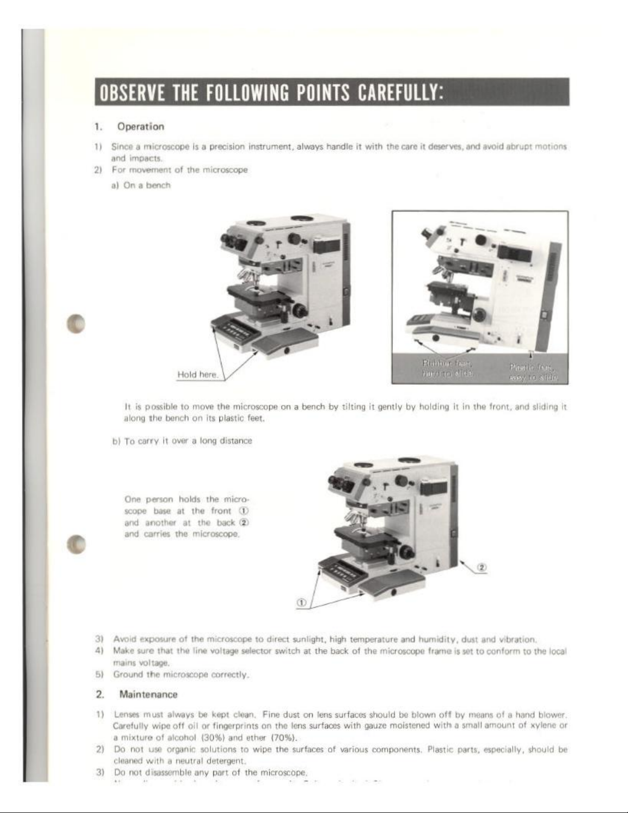
1.
Operation
1)
Since a microscope
and
impacts.
2)
For
movement
a)
On a bench
THE
of
Hold
LOWING
is a precision
the
microscope
instrument,
POINTS
always
handle
CARE
it
with
the
care
it
deserves,
and
avoid
abrupt
motions
here.
|
It is
possible
along
the
bi
To
carey
One
person
scope
base
‘and
another
and
carries
3)
Avoid
exposure
4)
Make
sure
mains
voltage.
5)
Ground
2.
the
Maintenance
to
move
the
bench
on
its
plastic
It
over a long
holds
at
at
the
of
that
the
microscope
distance
the
micro-
the
front
the
back
microscope
the
microscope
line
voltage
correctly.
microscope
feet
©
2
selector
on a bench
to
direct
switch
sunlight,
at
by
high
the
back
tilting
it
gently
by
temperature
of
the
and
microscope
holding
humidity,
it
frame
is
in
the
dust
and
set
to
conform
front,
and
sliding
vibration.
to
the
local
it
1)
Lenses
must
always
Carefully
a
2)
Do
cleaned
3)
Do
wipe
mixture
of
alcohol
not
use
organic
with a neutral
not
disassemble
be
kept
off
oil or
fingerprints
(30%)
solutions
detergent,
any
part
clean.
Fine dust
on
and
ether
to
wipe
of
the
microscope,
on
the
lens
surfaces
(70%).
the
surfaces
lens
surfaces
with
of
various
should
be
blown
off
gauze
moistened
components.
with a small
Plastic
by
means
of à hand
amount
parts,
especially,
blower.
of
xylene
should
or
be
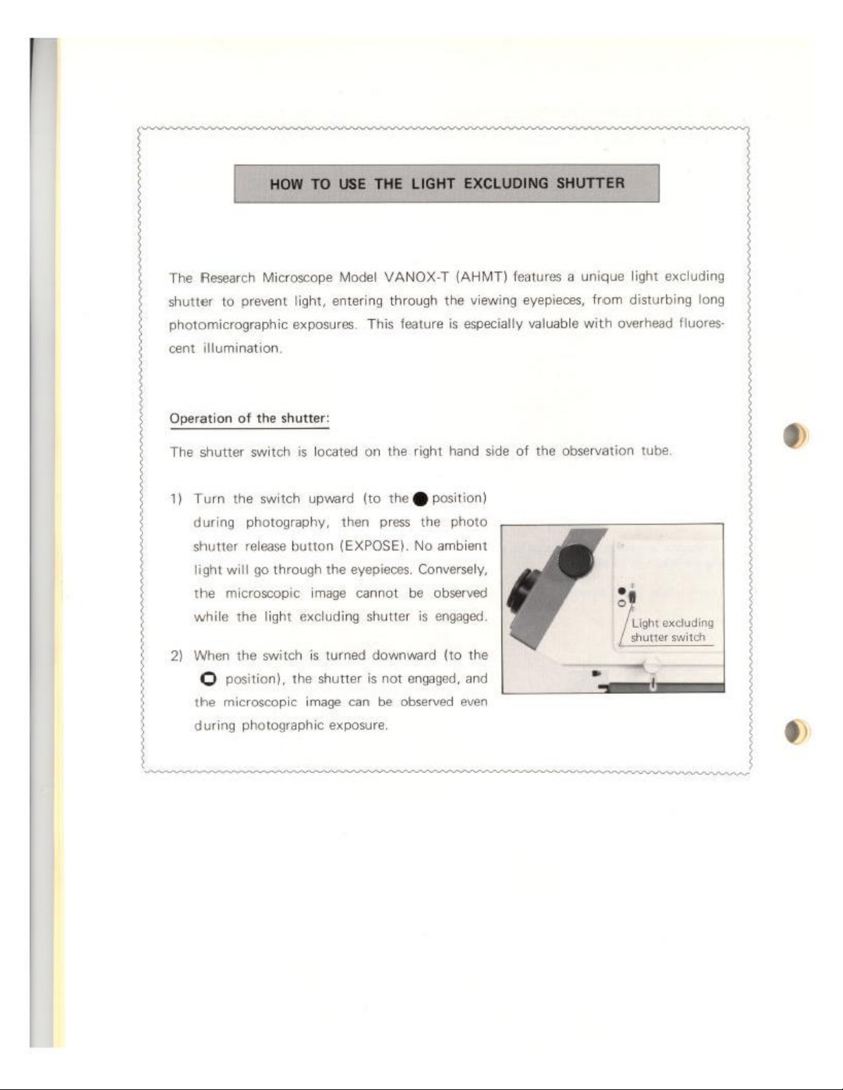
The
Research
Microscope
Model
VANOX-T
(AHMT)
features a unique
light
excluding
shutter
photomicrographic
cent
Operation
The
1)
2)
to
prevent
illumination,
of
shutter
Turn
during
shutter
light
the
while
When
©
the
switch
the
photography,
release
will
microscopic
the
the
position),
microscopic
light,
exposures.
the
shutter:
is
located
switch
upward
button
go
through
image
light
excluding
switch
is
the
image
entering
then
(EXPOSE).
the
turned
shutter
through
feature
This
on
the right
(to
the @ position}
press
eyepieces.
cannot
shutter
downward
is
not
can
be
observed
the
the
No
ambient
Conversely,
be
observed
is
engaged
(to
engaged,
viewing
especially
is
hand
photo
the
and
eyepieces,
valuable
side
of
the
even
from
disturbing
overhead
with
observation
tube,
|
|
=
Light
excluding
[shutter
switch
long
fluores
$
during
photographic
exposure.
3-2
Photomicrography
©
Identification
on
the
Indication
and
Function
and
of
the
Control
Panels
Various
Controls
13
13
e
D.
Special
©
Adapter
for
Applications
Large
Format
Camera
Backs
...............
24
LÉ
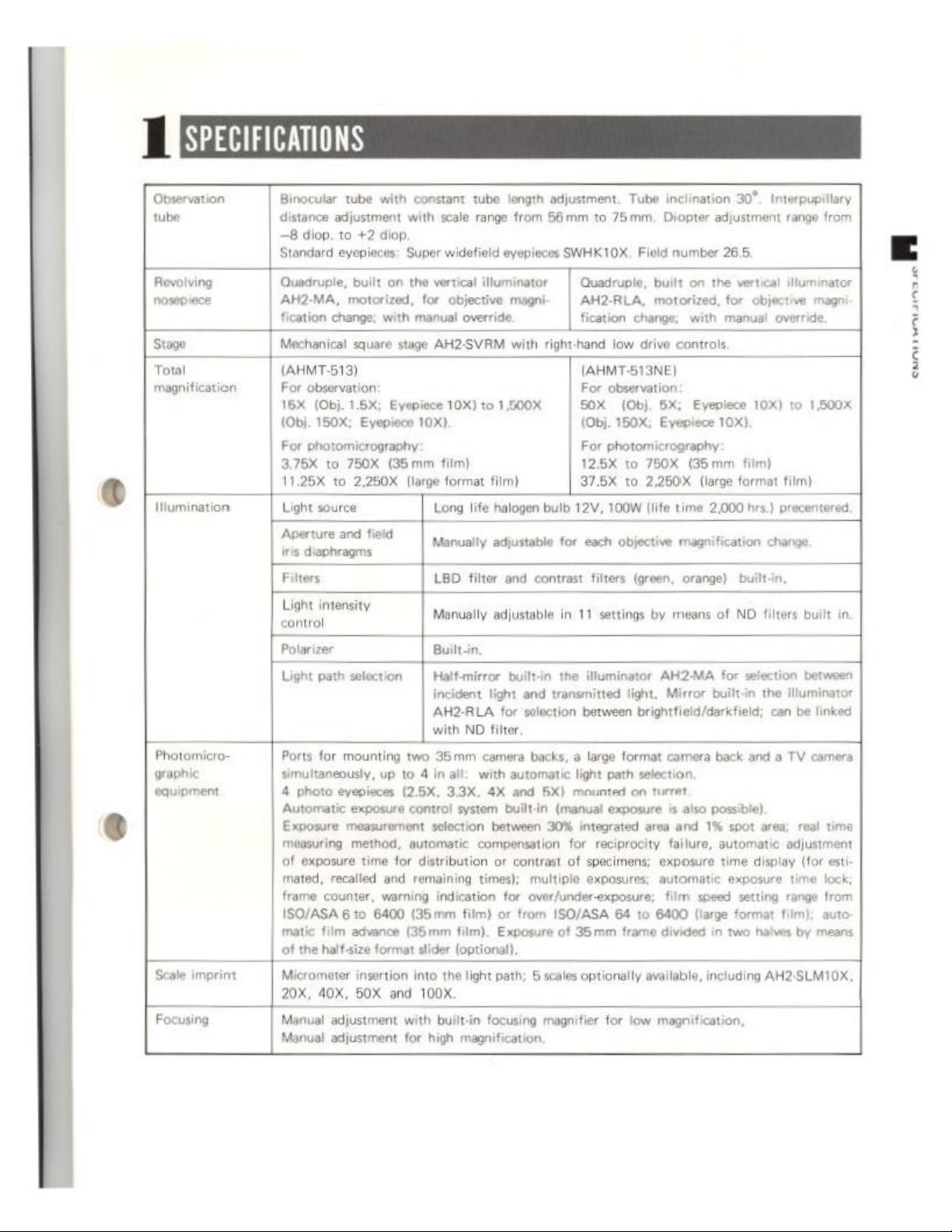
‘Observation
tube
Revolving
nosepiece
Stage
Total
magnification
Mumination | Light
Photomicro-
graphic
equipment 4 photo
Scale
imprint | Micrometer
Focusing
Binocular
distance
=8
Standard
Quadruple,
AH2-MA,
fication
Mechanical
(AHMF513)
|
For
16X
(Obj.
For
375X
11.25
‘Aperture
iris
Filters
ight
Polarizer
Light
|
Ports
simultaneously,
Automatic
Exposure
‘measuring.
of
tated,
frame
ISO/ASA
matic
of
20X,
Manual
Manual
tube with
adjustment
diop.
10
eyepieces:
change:
observation
(Obj.
150X;
photomicrograph:
to
75OX
to
source
and
diaphragms
ints
path
for
mounting
evepieces
measurement
exposure
recalled
counter,
610
film
the
half-size
40X, 50X
adjustment
adjustment
constant
with
+2
diop.
Super
built
on the vertical
motorized,
square
1.5%;
Eyepiece
2,250X
field
ο
selection
for
with
manual
stage
Eyepiece
10x).
(35
mm
(large
|
two
vp
to 4 in
(2.5X,
exposure
method,
time
advance
insertion
control
automatic
for
distribution
and
remaining
warning
6400
(35mm
(35mm
format
slider
into
and 100%.
with
for
tube
scale
range
widefield
objective
override
AH2-SVRM
10X)
film)
format
Long
life
Manually
v
LBD
filter
Moruolly
Buin
Haltsnirror
incident
AH2-RLA
with
ΝΟ
35mm
all:
with
33X,
system
selection
compensation
times);
indication
film)
film).
(optional).
the
light
builtin
high
magnification.
length
adjustment.
from
66
mm
to
75mm,
eyepieces
illuminator
mağni- | AH2-RLA,
with
10
1,500X | SOX
film)
halogen
adjustable
and
adjustable
builtin
light
for
filter,
camera
automatic
4X
and
builtin
between
ar
contrast
for
or
Exposure
path;
focusing
SWHKIOX.
|
Quadruple,
fication
right-hand
bulb
for
contrast
in
the
and
transmitted
selection
backs,
5X)
(manual
30%
multiple
over/under-exposure;
from
ISO/ASA
of
6
scales
magnifier
low
(AHMT513NE
For
observation
(Obj.
(Obj.
150X;
For
photomicrography
125X
to
37.5X
12V,
a
light
mounted
for
of
35mm
to
100W
each objective
filters
11
settings
iuminator
light,
between
large
format
path
exposure
integrated
reciprocity
specimens;
exposures;
64
frame
optionally
for
Tube
inclination
Diopter
Field
number
built
on
motorized,
change:
drive
controls
5X;
Eyepiece
750X
(35
2,260X
lie
time
magnification
e
(green,
on
low
orange)
by
means
AHZMA
Mirror
brightfield/derkfield;
camera
selection
turret
is
also
area
and
failure,
exposure
automatic
film
to
6400
divided
available,
magnification,
30”,
Interpupilary
adjustment
265.
the
vertical
for
with’
manual
Eyepiece
10).
mm
(large
format
2.000
builtin,
of
NO
for
built-in the
back
possible)
1%
spot
automatic
time
exposure
speed
setting
(large
format
in
two
including
range
iluminator
objective
override
10X)
to
film)
film)
hrs.
precentered
chan
ыы
filters
select
illuminator
can
be
and a TV camera
area;
real
adjustment
display
time
range
film);
halves
by
AH2-SLMIOX
from
magni
1.500x
builtin
linked
time
(fr
est
lock;
from
auto-
means
J
IDENTIFICATION
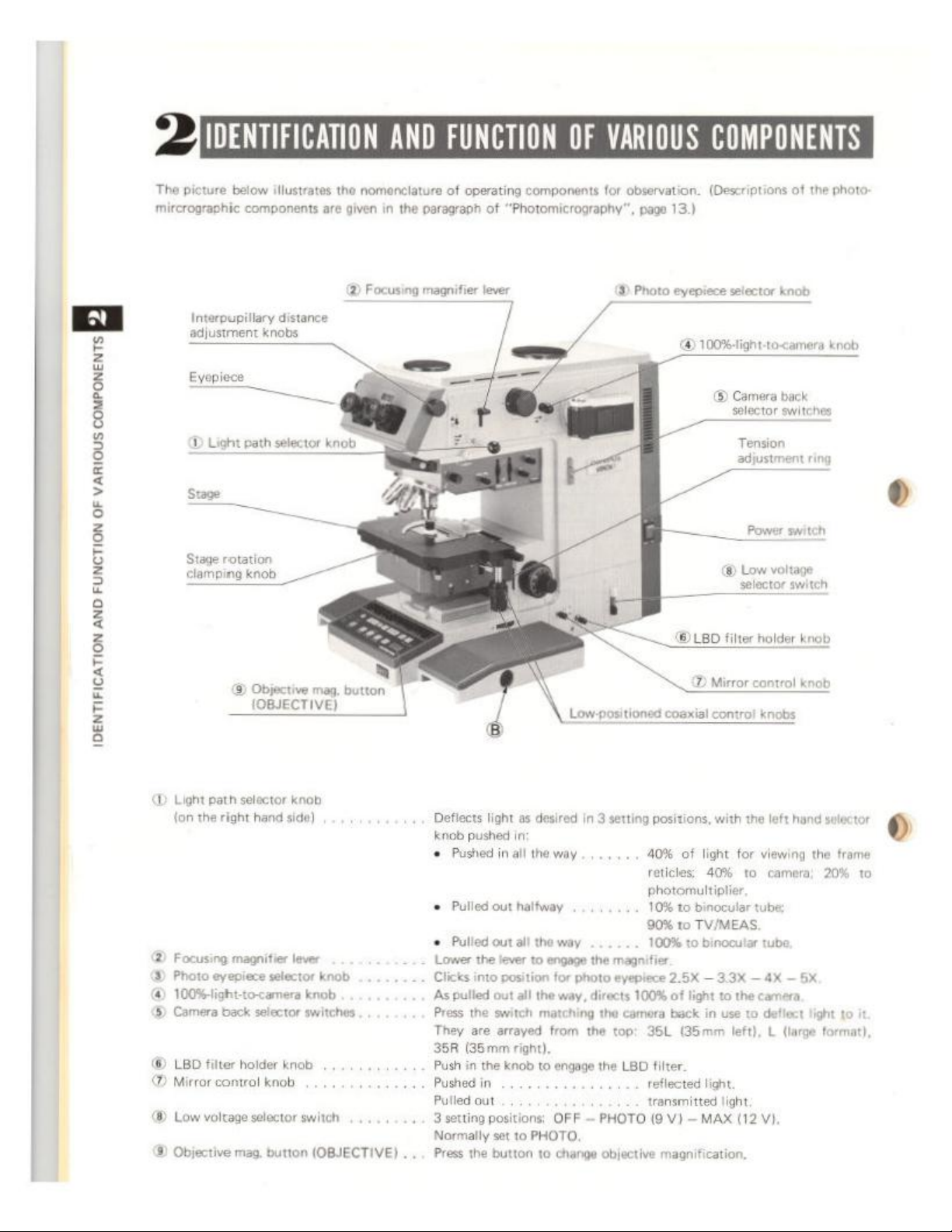
The
picture
mircrographic
below
illustrates
components
Interpupillary
adjustment
Eyepiece
=
distance
knobs
are
AND
the
nomenclature
given
in
the
paragraph
2)
Focusing
magnifier
FUNCTION
of
operating
of
"Photomicrography“,
lever
OF
components
VARIOUS
for
observation.
page
8)
Photo eyepiece
COMPONENTS
(Descriptions
13.)
D
100%-light-to-camera
©
Es
of
the
photo:
selector
selector
knob
knob
Camera
back
switches
Tension
adjustment
ring
Stage
rotation
mpingknob
Objective
_
(OBJECTIVE)
D
Light
path
selector
{on the
right
hand
®
Focusing
3)
Photo
@
100%ight-to-camera
(©)
Camera
LED
(©
Mirror
®
Low
®
Objective
magnifier
eyepiece
back
selector
filter
holder
control
voltage
knob
selector
mag.
一 @
mag.
knob
side)
lever
selector
button
knob
knob
switches
knob
switch
(OBJECTIVE)
button
'
+ 3 setting
.
...
d
Defiects
knob
+
©
Pulled
è
Lower
Clicks
‘As
Press
They
35R
Push
Püshedin
Pulled
Normally
Press
light
as
in
pushed
all
in
Pushed
out
halfway
Pulled
out
all
the
lever
into
position
pulled
out all
the
switch
are
arrayed
(35mm
in
right).
the
knob
out
positions:
set
to
the
button
Low
-positioned
desired
the
the
to
.........
PHOTO,
in
3
setting
way
way
engage
the
magnifier
for
photo
eyepiece
the
way,
directs
matching
from
to
to
the
camera
the
top:
engage
the
LBD
OFF — PHOTO
change
objective
—
©
LED
SD
coaxial
positions,
40%
of
reticles:
photomultiplier
10%
to
binocular
90%
to
TV/MEAS.
100%
to
2.6% — 3.3X — 4X — 5
100%
of
light
back
35L
(35mm
filter.
reflected
transmitted
(9
light,
V) — MAX
magnification,
Power
selector
filter
Mirror
contro!
with
for
light
40%
binocular
to
the
in
use
left), L (large
light
(12
switch
voltage
Low
switch
holder
contro!
knobs
the
left
hand
viewing
to
camera;
tube;
tube
camera,
to
deflect
VI.
knob
knob
selector
the
frame
20%
to
light
to
it
format),
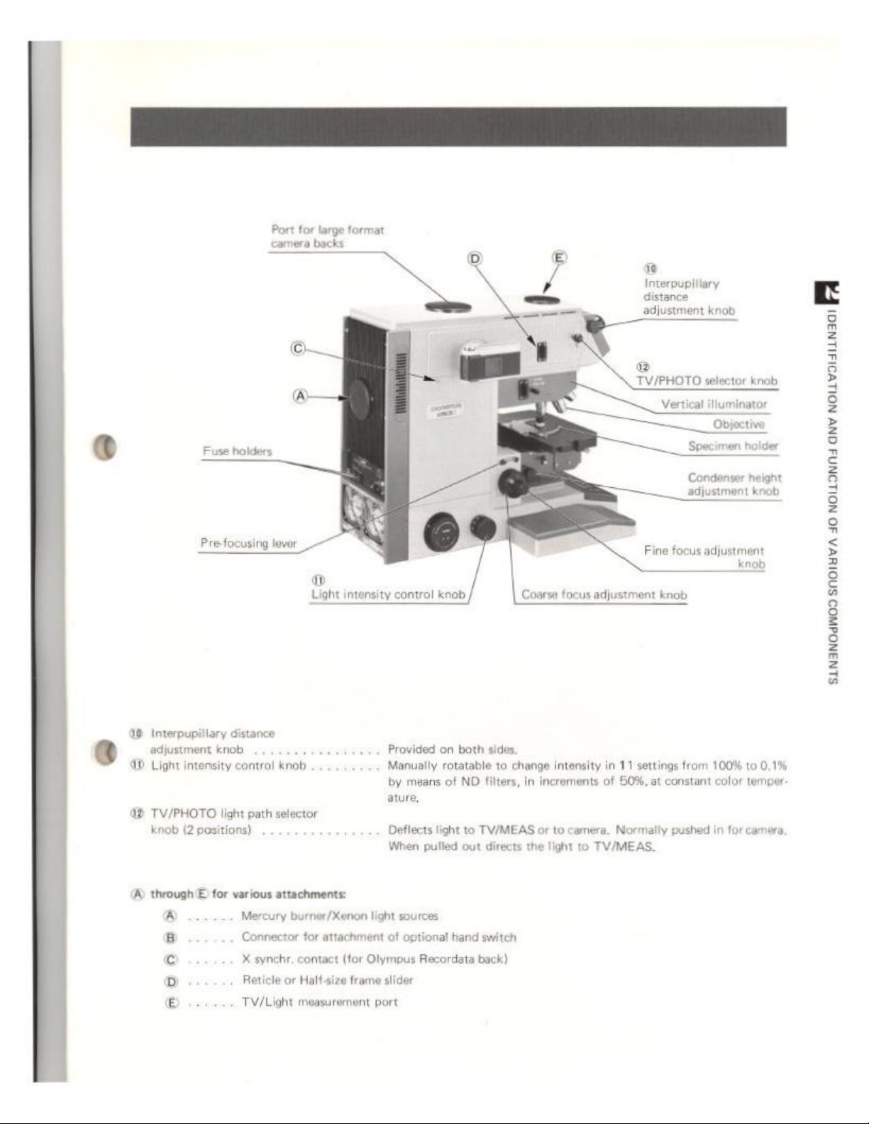
Port
for
large
backs
camera
format
Interpupiliary
distance
adjustment
®
TV/PHOTO
knob
selector
Specimen
knob
‘Objective
holder
加
wouvouunaa
ovy
o
Pre-focusing
49
Interpupillary
adjustment
@®
Light
intonsity
42
TV/PHOTO
knob
(2
distance
knob
contro!
light
path
positions)
lever
—
n
Light
intensity
ye
knob
selector
control
Provided
Manually
by
ature,
Deflects
When
knob
on
both
rotatable
means
of
ND
light
to
pulled
out
Coarse
sides,
to
change
intensity
filters,
in
increments
TV/MEAS
directs
or
to
the
light
focus
adjustment
in
11
of
60%,
camera.
Normally
to
TV/MEAS.
Condenser
adjustment
Fine
focus
adjustment
knob
settings
from 100%
at
constant
pushed
color
in
height
knob
knob
to
0,1%
temper
for
camera,
wouownd
sawanodnoosnoluvAdo
(A)
through E for
various
attachments:
Mercury
Connector
X
Reticle
TV/Light
burner/Xenon
for
synchr.
contact
or
Half
measurement
light
sources
attachment
(for
size
of
optional
Olympus
frame
slider
port
Recordata
hand
switch
back)

Vertical
BY
wscoen
OF
illuminator
(for
brighttield)
Analyzer
insertion
slot
AH2.MA
®
Contrast
Aperture
Siaphrago
filter
iris
knobs
FUNCTION
AND
am
IDENTIFICATION
D
Halt-mirror
©
Contrast
©
Polarizer
©
Auxiliary
®
Analyzer
®
Additional
knob
filter
knobs
knob
lens
knob
insertion
ilter
®
Halt.mirror
||
Pulled
G
o
Pulled
Normally
slot
insertion
slot
ference
Insert the
Optional
knob / @
Polarizer knob |
@
4
out
to
engage
out
to
engage
pushed
observation
analyzer
filters
can
Auxiliary
for
for
green
orange
in.
with
provided,
be
ens
knob
reflected
transmitted
the
the
Pulled
inserted,
lah
lig
contrast
polarizer
objectives
filters:
filter.
out
for
Field
polarized
50X
or
higher.
light
iris
diaphragm
or
differential
inter
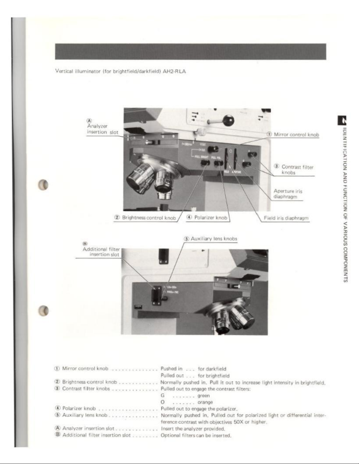
Vertical
illuminator
(for
brightfield/darktield)
AH2-RLA
å
insertion
Additional
slot
|
®
Brightness
filter
control
«©
knob
// @ Polarizer
©
Auxiliary
knob
lons
knobs
©
Mirror
©
Contrast
Field
iris
diaphragm
control
knob
filter
BM
ouvuun
ov
wouonni
sunanwodnoosnoluvAdo
D
Mirror
control knob
®
Brightness
@
Contrast
@
Polarizer
©)
Auxiliary
®
Analyzer
B
Additional f insertion
control
knob
fitter
knobs
knob
lens
knob
insertion
slot
..
slot
Pushed
in...
Pulled
out . ..
Normally
G
o
Optional
pushed
Pulled
out
to
engage
Pulled
out
to
engage
Normally
ference
Insert
pushed
contrast
the
analyzer
filter
for
darkfield
for
brightfield
in,
Pull
it
out
to
the
contrast
green
orange
the
polarizer
in,
Pulled
with
objectives
provided.
inserted,
filters
out
50X
increase
for
polarized
or
light
higher
intensity
light
in
brightficld
or
differential
inter
3
JOPERATING
THE
MICROSCOPE
à
8
È
2
8
é
È
2
|
=
=
κα
WAN
Operation
in
Microscope
the
Putting
of
Summary
PRE
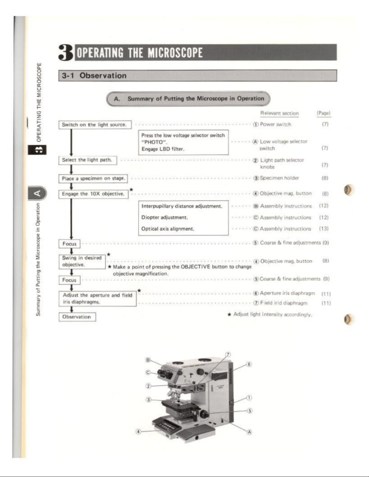
Gaec).
Select
the
light
Ega
Swing
に
ーーー
[Four]
Adjust
iris
Observation
a
OX
in
desired
aperture
the
diaphragms.
ο
σος
path.
bles,
|*
#
Make a point
objective
field
and
Press
the
low
voltage
“PHOTO”.
Enga
LBD
Interpupillary
Deeer
pti
of
pressing
magnification.
*
fer
distance
fuen
axe
lomem
the
το
selector
OBJECTIVE
switch
adjustment.
button
to
change
x
Adjust
το
Releant
@
Power
voltage
Low
(A)
sich
®
Light
path
knobs
(A)
Specimen
©
Object
(8)
Assembly
©
Awonbty
Слить
©
Coarse & tine
@
Objective
&
Course
@
Aperture
©
@
Field
irid
intensity
light
section
switch
selector
(ον)
σ
m
selector
m
holder
mag
button
instructions — (12)
auction
instructions
adjustments
mag.
button
adjustments
fine
diaphragm
iris
diaphragm
accordingly.
18)
18)
(12
(3
(9)
(8)
(9)
(17)
(11)
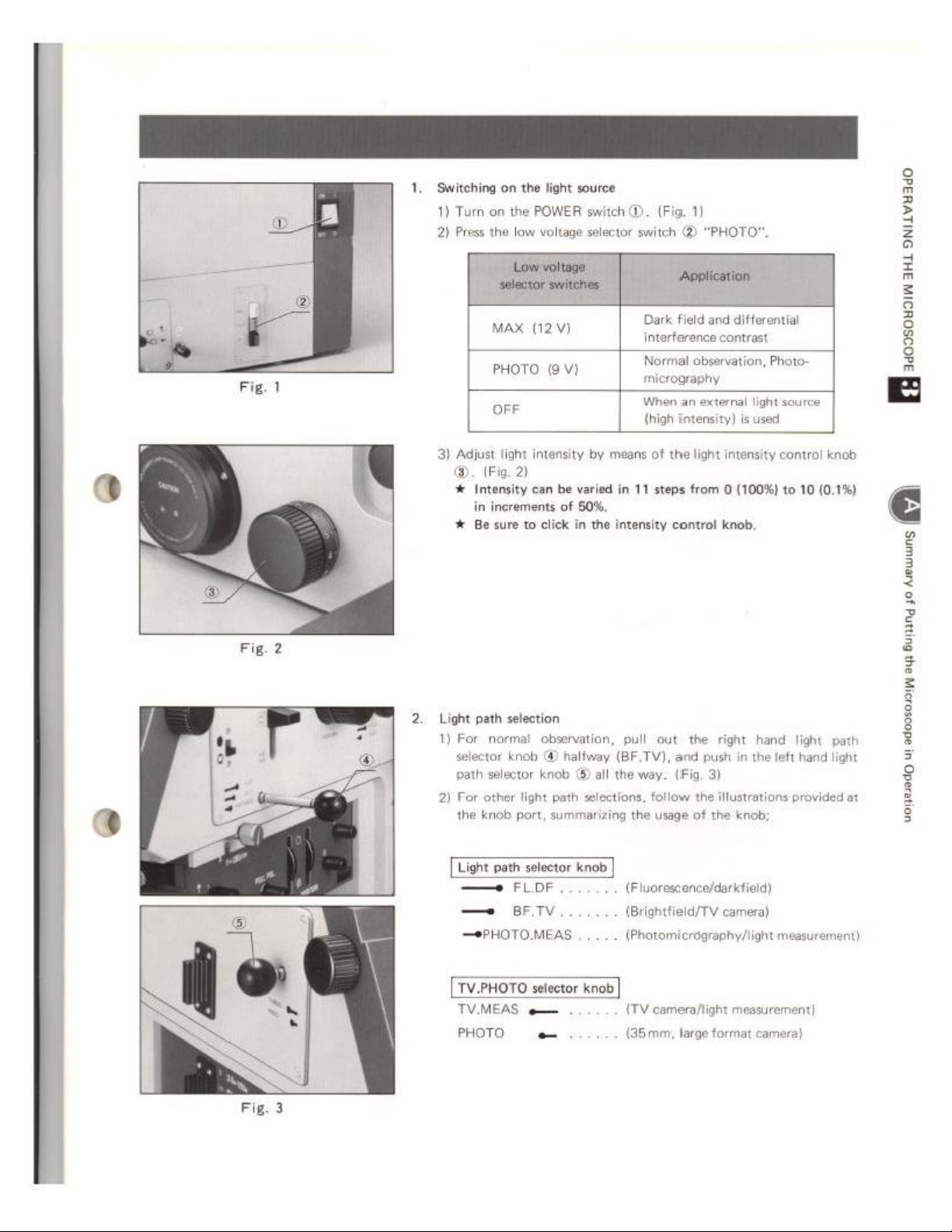
‘Switching
1)
2)
on
Turn
on the
Press
the
the
POWER
low
voltage
light
source
switch
selector
D.
(Fig.
switch
(2)
1)
“PHOTO”.
©.
4
Intensity
in
# Be sure
Light
path
1)
For
selector
path
2)
For
the
=
~
(Fig. 2)
can
be
varied
increments
selection
normal
knob @ halfway
selector
other
knob
of
50%.
to
click
in
the
observation,
knob © all
light
path
selections,
port,
summarizing
in
intensity
pull
(BF.TV),
the
the
ey
11
steps
control
out
and
way.
(Fig.
follow
usage
from
the
-eg
(100%)
to
10
knob.
right
hand
light
push
in
the
left
hand
3)
the
illustrations
of
the
knob:
provided
(0.1%)
path
light
at
Light
path
selector
—
—
TV.PHOTO
TV.MEAS e 一
PHOTO
FLoF
eri
一
PHOTOMEAS
knob
selector
knob
e
(Fluoresconce/darkfield)
(Brightfield/TV
(Photomicrography/light
{TV
camera/light
(35mm;
camera)
measurer
large
format
measurement)
camera)
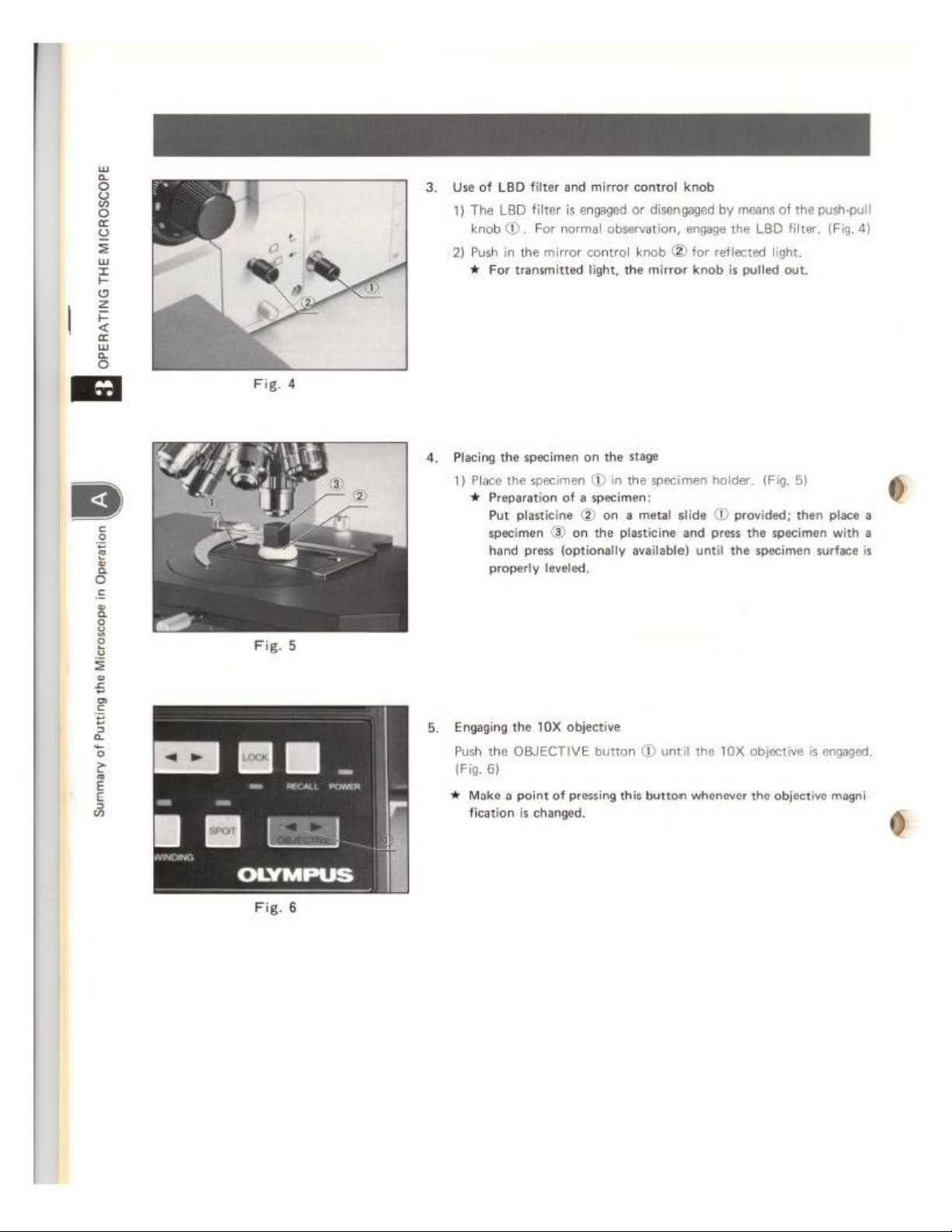
3.
Use
of
1)
The
knob
2)
Push
#
4.
Placing
1)
Place
YR
LBD
filter
and
mirror
LBD
filter
is
engaged
@,
For
normal
observation,
in
the
mirror
control
For
transmitted
the
specimen
light,
on
the
thespian
ca
ein
Put
plne
toecimen
Fond
press
propery
Gn
on
te
(optionally
lve,
control
or
knob
the
knob
disengaged
«3)
mirror
by
engage
the
for
reflected
knob
is
stage
inthe
paia
a
metal
platine
aval
o.
lido
O
provided; thn
and
pres te
uni
the
means
of
the
push-pull
LBD
filter.
(Fig.
light.
pulled
out.
(Pi.
8)
place
specimen
spsimen
in
surface
4)
0
a
5.
Engaging
Push
the
(Fig.
6)
+
Make a point
fication
the
10X
objective
OBJECTIVE
is
changed.
button
of
pressing
(D
until
this
button
the
10X
objective
whenever
the
objective
is
engaged,
magni
6
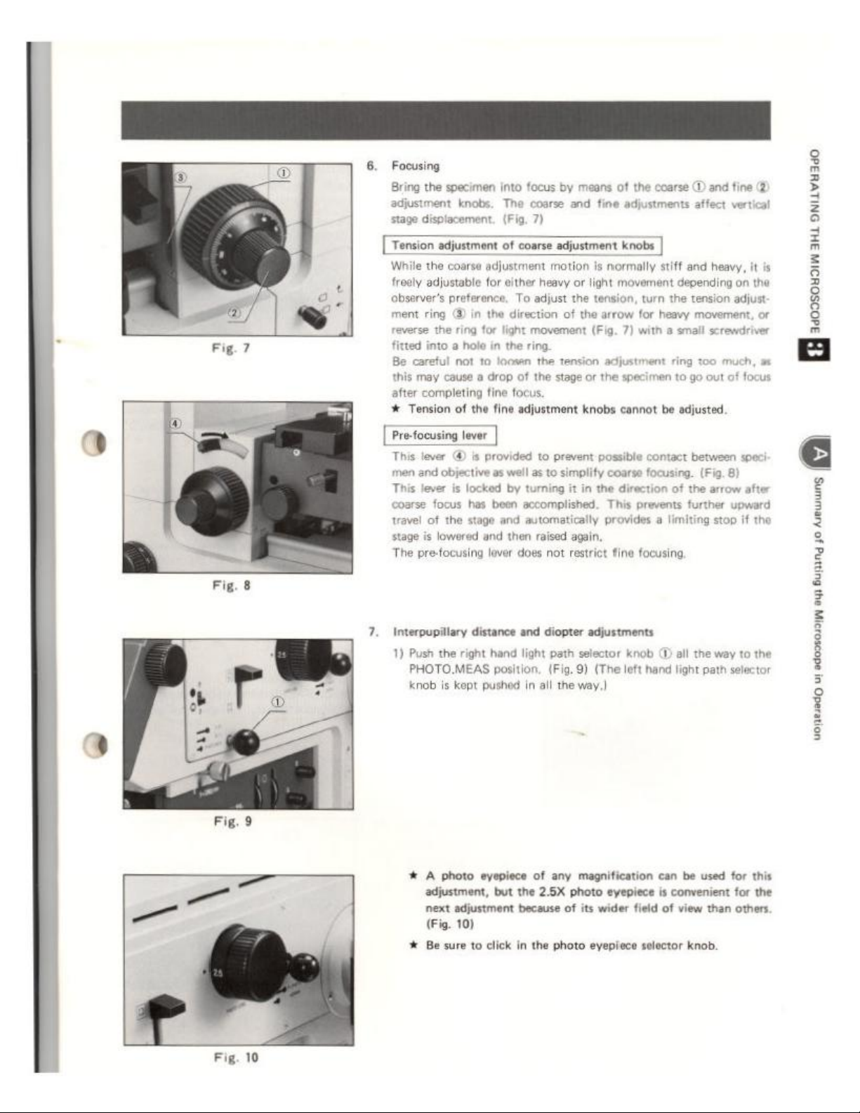
Fig.
7
6.
Focusing
specimen
the
Bring
adjustment
stage
[[Tersion
While
freely
observer's
ment
fitted
Be
careful
this
after
#
Tension
knobs.
displacement.
adjutant
the
coarse
adjustment
adjustable
for
preference,
ring @ in
the
ring
for
into a hole
not
to
may
couse
a
of
the
drop
fine
completing
by
focus
into
The
(Fig.
of
οσον
and
coarse
7)
adjustment
motion
either
heavy
or
To
adjust
the
the
direction
light
in
the
loosen the
of
of
movement
ring
tension
the
stage
focus
fine
adjustment
coarse
the
of
means
adjustm
fine
is
normally
light
movement
tension,
the
arrow
(Fig.
knobe
]
stiff
turn
for
heavy
7)
with a small
adjustment
or
knobs
the
specimen
cannot
be
(2
fine
©)
and
and
heavy,
it
is
depending
the
tension
ring
to
go
on
the
adjust
movement,
screwdriver
too
out
or
much,
of
focus
adjusted
개
This
men
and
This
coarse
travel
stage
The
pre-focusing
7.
Interpupillary
1)
Push
PHOTO.MEAS
knob
|
lever @ is
lever
of
is
provided
objective
focus
lowered
the
is
as
is
locked
has
the
stage
and
lover
distance
right
hand
kept
pushod
|
to
prevent
well
as
to
simplify
by
turning
it
in
the
been
accomplished.
and
automatically
then
raised
again.
does
not
restrict
and diopter
light
position,
in
all
adjustments
path
selector
(Fig.
9)
(The
the
way.)
possible
coarse
This
provides
contact
focusing.
direction
fine
knob
left
of
prevents
a
limiting
focusing
(D
all
hand
light
between
the
the
speci
(Fig.
8
arrow
after
further
way
path
upward
stop
if
the
to
the
selector
3
3
=
$
ê
3
3
>
„=
=
Fig.
10
* A photo
adjustment,
next
(Fig.
+
Be
eyepiece
but
adjustment
10)
sure
to
click
of
any
magnification
the
2.5X
photo
because
in
the
photo
of
its
can
eyepiece
wider
eyepiece
is
convenient
field
of
solector knob.
be
used
view
than
for
this
for
the
others.
 Loading...