

Page 1
Scanned on 11 March 2010 by Paul Henry Golding (paul@paulgolding.id.au)
from original supplied by Windsor Davies.
This copy may be distributed freely, but must not be sold.
OLYMPUS
UNIVERSAL
MICROSCOPE
MODEL
VANOX
REPAIR
MANUAL
OLYMPUS
Page 2
TO OLYMPUS MICROSCOPE SERVICING PERSONNEL
Model
This repair manual describes repairing procedures in principle
microscope.
The
must
Therefore,
long
The
may
The
variationofinterpupillary
in this manual
tools
In
microscopist
For cleaning lenses, a
should
Requisites
1.
2. Never fail
3.
4.
5. Make repairs
VANOX
focusing mechanismofthe microscopeislargely
assure
time,
however,itwill
special
notbedisassembledorparts maybedamaged.
observation
for
adjustment are
the
diescriptions contained in this manual,
be
madeto"HowtoClean
for
Firstofall, ascertain
a)
Find
Prior
b)
efficient
After
completing
microscope
Be
careful
specified
(AH)
robbustness,
the
focusing mechanism
tools
tubeisequipped
after
sitting
repairs:
to
check
out
what
to
repair,
way.
to
not
for
purpose.
promptly
is
listed in this manual must
disassemblyofthe prism. Do
not
in the observing position through the microscope, unless other wise specified.
liquid
what
the
parts
think
the
make sure no defect should be
to
deform
designed
durability
require lubrication and repairtoprotectitfrom
distance between binocular tubes) and mustbeadjusted elaboratelyasdescribed
availableatthe
entire
are
repair, check the functionsofnot
and
as
a versatile research microscope equipped
and accuracy compatible
can
rarely
be
with
a constant tube length adjustment
site.
"right"
mixture
partsofthe microscope the userorownerofwhich wishes youtorepair.
defective and
of
repair parts during the assembly; makeitpracticetouse
accu
of
alcohol (3) and ether (7) should
the
Microscope" whichisavailable upon separate request.
functionofthe microscope before you commence its repair.
how
the best possible order
rately.
different
be
troubled in practical
employed
not
attempt
and
"left"
much they are damaged.
of
left
unremedied.
with
various accessories.
for
its standard configurationasa biological
from
thatofBHorBH2 since the
with
heavy accessoriestobe
use.
Afterithas
dust,
humidity,
for
disassembling the instrument; otherwise
(to
automatically compensate
disassemblyofthe prism when the special
are
defined in the directionasseenbythe
be
used.
For
disassembling the defective parts in a most
only
the re-assembled parts
attachedtoit.
been
etc.
details, reference
but
also the entire
tools and jigs
former
used
for
a
it
for
Page 3

CONTENTS
1.
REPAI R TOOLS
2.
EXPLODED PARTS
3. DISASSEMBLING AND REASSEMBLING PROCEDURES
FOR A-F (AH-FRAME) 16
AND
GREASES 1
DIAGRAMS
2
4. DISASSEMBLING PROCEDURES,
OPTICAL
5. DISASSEMBLING
FOR A-SV (STAGE) 54
6. DISASSEMBLING
FOR A-CH (CONDENSER HOLDER) 70
7. DISASSEMBLING, REASSEMBLING AND ADJUSTING
PROCEDURES FOR
ALIGNMENT
AND
AND
A-AL
OF A-Bi (BINOCULAR TUBE)
REASSEMBLING PROCEDURES
REASSEMBLING PROCEDURES
(AUXI
AND
L1ARY LENS) 78
FOCUSING
AND
35
Page 4
1.
REPAI R TOOLS
1-1
Regular Tools
AND
GREASES
1-2
OT0011
OT0015
OT0016
OT0018
OT0021
OT0023
OT0035
OT0061
OT0079
OT0216
OT1028
OT1131
OT1141
OT1143
OT1144
Greases
OT2008
OT2010
OT2022
OT2024
Set
of
screwdrivers(6pes.)
Phillips screwdriver (medium
Phillips screwdriver (large size)
Screwdriver (large
size)
Adjustable spanner (rounded)
Handleofsmall
size
Phillips screwdriver, using OT1141
Tweezers (special made)
Sharp
point
pliers (size 170 mm)
Pliers (size 170 mm)
SetofAlien
Araldite
Shellac (20
Phillips screwdriver
Tension
Tension
Grease
Grease
Grease
Grease
wrenches (8 pes.)
(adhesive)
g)
(adhesive)
gauge
(200
gauge
(500
(20
g)
(20
g)
(20
g)
(20
g)
tip,
g)
g)
using
size)
OT0023
1-3
Special Tools
C-1
C-15
KKAA0044
KKAA
KKAA1466
KKAA5853
KC-2002
KC-2003
KC-2005
KC-2023
KNOO05
KN0029
SKNOO01
A-KCOO05
A-KCOO08
A-KC0010
A-KC0023
1-4
Others
FK2.5X
35WF10X
1456
10X
eyepiece
with
cross hairs
Focusing magnifier (PM-FT-36)
Pin face wrench
Pin face wrench (2
Pin face wrench (2
pes.
pes.
are
are
needed)
needed)
Pin face wrench
for
Taper reamer
Holder
Cutter
Jig
for
for
for
washerofVanox
holding
Vanox
taper reamer
pinionofVanox
Centering objective
Special eyepiece
Gauge
for
Centering plate
Jig
for
photo
Standard tube
Jig
for
prism alignment
for
checking
for
stage
checking
tube alignment
for
Vanox
checking
tilt
for
A-Si
A-AL
Photo eyepiece
Finder eyepiece
exit
pupil
-1-
Page 5
2. EXPLODED PARTS
CMK
AA
589~\.
~
'''''L..
f1'
4X25SAJ
AA 589100
.
b:?'
C\
C\
AA
AB
6x36SA
AA 589300
NP
DIAGRAMS
3x8SA,
'
'./
/'
/,/
~B
~AA
,/
~AA
/
./~~:::=~~
~
,
~"'~
'-.
.
..____AA
~Y1
AA
591000 I
364000
~
195600
~~~~~O
211800
AA 601700
NN
3SA
AA
580~'
I !
~
_,
,
-./),
/'
<-
"-"
./-
~
......
'~
111
~~
./
i l
-AA
lAA
AB
589400
583400
575400
3Xl0SA
'l
AA
CM[1:'h~E=:=~/
AA
5014OO~
AA 501500
AA
501600 .
CMK2.6X8SA~
CMK
3XI4SA//~,(l
AA~J/
AA
589500../
I':rS3(hOO
AA~~~
AA
LP
AA
AA
AA
Q
IR?'????-------
LP
AA
ACU
2.6X3SA-
..
590600~
036400-
363900-
456100 I I
602200------
818888~
590400
,.-/
/~
/'
,/
CMK
~
-
_______
--/
/d/
2.6X4SA
AA
589600
~
J::/
§'
J
I
~~AA
AA 764000 -----AA590700
I
J-~>
Ms914/JO
@(t,IS
~
ild
AA
CTK
lSU)
UTlU
.
601300-
2X5SA-----.....
~AA~
~
AA
3~900
590900
!
--AA
583500
-2-
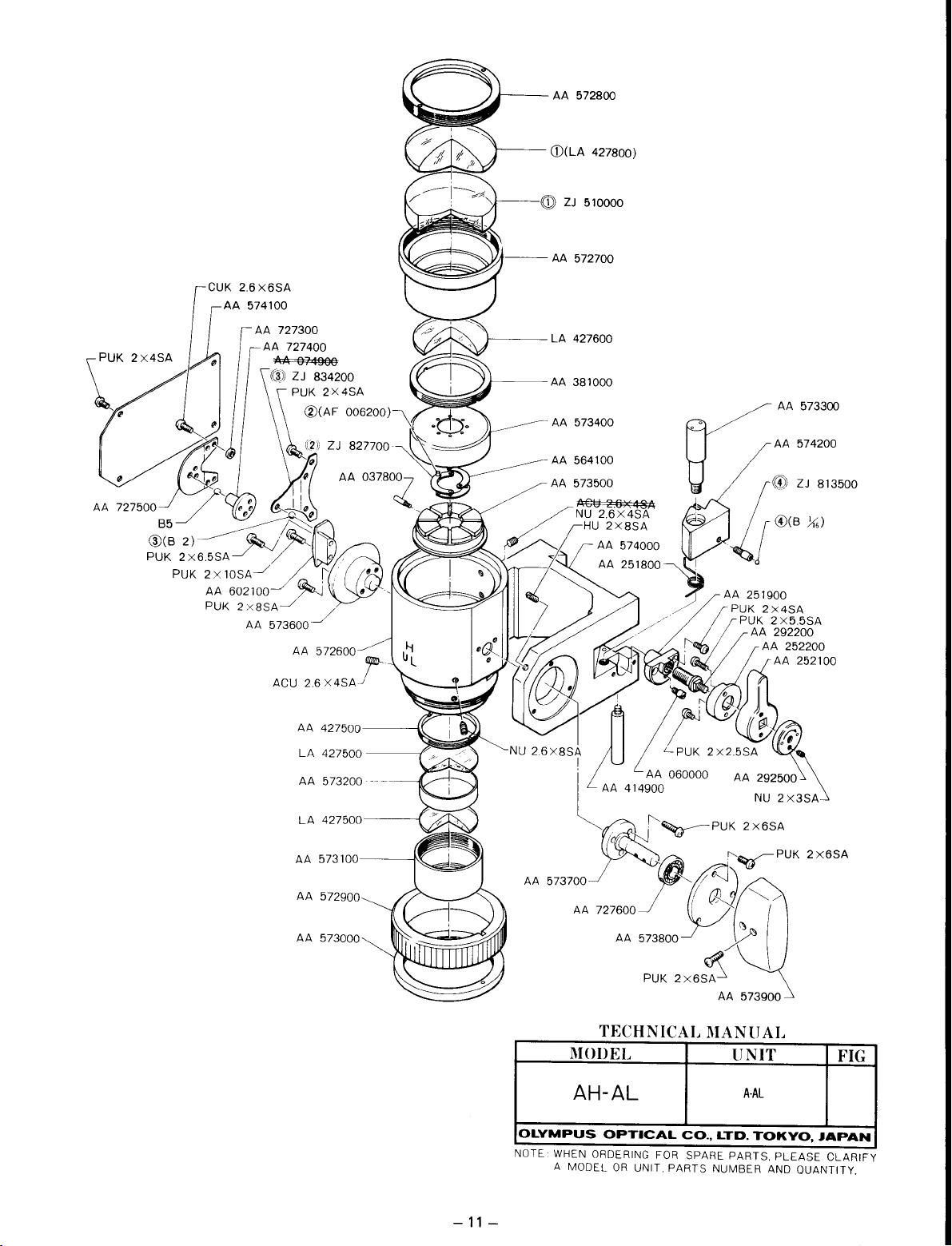
TECHNICAL
MODEL
AH-F
OLYMPUS
NOTE:
OPTICAL
WHEN
ORDERING
A MODELORUNIT. PARTS NUMBER
FOR
MANU
CO,.
SPARE PARTS. PLEASE CLARIF'r'
LTD,
UNIT
A-S
TOKYO.
AL
AND
FIG
JAPAN
OUANTlTY.
Page 6
~~
AA 583400
AA 322800
-3-
MODEL
AH-F
OLYMPUS
WHEN ORDERING
NOTE: A MODEL
TECHNICAL
PTICAL
0
OR
OR
~
PARTS NUMBER
UNI
.
CO.,
SPARE
MA~~I~L
A·S·2
TOKYO,
LTD.
PARTSA~~
JAPAN
EASE CLARIFY.
QUANTITY.
Page 7
AA
583400
AA
236700
AA
236800
(f
GA
030200./'\
/
.
I
AA 649600
DJ
CTK
3x5SA
\~"
!
.\·~I
'f
EV
0020
/
"4t~
A~~
A~6
~
40S0;OO~
0030
- I
/
6N
~
"
3SA
CMK
3 X
5SA
• AA
.....
;;)~CMK
'~DJ
• CSK
CTK 3
x5SA
OS
AA
6N
DJ
CTK 2
0033
649100
3SA
0063
649500
3x5SA
0050
3x6SA
x5SA
OS 0003
650100~
AA
OF
0001 (for 100V) .
OF
0002
OF
0003A~or3~~~0~__
~-oooooo
ES
001000(for
ttS=000600
ES
001100(for
AA-~
AA
761200/
/~~
------
100V)_~
200V)
CMK 3
x4SA
~
_~
AJ--
/
I .
·0
~
~~
I@
.
i
~~,
.t-
~
~.AA
/
/.
~~:s:x~~~-r-'"
I CMK
I~'
DW
PUK
I
//
~~
'::'
/VSW
~6N
3x5
0004
2x3SA
7091100
~
4SA
4SA
SA
-----
DW
CMK
3x5SA
:-=
Of
•
00i5400
l)fc.~
DT
0045
DT 0046 (for
MODEL
(for 100V)
TECHNICAL
0021
200V)
OLD
MANU
UNIT
TYPE
AL
FIG
AH-F
OLYMPUS
NOTE:
WHEN ORDERING FOR SPARE
A MODELORUNIT.
-4-
OPTICAL
A·B·2
CO.,
LTD.
TOKYO,
PARTS
PARTS.
NUMBER AND QUANTITY.
PLEASE
JAPAN
CLARIFY
Page 8
AA
583400~
AA
761100-~
NEW
TYPE
6N
3SA
ft------
AA
649900
U /l
•
~
_
(I"
•
"""
~
/
,
~CMK
f~=DW
~DW
----CMK3x5SA
4x6SA
0008
0021
OF
0001
DFeee2-
0003
DT
0045
DT
0046
(for
(for
100V)
200V)
._____'-
~
I \
~
I
tl,=",'~,'~~~K33:~~~A
I "
-,'
'~
'"
""
~
ES
0010
ES 0011 (tor
",,-
EL
0008 (for 100V)
EL
0009
"'-SW
3SA
~CMK
CMK
TECHNICAL
MODEL
AH-F
3X4SA
3x5SA
(tor
(for
100V)
200V)
200V)
MANUAL
UNIT
A-B-2
FIG
-5-
OLYMPUS
NOTE:
WHEN ORDERING FOR SPARE PARTS.
A MODELORUNIT.
OPTICAL
PARTS
CO.•LTD.
TOKYO.
NUMBER AND QUANTITY.
PLEASE
JAPAN
CLARIFY
Page 9
591900
-AA
iQj)ZJ 812600
245000-"
AA
245000
591800
AA
\,AA
591700\
AA
\
lOUO~,
3x
NP
579300\
AA
\
591100,
AA
\
5X20SA\
AB
)l>
,,,,,,,,,J"
594000
004500
AA
AA
903100-/
004300
: AA
IAA
",
AA
')
AA 592500
'-
2774~'
-'~
AA
593800
~AA
• I
DIAGRAM
rAU'OW
PARTS
EXPLODED
~
I UNIT
AH-F
MODEL
CLARIFY
QUANTITY,
yO,JAPAN
PLEASE
AND
SPARE PARTS,
FOR
G
UNIT, PARTS NUMBER
OR
A MODEL
AA 205800
I
I
O'l
Page 10
145600
AA
146600
AA
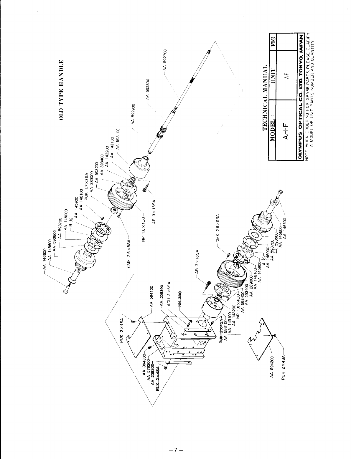
TYPE HANDLE
OLD
146000
AA
~
I AA 593600
/ I AA 593700
/ I
f
B){,
I
/ I \
x3SA
17
r PUK
! r AA 146100
I ! AA 145900
'./
"'"
".
I
~
592700
AA
592900
AA
593100
AA
143100
AA
/,'
/
'tI
/
/
,/
'/
! .
"/
"~;/
IlV
~I.
'
~
~
,,~
//
A
r A 289000
'/
593400
AA,
A 593200
r AA 143200
..
A,
_
r
' r _
..
/.
/',
~~
..! / / /
• ,
..'
-
"
~
I.
ft!r~~
T , .
2.6x5SA-/
CMK
"'/,/
'''7
~
'"
~
''-./~!~
/
x4UO---./
16
NP
594100
AA
• I
"
~
3X16SA~
AB
~~
3X16SA
f"'-.~AB
~
"',
J",I\I.'
/
143100-"
AA 143200
593100-
!AA
AA
593400
AA
1.6X4UO
AA 593400
NP
I
.\
I
145900~
AA
AA 146100
AA 289000
FIG
UNIT
TECHNICAL MANUAL
MODEL'
.
~
/
~g6~6600~/'
J
593500~
AA
AA
146000--1
){,-.J
AA 593700
B
AA
A-F
AH-F
CLARIFY
JAPAN
QUANTITY.
PLEASE
AND
TOKYO,
LTD.
SPARE PARTS.
CO.,
FOR
UNIT. PARTS NUMBER
OR
OPTICAL
ORDERING
A MODEL
WHEN
OLYMPUS
NOTE
"-
" I
//~U,
/
579200~
AA3643~0
------
AA
••
I
......
AA 594200
2X4SA
PUK
Page 11
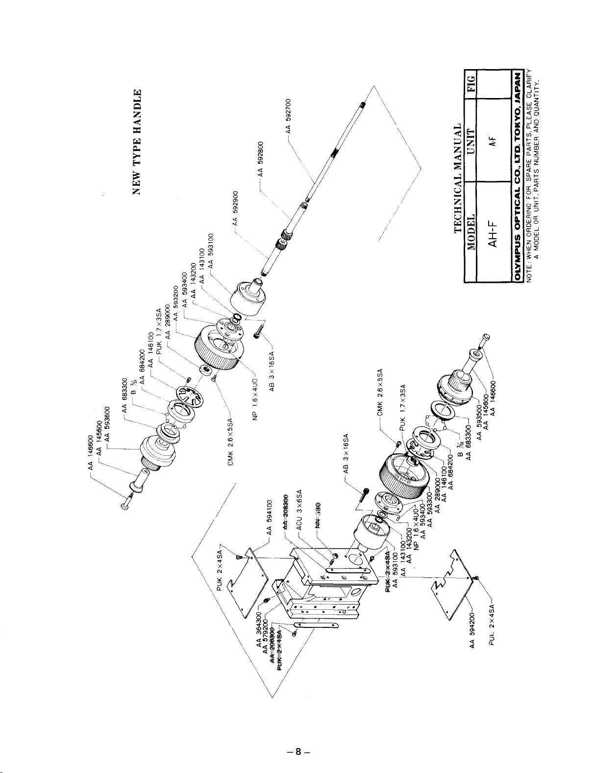
TYPE HANDLE
NEW
AA 592900
r-
AA 592800
/------
592700
FIG
A-F
UNIT
TECHNICAL MANUAL
AH-F
MODEL
CLARIFY
JAPAN
QUANTITY,
PLEASE
AND
TOKYO,
PARTS,
LTD.
NUMBER
CO.,
PARTS
UNIT,
OR
OPTICAL
A MODEL
WHEN ORDERING FOR SPARE
OLYMPUS
NOTE:
AA 145600
AA 146600
593600
,AA
(
NP
2.6X5SA~/
CMK
"~
/
2X4SA
//~
~
/PUK
AA 364300
///
5792(
~
!t)lj3OO-
//.
A'"
..
~I
( IS
:!J
f"U~:
~
3X16SA
I'~AB
2X4SA
PUk
I
I
(Xl
Page 12
AA 575600
3x25SA
CMK
AA 371900
AA 372400
046700
LP
580900
AA
rJ..:J
v'
~
046600
AA SA7
LP
"",-
224500
3X4SA~
583100,
AA
HU
AA
49800
749700
,
AA
AA
~
~
."
~
:
12SA • I
4X
/
PUK2x25
AA 583200
>X6SA
HK 224800
AA 224500 AB
"
"'"00
MOQ'5~
576600
~AA
''''''''
580800
"'"
..
;;d
AA 580700
..
v/
,~YJI
,~t::~
-1~':::1
AA 566900
221600
~"*
195600
//
::>::"="
£AA
rBY.
/(AA
//
~
/"
I
~
/'_
~
,'I'
"
H'
'
l'
Y!:~!JP'
~,>,,/
:'I
~"'-
U
'''"'
''''''
;~'
'"''
""""NP
3300
58 8SA
..
rAA
,,/"""'-
/,/"
~/~AA
/
~
,/
"'~"
'"
~~~
""",
HU,""A
,,,"':
""""
""""
..
..
ce
't
0%000)
ZJ 522800
i®
AA 230000 PUK
7
//~
7"17
582900
1
~
l'I.r~~;
\
@(CP
'"
:~'
,
"""00
/ ",
,"
~"~~'
"
A / ' L
>-'"l..~
3X12SAAA
HK
","
"
194300
""00
576300
576400
..
/~AA
;t:r------AA
':/
~-AA
D.
;,-'
,
~//
y,._.:>:
>/~/
' •
~'
(
q~,,--
""OOh
""'00
"
046300-
2X6U07
LP
NP
~"
""'" ')(ce
~
,,"
~~"I''''''
'''',[
, I '
A 581200
/,
A
W2SA
A 576000
'M
.,/A
'"
~,~
",'--'
I
",,_~.
804700
ZJ
!"
f~
'>
h6SA-->
PO<
"'000
A
""00
..
'''''h
fii~goJ7'O
""00
\AA
2x6UO
-
• i / LN.P
' '
ill
-/',,'
,"
--}-
/'
.~.
227200)
~@(AA
/
'
: /
~
~
/ 'IAA 230300
,@
,c.;r',
,
580600 .
AA
22
AA
~
""
,
'
~NP
"
"d
~'
, '
~
",
AA 581300
"""'"
582600'
00
..
[AA
_
582100
""""
(itAA
.,
•
~
C~'
2x3SA
581100
""
AA
~PUK
.'
\~~.
",\
.'
/'~/
AA575900
"00
""00
..
\
,
H'
"uo'
3PUI<?x4SA
~
~
I
~
J.
.
'
, ,
""
'"''
,
","'"
AA
l('C
\
,--
,
" ,
;p
.-
575800)~/
>X'uo~,~'
>SA'
x
NP
'.!J(AA
'"
PS",
"'30~
227200)
",,"00
'''''0)
A
"
@(AA
III
'-
""'"
","00
..
..
"85A->
CM'
50
"',,"":
""'"
AA
AA
..
\.
FIG
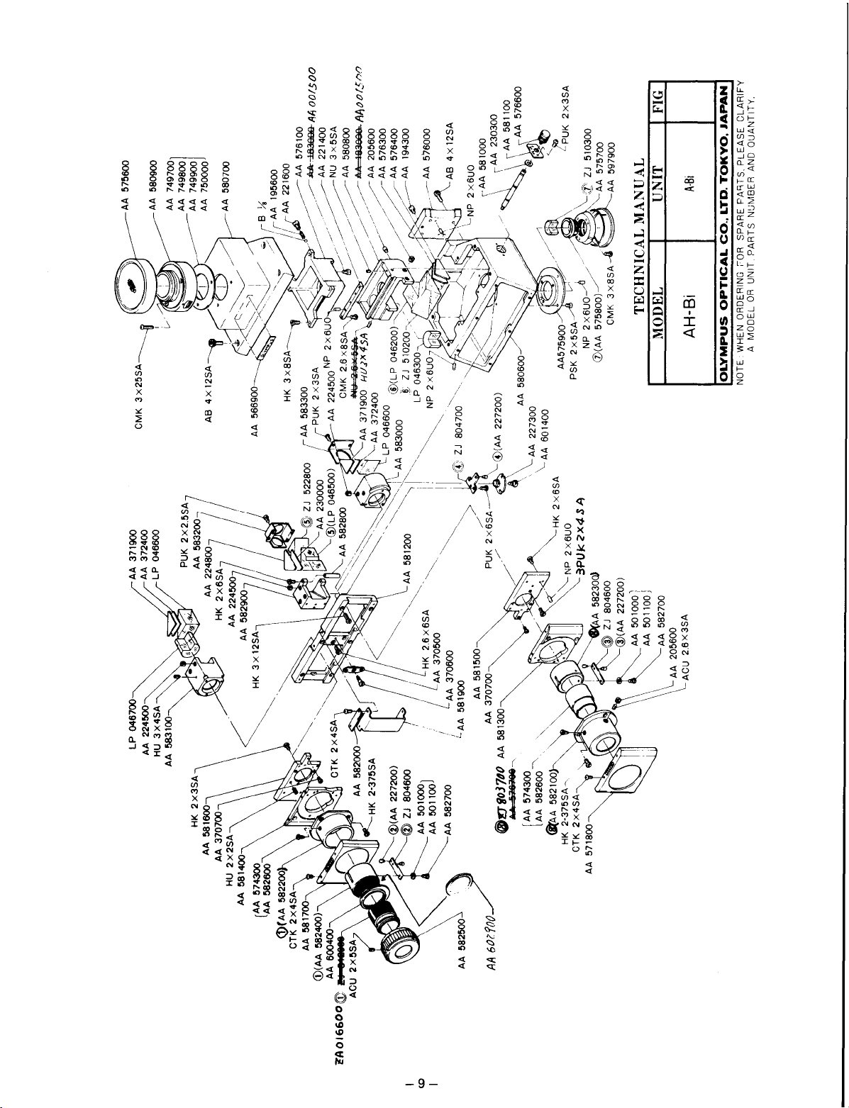
A·Si
UNIT
IINICAL MANUAL
TEe
AH-Bi
MODEL
,,'"''
AA 205600
ACU
\
CLARIFY
JAPAN
QUANTITY.
PLEASE
AND
TOKYO.
PA'iTS.
LTD.
CO.,
UNIT. PARTS NUMBER
OR
OPTICAL
ORDERING cOR SPARE
A MODEL
WHEN
OLYMPUS
NOTE
\~
1 ,
..
2X5;7
J 811
fD
~AOI6600~C~
I
I
cc
Page 13
A
AA
58500~
NP 1.6 x
6UO~
AA
T AA
B
585000------"t
584400~
,V
NP
c
1.6X6UO
o
~
-r.'
.....
;
. CSK
~
1
AA
56960~
::
:::=-=~.c
'WiZJ
803000-~~
CD(AA
584600)----
...------
PSK
2X4SA--------·
AA 58670 »
CUK 2.6X
2
5SA___________
AA 571000
~
--->'~~":::::::'==--
AA 583600------
AA 583700
AA586300~
AA
",,"0
-------------
/
:-.--,!,
~
"'DI
..
~
:-:
AA
~::
r.
2.6x6SA
__
G?
.
""=---------:::: , AA 259500
0/
}JU
..
"oo]
~:::~~
~.
~AA
r
i"
CSK
AA
~A
062500 '
-~:'
----'Y"
.
~
~if
~
'.•"
•
~~:A,,"497800
(
https://manualmachine.com/
'-=-'
't1
/'
A
...:.
AA
S'rllOOJ
AA 584900 •
..
~::~o.0"~>AA5"/
~".
"~~~.
"''''''.''~.....
'.,
26~6SA
571100--
~HU
v""
~
//
/
/
~;~bA~
~
~..~:
CUK
2.6x5SA
26x3SA
""/
_~HK
/AA
/'
/'
rCUK
/ /
//NP.2XHUO
q
~~~AA584300
//
~~
/'"
'.
~.,
~.
AA 585100
3 x 4SA
584000
2.6x8SA
586200
L::<.
....
"-."
...
~AA584000
"-
""
~
"
'""
"-NP
""--B
~
'-
"--AA
V.
t..
1.6X60UO
%
NP
1.6x5UO
AA 584000
584200
AA 585200
AA 793300
AA585~00
V AA 960900
tAA.585400
AA
585500
_
CA::::~~AA":90
NP1.6X50https://manualmachine.com/
1.6x6UO
NP
AA 583800---------------
3
--
3X8SA-
CUK
AA 500900
AA 501000
AA 501100
[
AA 501200
AA 19860
4
c'·
)-
~
.""'---_.=::::::'~~
-~''-'--
0
~_~~~=~~K~~::A
~------=---------AA
AA 198600 U
I
'\AA
7
!
AA
[
-~
211900
\
\AA601700
\
NN3BA
.
~rA2~:26XOSA
https://manualmachine.com/AA019900
364000 •
AA
50130/~
AA 501400
AA
501500
AA 50160
OLYMPUS
NOTE: WHEN ORDERING FOR SPARE PARTS,
A MODELORUNIT,
----------NP2·6UO
-~CUK
~
""'-
EXPLODED
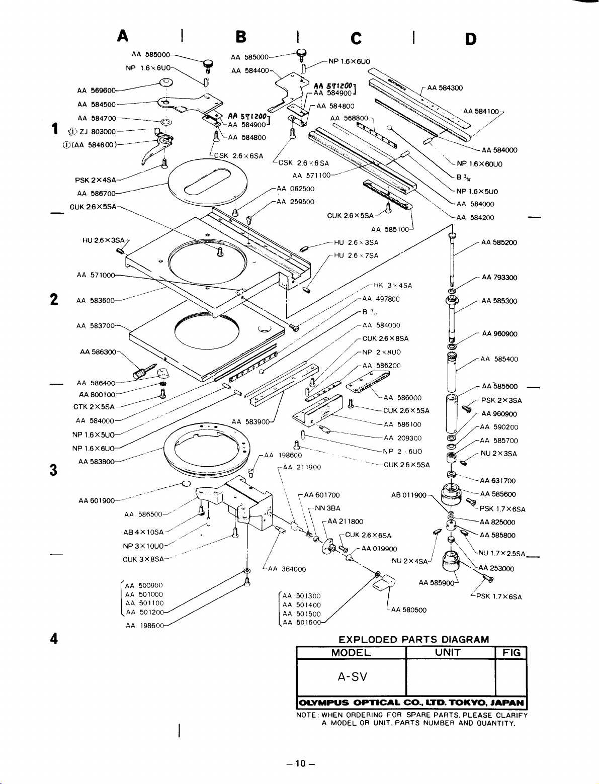
MODEL
A-SV
OPTICAL
209300
2.6 X 5SA
AB011900-V
NU2X4SA-!"
LAA580500
PARTS
CO.,
PARTS
~::=
https://manualmachine.com/AA
~
'"
~~''''''''''''AA
'"
~PSK1.>X6SA
r
~,~::=
I
~'
""
~~
AA585900
DIAGRAM
UNIT
LTD.
TOKYO,
NUMBER AND QUANTITY.
585700
/NU2X3SA
631700
~AA585600
\.NU
1.7X25SA_
•
r53000
LPSK
1.7X6SA
FIG
JAPAN
PLEASE
CLARIFY
-10
-
Page 14
(D(LA
@
LA
AA
AA
AA
AA
572800
ZJ
427600
381000
573400
564100
I
427800)
5100QO
PUK
2x8SA
AA
573600
AA
ACU
AA
LA
AA
LA
AA
AA
AA
~
572600
2.6
573100
572900
573000
X4SA
427500
427500
573200
427500
~
j
SA
TE
CHNICAL MANUAI.
.------;;l\~I(~)lj)")
RE
IL~
~
UNIT
--,
I
F~
AH-AL
A-AL
1 _
AL
co.,
LTD.
TOKY
0,
LYMPUS
o WHEN ORDERING
NOTE A
OPTIC
MODELORUNI .
PARE
~Op~~TS
PARTS.
NUMBER
AND
PLE
ASE
QUANTITY.
JAPANJ
CLARIFY
-11
-
I
Page 15
CLARIFY
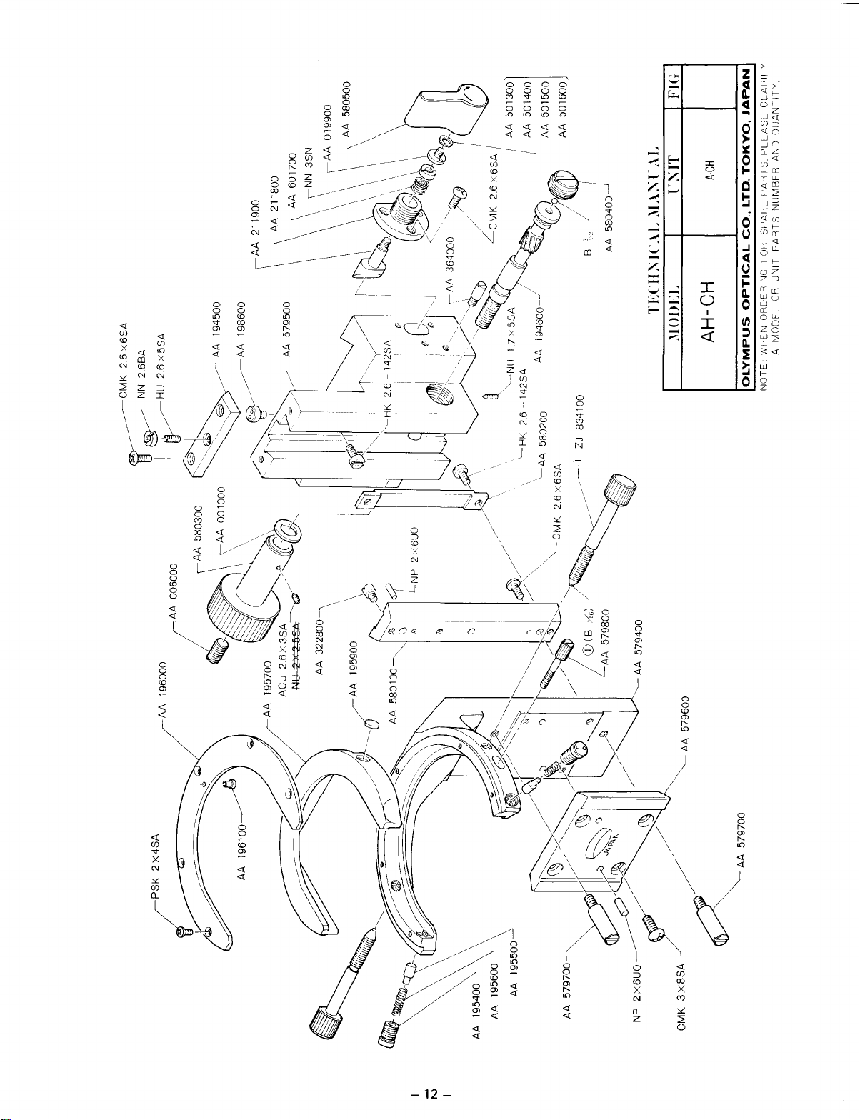
A·CH
I I
JAPAN
YO.
TOK
LTD.
..
I
CO
OPTICAL
OUANTITY.
PLEASE
AND
PARTS.
NUMBER
SPARE
PARTS
FOR
UNIT.
OR
I
C:\IT
580400.J
AA
B
J
:\L\:\L\L
I
TECII:\IL\L
AA
2x4SA
580100~,
AA
!
l)1
~'"
194600-
NU
142SA
--
2.6
f<K
L
, ''---
jJI
834100
580200 AA
ZJ
26x6S'
MK
•
~
~/
,"--C
J
I'
."
I,
....
~8
//
'
~:~-
''1'(;)
I~
)Cl
579BOO
CD<s
AA
~
/_
I Q
~~,II
/~:
\':)
"'~~
P~~
-
~"
~I~
:\IODEL
AA 579600
I '------AA 579400
/\Il
/'
AH-CH
MODEL
A
WHEN ORDERING
OLYMPUS
NOTE
AA 579700
rPSK
I
i~~
~
._
~
AA 195500
AA 195600
AA 195400
I
I'V
AA 579700
3XBSAJ
2X6UO~~
NP
CMK
~.
Page 16
A
B
CTK2X5SA--
2.6X
CTK
5SA i --i
c
_
D
: Refer to
exception
ustrated here.
1
AA9~:10~65OO--------~1
AA 954200
CTK
OF
0047 \
<For
2
OF
0048
<For
OJ0234
3
E80071:f€ol
ES
EL
0028<For
EL0029<For
-
A-B-2
with the
of
those illustrated
~
I~--I~:::::
EV~'
<For looV>
<For
2OOV>
~-\
3X5SA~
OF
looV>l
2OOV>
/ID'~
.
~K
.
~
0072(1"'01
AA 953200
CUK2X4SA-~'-~_~:
CUK
:"~,,,
0046,
~1
LY-~
https://manualmachine.com/
<1Y~~~For
~
JZ:?;;
I?
~It"-
/
-)!
/ AA 9534oo<For 200V>
~
~
~
CTK 3X 5SA I
DW0041
200",;~~wf
100''1')
lOOV>
200V>
BNW
3SA-----
sw
3SA
3X5SA
I~I~~II~
/~/
~I/
""
,
~
I
"",
'l1
CUK
~;)
'
~'~~
I
'\J.' I
OFdo20.
<For looV> I( \
OF0049"'---~~'
200V>~
~~5
OS
OS
AA 953300<For
3 X 5SA "
AA800300~
OW0015~
CUK3X5SA
AA
952800-
~r",~,,&,,~~,
_,,--
~
,~>
--
__
--
~
~~~~
I.Av'i'
~-
)8
~
/ACU
I,:
'~~
I
oo95<For
0096 <For 200V> <
J~"~l/
~.
//
2.6X4SA
AA650000
~a"~
/ I
lOO\;>
100V>
~
-
/!'
/
J'
/
/~'
<
6N
6SA)
• I
~
I~/i
J (I
J.
I
.....
~/,
~
-/,
1.
----/
1
~~."'-.....~
I/I~
~;;r--'
I
1:
---------=
/
X'4t61
~
w
I
«,
~
",
//.
./
~
~
6N3SA
""J~"
'-
~,'l"-
"-.
'~'~~,"'b
DJ
0225
AA
CUK
f
~
/
~;
I:
..
::e>
V"//
\~A'"
if;/
® ! t .
/
Y/
I
l~i
~
/'
_/ _ . . '
,.
~~
~~-·"~·'--AA957lO0
'"
V
~
~
~~
/i.';
:::
~
~/~
~~
~
~
OJ
0063 '
~
~
;YJ<
'
,l~
."5<
649900
"~~_,
.../
3X 8SA
I Y
~
~
/1 /
V
.CUK26X~SA
i~~
'~,:
~
.d<J
'A')
/"
~AA
SW
\
'''
~
"<'0'
~
.....
~
,I
~
~:::~~::=
,~~
SW
CUK
//~/
//
~
~.
~~,
11
~-_~~DWOlll,
~'-',,-
~
~
~"'~
'",,~DWOlO9
957000
4SA
AA 953700
OB
0054
OK
0020
CUK
3X5SA
AA 952700
EL
0030
<For 200V>
EVOOO8
OS
0142(For
OS0143(For200V)
AA 953600
~
~
~
-
"
'-.....
...
i'."c-CTK3X5SA
~'N
~'-.....~CTK3X5SA
~AA7464oo
~<&@l~CUK2.6X4SA
~
'---AA
745800
ACU2.6X4SA
~~CTK
--~
4SA
/1
_________
4X6StJ AA 953500
w 1"
y
/AA952900
3X
-CUK3X5SA-
AA953000
~
1
UYPC45
<For
UYPC36
~~cu~o~
3 lOSA
DJ
0227
DW0073
'.-~/~AA953100
RY
0232
~
DW0015
~CUK3XlO~
//~6N4SA
1
4
AA 954000
CUK3X5SA~
AA 594400
G)
I=-~
/
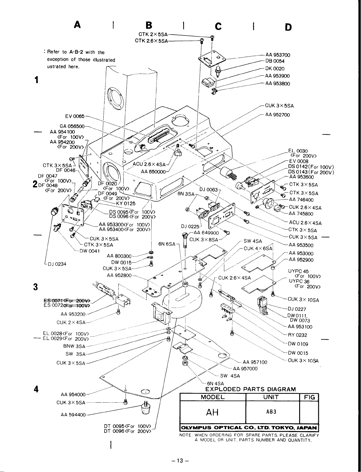
EXPLODED
MODEL
AH
PARTS
DIAGRAM
UNIT
A-B-3
lOOV)
5SA
lOOV>
200V>
FIG
OT
0095<For looV>
OT
0096<For
2OOV>
OLYMPUS
NOTE WHEN ORDERING FOR SPARE
A
-13
-
OPTICAL
MODELORUNIT.
CO.,
PARTS
LTD.
TOKYO,
PARTS.
NUMBER AND
PLEASE
JAPAN
CLARIFY
QUANTITY.
Page 17
Jl0l
L
E
IINLET I
J
102
Hl0l
(~Fl01)~
Hl02
RC101
r--------
.--------+-------+0
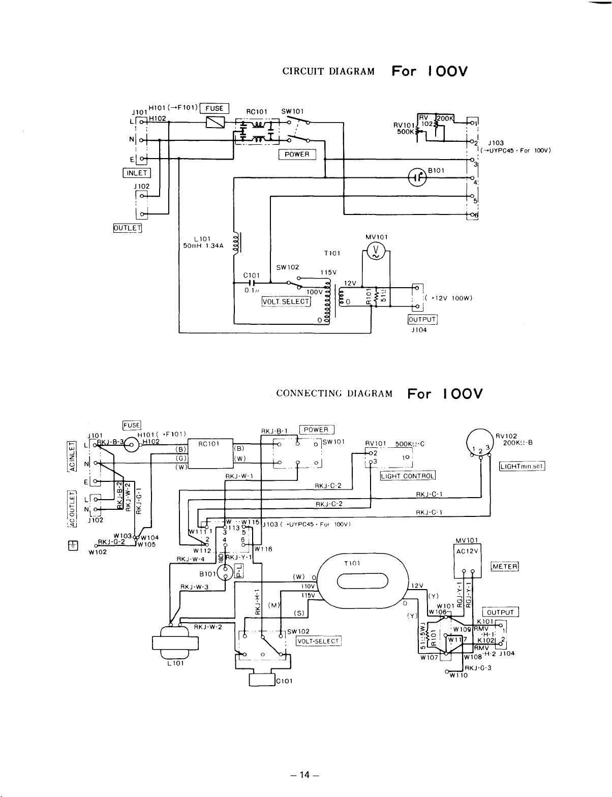
CIRCUIT
SW101
DIAGRAM
.......
-+------+1
For
RV101
500K
IOOV
'--
.....
--+<>2
t-r----;-04:
1
J103
I
(~UYPC45'
31
1
5
For
l00V)
~
E
L
N
L
~
(J,
Jl02
~~
Wl02
.
RKJ-G-2
\FUSE-[
Wl03
Hl0l(-Fl01)
Hl02
Wl04
Wl05
(B)
(G)
(W)
50mH
L101
RC10l
134A
(B)
(W)
RKJ-W'l
C10l
01/,
§i£Sfu@
i
;;:
er:
MV101
TlOl
SW102
115V
100V
o
CONNECTING DIAGRAM
I POWER I
RV101
0J
RKJ-C'2
RKJ-C-2
·UYPC45·
(M)
(5)
For lOOV)
C
__
Tl01
For
500K~'-C
2'~
3
1°'
.. _ J
[UGHTCONTRQb]
RKJ-C-1
RKJ-C-l
)
lOOW)
IOOV
1 2 3
MV101
AC12V
RV102
200K~!'B
-14
-
Page 18
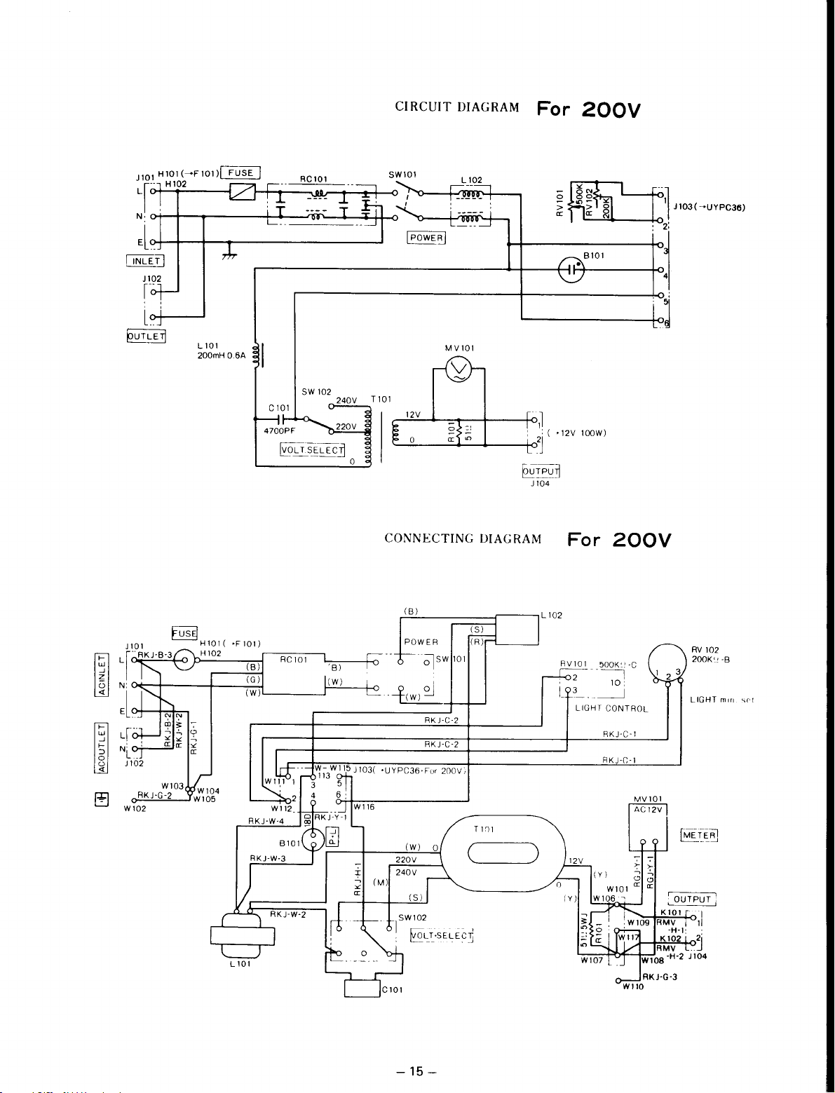
CIRCUIT DIAGRAM
For
200V
~
Jl02
,--
lo-
__
1----
L101
200mH
06A
C
101
4700PF
§""0_
5W
S
102
EC-
o
>
a:
--------+<>""
MV101
T
101
240V
~~~:-t---r----t<JJ
~
L
E
c2J
o
__
I-------t<-'2J
CONNECTING DIAGRAM
: (
-12V
100W)
~T~LJ~
Jl04
For
200V
--~
J103(~UYPC36)
~
~
W103
__
Hl01(
H 102
WI04
W105
Jl0l
O'-R_K-,"J~-G~-~2
W102
-F101)
(W)
r------;::-R:::-C"7C10::-:
(B)
(C)
:--""l,--
1
__
-r-o
'!'
><
a:
r(!.!:B~)~-----;=:::;:;::;:::r--1
POWER
--~5W
101
-t-
0 I
-(W)
'::'J
RKJ-C-2
RKJ-C-2
-UYPC36'For
220V
240V
(M)
5Wl02
I
200V)
T
I~I
(W)
(5)
(
§:LT'5EU:C~
L 102
RV
102
200K',
-B
1 2 3
LIGHT
min.
LIGHT
CONTROL
RKJ-C-'
RKJ-C-l
MV101
AC 12V
)
W110
':"
CO
a:
RKJ-G-3
0;-
':"
CO
a:
se!
-15
-
Page 19
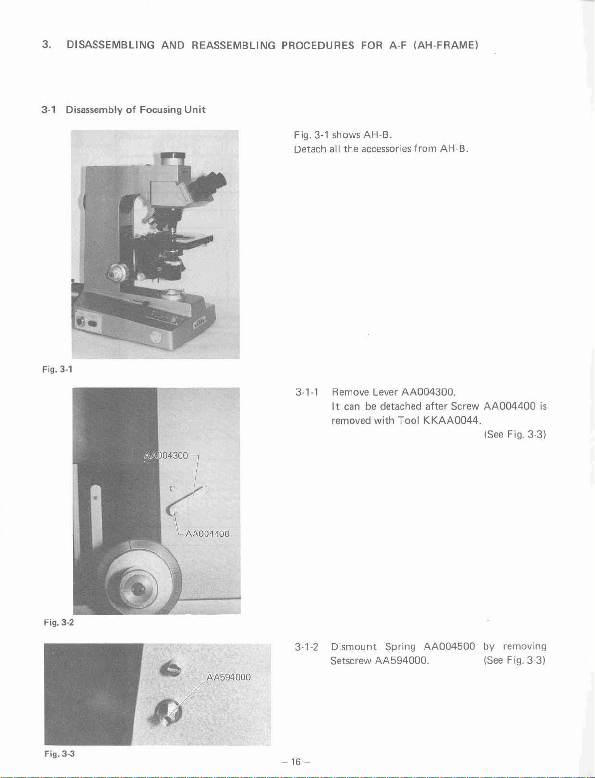
3.
DISASSEMBLING
3-1
DisassemblyofFocusing
AND
REASSEMBLING
Unit
PROCEDURES FOR
Fig.
3-1
shows AH-B.
Detach
all
the
accessories from AH-B.
A·F
(AH·FRAME)
Fig.
3·'
0430°7
(04400
AA5940QO
3-1-1 Remove Lever
It can be detached after Screw AA00440Q
3·'·2
removed
Dismount
Setscrew AA594000.
with
Spring
AA004300.
Tool
KKAA0044.
AA004500
(See Fig. 3·3)
by
removing
ISee Fig.
3-31
is
Fig.
3·3
-16-
Page 20
Fig. 3-4
I Arm
l.v
AB5x20SA
3-1-3 A
carefully remove
her
removing
mount
Now, the focusing
from
inserted
Fig. 3-5, slightly incline the focusing
Fixing Plate AA579300.
Arm
into
six
Screws AB5x2OSA, dis-
(See F
unit
can
be
disassembled
AA583400. Since the spring
the topofthe armasshown in
it.
(See
i9.
unit
Fig.
3-4)
is
and
3-51
Fig. 3-6
rZJ812600
AA592500
3·1-4
3-1-5
Remove Spring
812600.
After
Spring
593900 downward.
removing Stopper AAOO1500, pull
AA593800
AA592500
and
Spring Housing
(See
and Belt ZJ-
(See F
Figs.
i9.
3·51
out
AA-
3-6, 3-7)
Fig. 3-6
-17-
Page 21
\W'I'!1I'7!«1
1(j\YIfO'N'IrII
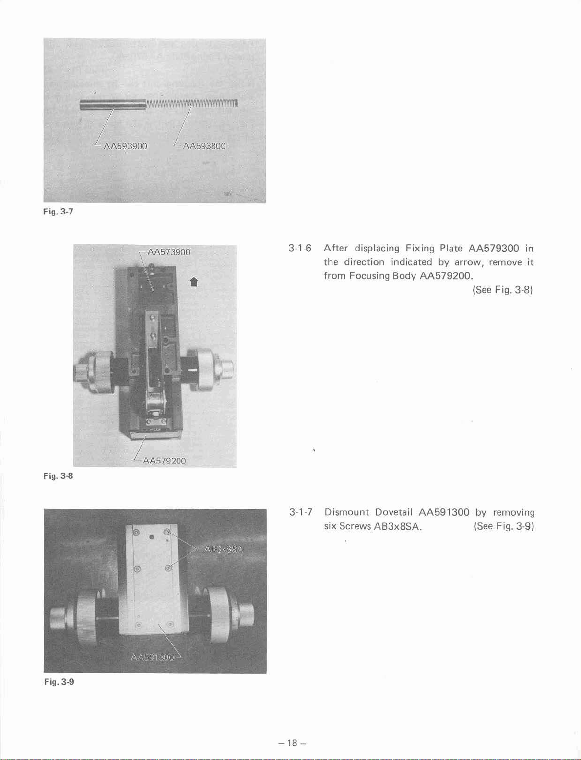
Fig. 3-7
7A59390~
,AA573900
AA593BOO
3-1.ti
After
the
from
displacing Fixing Plate
direction indicated by arrow, remove
Focusing Body
AA579200
•
AA579300
.
(See
Fig. 3-BI
in
it
Fig. 3-8
Fig.J-9
AA579200
-18
3-1-7
-
Dismount
six Screws AB3xBSA. (See Fig. 3-9)
Dovetail
AA591300
by removing
Page 22
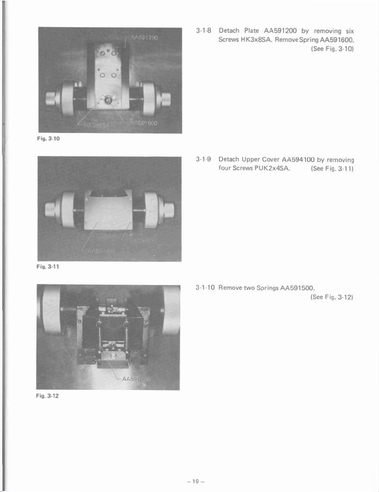
Fig. 3-10
3·1..B
Detach
Screws
Plate
AA591200 by
removing
six
HK3x8SA. RemoveSpringAA591600.
ISee Fig.3·101
Fig. 3·11
3-1-9
3-1-10
Detach
four
Screws
Remove
Upper
PUK2x4SA.
two
Springs
Cover
AA594100
AA591500.
by
removing
(See
Fig.
3·11)
ISee Fig. 3·121
Fig.
3-12
-19
-
Page 23
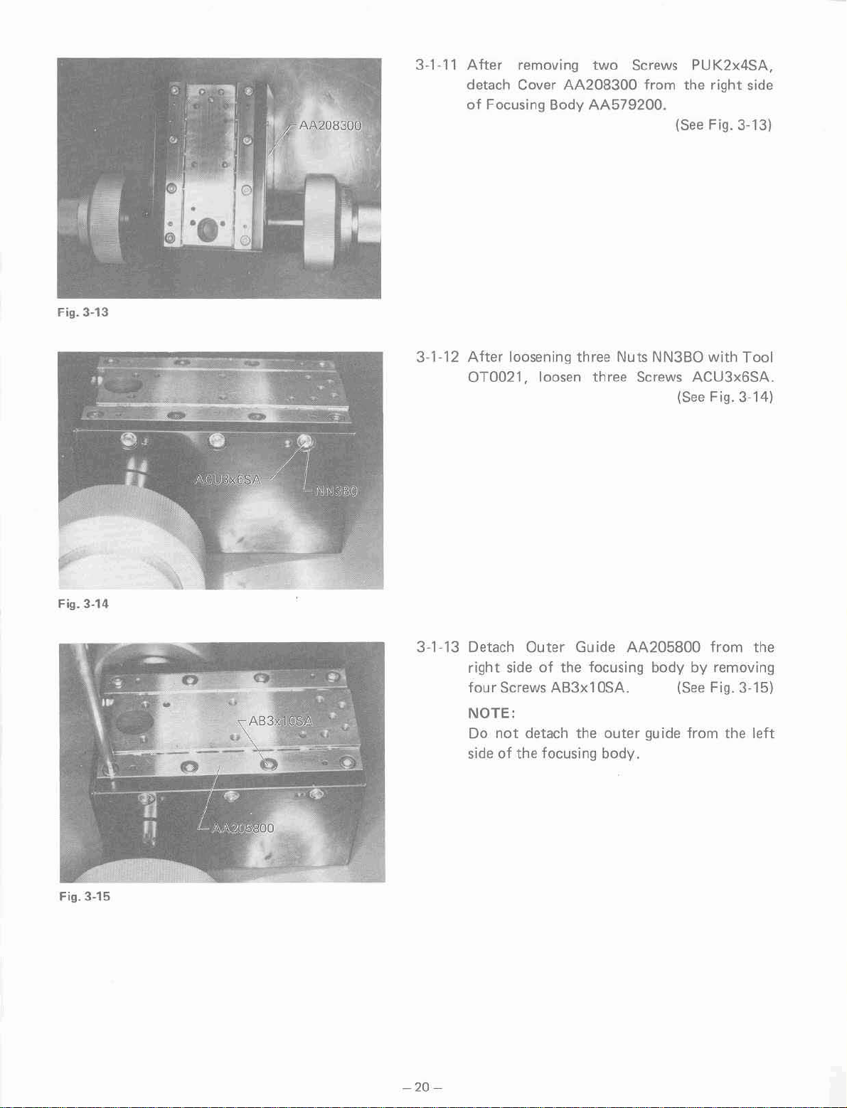
Fig. 3-13
3-1·11
After
removing
detach Cover
of
Focusing
two
AA208300
Body
AA579200.
Screws
from
PU
the
(See
K2x4SA,
right
side
Fig. 3-131
Fig_
3-14
3-1-12
After
OT0021,
3-1-13 Detach
right
four
Screws
NOTE:
Do
not
sideofthe focusing body.
loosening three Nuts
loosen three Screws
Outer
side
Guide
of
the focusing
AA205800
AB3x10SA.
detach the
outer
NN3BO
with
ACU3x6SA.
(See
Fig. 3-141
from
body
by
removing
(See
Fig. 3-15)
guide from the
Tool
the
left
Fig. 3-15
-
20-
Page 24
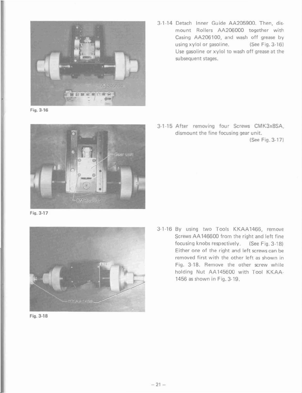
Fill. 3-16
31·14
Detach Inner Guide
mount
Casing
using
Use
subsequent
Rollers
AA206000
AA206100,
xylolorgasoline.
gasoline or
xyloltowash
stages.
AA205900.
and
wash
Then, dis·
together
off
grease
(See
Fig. 3-16)
off
greaseatthe
with
by
Fill.
3·17
3·1-15
After
removing
four
dismount the fine focusing gear
3·1·16 By using two Tools
Screws
AA
146600 from the right and
focusing knobs respectively.
Either oneofthe right and
removed
first
with
the other
Fig. 3·18. Remove the other screw
holding
Nut
AA
145600
1456asshown in Fig. 3-19.
Screws CMK3xSSA.
unit.
(See
Fig.3·17)
KKAA1466,
(See
left
screws can
remove
left
fine
Fig. 3·18)
be
leftasshown in
while
with
Tool
KKAA-
Fig.
3·18
-21-
Page 25
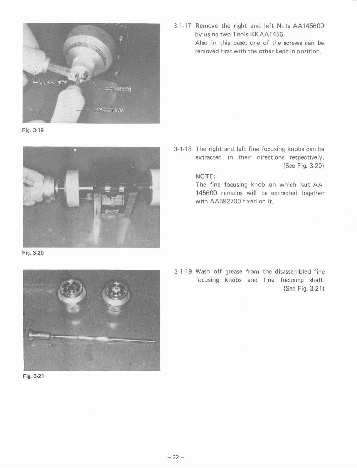
3-1-17 Remove
by
using
Also in this
removed
the
two
first
right and
Tools
KKAA
case,
one
with
the
left
Nuts
1456.
of
the screws can
other
keptinposition.
AA145600
be
Fig. 3-20
3-1-18 The
extracted in their directions respectively.
NOTE:
The
145600 remains
with
3-1-19
Wash
focusing knobs and
right
and
left
fine
focusing knob on
AA592700
off
grease
fine focusing knobs can be
ISee Fig. 3-201
will
be
fixedonit.
from
the
fine
which
extracted together
disassembled
focusing shaft.
Nut
ISee Fig. 3-211
AA-
fine
Fig. 3-21
-22
-
Page 26
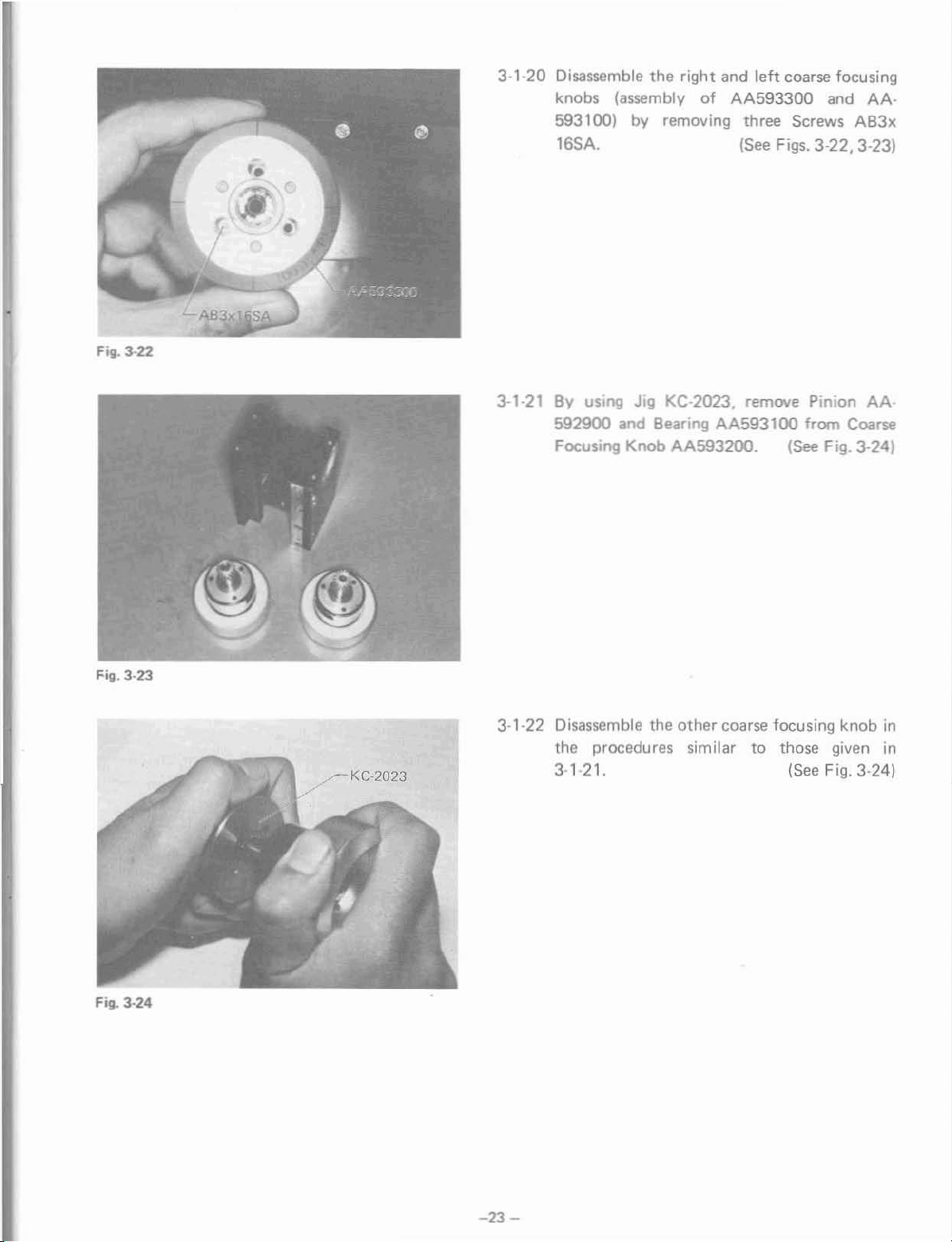
Fig. 3-22
3-1-20 Disassemble the right and
knobs (assembly
of
AA593300
593100) by removing three Screws
16SA. ISee F;gs. 3·22, 3·23)
left
coarse focusing
and
AA-
AB3x
Fig. 3-23
....---KC·2023
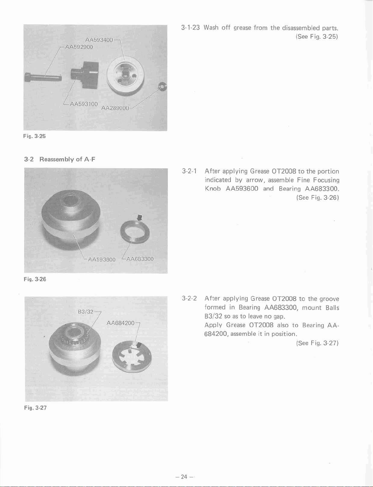
3-1-21
BV
using Jig KC-2023. remove Pinion
592900 and Bearing
AA593100
Focusing Knob AA5932(Xl-
from Coarse
(See
Fig.
3-241
3-1-22 Disassemble the other coarse focusing knob
the procedures similar to those given in
3·'·21.
(See
F;g.
3·241
AA·
in
Fig.
3-24
-23
-
Page 27
(AA592900
AA593400
3-1·23
Wash
off grease from
the
disassembled parts.
(See Fig. 3-25)
L.AA593100
Fig. 3-25
3-2 Reassembly of A-F
\...
AA593600 LAA683300
AA289000/
3-2-1 After applying Grease OT2008tothe
indicated by arrow, assemble Fine Focusing
Knob AA593600 and Bearing AA683300.
(See Fig. 3-26)
portion
Fig. 3-27
83/32
3·2-2 After applying Grease OT2008tothe groove
formed
in
Bearing AA683300,
mount
83/32soastoleave no gap.
Apply Grease OT2008 also
684200,
assemble itinposition.
to
Bearing
ISee Fig. 3·27)
-24
-
Balls
AA-
Page 28
Fig.
AA5 3600
3-28
~AA145600
3-2·3 After applying a thin
to Nut
AA
145600, assemble it with left Fine
coat
of Grease OT2008
Focusing Knob AA593600. (See Fig. 3-28)
3-2-4 Assemble the right fine focusing knob
similar procedures.
in
the
Fig. 3·29
rAA592900
AA593100
.......
AA143200
3·2·5
After applying Grease OT2008
tions indicated by arrows, assemble Pinion
AA592900
and Bearing AA593100.
ISee Fig.
3-2-6 After applying Grease OT2008
AA593400 and
143200
(at the portion
AA
indicated by arrow), assemble Pinion
592900 by using Jig KC-2023.
NOTE:
Make sure that the pinion can
ISee
to
to
turn
Fig. 3·301
the
por-
3-291
Bearing
AA-
smooth.
Fig.
3-30
3·2·7 Assemble
ing knob.
-25
-
the
other
pinion and coarse focus-
Page 29
AA593400
AA593100
AA592BOO
AA143200
AA592900 having smaller diameter
AA592800 having larger diameter
3-31
Fig.
AA593300
3-2-8 After Nut AA289000 has been tightened
sufficiently, right Coarse Focusing Knob
AA593300 (with graduations engraved) must
in
turn smooth with no play
the
direction. (See Fig. 3-31)
AA28900a
thrust
Fig.
3..:32
AA593300
AA593400
KC·2002
AA593400
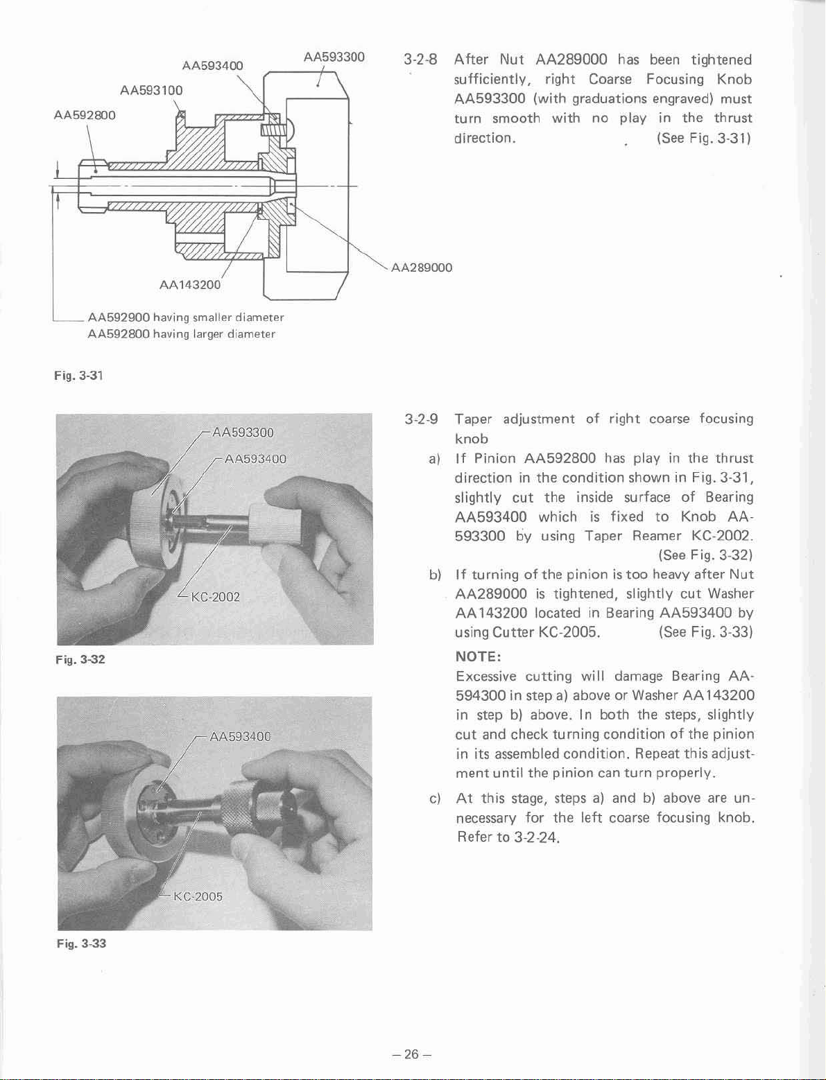
3-2-9 Taper adjustment of right coarse focusing
knob
a)
If Pinion AA592800 has playinthe
direction
slightly
AA593400 which
593300
b)
If
turning of the pinionistoo
AA289000
AA
in
the
condition showninFig. 3-31,
cut
the
inside surface
is
fixed
by using Taper Reamer KC-2002.
is
tightened, slightly
143200 locatedinBearing AA593400 by
to
ISee F;9. 3·321
heavy after Nut
of
Knob
cut
thrust
Bearing
AA-
Washer
using Cutter KC-2005. (See Fig. 3-33)
NOTE:
Excessive cutting
will
damage Bearing
AA594300instepa)above or WasherAA143200
in
step
b)
cut
in
its assembled condition. Repeat this adjust-
ment
c)
At
necessary for
Refer
above.
and check turning conditionofthe
until the pinion can turn properly.
this stage, stepsa)and
to
3-2-24.
the
In
both the steps, slightly
b)
above are un-
leh
coarse focusing knob.
pinion
Fig.
3..:33
-
26-
Page 30

Fig. 3-34
3-2-10 Operation checkoffine focusing gear unit
a)
When forceisapplied from above as shown
Fig. 3-34, the sector gear should normally
or
turn smooth with no seizure
bl Apply Grease OT2008
(B
1/8) and watch oil OT 1037tothe gear
to
play.
the
operating point
bearing. (See Fig. 3-34)
cl
Attach
the
gear unit
to
Focusing Body
AA579300 with four Screws CMK3xSSA.
3-2-11 Fix the right and left coarse focusing knobs
to
Focusing Body
AB3xl6SA
AA579200
with six Screws
(three screws for each knob).
(See Fig. 3-35)
NOTE:
Figs. 3-35 through
ing knobs assembled
they are
of
not
set actuallyincorrect conditions
the reassembling steps.
3-46 show
in
position. Hovvever,
the
fine focus-
in
Fig. 3-35
Fig. 3-36
3-2-12 Apply Grease
205800.
OnOl0
to
Outer
(See Fg;g. 3-361
Guide
AA-
-27
-
Page 31

AA205900
Fig. 3-37
3-2-13
Apply
205900
Grease
(at the
OT2010
portion
to
Inner
indicated by arrow).
Guide
(SeeFi9.
AA-
3·37)
•••
• AA206100
• •
Fig. 3-38
3-2-14
3-2-15 Stand
•
•
With
the
left
Outer
downside on the focusing
AA206100
206000.
The rollers should
opposite directionsasshown in Fig. 3-38.
Fig. 3-38 and
describedin3-2-14.
NOTE,
See
toitthat
posite
manner
and arrange eight Rollers
up
Inner
the
to
each
as
shown below:
~,"-
L0
Guide
be
arranged alternately in
Guide
mount
AA205900asshown in
the casing rollers
right
other,
A_A20_5_9_0_0
A_A_2_05_9_0_0
AA205800
body,
mount
(See
Fig. 3-38)
and
left
rollers, op-
be
assembled in a
~
Q]
kept
Casing
AA-
as
L
__
A_A_2_o5_9_o_o_-!
AA579~
FiG.
3-39
D AA206000
@
AA205800 {Fixed outer guide)
@
/AA205800
__
O
__
@ @
3-2-16
---lG~oo,OO
3-2-17
~
Mount
guide on which
arranged
Fig. 3-39. Place the inner
of
Temporarily
tightening
Outer
the focusing guide.
Guide
the
to
setitin the
fix
four
Screws
Outer
AA205800
rollers have already
AB3x10SA.
on the inner
condition
gUide on the guide
Guide
shown in
(See
Fig. 3-39)
AA205800
(See
Fig. 3-39)
been
by
Page 32

Fig. 3-40
3·2-18 Adjust the
screws
and
nuts listed below
Inner Guide AA205900 drops slowly by its
own weight when Focusing Body
is
inclined atanangleof45°.
a)
Lightly tighten Screw
bl
Tighten
and
adjust Screw ACU3x6SA.
c) Tighten Screw AB3x1OSA
AB3xl0SA.
firmly.
d) Check for the item described in 3-2-16.
e)
Tighten Nuts NN3BO.
AA579200
(See
Fig. 3-40)
until
Fig. 3-41
3-2~19
Set
3-2-20
PUK2x4SA.
two
Springs
Fix
Upper Cover AA594100
AA591500
with
in position.
ISee
Fig. 3-41)
four
Screws
(See
Fig.
3-421
FiG.
3-42
-29-
Page 33

Fig.
3-43
3-2-21 Attach Plate
with
six Screws HK3x8SA. Assemble Spring
AA591600
AA591200tothe focusing body
in position.
(See
Fig. 3-43)
Fig.
344
,
~.~-l
3-2-22 Attach Dovetail
body
with
six Screws AB3x8SA.
3-2-23
Apply
of
consisting
Plate
initial conditions.
Grease
the focusing body and
of
Dovetail AA591
AA579300.
AA591300
OT2022tothe female dovetail
Assemble them in their
to the focusing
ISee Fig. 3-44)
thatofthe assembly
lOO
and
Fixing
(See
Figs. 3-45, 3·46)
•..,f1l III
.
,~-
Fig.
345
-30
-
Page 34

3-2-24 Adjustmentofcoarse focusing tension
a)
Grasp the right and left coarse focusing knobs
in
the
conditions assembledin3-2·23. While
fixing the right coarse focusing knob, turn the
left coarse focusing knob clockwise (in
tightening direction).Inthis condition, check
the coarse focusing knob for its rotation
tension (manual feeling).
Then, turn the
leh
coarse focusing knob
counterclockwise (Iooseing direction) and
check
tion tension. It should normally
the
coarse focusing knob for its
be
than felt previously.
NOTE:
For checking the coarse focusing knob for
fix
its rotation tension,
may be grasped by hand) and
the focusing body (it
tu
rn the
coarse focusing knob.
b)
If
the
turning
rotation tension
the
left coarse focusing knob clock-
cannot
be varied by
wise, disassemble the left coarse focusing
cut
the
knob and slightly
inside surface of
Bearing AA593400 by using Taper Reamer
KC-2002.
(See
cl If the coarse focusing knob turns extremely
heavily after the left coarse focusing knob
turned clockwise, disassemble the
focusing knob and slightly
cut
leh
Washer 143200
with Cutter KC-2005. (See 3·2-9-bl
the
rota~
lighter
leh
3-2-9'01
is
coarse
Fig. 3-46
3-2-25 Adjustment
pinion
Aher
be rotatable as lightly
thatitis
at
the upper, intermediate and lower positions
of
the
If it plays
below:
a)
Remove one
Check
b)
When
insert a piece
under
cl If
the
file off
-31
-
of
engagement between rack and
setting
the
coarse focusing knob so as to
as
possible, make sure
free from play (backlash)orgrating
coarse focusing range.
or
grates, adjust
of
the two Racks AA593000.
the
other rack.
the
coarse focusing knob has play,
of
tin foil (t=:0.01to0.05 mm)
the
rack.
it
as
described
coarse focusing knob grates, slightly
the
bottom surfaceofthe
rack.
Page 35

NOTE:
For
filing
off
the
bottom
surfaceofthe rack,
lay a sand paper on a flat surface (stool
similar device) and place
Then, move
top
surfaceofthe sand paper.
d) Disassemble
properly. Reassemble
out
stepsb)andc)above.
the
rack back and forth along
the
rack which has been adjusted
the
other
the
rack on it.
rack
and
or
carry
the
the
ZJS12600\
Fig.
347
,AA592500
3·2·26 Assemble
the
knobs (either
focusing shaft).
KKAA
1466isunnecessary. Screw
knobs by
firmly.
3·2·27 Apply Grease
Roller AA591900.
position and
with Screw AA592000 located on Fixing
Plate AA579300. ISee Fig.
right and left fine focusing
is
equipped with
For
this purpose, Tools
both
both
hands and tighten
OT2008
hook
to Belt
Set
Spring AA592500
the
other
ZJ812600
endofthe
the
fine
the
them
and
in
spring
3-47)
Fig. 3-48
3·2·28
3·2·29
-
32-
After applying Grease
OT2008
to
Spring
AA593800, insert it into Spring Housing
the
AA593900 and assemble it with
plate.
In
addition, attach
Stopper
ISee Figs.
Now,
the
coarse focusing
unit
fixing
AA001500.
3-48, 3-49)
has been
reassembled. Assemble it with Arm AA·
583400
and fix it with six Screws AB5x2OSA.
ISee Fig.
3-4)
Page 36

Fill. 3-49
AA0015QO
Fig. 3-50
AA277400
=
AA004500 AA594000
1 -
AA004400
AA004300
AA004300
-(
AA903100
3-2-30 Apply Grease
Screw
Assemble them with Arm AA583400.
AA594000
X
AA2174~@>
AAOO4500
Fill. 3-51
3-2-31 When
the
stopperislocked, Lever AAOO3400
is
located within
(Lock the stopper with AA004400.1
NOTE:
AA004300 and AA903100 should be used
selectively.
OT2008
AA594000
AA004300
AA9Q31
the
to
the
and Spring AA004500.
(See
Figs. 3·50, 3·511
AA583400
AA322BOO
J"~
00
AA004400
range showninFig. 3-53.
threads
.7
of
Fill. 3-52
@
AA004300
-
33-
@
AA903100
Page 37

Fig.3.s3
Lever
this
range
locked.
must
be
when
located
the
stopper
wIthin
is
3-3 AdjustmentofFine Focusing
Fig.3.Q4
Range
3-3·'
3·3·2
Make sure that the fine
movable
ing Body
within
the
AA579200
range
and Plate AA591200.
fOOJsing
engraved on
knob
Fows·
Pushing down AA591200, turn the fine
fOOJsing
Upper
Lower
When
beyond the upper and/or lower
Setscrew NU3x8SA (indicated
knob.
AA579200
limll
limit
Fig. 3·55
~AA591200
the fine focusing knob
(See
limit,
by
Fig. 3-54)
is
movable
loosen
arrow)
and
adjust vertical positionofScrew AA631900.
Aher
adjustment, tighten Setscrew NU3x8SA
(See
firmly.
Fig. 3-56)
is
Fig. 3-56
-34-
Page 38

4. DISASSEMBLING PROCEDURES AND FOCUSING AND OPTICAL
(BINOCULAR TUBE)
4-1 DisassemblyofA-Si
Fig.
4-1
shows
Fig. 4-1
A-Bi.
ALIGNMENT
OF A·Bi
Fig.
4-2
\A581800
,AA581700
4·1-1
4-1-2 Detach
By
removing three Screws ACU2x5SA.
assemble
removing four
cover.
Detach
581900 by removing four Screws CTK2x4SA.
Diopter
Covers
Scale
Ring
AA58170Q
Screws
Plate
AA582000
AA582500.
ISee
and
AA581800
CTK2x4SA from
and
Cover AA-
ISee
Figs.
dis-
Fig.
4·2)
by
each
4·3,4-41
Fig.
4-3
-35
-
Page 39

Fig. 4-4
"\---'"
"--AA581900
Fig. 4-5
-AA5822QO
- AA5812DQ
___
HK3x12SA
/
4-1-3
After
mount
Dismount
the
unit,
removing six Screws
Si-body
prism
Female Dovetail
Female Dovetail
while
unit,
lifting
etc.
AA581200.
4-1-4 Dismount Eyepiece Sleeve
Tube AA582200
and
Link AA227300 by
removing three Screws HK2-375SA and
Screw AA601600 from each part.
HK3x12SA,
(See
AA581200
up the
ZJ803700,
(See
Figs. 4-5, 4-6)
dis-
Fig. 4-5)
from
binocular
Outer
Fig.4.{j
-36
-
Page 40

Fig. 4-7
\
AA57.300·
1AA582600
4-'-5
Disassemble Eyepiece Sleeve
Helical Tube
wash
off
grease.
Eyepiece Sleeve
ed
after
AA582600.
ZA016600
ZJ803700
removing Screw AA5743DO
ZJ803700
respectively,
and
and
canbedisassembl·
or
(See
Fig.
4·7)
Fig. 4-8
ZJ8037QO
/
3PUK2x4SA-
~-""'l
!o.;'
4-1-6 Apply Grease OT2008tothe
of Eyepiece Sleeve ZJ8037DO (at the portion
by
indicated
arrow) and make sure
moves smooth. (See Fig. 4·8)
4-1-7 Disassemble the
AA583000
(by removing three Screws 3PU
AA582900
(by removing three Screws
AA583100
(by
removing three Screws
following
three prisms:
(See Figs. 4-9, 4-10)
mating portion
that
K2x4SA)
HK2.6x6SA)
3PUK2x4SA)
it
Fig. 4-9
-37
-
Page 41

Fig.4-10
AA582900
AA583:00_1
Fig.4-11
.
..
HK2x3SA
AA581600
4-'-8
4-1-9 Dismount Female Dovetail
Remove
AA581600. ISee
Dovetails
off
grease
Screw
AA581500
and
HK2x3SA from Dovetail
contaminant.
and
Fig.4·111
AA581200
AA581S00.
(See
Fig.
and
Wash
4-12)
Fig.4-12
-
38-
Page 42

Fill.
4-13
AA580700
4·1-10
By
removing
four
Cover AA580700.
Screws
AB4x12SA,
ISee
Fig. 4·13)
detach
Fill.
4-14
4-1-11 After
AA580800,
Disassemble
Body
HK3x8SA.
4-1-12
Remove
AA221600.
loosening
dismount Shaft
Female Dovetail
AA580600
Screw
Screw NU3xSSA
AA581000.
AA571600
by
removing
AA001500
and
on
Dovetail
from
four
Screws
(See
Fig. 4·14)
Spring Holder
(See
Fig. 4·15)
Fill-
4-15
-39-
Page 43

Fig. 4-16
AA221600 \....AA195600
B1/8
4-1-13
Remove
and
wash
SpringAA195600
Spring
and
Holder AA221600,
Ball B
liS.
(See
Fig.
4-16)
Fig.
4-17
r-AA516100
4-1-14
Remove
Dovetail
Dovetail AA58080Q from
AA576100
and
wash
off
(See Figs.4-17.4-1SJ
Female
grease,
etc.
Fig.
4·18
-40-
Page 44

4-2 Reassembly of
Fig.4-19
A-Bi
4-2-1 Apply Grease OT2024 to Dovetail AA580800.
Clean Prism
ZJ510200
well. (See Fig. 4-19)
Fig.
4-20
AA876100
4-2-2 Apply Grease OT2024
AA576100_
to
Female Dovetai I
(See Fig. 4-20)
4-2·3 Assemble Dovetail AA580800 with Female
that
Dovetail AA576100. Make sure
movable smooth mutually. (See Fig.
they are
4-21)
Fig. 4-21
-41
-
Page 45

Fig. 4-22
AA221600
4-2-4 Assemble Spring Holder AA221600, Spring
AA
195600
and
BallB1/8.
Apply Grease
OT200B to the ball and spring, and assemble
them
with Female Dovetail AA576100.
ISee Fig. 4-221
Fig. 4-23
LAA001500
4·2-5
4-2-6
Assemble Screw
AA580800.
Apply Grease
AA581200.
AAOO1500 with Dovetail
ISee Fig. 4-231
OT2008
Female Dovetail
to
(See Fig. 4-241
Fig. 4·24
-42
-
Page 46

4-2·7
Apply
and
Grease
OT2008toDovetail AA581500
Dovetail AA581600.
(See
Fig. 4-25)
Fig.
4·26
AA581600
AA581200
r AA581500
4·2-8 Assemble Dovetails
4·2·9
581500
Apply
and
with
Female Dovetail AA581200.
Grease
OT2008
Shaft AA370600. Assemble them
Female Dovetail AA581200.
AA581600
(See
to
Lever AA370500
(See
and
Fig_
Fig.
AA-
4-261
with
4-271
Fig.
4·27
L
AA370600
-43
-
Page 47

Fig. 4-28
HK2x6SA
4-2-10
Assemble
AA581500.
Stopper
HK2x6SA with Dovetail
ISee Fig. 4·28)
Fig. 4-29
ZA016600
ZAlJl6600
4·2·11 Apply
Grease
OT2008
to Helicoid
(See
Figs. 4-29. 4-301
ZAOl6600.
Fig.4-JO
-44
-
Page 48

Fig. 4-31
4-2-12 Apply Grease OT2024tothe mating portion
of
Outer
Tube AA582200. (See Fig. 4·31)
Fig.
4-32
ZJ804600~
r AA574300
I AA582600
4-2-13 After applying Grease OT2024
ing portion of Eyepiece Sleeve ZJ803700,
assemble
it_
Assemble Lever ZJ804600. (See Fig. 4-32)
4-2·14 Assemble Screw
AA574300
with Helical Tube ZA016600 and Eyepiece
Sleeve ZJ803700. Attach
Stopper
to the helical tube.
Screws AA573400 and AA582600 should
used selectively.
to
the
mat-
or AA582600
AA600400
be
FilJ.
4-33
-45-
NOTE,
When ZA016600 and
ZJ803700
have play
the right-left direction, the screws mentioned
above are
tobeemployed selectively.
(See
Fig. 4·331
in
Page 49

Fig.
4-34
4-3
Reassembling and
Adjusting
AA583000
Procedures
4-2·15 Assemble the prism
unit
which
Fig. 4-28.
The prism
rarily. Each prism
well.
has
been
unit
should be assembled tempo-
unit
with
the dovetail
assembledasshown in
must
have been cleaned
(See
Fig. 4-34)
Fig.
4-35
t LP046700
• P6
~P::.3
L
I
I
LP046600
,
-J-:'=oJr--'"
ZJ522800
Mount
stand BH
4-3-1
4-3-2 The optical
the
following
or
for
Jig
Centering Objective KNOO05
10X
Fix
Screws
ing manner.
illustrated in Fig. 4-36. In the
descriptions given
prisms in the forms
assemblies
asP3and (P3) respectively
omitted.
while (P3) represents a prism assembly.
prism alignment A-KNOO23
eyepiece w/cross hairs
the binocular
HK3x12SA,
NOTE,
(P3l meansanassembly consisting
Prism
Prism
(P6) meansanassembly consisting
Prism LP046700
Prism LP046600
Prism
(P7) meansanassembly consisting
Prism LP046600
Prism
checkers on the microscope
BH2asshown in Fig. 4-35:
C·1
unittoA-KN0023
layout
will
P3
means
ZJ522800
Mount
Mount
Mount
and adjust in
of
for
optical alignment, the
of
be
referred to,
an
AA582900
AA583100
AA583000
the
independent parts and
independent prism,
the
binocular
for
with
drawing nos.
of:
of:
of:
with
two
follow-
unit
following
example,
is
Fig.
4-36
LP046600
Optical
I
path
-46
-
Page 50

------
Cross hairsofC-l
CrosshairsofKNOOO5
/
"-
,
left
, t /
/,
/
4-3-3
/
,
Aligning procedures for prisms
the
When
.1
below the abscissa of the cross hairs
and the
abscissa
4-37 (or vice versal.
close
turning Prism
Fig_
4-38_
For turning Prism (P3l. slightly loosen three
Screws HK2.6x6SA located on Female
Dovetail AA581200_
right side optical axis
leh
optical axisislocated above the
of
the
cross hairs as showninFig.
the
optical axes come
to
each other and go farther away by
(P31inthe directions shown in
is
located
of
C-l
,
Fig. 4-37
BBG
Top
Fig. 4-38
Fig_
4-39
,
,
,
/
'~
/
left
/
"-
,
vIews of
"-
pmm
assemblies
,
,
,
/
Right
b)
When Prisms P3 and P4
cally moved
/
/
'/
,
,
AA582900, the right and left optical axes
come nearer the ordinate of the cross hairs of
C-'
(as
go
away fromit(or each other).
For moving Prisms
loosen
Mount AA582900 and Arm AA582800.
in
parallel with
indicated by arrowsinFig. 4·39) or
th,ee
Screws AA224500 on
ZJ522800
Prism Mount
P3
and P4. preliminarily
are verti-
Prism
•
Fig. 4-40
G
~
I
,
,
P3 '
p,
V
-47
-
Page 51

Fig.441
c}
/
/
/
/
/
Left
,
P3
,
,
,
/
/
P4
,
,
'
,
,
/
/
Right
/
/
/
/
,
,
,
,
When
the
right optical axisisaligned well
the
left optical axis
ordinate of the cross hairs of
Fig. 4-41, move Prism
direction (indicated by arrow). (See Fig. 4-42)
If the right optical
Prism
described above. For moving Prism P5 or P7,
preliminarily loosen
located on the corresponding prism mount.
P7
in
the
is
deviated from the
C-lasshown
P5
in
the right·left
axis
is
deviated, move
manner similar to
two
Screws AA224500
but
in
that
Fig.442
Fig.
443
d}
When
/
/
Right
/
/
/
/
direction shown
e)
/
/
/
Left
/
/
/
/
/
,
,
,
/
the
right optical axisisaligned well
the left side
the abscissa of the cross hairs of C-' as shown
in
Fig. 4-43, slightly turn Prism (P6)
If
the
Prism jP7)
For
moving Prism (P6)
loosen three Screws 3PUK2x4SA which are
used for fixing
By
the aligning procedures givenina)
d)
above, each
axes must
the
reticle of
oneisdeviated vertically from
in
Fig. 4-44.
right optical axis
in
either direction.
the
prism
of
the
be
adjusted within 2 divisions
the
Centering Objective
is
deviated, turn
or
(P7), slightly
mount.
right and left optical
but
in
the
through
on
KN-
0005.
Fig.
GGG
444
-48-
Page 52

Objei:tive
Fig.445
Fig.
446
pupil
HU2x2$A
Visual
fieldofKNOO29
a : b ..
within
:
within
c : d
+
-r-~I---HU2x2SA
HK2·242$A
(3PUK2x4$A)
3 : 2
3 ; 2
Adjusting pupilofobjective.
In
the condition showninFig. 4-35, remove
C-l and set Special Eyepiece
KNOO29
right eyepiece sleeve.
b)
Check
pupil from
is
If
cl
range, adjust
In
to
see
if
deviation of the objective
the
visual field centerofKNOO29
within a range of3:2. (See Fig. 4-45)
the deviationofthe pupilisnot
within the
it by turning Screw HU2x2SA.
the case illustrated
in
Fig. 4-45, pupil of
the objective is located at the position of
10 o'clock and shifted toward
of
4 o'clock by tightening Screw HU2x2SA
is
which
in
Fig. 4-46. (See Fig. 4-46)
NOTE:
arranged at the position of 4 o'clock
the
For facilitating the pupil adjustment by
tightening Screw HU2x2SA, Screw 3PUK2x
4SA
or
HK2-242SA whichever
d)
nearest
in
After
the
advance.
the
pupil adjustment of
left optical axes has
screw should
been completed, make
be
is
loosened slightly
the
sure that four Screws HU2x2SA and three
Screws 3PUK2x4SA or HK2-242SA are
tightened firmly.
into
the
position
located
right and
e)
By
using
check the right and
tion within
KNOOO5
position
C-'
instead
of
KN0029, further
left optical axes. Devia-
2 divisions on
the
can be corrected by adjusting
of
the eyepiece sleeve. Large devia·
tion must be corrected by adjusting
objective pupil
in
the
procedures given
4·3-4.
NOTE:
This adjustment
procedures given
in
4·34.
After deviationsofthe right and left
must
in
4·3·3
be done
but
not
by those given
optical axes have been adjusted within 2
divisions respectively,
the
objective pupil
must be checked by using KN0029 instead of
C-,.
These adjustments must be performed
repeated
Iy.
Model VANOX usesBiof a new type (equipped with Adjusting Screw HU2x2SA) and an
old type.
In
case of
the
old type, a piece of
tin foil should be inserted under the eyepiece
sleeve.
reticle of
the
in
by the
-
49-
Page 53

NOTE,
When
the
objective pupil cannotbeadjusted
properly by any means, adjust prism setting
once again.
4-3-5 Attach Eyepiece Sleeves AZ016600 and
ZJ803700
AA581400 respectively with
to
Mounts AA581300 and
six
Screws
HK3-375SA (three screws for each sleeve).
not
(Take care
the
left one. The helical tube mustbearrang-
to mistake
the
right sleeve for
ed on the left side.)
Before tightening the three screws, insert
C·,
into the sleeve and moveituntil KN0005
centered with
the three screws. (See Figs.
the
cross hairs. Then tighten
4-47,4-48)
Standard:
Within 2 divisions on reticle (sectioned)
KN0005.
of
is
Fig. 4-47
Fig.
4-48
4-3·6 Apply Grease OT2008 to Link AA227300
and assemble it by using Screw AA601400.
(See Fig. 4-49)
Fig.
4-49
-50-
Page 54

Fig.
4·50
4-3-7 Attach the assembly shown
Si
Body
12SA. (See Fig.
Carefully wipe
the screws with Shellac OT1131
have been tightened.
AA580600
off
with
dust from the prisms. Fix
in
Fig. 4-49
six Screws
after
to
HK3x
4·501
they
Fig. 4-51
."'-r
AA576.00
C-1
4-3-8
Mount
the microscope stand.
revolving nosepiece and Centering Objective
KNOOO5.
optical
NOTE,
A special nosepieceisusedinFig.
a)
Temporarily
prism assembly (Fig. 4-23) with four Screws
HK3x85SA.
Eyepiece
assembly in
right and left optical axes are aligned with
each
b)
Aher
aligned, check pupil by using
NOTE'
For standard, see 4-3·4-b) and e).
c)
When the pupile
repeat steps
the
path.
other.
the
Si
body (assembledin4-3-7) on
Further,
Set
the
centering objectiveinthe
(See Fig. 4·51)
fix
the optical
While observing through
C·,,
move the entire optical prism
the
right-left
right and
al
cannot
and bl
leh
optical axes have been
once
path
direction
(See Fig. 4-511
KNOO29.
meet the standard,
again.
attach the
4·51.
switching
lOX
until
the
4-3-9 After four Screws HK3x8SA have been fixed,
lock them with Shellac OT1131.
•
Fig. 4-52
4-3-10 Assemble
it with Screw NU3x5SA.
fix
4-3·11 Attach Cover AA581900
580600. Scale Plate AA582000 should
attached simultaneously. (See Fig. 4-52)
-
51-
Shaft
AA581000
in
position and
to
Bi
Body AA-
be
Page 55

Fig.
4-53
=c
4-3-12 Attach
571800
Covers
in
position.
AA581700
and
AA571800
(See
in
Fig. 4-53)
Fig.
4-54
4-4 Focusing
kKCQOOB-,..
and
Optical
__
AA580700
=c
Alignment
Low-magnification
objective
~
• !
(4
XI
7
4-3-13 Attach Cover AA5B0700
Screws
Mount
AH
Focusing
Objective
Photo
AB4x
12SA.
the
following
microscope standasshown in Fig.
magnifier
eyepiece FK2.5X
jigs and accessories on the
Finder eyepiece [3]]
Jig
for
photo
tube
alignment A-KeDG08
and tighten
(See Fig. 4-54)
4·55:
C-15
4X
Wf1OX
four
Fig.
4-55
Qi~
.".
-52
4-4-1
4-4-2
-
Mount
whichisarranged on
the
depthofthe
Further,
by
while
Focusing
mask used
focus on a specimen setonthe stage
using
the
observing
Magnifier
in
eyepiece
coarse and fine focusing knobs
through
C-15 on A-KeDG08
the
photo
A-KC0008 by adjusting
portion.
C-15.
tube.
Bring
(See Fig. 4-55)
Page 56

Fig. 4-56
4-4-3 Insert
sleeve
helicoid
of
the cross hairs (in
as those for photographing) are focused.
r:I5J
WF10X into
of
the
of
I3SI
the
right eyepiece
binocular tube and turn the
WF10X until
the
double lines
the
same procedures
Fig. 4-67
Fig. 4-68
4-4-4
4-4-5 Mount C·15 on
After
eyepiece sleeve, loosen Screw ACU2.6x3SA
arranged at the deeper location.
removing Screw AA205600 from the
I35J
WF10X. While vertically
moving Sleeve
WF10X and C-15), observe through C-15
and bring the specimen into focus.
Tighten Screw ACU2.6x3SAtofix the sleeve.
Then, set Screw AA205600 and lock it with
ZJ803700
Shellac 0T1131.
4-4-6 Insert the eyepiece WF10X into
mount
helk::oid tube
position on
to
the
of
the eyepiece with that
Correct mutual deviation by
-53-
4-4-7
piece sleeve, and
through C-15, rotate Helicoid
016600
Keeping the
align the
Ring AA582500
Sleeve AA582200. Then clamp Diopter Ring
with three Screws ACU2x5SA.
Center visual field
of
adjusting position of
taking
standard after loosening three Screws CMK3x
25SA located on Setting Mount AA580900.
bring the specimen into focus.
"0"
A·KCOOO8.
the
right observation optical axis as
ISee Fig. 4·571
(together with
ISee
Fig. 4-581
ISee
Fig. 4·581
the
C·15 on it. Looking
Tube
at
this position,
the
scaleofDiopter
index mark on Outer
the
setting
(See Fig. 4-581
I35.J
left eye·
ZA-
mount
Page 57

5.
DISASSEMBLING AND REASSEMBLING PROCEDURES
5-1 Disassembly
Fi9-
5·1
FOR
A-SV (STAGEI
A·$V
is
showninFig. 5·1.
Remove the specimen holder and stage insert.
(See
Fig.
5-11
Fig.5·2
5-1-1 After loosening Knob
5-1-2
Guide
CTK2x5SAI
Wash
AA586400
off grease
and
(by removing two Screws
Ring AA583800.
from
Ring
AA586300,
(See
AA583800.
(See
remove
Fig_
Fig.
5-21
5-3)
•
Fig. 503
-54
-
Page 58

Fig. 5-4
5~1-3
Detach Washer
Detach
Scale
AA800100.
Mount
Screw CMK2.6x5SA.
AA586100 by removing
(See
Fig. 5-4)
5-1-4 Dismount Rack AA5860QO by removing three
Screws HK2.6x5SA.
(See
Fig. 5·5)
Fig. 5-5
Fig. 5-6
AA585900
PSK
1.7x6SA
5-1-5 Dismount Vertical Handle
Horizontal Handle AA5859QQ by removing
three Screws
PSK
1.7x6SA from
AA585600
each
handle.
ISee Fig.
and
5-61
-
55-
Page 59

Fig. 5-7
5·1-6 Dismount
Screw
AA253000
Nut
AA585800
and
two
Screws NU2x4SA.
by removing
(See
Fig. 5-7)
Fig. 5-8
AA825000
-AA585700
NU2x3SA
AA586600
AA59Q20Q
5-1-7 Remove Spring Washer AA21 0600 (from
side
of
AA249800),
bottom
side
825000. Remove
ing
NU2x3SA).
Dismount
Washer
AA590200.
5-1-8 Detach Cover
AA585400
These parts can
Screws PSK2x3SA
Wash
AA585400.
of
Washer
AA585500
upward.
Nut
AA631700
AA249800l
Nut
AA585700
AA586600
and Ring
(by remov-
and Spring
(See
and
pull
out
be
dismounted after three
are
removed.
(See
Fig. 5-8)
Pinion
Fig. 5-9)
top
(from
AA-
Fig. 5-9
-
56-
Page 60

Fig. 5-10
AA585300
5-1-9 After
Metal AA585300
loosening
Screw
by
using
HU2.6x7SA,
Tool KKAA5853.
(See
Figs. 5·10, 5-11)
detach
F;g_5-11
Fill. 5-12
[AA585300
,....AA585200
'--
AA793300
HU2.6x7SA
5-1-10
Detach
is
Ivash
Metal AA585300.
dismounted
AA585200, AA585300
together
Pinion
with
AA585200
the
and
AA793300.
(See Fig. 5·121
metal.
-
57-
Page 61

Fig. 5-13
5-1~
11
Dismount Lower Stage AA583700.
After removing four Screws CUK2.6x5SA
the
from
583900, loosen three Screws which are used
for depressing
of the
and lower stage can
Right and left Casings AA497800 and a total
of
18
Do
not dismount right Vertical Guide
583900.
guide. (See Figs. 5·13, 5-14)
left side of Vertical Guide
the
vertical guide from
upper
balls canberemoved simultaneously.
stage. Then, the vertical guide
be dismounted.
Wash
off grease from the vertical
the
AA-
side
AA-
Fig. 5-14
Fig. 5-15
!
~3SA
LAA583600
rAA584000
\ AA497800
5-
1-12
Wash
off grease from Race AA584000, Casing
AA497800 and nine Balls B3/32 which are
fitted into Vertical Guide AA583900.
(See Fig. 5-15)
-
58-
Page 62

Fig. 5-16
rAA583600
'--- CMK2.6x5SA
5-1-13 Loosen three
deep
side
of
rear
the
Screws CUK2.6x5SA which are
ing Horizontal Guide AA584100. Then,
Inner Guide AA584200,
and Balls
of
83/32
Screws
Upper
the upper
HU2.6x3SA located at
Stage
can
be dismounted.
AA583600. From
stage,
Casing
(See
remove four
used
for fix-
AA568800
F;g. 5·16)
.....
AA584100
..-----_.
-
~-
.------------
.---\---
Fig. 5-17
5-2
AssemblyofA.sV
AA568800
rAA583600
~AA584200
5-1-14
5-2-1
Wash
off
grease
Guide
Apply
584000. Insert one
horizontal guide, one
Guide
stage.
AA584200
Grease
AA584200
from Guide AA584100. Inner
OT20OB
and
Casing
to
of
the
into
and one
(See
four
races
each
sideofInner
into
(See
AA568BOO.
F;g. 5-17)
Races
AA-
into
the
the upper
Fig. 5-18)
Fig. 5-18
LAA584100
-59-
Page 63

Fig. 5-19
5·2·2 Bring
583600
stand
Place Casing
AA584000
individual holes
Guide
care
Mount
Mount
casing and balls. Assemble these parts
the
tal guide
the
front
into
side
contact
of
Upper Stage
with
a table surface and
it.
AA568800atthe centerofRace
and set Balls
AA584200
nottomistake
of
the casing.
on
the
the
B3/32
casing
direction.
Mount
while
casing and balls on the inner guide.
Horizontal
upper
stage.
with
Guide
Temporarily
four
Screws
AA584100
fix
the
CUK2.6x5SA.
(See
AA-
into
the
Inner
taking
on the
with
horizon-
Fig. 5-19)
Fig.
5·20
5-2-3 Tighten three Screws
on
Upper
inner guide in
Stage
AA583600.
the
a finger, adjust tightened
Screws
move
In
be
HU2.6x3SA
withnoplayorseizure.
this
case,
four
Screws
lightly
tightened on the rearofthe
and then tightened
ment.
NOTE:
The inner guide must move smooth
play.
5-2-4
Apply
and
Grease
fititinto
OT2008
right
whichisfixedtothe
HU2.6x3SA
While moving the
right-left
direction
conditionsofthree
until
the inner guide can
CUK2.6x5SA
firmly
after
(See
to
Race
Vertical Guide
upper
stage.
(See
uniformly
with
should
stage,
the adjust-
Fig. 5-20)
with
no
AA584000
AA583900
Fig. 5-21)
Fig. 5-21
AA584000
AA583900
-
60-
Page 64

Fig. 5-22
\AA584000
AA58370Q
5-2-5 Similarly, fit
and left sides of Lower Stage AA583700.
Fit
the
other
which
Stand
guide. Mount
83/32
Lower Stage
balls.
left
and
upper
5SA. ISee F;g. 5·221
is
the
on Vertical Guide AA583900.
Further
Vertical Guide
balls. Temporarily
stage by using
Races
race
kept
upper
Casing
AA583700
mount
AA584000
into
the
vertical guide
in disassembled
stage
on
its fixed vertical
AA497800
on
the
casing and balls.
AA583900
fix
the parts
four
Screws CUK2.6x
into
the right
condition.
and
casing and
on the
Balls
Mount
Mount
casing
to
the
~
HU2.6x3SA
Fig. 5-23
..
J.
z·
~2.6'8SA
AA583700 AA583900
AA58520Q
5-2-6
5-2-7 Apply Grease
Similarly
adjust
upper
grating
After
CUK2.6x5SA firmly.
NOTE:
The
ing.
Set
semble
to
three
stage and lower stage
or
seizure.
the
adjustment,
stages
Washer
must
the
the
case
of
"horizontal
Screws HU2.6x3SA
can
tighten
move
OT2008toPinion
AA
793300
pinion with Metal
lightly with no great-
in position and as-
feed",
until
the
move
with
no
four
Screws
(See Fig. 5·23)
AA585200.
AA585300.
(See Fig. 5·24)
Fig.
5·24
AA585300
L79~O
-61-
Page 65

Fig.
5·25
KKAA5853
5-2-8 Attach Metal AA585300
AA583600
Further, fix the metal with Screw HU2.6x
7SA arranged on the side of
by
using Tool KKAA5853.
to
Upper Stage
the
upper stage.
ISee Fig. 5·251
Fig.
5·26
AA585300
..
5-2·9 Apply Grease OT2008
(at the portion indicated
•
5-2-10 Assemble and fix
Washer AA960900. Assemble these parts
position. (See Fig. 5-26)
Cover AA585500
Screws PSK2x3SA.
to
Metal
Pinion AA585400 and
In
position with three
AA585300
by
arrow) and
(See Fig. 5·271
in
Fig. 5-27
-62
-
Page 66

Fig.
5·28
rAA960900
5-2-11
Apply
Grease
OT2008 to
Washer
AA960900
and assemble itinposition. (See Fig. 5-28)
Fig. 5-29
rAA590200
5·2·12 Apply Grease
and assembleitin
5-2-13 By tightening
fix its Screw NU2x3SA.
Attach Rack AA583700
AA583700 with three Screws CUK2.6x5SA.
Adjust position
backlash or grating between the rack and
Pinion 585400. (See Fig. 5-30)
OT2008
Nut
to Washer
position.
(See
AA585700. temporarily
to
of
the
rack
AA590200
Fig. 5-29)
Lower Stage
to eliminate
Fig.
5-30
-63
-
Page 67

5-2-14
After
position,
tightened
the
After
3SAofNut
the
setting Vertical Handle
measure its
condition
following
the adjustment, tighten Screw
AA585700
nut.
(AA585600
Standard: 340
rotating
of
Nut
standardismet.
and
should be
....
425 g
AA585600
force.
AA585700
(See
fix
the
screw
dismounted.l
in
Adjust
until
Fig. 5-31)
NU2x
with
Fig.
Fig.
5-31
5-32
AA249800
5-2-15
Apply
and Spring Washer
them in
5-2-16 Set
ing force required
by
Screws
AA585600
Fix
the string to the
handle with tape.
Grease
OT2008
position.
Nut
AA585800
tightening Screw
NU2x4SA.
Tension gauge (OTl144)
Adiust until
can rotate with a force
of
340to425
to
Ring
AA21
0600, and assemble
(See
in position.
for
X-axis feed,
After
AA253000
qPull
the
handle
g.
AA249800
Fig. 5-32)
adjust-
fix
the
nut
and
two
Fig.
5-33
NOTE,
Force required
edbytightening
Force required
for
X-axis feed canbeincreas-
Nut
AA585800.
(See
for
rotating
the
handle:
Fig.
5-331
45 - 65 g
NOTE,
For
the procedure
5·2-14. Tension gauge
used
for
the adjustment.
To
eliminate play
pinion
lontal
-
64-
and rack, adjust positionofthe
rack
by
to
or
turning
adjust the force,
OT1143
should
grating between
Screw
CMK2.6x5SA.
(SeeFig_
see
be
the
hori-
5-331
Page 68

Fig. 5-34
5-2-17
Apply
Grease
OT2004
to
Lower
Stage
583700 (at the portion indicated by
(See
AA-
arrOlNL
Fig. 5-34)
Fig.
5.J5
5-2-18
5-2-19
Apply
Grease
QT2004 to the portionofRing
AA583BOO indicated by arrow.(See Fig. 5-35)
Aher
assembling Ring AA583800
Stage
fix
Guide
AA583700,
AA586400
set
5SA.
Washers
with
two
(See
with
Lower
AAB00100
Screws CTK2x
Figs.
5·36, 5-37)
and
NOTE:
Turn Ring
AA58640Q
AA583800
is
free
from play.
to confirm that Guide
Fix
the guide in
this position.
Fig. 5-36
-65
-
Page 69

5-2-20 After setting Knob AA586300inpositIon,
that
make sure
without
fail. (See Fig. 5·37)
Ring AA583800isstopped
Fig. 5-37
Fig.
5-38
AA586300
LAA586100
AA586400
5-2-21 Set Scale Mount AA586100 with two Screws
HK2.6-61SA (Screws CMK2.6x5SA are cur-
rentlyadopted.)
(See Fig. 5-38)
5-2-22 After Scale Mount AA586100 has been set
position, make sure
Vernier Scale AA571000
that
Scale AA586200 or
is
not
deviated
during operation. (See Fig. 5·39)
in
Fig. 5-39
-
66-
Page 70

Fig.
540
5-2-23 Check
parallelism
Mount A-5V on the microscope stand and
attach
piece.
Carefully lift up the stage until its surface
brought into slight
the jig. (The stage surface
contact
jig
the
By
using Thickness Gauge OT0317, measure
the gap between the
tact) and stage surface. The end of 0.15
thick of
through the gap indicated by arrow.
Carry
direction and back-forth direction.
Standard:
Gap 0.15
of
stage intermediate
Jig
SKNOOOl
contact
to
the
mount
revolving nose-
with eitherend of
is
brought into
simultaneously with both the ends of
when
the
stageishorizontal.)
other
end (notincon-
the
thickness gauge must not pass
out
this check
mm
max.
in
both the right-left
(See
Figs_
5-40, 5-41)
for
is
mm
Fig.
541
5·3 Disassembling and Reassembling Procedures for
Specimen Holder
Fig.
AA584400
AA585000
542
AA569600
5·3-1 Remove
AA584400 and AA584500 (by turning the
screws counterclockwisel. (See Fig. 5-42l
two
Setscrews AA585000 from Clips
-
67-
Page 71

ZJ803000
5-3-2 Shaft
PSK2x4SA arranged on the rear
Clip ZJ803000. By removing these
screws, disassemble
AA569600
is
the
fixed
with
finger clip.
(See
two
Screws
of
Fig. 5-43)
Finger
two
L.
Fig.
543
AA584900
,-AA584800
~/~.-oI
....;C;;;;SK2.S,SS:;.A::..-
'.
r;::.
~AA584700
/AA584500
o
--
5·3·3 By removing Screw CSK2.6x6SA, detach
..1
5·3-4
Dovetail
and left clips.
Washer AA58490Disbondedtoeach
Wash
Finger Clip ZJ803000, Shaft
Clip
off
grease
Mount
AA584800
from
AA584500.
from
each
Spiral Spring
AA569600
of
the right
(See
Fig. 5-43)
clip.
AA584700,
(See
Fig. 5-44)
and
Fig.
Fig.
544
545
AA584500
5-3-5
Apply
584500, Shaft
ZJ803000 (at the portions indicated
arrows).
Grease
•
~soo
ZJ803QOO
OT2008 to Clip
AA569600
and Finger Clip
(See
Mount
Fig. 5-45)
AA-
by
-68
-
Page 72

Fig.
AA584500--
546
rAA569600
AA584700
5-3.fi Insert Shaft
AA584500,
,
AA584700asshown in Fig.
Hook
Finger Clip ZJ803000
the spiral spring and
with
two
AA569600
into
Clip
and assemble Spiral Spring
546.
with
one end
fixitto
Screws PSK2x4SA.
Shaft
(See
AA569600
Mount
of
Fig. 5-46)
Fig.
547
ZJ803000
5-3·7 Make sure
move
5-3-8 Make
with
sure
grating or
along the
that
no seizure
that
friction
stage
surface.
Finger Clip ZJB03000 can
or
play
felt
by hand.
(See
Fig.
the
stage
surfaceisfree from
by moving the finger clip
(See
Fig.
546)
548)
Fig. 5-48
-69
-
Page 73

6.
DISASSEMBLING
6-1 DisassemblyofA-eH
Fig.6·'
AND
REASSEMBLING PROCEDURES FOR A·CH (CONDENSER
Fig. 6-1 shows A-CH.
HOLDER)
Fig. 6-2
AA1954DO
" ZJ806700
AA579800
~
6-1-1 Remove
Centering
Setscrew
Sleeve
Cover
Cover
6-1-2 Dismount Slider
the
parts listed below.
Knob
ZJ8007QO
AA579800
AA195400
AA
196000 {by removing
five
Screws
AA
194500 (by removing
two
Screws
AA
195700
PSK2x4SAI
CMK2.6x6SAl
(See
and
15eeFi9.
Fig. 6-2)
wash
6·31
it.
Fig.
6·3
-
70-
Page 74

Fig. 6-4
6-1-3 Pull out Condenser Mount AA579400 in the
(See
direction indicated by arrow.
Fig. 6-4)
AAOO6000
Fig. 6-6
6-14
6-1-5
Remove Screw AAlXl6000.
After
removing Screw ACU2.6x3SA, dis-
mount Knob AA580300
AA001000.
and
(See
Plastic
15ee
Fig.
Washer
Fig.
6-51
6-61
Fig. 6.fi
-71
-
Page 75

6-1-6 After loosening Setscrew NU1.7x5SA, remove
Screw AA580400 and
194600inthe direction indicated by arrow.
extract
Pinion
AA-
Fig. 6-7
6-2 Reassembling Procedures for
.a"'--'
•
'--
--.
A-CH
6-1-7
6-2·1 Apply Grease
Remove
and Bearing
these parts. (See Fig. 6-7)
(at the portion indicated by arrow) and
assemble it with Bearing AA21 laOO.
Pin
AA364000, Lever AA580500
AA21
1800.
Wash
off grease from
OT200atoStopper
AA21 1900
(See Fig. 6-8)
Fig. 6-8
Fig. 6-9
AA211900
'-AA211800
~AA601700
•
6-2-2 Attach Nut NN3SN and Spring AA601700 to
Bearing AA21 1800. Fix the bearing.
ISee F
i9.
6·91
~72-
Page 76

Fit.
6·10
6-2-3 Mount Bearing
Dovetail
CMK2.6x6SA. (See Fig. 6·101
NOTE:
Apply Grease
ed by
AA579500
OT2008tothe
arrow.
AA211800
with
on
three
portion
Female
Screws
indicat-
Fig. 6·11
AA019900\
lAA501300
I
AA501600
6-2-4
6-2-5
Attach
Lever
AA501600
NOTE:
Washer
to
AA580500
Set
AA579500.
NOTE:
Apply Grease OT200Btothe
edbyarrow.
Screw
AA580500
(washers are used selectively).
AA501300
adjustment
described later.
Pinion AA
AAOl9900
together with
....
AA501600
of
stop position
194600
into Female Dovetail
to
the
AA501300-
(See Fig.
portion
{See
inside
has relation
of
Fig.6·12)
of
6·'11
Lever
indicat·
Fit. 6-12
-13
-
Page 77

Fig. 6-13
6·2-6 Attach Knob AA580300 and Plastic Washer
AAOO1000
Pinion
AA
194600. Make sure
to
that the pinion can turn smooth with no
in
play
the axial direction. Fix it with
Setscrew ACU2.6x3SA. (See Fig. 6-13)
NOTE:
Apply Grease OT2008
Plastic Washer
AAool000.
to
both surface of
Fig. 6-14
NU1.7x5SA..J
AA580400..../
Fig. 6-15
AA006000
6-2-7 Attach Screw AA006000toKnob
and set itinposition. (See Fig. 6-14)
6-2-8
Apply Grease OT2008 to
Screw AA580400. Set
in
cavity formed
Pinion
Attach Screw AA580400
Ball
the
ball into the
AA
to
dovetail, (See Fig. 6·15)
Adjustment
of
vertical movements:
Mount the condenser holder, condenser lens
and auxiliary lens on the microscope stand.
Move
the
condenser holder vertically
confirm that it can stop accurately
desired position by adjustment of tightness
of Screw AA580400. Then, fix AA580400 by
NU
clamping Screw
1.7x5SA.
AA580300
83/32
194600
the
female
at
and
and
to
any
-74
-
Page 78

Fig_6-16
AA579400
6-2-9 Apply Grease OT2008
AA579400 (at
arrow). (See Fig. 6-16)
the
to
Condenser Mount
portion indicated
by
Fig. 6-17
6-2-'0 Apply Grease OT2008 also
195700
to
Screws PSK2x4SA.
6-2-11 Attach Sleeve
Spring
AA579400. Assemble both the right and left
Condenser Mounts
NOTE:
Apply Grease OT200BtoPin
the
and Cover AA 196000.
Condenser Mount
AA
AA
195600
portion indicated by arrow).
AA579400
195400, Pin
to
in
the
I
...
~
AA195500
c--
AA579400
AA19Z
AA1956/JO~
to
(See
AA
Condenser Mount
same procedures.
AA195500 (at
lSee Fig. 6·181
Slider AA.
Attach
195500 and
them
with five
F;g. 6·17)
Fig.
6·18
-75-
Page 79

Fig. 6-19
-AA579800
6-2-12 Apply Grease OT2008
ZJ806700
Attach them
and thread of Setscrew AA579800.
to
Condenser Mount AA579400.
to
Centering Knob
ISee Fig. 6·191
Fig. 6-20
6~2-13
Apply Grease OT2008toCondenser Mount
AA579400 and Female Dovetail AA579500.
Make sure
free from play or unsmoothness. "
6-2·14 Attach Cover
Screws CMK2.6x6SA. (See Fig. 6-21)
Adjustment of condenser height
described separetely.
that
the
vertical movements are
ISee Fig. 6·201
AA
194500inposition with two
will be
Fig.6·21
-76
-
Page 80

F"
6-22
6-2-15 Lever clamp position
The
lever must be fixed at a position within
900
a range of
±15° as shown
Adjusting procedure:
Select most suitable position between
501300
and AA501600inLever AA580500.
in
Fig_
6-22.
AA-
ISee F;g. 6·11)
~77-
Page 81

7. DISASSEMBLING, REASSEMBLING
IAUXI
7-'
DisassemblyofA·AL
Fig.
7·1
L1ARY LENS)
AND
ADJUSTING PROCEDURES
A·AL
is
shown in Fig. 7·1.
FOR
A·AL
Fig. 7-2
7·'-'
7-'·2
Disassemble Lever AA573900 by removing
two Screws PUK2x6SA. (See Fig.
7-2)
Detach Circular Plate AA573800byremoving
three Screws PUK2x6SA. (See Fig. 7·3)
Fig.
7·3
-
78-
Page 82

Fig. 7-4
After
Bearing
loosening
AA727600.
Setscrew
HU2xBSA,
(See
remove
F;g_
741
Fig. 7-5
7-14
7-1-5
Dismount Shaft
three
Screws
Detach
ScrewsPUK2x4SA.
PUK2x6SA.
Cover
AA574100
AA573700
by
by removing
(See F;g.
removing four
7·51
ISee F;g. 7-6)
Fig.
7-6
-79
-
Page 83

CUK2.6x6SA
Fig. 7-7
AA727500
7
-1-6
Detach Spring
Screws
AA72750Q
CUK2.6x6SA.
by
removing
(See
Fig. 7-7)
four
ZJ834200
Fig. 7-8
AA572900\
UK2xl0SA
AA727300
7-1-7 Detach Spring ZJB342QO
Screws PUK2x4SA. Detach Click
7-1-8
by removing
Screws
Click
Click
After
AA602100
AA573600.
removing Ring
Knurled Ring
two
ScrewsPUK2xBSA and
PUK2xl0SA.
AA572900.
is
Remove Washer
by
removing
AA573600
detached together
AA727300.
(See
Fig. 7-8)
AA573000,
(See
dismou
Fig. 7-9)
four
two
with
nt
\
Fig. 7-9
-80-
Page 84

Ftg.7-10
ACU2.6x4SA
•
AA57270Q
7·1-9 Dismount Lens Frame AA572700 by remov-
ing
two Screws ACU2.6x4SA. (See Fig. 7-10)
AA572700'
Fig.7·11
AA572800
1---AA572800
I---G)
(LA427BOOI
7-1-10 After dismounting Lens Retainers
and AA381000,
disassembled. Clean
the
lens system. (See Figs. 7-11, 7-12)
the
lens system can be
the
parts and reassemble
AA572800
J---
(j)
2J51oooo
l~7"-=~0~--AA572700
~~~~r----lA427600
}---AA381000
-81
-
Page 85

Fig.1-13
AA573100
NU2.6xBSA J
ACU2.6x4SA
r-LA427500
- AA573100
7-1-11 Dismount Lens Frame AA573100 by remov-
ing
three Screws ACU2.6x4SA.
7-1·12 Dismount Outer Frame AA573400 by remov·
ing
three Screws NU2.6xBSA. (See Fig.7-13)
7-1-13 After dismounting Lens Retainer AA427500,
the lens system can
the parts and reassemble the lens system.
AA427500 -----0
LA427500
~
be disassembled. Clean
ISee
Figs.
]·14,
]·161
Fig. 1-14
AA573200-g
LA427500~
AA573100---
Fig. 1·16
7-1-14 After Inner Frame AA573500 has been
mounted, it can be disassembled as shown
,..-AA573400
\:AA573500
Fig. 7-15. If Blades ZJB27700 and frame are
contaminated with grease, etc., clean and
reassemble them. (See Fig. 7· 1Sj
,i\,..,
ZJB37700~
dis-
in
Fig. 1-15
-82
-
Page 86

7·2 Reassembling
and
Adjusting Procedures
Fig. 7-11
AA572600
7·2-1 Reassembling Diaphragm Blades
with
Outer
Frame
Frame AA5734QQ
AA573500
over
the
and
blades.
(See Fig. 7-171
NOTE,
After
037Boo should be
opening
the
diaphragm, Screw AA-
at
the
position illustrated
below.
,u---
+--
7-2-2 Assemble the diaphragm
AA572600
and
fix
AA573500
AA573400
PositionofScrew
AA037BOO
unit
it with three Screws
NU2.6x8SA in such a position
AA037800
ed
by
7-2-3 Assemble
AA573100
the
screws as listed below:
AA573100
AA572700-Two
can be setatthe
position indicat-
arrow. (See Fig. 7-18)
and
temporarily fix Lens
and
Lens
Frame
AA572700
- Three Screws ACU2.6x4SA
Screws ACU2.6x4SA
(See Fig. 7·181
ZJ827700
set
Inner
with Body
that
Screw
Frame
with
Fig.7-18
Fig. 7·19
AA574000......l
-
7-2-4
83-
Set
Arm
AA574000
showninFig. 7-19.
and Spring
AA251800
as
Page 87

Fig.
7·20
AA574000
•
LAA573300
7-2-5 After applying Grease OT2008 to
AA573300 at
arrow, assemble it by passing A.L. Tightening
Piece
AA574200 through Arm AA574000.
the
portion indicated
ISee F;gs. 7·20, 7·21)
Shaft
by
Fig.
'-21
Fig. 7-22
AA292200
7-2-6
Set
Bearing Metal AA25190Dinposition with
two Screws PUK2x4SA. After applying
to
Grease OT2008
(at
the
portion indicated by arrow).
Stopper
Screw
(See
AA292200
Fig. 7-221
-84-
Page 88

Fig. 7-23
AA252100
7-2-7 After applying Grease OT2008toLever
252100
attach
(at
the
portion indicated by arrow),
ittoStopper
Screw AA292200.
(See Fig. 7-23)
AA-
Fig.
7-24
7·2-8 Fix
scope stand so as
within
7-2-9
Set
Screv.os
the
A.L. tightening piecetothe micro-
to
fix
Lever AA2S2100
the
range of
Shaft AA573700
PUK2x6SA.
4S'"
showninFig. 7-24.
in
position with three
ISee Fig. 7-251
Fig. 7-25
-85
NOTE:
Position
the
Shaft AAS73700 so
tapped hole for mounting Lever
is
setUlthe direction indicated
the above diagram. Therefore,
should normally
be
deviated 90" from the
direction indicated by
-
the
arrow.
that
AA573900
by
arrow
the
lever
its
in
Page 89

Fig. 7-26
AA727600
7-2·10 Assemble Bearing AA727600 and fix it with
Screw HU2xBSA (at the position indicated
by
arrow). (See Fig. 7-26)
Fig. 7-27
AA602100....,
7-2-11 Assemble and temporarily fix Click
573600
Screws PUK2xBSA and
1OSA.
7-2-12 Apply Grease OT2008
above (at
temporarily fix Spring
Scre'NS
and Click AA602100 with
t'NO
Screws PUK2x
(See F;g. 7·27)
to
the
click
mentioned
the
portion indicated by arrow)
ZJ834200
with four
PUK2x4SA. (See Fig. 7-28l
AA-
two
and
Fig. 7-28
-86-
Page 90

AA727300
AA727500-
7-2-13
Place
Fig.
7-29
Screws
four
Washers
and
set
CUK2.6x6SA.
AA727300
Plate
AA727500
(See
as
Figs.
shown
with four
7-29, 7-30)
in
Fig. 7-30
PUK2x6SA
Fig. 7-31
7-2-14
Set
Circular Plate
three
Screws
AA573900
PUK2x6SA.
AA573800inposition with
PUK2x6SA. Mount Lever
in
position with two
ISee
Fig. 7-31)
Screws
-87
-
Page 91

7-3 Optical AlignmentofA-AL
Fig_
7-32
--A-KC0010
;-A-KCOOO~
·.
..
..
..
..
..
·.
..
••
..
:
7-3-1
7-3·2 The H (UL) side should be taken as standard.
7-3-3 Slide
Mount
stand:
Special Eyepiece KN0029
Standard Tube A·KC0010
Centering Plate
[Make sure
ing personnel confronting
KN0029 until
plate
Standard:
Center
division from the cross hairs center
0029.
the
following items on
A-KCOOO5
thatH(ULIisread by
the
eyepiece portion of Special Eyepiece
the
pin hole
is
brought into focus.
of
the pin holeislocated within 1/2
the
microscope
(See Fig. 7·32)
the
instrument.]
of
the
the
servic-
centering
of
KN-
Fig. 7-33
7-3-4 Deviationinthe
corrected by swinging the setting dovetail
(AA579600 of
tion. (See Fig. 7-33)
Knock Pin NP2x6UQ should be removed
before the adjustment.
7-3-5 Vertical deviation should be corrected by
adjusting position of the groove formed
the click.
7-3-6 Vertical deviation on the H
be corrected by sliding Spring ZJ834200.
right-Iehdirection should
A-CH)
in
the right-left direc-
(Ull
side should
ISee Fig.
be
in
7·34)
Fig. 7-34
-BB
-
Page 92

Fig. 1-35
7·3-7 Vertical deviation
corrected by sliding Click AA60210Q after
two
loosening
Screws PUK2xlOSA.
on
the L side should
(See Fig.
be
]·35)
7-4 Centration
ing
Adjustment
Fig. 1-36
Fig. 1-37
of
Field Iris Diaphragm and Focus-
7-4-1
Mount the following accessories and jigs on
the microscope stand.
Special Eyepiece
Eyepiece WF10X
Objectives
Observation Tube A-8i
Revolving Nosepiece A·Re
Condenser A-AAC
7A-2 Centering procedures
al
Take the L side as standard. (See Fig. 7-36)
For centering the L side, use the objective
laX.
After stopping down the field iris
diaphragm, adjust focusing condition by using
the coarse and fine focusing knobs.
Standard:
Center of the field
within 1 division from
of
KN0029.
b) Adjusting procedures
the
(1) On
L side,
field iris diaphragm with the cross hairs of
KN0029 by using the centering device
in
located
(2)
Switch A-AL to the H side and use the
the condenser holder.
objective 40X. (See Fig. 7·37)
-89-
KNOO29
lOX
and
4QX
(See Fig. ]·361
iris diaphragmislocated
the
center
cross hairs
the
image of the
center
Page 93

~
-
-
-
"'
10\
H
UL
.-
t-
I-
~
(3)
Since
the
image of
eccentric from the cross hairs
adjust three Screws NU2.6x8SA which
are used for setting the field diaphragm.
Vertical direction:
Tighten Screw NU2.6x8SA
side toward which the image
shifted. (Preliminarily loosen the screw
located at the opposite side.)
the
field iris diaphragm
of
located on the
KNOO29,
is
to
be
Fig.
7·38
\j
NU2.6xBSA
o
L
Right-left direction:
Loosen Screw NU2.6x8SA located on
side toward which the imageisto
ed and tighten the screw located on
opposite side. (See Fig. 7-38)
(4)
Switch A-ALtothe L side once again.
the objective 10X and center the image of
the field stop by operating
device.
(5)
Repeat steps (2) through
is
the standard
sides.
NOTE,
A
her
the adjustment, tighten three
Screws NU2.6x8SA firmly.
7-4·3 Focusing adjustmentoffield diaphragm image
Replace KN0029 with WF10X (standard
eyepiece).
the
Bring
both the L aide (the objective 10X
and H side (the objective 40X
following procedures.
After loosening
Lens Frame AA572700, adjust height
lens frame. (See Fig. 7-39)
field diaphragm imageinfocus on
met on both the
two
Screws ACU2.6x4SA on
the
(4)
above until
is
used)inthe
the
be shift-
the
Use
centering
Land
is
used)
of
the
H
Fig. 7-39
AA5727QQ
ACU2.6x4SA
7-4-4 Attach Cover AA574100 and Knurled Ring
in
AA572900
-
90-
position respectively.
Page 94

OLYMPUS
San-ei
Building,
OLYMPUS
Post
Box
,
OLYMPUS
OPTICAL
22-2, Nishi-shinjuku 1-chome,
OPTICAL
104908-Wendenstrasse
CORPORATION
4 Nevada Drive,
New
CO.
14-16,2000
Hyde
Park, N. Y. 11042,
CO.,
Shinjuku,
(EUROPA)
Hamburg 1, West
OF
LTD.
Tokyo,
GMBH.
Germany
AMERICA
U.s.A.
Japan
COPYRIGHT RESERVED
BY
OLYMPUS OPTICAL CO., LTD.
PRINTED IN JAPAN
1082,500KY
 Loading...