

Olympus U-UCD8A Instructions Manual

A X 7 3 5 5
INSTRUCTIONS
U-UCD8A
MOTORIZED UNIVERSAL CONDENSER
This instruction manual is for the Olympus Motorized Universal Condenser Model U-UCD8A. To ensure the
safety, obtain optimum performance and to familiarize yourself fully with the use of this condenser, we
recommend that you study this manual thoroughly before operating the microscope system. Retain this
instruction manual in an easily accessible place near the work desk for future reference.

Printed on 100% recycled paper with soy ink.

i
U-UCD8A
CONTENTS
IMPORTANT — Be sure to read this section for safe use of the equipment. —
1-2
1 SYSTEM DIAGRAM
3
3-1 Preparation .................................................................................................................................................................................................................................................... 6
3-2 Brightfield Observation (BF) ............................................................................................................................................................................................ 6-8
3-3 Phase Contrast Observation (PH) ...................................................................................................................................................................... 9-10
3-4 Nomarski Differential Interference Contrast Observation (DIC) ........................................................................... 11- 15
3-5 Darkfield Observation (DF) ......................................................................................................................................................................................... 16-17
3-6 Simple Polarized Light Observation (KPO).......................................................................................................................................... 17 - 18
6-1 Mounting the Top Lens ............................................................................................................................................................................................................ 23
6-2 Mounting the Optical Elements ........................................................................................................................................................................ 24-33
6-3 Mounting the Condenser ..................................................................................................................................................................................................... 34
6-4 Centering the Condenser.................................................................................................................................................................................................... 35
2 NOMENCLATURE
4-5
4 TROUBLESHOOTING GUIDE
19-21
5 SPECIFICATIONS
22
3 VARIOUS MICROSCOPY PROCEDURES
6-18
6 ASSEMBLY
23-35

1
IMPORTANT
· The U-UCD8A is a motorized universal condenser that can be used for advanced research applications
by combining it with the BX-UCB control box and U-HSTR2 hand switch (interlocking with other motorized modules is also available by running the BX2 software on a PC).
· Simply by replacing the optical elements, the condenser permits a quick changeover between a variety of
microscopy under transmitted light, including the brightfield, darkfield, phase contrast, Nomarski differential interference contrast (DIC) and simple polarized light observations. The top lens can be swung in and
out to deal with objectives with low magnification (1.25X*) to high magnification (100X). In addition, brightfield
and Nomarski DIC observations using oil immersed objectives are also available by changing the top
lens with an oil immersed top lens.
* The U-FWT filter wheel and the U-FWCO1.25X low-magnification correction lens are required.
1
Getting Ready
1. This manual pertains only to the motorized universal condenser unit. Before using this unit together with
the microscope (BX or BX2 series), make sure that you have carefully read and understand both manuals,
and understand how the two units should be used together.
2. This attachment is a precision instrument. Handle it with care and avoid subjecting it to sudden or severe
impact.
3. Make sure that no dirt, fingerprints, etc. are left on the lens surface.
4. Avoid using excessive manual force to the motorized parts. Otherwise, they may be damaged.
5. Swing out the top lens before attaching or detaching the condenser to or from the microscope.
6. Be sure to center the condenser before use. At maximum decentration of the condenser, the top lens and
stage holder may interfere with each other, making swinging out of the top lens impossible.
7. Remove the condenser from the microscope before attaching or removing the optical elements.
8. Do not clamp the optical element centering screws too tightly.
9. If the optical element centering screws are tightened too much while no optical element is installed, it
may be impossible to return the screws to their original positions.

U-UCD8A
2
10. An intermediate tube or sliders may be necessary depending on the method of observation.
11. In brightfield observation, engage the optical elements (small) other than 1, 2 and 3 in the light path. The
field of view may be cut off if optical elements 1, 2 and/or 3 are used.
2
Maintenance and Storage
1. To clean the lenses and other glass components, simply blow dirty away using a commercially available
blower and wipe gently using a piece of cleaning paper (or clean gauze).
If a lens is stained with fingerprints or oil smudges, wipe it gauze slightly moistened with commercially
available absolute alcohol.
Since the absolute alcohol is highly flammable, it must be handled carefully.
Be sure to keep it away from open flames or potential sources of electrical sparks —— for example,
electrical equipment that is being switched on or off.
Also remember to always use it only in a well-ventilated room.
2. Do not disassemble any part of the attachment as this could result in malfunction or reduced perfor-
mance.
3. The optical elements and index plates which are not used should be stored in a case.
3
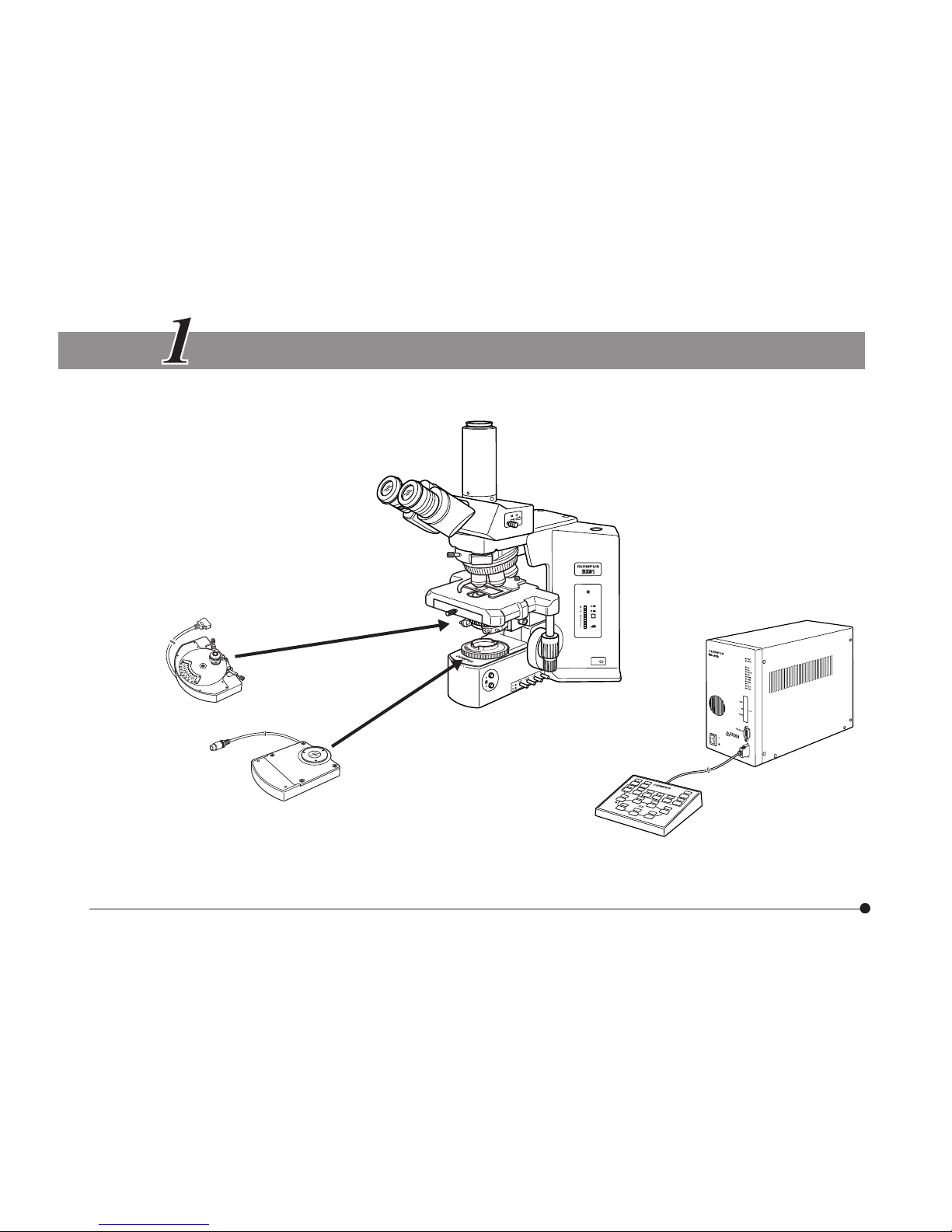
SYSTEM DIAGRAM
}For the connection of connection cables, refer to the instruction manual for the BX-UCB control box.
Motorized Universal Condenser
U-UCD8A
* Necessary in DIC and simple polarized light observation using polarizer (U-FW32PO).
The U-FWCO1.25X low-magnification correction lane is required for observations using the 1.25X objective.
Motorized Transmitted
Light Filter Wheel
U-FWT*
Microscope
BX/BX2 series
Control Box
BX-UCB
Hand Switch
U-HSTR2
U-UCD8A
4
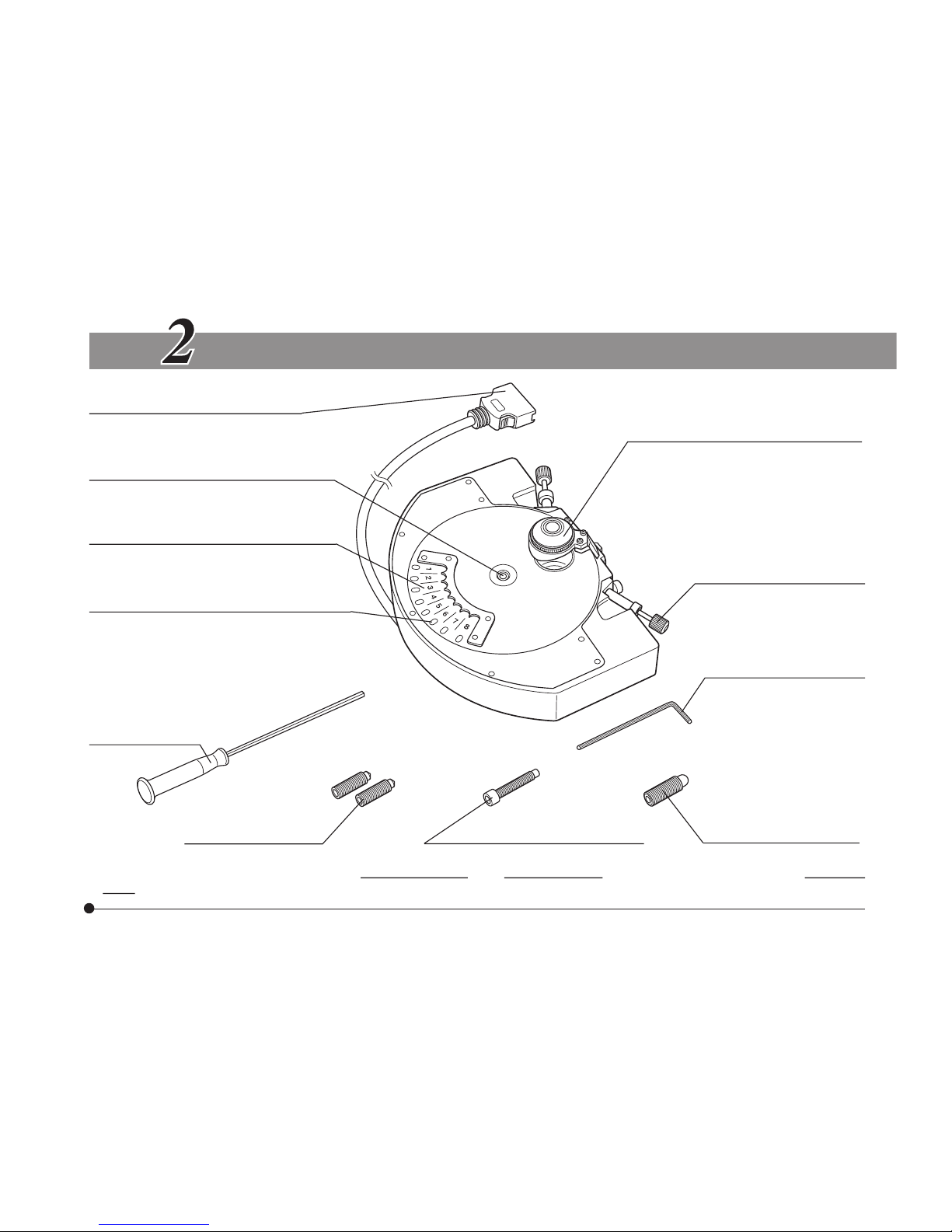
NOMENCLATURE
Connector
To be connected to the BX-UCB.
Turret cover clamping screw (Page 30)
Optical element index plate attaching
positions (Page 31)
x 8 positions.
Optical element index window
“{” shows the optical elements engaged
in the light path.
Allen screwdriver
Condenser centering
screws* (x 2)
Condenser clamping screw* Stage clamping screw*
Top lens (Page 23)
The U-TLD dry type top lens
(provided as standard) may be
exchanged with the U-TLO oil
immersion type top lens (optional).
Optical element centering
knob (Pages 10 & 16)
Allen wrench (Page 33)
Can be attached by
magnetism to the
condenser bottom
surface (be sure to store
here to prevent loss).
* To improve the operability, replace the centering knobs and clamping knob of condenser holder and the clamping
knob of stage with these screws. (Some microscope models adopt screw tightening system.)
5
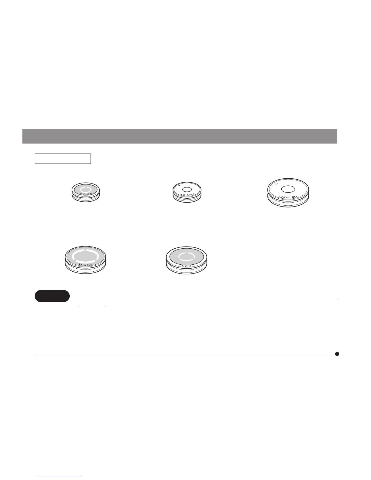
Optical Elements (For the applicable objectives, see pages 25 to 29.)
Phase Contrast Ring (Small)
U-PH1S
U-PH2S
U-PH3S
DIC Prism (Small)
U-DIC10S
U-DP10S
DIC Prism (Large)
Other DIC prism than the
U-DIC10S/U-DP10S.
Darkfield ring
U-DFA
Phase contrast ring (Large)
U-PH3
CAUTION
· The turret has a dummy optical elements attached before factory shipment in order to prevent
loosening of the optical element centering/clamping screw. The dummy optical element can be
removed only when an optical element is to be attached to the turret.
· The dummy optical element (large) can accept a commercially available ND filter (having a frame
diameter of 25
mm). To attach an ND filter, place it in an idle position of the turret, fit the dummy
optical element (large) on it and attach the turret just like an ordinary optical element.
# When a reflective ND filter is used in simple polarized light observation, ghost may be
observed.
+0.3
+0.2

U-UCD8A
6
33
VARIOUS MICROSCOPY PROCEDURES
3-1 Preparation
· If the top lens and optical elements have not been assembled yet, first read Chapter 6, ASSEMBLY” (pages
23 to 35).
· Set the main switch of the BX-UCB control box to “ I ” (ON) to make the microscope ready for observation.
For the operation of the BX-UCB and the U-HSTR2 hand switch, refer to their instruction manuals.
3-2 Brightfield Observation (BF)
Applicable objective power
Power 1.25X 2X 4X 10X 20X 40X 60X 100X
Brightfield (BF) ¦** ¦ ¦ ¦ ¦ ¦ ¦* ¦*
Top lens OUT Top lens IN
* The NA may slightly be insufficient when a dry type top lens is used. However, this does not pose problem
in normal observations.
** Attach the U-FWCO1.25X low-magnification correction lens to the U-FWT filter wheel and engage them in
the light path. The image may be cut by the top lens frame, but this does not cause problem in the TV
observation and photomicrography.
If the objective is used without the correction lens, the light in the peripheral area will be insufficient.

7
}When a transmitted light DIC slider (U-DICT, U-DICTS, etc.) is used in combination, pull out the slider until it
clicks in place to disengage the slider from the light path.
}When a reflected light analyzer (U-AN) is used in combination, pull out the analyzer until it clicks in place to
disengage the analyzer from the light path.
1. Select the BF brightfield observation light path (no optical element engaged).
2. Engage the objective to be used in the light path by rotating the revolving nosepiece.
3. When using a 2X or 4X objective, swing out the condenser’s top lens. Also open the aperture iris diaphragm.
}When the top lens is swung out, the microscope’s field iris diaphragm function as aperture iris diaphragm.
4. Place the specimen on the stage.
5. Move the stage up or down to bring the specimen into focus.
6. Reduce the field iris diaphragm opening until its image circumscribes the field of view.
7. Adjust the aperture iris diaphragm.
}If the slide glass is thicker than 1.2 to 1.4 mm, the image of the field diaphragm may remain fuzzy. When
performing photomicrography, use a side glass with a thickness between 0.9 and 1.2 mm whenever
possible.
U-UCD8A
8
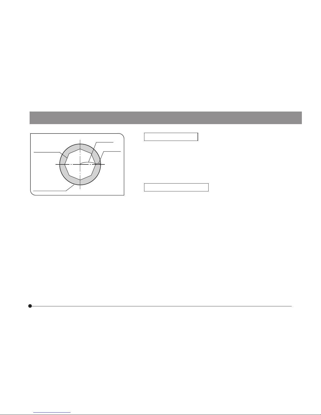
Fig. 1
Field Iris Diaphragm
{The field iris diaphragm controls the size of the illuminated
area. By stopping down the field iris diaphragm, in accordance
with the objective in use, until its image circumscribes the
field of view, stray light can be reduced, which in turn increases
the definition and contrast of the image.
Aperture Iris Diaphragm
{The aperture iris diaphragm controls the numerical aperture
(N.A.) of the illuminator. In order to achieve the optimum objective performance, the opening of the aperture iris diaphragm
should be matched with the N.A. of the objective in use. This
will result in better image contrast and resolution as well as
increased depth of focus.
{As microscopic specimens are usually low in contrast, reduc-
ing the diaphragm opening to 70% or 80% of the objective’s
N.A. will generally provide an image of acceptable quality. To
check the opening, after completing focus adjustment, remove
one of the eyepiece lenses and look into the empty eyepiece
sleeve. As you stop down the aperture iris diaphragm, the iris
diaphragm image can be seen in the objective pupil. (Fig. 1)
Aperture iris
diaphragm
image
Objective pupil
70-80%
30-20%

9
3-3 Phase Contrast Observation (PH)
Applicable objective power
Power 10X 20X 40X 60X 100X
Phase Contrast (PH) ¦* ¦ ¦ ¦ ¦
Top lens IN
* With the super-widefield observation (FN 26.5), flare may be observed in the peripheral areas of the field of
view. However, this does not pose problem in photomicrography.
}When a transmitted light DIC slider (U-DICT, U-DICTS, etc.) is used in combination, pull out the slider until
it clicks in place to disengage the slider from the light path.
}When a reflected light analyzer (U-AN) is used in combination, pull out the analyzer until it clicks in place
to disengage the analyzer from the light path.
1. Select the turret containing the phase contrast ring (U-PH1S, U-PH2S, U-PH3S or U-PH3) matching the
objective in use.
2. Mount the phase contrast objective to be used in the revolving nosepiece and rotate the nosepiece to
engage the objective in the light path.
3. Open the aperture iris diaphragm.
# When the aperture iris diaphragm is stopped down, flare may occur at the center.
4. Place the specimen on the stage and move the stage up or down to bring the specimen in focus.
5. Remove the eyepiece from the eyepiece sleeve and replace with the U-CT30 centering telescope.
 Loading...