

Page 1

UNIVERSAL CONDENSER
This instruction manual is for the Olympus Universal Condenser Model U-UCD8. To ensure the safety, obtain
optimum performance and to familiarize yourself fully with the use of this condenser, we recommend that you
study this manual thoroughly before operating the microscope. Retain this instruction manual in an easily
accessible place near the work desk for future reference.
INSTRUCTIONS
U-UCD8
A X 7 3 5 3
Page 2

Printed on 100% recycled paper with soy ink.
Page 3

U-UCD8
CONTENTS
IMPORTANT — Be sure to read this section for safe use of the equipment. — 1-2
1 NOMENCLATURE 3-5
2 VARIOUS MICROSCOPY PROCEDURES 6-17
2-1 Brightfield Observation (BF) ........................................................................................................................................................................................... 6-8
2-2 Phase Contrast Observation (PH) ......................................................................................................................................................................... 8-9
2-3 Nomarski Differential Interference Contrast Observation (DIC)......................................................................... 10-14
2-4 Darkfield Observation (DF) ........................................................................................................................................................................................ 15-16
2-5 Simple Polarized Light Observation (KPO) ....................................................................................................................................... 16-17
3 TROUBLESHOOTING GUIDE 18-19
4 SPECIFICATIONS 20
5 ASSEMBLY 21-33
5-1 Mounting the Top Lens............................................................................................................................................................................................................ 21
5-2 Mounting the Optical Elements ....................................................................................................................................................................... 22-30
5-3 Mounting the Condenser..................................................................................................................................................................................................... 31
5-4 Centering the Condenser ................................................................................................................................................................................................... 32
i
5-5 Indication Using Number Stickers ......................................................................................................................................................................... 33
Page 4

IMPORTANT
This product is a universal condenser applicable in advanced research applications based on complex
combination of observation methods. By simply exchanging the optical elements, the condenser can be
used in a variety of microscopy under transmitted light, including the brightfield, darkfield, phase contrast,
Nomarski differential interference contrast (DIC) and simplified polarized light observations. The top lens
can be swung in and out to deal with objectives with low magnification (2X) to high magnification (100X).
In addition, brightfield and Nomarski DIC observations using oil immersed objectives are also available
by changing the top lens with an oil immersed top lens.
1 Getting Ready
1. This manual pertains only to the universal condenser unit. Before using this unit together with the microscope (BX40, BX50, BX60, BX41, BX51, BX52, etc.), make sure that you have carefully read and understand
both manuals, and understand how the two units should be used together.
2. This attachment is a precision instrument. Handle it with care and avoid subjecting it to sudden or severe
impact.
3. Make sure that no dirt, fingerprints, etc. are left on the lens surface.
4. Do not force any control beyond its built-in limit (stopper, click, etc.). Avoid using excessive force.
5. Swing out the top lens before attaching or detaching the condenser to or from the microscope.
6. Be sure to center the condenser before use. At maximum decentration of the condenser, the top lens and
stage holder may interfere with each other, making swinging out of the top lens impossible.
7. Remove the condenser from the microscope before attaching or removing the optical elements.
8. Do not clamp the optical element centering screws too tightly.
9. If the optical element centering screws are tightened too much while no optical element is installed, it
may be impossible to return the screws to their original positions.
10. An intermediate tube or sliders may be necessary depending on the method of observation.
11. In brightfield observation, engage the optical elements (small) other than 1, 2 and 3 in the light path. The
field of view may be cut off if optical elements 1, 2 and/or 3 are used.
1
Page 5

2 Maintenance and Storage
1. Clean all glass components by wiping gently with gauze. To remove fingerprints or oil smudges, wipe
with gauze slightly moistened with a mixture of ether (70%) and alcohol (30%).
Since solvents such as ether and alcohol are highly flammable, they must be handled carefully. Be
sure to keep these chemicals away from open flames or potential sources of electrical sparks ——
for example, electrical equipment that is being switched on or off. Also remember to always use
these chemicals only in a well-ventilated room.
2. Do not disassemble any part of the attachment as this could result in malfunction or reduced performance.
3. The optical elements and index plates which are not used should be stored in a case.
U-UCD8
2
Page 6
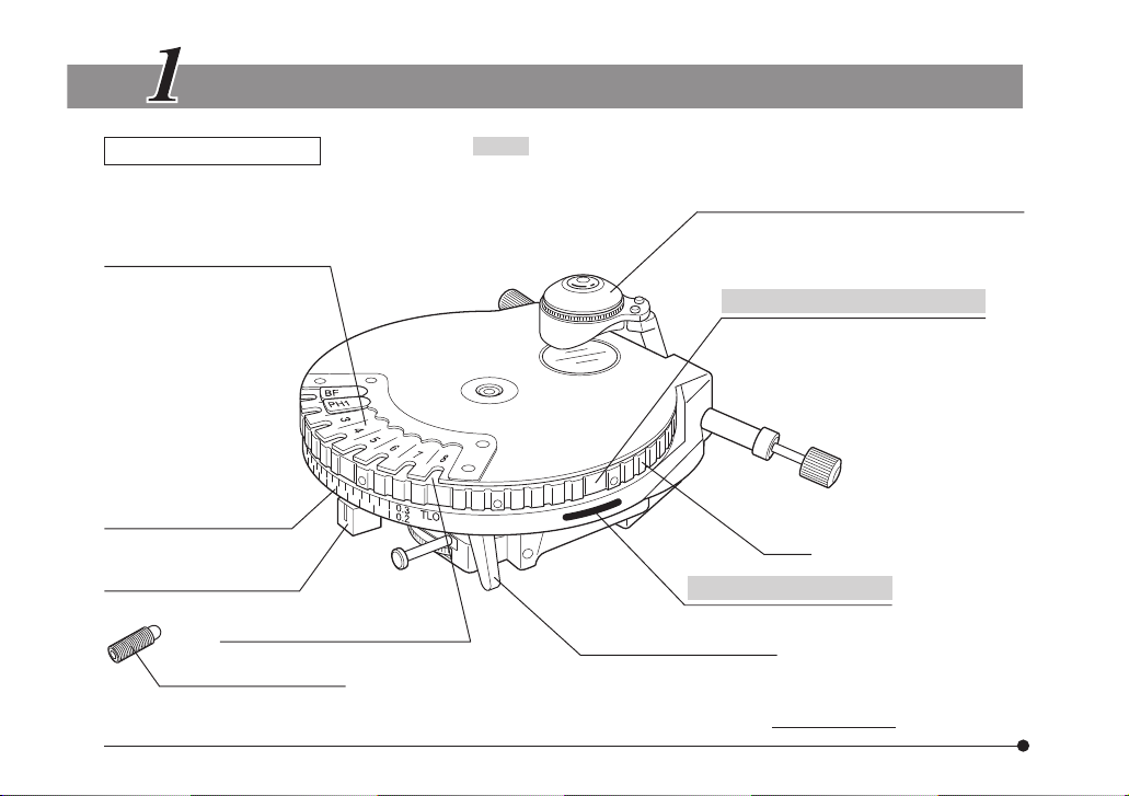
NOMENCLATURE
Universal Condenser
Optical element index plate
mounting position (Page 29)
Aperture iris diaphragm
scale (Page 7)
Aperture iris diaphragm
lever (Page 7)
Stage clamping screw*
* For easier viewing of the optical element index window, replace the stage clamping knob with this screw.
3
(Note) : Used when the U-UCD8 is combined with the IX/IX2
Optical element index window
Series or BX51WI microscope. (Page 33)
Top lens (Page 21)
The standard, dry type top lens (U-TLD) can
be exchanged with the oil immersion type
top lens (U-TLO).
Number sticker attaching groove
Turret
Number index (guideline)
Top lens swing-out lever
Page 7
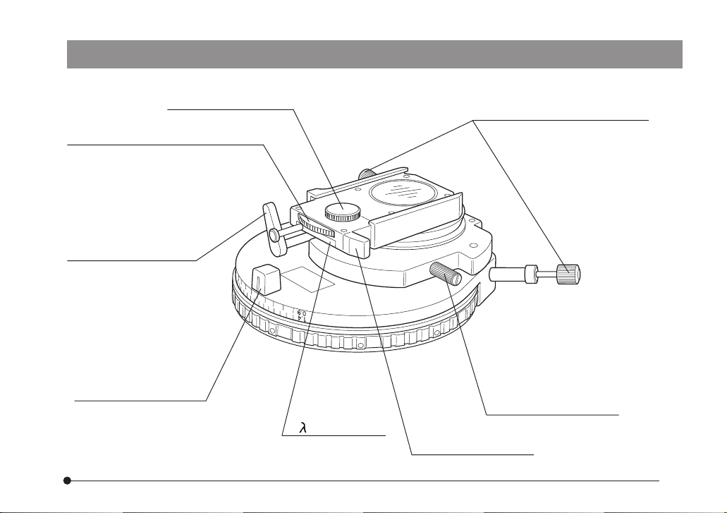
U-UCD8
Polarizer clamping knob
Polarizer rotation knob (Pages 12 & 17)
Top lens swing-out lever
Aperture iris diaphragm
lever (Page 7)
1- plate (Page 14)
Optical element centering screws
(Pages 9 & 15)
Clamping knob
Accommodation position.
Polarizer handling knob
4
Page 8

Optical Elements (For the applicable objectives, see pages 22 - 27.)
Phase Contrast Ring (Small)
U-PH1S
U-PH2S
U-PH3S
5
Darkfield ring
U-DFA
DIC Prism (Small)
U-DIC10S
U-DP10S
Phase contrast ring (Large)
DIC Prism (Large)
Other DIC rings than the
U-DIC10S/U-DP10S.
U-PH3
Number sticker
Indication plate sheet
Page 9

VARIOUS MICROSCOPY PROCEDURES
U-UCD8
}If the top lens and optical elements have not been assembled yet, first read Chapter 5, “ASSEMBLY”
(pages 21 to 30).
2-1 Brightfield Observation (BF)
Applicable objective power
Power 1.25X 2X 4X 10X 20X 40X 60X 100X
Brightfield (BF) – ¦ ¦ ¦ ¦ ¦ ¦* ¦*
Top lens OUT Top lens IN
* The NA may slightly be insufficient when a dry type top lens is used. However, this does not pose
problem in normal observations.
#When a transmitted light DIC slider (U-DICT, U-DICTS, etc.) is used in combination, pull out the
slider until it clicks in place to disengage the slider from the light path.
#When a reflected light analyzer (U-AN) is used in combination, pull out the analyzer until it clicks in
place to disengage the analyzer from the light path.
1. Rotate the turret to select the BF brightfield observation light path (no optical element engaged).
2. Pull out the polarizer handling knob to disengage the polarizer from the light path.
3. Mount the objective to be used in the revolving nosepiece and rotate the nosepiece to swing the objective in place.
4. When using a 2X to 4X objective, swing out the condenser’s top lens. Also open the aperture iris diaphragm.
#When the top lens is swung out, the microscope’s field iris diaphragm function as aperture iris
diaphragm.
5. Place the specimen on the stage.
6. Move the stage up and down to bring the specimen into focus.
6
Page 10

Aperture iris
diaphragm image
Objective pupil
7
7. Reduce the field iris diaphragm opening until its image circumscribes the field of view.
8. Adjust the aperture iris diaphragm.
#If the slide glass is thicker than 1.2 to 1.4 mm, the image of the field diaphragm may remain fuzzy.
When performing photomicrography, use a side glass with a thickness between 0.2 and 1.2 mm
whenever possible.
70-80%
30-20%
Fig. 1
Field Iris Diaphragm
· The field iris diaphragm controls the size of the illuminated
area. By stopping down the field iris diaphragm, in accordance
with the objective in use, until its image circumscribes the
field of view, stray light can be reduced, which in turn increases
the definition and contrast of the image.
Aperture Iris Diaphragm
· The aperture iris diaphragm controls the numerical aperture
(N.A.) of the illuminator. In order to achieve the optimum objective performance, the opening of the aperture iris diaphragm
should be matched with the N.A. of the objective in use. This
will result in better image contrast and resolution as well as
increased depth of focus.
}When using an oil immersion type top lens, read the upper
graduations (marked “TLO”) on the aperture iris diaphragm
scale. When using a dry type top lens, read the lower graduations (marked “TLD”) on the aperture iris diaphragm scale.
Page 11

· As microscopic specimens are usually low in contrast, reducing the diaphragm opening to 70% or 80% of the objective’s
N.A. will generally provide an image of acceptable quality. To
check the opening, after completing focus adjustment, remove
one of the eyepieces and look into the empty eyepiece sleeve.
As you stop down the aperture iris diaphragm, the iris diaphragm image can be seen in the objective pupil. (Fig. 1)
2-2 Phase Contrast Observation (PH)
Applicable objective power
Power 10X 20X 40X 60X 100X
Phase Contrast (PH) ¦* ¦ ¦ ¦ ¦
Top lens (U-TLD) IN (U-TLO cannot be used.)
* With the superwide-field observation (FN 26.5), flare may be observed in the peripheral areas of the field
of view. However, this does not pose problem in photomicrography.
#When a transmitted light DIC slider (U-DICT, U-DICTS, etc.) is used in combination, pull out the
slider until it clicks in place to disengage the slider from the light path.
#When a reflected light analyzer (U-AN) is used in combination, pull out the analyzer until it clicks in
place to disengage the analyzer from the light path.
1. Rotate the turret to engage the phase contrast ring (U-PH1S, U-PH2S, U-PH3S or U-PH3) that matches the
objective in use.
2. Pull out the polarizer handling knob to disengage the polarizer from the light path.
U-UCD8
8
Page 12
9
3. Mount the phase contrast objective to be used in the revolving nosepiece and rotate the nosepiece to
swing in the objective.
4. Open the aperture iris diaphragm.
#When the aperture iris diaphragm is stopped down, flare may occur at the center.
5. Place the specimen on the stage and move the stage up and down to bring the specimen in focus.
6. Remove the eyepiece from the eyepiece sleeve and replace with the U-CT30 centering telescope.
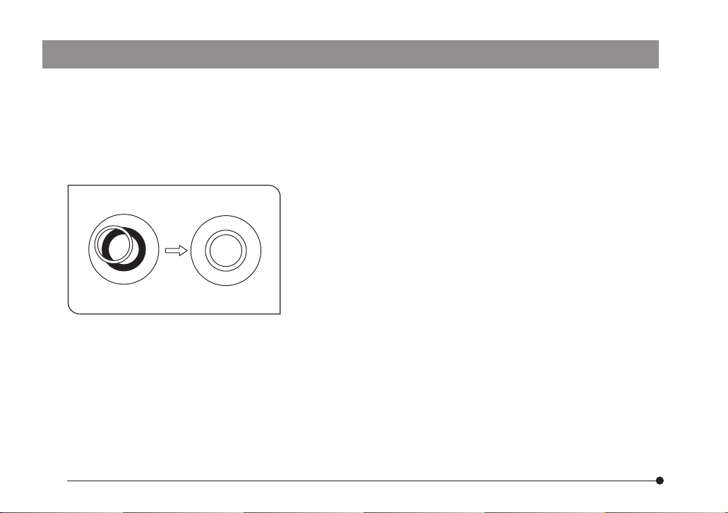
7. Rotate the upper section of the U-CT30 centering telescope
and bring the bright ring (condenser ring slit) and dark ring
(objective phase plate) into focus.
8. Use the optical element centering screw to center the phase
contrast ring so that the bright ring overlaps the dark ring within
the field of view. (Fig. 2)
#If a multiple number of ring slit images appear, select the
brightest ring to overlap with the phase plate.
Fig. 2
9. Repeat steps 7 and 8 for each phase contrast ring.
10. Remove the U-CT30 centering telescope and replace it with
the eyepiece.
11. Widen the field iris diaphragm opening until the diaphragm
image circumscribes the field of view.
}If increased contrast is required, insert the 45IF550 green inter-
ference filter into the filter mount at the base of the microscope frame.
Page 13

2-3 Nomarski Differential Interference Contrast Observation (DIC)
Applicable objective power
Power 10X 20X 40X 60X 100X
Nomarski Differential
Interference Contrast (DIC)
To perform Nomarski DIC observation, the transmitted light DIC slider and an analyzer (U-ANT or U-AN)
are required. Install them by referring to the instruction manual of the DIC slider.
¦¦¦¦¦
Top lens IN
U-UCD8
Installation Using U-DICT
Analyzer for transmitted
light (U-ANT)
Prism control knob
Clamping knob
DIC-compatible revolving nosepiece
(U-D6RE, U-D5BDRE, etc.)
Transmitted light DIC slider
(U-DICT)
10
Page 14

Installation using U-DICTS, U-DICTHC or U-DICTHR
Analyzer
(U-AN)
Clamping knob**
11
To be inserted into the
mount on the vertical
illuminator
Analyzer for transmitted
light* (U-ANT)
To be inserted into the dummy
slider of the U-KPA simplified
polarized light attachment
Prism position switch lever
Pushed in: BFP1
Pulled out: NORMAL
DIC-compatible revolving nosepiece
(U-D6RE, U-D5BDRE, etc.)
Transmitted light DIC slider
(U-DICTS, U-DICTHC or U-DICTHR)
Prism control knob
* When the U-ANT is used in combination with the U-KPA, the field number becomes 22. If superwide-field
observation (field number 26.5) is required without using a vertical illumination, use one of the following
combinations:
@MX-AF’s optional analyzer unit MX-AFDIC + U-AN.
²U-OPA polarized light attachment + U-AN360P polarizer light rotary analyzer.
NOTE When an intermediate attachment is used, align the tube clamping knob on the micro-
scope frame with the clamping knob on the attachment in order to determine the orientation of the analyzer.
** Excessive tightening of the clamping knob hinders operation of the prism position switch lever, so tighten
the knob lightely.
Page 15

U-UCD8
1. Adjust the polarizer in accordance with the following procedure.
@Engage the transmitted light DIC prism slider in the light path and tighten the clamping knob. Then
engage the reflected light analyzer (U-ANT or U-AN) in the light path.
²Rotate the turret to select the BF brightfield observation light path (with no optical element engaged).
³Push in the polarizer handling knob to insert the polarizer into the light path.
Operation using U-DICT and U-ANT
a) Rotate the prism control knob of the transmitted light DIC prism slider clockwise as far as it will go.
b) Rotate the revolving nosepiece to swing in the 10X objective, bring the specimen into approximate focus,
and remove the eyepiece. You can see the pupil of the objective if you look into the inside of the eyepiece
sleeve. (You can see the pupil more easily if you use the U-CT30 centering telescope.)
c) As you rotate the polarizer rotation knob while looking at the
objective pupil, a black fringe may appear at a certain position. The polarizer should be rotated to the position where a
single fringe appears darkest. (Fig. 3)
#If two black fringes appear, rotate the polarizer by approxi-
mately 90
d) Once the position of the polarizer is determined, tighten the
clamping knob to clamp the polarizer.
e) Replace the eyepiece to the original position.
Fig. 3
o
so that only one black fringe is visible.
12
Page 16

When using U-DICT with analyzer other than U-ANT
a) Disengage the DIC slider from the light path.
b) Push in the polarizer handling knob to insert the polarizer into the light path.
c) Rotate the polarizer rotation knob to the position where the field of view is perfectly dark, then tighten the
polarizer clamping knob.
}The perfectly dark (“crossed Nicol”) position is located near the 0
d) Re-engage the DIC slider in the light path.
2. Rotate the turret and engage the DIC prism that matches the objective in use.
3. Rotate the revolving nosepiece to swing in the objective to be used.
}When a transmitted light DIC slider other than the UDICT is used, set the prism position switch lever to
BFP1 or NORMAL according to the objective to be used.
o
position index.
13
Objective with which the BFP1
position should be set
With any objective other than the above, use the NORMAL position.
4. Place the specimen on the stage and move the stage up and down to bring the specimen into focus.
5. Adjust the field iris diaphragm until the diaphragm opening circumscribes the field of view.
6. Stopping down the aperture iris diaphragm somewhat may increase the contrast.
7. Rotate the prism control knob of the DIC slider to adjust the contrast of the background color as dis-
cussed on the next page.
UIS2 Series
UIS Series
UPlanFLN40XO, PlanApoN60XO,
UPlanSApo60XO
UPlanApo40XOI3, UApo40XOI3/340,
UApo40XW3/340, PlanApo60XO3
Page 17

U-UCD8
@Rotate the prism control knob of the DIC slider to obtain the background interference color that can
achieve the maximum contrast according to the specimen under observation.
U-DICT: The background interference color is continuously variable between sensitive gray and
U-DICTS:
U-DICTHC:
U-DICTHR:
· If the background color is black, darkfield-like observation can be performed.
· If the background color is gray, a 3D-like image with maximum contrast with gray sensitive gray can be
obtained.
· If the background color is sensitive magenta, even a minor optical retardation is observed as a color
change.
#Care should be taken to keep the specimen surface clean, as even a small amount of contamina-
tion on the surface may show up due to the exceptionally high sensitivity of the DIC method.
²As DIC exhibits directional sensitivity, the use of rotatable stage is recommended.
#To perform simultaneous reflected light fluorescence and transmitted light DIC observations, refer
to the instruction manual of the Reflected Light Fluorescence Attachment.
#When the PlanApoN60XO, UPlanSApo60XO, PlanApo60XO3 and U-DICTHC are combined (U-
DIC60HC or U-DPO60HC), color irregularities may be noticeable with certain specimens.
sensitive magenta.
The background interference color is continuously variable between
black and dark gray.
}When observing sensitive colors, engage the U-UCDTP530 1-
plate) in the light path.
plate (sensitive color
14
Page 18

15
2-4 Darkfield Observation (DF)
Applicable objective power
Power 10X 20X 40X 60X 100X
Darkfield (DF) ¦* ¦** ¦** ¦** ¦**
Top lens (U-TLD) IN (U-TLO cannot be used.)
* With the superwide-field observation (FN 26.5), flare may be observed in the peripheral areas of the field
of view. However, this does not pose problem in photomicrography.
** Objectives with N.A. of no more than 0.7 can be used. (An objective which is equipped with an iris
diaphragm and which can reduce the N.A. to 0.7 or less can also be used.)
}When a transmitted light DIC slider is used in combination, pull out the slider until it clicks in place to
disengage the slider from the light path.
}When a reflected light analyzer (U-AN) is used in combination, pull out the analyzer until it clicks in place
to disengage the analyzer from the light path.
1. Rotate the turret to select the DFA darkfield observation light path.
2. Pull out the polarizer handling knob to disengage the polarizer from the light path.
3. Mount the objective to be used in the revolving nosepiece and rotate the nosepiece to swing the objective in place.
4. Open the aperture iris diaphragm.
5. Place the specimen on the stage and move the stage up and down to bring the specimen into focus.
6. Remove an eyepiece from the eyepiece sleeve, and look at the objective pupil. Center the darkfield ring
using the optical element centering screw.
7. Insert the eyepiece into the eyepiece sleeve and look at the darkfield image. Repeat centering until the
optimal darkfield effect is obtained.
Page 19

8. Move the condenser up and down until uniform darkfield illumination is attained.
9. Open the field iris diaphragm to the extend that even brightness is attained.
#Keep eyes away from the eyepiece while changing the objective during darkfield observation or
changing from darkfield observation to another observation mode.
If the objective is changed or the turret is rotated to switch the darkfield observation to another observation mode, direct light may enter your eyes.
2-5 Simple Polarized Light Observation (KPO)
Applicable objective power
Power 2X 4X 10X 20X 40X 60X 100X
Simple polarized
light (KPO)
* When the PlanApoN2X, PlanApo2X or UPlanSApo4X, UPlanApo4X objective, or Ph objective for phase
contrast observation is used in polarized light observation, the image contrast may be poorer than the
image observed with other objective magnifications.
}To perform simple polarized light observation, an analyzer (U-ANT or U-AN) is needed. If you have not
installed the fluorescence illuminator yet, install the illuminator by referring to the instruction manual of the
U-ANT transmitted light analyzer.
}When you have already installed the fluorescence illuminator in your system, attach the U-AN reflected
light analyzer by referring to the instruction manual of the reflected fluorescence attachment.
1. Rotate the turret to select the BF brightfield light path (with no optical element engaged).
2. Push in the polarizer handling knob to engage the polarizer into the light path.
3. Mount the objective to be used in the revolving nosepiece, and rotate the nosepiece to swing in the
objective.
Top lens OUT Top lens IN
¦ ¦ ¦ ¦ ¦ ¦
U-UCD8
16
Page 20

17
4. Rotate the polarizer rotation knob to achieve a perfectly black field and then tighten the clamping knob.
}The “crossed Nicol” (perfectly dark) position is located near the 0o position index.
5. Place the specimen on the stage and move the stage up and down to bring the specimen into focus.
6. Adjust the field iris diaphragm opening until it circumscribes the field of view.
7. Stopping down the aperture iris diaphragm may further increase the contrast of the image.
General Precautions in Operation
1. If reflected light fluorescence microscopy in the U-excitation
mode is performed using a 10X or 20X objective with the
condenser engaged, flare may become prominent depending on the specimen condition.
If this occurs and if you do not need transmitted light DIC, either
@
Fig. 4
lower the condenser or use the light shield sheet @ provided
with the reflected light fluorescence attachment. (Fig. 4)
2. When the polarizer rotation knob is set to the 0o position index, the polarizer and analyzer are nearly at the “crossed Nicol”
position. However, since a perfect “crossed Nicol” position can
hardly be achieved due to slight unavoidable positioning error of the intermediate tube, always perform fine adjustment.
3. When the top lens is swung out, the field of view become
obscured if the aperture iris diaphragm is stopped down (when
using a 2X or 4X objective).
4. Due to the large numerical aperture (N.A.), the U-DIC60, UDPO60S, U-DIC100 or U-DP100 DIC prism for 60X and 100X
objectives can also be used for brightfield observation.
Page 21

33
TROUBLESHOOTING GUIDE
Under certain conditions, performance of the unit may be adversely affected by factors other than defects.
If problems occur, please review the following list and take remedial action as needed. If you cannot solve
the problem after checking the entire list, please contact your local Olympus representative for assistance.
Problem Cause Remedy Page
a. Field iris diaphragm image does
not appear when 10X to 100X
objectives are in use.
b. Image glare and resolution is low
under brightfield observation.
c. Ring slit does not align with
phase plate of objective.
d. Darkfield contrast performance is
inadequate.
Slide glass is too thick.
Top lens is swung out. Swing top lens in.
Aperture iris diaphragm s stopped down excessively.
Top lens is swung out.
Incorrect optical element is inserted in light
path.
Incorrect objective is inserted in light path. Engage correct objective into light path.
Top lens is swung out. Swing in top lens.
Aperture iris diaphragm is stopped down. Open aperture iris diaphragm.
Incorrect optical element is inserted in light
path.
Incorrect objective is used. See “Optical Elements and Compatible Ob-
Darkfield ring is not centered correctly. Center darkfield ring correctly.
Use side glasses measuring 1.4 mm or less.
When using immersion type top lens, however,
thickness should be 1.2 mm or less.
Open diaphragm to proper diameter.
Swing top lens into light path when 10X to
100X objectives are in use.
Engage optical element that matches objective in use by rotating turret.
Engage darkfield ring in light path.
jectives”.
U-UCD8
7
3
7
6
22/23
23
15
15
22/23
23
15
18
Page 22

19
Problem Cause Remedy Page
e. Polarizing performance is.
insufficient.
f. No interference color appears dur-
ing Nomarski observation.
g. Interference color appears during
Nomarski observation but color
is uneven.
Polarizer is not inserted in light path. Engage polarizer in light path.
Analyzer is not inserted in light path.
Optical element is engaged.
Aperture iris diaphragm is opened. Either stop down aperture iris diaphragm or
Polarizer is not inserted in light path. Engage polarizer in light path.
Analyzer is not inserted in light path. Engage analyzer in light path.
DIC prism is not inserted in light path. Engage DIC prism by rotating turret.
DIC slider is not inserted in light path. Engage DIC slider in light path.
Polarizer and analyzer are not in “crossed Nicol”
position.
Vertical positioning of condenser is incorrect. Center condenser.
Incorrect optical element is inserted in light
path.
Incorrect objective is in use. See table “Optical Elements and Compatible
1-
plate U-UCDTP530) is inserted in light path. Disengage 1- plate from light path.
Engage analyzer in light path.
Engage empty position by rotating turret.
swing out top lens.
Re-adjust polarizer.
Engage optical element that matches objective in use by rotating turret.
Objectives” and use correct objective.
4
––
––
3
10-14
32
24-27
24-27
14
Page 23

SPECIFICATIONS
44
U-UCD8
Item
Applicable microscope BX40, BX50, BX60, BX41, BX51, BX52, etc.
Applicable microscopy
Type Achromat-Aplanat, swing-out type top lens (Top lens interchangeable)
Applicable slide thickness 0.9 to 1.4 mm 0.9 to 1.2 mm
Working distance 1.5 mm (with 1.2 mm slide) 0.6 mm (with 1.2 mm slide)
Illumination field
Focal length 13.5 mm (top lens in),
Turret 8 positions (Small x 3, Large x 5), optical elements may be attached.
Slider Polarizer (360
Aperture iris diaphragm
Mounting Detachable, circular dovetail, attached with clamping screw.
Dimensions 147.5(W) x 131(D) x 75.5(H) mm (top lens in)
Weight 600 grams
Transmitted light (brightfield, darkfield, phase contrast,
DIC, polarizer light)
3 mm (top lens in),
14 mm (top lens out)
231 mm (top lens out)
2.8 to 21 mm
Dry type top lens (U-TLD) Immersion type top lens (U-TLO)
o
rotatable)
Specifications
Transmitted light (brightfield, DIC)
1.4 (top lens in) when immersed in oil, .02 (top lens out)Numerical Aperture (N.A.) 0.9 (top lens in), 0.2 (top lens out)
1.5 mm (top lens in),
14 mm (top lens out)
8.8 mm (top lens in)
231 mm (top lens out)
20
Page 24

ASSEMBLY
55
5-1 Mounting the Top Lens
@
Fig. 5
}Mount the dry type top lens (U-TLD) or oil immersion type top
lens (U-TLO) depending on your observation requirement.
#When replacing the top lens, make sure not to apply ex-
cessive force to the top lens arm.
Mount the top lens @ by rotating it clockwise. (Fig. 5)
#Do not tighten too firmly. Rotate the top lens until it con-
tacts lightly with the lens holder.
Notes on Oil Immersion Top Lens
#Before engaging or disengaging the top lens, lower the
condenser holder and wipe away oil deposed on the top
lens.
(If you attempt to engage or disengage the top lens without lowering the condenser holder, the slide glass may
impede the operation.)
#If a slide glass thicker than 1.2 mm is used, the field iris
diaphragm image may remain fuzzy.
#Use the oil immersion top lens in combination with an
objective of 20X or higher magnification.
21
Page 25

5-2 Mounting the Optical Elements
U-UCD8
2
3
4
5
6
Fig. 6
1
8
7
1 Optical Element Mounting Positions
1,3: The U-DIC10S or U-DP10S optical element can be mounted.
2: Any of the U-PH1S, U-PH2S and U-PH3S can be mounted.
4,8: The U-DFA and U-PH3 can be mounted. When not in use,
DIC optical elements can be mounted.
5-7: Only DIC optical elements can be mounted because the
centering mechanism is not provided.
(Fig. 6)
22
Page 26

2 Optical Elements and Compatible Objectives
Phase contrast (PH) and darkfield (DF) observations: Using U-TLD top lens
UIS2 Series
Observation Optical Element Applicable Objectives
PlanN10XPh, PlanN20XPh, UPlanFLN10XPh, UPlanFLN20XPh
PlanN40XPh, UPlanFLN40XPh
PlanN100XOPh, UPlanFLN60XOPh, UPlanFLN100XOPh
PH
U-PH1S
U-PH2S
U-PH3S, U-PH3
23
DF
U-DFA
PlanN10X, PlanN20X, PlanN40X, PlanN50XOI, UPlanFLN10X, UPlanFLN20X, UPlanFLN60XOI,
UPlanFLN100XOI, UPlanSApo10X
UIS Series
Observation Optical Element Applicable Objectives
U-PH1S
PH
DF U-DFA
U-PH2S
U-PH3S, U-PH3
Ach10 x Ph, Ach20 x Ph, Plan10 x Ph, Plan20 x Ph, UPlanFl10 x Ph, UPlanFl20 x Ph, UPlanApo10 x Ph
Ach40 x Ph, Plan40 x Ph, UPlanFl40 x Ph, UPlanApo20 x Ph
Ach100 x OPh, Plan100 x OPh, UPlanFl60 x OIPh, UPlanFl100 x OPh, UPlanApo40 x OPh, UPlanApo100 x
OIPh, PlanApo60 x OPh
Ach10 x, Ach20 x, Ach40 x, Plan10 x, Plan20 x, Plan40 x, Plan50 x O
UPlanApo10 x, UPlanFl60 x O
I
3, UPlanFl100 x OI3, UPlanApo20 x, UPlanApo100 x OI3, UApo40 x OI3/340
I
, UPlanFl10 x, UPlanFl20 x, UPlanFl40 x,
Page 27

UIS2 Series
DIC observation (U-DICT/DICTS) (Note) For the U-DICTHC and U-DICTHR, see next page.
DIC Slider U-DICT Shift type U-DICTS
Top Lens U-TLD U-TLO U-TLD U-TLO
UPlanFLN 10X U-DIC10, U-DIC10S --- U-DIC10, U-DIC10S ---
20X U-DIC20 U-ODIC20 U-DIC20 U-ODIC20
40X U-DIC40 U-ODIC40 U-DIC40 U-ODIC40
40XO --- --- U-DIC40 U-ODIC40
60X U-DIC60 U-ODIC60 U-DIC60 U-ODIC60
60XOI
100XO U-DIC100 U-ODIC100 U-DIC100 U-ODIC100
100XOI
UPlanSApo 10X U-DIC10, U-DIC10S --- U-DIC10, U-DIC10S ---
20X U-DIC20 U-ODIC20 U-DIC20 U-ODIC20
40X U-DIC40 U-ODIC40 U-DIC40 U-ODIC40
60XO --- --- U-DIC60 U-ODIC60
60XW U-DIC60 U-ODIC60 U-DIC60 U-ODIC60
100XO U-DIC100 U-ODIC100 U-DIC100 U-ODIC100
PlanApoN 60XO --- --- U-DIC60 U-ODIC60
LUCPlanFLN 20X U-DIC20 U-ODIC20 U-DIC20 U-ODIC20
40X U-DIC40 U-ODIC40 U-DIC40 U-ODIC40
60X U-DIC60 U-ODIC60 U-DIC60 U-ODIC60
: Used with the DIC slider set to the BFP1 position.
U-UCD8
24
Page 28

25
DIC observation (U-DICTHC/DICTHR)
DIC Slider
Top Lens U-TLD U-TLD
UPlanFLN 10X U-DIC10HC U-DIC10HR ---
20X U-DIC20HC U-DIC20HR ---
40X U-DIC40HC U-DIC40HR ---
40XO U-DIC40HC U-DIC40HR ---
60X U-DIC60HC U-DIC60HR U-ODIC60HR
60XO
I
100XO U-DIC100HC U-DIC100HR U-ODIC100HR
I
100XO
UPlanSApo 10X U-DIC10HC U-DIC10HR ---
20X U-DIC20HC U-DIC20HR ---
40X U-DIC40HC U-DIC40HR ---
60XO U-DIC60HC U-DIC60HR U-ODIC60HR
60XW U-DIC60HC U-DIC60HR U-ODIC60HR
100XO U-DIC100HC U-DIC100HR U-ODIC100HR
PlanApoN 60XO U-DIC60HC U-DIC60HR U-ODIC60HR
LUCPlanFLN 20X U-DIC20HC U-DIC20HR ---
40X U-DIC40HC U-DIC40HR ---
60X U-DIC60HC U-DIC60HR U-ODIC60HR
High-contrast type High-resolution type
U-DICTHC U-DICTHR
(for VEC/DIC)
: Used with the DIC slider set to the BFP1 position.
U-TLO
Page 29

U-UCD8
UIS Series
(Note) Usable regardless of the model number (3, 2 or none).
DIC observation (U-DICT/DICTS) (Note) For the U-DICTHC and U-DICTHR, see next page.
DIC Slider U-DICT Shift type U-DICTS
Top Lens U-TLD U-TLO U-TLD U-TLO
UPlanFI 10X U-DP10, U-DP10S --- U-DP10, U-DP10S ---
20X U-DP20 U-ODP20 U-DP20 U-ODP20
40X U-DP40 U-ODP40 U-DP40 U-ODP40
60XO
I
3 U-DPO60S U-ODPO60S U-DPO60S U-ODPO60S
100XO3 U-DP100 U-ODP100 U-DP100 U-ODP100
100XO
I
3
UPlanApo 10X U-DP10, U-DP10S --- U-DP10, U-DP10S ---
PlanApo 60XO3 --- --- U-DPO60S U-ODPO60S
UApo 40X3/340 U-DPA40 --- U-DPA40 ---
10X W3
10XO3
20X U-DPA20 U-ODPA20 U-DPA20 U-ODPA20
20XO3
40X U-DPA40 --- U-DPA40 ---
I
3 --- --- U-DPO40S U-ODPO40S
40XO
60XW3 U-DPO60S U-ODPO60S U-DPO60S U-ODPO60S
60XW3/IR
100XOI3 U-DP100 U-ODP100 U-DP100 U-ODP100
40XW3/340 --- --- U-DPO40S U-ODPO40S
40XOI3/340
: Used with the DIC slider set to the BFP1 position.
26
Page 30

27
DIC observation (U-DICTHC/DICTHR)
DIC Slider
Top Lens U-TLD U-TLD
UPlanFI 10X --- U-DP10HR ---
20X U-DP20HC U-DP20HR ---
40X U-DP40HC U-DP40HR ---
60XO
I
3 U-DPO60HC U-DPO60HR U-ODPO60HR
100XO3 U-DP100HC U-DP100HR U-ODP100HR
I
3
100XO
UPlanApo 10X --- U-DP10HR ---
PlanApo 60XO3 U-DPO60HC U-DPO60HR U-ODPO60HR
10XW3
10X O3
20X --- U-DPA20HR ---
20XO3
40X --- U-DPA40HR ---
60XW3 U-DPO60HC U-DPO60HR U-ODPO60HR
60XW3/IR
I
3 U-DP100HC U-DP100HR U-ODP100HR
100XO
High-contrast type High-resolution type
U-DICTHC U-DICTHR
(for VEC/DIC)
: Used with the DIC slider set to the BFP1 position.
U-TLO
Page 31

U-UCD8
@
²
spring |
Fig. 7
Fig. 8
³
Optical element
Mounting the Phase Contrast Ring
3
or Darkfield Ring
1. Using the Allen screwdriver provided with the microscope,
loosen the turret cover clamping screw @ and remove the
turret cover ².
#When removing the turret cover, care should be taken to
prevent damage to the top lens and the dust protective
glass in the turret cover.
2. Rotate the turret to engage the aperture position you want to
mount the phase contrast or darkfield ring. Then, while pushing in the optical element centering screw ³, loosen it by
turning it counterclockwise.
3. Leave the top lens swung out so it does not impede mounting of the optical elements.
4. Insert the phase contrast ring or darkfield ring in the aperture
of the turret as far as it will go. Slightly depress the spring |
provided inside the turret with the side of ring while inserting.
#Be careful not to push the ring sit plate inside the element
frame.
5. While pushing in the optical element centering screw, tighten
it lightly by turning it clockwise.
#Do not overtighten as this may deform the mount frame of
the optical element.
(Figs. 7 & 8)
(Fig. 8)
28
Page 32

29
}The optical element index plate (Magnet absorption) is pro-
vided with the condenser.
6. Align the optical element mount position No. and the index
ƒ
…
Fig. 9
plate attaching position No. ƒ on the turret cover, then attach
the index plate ….
Page 33

U-UCD8
@
Fig. 10
Fig. 11
4 Mounting the DIC Prism
}The mounting method is variable between the mounting po-
sitions with centering mechanism (1, 3, 4, 8) and those without
centering mechanism (5, 6, 7).
When the mounting position is 1, 3, 4 or 8:
The DIC prism can be mounted in the same way as a phase
contrast ring. However, since a DIC prism is equipped with a
positioning pin, it is required to align the index on the DIC
prism with the positioning index @ on the turret for mounting.
After mounting, attach the index plate.
#Take care not to touch the prism inside the frame during
mounting.
When the mounting position is 5, 6 or 7:
}The DIC prism should be clamped with the clamping knob,
which is accommodated in the left side panel of the condenser, in place of the built-in optical element centering screw.
1. Using the clamping knob ² loosen the clamping screw at
²
the mounting position.
2. Drop in the DIC prism by aligning its positioning pin with the
slot, then tighten the screw using the clamping knob. Then
attach the index plate.
When all of the required optical elements have been mounted,
place the turret cover in the original position.
(Figs. 10 & 11)
30
Page 34

31
5-3 Mounting the Condenser
²
³
@
Fig. 12
(Fig. 12)
Also refer to the instruction manual for the microscope in use.
Attach the condenser to the condenser holder in accordance
with the following procedure.
1. Rotate the coarse adjustment knob @ to raise the stage to a
height where it does not hit the objective. Then rotate the
condenser height adjustment knob ² on the microscope to
lower the condenser holder to the position of the lowest stopper.
2. Loosen the clamping knob ³ on the right side of the condenser holder.
3. Swing out the top lens of the condenser.
4. Insert the condenser in the mounting dovetail of the condenser
holder, and press horizontally until the positioning pin of the
condenser is engaged in the positioning groove of the mounting dovetail.
5. Tighten the clamping knob ³ on the right side of the condenser holder.
6. Raise the condenser holder by rotating the condenser height
adjustment knob ².
Page 35

U-UCD8
5-4 Centering the Condenser
Field iris diaphragm image
Eyepiece field of view
Fig. 13
(Fig. 13)
Also refer to the instruction manual for the microscope in use.
Center the condenser in accordance with the following procedure.
1. Rotate the turret to select the BF brightfield observation light
path (with no optical element engaged).
2. Pull out the polarizer handling knob to disengage the polarizer from the light path.
3. Switch the top lens into the light path.
4. Rotate the aperture iris diaphragm lever clockwise to open
the aperture iris diaphragm.
5. Fully open the field iris diaphragm of the microscope.
6. Place the specimen on the stage, rotate the revolving nosepiece
to swing in the 10X objective, and bring the specimen into focus.
7. Reduce the microscope’s field iris diaphragm opening until
the diaphragm image can be seen.
8. Looking through the eyepiece, raise the condenser almost all
the way up to bring the iris diaphragm image into focus.
9. Gradually opening the field iris diaphragm, bring the reduced
image into the center of the eyepiece field of view, by adjusting the condenser centering knobs of the microscope. (The
reduced polygonal image of the diaphragm should become
inscribed in the circle which indicates the field of view.)
10. After the centering is completed, continue to open the field
diaphragm slightly until its image circumscribes the field of
view.
32
Page 36

33
5-5 Indication Using Number Stickers
#To improve the adhesive strength of the number sticker attaching grooves, remove stain and oil
using the ether-alcohol mixture.
4
5
6
7
8
Fig. 14
Fig. 15
3
2
1
@
1. Fig. 14 shows the relationship between the number sticker
attaching grooves (1 to 8) and the turret.
Attach the number stickers to the designated grooves.
(Note 1) When the condenser is used with an IX/IX2 series
microscope, the condenser is attached upside down.
In consequence, the number stickers should also
be attached upside down.
(Note 2) When the condenser is used with the BX51WI,
attach the number stickers to as low positions as
possible of the turret.
2. Mount the optical elements as described in section 5-2 (pages
22 to 27).
The optical element indication plates should be attached
on the indication plate sheet @. (by means of magnetic
adsorption).
}Check the relationship between the optical element in the
light path and the number indicated by the number index
(guideline).
3. The indication plate sheet has double-side adhesive tape on
the backside. Remove the backing and attach the sheet to an
easily visible location.
(Examples) IX71/51 : Near the front panel.
BX51WI : Near the product name plate.
(Figs. 14 & 15)
Page 37

MEMO
Page 38

MEMO
Page 39

Page 40

Shinjuku Monolith, 3-1, Nishi Shinjuku 2-chome, Shinjuku-ku, Tokyo, Japan
Postfach 10 49 08, 20034, Hamburg, Germany
2 Corporate Center Drive, Melville, NY 11747-3157, U.S.A.
491B River Valley Road, #12-01/04 Valley Point Office Tower, Singapore 248373
2-8 Honduras Street, London EC1Y OTX, United Kingdom.
31 Gilby Road, Mt. Waverley, VIC 3149, Melbourne, Australia.
6100 Blue Lagoon Drive, Suite 390 Miami, FL 33126-2087, U.S.A.
 Loading...