

Page 1
INSTRUCTIONS
U-RFL-T
POWER SUPPLY UNIT
This instruction manual only covers the power supply that is for the Olympus Power Supply Unit
U-RFL-T. To obtain optimum performance and to familiarize yourself fully with the use of this
power supply unit, we recommend that you also study the instruction manual for the microscope
to be used. Retain this instruction manual in an easily accessible place near the work desk for
future reference.
This publication is printed on 100% recycled paper
A X 7 1 1 4
Page 2

Page 3
U-RFL-T
IMPORTANT
This mercury burner power supply unit is only designed for use with Olympus mercury burner light source
attachments. When using this power supply unit, always refer to the instruction manual for the AX, BX, BX2,
IX, etc., reflected light fluorescence module.
SAFETY PRECAUTIONS
1. The applicable lamp housing is a mercury burner configuration Olympus lamp housing (U-ULH, U-ULS100HG,
U-LH100HG, etc.)
2. The high pressure mercury burner (mercury arc lamp) used should be a USH102D burner (mfd. by Ushio Electric) or
HBO103W/2 burner (mfd. by OSRAM).
The ultraviolet rays emitted by the burner are harmful for the eyes and should not be directly looked at with
unprotected eyes. Consequently, the burner should never be turned ON as long as the lamp housing is not
mounted on the microscope.
3. When the burner hour counter of the power supply unit indicates 200 or 300 hours, turn the main switch to “O" (OFF) and
allow the mercury burner to cool for at least 10 minutes before replacing it.
High-pressure gas is sealed within the mercury burner. Thus, if it is continued to be used past its service life
expectancy, the glass tube may deform and may sometimes rupture.
4. When disposing of the mercury burner, always follow national and local laws and guidelines.
5. The power supply unit contains high-voltage components. Never attempt to modify or disassemble the power supply unit.
6. High voltage is applied to ignite the mercury burner. To prevent any hazards, always turn the main switch on the power
supply unit to “O" (OFF), unplug the power cord plug from the mains outlet and disconnect the mercury burner socket
cord plug from the U-RFL-T and wait for at least 10 minutes before replacing the burner.
7. Never switch the main switch to “I" (ON) while the mercury burner socket connection cord plug is not plugged in.
Dangerous high voltage may be output from the output connector.
Safety Symbols
The following symbols are found on the power supply unit. Study the meaning of the symbols, and always use the power
supply unit and the lamp housing in the safest possible manner.
Symbol Explanation
Indicates that the surface becomes hot, and should not be touched with bare
hands.
Indicates that high voltage (upper 1 kV) inside, improper handling could result in an
electric shock to the user.
Before use, carefully read the instruction manual. Improper handling could result in
injury to the user or damage to the equipment.
Indicates that the main switch is ON.
Indicates that the main switch is OFF.
Page 4
Warning Labels
Warning labels are affixed at parts where special precaution is required when handling and using the equipment. Always
heed the warnings.
Power supply unit (U-RFL-T):
Warning label
position
If warning labels become soiled, peel off, etc. contact your local Olympus representative to have them replaced.
100W lamp housing (U-LH100HG):
100W APO lamp housing (U-LH100HGAPO):
Lamp housing (U-ULH):
Socket (U-ULS100HG):
on the side
Top surface
Rear panel
Rear panel
Rear panel
[Warning against high temperature]
[Warning against high voltage]
[Warning against ultraviolet rays]
1 Getting Ready
1. A power supply unit is a precision instrument. Install it on a level surface. Handle it with care and avoid subjecting it to
sudden or severe impact. To prevent obstruction of the air flow, it is important to make sure to leave at least 100 mm
(4 in.) of free space around and above the power supply unit.
2. Do not use the power supply unit where it is subjected to direct sunlight, high temperature and humidity, dust or
vibrations. (For operating environment conditions, refer to and adhere to the conditions specified in Section 4,
SPECIFICATIONS on page 5.)
3. To avoid a potential shock hazard and ensure the electrical safety, be sure to ground the power cord wire. If the power
supply unit is not grounded, Olympus can no longer warrant the electrical safety and performance of the equipment.
4. Always make sure that the main switch is moved to “O" (OFF) before connecting the power cord plug to the wall outlet.
5. For disposal of the mercury burner after use, please observe the applicable ordinance or regulations of the local
government. Contact Olympus in case of doubt.
2 Maintenance and Storage
1. To clean the lenses and other glass components, simply blow dirty away using a commercially available blower and
wipe gently using a piece of cleaning paper (or clean gauze).
If a lens is stained with fingerprints or oil smudges, wipe it gauze slightly moistened with commercially available absolute
alcohol.
Since the absolute alcohol is highly flammable, it must be handled carefully.
Be sure to keep it away from open flames or potential sources of electrical sparks – for example, electrical
equipment that is being switched on or off. Also remember to always use it only in a well-ventilated room.
2. Do not attempt to use organic solvents to clean the non-optical components of the equipment. To clean these, use a
lint-free, soft cloth lightly moistened with a diluted neutral detergent.
3. Do not disassemble any part of the power supply unit as malfunction or damage may occur.
3 Caution
If the equipment is operated in a manner not specified by this manual, the safety of the user may be imperiled. In addition,
the equipment may also be damaged. Always operate the equipment as outlined in this instruction manual.
The following symbols are used to set off text in this instruction manual.
: Indicates that failure to follow the instructions in the warning could result in bodily harm to
the user and/or damage to equipment (including objects in the vicinity of the equipment).
# : Indicates that failure to follow the instructions could result in damage to equipment.
} : Indicates commentary (for ease of operation and maintenance).
Page 5

CONTENTS
U-RFL-T
1
2
3
4
5
NOMENCLATURE 1
ASSEMBLY 1
2-1 Assembly Diagram . . . . . . . . . . . . . . . . . . . . . . . . . . . . . . . . . . . . . . . . . . . . . . . . . . 1
2-2 Mounting the Mercury Burner . . . . . . . . . . . . . . . . . . . . . . . . . . . . . . . . . . . . . . . . 2
2-3 Cable and Cord Connections . . . . . . . . . . . . . . . . . . . . . . . . . . . . . . . . . . . . . . . . 3
PREPARATION FOR OBSERVATION 4
3-1 Igniting the Mercury Burner . . . . . . . . . . . . . . . . . . . . . . . . . . . . . . . . . . . . . . . . . . 4
3-2 Centering the Mercury Burner . . . . . . . . . . . . . . . . . . . . . . . . . . . . . . . . . . . . . . . . 4
SPECIFICATIONS 5
TROUBLESHOOTING GUIDE 6
■■
■ PROPER SELECTION OF THE POWER SUPPLY CORD . . . . . . . . . . . . . . . . . 7
■■
Page 6

1
3
Warning
Indications
Burner
ON LED
Hour
counter
Main
switch
I: ON
O: OFF
NOMENCLATURE
Rating plate
AC receptacle
Output connector
ASSEMBLY
2-1 Assembly Diagram
To illuminator of
microscope frame
(AX, BX, BX2, IX etc.)
Lamp housing U-ULH (Mercury burner configuration)
Collector lens unit
U-UCLHG/XEA,
U-UCLHG/XEB
or IX-UCLHG/XEB
Mercury burner
USH102D
HBO103W/2
Socket
U-ULS100HG
➡
100W lamp housing
U-LH100HG
U-LH100HGAPO
Mercury burner: USH102D
()
HBO103W/2
1
Power Supply Unit U-RFL-T
Page 7
U-RFL-T
2-2 Mounting the Mercury Burner
High voltage is applied to ignite the mercury burner, to prevent any hazards, conform that the main switch on
the power supply unit is switched to "O" (OFF), unplug the lamp housing cord and power cord plug, and wait
at least 10 minutes before proceeding with the replacement.
When using the lamp housing U-ULH
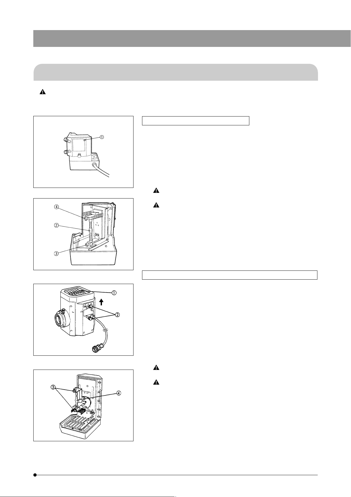
1. Using the Allen screwdriver provided with the microscope frame, loosen
the burner socket clamping screw @. (Fig. 1)
2. Loosen the burner clamping screws ³ and | and remove the transport
post. (For burner replacement, remove the used burner.) (Fig. 2)
3. Insert the + pole of the mercury burner ² into the + terminal and tighten
the + clamping screw ³.
Then loosen the – clamping screw | (marked UP). Insert the – pole of
the burner into the – terminal and tighten the – clamping screw |. (Fig. 2)
Fig. 1
Be sure to use a USH102D burner (mfd. by Ushio Electric) or
HBO103W/2 (mfd. by OSRAM).
Be careful and avoid leaving fingerprints or dirt on the mercury
burner. Attached stain may cause distortion in glass which could
result in a ruptured burner. If the burner is contaminated, clean it
by wiping gently with gauze slightly moistened with absolute
alcohol.
# To prevent possible damage to the burner, the collector lens can
only be installed or removed while the socket and lamp housing
are separated.
Fig. 2
Fig. 3
Fig. 4
When using the 100W lamp housing U-LH100HG/LH100HGAPO
1. Loosen the burner socket clamping screw @ using the Allen screwdriver.
(Fig. 3)
2. While holding the upper part of the lamp housing, pull it vertically to
remove the socket.
# Do not hold the centering knob ². Doing so may use malfunction.
3. Place the socket upside down as shown in Fig. 4.
} Loosen the two burner clamping screws ³ to remove the transport lock
when using the unit for the first time or to remove the old burner when
replacing with a new one. (Fig. 4)
4. Securely attach the + pole of the specified mercury burner | to the upper
mount and the – pole to the lower mount. (Fig. 4)
Be sure to use a USH102D burner (mfd. by Ushio Electric) or
HBO103W/2 (mfd. by OSRAM).
Be careful and avoid leaving fingerprints or dirt on the mercury
burner. Attached stain may cause distortion in glass which could
result in a ruptured burner. If the burner is contaminated, clean it
by wiping gently with gauze slightly moistened with absolute
alcohol.
5. Replace the socket with the burner mounted and tighten the burner
socket clamping screw @.
} While aligning the exterior of the lamp housing with that of the socket, let
down the lamp housing vertically until it fits over the socket.
} For details on mounting the collector lens unit and the lamp housing on
the microscope frame, refer to the instruction manuals for the reflected
light fluorescence modules for the AX, BX, BX2, IX, etc., microscope
frames, respectively.
2
Page 8
3
2-3 Cable and Cord Connections
Cords are vulnerable when bent or twisted. Never subject them
to excessive force.
Make sure that the main switch is set to “O" (OFF) before
connecting cords and cables.
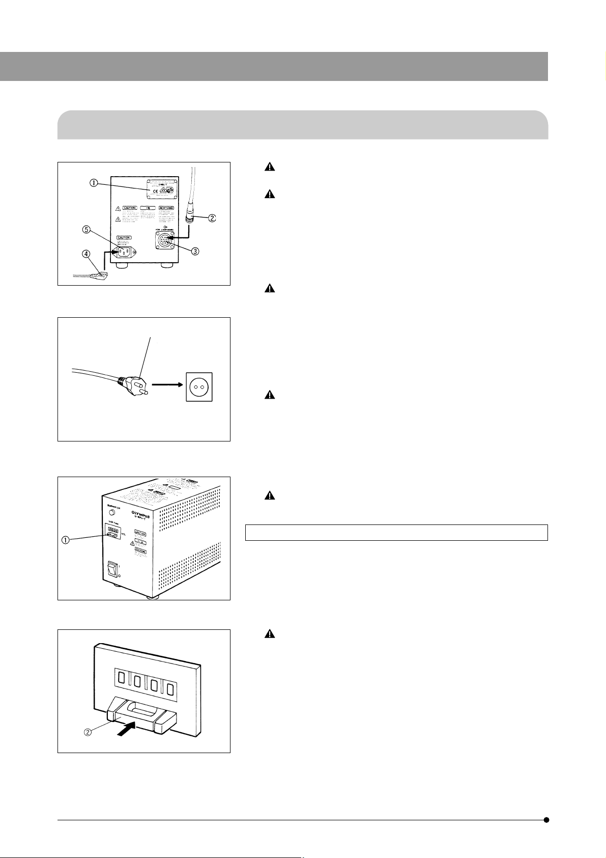
1. Verify that the voltage and frequency of the AC mains outlet match the
requirements indicated on the rating plate @ on the power supply unit.
(Fig. 5)
2. Plug the mercury burner socket connecting cord plug ² firmly into the
output connector ³. (Fig. 5)
Fig. 5
…
Fig. 6
Always use the power cord provided by Olympus. If no power
cord is provided, please select the proper power cord by referring to the section "PROPER SELECTION OF THE POWER SUPPLY
CORD" at the end of this instruction manual. If the proper power
cord is not used, Olympus can no longer warrant the electrical
safety and performance of the equipment.
3. Plug the power cord connector | into the AC receptacle ƒ. (Fig. 5)
4. Plug the power cord plug … into a wall outlet. (Fig. 6)
Connect the power cord correctly and ensure that the ground
terminal of the power supply unit and that of the wall outlet are
properly connected. If the equipment is not grounded, Olympus
can no longer warrant the electrical safety and performance of
the equipment. When installing the power cord, route the power
cord away from the lamp housing. Should the power cord come
in contact with the hot lamp housing, the power cord could melt
and cause electric shock.
Set up cords sufficiently away from the lamp housing. Otherwise
cord covering may melt, posing a risk of electric shock.
3
Fig. 7
Fig. 8
Resetting the Burner Life Time Hour Counter (Figs. 7, 8)
1. To reset the burner life time counter to "000.0", press the center portion ²
of the reset button @ on the power supply unit's front panel.
} The counter shows elapsed time in hours. In order not to impair the safety
of the equipment, replace the burner when the counter indicates "200.0"
hours (USH102D) or “300.0" hours (HBO103W/2). Before replacing the
burner, wait at least 10 minutes after turning the burner off.
The mercury burner contains high-pressured gas and it may
crack if used beyond the specified life time.
Page 9
PREPARATION TO OBSERVATION
3-1 Igniting the Mercury Burner
Never switch the main switch to "I" (ON) while the mercury burner
socket connecting cord plug is not plugged in. Dangerous high
voltage may be output from the output connector.
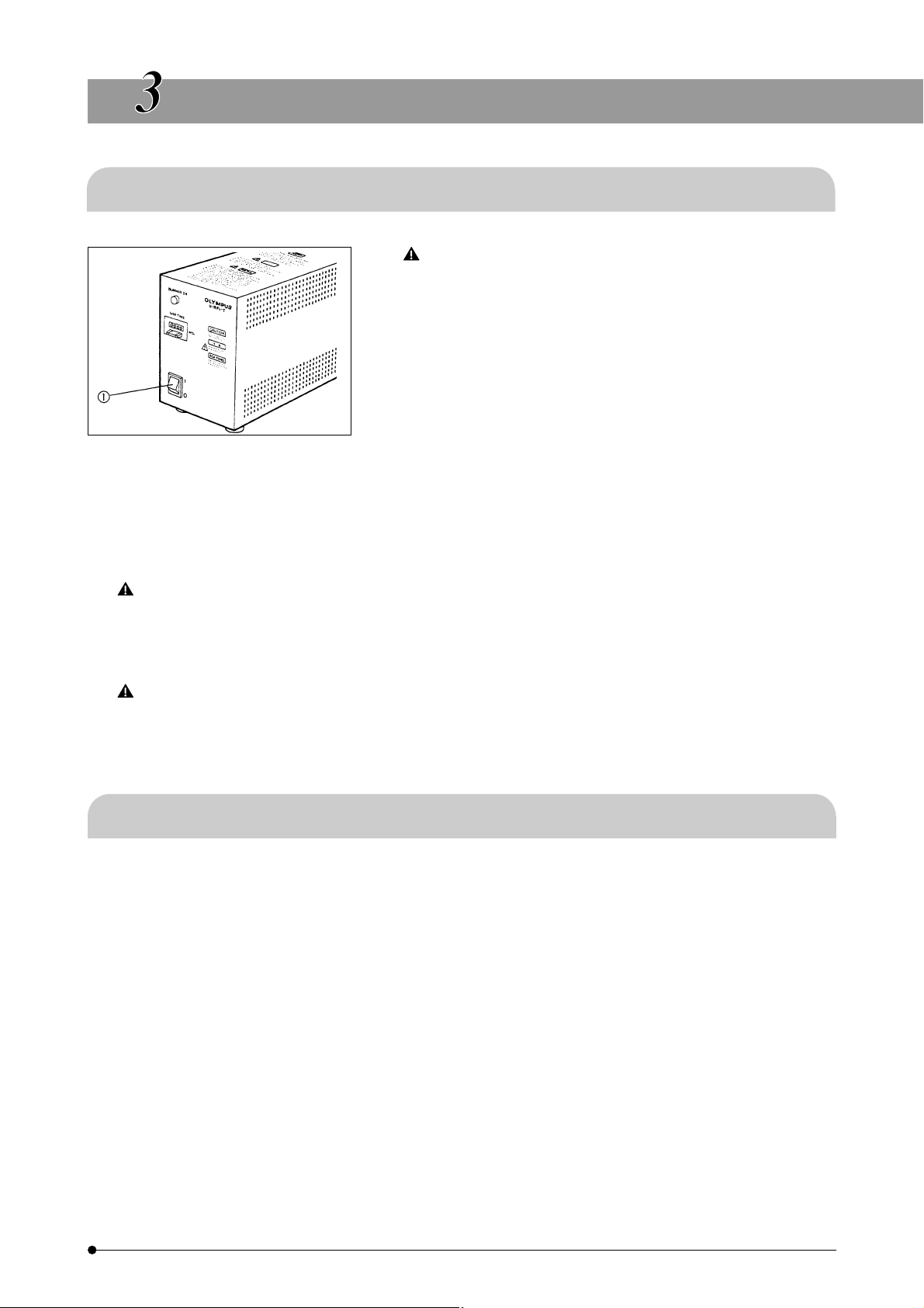
Move the main switch @ on the power supply unit to "I" (ON). Between
5 to 10 minutes are required for the arc to stabilize after the burner is
ignited. (Fig. 9)
# Some mercury burners may not ignite the first time the power is
turned ON. If the burner does not light up in approximately
10 seconds after switching the main switch @ to "I" (ON), switch
the main switch to "O" (OFF) once, then wait 5 to 10 minutes
Fig. 9
before turning it ON again. Repeat as necessary.
# To avoid shortening the life of the burner, do not turn the burner
off within 15 minutes after ignition.
U-RFL-T
# After turning the burner off, it cannot be re-ignited before the mercury vapor cools and condenses to a liquid.
Wait for at least 3 minutes before restarting the burner.
Opening the lamp housing while the burner is ignited is extremely dangerous. Even if the lamp housing is
accidentally opened, interlock mechanism will activate and switch off the power automatically. To restore the
power, switch the main switch of the power supply unit to “O" (OFF) and lock the lamp housing properly.
Then switch the main switch to “I" (ON) again. The lamp housing will become extremely hot during operation.
Always allow it to cool sufficiently before opening.
Ensure that the hour counter is reset to “000.0" after replacement of the burner.
3-2 Centering the Mercury Burner
Center the mercury burner as described in the respective instruction manuals provided with the AX, BX, BX2, IX, etc.
reflected light fluorescence attachments.
4
Page 10
SPECIFICATIONS
■ Power Supply Unit
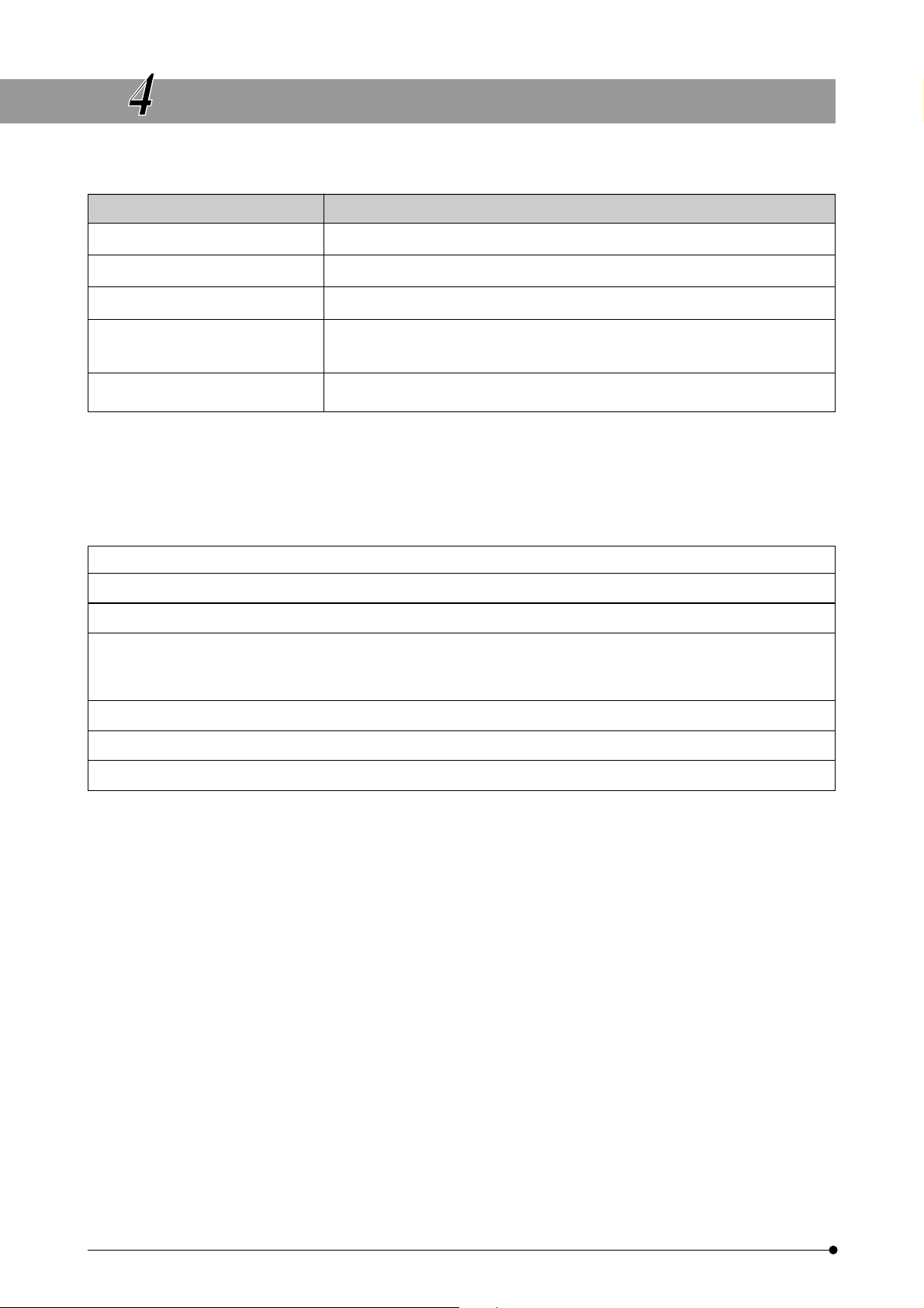
Item Specifications
1. Illumination system Auto-ignition
2. Life meter (counter) Indicates accumulated burner ignition time.
3. Input rating 220–240V $ 1.8A 50/60 Hz (U-RFL-T-200)
4. Dimensions
5. Weight 4.8 kg (10.6 lb.)
■ Operating Environment
{ Indoor use
{ Altitude: Max. 2000 m
{ Ambient temperature: 5° to 40°C ( 41° to 104 °F)
{ Maximum relative humidity 80% for temperatures up to 31°C (88 °F)
decreasing linearly through 70% at 34 °C (93 °F), 60% at 37 °C (99 °F)
to 50% relative humidity at 40 °C (104 °F)
{ Main supply voltage fluctuations not to exceed ±10% of the nominal voltage.
{ Pollution Degree 2 (in accordance with IEC 60664)
{ Installation/Overvoltage Category II (in accordance with IEC 60664)
150 mm (W) X 295 mm (D) X 200 mm (H)
(5.91 in. (W) X 11.6 in. (D) X 7.87 in. (H))
5
Page 11
U-RFL-T
TROUBLESHOOTING GUIDE
Under certain conditions, performance of this unit may be adversely affected by factors other than defects. If problems occur,
please review the following list and take remedial action as appropriate. If you cannot solve the problem after checking the entire
list, please contact your local Olympus representative for assistance.
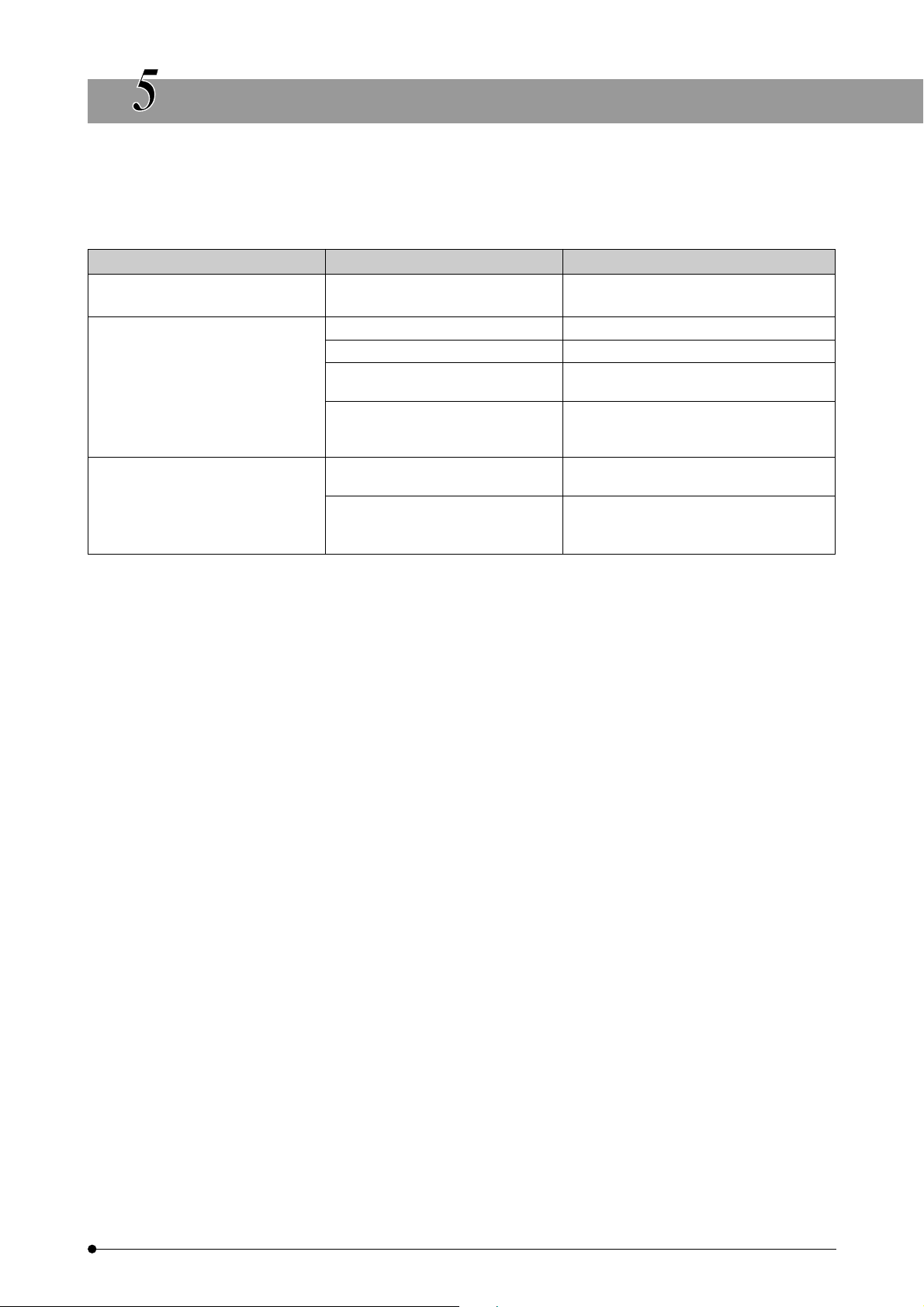
Problem Cause Remedy
a. The main switch LED does not The power cord is not connected. Connect the power cord correctly.
light.
b. Main switch indicator lights, Improperly connected connectors. Connect correctly.
but the mercury burner
does not ignite.
c. The burner flickers or is dark. Insufficient time has elapsed since Wait for 10 minutes after turning on the
The burner is not installed. Install the burner.
The lamp housing interlock Tighten the burner socket clamping screw.
mechanism is activated.
Auto ignition is malfunctioning. Turn the main switch on the power supply
to “O" (OFF). Turn to “I" (ON) again.
(Repeat as necessary.)
the burner was turned on. burner.
The burner life has expired. Replace the mercury burner when the
hour counter reading exceeds 200 hours
(USH102D) or 300 hours (HBO103W/2).
6
Page 12
PROPER SELECTION OF THE POWER SUPPLY CORD
If no power supply cord is provided, please select the proper power supply cord for the equipment by referring to “Specifications” and
“Certified Cord” below:
CAUTION:
In case you use a non-approved power supply cord for Olympus products, Olympus can no longer warrant the
electrical safety of the equipment.
Specifications
Voltage Rating
Current Rating
Temperature Rating
Length
Fittings Configuration
125V AC (for 100-120V AC area) or, 250V AC (for 220-240V AC area)
6A minimum
60°C minimum
3.05 m maximum
Grounding type attachment plug cap. Opposite terminates in molded-on IEC configuration appliance coupling.
Table 1 Certified Cord
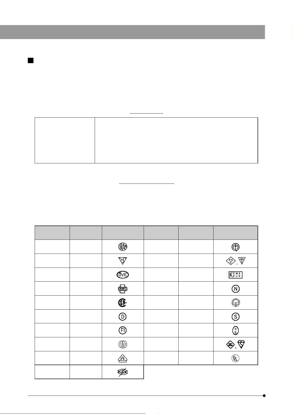
A power supply cord should be certified by one of the agencies listed in Table 1, or comprised of cordage marked with an
agency marking per Table 1 or marked per Table 2. The fittings are to be marked with at least one of agencies listed in
Table 1. In case you are unable to buy locally in your country the power supply cord which is approved by one of the
agencies mentioned in Table 1, please use replacements approved by any other equivalent and authorized agencies in
your country.
Country Agency
Argentina
Australia
IRAM
SAA
Certification
Mark
Country Agency
Italy
Japan
IMQ
JET, JQA, TÜV,
UL-APEX / MITI
Certification
Mark
7
Austria
Belgium
Canada
Denmark
Finland
France
Germany
Ireland
ÖVE
CEBEC
CSA
DEMKO
FEI
UTE
VDE
NSAI
Netherlands
Norway
Spain
Sweden
Switzerland
United
Kingdom
U.S.A.
KEMA
NEMKO
AEE
SEMKO
SEV
ASTA
BSI
UL
Page 13
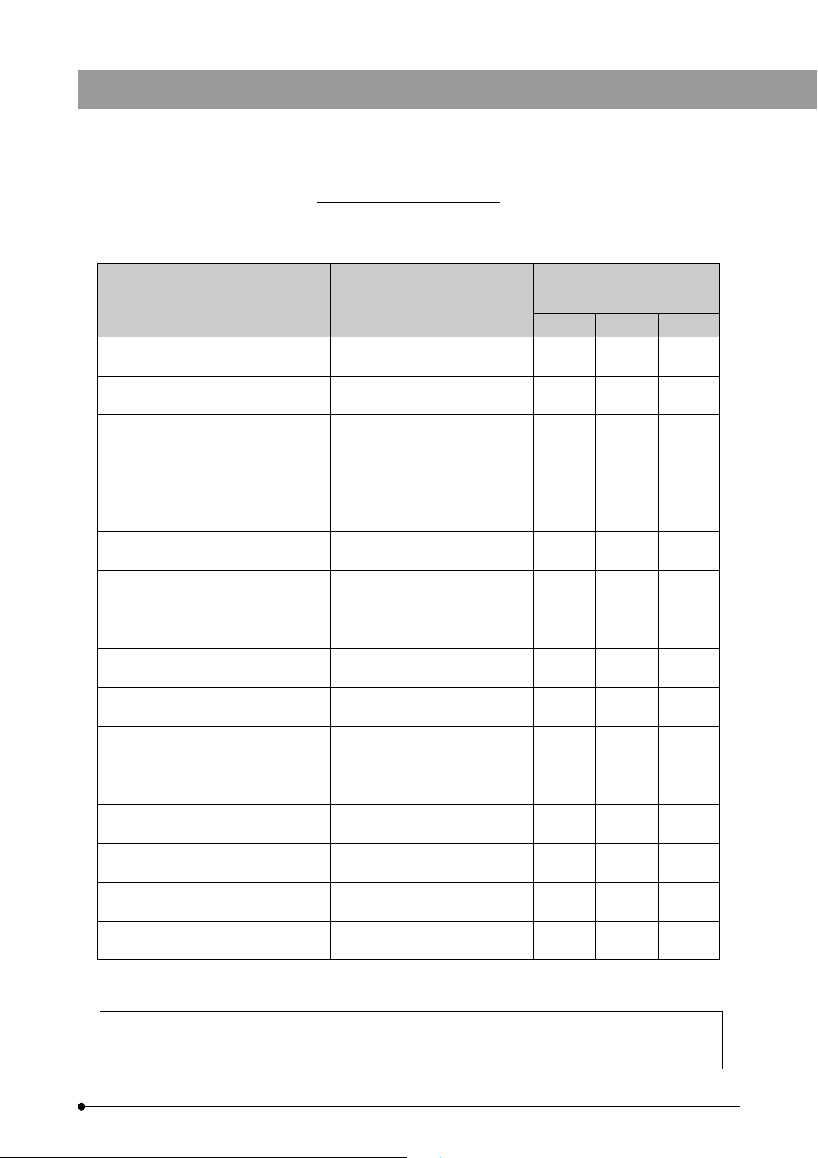
Table 2 HAR Flexible Cord
APPROVAL ORGANIZATIONS AND CORDAGE HARMONIZATION MARKING METHODS
U-RFL-T
Approval Organization
Comite Electrotechnique Belge
(CEBEC)
Verband Deutscher Elektrotechniker
(VDE) e.V. Prüfstelle
Union Technique de l´Electricite
(UTE)
Instituto Italiano del Marchio di
Qualita (IMQ)
British Approvals Service for Electric
Cables (BASEC)
N.V. KEMA
SEMKO AB Svenska Elektriska
Materielkontrollanstalter
Österreichischer Verband für
Elektrotechnik (ÖVE)
Danmarks Elektriske Materialkontroll
(DEMKO)
Printed or Embossed Harmonization Marking (May be located on
jacket or insulation of internal wiring)
CEBEC <HAR>
<VDE> <HAR>
USE <HAR>
IEMMEQU <HAR>
BASEC <HAR>
KEMA-KEUR <HAR>
SEMKO <HAR>
<ÖVE> <HAR>
<DEMKO> <HAR>
Alternative Marking Utilizing
Black-Red-Yellow Thread (Length
of color section in mm)
Black Red Yellow
10 30 10
30 10 10
30 10 30
10 30 50
10 10 30
10 30 30
10 10 50
30 10 50
30 10 30
National Standards Authority of Ireland
(NSAI)
Norges Elektriske Materiellkontroll
(NEMKO)
Asociacion Electrotecnica Y
Electronica Espanola (AEE)
Hellenic Organization for
Standardization (ELOT)
Instituto Portages da Qualidade
(IPQ)
Schweizerischer Elektro
Technischer Verein (SEV)
Elektriska Inspektoratet
Underwriters Laboratories Inc. (UL) SV, SVT, SJ or SJT, 3 X 18AWG
Canadian Standards Association (CSA) SV, SVT, SJ or SJT, 3 X 18AWG
This device complies with the requirements of both directive 89/336/EEC concerning electromagnetic compatibility
and directive 73/23/EEC concerning low voltage. The CE marking indicates compliance with the above directives.
<NSAI> <HAR>
NEMKO <HAR>
<UNED> <HAR>
ELOT <HAR>
np <HAR>
SEV <HAR>
SETI <HAR>
30 30 50
10 10 70
30 10 70
30 30 70
10 10 90
10 30 90
10 30 90
8
Page 14

MEMO
Page 15

Page 16

Shinjuku Monolith, 3-1, Nishi Shinjuku 2-chome, Shinjuku-ku, Tokyo, Japan
Postfach 10 49 08, 20034 Hamburg, Germany
2 Corporate Center Drive, Melville, NY 11747-3157, U.S.A.
491B River Valley Road, #12-01/04 Valley Point Office Tower, Singapore 248373
2-8 Honduras Street, London EC1Y OTX, United Kingdom.
31 Gilby Road, Mt. Waverley, VIC 3149, Melbourne, Australia.
6100 Blue Lagoon Drive, Suite 390 Miami, FL 33126-2087, U.S.A.
Printed in Japan 2006 07 M 007-²
 Loading...