

Olympus U-LH50HG, CKX41, CKX-RFA, CKX-NU, U-RFLT50 Instructions Manual

INSTRUCTIONS
REFLECTED
FLUORESCENCE
SYSTEM
FOR CKX41
A X 7 3 8 9
This instruction manual is for the Olympus Reflected Fluorescence System for
use with the CKX41 culture microscope. To ensure the safety, obtain optimum
performance and to familiarize yourself fully with the use of this system, we
recommend that you study this manual thoroughly before operating the system.
Retain this instruction manual in an easily accessible place near the work desk
for future reference.
Modules described in this manual
CKX-RFA
U-LH50HG
U-RFLT50
CKX-NU
This publication is printed on 100% recycled paper


CONTENTS
To le t t he ref le ct ed fl uo re sc en ce sy st e m m an if es t i ts f ul l p er fo rm anc e, i t i s c r it ic al th at y ou
assemble and adjust the system properly. If you want to assemble the system yourself, read
Chapter 7, “ASSEMBLY” (pages 21 to 28) first.
IMPORTANT
- Be sure to read this first for safe use of the equipment. -
1 NOMENCLATURE
1
General Precautions for Observation
4 Turning O n t h e Mercu ry B urner
6 Centering the Field Iris Diaphragm
3
Applicable Fluorescence Objectives
5 Centering the Mercury Burner
1-3
9-17
21-28
20
5 TROUBLESHOOTING GUIDE 18,19
7 Switching the Filter Slider
2 CONTROLS OF EACH MODULE
3
SUMMARY OF REFLECTED FLUORESCENCE OBSERVATION PROCEDURE
4 USING THE CONTROLS
4
5,6
7, 8
6 SPECIFICATIONS
7 ASSEMBLY
8 U-EXCITATION FILTER SET CKX-NU (OPTIONAL)
29
REFLECTED FLUORESCENCE SYSTEM FOR CKX41
2
Selecting the Reflected Light Fluorescent Mirror
PROPER SELECTION OF THE POWER SUPPLY CORD................................................... 30,31
1
IMPORTANT
The reflected fluorescence system is designed to be mounted on the CKX41 culture microscope
to enable the transmitted light observation and B/G-excited (U-excitation optionally available)
fluorescence observation by switching them using a slider.
SAFETY PRECAUTIONS
1 . Make sure that the main switch of the power supply unit is set to “ ” (OFF) before connecting the
power cord to the AC outlet.
2 . The power supply unit contains high-voltage components. Never attempt to disassembly the unit, or
you may run the risk of electric shock.
3 . Always be sure to ground (earth) the equipment. Otherwise, Olympus will no longer warrant the
electrical safety of the equipment.
4 . The reflected fluorescence system should be installed on a flat surface so that the ventilation opening
on the bottom panel is not blocked.
Do not install the system on a surface which is soft or which may collapse under the weight of the
microscope, for the subsequent blockage of the bottom panel ventilation opening could create a fire
hazard.
5 . The high-pressure mercury burner used should be the HBO50W/AC (OSRAM) or CS50W4 (PHILIPS).
6 . Before opening the lamp housing for replacement of the burner or any other internal part, set the
mains witch to “ ” (OFF), unplug the lamp housing connecting cord from the outlet connector on the
power supply unit, and wait 10 minutes or more until the lamp housing cools down.
7 . Do not open the lamp housing while it is turned on or for at least 10 minutes after it has been turned
off. Lamp housing parts are extremely hot and cause burns if touched (see page 13).
8 . Do not remove the lamp housing while the burner is lit.
A ls o , d o n o t t u rn th e b u rn e r o n w h i le th e l a mp ho u si n g i s re m o v ed .
9 . Do not install the lamp housing upside down or at an angle.
The lamp housing surface becomes very hot during operation, so ensure that there is ample free
space around the lamp housing, especially above and below.
10 . If the microscope power cord comes in contact with the lamp housing or its surroundings, the cord
may melt and subsequently cause electric shock. Be sure to position the power cord at a safe
distance from the lamp housing.
11 . A u s e d m e r c u r y b u r n e r s h o u l d b e d i s p o s e d o f i n c o m p l i a n c e w i t h t h e o r d i na n c e s o r r e g u l at i o n s o f
your national or local government.
12 . To re pl ac e th e li th iu m ba tt er y (f or t he h ou r c ou nt er ) bu il t in to t he p ow er s up pl y un it , co ns ul t Ol ym pu s.
As the power supply unit incorporates a lithium battery, it should be disposed of in the same way as a
used mercury burner, i.e., in compliance with the ordinances or regulations of your national or local
government.
13 . B ef or e p la ce me nt of t he d us t c ov er fo r pr ote ct io n a fte r o pe ra tio n, wa it un t il th e l am p ho us in g c ool s
down sufficiently and unplug the power cord.
2
REFLECTED FLUORESCENCE SYSTEM FOR CKX41
Safety Symbols
I
\
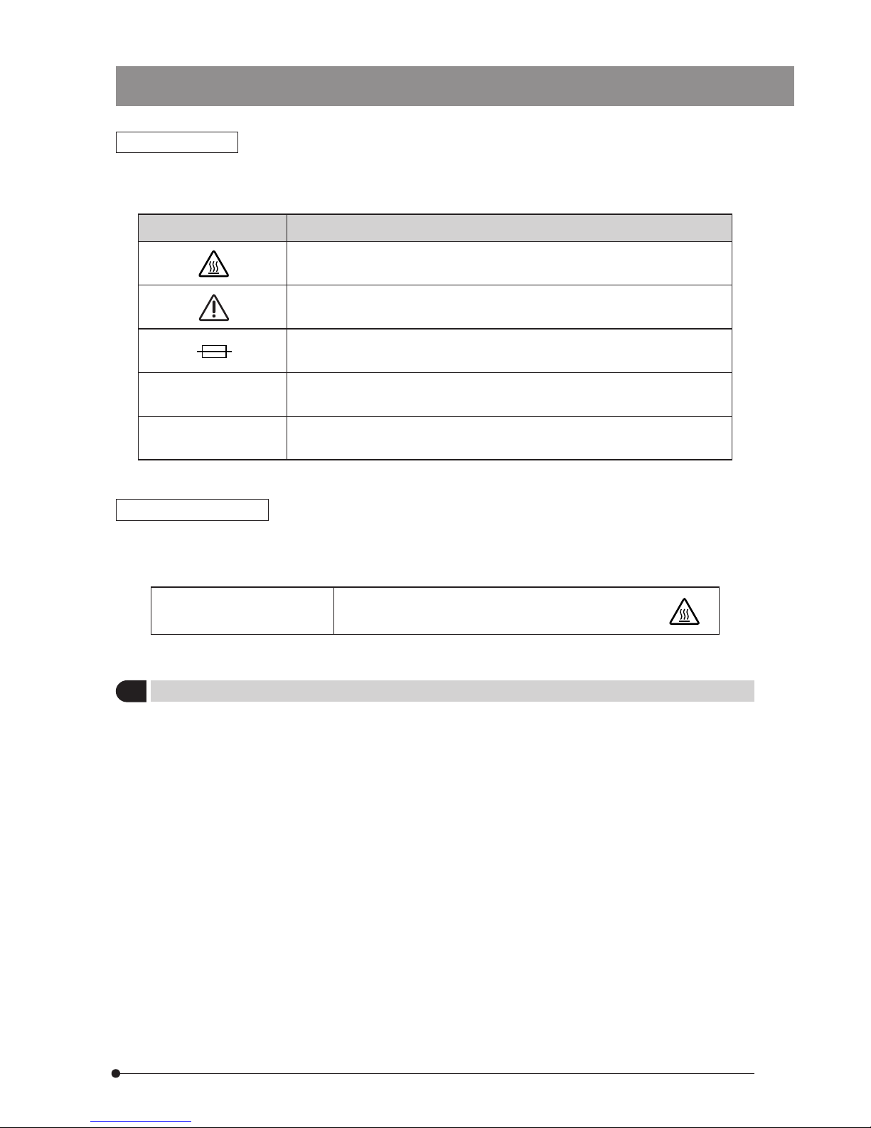
The following symbols are found on the system. Study the meaning of the symbols and always use the
equipment in the safest possible manner.
Symbol Explanation
Indicates that the surface becomes hot, and should not be touched with
bare hands.
Before use, carefully read the instruction manual. Improper use could result
in personal injury to the user and/or damage to the equipment.
Indicates a potential fire hazard; when replacing fuses, be sure that the
replacement fuses are of the specified rating.
Indicates that the main switch is ON.
Indicates that the main switch is OFF.
Warning Indications
Warning indications are placed at parts where special precaution is required when handling and using
the system. Always heed the warnings.
Warning indication position
1
Getting Ready
Lamp housing
U-LH50HG
[Warning against high temperature]
1. Th e s yste m is comp os ed of pr ec is io n i ns tr um en ts . H an dl e it wi th c ar e an d avo id sub je ct in g it to s ud den
or severe impact.
2. Do not use the system where it is subjected to direct sunlight, high temperature and humidity, dust or
vibrations. (For the operating conditions, see chapter 6, “SPECIFICATIONS”.)
3. Make certain that the burner is installed correctly and that all cords are correctly connected.
4. The stopper mechanisms provided for the functions indicate the limits of motion. To prevent damage,
do not apply excessive force to these limiting mechanisms.
5. Flare may be observed in fluorescence observation using cooled CCD. This flare can be reduced by
inserting a filter, which is available on custom order, in the fluorescence illumination tube. (Please
contact Olympus.)

3
2
Maintenance and Storage
1. Be careful to avoid leaving dirt or fingerprints on the lenses, filters and high-pressure mercury burner,
for contamination of these parts may cast the shadow of a foreign object in the field of view or
compromises the burner performance.
If a glass component is contaminated, clean it by wiping gently with gauze. To remove fingerprints or oil
smudges, wipe with gauze slightly moistened with a mixture of ether (70%) and alcohol (30%).
Since solvents such as ether and alcohol are highly flammable, they must be handled carefully.
Be sure to keep these chemicals away from open flames or potential sources of electrical
sparks —— for example, electrical equipment that is being switched on or off. Also remember
to always use these chemicals only in a well-ventilated room.
2. The mercury burner has an average service life of 100 hours. When the hour counter on the power
supply unit indicates 100 hours, replace the burner with a new one (see page 26).
Using a burner after its service life expires could lead to the burner exploding, though this occurs very
rarely.
3. The surfaces of the dichroic mirror and excitation/barrier filters are very delicate. When it becomes
necessary to clean it, please contact Olympus.
4. Do not disassemble any part of the system as this could result in malfunction or reduced performance.
If the system is used in a manner not specified by this manual, the safety of the user may be imperiled.
In addition, the equipment may also be damaged. Always use the equipment as outlined in this instruction manual.
3 Caution
The following symbols are used to set off text in this instruction manual.
: Indicates that failure to follow the instructions in the warning could result in bodily
harm to the user and/or damage to equipment (including objects in the vicinity of the
equipment).
# : Indicates that failure to follow the instructions could result in damage to equipment.
}:Indicates commentary (for ease of operation and maintenance).
4
REFLECTED FLUORESCENCE SYSTEM FOR CKX41
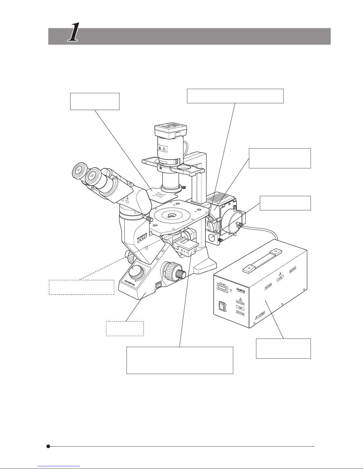
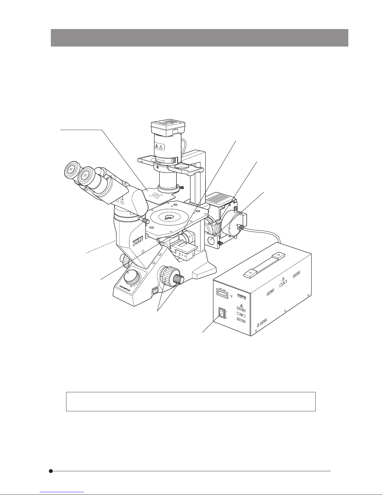
NOMENCLATURE
Excitation light
protective shield
Reflected Fluorescence Illuminator
CKX-RFA
Lamp Housing for
50 W Mercury Burner
U-LH50HG
*
ND Filter
32ND6/12/25/50
Fluorescent objectives
(See pages 11 & 12.)
Microscope
CKX41
Reflected fluorescent mirror slider
· B-excitation
· G-excitation
· Option: U-excitation filter set CKX-NU
Power Supply Unit
· U-RFLT50-100
· U-RFLT50-200
* A metal halide lamp can be used instead of the 50 W mercury burner (except in U-excitation). (Lamp
housing: U-LH50MH. Power supply unit: U-PS50MH)
* The 100 W mercury burner cannot be used.
*
5
CONTROLS OF EACH MODULE
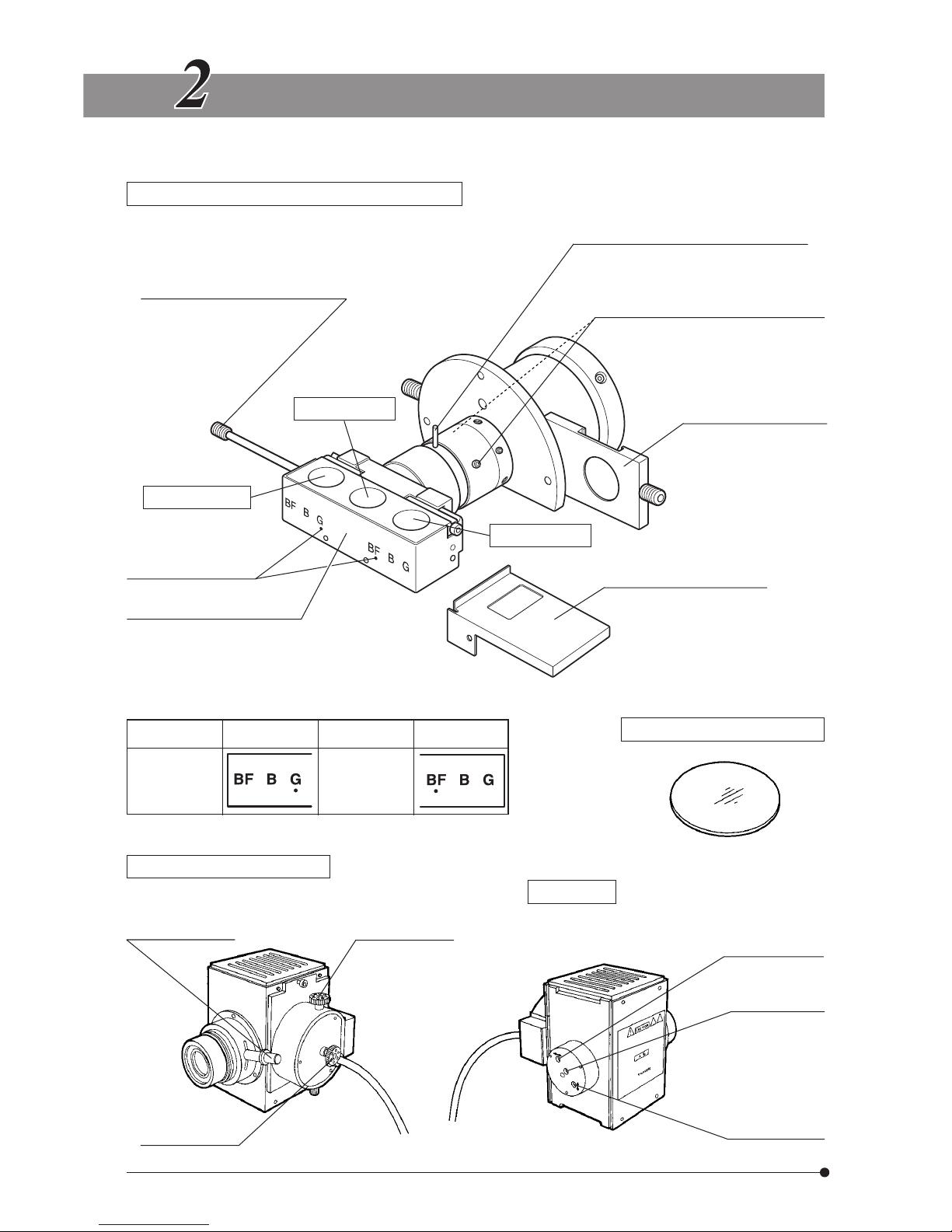
Reflected Fluorescence Illuminator CKX-RFA
Fluorescent mirror switching lever
This can also be attached
on the opposite side.
BF light path
B-excitation
G-excitation
Light path indicators*
Fluorescent mirror slider
BF/B-excitation/G-excitation.
Field iris diaphragm lever
To o p en : T ur n cl o ck wi se .
To s t op do wn : Tu rn c ou nt erc lo ckw is e.
Field iris diaphragm centering screws
Turn using the provided Allen wrench.
Filter slider
Shutter/Open position/
Filter pocket
Dust covers (x 2)
With two clamping knobs.
* View of light path indicators from the front side of microscope
ND Filter 32ND6/12/25/50
Light Path G-excitation B-excitation Brightfield
View No indication
Lamp Housing U-LH50HG
Collector
focusing knob
Burner left/right
centering knob
Burner up/down
centering knob
Rear view
Mirror left/right
centering screw
Mirror focusing
screw
Mirror up/down
centering screw
6
REFLECTED FLUORESCENCE SYSTEM FOR CKX41
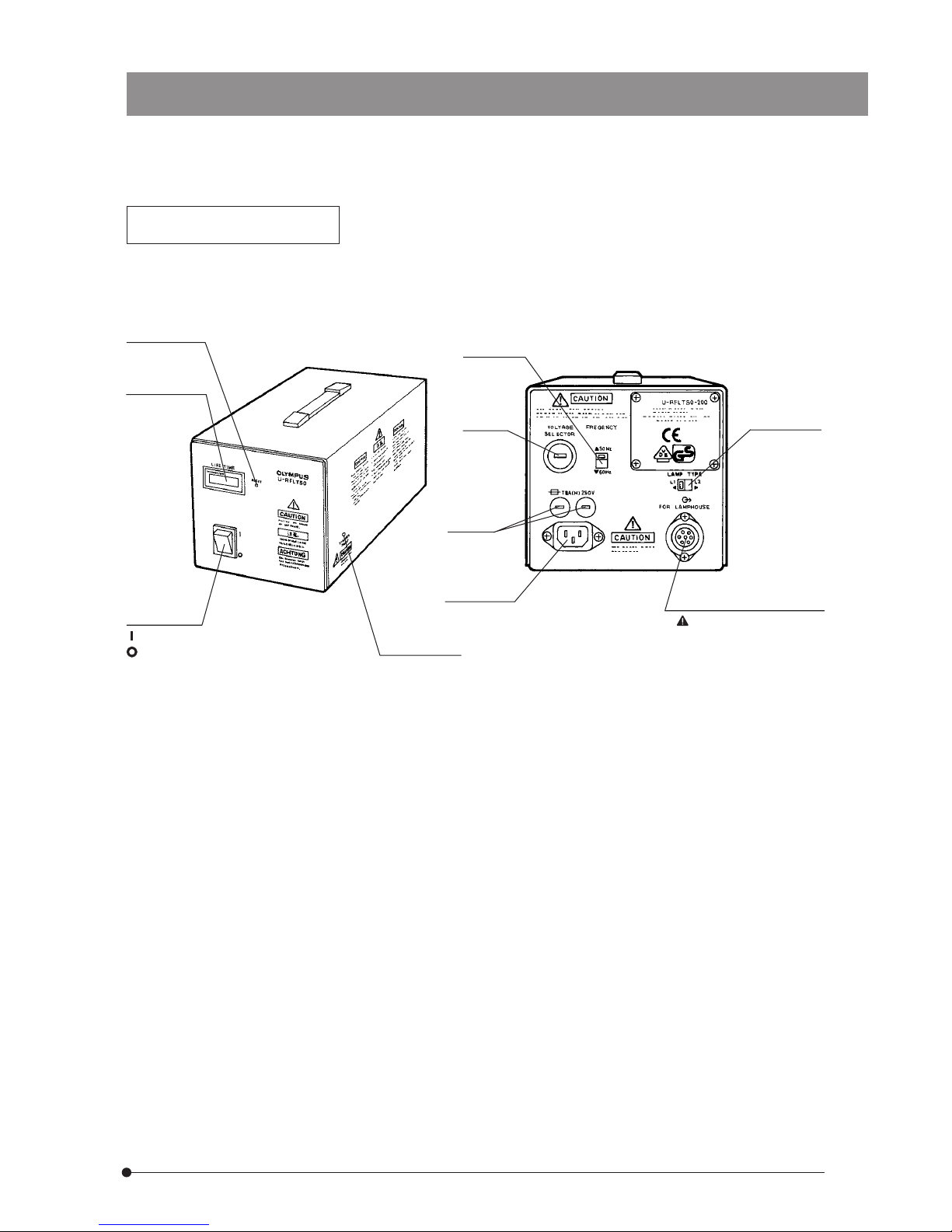
Power Supply Unit for 50 W
Mercury Burner U-RFLT50
#The depth dimensions of the 100 V and 200 V models differ from each other.
Reset button
Hour counter
Main switch
: ON
:
OFF
Starter reset
switch
Frequency
switch
Voltage
switch
Burner type
switch
Fuse
holders
Power cord
connector
Lamp housing
connector
For exclusive use with
the U-LH50HG.
7
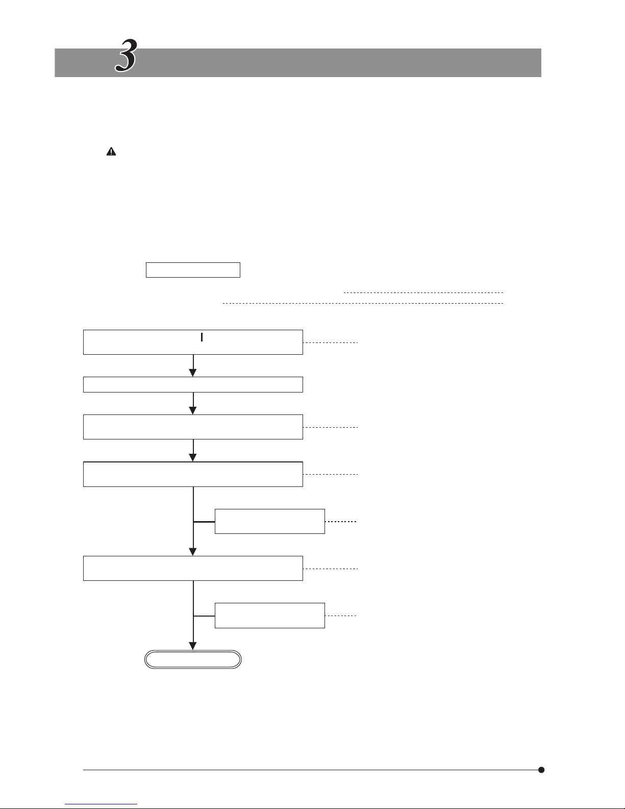
SUMMARY OF REFLECTED FLUORESCENCE OBSERVAT ION PRO CE DUR E
}If you view excitation light during observation, the light may be slightly glaring except when it is seen
through the excitation light protective shield. However, as the lamp housing incorporates a UV cut filter,
the excitation light is not hazardous even if it enters your eye. However, it is still recommended to view
the excitation light through the excitation light protective shield whenever possible.
When U-excitation is used, always be sure to view it through the excitation light protective shield.
}When it is required to interrupt observation for a short period, use the shutter (in 4 Filter slider).
}When searching for the observation target position on the specimen, it is recommended to set the
CKX41 for transmitted brightfield observation (possible by stopping down the aperture iris diaphragm) or
transmitted phase contrast observation to facilitate it. After locating the observation target position, turn
off the transmitted light illumination.
(Controls Used) (Page)
Preparation
· Mount the objective suitable for the microscopy to be used.
· Centering the mercury burner.
(P. 11,12)
(P. 14, 15)
Set the main switch to “ ” (ON) and wait until
the arc stabilizes (5 to 10 min.).
1 Main switch (P. 13)
Place the specimen on the stage.
Engage the fluorescent mirror matching the
specimen in the light path.
2 Fluorescent mirror switching lever (P. 5, 10)
Engage the objective in the light path, open the
shutter and bring the specimen into focus.
3 Revolving nosepiece
4 Filter slider (Shutter)
5 Coarse/fine adjustment knobs
(P. 17)
Engage the ND filter in
light path as required.
4 Filter slider (ND filter) (P. 17)
Adjust the brightness so that the entire field of
view is uniformly bright.
6 Collector focusing knob (P. 15)
Adjust the aperture
stop.
7 Field iris diaphragm lever (P. 16)
Start observation.
8
REFLECTED FLUORESCENCE SYSTEM FOR CKX41
Excitation light
protective shield
}Make a photocopy of the observation procedure pages on separate sheets and post it near
your microscope.
1
2
3
4
6
7
5
 Loading...