

Page 1
r2090_1_4_7.fm Page 1 Friday, April 25, 2008 4:56 PM
http://www.olympus.com/
UFL-2 Instruction Manual
UFL-2
©2008
Printed in China
VS727101
Page 2
r2090_e_00.book Page 2 Thursday, May 1, 2008 6:29 PM
Thank you for purchasing an Olympus product. Please read this instruction
manual carefully and use the product safely and correctly. Please keep this
instruction manual for reference after reading it.
Introduction
z Unauthorized copying of this manual in part or in full, except for private
use, is prohibited. Unauthorized reproduction is strictly prohibited.
z OLYMPUS IMAGING CORP. shall not be responsible in any way for
lost profits or any claims by third parties in case of any damage
EN
occurring from unsuitable use of this product.
z OLYMPUS IMAGING CORP. shall not be responsible for damage, lost
profits, etc., caused by loss of image data because of defects, disassembly,
repair or modification of this product by people other than third parties
specified by OLYMPUS IMAGING CORP. or for other reasons.
z OLYMPUS IMAGING CORP. reserves the right to alter the features
and contents of this publication without obligation or advance notice.
For the latest information of product name and numbers etc., please
contact your local service station.
z If you have any queries regarding this manual, please contact your
local service station.
Please read the following items before use
This product is a precision device designed for use at a water depth within
60 m. Please handle it with sufficient care.
z Please read this instruction manual on handling and carrying out the
system check as well as care, maintenance and storage of this product.
z OLYMPUS IMAGING CORP. shall in no way be responsible for
accidents involving immersion of the flash. Any expenses incurred for
damage of internal materials or loss of recorded contents caused by
immersion of the flash will not be compensated.
z OLYMPUS IMAGING CORP. shall not pay any compensation for
accidents (injuries or material damage) that may occur during the use
of this product.
EN 2
Page 3
r2090_e_00.book Page 3 Thursday, May 1, 2008 6:29 PM
SAFETY PRECAUTIONS
This instruction manual uses a variety of common symbols and icons to
assist you in proper handling and usage of this product properly, and to
warn you of potential hazards to yourself and others as well as to property.
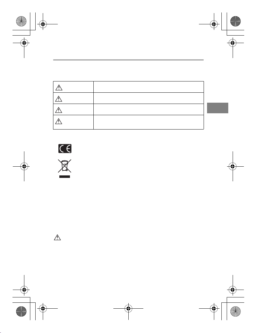
An exclamation mark enclosed in a triangle alerts you to important operating
and maintenance instructions in the documentation provided with the product.
DANGER
WARNING
CAUTION
If the product is used without observing the information given under this s ymbol,
serious injury or death may result.
If the product is used without observing the information given under this s ymbol,
injury or death may result.
If the product is used without observing the information given under this s ymbol,
minor personal injury, damage to the equipment, or loss of valuable d ata may
result.
For customers in Europe
“CE” mark indicates that this product complies with the European
requirements for safety, health, environment and customer protection. “CE”
mark cameras are intended for sales in Europe.
This symbol [crossed-out wheeled bin WEEE Annex IV] indicates separate
collection of waste electrical and electronic equipment in the EU countries.
Please do not throw the equipment into the domestic refuse.
Please use the return and collection systems available in your country for the
disposal of this product.
For customers in USA
FCC Notice
This device complies with part 15 of the FCC rules. Operation is subject to the following two
conditions: (1) This device may not cause harmful interference, and (2) this device must
accept any interference received, including interference that may cause undesired
operation. Any unauthorized changes or modifications to this equipment would void the
user’s authority to operate.
For customers in CANADA
This Class B digital apparatus complies with Canadian ICES-003.
DANGER
z This product is fitted with a high voltage circuit. Never dismantle or
modify it. It may cause burns by a short circuit.
z Do not use this product in places with the risk of combustible and
explosive gas present in the air. It may cause a fire or an explosion.
z Do not use the flash pointing to the driver etc. It may cause a serious
accident.
EN
EN 3
Page 4
r2090_e_00.book Page 4 Thursday, May 1, 2008 6:29 PM
WARNING
z Never use the flash in front of the eyes especially for infants or children
within 1 m. It may cause permanent vision impairment, etc.
z Keep the flash and batteries out of the reach of infants and children.
There is the possibility of the occurrence of the following types of
accidents:
• Swallowing of small parts. Please consult a physician immediately
if any parts have been swallowed.
EN
• Triggering of the flash in front of the eyes may cause permanent
vision impairment etc.
• Injury from parts of the body getting caught in parts which open and
close.
z If the following cases occur regardless of use on land or underwater*,
stop using it and turn off the power then remove the batteries
immediately. Please consult your local service station or dealer:
• If water or foreign objects come into contact with the electronic flash inside.
• If water penetration can be seen on the inside of the flash.
• If the product is in some way broken or internally exposed do not touch
it under any circumstances. Regardless of the batteries being
inserted, there is the possibility of an electrical shock by a short circuit.
* When using in water, come to the surface as fast as possible, however, keeping
in mind the needed time to come to the surface and the necessary
decompression time, wipe the body of any water and take out the batteries.
z Do not store the flash in locations with high humidity or dust and much
dust. It may cause a fire or an electrical shock.
z Do not use the flash when covering the light-emitting part with an easily
burnable item, such as a handkerchief.
z Do not touch the light-emitting part with your hand soon after the
continuous emission. It may cause burns.
z The grease for silicone O-ring for this product is not edible.
CAUTION
z If a bad smell, abnormal noise, deformation or smoke occurs stop use
immediately, turn off the power, and remove the batteries. Be careful
when removing the batteries as they may be hot. Contact your local
service station or dealer before using the product, as it may cause a fire
or burns.
EN 4
Page 5
r2090_e_00.book Page 5 Thursday, May 1, 2008 6:29 PM
z Do not place this product at locations with abnormally high or
abnormally low temperatures or at locations with extreme temperature
changes. The product may deteriorate or may cause a fire.
z
Do not alter the battery compartment or try to insert any foreign objects into it.
z Do not store the flash at the locations subject to vibrations. It may cause
malfunction.
z Opening and closing at locations with sand, dust, or dirt may impair the
waterproof characteristic and cause water leakage. This should be
avoided.
z This product has been designed and manufactured for use at a water
depth within 60 m. Please note that diving at depths in excess of 60 m
may cause deformation or damage to this product. In this case, water
penetration may occur.
z Rough handling, such as jumping into the water with the flash in your
hand or in an outside pocket or throwing the flash into the water could
lead to water penetration. Please always take care when handing it
from hand to hand etc.
z Before traveling by air, please make sure to remove the O-ring, otherwise
the difference in air pressure may make it impossible to open the flash.
Battery handling precautions
Follow these important guidelines to prevent batteries from leaking,
overheating, burning, exploding, or causing electrical shocks or burns.
DANGER
z
Never heat or incinerate batteries. It could cause a fire or an explosion etc.
z Never contact terminals (+) and (-) with metal.
z Take precautions when carrying or storing batteries to prevent them
from coming into contact with any metal objects such as jewelry, pins,
etc. It may cause burns and an injury by short circuit.
z Never store batteries where they will be exposed to direct sunlight, or
subjected to high temperatures in a hot vehicle, near a heat source, etc.
It may cause burns or an injury by battery fluid leaks, overheating or an
explosion.
z Do not use solder, transform, modify or dismantle the batteries. There
is the risk of destroying the terminal safety valve and the scattering of
internal contents. It may cause a fire or an explosion.
EN
EN 5
Page 6
r2090_e_00.book Page 6 Thursday, May 1, 2008 6:29 PM
z Do not connect the batteries to a power socket or car cigarette lighter.
It could cause a fire or an explosion etc.
z If battery fluid gets into your eyes, flush your eyes immediately with
clear, cold running water and seek medical attention immediately.
WARNING
z Keep batteries dry at all times.
z Do not touch the batteries with wet hands. It may cause electrical
shocks or malfunctions.
EN
z To prevent batteries from leaking, overheating, or causing a fire,
explosion or injury:
• Use only batteries recommended for use with this product.
• Never mix batteries (old and new batteries, charged and uncharged
batteries, batteries of different manufacture or capacity, etc.).
• Never attempt to charge alkaline or lithium batteries.
• Insert the batteries carefully with the correct polarity as described in
the operating instructions. Do not insert batteries forcibly into the
battery compartment.
• Never use batteries if their body is not covered by the insulating
sheet or if the sheet is torn, as this may cause fluid leaks, fire, or
injury.
• Never use batteries if their body is not covered by the insulating
sheet or if the sheet is torn even if they are sold as new ones.
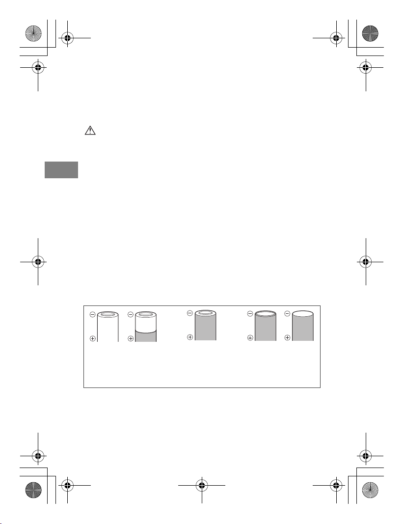
z The following batteries cannot be used:
Batteries whose bodies are
only partially or not at all
covered by an insulating sheet.
Batteries whose - terminals
are raised, but not covered
by an insulating sheet.
Batteries whose terminals are
flat and not completely covered
by an insulating sheet. (Such
batteries cannot be used even
if the - terminals are partially
covered.)
z If NiMH batteries are not charged within the specified time, stop
charging them and do not use them. Please read the manual carefully
to use the rechargeable batteries.
z Do not use batteries if they are cracked or broken. It may cause an
explosion or overheating.
EN 6
Page 7
r2090_e_00.book Page 7 Thursday, May 1, 2008 6:29 PM
z If a battery leaks, becomes discolored or deformed, or becomes
abnormal in any other way during operation, stop using it. It may cause
a fire or an electrical shock. Please contact your local service station or
dealer.
z Do not remove batteries immediately after using them. Batteries may
become hot during prolonged use, which may cause burns.
z If a battery leaks fluid onto your clothing or skin, remove the clothing
and flush the affected area with clean, running cold water immediately.
If the fluid burns your skin, seek medical attention immediately.
z Never subject batteries to strong shocks or continuous vibration.
z Always remove batteries if they are not used for a long period.
Otherwise, batteries may become overheated, leak fluid or cause a fire
or an injury.
CAUTION
z Keep batteries’ terminals clean. If they are not clean from sweat or
grease, it may cause contact failure. Clean them with a dry cloth.
z Using batteries at a low temperature may cause a shorter battery life or
lower performance. Using the batteries at a moderate temperature will
restore the performance.
z Before going on a long trip, and especially before traveling abroad,
purchase an ample supply of extra batteries. The recommended
batteries may be difficult to obtain while traveling.
EN
EN 7
Page 8
r2090_e_00.book Page 8 Thursday, May 1, 2008 6:29 PM
About O-ring
Please note the following points to use the O-ring.
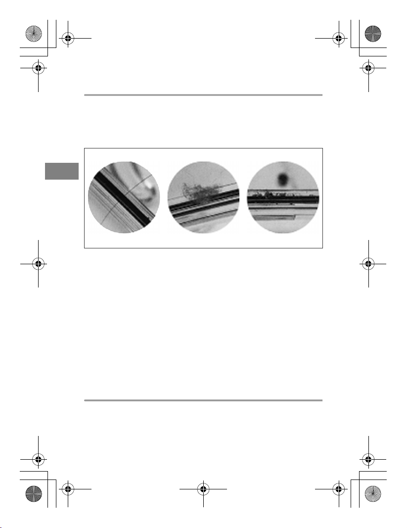
z When sealing this product, make sure that no hairs, fibers, sand
particles or other foreign matter stick not only to the O-ring, but also to
the contact surface. Even a single hair or a single grain of sand may
cause water leakage. Please check with special care.
Examples of foreign matter sticking to the O-ring
EN
Hair Fibers Grains of sand
z The O-ring is a consumption product. Please replace it at least once a
year with a new one. Also perform maintenance with every use.
z Deterioration of the O-ring will progress according to the conditions of
use and the storage conditions. Immediately replace the O-ring with a
new one if it is damaged, shows cracks, or has lost its elasticity.
z At the time of O-ring maintenance, clean the inside of the O-ring groove
and confirm the absence of dirt, dust, sand, and other foreign matter.
z Apply the specified silicone O-ring grease to the O-ring.
z The waterproof function is not effective when the O-ring is not installed
correctly. When installing the O-ring, take care that it does not project
from the groove and that it is not twisted. Also, when installing the
battery cap, close it after confirming that the O-ring has not come out of
the groove.
Handling the product
z Use or storage of the product at the following locations may cause
defective operation, defects, trouble, damage, a fire, internal clouding,
or water leakage. Always avoid these locations:
• Place in direct sunlight such as in a closed vehicle.
EN 8
Page 9
r2090_e_00.book Page 9 Thursday, May 1, 2008 6:29 PM
• Places where there are open fires.
• Places where water is deeper than 60 m.
• Places subject to vibrations.
• Places where high temperatures exist or high humidity and/or where
extreme differences in temperatures exist.
• Places where volatile chemicals are stored or used.
z Do not apply excessive force on the arm mount.
z In order to prevent the flash from overheating and losing quality, after
using the flash consecutively on full power, stop after 10 times for a
period of 10 minutes and allow the flash to cool down.
z When this product is not used for a long time, the O-ring may deteriorate,
diminishing its waterproof properties. Please check the O-ring before use.
z Do not use the following chemicals for cleaning, corrosion prevention,
prevention of fogging, repair or other purposes. When these are used
for the flash directly or indirectly (with the chemicals in vaporized state),
they may cause cracking or other problems.
Chemicals which cannot
be used
Volatile organic solvents,
chemical detergents
Anticorrosion agent Do not use anticorrosion agents. The metal parts
Adhesive Do not use adhesive for repairs or other purposes.
Do not clean the flash with alcohol, gasoline,
thinner or other volatile organic solvents or with
chemical detergents etc. Pure water or lukewarm
water is sufficient.
use stainless steel or brass, and washing with
pure water is sufficient.
When repair is required, please contact your local
service station or dealer.
Explanation
z Do not perform operations other than specified in this instruction
manual, do not remove or modify parts other than specified, and do not
use parts other than specified.
Any troubles in taking pictures or with the equipment resulting from the
above actions shall be outside the guarantee.
EN
EN 9
Page 10
r2090_e_00.book Page 10 Thursday, May 1, 2008 6:29 PM
Contents
Introduction............................................................................ 2
Please read the following items before use........................... 2
SAFETY PRECAUTIONS...................................................... 3
Battery handling precautions ................................................. 5
About O-ring .......................................................................... 8
Handling the product .............................................................8
1. Name of the Parts ..........................................................12
EN
Flash.................................................................................... 12
Checking the package contents........................................................ 12
Control panel ....................................................................... 14
2. Maintaining the Waterproof Function .............................15
Removing the O-ring ...........................................................15
Removing any sand, dirt, etc. .............................................. 16
Applying grease to the O-ring.............................................. 17
Installing the O-ring .............................................................17
3. Inserting the Batteries ....................................................18
Usable batteries (sold separately) ....................................... 18
Inserting the batteries .......................................................... 18
4. Mounting the Flash.........................................................20
Attaching to an arm .............................................................20
Connecting to a camera’s underwater case ........................ 21
Connecting using an underwater fiber optic cable (optional)........... 21
Connecting using an underwater TTL cable (optional)
and hot shoe cable (optional) ........................................................... 22
5. Basic Shooting ...............................................................23
Turning on the electronic flash ............................................23
Shooting ..............................................................................24
When the flash is connected using the underwater fiber
optic cable........................................................................................... 24
When the flash is connected using the underwater TTL cable ....... 25
6. Custom Setup ................................................................27
All reset................................................................................ 29
7. Using as Slave Flash .....................................................30
EN 10
Page 11
r2090_e_00.book Page 11 Thursday, May 1, 2008 6:29 PM
8. Handling After Shooting .................................................31
Wiping off any waterdrops ................................................... 31
Removing the batteries........................................................ 31
Cleaning the flash with pure water ......................................31
Drying the flash.................................................................... 32
Perform maintenance on the O-ring .................................... 32
Replace consumable products ............................................ 32
9. Appendix ........................................................................33
Q & A on the use of the UFL-2 ............................................ 33
Warning display list.............................................................. 37
Troubleshooting................................................................... 38
Specifications ......................................................................40
EN
EN 11
Page 12
r2090_e_00.book Page 12 Thursday, May 1, 2008 6:29 PM
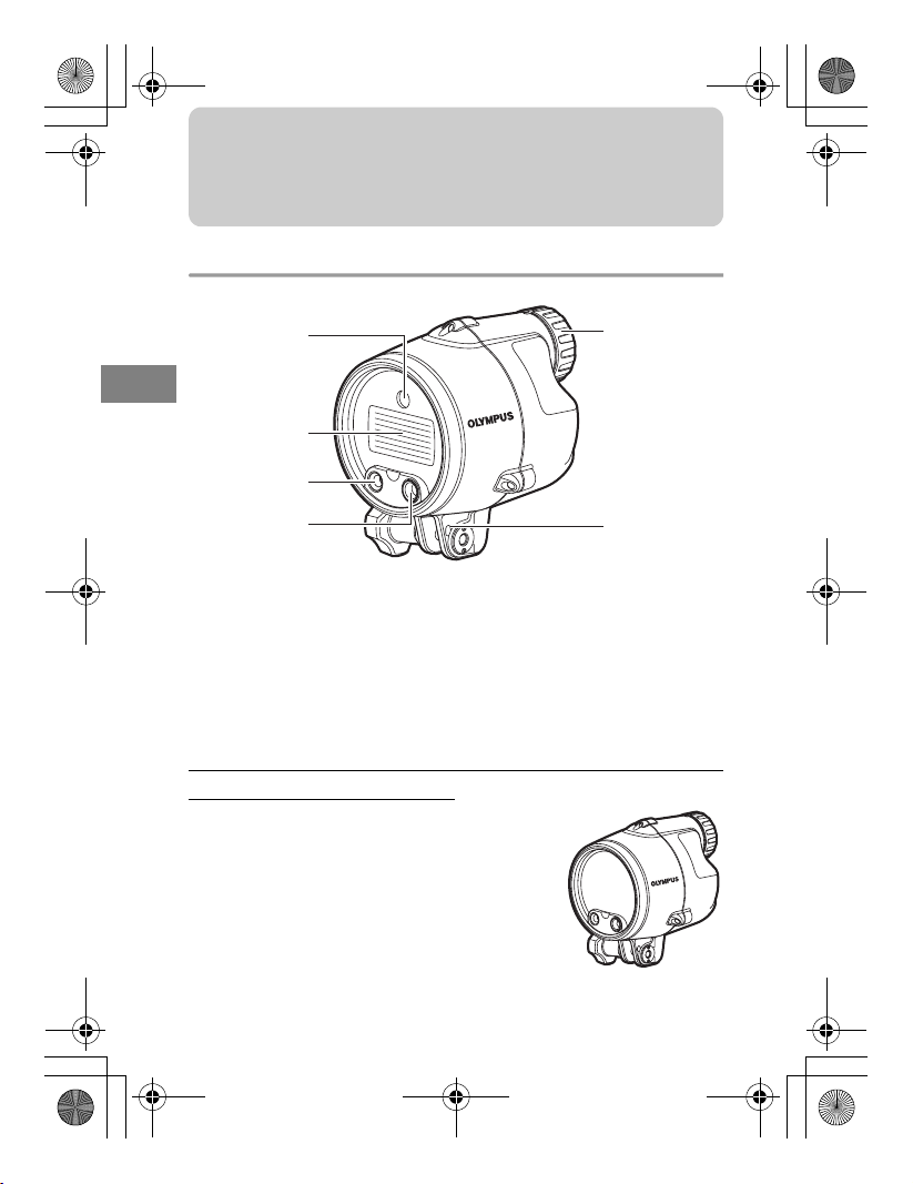
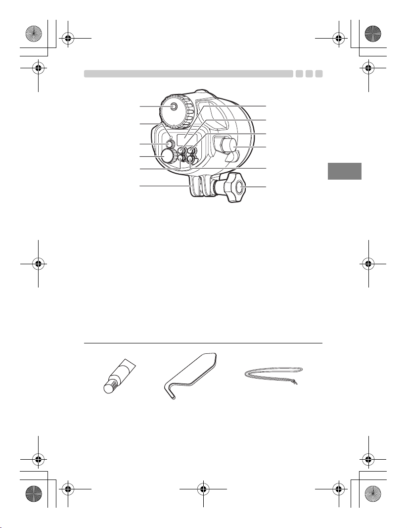
1. Name of the Parts
Flash
1
EN
2
3
4
1 AF illuminator light-emitting window
2 Light-emitting window
3 Fiber optic cable connector
Checking the package contents
The items listed at the right are included with the
electronic flash.
Contact your local service station or dealer if
accessories should be missing or damaged.
EN 12
6
5
4 Auto light-receiving window
5 Flash leash hole
6 Battery cap
Electronic flash
(main body)
Page 13
r2090_e_00.book Page 13 Thursday, May 1, 2008 6:29 PM
1
2
3
4
5
6
1 Gas outlet valve
2 AUTO CHECK lamp
3 TEST button/CHARGE lamp
4 Dial
5 ZOOM button
• Sets the firing angle within 12 - 42 mm
(24 - 85 mm with the 135 type).
6 Arm mount
b
a
0
9
8
7
7 Arm mount knob
8 POWER button
9 TTL cable connector
0 LIGHT button
• Press to light up the control panel for
about 15 sec.
a MODE button
b Control panel
EN
Silicone grease O-ring remover Flash leash
• Instruction manual (this manual)
• OLYMPUS distributor list
EN 13
Page 14

r2090_e_00.book Page 14 Thursday, May 1, 2008 6:29 PM
Control panel
Super FP flash
gP.26
Wide indication
gP.28
EN
ISO sensitivity
gP.29
Guide number
(GN)
gP.28
Notes on the information in this manual
The indications on the control panel may differ from those shown in the
illustration above depending on the setup of the electronic flash, the
camera in use, and the shooting conditions.
For example, the firing angle (ZOOM) can be displayed in either of the
following modes.
Flash control mode
gP.26
Setting display
Flash intensity control
gP.28
FOUR THIRDS
gP.28
Firing angle
(ZOOM)
mode
gP.13
Firing angle
(ZOOM)
value
gP.13
Aperture (F)
gP.29
Feet
gP.28
Meter
gP.28
1 FOUR THIRDS..... Focal length of a Four Thirds System digital camera
2 135......................... Focal length converted to an equivalent angle of
view on a 135 type (35 mm film) camera
The text in this manual employs the [FOUR THIRDS] display mode and
puts values in the [135] display mode inside parentheses, for example
“(xx mm with the 135 type)”. For the selection of the display modes, refer
to “6. Custom Setup” (gP.27).
EN 14
Page 15

r2090_e_00.book Page 15 Thursday, May 1, 2008 6:29 PM
2. Maintaining the Waterproof Function
This product is sealed with an O-ring. Maintenance of the waterproof
function is required even before using this product underwater for the first
time.
Removing the O-ring
Open the battery cap and remove the O-ring from the flash.
1 Insert the O-ring remover between the O-ring and the wall of the O-ring
groove.
2 Move the tip of the inserted remover under the O-ring. (Take care not to
damage the O-ring groove with the tip of the remover.)
3 Hold the O-ring with your fingertips after it has come out of the groove and
remove it from the flash.
EN
EN 15
Page 16

r2090_e_00.book Page 16 Thursday, May 1, 2008 6:29 PM
Removing any sand, dirt, etc.
After visually checking that dirt, sand, and other foreign matter has been
removed from the O-ring, check for damage and cracks by squeezing the
entire circumference of the O-ring lightly with your fingertips.
EN
Using a clean cloth free of fibers or a lint-free cotton swab, remove any
foreign matter attached to the grooves of the O-ring. Also remove sand
and dirt particles attached to the O-ring contact surface (battery cap side).
CAUTION
• When a mechanical pencil or a similar other sharp object is used to remove
the O-ring or to clean the inside of the O-ring groove, the O-ring may be
damaged and water leakage may be caused. Please use the provided
O-ring remover.
• When the O-ring is checked with the fingertips, take care not to stretch the
O-ring.
• Never use alcohol, thinner, benzene or similar solvents or chemicals
detergents to clean the O-ring. When such chemicals are used, it is likely
that the O-ring will be damaged or that its deterioration will be accelerated.
• Deterioration of the O-ring is accelerated by the conditions of use and the
storage conditions. Replace the O-ring even before a year has passed if it
shows signs of damage, cracking or loss of elasticity.
EN 16
Page 17

r2090_e_00.book Page 17 Thursday, May 1, 2008 6:29 PM
Applying grease to the O-ring
Make sure there is no dirt on your fingers
1
Apply the specified grease.
Spread the grease over
2
the O-ring.
Check that there is no
3
damage or irregularities
on the O-ring.
Apply the grease to the
4
O-ring contact surface.
or on the O-ring; then squeeze about 3
mm of grease onto your fingertip. (3 mm
is the most appropriate amount.)
Using two fingers and a thumb, spread
the grease over the O-ring while rubbing
it in. Use caution not to squeeze or pull
the O-ring too hard.
Once the grease has permeated
throughout the O-ring, check it for
damage or irregularities (both visually and
by touch). If you notice any abnormalities,
replace the O-ring with a new one.
Use any residual grease on your
fingertips to clean and lubricate the O-ring
contact surface on the battery cap.
Installing the O-ring
Confirm that no foreign matter is attached, apply a thin coat of the
accessory grease to the O-ring, and fit the O-ring into the groove. At this
time, confirm that the O-ring does not stick out from the groove.
CAUTION
• Always perform maintenance of the waterproof function even when the
battery cap has been opened to exchange the battery. Neglecting this
maintenance may result in water leakage.
• When the flash is not to be used for a long time, remove the O-ring from
the groove to prevent deformation of the O-ring, apply a thin coat of silicone
grease, and store it in a clean plastic bag.
• When drying is done with salt attached, it is likely that a function
impairment will be caused. After use, always wash off any salt.
EN
EN 17
Page 18

r2090_e_00.book Page 18 Thursday, May 1, 2008 6:29 PM
3. Inserting the Batteries
Usable batteries (sold separately)
Always use one of the following battery combinations:
AA alkaline batteries/AA NiMH batteries/AA lithium batteries/
AA oxyride batteries/AA NiCd batteries
• Manganese batteries are not to be used.
Inserting the batteries
EN
1 Carefully rotate the battery cap counterclockwise to remove it.
2 Install the batteries in the correct manner paying especial attention to match
the (+) and (-) marks.
3 Make sure to check that there is no foreign matter, rubbish etc. not only on
the O-ring but also on the contact surface (battery cap side).
4 Thinly apply the specified silicone O-ring grease to the O-ring.
5 Match the O mark on the battery cap (back side) with the O mark on the
flash and while pushing the battery cap, turn gently in a clockwise direction
until it can’t turn anymore.
• While putting the cap back on take special care so that the O-ring
does not project from the groove.
6
After replacing the battery cap tightly, turn it back slightly in a counterclockwise
direction and align the marks.
• After aligning the marks, make sure no O-ring can be seen.
12 45
EN 18
-
+
6
Alignment marks
Correct
(The O-ring can’t be seen)
O-ring
Incorrect
(The O-ring can be seen)
O Mark
Page 19

r2090_e_00.book Page 19 Thursday, May 1, 2008 6:29 PM
CAUTION
• While installing and exchanging batteries make sure to wipe the flash of
any water and always use dry hands. Pay especial attention for any drips
from hair and wetsuits.
• Turn gently and slowly when taking on/off the battery cap. If the cap is
turned too quickly the O-ring may get caught and cause a leakage.
• When securing the battery cap tightly, make sure to turn it back slightly in
a counterclockwise direction and align the flash’s mark with the battery
cap’s mark. If the battery cap is secured too tight beyond the alignment
marks, the battery cap may not be removed due to water pressure etc.
• Make sure to use the same type of batteries.
• Always replace both batteries at the same time.
EN
EN 19
Page 20

r2090_e_00.book Page 20 Thursday, May 1, 2008 6:29 PM
4. Mounting the Flash
Attaching to an arm
Attach the flash to the arm. When attaching the arm to the camera, make
sure to read the arm’s instruction manual on how to attach the arm.
1 Loosen the arm mount knob by turning in an counterclockwise direction.
2 Place part A in the space between the arm mount.
EN
3 Turn the loosened knob, in step 1, in a clockwise direction all the way to
clamp the arm to the flash.
• Be sure to double check the arm is firmly fastened to the flash.
1
A
If the case of necessity, attach the flash leash to the flash leash hole and
tie it to the underwater case, etc.
2
3
EN 20
Page 21

r2090_e_00.book Page 21 Thursday, May 1, 2008 6:29 PM
Connecting to a camera’s underwater case
There are two ways to connect the flash to a camera’s underwater case.
To learn what connection method to use, refer to the instruction manual
that comes with your camera’s underwater case.
Connecting using an underwater fiber optic cable (optional)
• Insert the plugs of the underwater fiber optic cable into the connector
on the camera’s underwater case and on the flash’s fiber optic cable
connector, all the way in until they stop.
• You can connect and disconnect the underwater fiber optic cable while
under water.
• For further details, refer to the instruction manuals of the underwater
fiber optic cable (optional) and the camera’s underwater case.
EN
EN 21
Page 22

r2090_e_00.book Page 22 Thursday, May 1, 2008 6:29 PM
Connecting using an underwater TTL cable (optional) and hot
shoe cable (optional)
Alignment mark
EN
1 Verify that the flash is completely dry.
2 Remove the cap of the TTL cable connector on the flash. Inspect the O-ring
and apply a thin coating of the supplied silicon grease.
3 Remove the cap from the TTL cable’s connector.
4 Align the TTL cable’s plug and the TTL cable connector on the flash at their
alignment marks and insert the cable straight.
5 Turn the lock dial on the cable’s connector until it stops to firmly attach the
connector.
6 In the same way, attach the TTL cable’s plug to the TTL cable connector on
the camera’s underwater case.
• For details about connecting the hot shoe cable (optional), refer to
the instruction manual of the camera’s underwater case.
The following optional accessories are recommended.
Underwater fiber optic cable PTCB-E02
Underwater TTL cable PTCB-E01
Hot shoe cable PHCB-01
EN 22
Page 23

r2090_e_00.book Page 23 Thursday, May 1, 2008 6:29 PM
5. Basic Shooting
Turning on the electronic flash
Connect the flash to the camera’s underwater case using a cable. After
turning on the camera and flash, be sure to check the remaining battery
power.
AUTO CHECK lamp
TEST button/
CHARGE lamp
Control panel
POWER button
1 Press the POWER button.
• The control panel is displayed and battery charging starts.
• Press the POWER button again to turn the electronic flash off.
2 Verify that the CHARGE lamp lights up.
• Replace the batteries if the time it takes for the CHARGE lamp to
light up exceeds the following values.
Alkaline or oxyride batteries 30 sec. or more
NiMH or lithium batteries 10 sec. or more
• If the CHARGE lamp and AUTO CHECK lamp blink simultaneously,
it means that the battery capacity is running low. In this case,
replace the batteries.
3 Press the TEST button to test the flash activation.
EN
EN 23
Page 24

r2090_e_00.book Page 24 Thursday, May 1, 2008 6:29 PM
Shooting
When the flash is connected using the underwater fiber optic
cable
Following is an explanation of the basic method for taking pictures with the
flash connected to a camera’s underwater case using the underwater fiber
optic cable. Refer to your camera’s instruction manual for details about the
camera’s operation.
EN
1 Press the MODE button on the flash repeatedly to set the flash to RC mode.
2 Set the camera’s RC mode to ON and set the camera’s built-in flash so as
to allow it to be emitted.
• Set the flash mode and the flash intensity on the camera.
3 While holding the MODE button pressed down, turn the dial to select the
channel and group.
Channel : Set the same channel, between 1 and 4, on the camera
and flash.
Group : You can control up to 3 groups (A, B and C) of flash arrays
with different flash modes and other settings. On the
electronic flash set in advance the group with which the
flash will be emitted.
4 Press the ZOOM button to adjust the firing angle.
5 After the shooting preparations are completed, take some test shots to
check the flash operation and the resulting images.
Channel
RC mode
Group
MODE button
EN 24
Page 25

r2090_e_00.book Page 25 Thursday, May 1, 2008 6:29 PM
When the flash is connected using the underwater TTL cable
Let’s try shooting pictures using the TTL AUTO mode. In TTL AUTO mode
the flash intensity is controlled automatically according to the camera’s
settings.
Flash control mode
AUTO CHECK lamp
Firing angle
Displayed according to the
focal length of the lens.
Light control range
MODE button
1 Set the camera’s shooting mode to one of the underwater modes.
2 Press the MODE button of the electronic flash repeatedly to set the flash
control mode to [TTL AUTO].
3 Press the shutter button halfway.
• Shooting information will be communicated between the camera
and the electronic flash and the light control range will be displayed
on the control panel.
• If the subject is not within the light control range, adjust the distance
to the subject.
• The light control range will vary according to the camera’s setup
(ISO sensitivity, aperture value and focal length of the lens).
4 Press the shutter button fully.
• When flash activation has been performed correctly, the AUTO
CHECK lamp blinks for about 5 seconds after the shutter is
released.
EN
EN 25
Page 26

r2090_e_00.book Page 26 Thursday, May 1, 2008 6:29 PM
Select the flash control mode according to the subject and the shooting
conditions. Press the MODE button repeatedly to change the flash control
mode.
Control panel display Explanation
EN
The flash light intensity is controlled automatically according to
the camera’s setup. The flash will be adjusted based on the
brightness taken through the camera’s lens.
The flash light intensity is controlled automatically according to
the camera’s setup. The flash will be adjusted based on the
brightness captured by auto light-receiving window on the
electronic flash.
The flash is emitted according to the guide number (GN) set
using the dial. The optimum shooting distance (land shooting)
according to the camera’s setup will be displayed.
Super FP flash. This mode allows you to use flash photography
even at shutter speeds faster than the flash synchronization
s
speed of the camera. In AUTO mode the flash light intensity is
controlled automatically. In MANUAL mode the flash is emitted
according to the guide number selected.
CAUTION
• Certain modes may be unavailable depending on the shooting mode set
on the camera and the functions of the camera in use.
• It is not possible to select an unavailable mode.
EN 26
Page 27

r2090_e_00.book Page 27 Thursday, May 1, 2008 6:29 PM
6. Custom Setup
Custom setup allows you to customize the electronic flash to suit your
preferences.
MODE button
1 Press and hold the MODE button for more than 2 seconds, until the setup
mode display appears in the control panel.
2 Press the MODE button to select the setup mode.
3 Turn the dial to select the value.
4 Press and hold the MODE button for more than 2 seconds to confirm the
setup.
EN
Setup mode
AF illuminator
Flash cable
Mode display Value display
MODE button Dial
Function
AF illuminator is
activated according
to the control from
the camera.
AF illuminator is
off.
Keep this option
set to ON at all
times.
Default
value
A
on
EN 27
Page 28

r2090_e_00.book Page 28 Thursday, May 1, 2008 6:29 PM
EN
Setup mode
Firing angle
(ZOOM) display
Distance
display unit
Flash intensity
control
Wide indication
Guide number
display
Mode display Value display
MODE button Dial
Function
Firing angle is
displayed in terms
of the lens focal
length of a FOUR
THIRDS camera.
Firing angle is
converted into the
focal distance of
the 135 type.
This allows the
flash to be used in
the same feeling as
the flash for a 135
type (35 mm film)
camera.
Distance is
displayed in meter.
Distance is
displayed in feet.
Flash intensity
cannot be
adjusted.
Flash intensity can
be adjusted
between -3 and +3.
When the camera’s
flash intensity
control mode is set,
the actual flash
light intensity will
be the total of the
flash intensity
value set on the
electronic flash and
that set on the
camera.
Blinks when the
focal length of the
lens is shorter than
12 mm (24 mm
with the 135 type).
The wide indication
is disabled.
The flash intensity
is displayed in a
guide number.
The flash intensity
is displayed in a
flash intensity ratio.
Default
value
4-3
m
OFF
on
on
EN 28
Page 29

r2090_e_00.book Page 29 Thursday, May 1, 2008 6:29 PM
Setup mode
ISO, F
communication
in AUTO mode
• A vailable only
in AUTO
mode, with
cameras with
communicatio
n capability.
ISO sensitivity
selection in
AUTO mode
• Works with a
camera
without
communicatio
n capability.
Also works
with a camera
with
communicatio
n capability
when the
ISO, F
communicatio
n is set to
[OFF].
Mode display Value display
MODE button Dial
Function
The ISO sensitivity
and aperture value
setup will be
adjusted
automatically by
the camera.
You can adjust the
ISO sensitivity and
aperture value on
the electronic flash.
The ISO sensitivity
can be set with the
dial.
All reset
All reset resets the custom setups to the factory default settings.
LIGHT button
MODE button
Default
value
on
100
EN
1 Press the MODE and LIGHT buttons simultaneously for 2 or more seconds
to reset to default settings.
• The distance display unit (m/ft) is not altered by the all reset
operation.
EN 29
Page 30

r2090_e_00.book Page 30 Thursday, May 1, 2008 6:29 PM
7. Using as Slave Flash
The electronic flash is equipped with the slave function. In this function
you can emit the flash by synchronizing it to the emission of another flash.
EN
Slave mode
MODE button
1 Connect this flash to the flash to which you want to synchronize it using the
underwater fiber optic cable.
2 Press the MODE button of the electronic flash repeatedly to set the flash
control mode to [SL AUTO] or [SL MANUAL].
[SL AUTO] : While holding the MODE button pressed down, turn
the dial to set the ISO sensitivity. Set the dial according
to the aperture value of the lens.
[SL MANUAL] : Turn the dial to set the guide number (GN).
3 Setup the camera in the following way.
• Set cameras with slave mode to slave mode.
• Set cameras with manual flash emission mode to manual flash
mode. This setup will function also if you attach an external flash
with manual flash emission mode to the camera.
CAUTION
• The slave flash mode cannot be used with cameras that perform a preflash because the electronic flash will be emitted simultaneously with the
pre-flash.
• If other photographers are shooting using flash, the electronic flash may
react to those lights and be emitted.
• The firing angle of the flash cannot be controlled automatically so be sure
to check it beforehand. Pressing the ZOOM button on the electronic flash
once will display the firing angle for about 2 seconds. You can change the
firing angle by pressing ZOOM again while the current firing angle is
displayed. Verify whether the firing angle setting is appropriate or not by
performing a test shot.
EN 30
Page 31

r2090_e_00.book Page 31 Thursday, May 1, 2008 6:29 PM
8. Handling After Shooting
Wiping off any waterdrops
After underwater shooting, remove any drops of water from the flash.
Use pressurized air or lint-free cloth to carefully wipe away any water from
the buttons, the battery cap and the gaps between the battery cap and the
body of the flash.
CAUTION
• Waterdrops may spill into the flash when the battery cap is removed,
especially when they remain between the flash and the battery cap. Take
special care to wipe off all waterdrops.
Removing the batteries
1 Remove the battery cap and take out the batteries.
2 After removing the batteries, be sure to replace the battery cap.
CAUTION
• Before opening the battery cap, make sure that your hands or gloves are
free of sand, fibers, etc.
• Do not open or close the battery cap at locations where water or sand may
be sprayed. When this cannot be avoided because you have to exchange
the battery, place a sheet upwind from some object and take care that no
water or sand is sprayed.
• Never touch the batteries when your hands are wet with salt water.
Note :
Moisten a towel etc. in advance with pure water and keep it in a plastic bag
so that you can wipe the salt from your hands and fingers before handling
the flash.
EN
Cleaning the flash with pure water
Please make sure to use pure water. After using this flash, seal it again
with the battery cap and rinse it with pure water as soon as possible. After
use in salt water, the flash should be immersed for an extended period of
time in a bowl of pure water to remove any salt water or salt residues.
EN 31
Page 32

r2090_e_00.book Page 32 Thursday, May 1, 2008 6:29 PM
CAUTION
• Leakage may occur to some parts if exposed to high water pressure.
• Operate the switches of the flash when it is in clean tap water to remove
any salt from their shafts. Do not disassemble the flash for cleaning.
• If the flash is dried before all salt has been removed, this could affect its
performance. Always make sure all salt has been removed.
Drying the flash
EN
After washing the flash, dry it with a clean, soft, lint-free cloth. Then, leave
it to dry completely in a well-ventilated location protected from direct
sunlight.
CAUTION
• Never use hot air from a hair dryer or other appliance to dry the flash. This
could deteriorate or deform the flash and O-ring and lead to water
penetration.
• When wiping the flash, take care not to scratch it.
Perform maintenance on the O-ring
Always carry out maintenance on the O-ring after use, to maintain
optimum waterproofing performance.
See “2. Maintaining the Waterproof Function” (gP.15)
Replace consumable products
• The O-ring is a consumable product. Independent of the number of
times the flash is used, it is recommended that the O-ring should be
replaced by a new one at least once a year.
• Deterioration of the O-ring is accelerated by the conditions of use and
the storage conditions. Replace the O-ring even before a year has
passed if it shows signs of damage, cracking or loss of elasticity.
Note :
Please use original Olympus silicone O-ring grease and the O-rings. These
products can be purchased at an Olympus service station.
EN 32
Page 33

r2090_e_00.book Page 33 Thursday, May 1, 2008 6:29 PM
9. Appendix
Q & A on the use of the UFL-2
Q1: What cautions must be observed when taking off the battery cap?
A1: Pay attention to the following points:
1 Take the cap off in a place where it is safe from spray and the
scattering of sand.
2 Wipe off all water drops in the gap between the battery cap and the
body, and any place that is uneven. As when taking off the cap water
drops may run inside.
3 Make sure there is no rubbish, hair or other foreign matter sticking
to the O-ring and O-ring contact surface (battery cap side).
4 Before returning the battery cap, make sure the O-ring is correctly
aligned with the O-ring groove.
5
Gently turn the battery cap. If it is turned too quick the O-ring may get
caught or not align correctly with the groove and may result in leakage.
Q2:
What cautions must be observed when using and storing the flash?
A2: 1 When the flash is used, left or stored at the following locations,
defective operation or trouble may be caused. Always avoid such
locations:
• Places where the flash can reach high temperatures under direct
sunlight or in a car, places with extremely low temperatures, and
places with extreme temperature variations.
• Places with open fire
• Places with volatile substances
• Places with vibrations
2 The following instances could lead to operational problems and/or
damage to this flash. Avoid knocks and sudden increases in
pressure caused by:
• Hitting other objects
• Dropping
• Placing heavy objects on top of the flash
3 When the flash is not used for a long time, trouble from formation of
mold etc. may be caused. Before use, confirm the operation of all
operating parts and perform the O-ring maintenance.
See “2. Maintaining the Waterproof Function” (gP.15)
EN
EN 33
Page 34

r2090_e_00.book Page 34 Thursday, May 1, 2008 6:29 PM
Q3: How to handle the flash after use?
A3: After using the flash, remove the batteries at once and seal it again
with the battery cap and then rinse it in pure water. After use in salt
water, you should immerse the flash for an extended period of time
in pure water. Operate the switches when it is in clean tap water to
remove any salt from their shafts. After rinsing, remove moisture
with a dry cloth free of salt, and dry the flash in the shade. Never
use hot air from a hair dryer or other appliances to dry the flash,
EN
and never place it in direct sunlight to dry, as this could deform,
discolor, damage or deteriorates the flash and O-ring.
• The inner side of the flash should be wiped with a soft, lint-free
cloth.
• Remove the O-ring, wipe off the attached foreign matter such as
salt, sand and dirt, also clean the grooves in which O-ring has
been fitted and the surface in contact with the O-ring (battery cap
side), and dry all of them.
• When removing an O-ring from the groove, do not use a sharp
object to avoid damaging the O-ring and causing leaks. Be
always sure to use the provided remover for removing the
O-ring.
Q4: What are the causes for entry of water?
A4: The main causes for the entry of water are shown below. Please
check them most carefully.
1 Forgetting to install the O-ring
2 The O-ring is partly or completely outside the groove
3 Damage, deterioration, or deformation of the O-ring
4 Sand, fibers, hair or other foreign matter on the O-ring
5 Sand, fibers, hair or other foreign matter on the O-ring groove or the
O-ring contact surface
6 Throwing the flash from a boat into the water, jumping with the flash
into the water, or other sudden application of strong forces onto the
flash. When entering the water, hand the flash over gently or avoid
impacts in other ways.
EN 34
Page 35

r2090_e_00.book Page 35 Thursday, May 1, 2008 6:29 PM
Q5: What are the important points for O-ring maintenance?
A5: Please observe the following items.
1 Never use alcohol, thinner, benzene or similar organic solvents or
chemical detergents to clean the O-ring. When such chemicals are
used, it is to be feared that the O-ring will be damaged or that its
deterioration will be accelerated.
2 Use the original Olympus silicone O-ring grease (white cap). The
grease of other companies are not suitable for this silicone O-ring,
and use of such grease may cause deterioration of the surface and
impairment of the waterproof function.
3 In order to avoid deformation of the O-ring when the flash is not used
for a long time, remove the O-ring from the flash, apply a thin coat of
the special grease, and store the O-ring in a clean plastic bag. For
reuse, confirm that the O-ring is free of damage and cracks, that it
has sufficient elasticity, that the surface is free of stickiness and
other abnormalities, and use it after applying a thin coat of the
special grease. Excessive application of grease does not improve
the waterproof function or the maximum level of pressure. However,
it may facilitate attachment of sand, dirt, etc. A thin, uniform coat
produces the best result.
4 The O-ring is a consumable product. Replace it at least once a year.
5 Deterioration of the O-ring is accelerated by the use conditions and the
storage conditions. Replace the O-ring immediately by a new one if it
shows signs of damage, cracking or loss of elasticity.
Q6: What are the important points for the flash maintenance?
A6: Please observe the following items. Never use the following
chemicals for cleaning, corrosion protection, repair or other
purposes:
• Never use alcohol, thinner, benzene or similar volatile organic
solvents or chemical detergents to clean the flash. Pure water or
lukewarm water is sufficient for cleaning.
• Do not use anticorrosion agents on the metal parts. The metal
parts are made of aluminum, brass or stainless steel. Cleaning
with pure water is sufficient.
• Do not use adhesive for repairs or other purposes. When repair
is required, please contact your local service station or dealer.
EN
EN 35
Page 36

r2090_e_00.book Page 36 Thursday, May 1, 2008 6:29 PM
Q7: Please tell me about repairs.
A7: Please contact your local service station or dealer, if repairs should
be necessary. Do not try to repair, disassemble or modify the flash
yourself. Repair, disassembly or modification by you or third parties
not authorized by Olympus invalidates the guarantee.
Q8: What are the model numbers of the UFL-2 accessories?
A8: The following accessories are being sold.
EN
1 O-ring for the UFL-2 body (POL-U1): This is a silicone rubber O-ring
packing to be installed in the UFL-2 body to make it waterproof.
2 Silicone O-ring grease (PSOLG-1/2/3): This is a special grease for
silicone O-ring maintenance.
* Please contact your local service station or dealer when
replacement is required. Replacement will be made against
payment.
EN 36
Page 37

r2090_e_00.book Page 37 Thursday, May 1, 2008 6:29 PM
Warning display list
Warning details
In AUTO mode:
Out of light control range
In MANUAL mode:
Subject too close
In FP MANUAL mode:
Subject too close
Control panel
display
(camera without
communication
capability)
(camera without
communication
capability)
Remedy
Change the camera’s ISO sensitivity or
aperture setting.
When the optimum shooting distance is
less than 0.6 m (1.9 ft.), the displayed
value blinks to alert you that the
shooting range does not match the light
emission area of the flash.
1 Change the camera’s ISO sensitivity
or aperture setting.
2 Change the guide number setting.
1 Change the camera’s ISO sensitivity
or aperture setting.
2 Change the guide number setting.
EN
EN 37
Page 38

r2090_e_00.book Page 38 Thursday, May 1, 2008 6:29 PM
Troubleshooting
Q: When are test flash activation and auto checking effective?
A: Correct activation of the flash can be confirmed by checking the
AUTO CHECK lamp (AUTO modes only).
Q: Why doesn’t the flash control mode change when I press the
MODE button?
A: When the electronic flash is connected to certain types of
EN
communication-capable cameras, the flash control mode can only
be controlled from the camera.
Q: What is the recommended white balance setting for the
camera when using the electronic flash?
A: The auto white balance mode is recommended. If you use the
manual white balance mode, set the color temperature to around
5400K. Note that the color temperature varies depending on the
flash intensity.
Q: The AF illuminator does not light up. What is wrong?
A: The AF illuminator only works when you use the electronic flash
with Olympus Four Thirds System digital SLR cameras. It does not
work with other cameras.
Q: The light control range is not displayed on the control panel.
What is wrong?
A: The light control range is not displayed in the following cases:
• When the extension tube EX-25 (optional) is used.
• When the ISO sensitivity and aperture value are out of the
setting range.
Q: The flash wasn’t emitted when shooting in RC mode. What is
wrong?
A: Verify that the camera and the electronic flash are set to the same
channel and that the group is set correctly.
EN 38
Page 39

r2090_e_00.book Page 39 Thursday, May 1, 2008 6:29 PM
Q: How can I find out if my camera is compatible with wireless
flash?
A: You can use the RC mode only with cameras compatible with the
Olympus wireless RC flash system. With other cameras you may
be able to use the electronic flash as slave flash if the camera’s
built-in flash can be set to slave flash mode or manual flash mode.
For details, refer to the camera’s instruction manual.
Q: When the Olympus digital camera entered the sleep mode, the
control panel on the electronic flash turned off as well (while
connected with the underwater TTL cable). Is this normal?
A: Yes, it is normal. When the camera enters the sleep mode, the
electronic flash does as well. When the camera wakes up, so does
the electronic flash. After approximately 15 minutes in sleep mode,
the electronic flash turns off. In such a case, press the POWER
button to turn the electronic flash back on.
Q: Does the electronic flash also turn off when the Olympus
digital camera is turned off (while connected with the
underwater TTL cable)?
A: When the camera is turned off, the electronic flash enters the sleep
mode. After approximately 15 minutes, the electronic flash
automatically turns off. In such a case, press the POWER button to
turn the electronic flash back on.
Q: Why did the electronic flash automatically turn off?
A: The electronic flash automatically turns off in RC mode and slave
mode when no operations are performed for 60 minutes. When
connected to a camera without communication capability, the
electronic flash enters the sleep mode if it is not operated for about
15 minutes. After another 15 minutes, the power turns off.
EN
EN 39
Page 40

r2090_e_00.book Page 40 Thursday, May 1, 2008 6:29 PM
Specifications
MODEL NO. UFL-2
Type Electronic flash for the Olympus underwater-
Guide Number Automatic switching
EN
Firing angle Automatic switching
Flash emission count AA alkaline batteries:
Recharge time (Full flash)
Flash modes TTL AUTO, AUTO, MANUAL, FP TTL AUTO,
Light Temperature 5400 K
Waterproofing 60 m
Operating
environment
temperature
Power supply AA alkaline batteries/AA NiMH batteries/
Dimensions 120 mm (W) × 152 mm (H) × 135 mm (D)
Weight 750 g (without batteries)
* We reserve the right to change the external appearance and the
specifications without notice.
EN 40
use digital camera
36: When in 42 mm (85 mm with the 135 type)
20: When in 12 mm (24 mm with the 135 type)
(land shooting, flash intensity at FULL)
At 12 mm: Up/down 61°, Left/right 78°
(equivalent to image angle of 12 mm lens)*
At 42 mm: Up/down 21°, Left/right 28°
(equivalent to image angle of 42 mm lens)*
* ZOOM values are the FOUR THIRDS
camera values.
Approx. 100 times
AA NiMH batteries (2400 mAh):
Approx. 200 times
AA alkaline batteries:
Approx. 8 seconds
AA NiMH batteries (2400 mAh):
Approx. 6.5 seconds
FP MANUAL, RC, SL AUTO, SL MANUAL
0°C to 40°C (32°F to 104°F)
AA lithium batteries/AA oxyride batteries/
AA NiCd batteries (two)
(excluding protrusions)
Page 41

r2090_e_00.book Page 41 Thursday, May 1, 2008 6:29 PM
 Loading...