

Page 1

MAINTENANCE MANUAL
UES-40
ISSUE4
2008/01
Page 2

Page 3

UES-40
INTRODUCTION
Repair and maintenance of this product requires highly specialized knowledge and techniques.
We recommend that you contact an Olympus service center in your area if a problem develops with the
product.
If repairs or modifications are made by personnel not authorized by Olympus, the warranty is void, and
Olympus shall not be liable for damage that occurs to or as a result of use of the modified product.
Applicable Unit
• ELECTROSURGICAL UNIT UES-40 120 V
• ELECTROSURGICAL UNIT UES-40 220 V
Copyright
© 2004 Olympus Medical Systems Corp. All rights reserved.
Unauthorized reproduction or distribution in part or in whole is prohibited.
Trademarks
OLYMPUS is a registered trademark of the Olympus Corporation.
The company names, product names, and proprietary technical terms in this document are the trade-
marks or registered trademarks of their respective owners.
ISSUE4 INTRODUCTION
Page 4

UES-40
CONTENTS
Chapter 1: Product Specification..........................................1-1
1 Outline ...................................................................................................... 1-2
2 Specifications............................................................................................1-2
2-1 High-frequency output.................................................................................1-2
2-2 Safety functions.................................................... .......................................1-5
2-3 Additional features.......................................................................................1-6
2-4 Safety ..........................................................................................................1-7
2-5 Laws, regulations, and standards................................................................1-7
2-6 Others..........................................................................................................1-7
3 Operating Requirements...........................................................................1-8
4 Name and Function of Each Part............................................................1-10
4-1 Front panel (for 120 V and 220 V).............................................................1-10
4-2 Rear panel.................................................................................................1-13
5 Ports ....................................................................................................... 1-14
5-1 Foot switch port for MAJ-1258 ..................................................................1-14
5-2 Bipoler foot switch port for MAJ-1259........................................................1-14
5-3 System port ...............................................................................................1-15
6 System Diagram.....................................................................................1-16
6-1 Endoscopic Treatment with UES-40 - System Diagram............................1-16
6-2 Electrosurgical Treatment with UES-40 - System Diagram.......................1-18
Chapter 2: Troubleshooting...................................................2-1
1 Troubleshooting........................................................................................2-2
1-1 Troubleshooting list .....................................................................................2-3
2 Error Codes .............................................................................................. 2-7
2-1 Error-code list.......... ....................................................................................2-7
Chapter 3: Disassembly and Reassembly Procedure.........3-1
1 Precautions for disassembly and reassembly .......................................... 3-2
2 Disassembly procedure............................................................................3-3
2-1 Tools............................................................................................................3-3
2-2 Disassembly procedure...............................................................................3-4
3 Reassembly procedure...........................................................................3-16
3-1 Tools..........................................................................................................3-16
3-2 Reassembly procedure..............................................................................3-16
CONTENTS 1 ISSUE4
Page 5

UES-40
Chapter 4: Inspection.............................................................4-1
1 Preparation...............................................................................................4-2
2 Inspection Procedure................................................................................4-2
Chapter 5: Parts List...............................................................5-1
1 Exploded Parts Diagram...........................................................................5-2
2 Parts List...................................................................................................5-6
ISSUE4 2 CONTENTS
Page 6

Page 7

Chapter 1: Product Specification
Chapter 1:Product Specification
1 Outline .....................................................................1-2
2 Specifications...........................................................1-2
3 Operating Requirements..........................................1-8
4 Name and Function of Each Part...........................1-10
5 Ports.......................................................................1-14
6 System Diagram .................................................... 1-16
ISSUE4 1-1 Product Specification
Page 8

UES-40
1. Outline
The ELECTROSURGICAL UNIT UES-40 (UES-40) is designed for use in medical facilities
under doctor supervision in combination with designated reusable high-frequency instruments, endoscopes, and light sources in surgical procedures and treatment using endoscopes (fiber scopes, videoscopes, and rigid scopes) for the cutting and coagulation of living
tissue.
(1) Expanding the functions available with the UES-30
The UES-40 also offers an output system for use in physiological saline (TURis). TURis
frees surgeons from the need for a patient plate, and offers improved safety over conventional TUR is.
TURis (TUR in saline): A technique for cutting and ablation in physiological saline
TUR: Transurethral resection of the prostate
(2) Supports the use of multiple electrodes
(Separate settings can be used for each system: bipolar, monopolar, and saline.)
(3) The UES-40 features exclusive specifications and is compatible with EndoALPHA.
(4) For easier use, the front panel is designed at a 20° vertical orientation.
(5) The design of the UES-40 is coordinated with the VISERA Video System.
2. Specifications
2-1 High-frequency output
2-1-1 Output methods
• Bipolar system
• Monopolar system
• Saline system
2-1-2 Options
• Bipolar system
Cutting Mode: 1 option (Cut)
Coagulation Mode: 3 options (Soft 1, Soft 2, Hard)
• Monopolar system
Cutting Mode: 3 options (Pure, Blend, Uro)
Coagulation Mode: 3 options (Coag 1, Coag 2, Spray)
Product Specification 1-2 ISSUE4
Page 9
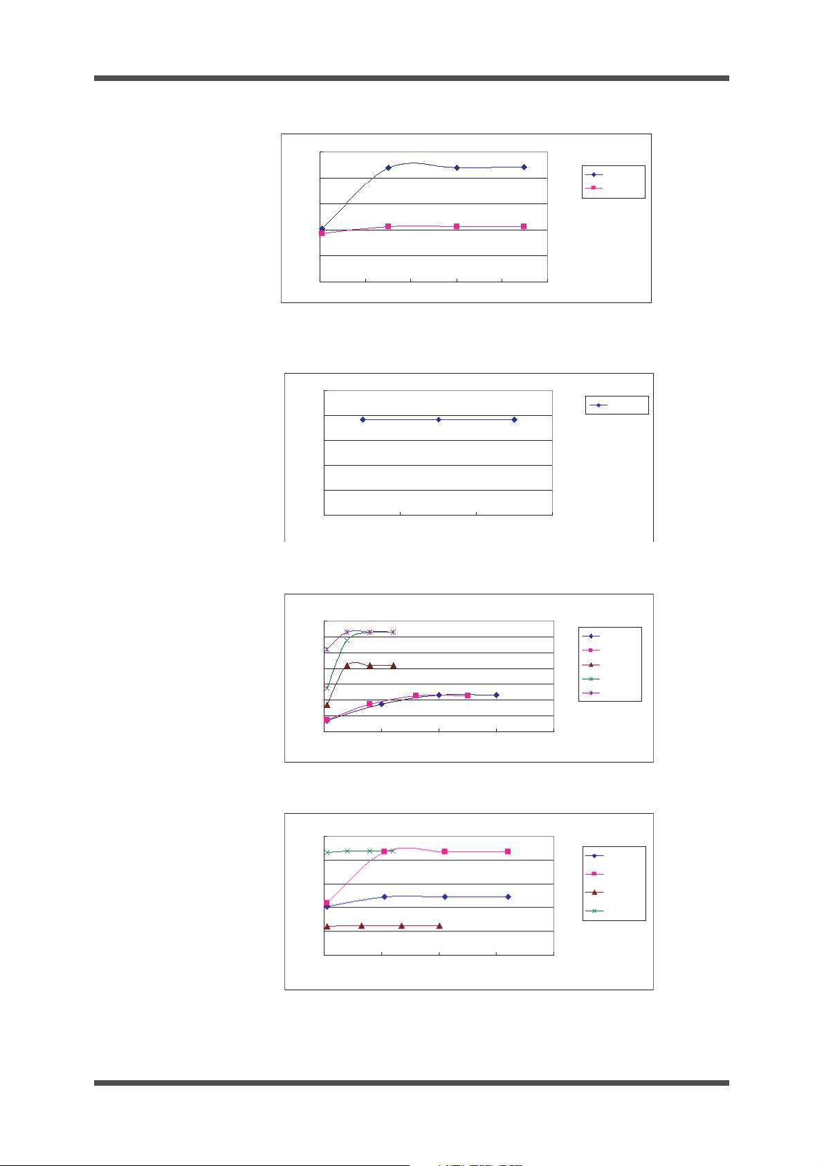
• Saline system
Pure
Soft 1, Soft 2
140
120
100
80
60
40
20
0
0 500 1000 1500 2000 2500
Load resistance ( )
Power (W)
Bipolar: Maximum setting
Cutting Mode: 2 options (Pure, Blend)
Coagulation Mode: 2 options (Coag 1, Coag 2)
2-1-3 Basic frequencies
350 kHz, 1 MHz (when using Spray)
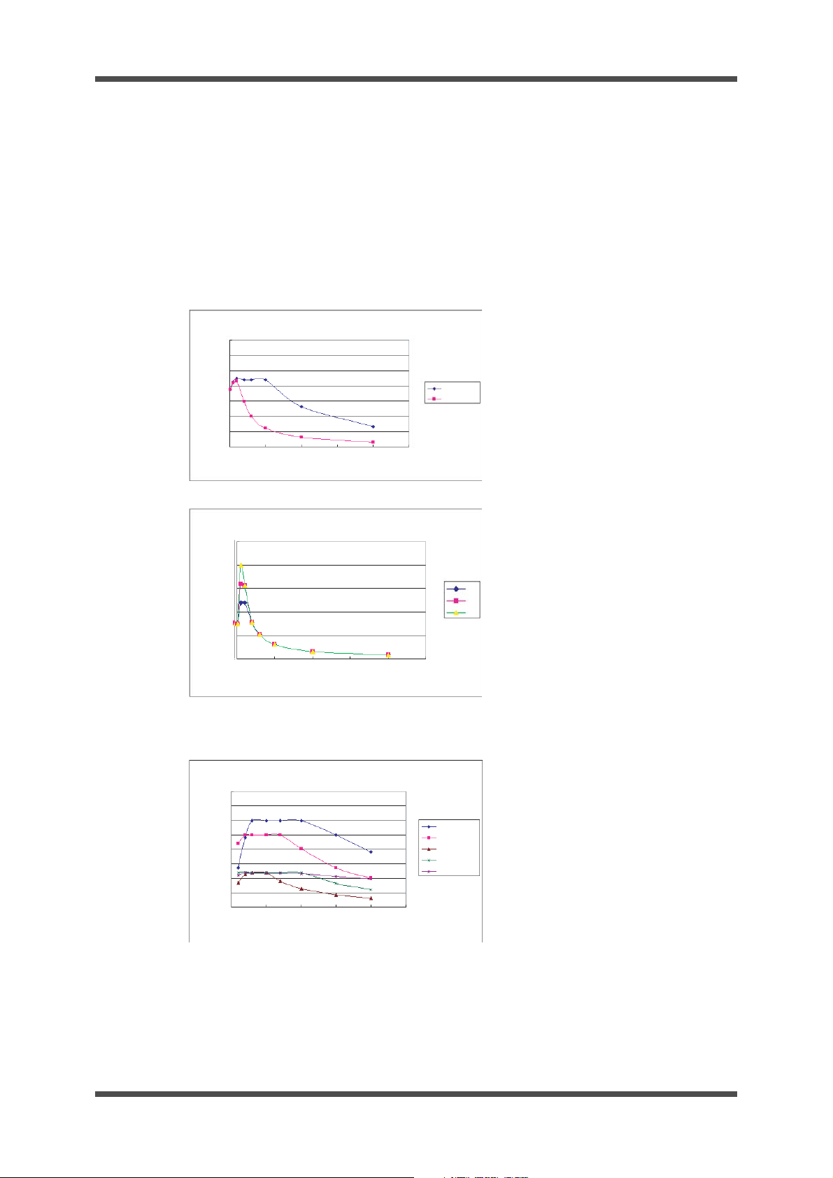
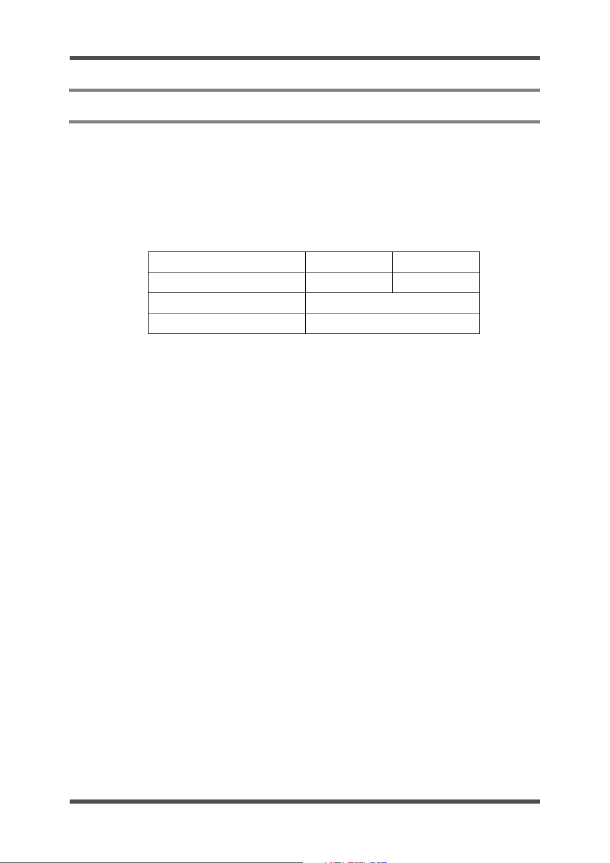
2-1-4 Output characteristics
• Bipolar system
UES-40
250
200
150
100
Power (W)
50
0
0
Bipolar: Maximum setting (Hard)
500 1000 1500 2000 2500
• Monopolar system
400
350
300
250
200
Power (W)
150
100
50
0
0 500 1000
Monopolar: Maximum setting
Load resistance ( )
1500
Load resistance ( )
2000 2500
L1
L2
L3
Pure/Urology
Blend
Coag 1
Coag 2
Spray
ISSUE4 1-3 Product Specification
Page 10
UES-40
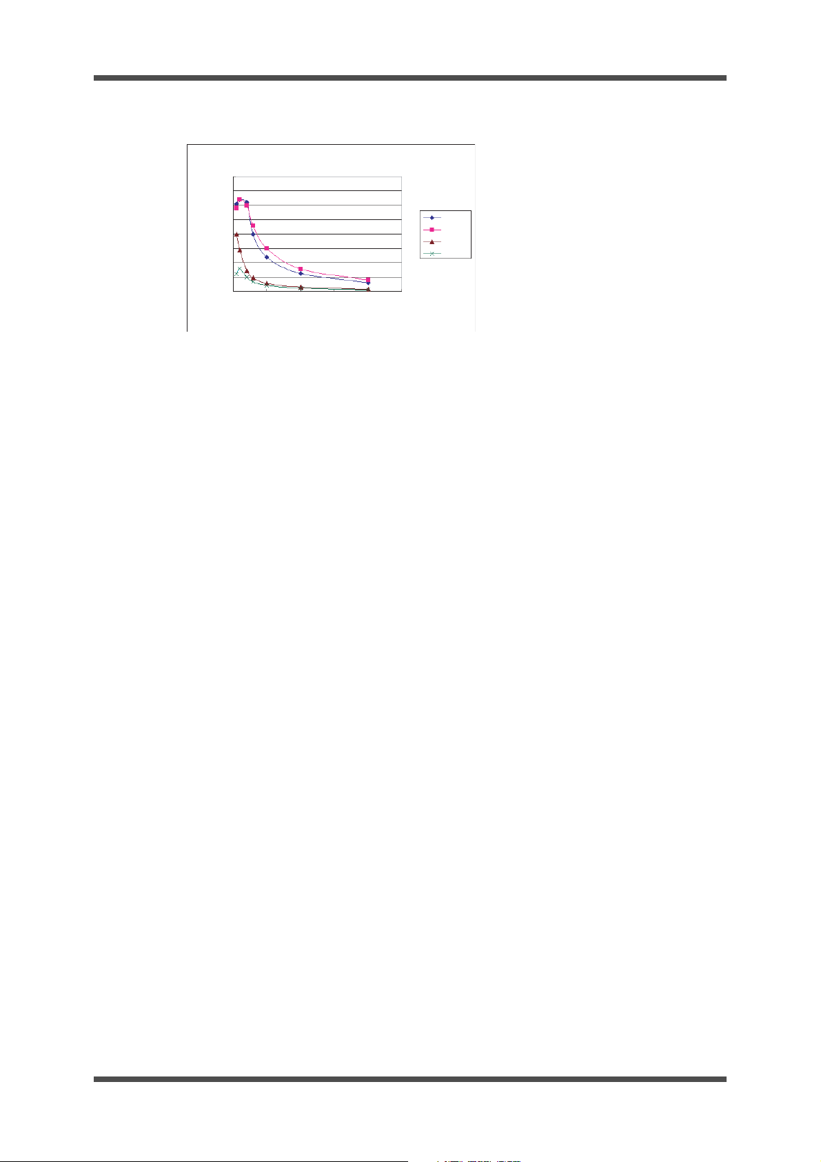
0 500 1000
1500
2000 2500
400
350
300
250
200
150
100
0
50
Pure
Blend
Coag 1
Coag 2
Saline output: Maximum setting
Load resistance ( )
Power (W)
• Saline system
2-1-5 Maximum values
• Bipolar system
Cut: 90 W; Soft 1: 90 W; Soft 2: 90 W; Hard: L3
• Monopolar system
Pure: 300 W; Blend: 250 W; Uro: 300 W; Coag 1: 120 W; Coag 2: 120 W;
Spray: 120 W
• Saline system
Pure: 320 W; Blend: 320 W; Coag 1: 200 W; Coag 2: 80 W
2-1-6 Adjustment increments
• Bipolar system
0 to 20 W: 1-W increments; 20 W to 30 W: 2-W increments; 30 W and over: 5-W increments
(Hard is adjustable in 1-level increments.)
• Monopolar system
5-W increments
• Saline system
5-W increments
2-1-7 Control switches
l Foot switch for UES-40 (MAJ-1258)
Controls the high-frequency output of monopolar and bipolar instruments (ON/OFF)
l Bipolar foot switch for UES-40 (MAJ-1259)
Controls the high-frequency output of bipolar instruments (ON/OFF)
l Handpiece output switch
Controls the high-frequency output of the handpiece (ON/OFF)
Product Specification 1-4 ISSUE4
Page 11
2-1-8 Output terminals
• Bipolar system
Bipolar cord port 2 ports
• Monopolar system
Active port 1 port
Handpiece port 2 ports
• Saline system
Dedicated cord port 1 port
Different control systems are available, depending on the output terminal. The output terminals and their corresponding controls are listed below.
UES-40
System Output terminal
Bipolar 1 port Coag, Cut
Bipolar
Bipolar 2 port Coag only
Saline Saline port Coag, Cut MAJ-1258
Handpiece 1 port Coag, Cut
Monopolar
Active port
Handpiece 2 port Coag, Cut Handpiece
Output
option
Coag, Cut MAJ-1258
Control system Remarks
Foot switch for UES-40
(MAJ-1258)
Bipolar foot switch for
UES-40 (MAJ-1259)
MAJ-1258
handpiece
2-1-9 Recommended timing
Output (ON) timing: within 10 seconds; output stop (OFF): 30 seconds or more
Bipolar output can be
selected using the
switch select switch
The saline port detects the
saline cable to be connected
and the output terminal is
automatically selected.
Monopolar output can be
selected using the Footswitch select switch (except
during control using the
handpiece)
Foot.
2-2 Safety functions
2-2-1 Patient-plate monitor (for monopolar systems only)
Detects connection problems or disconnection of the single type patient plate, as well as
loosening of split type patient plates. If problems are detected, the following operations are
performed.
• Warning indicator is lit.
• Error code is displayed on output indicator.
• Audible warning is issued.
• High-frequency output is stopped.
ISSUE4 1-5 Product Specification
Page 12

UES-40
2-2-2 High-frequency-output monitor
Detects whether the output value is correct for the output setting value. If problems are
detected, the following operations are performed.
• Error code is displayed on output indicator.
• Audible warning is issued.
• High-frequency output is stopped.
2-2-3 Output timing monitor (for monopolar or saline systems only)
Detects the high-frequency output timing. If output continues for more than 60 seconds, the
following operations are performed.
• Error code is displayed on output indicator.
• Audible warning is issued.
• High-frequency output is stopped.
2-2-4 Self-check monitor
Verifies the correct operation of all safety functions. If problems are detected, the following
operations are performed.
• Error code is displayed on output indicator.
• Audible warning is issued.
• Various settings are disabled.
• High-frequency output is stopped.
2-2-5 Control switch monitor
Detects short-circuits of each switch (foot switch and handpiece). If problems are detected,
the following operations are performed.
• Error code is displayed on output indicator.
• Audible warning is issued.
• Various settings are disabled.
• High-frequency output is stopped.
2-3 Additional features
2-3-1 Preset function
Use of the preset function enables the most-recently used output setting, as well as up to
five configurations of preset user settings, to be stored for future use.
2-3-2 CQM function
When split type patient plates are attached, the CQM indicator lights up when there is a
good connection with the patient.
Product Specification 1-6 ISSUE4
Page 13
2-4 Safety
2-4-1 Medical electrical-equipment classifications
l Protection against electrical shock
Class-I equipment (three-prong plug for power supply)
l Level of electrical-shock protection
CF-type (low-frequency leakage current of 10µþA or less)
l Level of explosion protection
Never use the UES-40 where flammable vapors occur.
l Others
Defibrillator protection
2-5 Laws, regulations, and standards
UES-40
Region / country Applicable laws and regulations / external standards
EU/EFTA
U.S. UL mark
Other areas None
2-6 Others
l Dimensions
350 mm (W) ¥ 400 mm (D) ¥ 150 mm (H)
l Weight
12 kg
MDD
Classification: IIb
CE marking: CE0197
ISSUE4 1-7 Product Specification
Page 14
UES-40
3. Operating Requirements
(1) The operating conditions must be as follows.
Ambient temperature: 10°C to 40°C
Relative humidity: 30% to 85%
Atmospheric pressure: 700 hPa to 1060 hPa
Never use the UES-40 where flammable vapors occur.
(2) The power requirements are as follows.
Rated input voltage 120 V 220 V
Rated input current 12A 6A
Frequency 50/60 Hz
Permissible voltage fluctuation ±10%
(3) Do not use in combination with products not designated by Olympus.
(4) Before using the UES-40 for the treatment of patient s weari ng pacemakers, consult the
pacemaker manufacturer.
(5) Do not attach the patient plate for use near metallic implants.
(6) Do not wind UES-40 cords into loops or allow them to touch the patient or metall ic p art s
of the surgical table.
(7) Do not bundle UES-40 cords with cords of other medical equipment during use.
(8) Keep the UES-40 and its cords adequately separated from other medical equipment
and cords.
(9) If non-CF products are used in combination with the UES-40, do not use directly on the
heart.
(10) To ensure electrical safety, use of the following electronic medical equipment in combi-
nation with the UES-40 is prohibited:
a) Equipment not yet proven safe when used with the UES-40
b) Equipment not yet proven safe due to certain aspects of operation (such as the
leakage current)
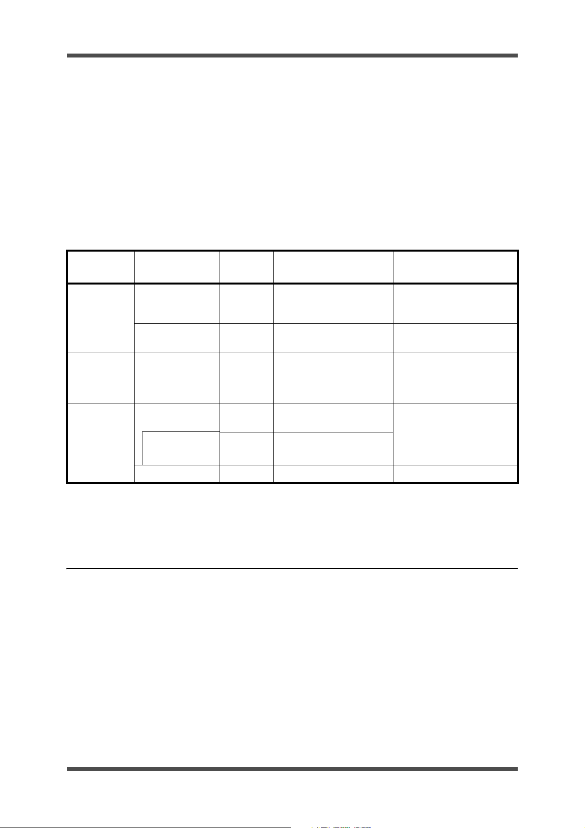
(11) If the UES-40 is used in combination with endoscopic instruments for which the rated
voltage is listed in each instrument user manual, compare the open outpu t-volt age char-
acteristics of the instruments with those of the UES-40 and adjust the output within the
USE-40’s rated voltage values. Refer to Fig. 1-1 to 1-4 for the open voltage characteris-
tics. If the user’s manuals for these instruments do not list the rated voltage, set the out-
put low initially and then gradually increase the output level.
Product Specification 1-8 ISSUE4
Page 15
UES-40
L1 L2 L3
Hard
Bipolar: Hard
Maximum output voltage (Vp)
Output setting (W)
250
200
100
50
0
150
3500
3000
2500
2000
1500
1000
500
0
0 100 200 300 400
Pure/Urology
Blend
Coag 1
Coag 2
Spray
Monopolar
Maximum output voltage (Vp)
Output setting (W)
800
600
400
0
200
0 100 200 300 400
Pure/Urology
Blend
Coag 1
Coag 2
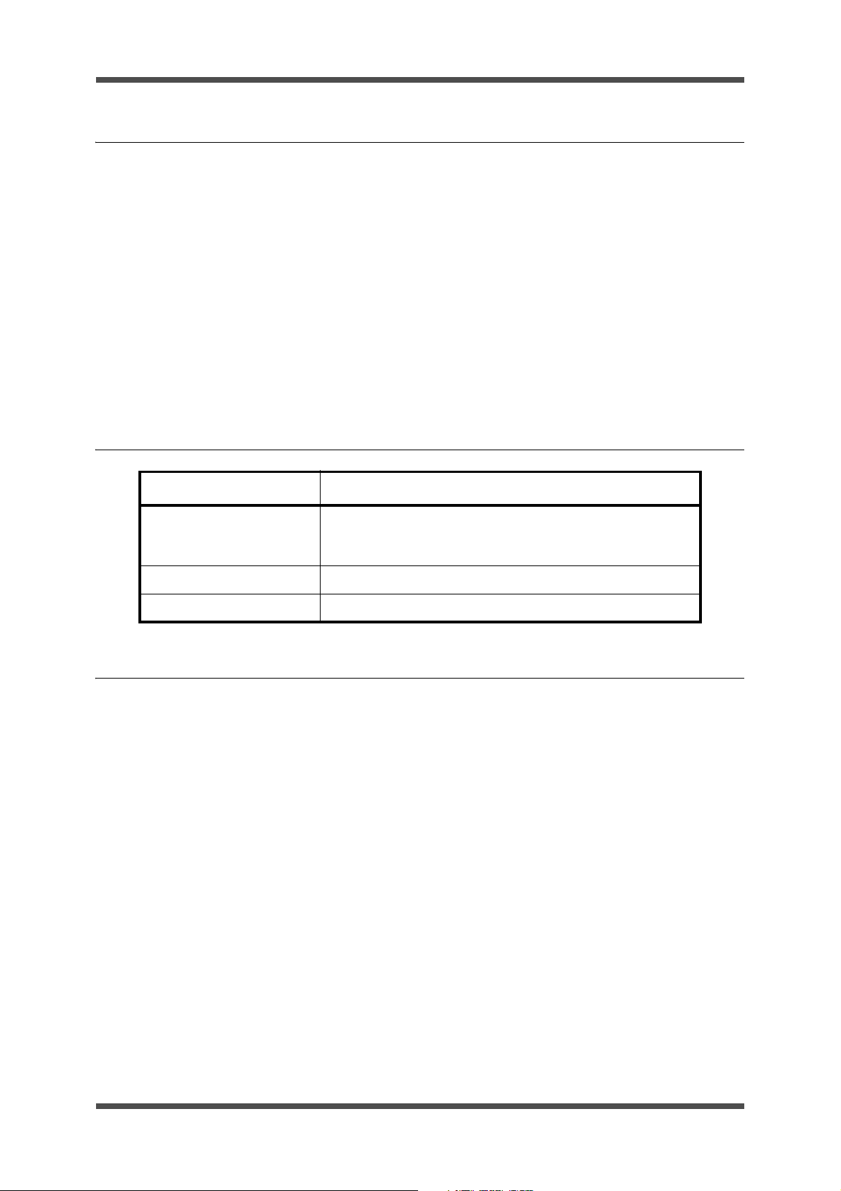
Maximum output voltage (Vp)
Output setting (W)
1000
Saline
500
400
300
200
100
Maximum output voltage (Vp)
0
0
Bipolar: Cut, Soft 1, Soft 2
20 40 60 80 100
Output setting (W)
Cut
Soft1, Soft2
Figure 1-1 Open voltage characteristics (Bipolar: Pure, Soft 1, Soft 2)
Figure 1-2 Open voltage characteristics (Bipolar: Hard)
Figure 1-3 Open voltage characteristics (Monopolar)
ISSUE4 1-9 Product Specification
Figure 1-4 Open voltage characteristics (Saline)
Page 16
UES-40
WW W W
BIPOLAR
CUT
PRESET
MEMORY
WARNING
COM
POWER
BIPOLAR1 HAND PIECE1 HAND PIECE2
PATIENT
F
BIPOLAR2
SOFT1 SOFT2 HARD
SALINE
SALINE PURE
COAG.1 COAG.2
BLEND URO SPRAY
SELECT
COAG
FOOT
SWITCH
SELECT
CUT COAG
SALINE MONOPOLAR
(1) Memory switch
(16) Power switch
(15) Bipolar port 1
(14) Bipolar port 2
(12) Active port
(11) Hand piece
port 1
(9) Patient plate port
(10) Hand piece port 2
(13) Saline port
(2) Select switch
(3) Output control
switch
(4) Bipolar coagulation mode
select switch
(7) Monopolar/saline cut mode select switch
(8) Monopolar/saline coagulation
mode select switch
(5) Saline switch
(6) Foot switch
select switch
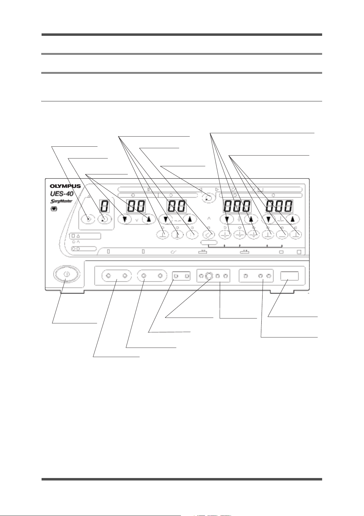
4. Name and Function of Each Part
4-1 Front panel (for 120 V and 220 V)
4-1-1 Switches and ports
(1) Memory switch
This switch is used to store output settings and modes that have been previously set.
(2) Select switch
This switch is used to recall stored output settings and modes.
(3) Output control switches
To increase the displayed setting value, press s. To decrease it, press t.
(4) Bipolar coagulation mode select switches
These switches are used to select bipolar coagulation modes.
(5) Saline switch
This switch is used to select the saline mode.
Product Specification 1-10 ISSUE4
Page 17

(6) Foot-switch select switch
This switch is used to switch between the saline/monopolar mode and the bipolar output mode.
(7) Monopolar/saline cut mode select switches
These switches are used to select the monopolar and saline cut mode
(8) Monopolar/saline coagulation mode select switches
These switches are used to select the monopolar and saline coagulation mode.
(9) Patient-plate port
This port is used for connection of the patient-plate plug.
(10) Handpiece port 2
This port is used for connection of a monopolar handpiece plug.
(11) Handpiece port 1
This port is used for connection of a monopolar handpiece plug.
(12) Active port
This port is used for the connection of the active electrode of the Active cord.
(13) Saline port
This port is used for connection of the saline code.
(14) Bipolar port 2
This port is used for connection of bipolar electrodes.
UES-40
(15) Bipolar port 1
This port is used for connection of bipolar electrodes.
(16) Power switch
For turning the power on. When the power is turned on, the power switch indicator lights up.
ISSUE4 1-11 Product Specification
Page 18
UES-40
WW W W
BIPOLAR
CUT
PRESET
MEMORY
WARNING
COM
POWER
BIPOLAR1 HAND PIECE1 HAND PIECE2
PATIENT
F
BIPOLAR2
SOFT1 SOFT2 HARD
SALINE
SALINE PURE
COAG.1 COAG.2
BLEND URO SPRAY
SELECT
COAG
FOOT
SWITCH
SELECT
CUT COAG
SALINE MONOPOLAR
(18) Preset number indicator
(21) Foot switch setting indicators
(17) Output indicators
(22) Monopolar/saline cut output setting indicator
(19) Bipolar cut output setting indicator
(20) Bipolar coagulation output setting indicator
(30) Warning indicator
(29) CQM indicator
(28) Power switch indicator
(27) Bipolar coagulation mode indicators
(26) Saline mode indicator
(25) Monopolar/saline cut mode indicators
(24) Monopolar/saline coagulation
mode indicators
(23) Monopolar/saline coagulation
output setting indicator
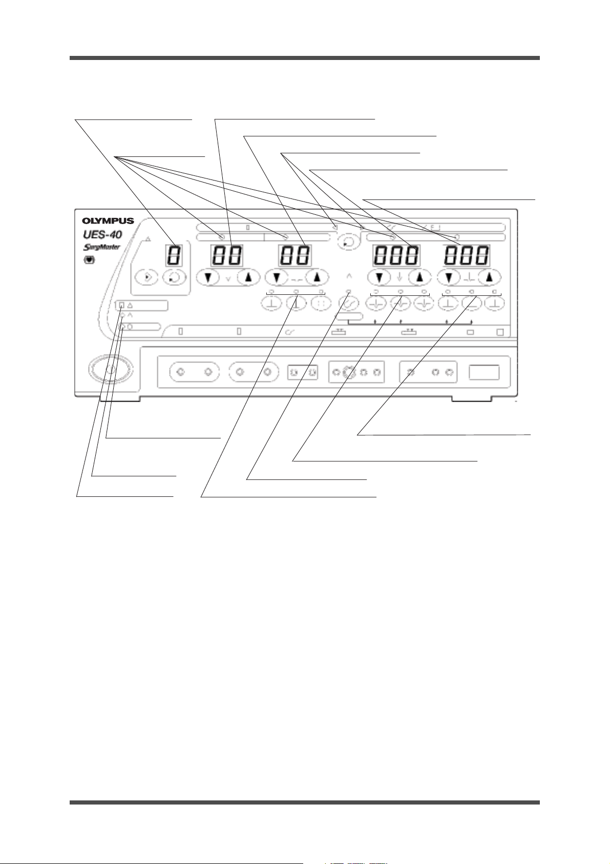
4-1-2 Indicators
(17) Output indicators
During high-frequency output, the indicator corresponding to the selected output mode (Cut or
Coag) lights up.
(18) Preset number indicator
During the use of preset functions, this indicator displays digits from 1 to 5 or P.
(19) Bipolar cut output setting indicator
This indicator displays the value specified using the output control switches.
(20) Bipolar coagulation output setting indicator
This indicator displays the value specified using the output control switches.
(21) Foot-switch setting indicator
This indicator displays the available output from the foot switch for the UES-40 (MAJ-1258).
(22) Monopolar/saline cut output setting indicator
This indicator displays the value specified using the output control switches.
(23) Monopolar/saline coagulation output setting indicator
This indicator displays the value specified using the output control switches.
(24) Monopolar/saline coagulation mode indicators
The lighted indicator corresponds to the coagulation mode selected using the switches.
Product Specification 1-12 ISSUE4
Page 19
(25) Monopolar/saline cut mode indicators
SYSTEM
SN
MAJ-1259
MAJ-1258
12A
AC IN
BREAKERS
Foot Switch
VOLUME
12A
Foot Switch
(7) Potential equalization terminal
(1) System port
(5) Circuit breakers
(2) Volume knob
(3) Foot switch port for MAJ-1258
(4) Foot switch connector for MAJ-1259
(6) AC inlet
The lighted indicator corresponds to the cutting mode selected using the switches.
(26) Saline mode indicator
This indicator lights up when saline mode is selected using the switch.
(27) Bipolar coagulation mode indicators
The lighted indicator corresponds to the coagulation mode selected using the switches.
(28) Power switch indicator
This indicator shows that the power is on after the power switch is activated.
(29) CQM indicator
When split type patient plates are attached, the CQM indicator lights up when there is a good
connection with the patient.
(30) Warning indicator
This indicator lights up if equipment problems occur.
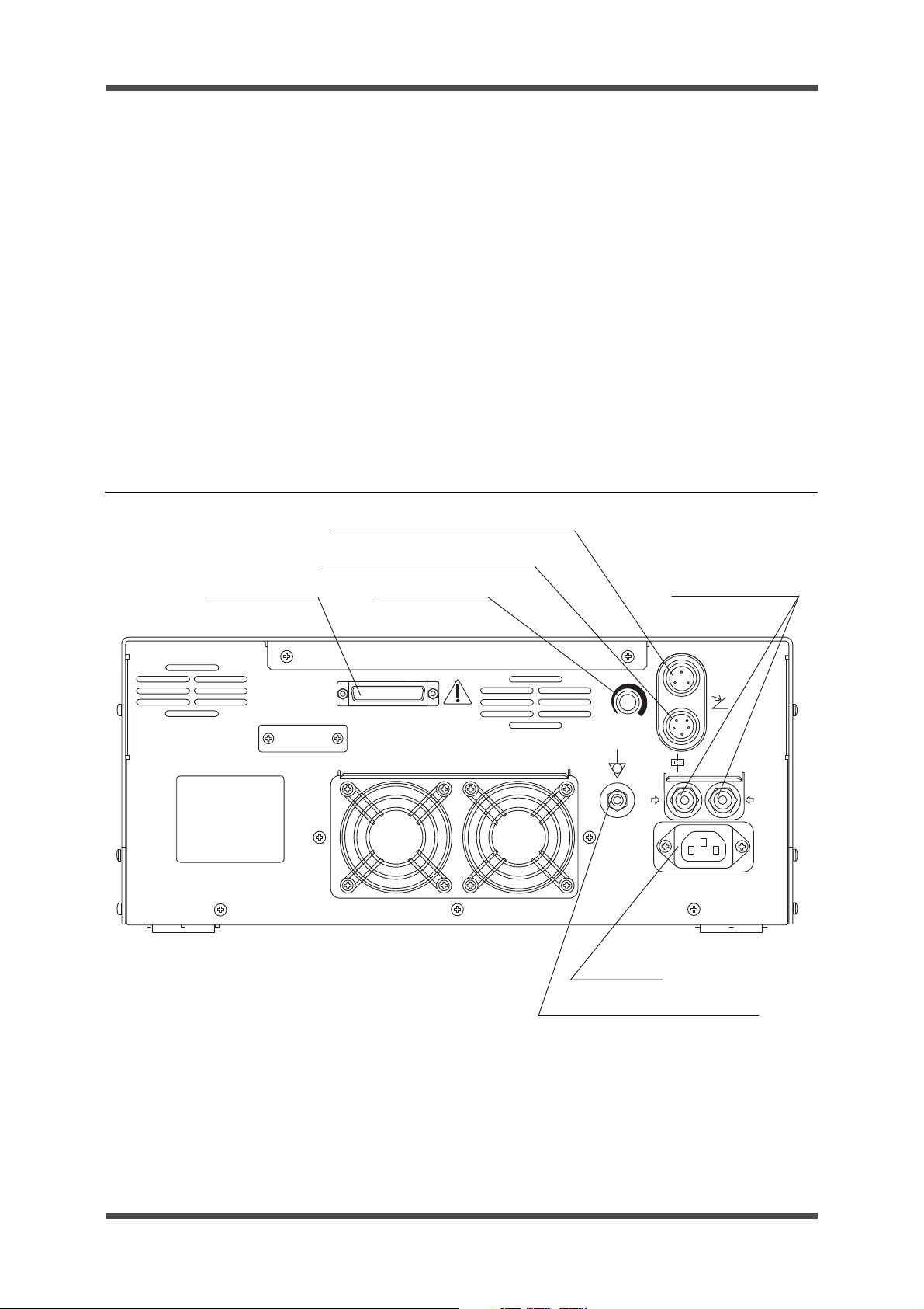
4-2 Rear panel
UES-40
(1) System port
This system port is for connecting products to expand the functionality of the unit. Connect only
Olympus products.
(2) Vo lume knob
This knob is for adjustment of the sound output.
ISSUE4 1-13 Product Specification
Page 20
UES-40
As viewed from the connection side
As viewed from the connection side
(3) Foot switch port for MAJ-1258
This port is for connecting the standard accessory foot switch for UES-40.
(4) Foot switch port for MAJ-1259
This port is for connecting an optional bipolar foot switch for UES-40.
(5) Circuit breakers
These breakers are used in the event of mechanical problems to prevent electrical surges
within the UES-40.
(6) AC inlet
This inlet is for connecting the power cord.
(7) Potential-equalization terminal
This terminal is connected for potential equalization.
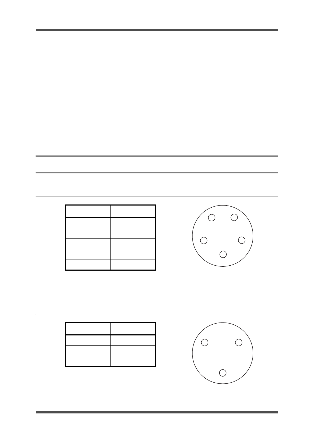
5. Ports
5-1 Foot switch port for MAJ-1258
Pin No. Signal
AFS1CUT1
B TS1COAG1
CFS1PA1
DGND
EFS/MODE
5-2 Bipoler foot switch port for MAJ-1259
Pin No. Signal
A FS3COAG1
BGND
A
B
A
E
D
C
C
CNC
Product Specification 1-14 ISSUE4
B
Page 21

5-3 System port
As viewed from the connection side
Pin No. Signal Pin No. Signal
1NC14SG1
2TxD115NC
3RxD116 NC
4RTS117 NC
5CTS118 NC
6DSR119 NC
7 SG1 20 DTR1
8NC21NC
9NC22NC
10 NC 23 NC
UES-40
11 NC 24 NC
12 NC 25 NC
13 SMKEVAC1
13 12 11 10 9 8 7 6 5 4 3 2 1
25 24 23 22 21 20 19 18 17 16 15 14
ISSUE4 1-15 Product Specification
Page 22

UES-40
A adapter 2
(MAJ-619)
A adapter 3
(MAJ-620)
Interactive cable
(MAJ-877)
High flow insufflation unit (UHI-3)
High flow insufflation unit (UHI-2)
A cord
(A02915A (MAJ-860))
(A02916A (MAJ-861)*)
(A8406 (MH-969)**)
(MA-255**)
UES-40
Disposable
P-cord
(MAJ-814)
High frequency accessory
Bipolar foot switch for
UES-40 (MAJ-1259)
Videoscope
without the S-cord
connector mount
Fiberscope without the
S-cord connector mount
Foot switch
(MAJ-1258)
Some products may not be available in some regions. Please contact the nearest Olympus office for details
Specifications, design and accessories are subject to change without any notice or obligation on the part of the
manufacturer.
6. System Diagram
6-1 Endoscopic Treatment with UES-40 - System Diagram
l 120 V specification
Product Specification 1-16 ISSUE4
Page 23

l 220 V specification
A adapter 2
(MAJ-619)
A adapter 3
(MAJ-620)
Interactive cable
(MAJ-877)
High flow insufflation unit (UHI-3)
High flow insufflation unit (UHI-2)
A cord
(A02915A (MAJ-860))
(A02916A (MAJ-861)*)
(A8406 (MH-969)**)
(MA-255**)
UES-40
Disposable
P-cord
(MAJ-814)
P-plate
(MAJ-897)
High frequency accessory
Bipolar foot switch for
UES-40 (MAJ-1259)
Videoscope
without the S-cord
connector mount
Fiberscope without the
S-cord connector mount
Foot switch
(MAJ-1258)
UES-40
ISSUE4 1-17 Product Specification
Page 24

Working elements
(A2749), (A2750)
(A2751), (A2752)
(A2753), (A2754)
(A2755), (A2757)
(A3752), (A4512)
Sheath
Sheath
Trocar tube
Laparoscopic instrument
(4 mm connector)
4ψ3 mm adapter
(A0101)
3ψ4 mm adapter
(A0100)
Laparoscopic instrument
(3 mm connector)
Bipolar forceps
Bipolar forceps
(A5380), (A5382)
(A5384), (A5386)
(A5388), (A5390)
(A5392), (A5394)
Bipolar forceps
(O5119)
Saline electrodes
(WA22301D), (WA22302D)
(WA22305D), (WA22306D)
(WA22331D), (WA22332D)
(WA22351A), (WA22351C)
(WA22355A), (WA22355C)
Electrode
Saline working elements
(WA22060B)
(WA22061B)
Working elements
(A22060A), (A22061A)
(A20063A)
Working elements
(A2760), (A2761)
Resectoscope for saline
(and other cystourethroscopes)
A
B
C
D
E
F
G
H
I
J
UES-40
6-2 Electrosurgical Treatment with UES-40 - System Diagram
l 120 V specification
Product Specification 1-18 ISSUE4
Page 25

A adapter (MAJ-1) is not available in some countries.
**: A adapter 2 (MAJ-619) is required when the A-Cord marked (**) is used.
*: A adapter 3 (MAJ-620) is required when the A-Cord marked (*) is used.
A
UES-40
B
C
D
A cord
(A0139.1**)
(A0139.2**)
(A0336.1)
E
F
(WA00013A)
A cord
(A00010A**)
(A00011A*)
(A00012A)
A cord
(A0391**)
(A0392*)
(A0393)
A cord
(3 mm type)
(A0130.1**), (A0130.2**)
(A0335.1)
A adapter 2
(MAJ-619)
A adapter 3
(MAJ-620)
Foot switch
(MAJ-1259)
Foot switch
(MAJ-1258)
UES-40
G
A cord
(4 mm type)
(A0355**), (A0357*), (A0358)
(A00506A)
Hand piece
H
Bipolar cord
(A5121.1)
I
Bipolar cord
(A5377)
J
Bipolar cord
Disposable
P-plate
ISSUE4 1-19 Product Specification
Page 26

Working elements
(A2749), (A2750)
(A2751), (A2752)
(A2753), (A2754)
(A2755), (A2757)
(A3752), (A4512)
Sheath
Sheath
Trocar tube
Laparoscopic instrument
(4 mm connector)
4ψ3 mm adapter
(A0101)
3ψ4 mm adapter
(A0100)
Laparoscopic instrument
(3 mm connector)
Bipolar forceps
Bipolar forceps
(A5380), (A5382)
(A5384), (A5386)
(A5388), (A5390)
(A5392), (A5394)
Bipolar forceps
(O5119)
Saline electrodes
(WA22200D)
(WA22232D)
(WA22208D)
(WA22209D)
(WA22233D)
Electrode
Saline working elements
(WA22060B)
(WA22061B)
Working elements
(A22060A), (A22061A)
(A20063A)
Working elements
(A2760), (A2761)
Resectoscope for saline
(and other cystourethroscopes)
K
L
M
N
O
P
Q
R
S
T
UES-40
l 220 V specification
Product Specification 1-20 ISSUE4
Page 27

A adapter 2
(MAJ-619)
A cord
(A00010A**)
(A00011A*)
(A00012A)
(WA00013A)
A cord
(3 mm type)
(A0130.1**), (A0130.2**)
(A0335.1)
A cord
(A0139.1**)
(A0139.2**)
(A0336.1)
A cord
(A0391**)
(A0392*)
(A0393)
A cord
(4 mm type)
(A0355**), (A0357*), (A0358)
(A00506A)
Bipolar cord
(A5121.1)
Bipolar cord
(A5377)
Bipolar cord
A adapter 3
(MAJ-620)
UES-40
Hand piece
P-cord
(MAJ-814)
P-plate
(MAJ-897)
Foot switch
(MAJ-1259)
Foot switch
(MAJ-1258)
A adapter (MAJ-1) is not available in some countries.
**: A adapter 2 (MAJ-619) is required when the A-Cord marked (**) is used.
*: A adapter 3 (MAJ-620) is required when the A-Cord marked (*) is used.
K
L
M
N
O
P
Q
R
S
T
UES-40
ISSUE4 1-21 Product Specification
Page 28

Page 29

Chapter 2: Troubleshooting
Chapter 2:Troubleshooting
1 Troubleshooting.......................................................2-2
2 Error Codes .............................................................2-7
ISSUE4 2-1 Troubleshooting
Page 30

UES-40
UPHF40SS00U
(monitor board)
UPHF40CR00U
(control board)
UPHF40OT00U
(oscillation board)
CONVERTER
UPHF40EX00U
(relay board)
1. Troubleshooting
Configuration of the main unit
Troubleshooting 2-2 ISSUE4
Page 31

ISSUE4 2-3 Troubleshooting
*
1
Problem
Power-on
problem
No response
even when the
output
switches
pressed
*1 The numbers indicate the relative likelihood that this is the affected unit. These numbered units may be damaged.
*2 Foot-switch cutting or coagulation pedal and handpiece output switch
Converter fan unresponsive — — — — — 1 Converter – Power switch Power switch —
Power-switch LED remains unlit. — — — 3 2 1 Converter – Oscillation board (J2) Power switch —
No startup sound — 2 — 1 — 3 Oscillation board (J3) – Monitor board (J5) — —
All panel lights remain unlit. — — — 1 2 — Control board (J2) – Panel sheet — —
All panel lights remain lit. — — — 1 2 — — — —
All output switches
including the handpiece and foot
2
switch are unre-
are
*
sponsive.
Handpiece switch
unresponsive (but
foot switch works)
Foot switch unresponsive (but
handpiece switch
works)
Switch unresponsive when using
handpiece connector 1
Switch unresponsive when using
handpiece connector 2
Foot switch (MAJ-
1258) unresponsive
Bipolar foot switch
(MAJ-1259) unresponsive
No sound — 2 — 1 — — — — —
LEDs remain unlit. — — — 1 2 — — — —
No sound, LEDs
remain unlit.
No sound — 1 — 2 — — — — —
LEDs remain unlit. — — — 1 2 — — — —
No sound, LEDs
remain unlit.
No sound — 1 — 2 — — — — —
LEDs remain unlit. — — — 1 2 — — — —
No sound, LEDs
remain unlit.
No sound — 1 — 2 — — — — —
LEDs remain unlit. — — — 1 2 — — — —
No sound, LEDs
remain unlit.
No sound — 1 — 2 — — — — —
LEDs remain unlit. — — — 1 2 — — — —
No sound, LEDs
remain unlit.
No sound — 1 — 2 — — — — —
LEDs remain unlit. — — — 1 2 — — — —
No sound, LEDs
remain unlit.
No sound — 1 — 2 — — — — —
LEDs remain unlit. — — — 1 2 — — — —
No sound, LEDs
remain unlit.
Oscillation
Monitor
Relay
Control
Panel
board
board
board
board
—2—1—— — — —
—132—— — — —
—1—2—— — — —
— 1 3 2 — — — Front port
— 1 3 2 — — — Front port
— 1 3 2 — — Monitor board (J1) – Foot switch (MAJ-1258) Foot switch
— 1 3 2 — — Monitor board (J1) – Foot switch (MAJ-1259) Foot switch
Converter Harnesses Other Other than main unit
sheet
Parts That Might Have Caused the Problem
Oscillation board (J4) – Control board (J5)
Control board (J2) – Panel sheet
Monitor board (J2) – Speaker
Monitor board (J16) – Control board (J1)
part
part
(MAJ-1258)
port part
(MAJ-1259)
port part
Handpiece switch damage
Handpiece switch damage
Foot-switch
damage
Foot-switch
damage
(Continued next page)
ëÊ2èÕ Troubleshooting
1-1 Troubleshooting list
UES-40
Page 32

Troubleshooting 2-4 ISSUE4
Problem
There is a
response when
the output
switch is
pressed, but it
cannot be
treated.
Cannot be set upPanel-switch prob-
No output
Low output
High output
All normal
lem
Active cord
(for saline) is
not detected.
*
1
Oscillation
7-segment LED
problem (cannot
display correctly)
Switch unresponsive
LEDs remain unlit. — — — 2 1 — Control board (J2) – Panel sheet — —
Pressing the
switch once gives
a prolonged
response
No sound — 1 — 2 — —
Even with the cord
attached, saline
mode is unavailable.
Cord is not
attached, but unit
is in saline mode.
Removing the cord
does not restore
the mode.
Monitor
Relay
Control
Panel
board
board
board
board
1243—5
2143—5
2143—5
—————— — —
— — — 2 1 — Control board (J2) – Panel sheet — —
— — — 2 1 — Control board (J2) – Panel shee — —
— — — 2 1 — Control board (J2) – Panel sheet — —
—132——
—132—— —
—132—— —
Converter Harnesses Other Other than main unit
sheet
Parts That Might Have Caused the Problem
Converter – Oscillation board (J1)
Monitor board (J3) – Oscillation board (J7)
Monitor board (J3) – Oscillation board (J3)
Oscillation board (J4) – Control board (J5)
Monitor board (J7) – Relay board (J2)
Monitor board (J5) – Relay board (J1)
Monitor board (J16) – Control board (J1)
Converter – Oscillation board (J5)
Monitor board (J16) – Control board (J1)
Oscillation board (J4) – Control board (J5)
Monitor board (J16) – Control board (J1)
Monitor board (J2) – Speaker
Monitor board (J16) – Control board (J1)
Monitor board (J5) – Relay board (J1)
Monitor board (J16) – Control board (J1)
Front port
part
Front port
part
——
• Active cord disconnected
• Incorrect use
Speaker —
Front port
part
Front port
part
Front port
part
Active cord (for saline) connector is
defined.
UES-40
—
—Oscillation board (J4) – Control board (J5)
—
—
(Continued next page)
Page 33

ISSUE4 2-5 Troubleshooting
When used with
the UHI, does
not control
smoke and cannot be linked
No communication with
EndoALPHA
Error code displayed
*
1
Problem
Does not function in a ganged manner
Ganged when not switched ON
No communication
Communication interruptions
Patient-plate problem (Coag. 01)
Solution detection problem (Coag. 02)
Output timing problem (Coag. 04)
Output-switch problem (Coag. 08) — 1 3 2 — — — — One of the output switches is broken.
Output-switch ON problem (Coag. 10) — 1 3 2 — — — — One of the output switches is broken.
Short circuit of setting-switch
(Coag. 20)
Oscillation
Monitor
Relay
Control
Panel
board
board
board
board
— — — 1 — — Control board (J6) – System port System port part
— — — 1 — — Control board (J6) – System port System port part
— — — 1 — — Control board (J6) – System port System port part
— — — 1 — — Control board (J6) – System port System port part
4132——
4132——
—231—— —
— — — 2 1 — Control board (J2) – Panel sheet
Converter Harnesses Other Other than main unit
sheet
Parts That Might Have Caused the Problem
Monitor board (J5) – Relay board (J1)
Monitor board (J16) – Control board (J1)
Converter – Oscillation board (J1)
Converter – Oscillation board (J5)
Monitor board (J3) – Oscillation board (J7)
Monitor board (J6) – Oscillation board (J3)
Oscillation board (J4) – Control board (J5)
Monitor board (J7) – Relay board (J2)
Monitor board (J5) – Relay board (J1)
Monitor board (J16) – Control board (J1)
Front connector
part
Front connector
part
Foot switch
(MAJ-1258)
connector part
• Smoke-controlling cable disconnected
• Using an EndoALPHA communication cable
• UHI not ready for smoke control
• UHI main-unit damage
• Use a cable other than the smokecontrol cable or EndoALPHA communication cable
• UHI main-unit damage
• EndoALPHA communication cable
disconnected
• Using smoke-control cable
• UCES damage
• EndoALPHA communication cable
disconnected
• UCES damage
• Patient-plate cord disconnected
• Patient plate coming loose
• Using a liquid other than saline (uromatic or the like)
• Output in air
Monopolar output for more than 60
sec
(Continued next page)
UES-40
Page 34

Troubleshooting 2-6 ISSUE4
(From previous
page)
Error code displayed
Problem
High-frequency current monitor damage (Cut 01)
*
1
Oscillation
Monitor
Relay
Control
Panel
board
board
board
board
—132——
Converter Harnesses Other Other than main unit
sheet
Parts That Might Have Caused the Problem
Monitor board (J7) – Relay board (J2)
Monitor board (J16) – Control board (J1)
Used where the high-frequency current is prone to leakage. (Touching
metal parts of patient’s bed or objects
such as external devices that have
fallen to the ground; used simultaneously with high-frequency grounded
—
electric scalpels [semi-floating], etc.)
UES-40
High-frequency voltage-monitor damage (Cut 02)
2143—5
Waveform-circuit damage (Cut 04) — — — 1 — — — — —
Converter (Power-supply) 1 damage
(Cut 08)
Converter (Power-supply) 2 damage
(Cut 10)
Converter (Power-supply) 3 damage
(Cut 20)
Patient-plate-circuit damage (Cut 40)
3——1—2
3——1—2
3——1—2
—132——
Converter – Oscillation board (J1)
Converter – Oscillation board (J5)
Monitor board (J3) – Oscillation board (J7)
Monitor board (J6) – Oscillation board (J3)
Oscillation board (J4) – Control board (J5)
Monitor board (J7) – Relay board (J2)
Monitor board (J16) – Control board (J1)
Oscillation board (J4) – Control board (J5)
Oscillation board (J5) – Converter
Oscillation board (J4) – Control board (J5)
Oscillation board (J5) – Converter
Oscillation board (J4) – Control board (J5)
Monitor board (J5) – Relay board (J1)
Monitor board (J16) – Control board (J1)
——
——
——
——
——
Page 35

ëÊ2èÕ Troubleshooting
2-1 Error-code list
Display location and error codes
UES-40
2. Error Codes
Monopolar cut
output-setting
indicator
— 01 Patient-plate problem
—02
—04
—08
—10
—20
01 —
02 —
04 —
08 —
10 —
20 —
40 —
Monopolar
coagulation output-
setting indicator
Error Identification Remarks
Solution detection
problem
Output timing problem
Output-switch problem
Output-switch ON
problem
Short-circuit of
setting switch
High-frequency
current-monitor damage
High-frequency voltage-monitor damage
Waveform-circuit
damage
Converter (power
supply)-1 damage
Converter (power
supply)-2 damage
Converter (power
supply)-3 damage
Patient-plate circuit
damage
• Patient-plate cord is disconnected.
• Improper patient-plate connection
•
Patient plate
• Output occurred without the use
of saline
• Output occurred when the electrode was not immersed in sa line .
• Active cord (for saline) is disconnected.
• Active cord (for saline) is broken.
Output for more than 60 sec
(Only during monopolar or saline
mode)
• Output level set to 0 W
• Output switch damaged
• Power was supplied while the
output switch was pressed.
Multiple switches of the foot switch
or handpiece were simultaneously
pressed.
• Power was supplied while the
front-panel switches were
pressed.
• A front-panel switch is damaged.
Overcurrent signal (converter)
Overvoltage signal (converter)
Temperature problem signal (con-
verter)
is disconnected.
ISSUE4 2-7 Troubleshooting
Page 36

Page 37

Chapter 3: Disassembly and Reassembly Procedure
Chapter 3:Disassembly and Reassem-
bly Procedure
1 Precautions for disassembly and reassembly..........3-2
2 Disassembly procedure ........................................... 3-3
3 Reassembly procedure..........................................3-16
ISSUE4 3-1 Disassembly and Reassembly Procedure
Page 38

UES-40
1. Precautions for disassembly and reassembly
(1) Keep all components safe, since you will need to reattach them at their original positions and reroute
the cables as originally routed.
(2) Exercise extreme caution to prevent possible injuries during disassembly.
Be especially careful to avoid injuring yourself on the sharp edges of metal parts.
(3) Remove the cable housing carefully. Never detach cables by pulling on them.
(4) To ensure electrical safety in accordance with the governing electrical standards, attach the following
in their original configurations when reassembling:
a) Insulators, such as insulating tubes and mylar sheets
b) Cables tied with binder to keep them from touching heat-generating and high-voltage compo-
nents
c) Cover screws with toothed washers to reduce noise radiation
(5) Always use specified components.
The product is comprised of components designed to withstand anticipated vibration, heat, and volt-
age. When replacing any component, make sure that the replacement component has the same
characteristics as the original component.
(6) Be sure to use the specified tightening torque and components of specified dimensions.
(7) Clean the components.
When reusing components, first remove any sealing tape and sealing compound, then clean them.
Note that you must clean the surfaces of any O-rings and packings that will come in contact with
components before use. Failure to do so may result in water leak against moisture or other problems.
(8) Check that all screws and nuts are properly tightened.
Failure to do so will result in water leak or other problems.
Disassembly and Reassembly Procedure 3-2 ISSUE4
Page 39

2-1 Tools
No. N ame Specifications Remarks
1 Box screwdriver 5 mm between opposite sides
2 Box screwdriver 5.5 mm between opposite sides
3 Box screwdriver 8 mm between opposite sides
4 Wrench 19 mm between opposite sides
5 Neji-lock 1401C Red
6 Phillips screwdriver No.1
7 Phillips screwdriver No.2
UES-40
2. Disassembly procedure
ISSUE4 3-3 Disassembly and Reassembly Procedure
Page 40

UES-40
TOP COVER
CBK3x6SA
1 SCREW
HCBK3x6SA
12 SCREWS (6 on the opposite side)
HCBK3x6SA
2 SCREWS
E45F CABLE
J5
UPHF40CR00U
(control board)
UPHF40SS00U
(monitor board)
J5
E23F CABLE
2-2 Disassembly procedure
2-2-1 UES-40 main-unit disassembly
(1) Remove the 15 SCREWS holding the TOP
COVER (HCBK3x6SA: 14 SCREWS;
CBK3x6SA: 1 SCREW) and remove the TOP
COVER.
Phillips screwdriver (No. 2)
Note: During reassembly, make sure no
CABLES are caught under the
COVER.
(2) Detach the E45F CABLE from J5 of
UPHF40CR00U (control board).
(3) Detach the E23F CABLE from J5 of
UPHF40SS00U (monitor board).
Disassembly and Reassembly Procedure 3-4 ISSUE4
Page 41

UES-40
J7
E23 HARNESS
UPHF40SS00U
(monitor board)
FRONT PANEL UNIT
C6N3SZ
3 NUTS
CABLE
FRONT PANEL UNIT
POWER SWITCH
Green tube, black wire
Blue tube, black wire
Green tube, white wire
Blue tube,
white wire
(4) Detach the E23 HARNESS from J7 of
UPHF40SS00U (monitor board).
(5) Remove the 3 NUTS holding the FRONT
PANEL UNIT (C6N3SZ) and detach the
FRONT PANEL UNIT.
Box screwdriver (5.5 mm between opposite sides)
ISSUE4 3-5 Disassembly and Reassembly Procedure
(6) Detach the CABLE from the POWER
SWITCH, and then remove the FRONT
PANEL UNIT.
Note: During reassembly, pay attention to
the following items:
• Fully reinsert the CABLE into the
POWER SWITCH.
• If the binder is removed during disassembly, bind the root of the CABLE
for reassembly.
Page 42

UES-40
UPHF40CR00U
(control board)
J16
E12 HARNESS
E24F CABLE
UPHF40SS00U
(monitor board)
UPHF40OT00U
(oscillation board)
J1
J3
J7
SYSTEM HARNESS
E14F CABLE
UPHF40CR00U
(control board)
UPHF40OT00U
(oscillation board)
J5
J6
J4
UPHF40CR00U (control board)
CCUK3x6SZ
4 SCREWS
(7) Detach the E12 HARNESS from J3 of
UPHF40SS00U (monitor board) and J7 of
UPHF40OT00U (oscillation board).
(8) Detach the E24F CABLE from J1 of
UPHF40CR00U (control board) and J16 of
UPHF40SS00U (monitor board).
(9) Detach the E14F CABLE from J5 of
UPHF40CR00U (control board) and J4 of
UPHF40OT00U (oscillation board).
(10) Detach the SYSTEM HARNESS from J6 of
UPHF40CR00U (control board).
(11) Remove the 4 SCREWS (CCUK3x6SZ) hold-
ing UPHF40CR00U (control board), and
detach UPHF40CR00U (control board).
Phillips screwdriver (No. 2)
Disassembly and Reassembly Procedure 3-6 ISSUE4
Page 43

UES-40
E12 HARNESS 2
UPHF40OT00U (oscillation board)
J6
J3
UPHF40SS00U
(monitor board)
SPEAKER HARNESS
UPHF40SS00U
(monitor board)
J9
J2
VOLUME HARNESS
UPHF40SS00U
(monitor board)
J1
J17
FSW MONO HARNESS
FSW BI HARNESS
(12) Detach the E12 HARNESS 2 from J6 of
UPHF40SS00U (monitor board) and J3 of
UPHF40OT00U (oscillation board).
(13) Detach the VOLUME HARNESS from J9 of
UPHF40SS00U (monitor board), and detach
the SPEAKER HARNESS from J2 of
UPHF40SS00U (monitor board).
ISSUE4 3-7 Disassembly and Reassembly Procedure
(14) Detach the bottom FSW MONO HARNESS
from J1 of UPHF40SS00U (monitor board)
and the top FSW BI HARNESS from J17 of
UPHF40SS00U (monitor board).
Page 44

UES-40
UPHF40SS00U
(monitor board)
4 SPACERS
CCUK3x6SZ
2 SCREWS
J2
CONVERTER
J5
J1
(15) Remove the 4 SPACERS between
UPHF40CR00U (control board) and
UPHF40SS00U (monitor board).
Box screwdriver (5.5 mm between opposite sides)
(16) Remove the 2 SCREWS (CCUK3x6SZ) hold-
ing UPHF40SS00U (monitor board), and
remove UPHF40SS00U (monitor board).
Phillips screwdriver (No. 2)
(17) Detach the CONVERTER HARNESS from
UPHF40OT00U (oscillation board).
(Pin 3: J1; pin 6: J2; pin 9: J5)
Note: During reassembly, ensure that the
HARNESS will not obstruct with the
fan vent. In addition, make sure the
CABLE is affixed to the clamp
attached to the CONVERTER.
Disassembly and Reassembly Procedure 3-8 ISSUE4
Page 45

UES-40
CONVERTER
CCUK3x6SZ
6 SCREWS
UPHF40OT00U
(oscillation board)
CONVERTER
C6N3SZ
4 NUTS
REAR PANEL UNIT
HCBK3x6SA
5 SCREWS
CONVERTER
(18) Remove the 6 SCREWS (CCUK3x6SZ) hold-
ing UPHF40OT00U (oscillation board), and
detach UPHF40OT00U (oscillation board).
Phillips screwdriver (No. 2)
(19) Remove the 4 NUTS (C6N3SZ) holding the
CONVERTER.
Box screwdriver (5.5 mm between opposite sides)
(20) Remove the 5 SCREWS (HCBK3x6SA) hold-
ing the REAR PANEL UNIT.
Phillips screwdriver (No. 2)
Note: During reassembly, ensure that the
CONVERTER is in close contact with
the REAR PANEL, with no gaps.
(21) Remove the CONVERTER and REAR
PANEL UNIT.
Note: During reassembly, attach the REAR
PANEL UNIT and CONVERTER
before attaching the CHASSIS and
CONVERTER.
ISSUE4 3-9 Disassembly and Reassembly Procedure
Page 46

UES-40
CAP
KNOB
PEAR PANEL
Attached
SCREW
Apply Neji-lock to
the center of the
shaft
Thinnest part of the
volume-level mark
REAR PANEL
White line on KNOB
KNOB
Indicator Indicator
2-2-2 REAR PANEL UNIT disassembly
(1) Remove the CAP.
(2) Remove the single attached SCREW (for the
VOLUME HARNESS) and remove the
KNOB.
Phillips screwdriver (No. 1)
Neji-lock (during reassembly)
Note: During reassembly, pay attention to the
following items.
• Turn the shaft counterclockwise until
it stops.
• Visually identify the center of the
shaft, and apply Neji-lock.
• Align the white line on the KNOB with
the thinnest part of the volume-level
mark printed on the REAR PANEL,
and affix it using the SCREW.
• Ensure that when the KNOB is
turned, the CAP and KNOB indicator
move to the positions shown below.
Disassembly and Reassembly Procedure 3-10 ISSUE4
Page 47

UES-40
REAR PANEL
EARTH CABLE
HWB3SA
2 NUTS
C6N3SZ
2 NUTS
REAR PANEL
C6N3SZ
4 NUTS
SYSTEM HARNESS
METAL FIT
TING
ISOLATION
PLATE
METAL
FITTING
Coat with
Neji-lock
REAR PANEL
[Cross-sectional view]
(3) Remove the 2 NUTS (C6N3SZ) and 2
WASHERS (HWB3SA) holding the EARTH
CABLE, and remove the EARTH CABLE.
Box screwdriver (5.5 mm between opposite sides)
(4) Remove the 2 METAL FITTINGS hol ding the
SYSTEM HARNESS, and remove the SYSTEM HARNESS.
Box screwdriver (5 mm between opposite sides)
Neji-lock (during reassembly)
Note: During reassembly, apply Neji-lock to
the 2 METAL FITTINGS as shown in
the figure.
(5) Remove the 4 NUTS (C6N3SZ) holding the
ISOLATION PLATE, and remove the ISOLATION PLATE.
Box screwdriver (5.5 mm between opposite sides)
ISSUE4 3-11 Disassembly and Reassembly Procedure
Page 48

UES-40
Attached
WASHER
Attached
NUT
VOLUME
HARNESS
SPEAKER
HARNESS
CUTB3x8SZ
4 SCREWS
Center position
FSW BI HARNESS
FSW MONO HARNESS
EARTH PLATE
ISOLATION
PLATE
Attached
2 NUTS
(6) Remove the attached NUT and 2 WASHERS
holding the VOLUME HARNESS, and
remove the VOLUME HARNESS.
Box screwdriver (8 mm between opposite sides)
Neji-lock (during reassembly)
Note: During reassembly, apply Neji-lock to
the HARNESS threads. When viewed
from the position shown below, affix it
so that the three harnesses attached
to the VOLUME HARNESS faces up
from the center position.
(7) Remove the 4 SCREWS (CUTB3x8SZ) hold-
ing the SPEAKER HARNESS.
Phillips screwdriver (No. 2)
Note: During reassembly, attach the har-
nesses attached to the SPEAKER
HARNESS in the orientation shown in
the figure to the left.
(8) Remove the 2 attached NUTS holding the
FSW MONO HARNESS, FSW BI HARNESS,
and EARTH PLATE, and remove the FSW
MONO HARNESS and FSW BI HARNESS.
Wrench (19 mm between opposite sides)
Note: During reassembly, pay attention to
the following items.
• Align the D cut of the foot-switch
connector with the D cut of the ISOLATION PLATE, and attach them.
• Attach the FSW MONO HARNESS
and FSW BI HARNESS in the proper
position.
FSW BI HARNESS: Pin 3 (top)
FSW MONO HARNESS: Pin 5 (bottom)
Disassembly and Reassembly Procedure 3-12 ISSUE4
Page 49

2-2-3 FRONT PANEL UNIT disassembly
FRONT PANEL
UNIT
FRONT CHASSIS
CUKSK3x6SZ
7 SCREWS
Pushbutton
switch
FRONT CHASSIS
UPHF40EX00U
(relay board)
E23 HARNESS
E23F CABLE
J2
J1
CORE
UES-40
(1) Remove the 7 SCREWS (CUKSK3x6SZ)
holding the FRONT CHASSIS, and remove
the FRONT CHASSIS.
Phillips screwdriver (No. 2)
Note: During reassembly, thread each of the
3 HARNESSES through the FRONT
CHASSIS holes.
(2) Remove the pushbutton switch from the
FRONT CHASSIS.
Note: During reassembly, insert the pushbut-
ton switch until you feel a click.
(3) Detach the E23 HARNESS from the J2 con-
nector of UPHF40EX00U (relay board), and
the E23F CABLE from the J1 connector.
ISSUE4 3-13 Disassembly and Reassembly Procedure
Page 50

UES-40
NN2.5SA 2 NUTS
UPHF40EX00U
(relay board)
SW2.5SA 2 WASHERS
KNW2.5SA 2 WASHERS
CUKSK3x6SZ
17 SCREWS
UPHF40EX00U
(relay board)
CUKSK3x6SZ
1 SCREW
A PLATE
(4) Remove the 2 NUTS (NN2.5SA) and 4
WASHERS (2 WASHERS each of SW2.5SA
and KNW2.5SA) holding UPHF40EX00U
(relay board).
Box screwdriver (5 mm between opposite sides)
(5) Remove the 17 SCREWS (CUKSK3x6SZ)
holding UPHF40EX00U (relay board), and
remove the UPHF40EX00U (relay board).
Phillips screwdriver (No. 2)
(6) Remove the single SCREW (CUKSK3x6SZ)
holding the A PLATE, and remove the A
PLATE.
Phillips screwdriver (No. 2)
Disassembly and Reassembly Procedure 3-14 ISSUE4
Page 51

UES-40
SPACER 23.7
CUKSK3x6SZ
CONTACT SPRING
[CONTACT, top view]
SPACER 23.7
FRONT PANEL
CONTACT
PLATE
SPACER 25
SWITCH
side
CONTACT
SPRING
SPACER 25
CUKSK3x6SZ
CONTACT PLATE
FRONT PANEL
SWITCH SPRING
SWITCH COLLAR
MAIN SWITCH
(7) Remove the 2 SCREWS (CUKSK3x6SZ),
and then remove the SPACER 23.7, CONT ACT SPRING, SPACER 25, and CONTACT
PLATE (in that order).
Box screwdriver (5.5 mm between opposite sides)
Phillips screwdriver (No. 2)
(8) Remove the MAIN SWITCH, SWITCH
SPRING, and SWITCH COLLAR.
ISSUE4 3-15 Disassembly and Reassembly Procedure
Page 52

UES-40
3. Reassembly procedure
3-1 Tools
Please refer to “2-1 Tools.”
3-2 Reassembly procedure
To perform reassembly, reverse the disassembly procedure, referring to “2-2 Disassembly
procedure.”
No adjustments such as positioning are required during reassembly.
Disassembly and Reassembly Procedure 3-16 ISSUE4
Page 53

Chapter 4: Inspection
Chapter 4:Inspection
1 Preparation .............................................................. 4-2
2 Inspection Procedure...............................................4-2
ISSUE4 4-1 Inspection
Page 54

UES-40
1. Preparation
Prepare the following equipment for inspection.
Name Model Specifications Remarks
Electrosurgical Analyzer 454A – DNI NEVADA INC.
2. Inspection Procedure
Connect the Electrosurgical Analyzer to the UES-40. (Refer to the Electrosurgical Analyzer
instruction manual for details.)
Refer to the following table to check output values:
Table 4-1 Setting and output of each mode
Output mode Load resistance [¾] UES-40 output setting [W] Standard [W]
Monopolar Spray 200 60 48-72
Monopolar Coag. 1 300 60 48-72
Monopolar Coag. 2 300 60 48-72
Monopolar Blend 300 125 100-150
Monopolar Cut 300 150 120-180
Bipolar Soft1 100 45 36-54
Saline Blend 100 160 128-192
The above listed measurement points can cover all output specifications, because there are
no difference other than the amplitude of waveform in each output mode.
Inspection 4-2 ISSUE4
Page 55

Chapter 5: Parts List
Chapter 5: Parts List
1 Exploded Parts Diagram ....................................... 5-2
2 Parts List.................................................................5-6
ISSUE4 5-1 Parts List
Page 56

UES-40
1. Exploded Parts Diagram
ABCD
1
HCBK3x6SA
HCBK3x6SA
HCBK3x6SA
CBK3x6SA
2
2
GL465300
2
HCBK3x6SA
GT011600
2
1
1
3
4
(C) 2004 Olympus Medical Systems Corporation. All rights reserved.
Parts List 5-2 ISSUE4
EXPLODED PARTS DIAGRAM
MODEL UNIT FR.1590
UES-40 TOP COVER
OLYMPUS MEDICAL SYSTEMS CORP.
FIG.1/4
Page 57

EXPLODED PARTS DIAGRAM
FIG.2/4
MODEL
UNIT
OLYMPUS MEDICAL SYSTEMS CORP.
UES-40
FRONT PANEL , CONVERTER
ABCD
1
2
3
4
FR.1590
(C) 2004 Olympus Medical Systems Corporation. All rights reserved.
1
CUKSK3x6SZ
GT012800
GC981200
A
B
A
B
1
1
GC688500
11GC688300
1 GC688400
GT012500
GT086700
CUKSK3x6SZ
CUKSK3x6SZ
GC981400
GL354700
GC475800
DY266000
CUKSK3x6SZ
CUKSK3x6SZ
GL357200
GC981500
GL357300
GT013100
C6N3SZ
KNW2.5SA
SW2.5SA
NN2.5SA
HCBK3x6SA
HCBK3x6SA
GT017300
DO078500
GC981300
GC980900
C6N3SZ
GL465700(120V, 220V)1
GT064500
CUKSK3x6SZ
GT203000(220V)
GT086600
1
UES-40
ISSUE4 5-3 Parts List
Page 58

EXPLODED PARTS DIAGRAM
FIG.3/4
MODEL UNIT
OLYMPUS MEDICAL SYSTEMS CORP.
UES-40 PCB , REAR PANEL
ABCD
1
2
3
4
FR.1590
(C) 2004 Olympus Medical Systems Corporation. All rights reserved.
GL355600
GL356300
GL355900
GL355500
GT041800
HWB2.6SA
GL355700
GC980700
GC982200
HWB3SA
GL356000
CUTB3x8SZ
C6N3SZ
GL356100
C6N3SZ
GH253300
GH253500
GL356200
GL356800
GL357200
GL357300
CCUK3x6SZ
GC981400
CUKSK3x25SZ
CCUK3x6SZ
GL357000
GL356400(Ver.1)
CCUK3x6SZ
GL357100
GL356700
GU197300(220V)
GL335500(120V)
4
4 GL356900
4
3
6
7
3
GL356600
(Ver.1)
5
5
5
6
7
5
3
GT086600
GT011800(120V)
GT011900(220V)
DZ253200
GT289900(Ver.2 120V)
GT290000(Ver.2 220V)
8
GN380100(Ver.2)
8
8 GN380200
(Ver.2)
Upgrade kit
GN380600 (English)
GN380700 (Symbol)
UES-40
Parts List 5-4 ISSUE4
Page 59

ABCD
1
2
3
4
EXPLODED PARTS DIAGRAM
FIG.4/4UES-40
MODEL UNIT
CABLE
OLYMPUS MEDICAL SYSTEMS CORP.
FR.1590
(C) 2004 Olympus Medical Systems Corporation. All rights reserved.
J1
J1
J16
GL357100
J6
J1
J2
J2
GL356900
FAN
UPHF40CR00U
UPHF40SS00U
UPHF40EX00U
HPHF40OT00U
CONVERTER
INLET
VOLUME
MAIN SW
FSW
(For MAJ-1258)
FSW
(For MAJ-1259)
SPEAKER
GL355900
GL355500
GL356000
GL355700
GL355600
SYSTEM
FRONT PANEL
J7
J7
J3
J5
J4
J6
J1
J2
J5
J5
J9
J1
J17
J2
GL357200
GL357000
GL356800
GL357300
GL356700
J3
J6
J1
UES-40
ISSUE4 5-5 Parts List
Page 60

UES-40
2. Parts List
PARTS No. INDEX PARTS NAME E. SPECIFICATION REMARK
DO078500 2-D2 BINDING WIRE
DY266000 2-C2 SWITCH
DZ253200 3-A2 FERRITE CORE
GC475800 2-A2 BUSH 4
GC688300 2-D2 SWITCH SPRING
GC688400 2-D2 SWITCH COLLAR
GC688500 2-D1 MAIN SWITCH
GC980700 3-A2 ISOLATION PLATE
GC980900 2-D4 CHASSIS
GC981200 2-D1 F PACKING
GC981300 2-D4 FOOT
GC981400 2-C1 SPACER 25
GC981500 2-A2 F CHASSIS
GC982200 3-A2 GROUND PLATE
GH253300 3-A2 KNOB
GH253500 3-A1 CAP
GL335500 3-B4 POWER CABLE OAU 120V
GL354700 2-B1 UPHF40EX00U RELAY PCB
GL355500 3-A1 SYSTEM HARNESS
GL355600 3-B2 VOLUME HARNESS
GL355700 3-A2 FSW MONO HARNESS
GL355900 3-A2 FSW BI HARNESS
GL356000 3-B2 SPEAKER HARNESS
GL356100 3-A2 GROUND CABLE
GL356200 3-D2 UPHF40OT00U
GL356300 3-B3 UPHF40SS00U MONITOR PCB
GL356400 3-B1 UES40 CONTROL U CONTROL PCB
GL356600 3-B1 UES40ROMU
GL356700 3-C1 E14F HARNESS
GL356800 3-C2 E12 HARNESS
GL356900 3-D2 FAN HARNESS
GL357000 3-D1 E12 HARNESS 2
GL357100 3-C1 E24F HARNESS
GL357200 2-A2 E23 HARNESS
GL357300 2-B2 E23F HARNESS
GL465300 1-D1 TOP COVER U
GL465700 2-D1 PANEL EU 120V, 220V
GN380100 3-B1 UES40 V2 CONTOL U Ver.2
GN380200 3-B1 UES40 V2 ROM U Ver.2
OSCILLATION
Parts List 5-6 ISSUE4
Page 61

PARTS No. INDEX PARTS NAME E. SPECIFICATION REMARK
GN380600 3-D3 VER2 SET-E Ver.2 English
GN380700 3-D3 VER2 SET-S Ver.2 Symbol
GT011600 1-C2 MYLAR T
GT011800 3-A1 REAR PANEL E 120V
GT011900 3-A1 REAR PANEL S 220V
GT012500 2-C1 CONTACT PLATE
GT012800 2-B1 A CORD PLATE
GT013100 2-A2 CABLE CLAMP
GT017300 2-C2 CONVERTER
GT041800 3-A1 METAL FITTING
GT064500 2-C1 CONTACT SPRING
GT086600 2-D1 MYLAR C
GT086700 2-C1 SPACER23.7
GT203000 2-A3 WEEE MARK 220V
GT289900 3-A1 REAR PANEL E Ver.2 120V
GT290000 3-A1 REAR PANEL S Ver.2 220V
GU197300 3-A4 POWER CABLE 2U 220V
C6N3SZ 2-A2 NUT
CBK3x6SA 1-C1 SCREW
CCUK3x6SZ 3-B3 SCREW
CUKSK3x25SZ 3-D2 SCREW
CUKSK3x6SZ 2-A1 SCREW
CUTB3x8SZ 3-B2 SCREW
HCBK3x6SA 1-A1 SCREW
HWB2.6SA 3-A1 WASHER
HWB3SA 3-A2 WASHER
KNW2.5SA 2-A1 WASHER
NN2.5SA 2-A1 NUT
SW2.5SA 2-A1 WASHER
UES-40
ISSUE4 5-7 Parts List
Page 62

Page 63

Page 64

2951 Ishikawa-cho, Hachioji- shi, Tokyo Japan
Service Engineering
Medical Service Engineering Depertment
Production and Service Division
PRINTED IN JAPAN FIRST EDITION : 05.2004 W102B
 Loading...