

Page 1
Quick Reference Guide
R1000 Series
Page 2

© 2003 OLYMPUS TECHNOLOGIES
SINGAPORE PTE LTD. All rights reserved.
Olympus reserves the right to make changes to
any product to improve reliability, functionality or
design.
Olympus does not assume any product liability
arising out of, or in connection with, the
application or use of any product, circuit, or
application described herein.
No license is granted, either expressly or by
implication, estoppel, or otherwise under any
patent right or patent, covering or relating to any
combination, system, apparatus, machine,
material, method, or process in which Olympus
products might be used. An implied license only
exists for equipment, circuits and subsystems
contained in Olympus products.
Olympus and the Olympus logo are registered
trademarks of Olympus Technologies Singapore
Pte Ltd. Other product names mentioned in this
manual may be trademarks or registered
trademarks of their respective companies and
are hereby acknowledged.
Olympus Technologies Singapore Pte Ltd
41 Science Park Road #04-10 The Gemini
Singapore Science Park 2, Singapore 117610
www.olympus-ost.com
Patents
This product is covered by one or more of the
following U.S. and foreign Patents:
Page 3

1
Table of Content
Introduction
Model Configuration ........................................ 2
Accessories .................................................... 2
Parts of the R1000 series ............................... 3
Getting Started
Charging the Battery ....................................... 4
Starting the R1000 ....................................... 4
Aligning the Screen ......................................... 5
Using the Keypad and the Side Button ........... 7
Using the Stylus .............................................. 9
Initiating the Screen ...................................... 10
Input Methods .................. .............. ............... 12
Turn on and off the Backlights ...................... 14
Using the Headset ... ............... ...................... 14
Resetting Your R1000 Terminal
Performing a Soft Rest ......................... ........ 15
Performing a Hard Rest ...... .............. ............ 15
Host Communications
Using the Cable Sync and Charger ............... 17
Using Online Help ....................................... 18
Maintaining the R1000 ................................ 20
Troubleshooting .......................................... 21
Regulatory and Warning Information ........ 24
Service Information ..................................... 28
Page 4

2
Introduction
Thank you for your purchase of R1000 terminal.
This guide describes how to set up and use the
terminal. The term R1000 refers to the entire
batch.
Model Configuration
This handy terminal has a following lineup.
• R1000-xx10-yyy: This is a basic handy
terminal of the series with color display and
Bluetooth radio function.
• R1000-xx00-yyy: This is a batch-type handy
terminal with color display.
Note: “xx” shows memory configuration and “yy”
shows software configuration.
Accessories
Each R1000 operates on a 1500 mAh Lithium
Polymer built-in battery. The following are the
accessories included together with your
purchase:
• AC Adapter
• Cable Sync and Charger
• Stylus
Page 5
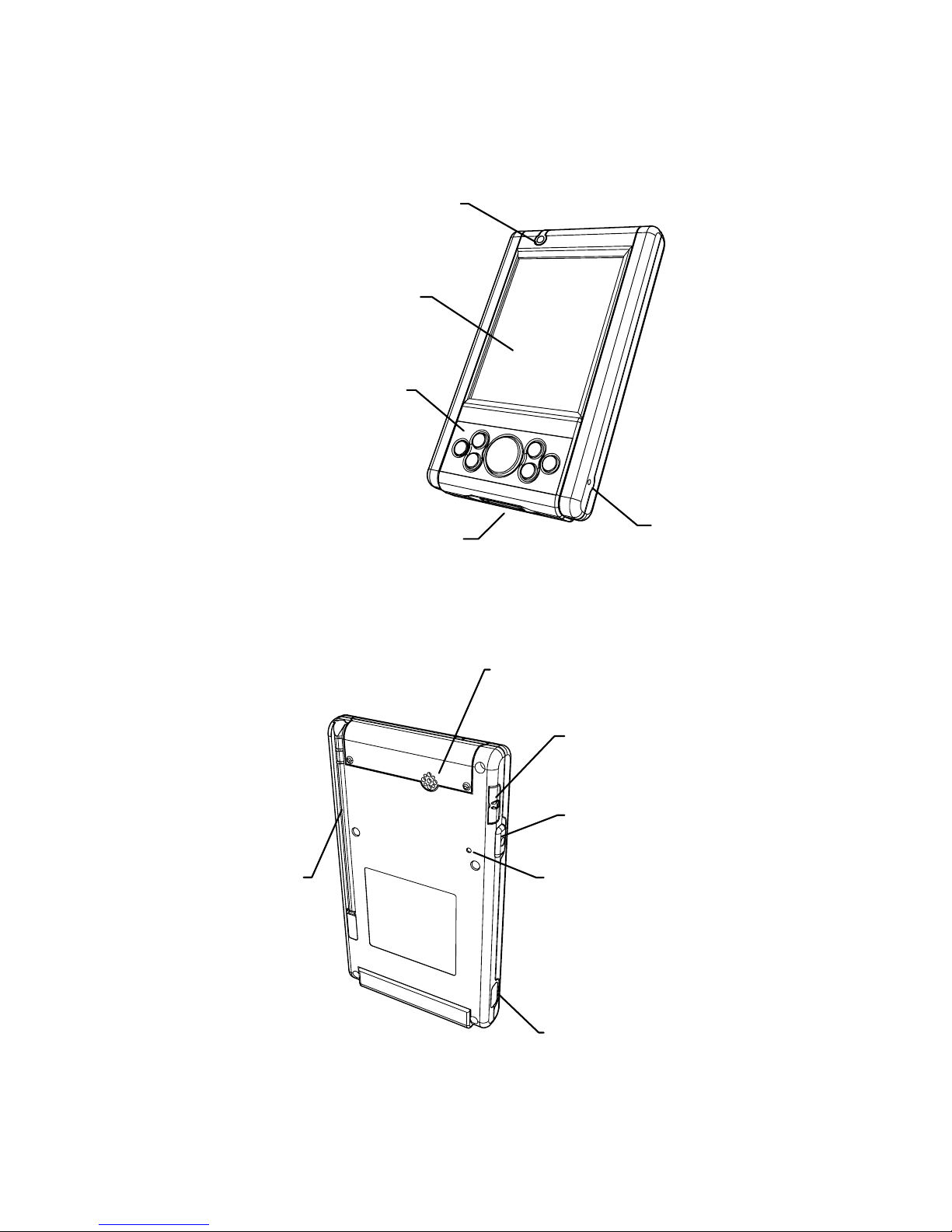
Parts of the R1000 Series
LCD Displa
y
Communication Port
Keypad
Mic
LED
IrDA Port
Reset Switch
Side Button
A
udio
Connecto
r
Speaker
Stylus
3
Page 6

4
Getting Started
Before you can use your R1000, perform these
basic setup procedures:
• Charge the battery
• Start the R1000
Charging the Battery
Before using your R1000 for the first time, charge
the built-in Lithium-Polymer battery for about 3
hours using the Cable Sync and Charger with AC
Adapter attached. Follow these same procedures
to recharge the battery.
When the battery is fully used up, charge within
72 hours to prevent any data loss.
• Connect the AC Adapter to the Cable Sync
and Charger.
• Insert the Cable Sync and Charger to the
Communication Port found at the bottom of
the R1000.
• Plug the AC Adapter into a wall outlet and
turn on a wall outlet, if applicable.
• The Terminal Status LED turns GREEN to
indicate charging.
• The LED will turn RED after the battery is
fully charged. This will take approximately 3
hours.
Starting the R1000
Press the Power Button to turn the R1000 on or
standby. In the case where the Power button
is pressed for the first time after hard reset,
the terminal initializes its unique Flash File
system, the booting splash screen will be
displayed for about 10 seconds.
Page 7

5
Page 8

Aligning the Screen
Remove the Stylus from its storage silo on the
back of the R1000. To align your R1000, the
cursor on the touch screen needs to be aligned
with the tip of your Stylus.
Windows CE Model:
• Tap and hold the center of each target that
appears on the screen with the tip of the
Stylus.
• Tap anywhere on the screen to finish to the
setting.
Press & hold stylus on the center
of the target. Repeat as the target
moves around the screen.
+
Target
Windows CE alignment screen
6
Page 9
Linux Model:
• When the Welcome screen appears, tap
anywhere on the screen to continue to the
align screen.
• Tap the center of each target that appears on
the screen with the tip of the Stylus.
• Follow the on-screen instructions, which
allow you to set the language, your city and
time zone.
+
Welcome to Qtopia
Touch the crosshairs firmly and
accurately to calibrate your screen.
Target
Linux alignment screen
Note: The process will repeat if it detects an
inaccuracy. These screens also appear every
time you perform a hard reset.
7
Page 10
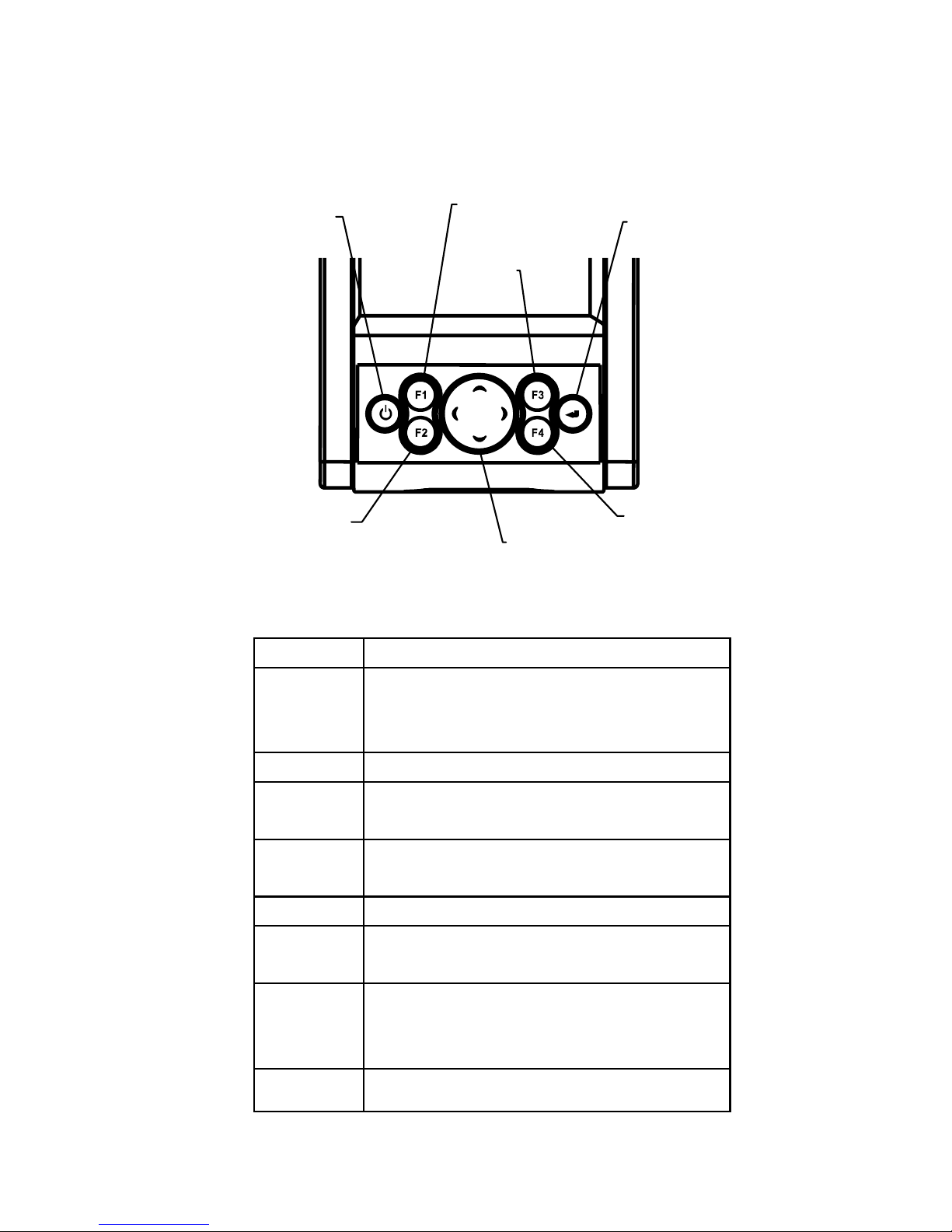
Using the Keypad and Side Button
Enter
F2
F3
F1
Powe
r
Cursor
F4
Windows CE Model:
Key Action
Power Press Power to either set
the PDA to standby or ON
mode.
F1 Press F1 to start Word Pad.
F2 Press F2 to start Internet
Explorer.
F3 Press F3 to start Media
Player.
F4 Press F4 to display Inbox.
Enter Press Enter after entering data
or a command.
Cursor Press cursor keys to move the
cursor left, right, up and down
on the screen.
Side Press Side Button to launch
8
Page 11

9
Button Bluetooth application.
Linux Model:
Key Action
Power Press Power to either set
the PDA to standby or ON
mode.
F1 Press F1 to start Media
Player.
F2 Press F2 to display the
Launcher Screen.
F3 Press F3 to display Calendar.
F4 Press F4 to display Contacts.
Enter Press Enter after entering data
or a command.
Cursor Press cursor keys to move the
cursor left, right, up and down
on the screen.
Side
Button
Press Side Button to start
Voice Recorder.
Page 12

10
Using the Stylus
The Stylus selects items and enters information.
The Stylus functions as a mouse.
Windows CE Model:
• Tap: Touch the screen once with the Stylus
to select an item or option.
• Double-Tap: Touch the screen twice with the
Stylus to open an item.
• Drag: Hold the Stylus on the screen and drag
across the screen to select text and
messages. Drag in a list to select multiple
items.
• Tap-and-Hold: Tap and hold the Stylus on an
item to see the available actions.
Linux Model:
• Tap: Touch the screen once with the Stylus
to open an item and select an option.
• Tap-and-Hold: Tap and hold the Stylus on an
item to see the Properties.
Page 13

Initiating the Screen
Windows CE Model:
When you turn on your terminal, the Desktop
screen appears. You can also display it by
tapping the Desktop icon at the lower right of the
screen. On the Desktop screen, you can see the
programs. You can start the programs by tapping
on the Start Menu.
Double-Tap the item
to start the application
Tap this icon to
show the Start
Menu
Input method icon
Tap here to
show the
Desktop icon
11
Page 14

Linux Model:
When you turn on your terminal, the Launcher
screen appears. You can also display it by
pressing F1 key. On the Launcher screen, you
can see the following programs.
Input method icon
Tap the item to star
t
the application
Tap the Navigation Tab
to select a categor
y
12
Page 15

Input Methods
Windows CE Model:
Tap the Input method icon to pop up and hide the
Software Keyboard.
Keyboard
Linux Model:
By default, the Handwriting input method icon
appears at the bottom left of screen. Tap the
triangle to the right of the input method icon to
pop up a list of input methods, e.g. Handwriting,
Pickboard, Keyboard and Unicode. Tap the input
method you prefer. The icon will change to reflect
your choice. Tapping the input method icon
alternately pops-up the input area and hides the
input area.
Handwriting
13
Page 16

Pickboard
Keyboard
Unicode
14
Page 17

15
Turn on and off the Backlights
Press and hold the Power Key to turn on and off
the backlight for both the LCD Display and the
Keypad.
To turn off the backlights, press and hold the
Power Key. This will activates the Keypad
backlight to turn off first followed by the Display
backlight.
To turn on the backlights again when both LCD
Display and Keypad backlights are in the offmode, press and hold the Power Key.
Using the Headset
To use the Headset, plug the Headset Jack into
the audio connector on the side of the terminal.
Page 18

16
Resetting Your R1000 Terminal
If your R1000 terminal stops responding to input,
reset it.
Performing a Soft Reset
Push the Reset Switch with a Stylus gently to
perform a soft reset. A soft reset restarts your
R1000 terminal and saves all stored records and
entries.
Caution: Files that remain open during a soft
reset may not be stored / saved. DO NOT
perform a soft reset if the terminal is suspended.
Press the Power Button to wake the terminal; if
the terminal does not turn on, perform soft reset.
Note: In case password setting is applied to
Windows CE model, press F2 and Enter button
simultaneously to show the Software Keyboard.
Performing a Hard Reset
A hard reset restarts your R1000 terminal, but
erases all stored records and entries.
Note: You can restore any data previously
synchronized with your computer during the next
ActiveSync operation.
To perform a hard reset on the terminal:
• While holding the Power Button, gently push
the Reset Switch with a Stylus.
• Hold for about 5 seconds.
• As the terminal reboots, the booting splash
screen displays for about 10 second s.
Page 19

17
• Realign the screen.
Note: With a hard reset, Formats, Preferences,
and other settings are restored to their factory
default settings.
Page 20

18
Host Communications
The R1000 series terminal can communicate
with a host PC through its communication port
using the Cable Sync and Charger.
Refer to www.olympus-ost.com for software
download.
Using the Cable Sync and Charger
To communicate through the Cable Sync and
Charger:
• Ensure all connections between the Cable
Sync and Charger and the host computer are
secure.
• Power on the host computer and the terminal.
• Plug the Cable Sync and Charger to the
Serial Port on the terminal.
• Begin host communications as specified by
your application.
Page 21

Using Online Help
The online help is installed as a default. You can
get more information about both operating
systems from there.
Windows CE Model:
To use online help, show Start Menu icon and
tap Help icon.
Tap Start Menu icon
Help icon
19
Page 22

Linux Model:
To use online help, select Applications tab at the
top of the screen and tap Help Browser icon.
Help Browser icon
Choose Applications tab
20
Page 23

21
Maintaining the R1000
To maintain your R1000 in good working
condition:
• Do not scratch the screen. Use the supplied
Stylus or plastic-tipped pens intended for use
with a touch-sensitive screen. Never use a
pen or pencil or other sharp object on the
screen.
• Although your R1000 is water and dust
resistant, do not expose it to rain or moisture
for an extended period of time. Treat your
R1000 as you would for a pocket calculator
or other electronic instrument.
• The touch-sensitive screen of your R1000
contains glass. Do not drop your R1000 or
subject it to a strong impact.
• Protect your R1000 from temperature
extremes. Do not leave it on the dashboard
of a car on a hot day, and keep away from
heat sources.
• Do not store or use your R1000 in any
location that is extremely dusty, damp or wet.
• If the surface of the R1000 screen becomes
soiled, clean it with a soft cloth moistened
with a diluted window-cleansing solution.
Page 24

22
Troubleshooting
Problem Cause Solution
LithiumPolymer battery
not charged.
Charge the
Lithium-Polymer
Battery in the
R1000.
R1000 does not
turn on.
System crash. Perform a hard
reset.
Loose
connections.
Check the
connection on your
R1000 and wall
outlet.
Rechargeable
LithiumPolymer battery
did not charge.
Battery failed. Perform a hard
reset.
Cannot see
characters on
display.
R1000 not
powered on.
Press the Power
Button.
Distance from
the other
device is more
than 1 meter.
Bring the terminal
closer to the device
and attempt
communication
again.
Obstruction
interfered with
communication.
Check the path to
ensure no objects
obstruct the way.
Fail to
communicate
using IrDA.
Devices too
close together.
Place at least 1
inch apart.
Page 25

23
Inappropriate
room lighting.
Adjust room
lighting or move to
a different location.
Problem Cause Solution
Cable Sync and
Charger
unplugged from
terminal or from
host computer
during
communication.
Ensure
connections and
re-transmit.
Incorrect cable
configuration.
See your System
Administrator.
During data
communication,
no data was
transmitted, or
transmitted
data was
incomplete.
Communication
software was
incorrectly
installed or
configured.
Download setup
program from
www.olympusost.com and
perform setup
again.
No sound is
audible.
Volume setting
is low or turned
off.
Check the System
Volume slider in
the Sounds &
Reminders
properties dialog
box to make sure
the volume is not
turned down.
Page 26

24
R1000 turns off
itself.
R1000 is
inactive.
Your R1000 turns
off after a period of
inactive interaction.
This period can be
set from 1 to 5
minutes, in 1minute interval.
Check the Power
dialog box and
change the setting
if you need a
longer delay before
the automatic shut
off feature
activates.
Problem Cause Solution
R1000 does not
recognize my
handwriting.
Character
strokes written
incorrectly with
the stylus.
Refer to the Block
Recognizer.
Tapping the
screen buttons
or icons does
not activate the
corresponding
feature.
LCD screen
does not be
aligned
correctly.
Align the screen.
Choose Align
Screen from
System tab.
Too many files
stored on the
terminal.
Delete unused
memos and
records. You can
save these records
on your computer.
A message
appears stating
that your
R1000 terminal
memory is full
Memory
allocation too
low.
Adjust memory
allocation.
Page 27

25
Too may
applications
installed on
terminal.
If you have
installed additional
applications on
your R1000,
remove them to
recover memory.
When receiving
beamed data,
an out of
memory
message
appears.
Not enough
free memory
available for
receiving data.
Your R1000
terminal requires at
least twice the
memory available
as the data you are
receiving.
Page 28

Regulatory and Warning Information
Radio Frequency Interface Requirements
Tested to comply with FCC Standards.
FOR HOME OR OFFICE USE
Note: This equipm ent has been tes ted and found to compl y with the
limits for Clas s B d ig ital device, pur s uant to P ar t 1 5 of the FCC r ul es .
These limits are designed to provide reasonable protection against
harmful interference in a residential installation. This equipment
generates, uses, an d can radiate radio f requency energy and, if not
installed and used in accordance with the instruction manual, may
cause harmf ul interference to radio com munications. However there
is no guarantee that interference will not occur in a particular
installation. If the equipment does cause harmful interference to
radio or televis ion rec eption, which can be deter mined b y turning th e
equipment off and on, the user is encouraged to try to correct the
interference by one or more of the following measures:
• Connect the equipment into an outl et on a circuit dif ferent from
that to which the receiver is connected.
• Consult the dealer or experienced radio/TV technician for help.
This device com plies with Part 15 of the FCC Rules. Operation is
subject to the foll owing 2 conditions: (1) this de vice may not cause
harmful interference, and (2) this device must accept any
interference received, including interference that may cause
undesired operation.
NOTE: THE MANUFACTURER IS NOT RESPONSIBLE FOR ANY
RADIO OR TV INTERFERENCE CAUSED BY UNAUTHORIZED
MODIFICATIONS TO THIS EQUIPMENT.
SUCH MODIFICATIONS COULD VOID THE USER’S AUTHORITY
TO OPERATE THE EQUIPMENT.
Radio Frequency Interference
Requirements - Canada
This device complies with RSS210 of Industry & Science Canada.
Operation is subject to the following two conditions: (1) this device
may not cause harm ful interference and (2) th is device must accept
any interference received, including interference that may cause
undesired operation.
This Class B digital apparatus complies with Canadian ICES-003.
Cet appareil numérique de la classe B est conforme à la norme
NMB-003 du Canada.
The term “IC” befor e the radio cer tific ation on ly s ignif ies that Indus tr y
Canada technical specifications were met.
26
Page 29

27
Bluetooth Regulatory Information
FHSS Descriptions
1. Output Power and Channel Separation of a Bluetooth Device
in the Different Operating Modes
The different operating modes (data-mode, acquisition-mode) of a
Bluetooth device don't influence the output power and the channel
spacing. There is only one transmitter, which is driven by identical
input parameters concerning these t wo parameters. Only a d ifferent
hopping sequence will be used. For this reason, t he RF parameters
in one op-mode are sufficient.
2. Frequency Range of a Bluetooth Device
The maximum frequenc y of the de vice is 2402 MHz - 2 480 MHz. T his
is according the Bluetooth Core Specification V 1.1.
3. Co-Ordination of the Hopping Sequence in Data Mode to
Avoid Simultaneous Occupancy by Multiple Transmitters
Bluetooth units, which want to communicate with other units, must be
organized in a structure called piconet. This piconet consist of
maximum 8 Bluetoot h units. One unit is the m aster the other seven
are the slaves. The m aster co- ordinates f requenc y occupation in this
piconet for all units . As the master hop sequence is der ived from it's
BD address which is unique for every Bluetooth device, additional
masters intend ing to esta blish new piconets will alwa ys use diff erent
hop sequences.
4. Example of a Hopping Sequence in Data Mode: Example of a
79 hopping sequence in data mode:
40, 21, 44, 23, 42, 53, 46, 55, 48, 33, 52, 35, 50, 65, 54, 67, 56, 37,
60, 39, 58, 69, 62, 71, 64, 25, 68, 27, 66, 57, 70, 59, 72, 29, 76, 31,
74, 61, 78, 63, 01, 41, 05, 43, 03, 73, 07, 75, 09, 45, 13, 47, 11, 77,
15, 00, 64, 49, 66, 53, 68, 02, 70, 06, 01, 51, 03, 55, 05, 04
5. Equally Average Use of Frequencies in Data M ode and Short
Transmissions
The generation of the hopping sequence in connection mode
depends essentially on two input values:
1. LAP/UAP of the master of the connection
2. Internal master clock
The LAP (lower address part) is the 24 LSB's of the 48 BDADDRESS. The BD A DDRESS is an u nambiguous num ber of ever y
Bluetooth unit. The UAP (upper address part) are the 24 MSB's of
the 48 BD-ADDRESS. The internal clock of a Bluetooth unit is
derived from a free running clock, which is never adjusted and is
never turned off. For synchronization with other units, only the offsets
are used. It has no relation to the time of the day. Its resolut ion is at
least half the RX/T X slot le ngth of 312. 5IJs. T he clock has a c ycle of
about one day (23h30). In most case it is implem ented as a 28-bit
Page 30

28
counter. For the derivin g of the hop ping s equence the entire L AP (24
bits), 4 LSB's (4 bits) (Inpu t 1) and the 27 MSB's of the clock (Input
2) are used. With this input va lues dif ferent mathem atic al pr oc ed ures
(permutations, additions, XOR-operations) are performed to
generate the sequence. T his will be done at the beginning of every
new transmission.
Regarding short transmissions, the Bluetooth system has the
following behavior:
The first connection between the two devices is established, a
hopping sequence is generated. For transmitting the wanted data,
the complete hopp ing s equ enc e is not used and the connection ends .
The second connect ion will be es ta bl ished. A new hopping sequ enc e
is generated. Due to the fact that the Bluetooth c lock has a dif ferent
value, because the period between the two transmission is longer
(and it cannot be shorter) than the minimum resolution of the clock
(312.5 s). The hopping sequence will always differ from the first
one.
6. Receiver Input Bandwidth, Synchronization and Repeated
Single or Multiple Packets
The input bandwidth of the receiver is 1 MHz. In e very connectio n,
one Bluetooth device is the m aster and the other one is the slave.
The master determ ines the hopping sequence (see section 5). The
slave follows this sequence. Both dev ices shift between RX and TX
time slot accor din g t o t he c l ock of the mas ter . Add it ionally the type of
connection (e.g. single or m ulti-slot pac ket) is set up at the begi nnin g
of the connection. T he master adapts its hoppin g frequency and its
TX/RX timing is ac cordin g to the pack et t ype of the co nnecti on. Also ,
the slave of the connection uses these settings. Repeating of a
packet has no influence on the hopping sequence. The hopping
sequence generated by the m aster of the connec tion wil l be fol lowed
in any case. That m eans, a repeated pack et will not be send on t he
same frequency, it is send on the next frequency of the hopping
sequence.
7. Dwell Time in Data Mode
The dwell time of 0.3797s within a 30 seconds period in data mode is
independent from the packet t ype ( packet length). T he c alcu lat ion f or
a 30 seconds period is as follows:
Dwell time = time slot length * hop rate / number of hopping channels
*30s
Example for a DH1 pack et (with a maxim um length of one tim e slot)
Dwell time = 625 IJs * 1600 1/s /79 * 30s = 0.3797s (in a 30s period)
For multi-slot pack et the hopping is reduced according to the length
of the packet.
Example for a DH5 packet (with a maximum length of five time slots)
Dwell time = 5 * 625 s * 1600 * 1/5 *1/s / 79 * 30s = 0.3797s (in a
30s period)
Page 31

29
This is according the Bluetooth Core Specification V 1.1 for all
Bluetooth devices . Therefore, all Bluetooth devices comply with the
FCC dwell time requirement in the data mode. This was checked
during the Bluetooth Qualification tests. The Dwell time in hybrid
mode is approximately 2.6ms (in a 12.8s period).
8. Channel Separation in Hybrid Mode
The nominal channel spacing of the Bluetooth system is 1 MHz
independent of the operating mode. The maximum "initial carrier
frequency tolerance" which is allowed for Bluetooth is center = 75
kHz.
This was checked during the Bluetooth Qualification tests (Test
Case: TRM/CA/07-E) for three frequencies (2402MHz, 2441MHz,
2480 MHz).
9. Derivation and Examples for a Hopping Sequence in Hybrid
Mode
For the generation of the inquir y and page ho p sequences the same
procedures as desc ribed f or the d ata m ode are used ( see sec tion 5),
but this time with different input vectors:
• For the inquiry hop sequence, a predefined fixed address is
always used. T his r esu lt in the sa me 32 freque ncies used b y all
devices doing an inquiry but every time with a different start
frequency and phase in this sequenc e.
• For the page hop sequence, the device address of the paged
unit is used as the input vector. This results in the use of a
subset of 32 frequenc ies, which is s pec if ic f or that ini tia l s tate of
the connection esta blishm ent between the two units. A page to
different devices would result in a different subset of 32
frequencies.
So it is ensured that also in hybrid mode, the frequency is used
equally on average.
Example of a hopping sequence in inquiry mode:
48, 50, 09, 13, 52, 54, 41, 45, 56, 58, 11, 15, 60, 62, 43, 47,00, 02,
64, 68, 04, 06, 17, 21,08, 10, 66,70, 12, 14,19, 23
Example of a hopping sequence in paging mode:
08, 57, 68, 70, 51, 02, 42, 40, 04, 61, 44, 46, 63, 14, 50, 48, 16, 65,
52, 54, 67, 18, 58, 56, 20, 53, 60, 62, 55, 06, 66, 64
10. Receiver Input Bandwidth and Synchronization in Hybrid
Mode
The receiver input bandwidth is the same as in the data mode (1
MHz). When two B luetooth devices esta bl is h co ntac t f o r the f irs t t ime,
one device sends an inquiry access code and the other device is
scanning for this inquiry access code. If two devices have been
connected previous ly and want to start a ne w transmiss ion, a similar
procedure takes place. The only difference is, ins tead of the inquiry
Page 32

30
access code, a speci al ac c es s c ode, der iv ed f rom the BD-ADDRESS
of the paged device will be, will be sent by the master of this
connection. Due to the fact that both units have been connected
before (in the inquiry procedure) the paging unit has timing and
frequency information about the page scan of the paged unit. For this
reason the time to establish the connection is reduced.
11. Spread Rate I Data Rate of the Direct Sequence Signal
The spread rate / data rate in inquiry and paging mode can be
defined via the acc es s c ode. The access code is the onl y criter io n f o r
the system to check if there is a valid transmission or not. If you
regard the presenc e of a v alid acc ess c ode as one bit of infor m ation,
and compare it with the length of the access code of 68 bits, the
spread rate / data rate will be 68/1.
12. Spurious Emission in Hybrid Mode
The dwell in hybrid mode is shorter than in data mode. For this
reason the spurious em issions average level in data m ode is worst
case. The spurious emissions peak level is the same for both modes.
Battery Caution
Caution: Danger of explosion if battery is
incorrectly replaced. Replace only with the same
type recommended by the manufacturer. Discard
used batteries according to the manufacturer’s
instruction.
Service Information
Refer to www.olympus-ost.com to get more
information
Page 33

Page 34

SNE100959, Revision C
Olympus Technologies Singapore Pte Ltd
41 Science Park Road #04-10 The Gemini
Singapore Science Park 2, Singapore 117610
Tel: (65) 6777 2508
Web Site: www.olympus-ost.com
 Loading...